hydrogeologic and geotechnical investigation workplan · hydrogeologic and geotechnical...
TRANSCRIPT
HYDROGEOLOGIC AND GEOTECHNICAL INVESTIGATION WORKPLAN
PROPOSED LATERAL EXPANSION ECO-VISTA LANDFILL
ECO-VISTACLASS 1 LANDFILL
ADEQ PERMIT NO. 0290-S1-R2 AFIN: 72-00144
PREPARED FOR:
Waste Management Eco-Vista, LLC 2210 Waste Management Drive
Springdale, Arkansas 72762
PREPARED BY:
Terracon Consultants, Inc. 25809 Interstate 30 South Bryant, Arkansas 72022
July 2010 Rec’d Digitally
AFIN:_________________________
PMT#:_________________________ SW
DOC ID#:______________________ MD
TO:___________________________
By Barbara Mathews at 8:14 am, Jul 20, 2010
72-001440290-S1-R2
57959
BS> file


WM Eco-Vista LandfillProject No. 35097120 July 14, 2010
ii
TABLE OF CONTENTS
1.0 INTRODUCTION ........................................................................................ 1 2.1 BACKGROUND........................................................................................ 1 2.2 HYDROGEOLOGIC SETTING ................................................................. 2
2.0 SITE CHARACTERIZATION ..................................................................... 5 2.1 LITERATURE REVIEW ............................................................................ 5 2.2 AERIAL PHOTOGRAPH ANALYSIS........................................................ 5 2.3 SURFACE GEOLOGIC MAPPING ........................................................... 5 2.4 SURFACE GEOPHYSICAL SURVEY ...................................................... 6 2.5 SUBSURFACE EXPLORATION PROGRAM ........................................... 8
2.5.1 Trackhoe Test Pits ...................................................................... 9 2.5.2 Borehole Drilling Program .......................................................... 10
3.0 GROUNDWATER FLOW CHARACTERIZATION ................................... 13 3.1 POTENTIOMETRIC SURFACE .............................................................. 13 3.2 AQUIFER TESTING ................................................................................ 14 3.3 DYE TRACER TESTING......................................................................... 14
4.0 GROUNDWATER QUALITY CHARACTERIZATION .............................. 154.1 GROUNDWATER QUALITY MONITORING ........................................... 15 4.2 MONITORING WELL CONSTRUCTION ................................................. 15 4.3 DECONTAMINATION PROCEDURES ................................................... 16
5.0 REPORT PREPARATION ........................................................................ 17
6.0 REFERENCES .......................................................................................... 18
FIGURES
FIGURE 1. SITE LOCATION MAP
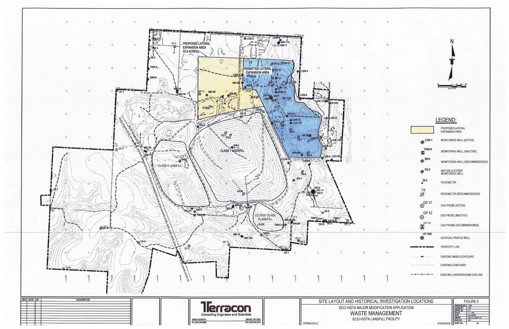
FIGURE 2. SITE LAYOUT AND HISTORICAL INVESTIGATION LOCATIONS
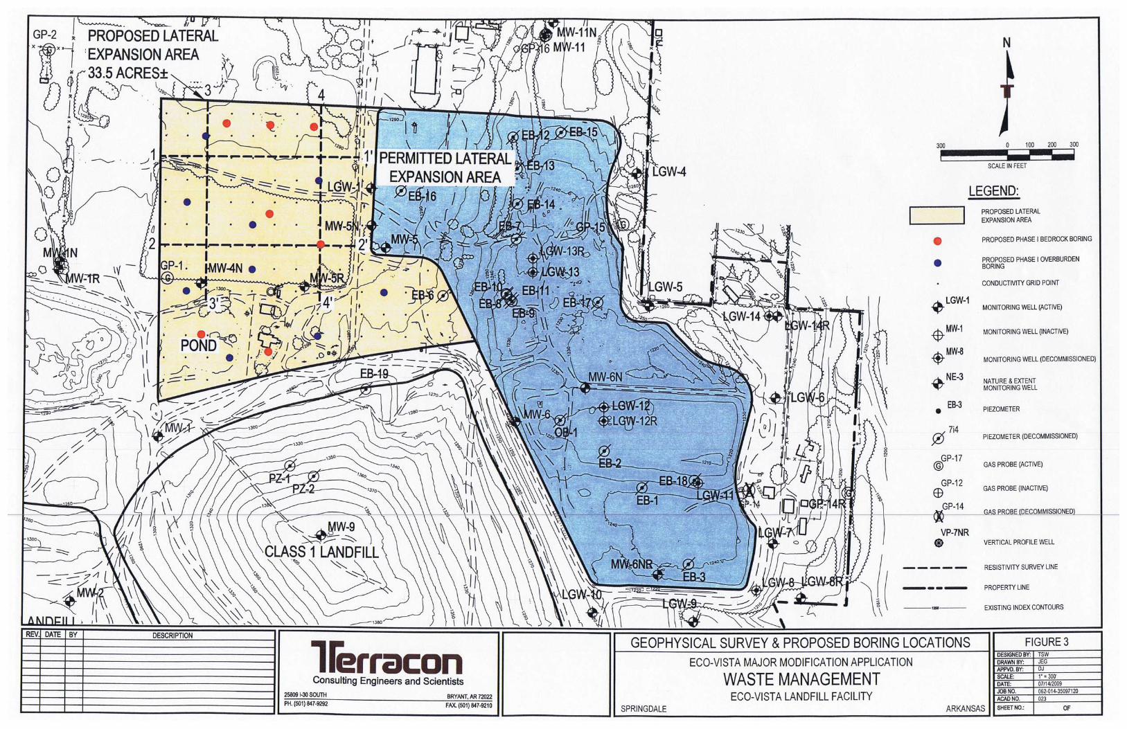
FIGURE 3. GEOPHYSICAL SURVEY AND PROPOSED BORING LOCATIONS

WM Eco-Vista LandfillProject No. 35097120 July 14, 2010
iii
APPENDICES
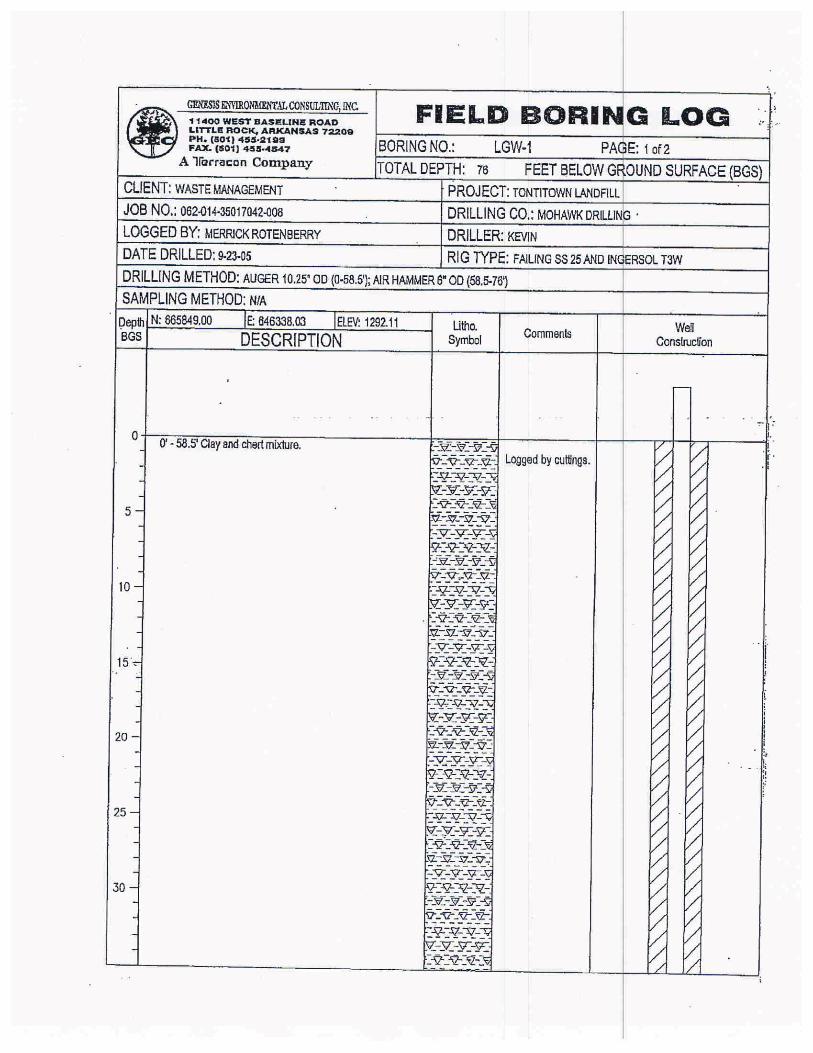
APPENDIX A. BORING LOGS FOR MONITORING WELLS PREVIOUSLY INSTALLED IN PROPOSED LATERAL EXPANSION AREA

WM Eco-Vista LandfillProject No. 35097120 July 14, 2010
1
1.0 INTRODUCTION
Waste Management Eco-Vista Landfill, LLC, owns and operates the Eco-Vista Class 1 Municipal Solid Waste landfill (“Eco-Vista Landfill”) under Arkansas Department of Environmental Quality (ADEQ) Solid Waste Permit 0290-S1-R2. The Eco-Vista Landfill is located approximately 2.5 miles south of Tontitown in a portion of Sections 14 and 23, Township 17 North, Range 31 West, Washington County, Arkansas. A site location map is presented as FIGURE 1. The property has historically been used and operated as a solid waste disposal site with both Class 1 and Class 4 disposal areas.
1.1 BACKGROUND
Waste Management Eco-Vista Landfill, LLC is submitting this workplan for a hydrogeologic characterization associated with a proposed lateral expansion that consists of a 33.5 acre tract owned by Waste Management. A site layout map showing historical investigation locations with a delineation of the proposed expansion tract is included as FIGURE 2.Waste Management (WM) may also investigate other portions of their property to obtain additional information that could be helpful during the permitting process of the proposed lateral expansion area.
This characterization is intended to satisfy the requirements of Arkansas Pollution Control & Ecology Commission (APC&EC) Regulation 22, Chapter 11, “Geotechnical and Hydrogeological Investigations,” including Section 22.1102 (e) pertaining to landfills in the Boone and St. Joe Formations.
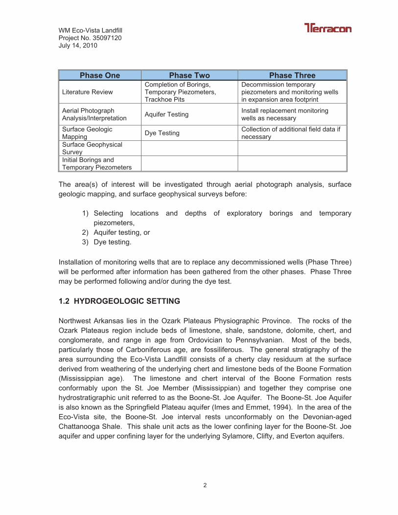
The tasks in this workplan are intended to be performed in phases so that information gained during earlier phases can be incorporated into later phases. The three phases are as outlined in the following table:
WM Eco-Vista LandfillProject No. 35097120 July 14, 2010
2
Phase One Phase Two Phase Three
Literature Review Completion of Borings, Temporary Piezometers, Trackhoe Pits
Decommission temporary piezometers and monitoring wells in expansion area footprint
Aerial Photograph Analysis/Interpretation Aquifer Testing Install replacement monitoring
wells as necessary
Surface Geologic Mapping Dye Testing Collection of additional field data if
necessarySurface Geophysical SurveyInitial Borings and Temporary Piezometers
The area(s) of interest will be investigated through aerial photograph analysis, surface geologic mapping, and surface geophysical surveys before:
1) Selecting locations and depths of exploratory borings and temporary piezometers,
2) Aquifer testing, or 3) Dye testing.
Installation of monitoring wells that are to replace any decommissioned wells (Phase Three) will be performed after information has been gathered from the other phases. Phase Three may be performed following and/or during the dye test.
1.2 HYDROGEOLOGIC SETTING
Northwest Arkansas lies in the Ozark Plateaus Physiographic Province. The rocks of the Ozark Plateaus region include beds of limestone, shale, sandstone, dolomite, chert, and conglomerate, and range in age from Ordovician to Pennsylvanian. Most of the beds, particularly those of Carboniferous age, are fossiliferous. The general stratigraphy of the area surrounding the Eco-Vista Landfill consists of a cherty clay residuum at the surface derived from weathering of the underlying chert and limestone beds of the Boone Formation (Mississippian age). The limestone and chert interval of the Boone Formation rests conformably upon the St. Joe Member (Mississippian) and together they comprise one hydrostratigraphic unit referred to as the Boone-St. Joe Aquifer. The Boone-St. Joe Aquifer is also known as the Springfield Plateau aquifer (Imes and Emmet, 1994). In the area of the Eco-Vista site, the Boone-St. Joe interval rests unconformably on the Devonian-aged Chattanooga Shale. This shale unit acts as the lower confining layer for the Boone-St. Joe aquifer and upper confining layer for the underlying Sylamore, Clifty, and Everton aquifers.
WM Eco-Vista LandfillProject No. 35097120 July 14, 2010
3
Dissolution of the Boone Limestone Formation present near the surface in northwest Arkansas is responsible for the formation of a distinctive surface topography known as karst terrain. The most direct evidence of karst terrain are the landforms that are unique to karst regions. These landforms are the direct result of the dissolution of soluble carbonate bedrock and typically have vertical and horizontal underground drainage. Karst features include sinkholes; karst windows; springs; caves; and losing, gaining, sinking, and underground streams (EPA, 1988). The typical karst terrain of Northwest Arkansas is characterized by solution valleys. These valleys are uniform in width, are most generally linear, and have steep slopes. Valley heads are somewhat cirque-like and simulate the appearance of sinkholes cut less than 90 degrees and are numerous across the region.
Few surface expressions showing dissolution of carbonate rocks have been observed in the vicinity of the Eco-Vista Landfill. Some surface expressions of karst features have been identified in the region by Brahana and Davis (1999) including a sinkhole, a sinking stream, and springs. The sinkhole and sinking stream are located more than two miles to the east of the Eco-Vista Landfill in the recharge area of Little Wildcat Springs (Brahana and Davis, 1999). Several off-site springs have also been identified within a mile of the proposed lateral expansion area.
The Eco-Vista Landfill is located in the upper Boone Formation. More precise placement within the upper Boone Formation is difficult because of the lack of correlative horizons within the interval. The Boone contact with the overlying Hindsville (Upper Mississippian) is exposed at several places in north Fayetteville (most notably, the valley of Scull Creek adjacent to the University of Arkansas Agricultural Farm). This locality lies less than three (3) miles south of the Eco-Vista Landfill, and if regional dip is assumed, that would place the Eco-Vista Landfill site less than 90 feet below the top of the Boone Formation. At this horizon, it is expected that the upper Boone would be relatively free of karst features, particularly caves and sinkholes, and that the regolith would reach significant thicknesses.
The movement of groundwater in the Boone-St. Joe Aquifer occurs in a combination of two ways: concentrated flow through subsurface conduits flowing to springs and diffuse flow through the aquifer which also discharges at springs. Areas of the Boone-St. Joe Aquifer characterized by concentrated flow represent a developed karstified system. These systems are generally defined as having well developed sinkholes and losing streams, which drain surface water directly to the subsurface conduits. The groundwater flow velocities are generally high, typically in the feet per hour range. The conduits are well developed and connected to solution fractures that discharge to springs. The discharge from this type of spring generally responds rapidly to rainfall and is “flashy” (EPA, 1988).
Areas of the Boone-St. Joe Aquifer characterized by diffuse flow represent a less karstified or incipient karst system. The groundwater flow in this system is through small bedrock openings that have undergone only limited solutional enlargement. Groundwater flow
WM Eco-Vista LandfillProject No. 35097120 July 14, 2010
4
velocities are low and groundwater may require months to travel a few feet through the aquifer (EPA, 1988). The discharge from diffuse flow springs is generally uniform and slow to respond to storm events.
Local groundwater flow generally follows topography to the bottom of valleys containing perennial streams or springs. Springs located at the base of the regional flow system are located above the contact where insoluble rocks are encountered or at structural barriers such as faults, which impede the development of conduits. Spring locations in the region are believed to be controlled by the contact between the Boone-St. Joe Formation and the underlying Chattanooga Shale Formation. The hydraulic gradient in the region generally ranges from 4.7 feet per mile (0.09 percent) to 121 feet per mile (2.29 percent) with an average of 53 feet per mile (1.01 percent) (Ogden, 1979).
WM Eco-Vista LandfillProject No. 35097120 July 14, 2010
5
2.0 SITE CHARACTERIZATION
2.1 LITERATURE REVIEW
In association with the preparation of this workplan, published regional information and the results of previous hydrogeologic investigations conducted at the Waste Management Eco-Vista site have been reviewed. Tasks performed as part of this workplan are proposed to build upon existing data and previously stated conclusions. Previously published information will continue to be reviewed and utilized during implementation of this workplan.
2.2 AERIAL PHOTOGRAPH ANALYSIS
In accordance with Section 22.1102 (c)(1) of APC&EC Regulation 22, aerial photographs of the study area will be analyzed to determine:
1. Fracture traces and fracture orientation if any; 2. Lineaments; 3. Sedimentary features; and 4. Depositional features.
In limestone aquifer systems, lineaments identified on aerial photographs may represent zones of fracturing and secondary porosity. The aerial photographs utilized for this analysis will be dated both prior to and after landfilling activities at the site. Results of previously conducted lineament analyses in the area will be utilized during this analysis. Aerial photographs will be included in the final report.
If lineaments are identified across the study site, borings or surface geophysical analysis will be conducted to confirm the presence and characteristics of these lineaments as possible preferred groundwater flow pathways.
2.3 SURFACE GEOLOGIC MAPPING
In accordance with Section 22.1102 (c)(2) of Regulation 22 detailed surface geologic mapping will be conducted within a 1-mile radius of the property boundary to identify the following:
1. Surface stratigraphy; 2. Structural features (including fracture orientation/spacing and fault
orientation/displacement/hydraulic characteristics); 3. Springs and seeps; 4. Karst features (sinkholes, caves, losing/disappearing streams, dolens, etc.);
WM Eco-Vista LandfillProject No. 35097120 July 14, 2010
6
5. Other geologic features that may directly affect groundwater flow; and 6. Domestic, agricultural and municipal water wells.
Results of previously conducted surface mapping in the area will be utilized during this analysis. All features will be located and identified on an area map to be presented in the final report.
2.4 SURFACE GEOPHYSICAL SURVEY
Under section 22.1102(c)(3) of APC&EC Regulation 22, a surface geophysical study must be conducted across the proposed expansion area utilizing one of the methods identified in the regulations. Acceptable geophysical methods include electromagnetic, resistivity, seismic refraction, ground penetrating radar, and other methods approved by the ADEQ . The surface geophysical study will help determine relevant changes in overburden or soil type and thickness, stratigraphic changes, and sedimentary features. The two (2) surface geophysical methods selected for this project are resistivity and surface conductivity. Both the surface conductivity and resistivity surveys were performed at the proposed expansion site by Terracon during the month of December, 2008.
Conductivity Survey
The conductivity survey was designed to be conducted on 100 foot centers. Prior to beginning the conductivity survey, the proposed expansion area was divided into a grid on 100 foot X 100 foot centers (see FIGURE 3). This grid spacing yielded a total of 137 nodes or locations for conductivity readings which is considered sufficient to provide the resolution necessary for mapping as required in APC&EC Regulation 22. It is anticipated that all data points, including both geophysical and geotechnical data points, will be specifically located on the established grid. This will provide more exact feature location information that can be accurately applied to the landfill design.
Electromagnetic (EM) surface geophysical techniques provide information about the terrain conductivity of the subsurface (McNeill, 1980). High terrain conductivity values are the result of subsurface materials, such as clay or shale, or saturated sediments. When combined with additional subsurface information, such as data obtained from test borings or test pits, this method provides a possible means for defining vertical and horizontal extent of clay layers and the overburden bedrock interface. This method also provides a correlation between different soil and rock types and their associated conductivity values. The following field procedures were used to conduct the terrain conductivity survey.
WM Eco-Vista LandfillProject No. 35097120 July 14, 2010
7
Since previous borings advanced at the site indicate bedrock as deep as 70 feet below ground surface (bgs), the surface conductivity survey was conducted utilizing a Geonics EM-34 transmitting and receiving system which has a greater penetration depth than an EM-31 system. A conductivity measurement was taken in both the horizontal dipole position (HD) and vertical dipole position (VD) at each of the grid points. Depending on the depth of interest, data can be collected at intercoil spacings of 10, 20, or 40 meters in both the vertical and horizontal dipole configurations. The effective penetration depths of these intercoil spacings are shown in the following table:
10M 20M 40M
HD 25 ft 50 ft 100 ft VD 50 ft 100 ft 200 ft
The EM-34 instrument is most responsive to the near-surface conditions in the HD configuration and to conditions at one-half the coil separation in the VD configuration. The data obtained from the survey was then placed in a computer contouring program (SurferTM
for Windows from Golden Systems, Inc.) and terrain conductivity maps were generated for the selected coil spacings which will be presented in the final hydrogeologic investigation report. Based on existing boring logs for the site which indicate bedrock ranges from 30 to 70 feet below ground surface (bgs), the 10 meter and 20 meter coil spacings were utilized.
Resistivity Survey
The resistivity survey was performed by using a Sting memory earth resistivity meter and the Swift automatic multi-electrode system (Sting/Swift imaging system). The electrical resistivity surface geophysical techniques provide information about the resistivity of the subsurface terrain materials. Low terrain resistivity values are the result of subsurface materials such as clay, shale or saturated sediments. High terrain resistivity values are the result of subsurface materials such as sand, gravel or bedrock. When combined with additional hydrogeologic data, such as data obtained from exploratory borings, this method provides a possible means for defining vertical and horizontal extent of clay layers and delineation of the bedrock/overburden interface. This method also provides a correlation between different soil and rock types and their associated resistivity values.
A total of four (4) resistivity lines were run across the proposed expansion area and subsurface profiles were generated using an electrode spacing of six (6) meters. As shown on FIGURE 3, two (2) of the lines were oriented north-south while the remaining two (2) lines were oriented east-west. The dipole-dipole array configuration was used to record the resistivity profiles. It was concluded that utilizing the dipole-dipole array would result in a high resolution profile to a depth estimated at roughly ten (10) to fifteen (15) percent of the resistivity line profile lengths. The exact depth that the imaging system will

WM Eco-Vista LandfillProject No. 35097120 July 14, 2010
8
record is dependent upon the actual resistivity of the earth materials and, if the target depth at a site is not reached using the dipole-dipole method, the Schlumberger method may be run using the same electrode line. The Schlumberger array can provide a resolution profile that is slightly deeper than the dipole-dipole array, but some resolution will be lost at the end of the profile due to the “boat shaped” ends of the cross section. Based on the data acquired utilizing the dipole-dipole array, it was determined that the Schlumberger method would not be necessary.
The data collected from each resistivity profile was recorded in the field with a laptop computer. The data was then processed using the AGI EarthImager 2D software. The AGI EarthImager 2D software inverts the apparent resistivity data and interprets the data to produce a two-dimensional (2D) true resistivity model for the subsurface. The resultant 2D resistivity cross section profiles will be used as an aid to further interpret the geologic and hydrogeologic characteristics of the area.
Geophysical Survey Results
Results from the surface geophysical surveys will be used with previously existing geological data (e.g., test borings and geologic field mapping) to make the following interpretations:
� Overburden thickness, � Depth of overburden bedrock interface, � Presence of fractures and/or faulting on site, � Identification of shallow aquifer heterogeneities, � The vertical and horizontal extent of clay layers, and � Correlation between different soil and rock types and their associated
resistivity/conductivity values.
After these interpretations are made, a boring and test pit program will be performed to verify the interpretations as described below. The surface geophysical results will be presented in the final report.
2.5 SUBSURFACE EXPLORATION PROGRAM
The intrusive portion of the site characterization (Phase 1 and 2) will be performed by utilizing borings and trackhoe test pits. The locations of these borings and trackhoe pits will be based, in part, on the results of the aerial photograph analysis, surface geologic mapping, and surface geophysical survey. Exact locations of borings will be coordinated with ADEQ. The information to be gathered from these locations includes:
WM Eco-Vista LandfillProject No. 35097120 July 14, 2010
9
1. Thickness and aerial extent of each distinct soil texture unit or petrologic unit; 2. Depth to bedrock and bedrock topography; 3. Rock Quality Designation (RQD) when coring bedrock; 4. Fracture density and fracture orientation; 5. Bit drop and loses or gains in drilling fluid; and 6. Borehole geophysical logs.
Extensive geologic and hydrogeologic data have previously been collected from the Eco-Vista Landfill site (see FIGURE 2). This data will be utilized to supplement the existing conceptual hydrogeologic model of the landfill as required by Section 22.1102 (b)(1) of APC&EC Regulation 22. Lithologic logs and geotechnical results from previous borings and test pits will be included in the final report.
Geotechnical samples will be collected from the borings and trackhoe pits. In accordance with Regulation 22, Section 22.1102 (c)(6), each textural horizon and will be classified using the Classification of Soils For Engineering Purposes (ASTM D-2487-69) and characterized with physical tests, if appropriate. Based on past investigations at the site, it is anticipated that a maximum of three (3) sets of physical tests will be required. The physical tests include:
1. Atterberg limits (ASTM D-4318); 2. Standard penetration test (ASTM D 1586-84 & D-1452); 3. Sieve analysis and grain size distribution curves (ASTM D-1140 & D-422); 4. Dry density, hydraulic conductivity/molding water content (%) relationship; 5. Remolded hydraulic conductivity (ASTM D-5084); 6. Unconsolidated, unconfined shear strength of soils (ASTM 2850-70); 7. Standard Proctor density curves (ASTM D 698 & ASTM D-1557); 8. Moisture-density relations of soils and aggregates (ASTM 1557-78); 9. One dimensional consolidation properties of soils (ASTM D2435-81); 10. One dimensional swell or settlement (ASTM D4546); 11. Moisture content of soils (ASTM 2216-80); 12. In-situ hydraulic conductivity tests (anticipated to be a combination of slug tests,
pumping tests, and borehole permeability tests).
2.5.1 Trackhoe Test Pits
It is anticipated that one (1) trackhoe test pit per acre will be excavated. Therefore, a total of thirty-four (34) trackhoe test pits are required to be excavated in the area under consideration for proposed expansion. Each test pit will be excavated to the depth capability of the trackhoe or to bucket refusal and the overburden material
WM Eco-Vista LandfillProject No. 35097120 July 14, 2010
10
encountered logged by a Terracon geologist. After logging of a test pit is completed, it will be backfilled using the excavated soil and compacted.
2.5.2 Borehole Drilling Program
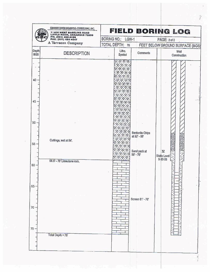
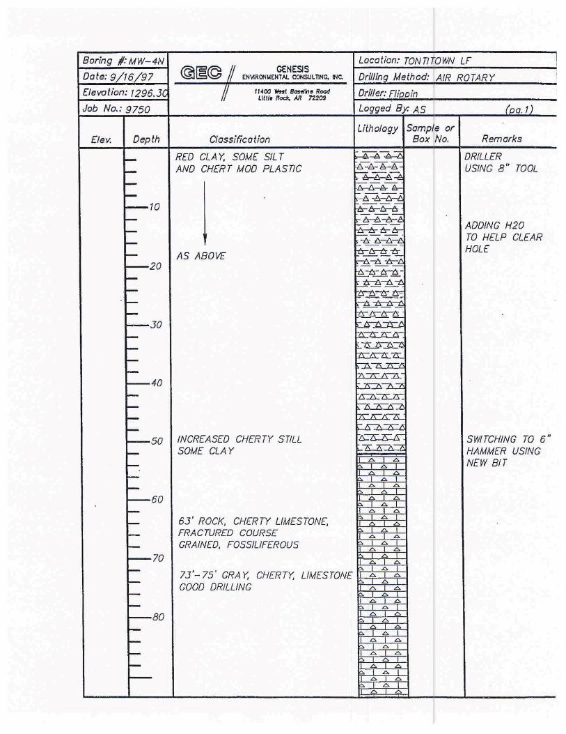
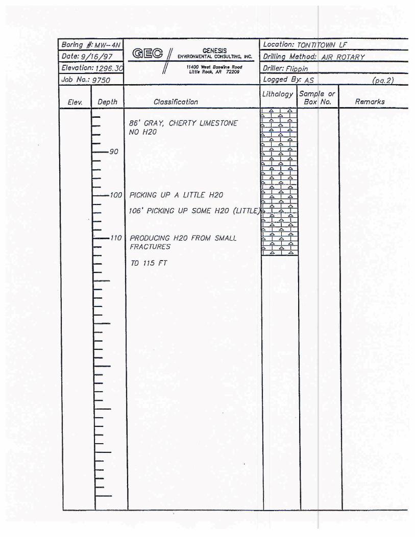
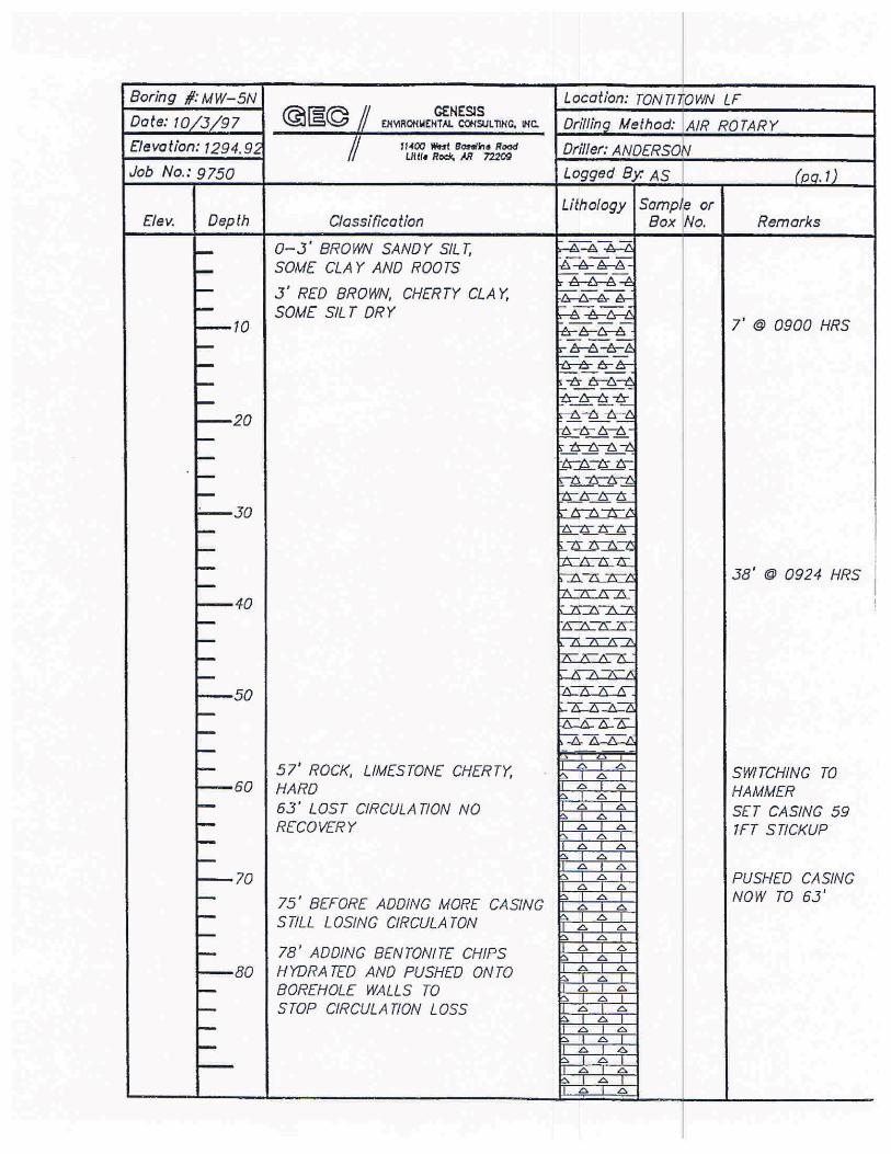
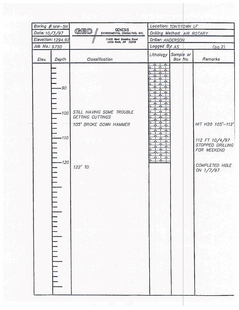
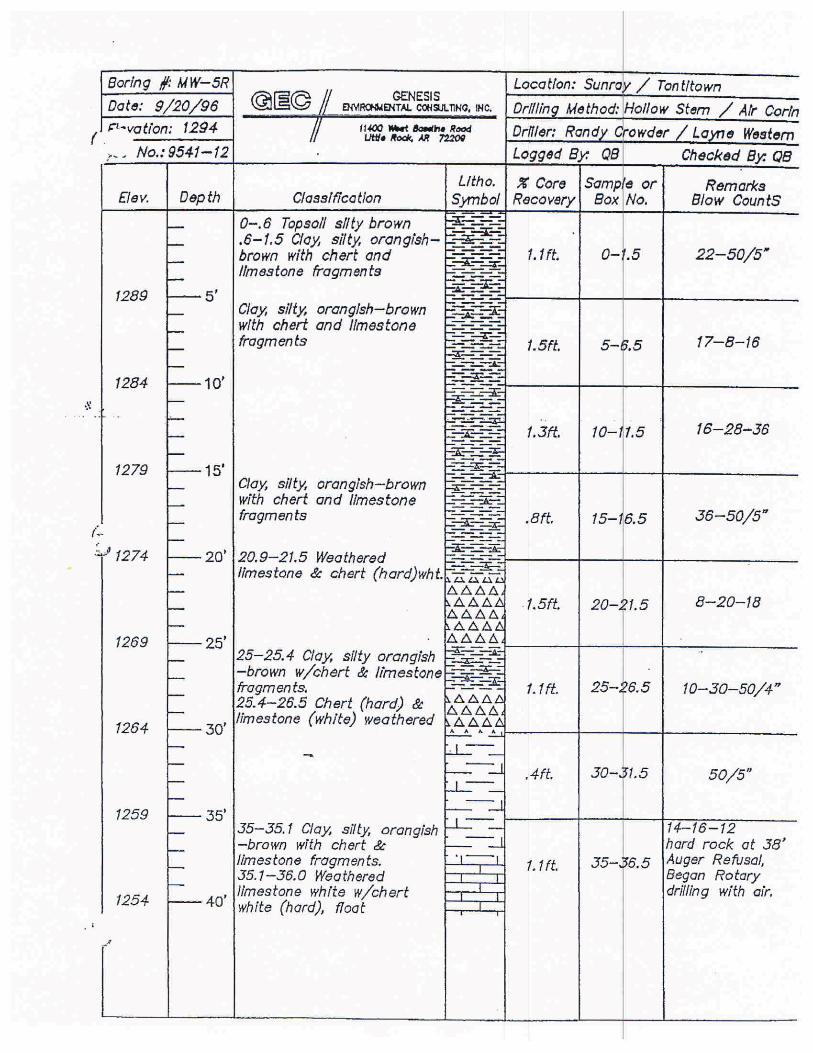
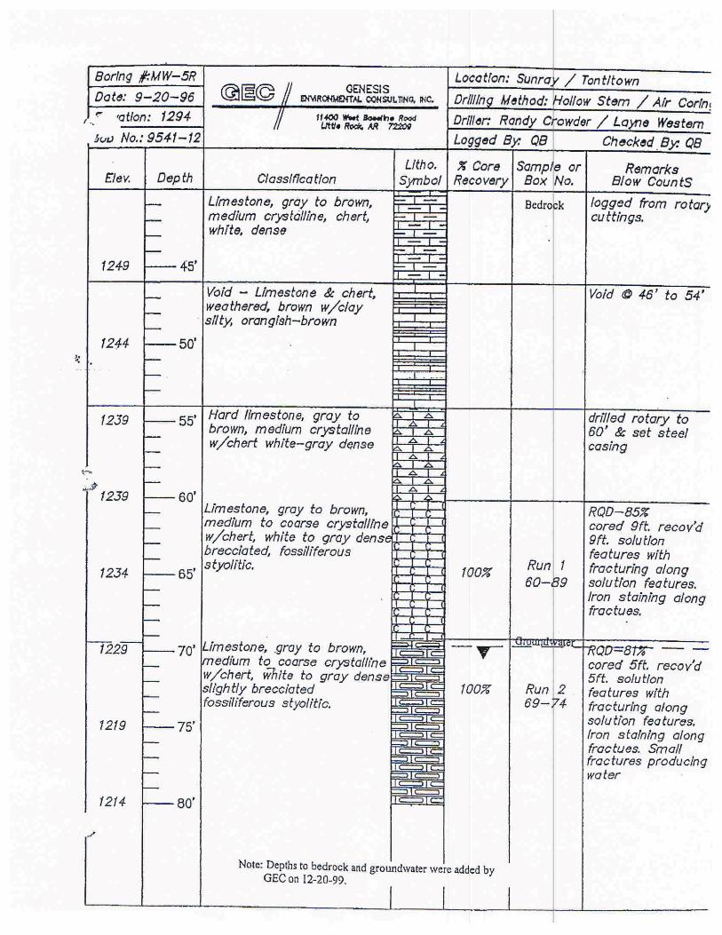
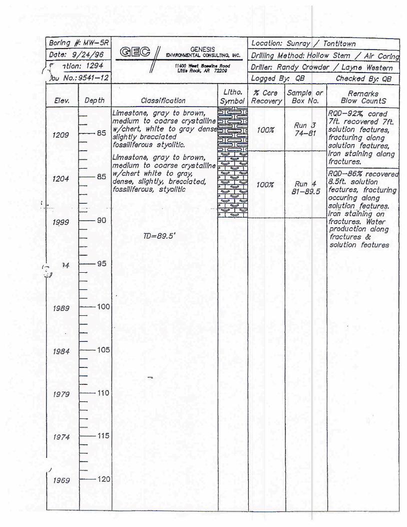
Section 22.1102 (e)(2) of APC&EC Regulation 22 requires a minimum spacing of one (1) boring per one (1) acre of expansion for landfills located within the outcrop area of the Boone-St. Joe Formations. The proposed lateral expansion area covers approximately 33.5 acres resulting in a requirement of at least thirty-four (34) exploratory borings to satisfy the Regulation 22 spacing requirement. It should be noted that five (5) borings have been advanced within the proposed expansion area during previous investigations: MW-4N, MW-5N, MW-5R, EB-6, and LGW-1 (see FIGURES 2 and 3). Therefore, information collected during drilling of these boreholes will be reviewed for consistency with current requirements and utilized in the evaluation of the proposed area. The actual number and location of additional borings required may be modified based on an interpretation of data generated from the surface geophysical surveys described in SECTION 2.4.
At a minimum, each of the exploratory borings drilled during this investigation will be advanced through the overburden (residuum) to the top of bedrock. Standard Penetration Test (SPT) coring at 5-foot intervals and/or continuous soil coring will be performed while drilling within the overburden. A review of the logs of previous borings advanced within and in close proximity to the proposed expansion area indicates that the depth to the bedrock-overburden interface is generally around 60 feet, consequently, there is the potential that exploratory drilling footage within the overburden alone will reach a total of approximately 1,860 feet based on the Regulation 22 requirement of one (1) boring per acre.
Once the bedrock contact has been reached, the bedrock will be cored in an agreed number of the exploratory borings until 20 feet of core has been recovered with a Rock Quality Designation (RQD) value greater than 80% or until groundwater is encountered. Drilling methods used will be a combination of hollow stem auger (overburden) and air rotary (bedrock). Air rotary bedrock drilling will allow documentation of sudden gains and losses of air pressure per Section 22.1102 (c)(4)(v) of Regulation 22. Samples will be collected from the overburden and the bedrock for the applicable geotechnical analyses listed earlier in this section.
Proposed locations for the initial fifteen (15) exploratory borings are shown on FIGURE 3.These borings will be drilled during Phase I of the investigation. Seven of the 15 borings will be advanced into bedrock until 20 feet of core has been recovered with a RQD value greater than 80% or until groundwater is encountered. The remaining eight borings will be drilled and soil cores obtained to the top of bedrock. It should be noted that the proposed boring locations are tentative at this time since it may be necessary to re-position various locations due to field conditions and/or geophysical survey interpretations.
WM Eco-Vista LandfillProject No. 35097120 July 14, 2010
11
Once the results of the initial Phase I borings are obtained, a meeting will be scheduled with ADEQ to present the findings. The location and depths of the remaining 19 borings will be discussed during the meeting. Following discussions with ADEQ, WM will submit an addendum to this workplan that provides the locations and depths of the remaining 19 borings and\or piezometers. These borings will be installed during the Phase II field investigations.
As depicted on FIGURE 2, numerous borings, piezometers, and monitoring wells have previously been drilled across the Eco-Vista Landfill site as a whole. Extensive cross-sections covering the landfill property were presented in the 1997 and 2001 Permit Modification applications for the Eco-Vista Landfill. Information obtained from new borings will be added to these cross-sections and revised cross-sections will be constructed as needed.
Within one (1) borehole, an in-situ hydraulic conductivity test will be performed within the cherty clay overburden before the boring is advanced to bedrock. Potable water will be introduced into the borehole and water levels will be measured over time. Analysis for hydraulic conductivity will be performed using one of several methods described in Subsurface Characterization and Monitoring Techniques (EPA, 1993) and Ground Water Manual (Bureau of Reclamation, 1995).
As required in Regulation 22, downhole geophysical logs will be obtained from each of the boreholes. The logs will include at least two of the following log types: resistivity, conductivity, caliper, natural gamma, acoustic logs, video logs, and temperature. In addition, limited geophysical logging may also be performed in existing monitoring wells located in or near the proposed expansion area.
Select borings will be converted into temporary piezometers or monitoring wells to be utilized during the aquifer testing and dye test (SECTIONS 3.2 and 3.3). During Phase I, it is proposed that five of the 15 borings be converted to piezometers. The selection of the piezometer locations will be determined in the field based on the occurrence and amount of groundwater encountered in the boring.
The pumping well utilized for the pump test will be four (4) inches in diameter (unless an existing well is used), while the remainder of the piezometers will be two (2) inches in diameter. Two (2) of the piezometers will be located near each other, but screened within different zones of the Boone Formation. These nested wells will provide information to determine the vertical hydraulic gradient and also provide useful vertical information during the pumping test and a dye test.

WM Eco-Vista LandfillProject No. 35097120 July 14, 2010
12
The temporary piezometers will be installed as described in SECTION 4.2. Specific piezometer construction and location information will be provided to ADEQ in the final report.
WM Eco-Vista LandfillProject No. 35097120 July 14, 2010
13
3.0 GROUNDWATER FLOW CHARACTERIZATION
The current groundwater monitoring system at the landfill consists of twenty-three (23) wells.These wells, along with the piezometers and monitoring wells that are proposed to be installed during this investigation (SECTIONS 2.5.2 and 4), will be utilized to obtain more detailed groundwater flow characteristics.
The information to be obtained is as follows:
� Water table/potentiometric surface and groundwater flow direction(s); � Hydraulic conductivities of hydraulically significant units; � Hydraulic gradient (horizontal and vertical using nested temporary piezometers); � Hydraulic communication between units and monitoring points (based on
pumping tests); � Preferred contaminant transport pathways determined by dye trace(s); � Groundwater flow velocity; � Groundwater chemistry and variability for detection parameters; and � Recommend a groundwater monitoring system.
3.1 POTENTIOMETRIC SURFACE
Groundwater levels have been measured on a quarterly basis in monitoring wells at the landfill from February 1990 to the present. In addition, water levels have been obtained on a monthly basis since August 2006 from the “LGW” wells and well MW-7N as part of sampling for select indicator parameters as required by Condition 32 of Permit No. 0290-S1-R2. The piezometers and monitoring wells proposed to be installed during this investigation will be added to the measurement locations and water table/potentiometric surface maps previously generated as per Section 22.1102 (b)(1) of APC&EC Regulation 22. A determination of flow direction and seasonal fluctuation in the surface can also be made based on the amount of currently available data. Hydraulic gradients will also be calculated based on the collected water level data.
3.2 AQUIFER TESTING
A pumping test with multiple observation wells is planned using temporary piezometers as discussed in SECTION 2.5.2. The test area will be determined after the advancement of exploratory borings and temporary piezometers in the proposed expansion area. A step-draw down test will also be conducted on the pumping well in order to determine the appropriate pumping rate for the pumping test. The pumping test is anticipated to involve the pumping of a well at a constant rate for a 24-hour period. Drawdown will be recorded in the pumping and observation wells during the test. After approximately 24 hours, the pump
WM Eco-Vista LandfillProject No. 35097120 July 14, 2010
14
will be shut off and the recovery measured in each of the wells until static conditions have been reached. It is anticipated that two observation wells will be screened within the same zone as the pumping well and one observation well will be screened deeper within the Boone Formation to help determine the amount of vertical hydraulic communication. The pumped water will be managed in the same manner as stormwater. The pumping test will be performed in accordance with ASTM D 4050-96 Standard Test Method (Field Procedure) for Withdrawal and Injection Well Tests for Determining Hydraulic Properties of Aquifer Systems, and analyzed using methodologies documented in Analysis and Evaluation of Pumping Test Data (Kruseman and de Ridder, 1994). All aquifer testing equipment which contacts groundwater will be decontaminated between each well or piezometer as described in SECTION 4.3.
Slug testing to determine hydraulic conductivity will be conducted in each piezometer and monitoring well installed as a part of this workplan. Existing monitoring wells located within the proposed expansion area will also be slug tested (MW-4N, MW-5N, and LGW-1). Slug testing will be performed in accordance with ASTM D 4044-96 Standard Test Method (FieldProcedure) for Instantaneous Change in Head (Slug) Tests for Determining Hydraulic Properties of Aquifers.
3.3 DYE TRACER TESTING
Dye test studies were performed in 2001, 2003 and 2005 for the currently active lateral expansion area as required in APC&EC Regulation 22 Section 22.1102 (e). A dye test was also performed in 1997 as part of permitting requirements for a major modification that joined former Sunray Sanitation Sites 3 and 4. A qualified groundwater scientist experienced in such studies in the project vicinity designed and interpreted the results of each dye test. Because these dye tests were performed in the same general area and, therefore, yielded groundwater flow information that is believed to be pertinent to monitoring the proposed lateral expansion area, any additional dye testing will be designed to a scale that supplements the existing dye test flow data. Specific components and extent of the additional dye test study will be proposed after interpretation of subsurface data obtained from the advancement of exploratory borings in the area of investigation. A detailed supplemental workplan describing the dye test procedures will be submitted to the ADEQ during Phase Two of the investigation.
It should be noted that the dye tests completed to date have affirmed the hydrogeologic model that the flow system in the currently permitted lateral expansion area is part of a dual porosity system with the fast-flow component concentrated in the epikarst near the regolith/indurated bedrock boundary and the low flow components being within the bedrock.
WM Eco-Vista LandfillProject No. 35097120 July 14, 2010
15
4.0 GROUNDWATER QUALITY CHARACTERIZATION
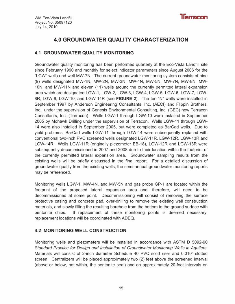
4.1 GROUNDWATER QUALITY MONITORING
Groundwater quality monitoring has been performed quarterly at the Eco-Vista Landfill site since February 1990 and monthly for select indicator parameters since August 2006 for the “LGW” wells and well MW-7N. The current groundwater monitoring system consists of nine (9) wells designated MW-1N, MW-2N, MW-3N, MW-4N, MW-5N, MW-7N, MW-8N, MW-10N, and MW-11N and eleven (11) wells around the currently permitted lateral expansion area which are designated LGW-1, LGW-2, LGW-3, LGW-4, LGW-5, LGW-6, LGW-7, LGW-8R, LGW-9, LGW-10, and LGW-14R (see FIGURE 2). The ten “N” wells were installed in September 1997 by Anderson Engineering Consultants, Inc. (AECI) and Flippin Brothers, Inc., under the supervision of Genesis Environmental Consulting, Inc. (GEC) now Terracon Consultants, Inc. (Terracon). Wells LGW-1 through LGW-10 were installed in September 2005 by Mohawk Drilling under the supervision of Terracon. Wells LGW-11 through LGW-14 were also installed in September 2005, but were completed as BarCad wells. Due to yield problems, BarCad wells LGW-11 through LGW-14 were subsequently replaced with conventional two-inch PVC screened wells designated LGW-11R, LGW-12R, LGW-13R and LGW-14R. Wells LGW-11R (originally piezometer EB-18), LGW-12R and LGW-13R were subsequently decommissioned in 2007 and 2008 due to their location within the footprint of the currently permitted lateral expansion area. Groundwater sampling results from the existing wells will be briefly discussed in the final report. For a detailed discussion of groundwater quality from the existing wells, the semi-annual groundwater monitoring reports may be referenced.
Monitoring wells LGW-1, MW-4N, and MW-5N and gas probe GP-1 are located within the footprint of the proposed lateral expansion area and, therefore, will need to be decommissioned at some point. Decommissioning will consist of removing the surface protective casing and concrete pad, over-drilling to remove the existing well construction materials, and slowly filling the resulting borehole from the bottom to the ground surface with bentonite chips. If replacement of these monitoring points is deemed necessary, replacement locations will be coordinated with ADEQ.
4.2 MONITORING WELL CONSTRUCTION
Monitoring wells and piezometers will be installed in accordance with ASTM D 5092-90 Standard Practice for Design and Installation of Groundwater Monitoring Wells in Aquifers.Materials will consist of 2-inch diameter Schedule 40 PVC solid riser and 0.010” slotted screen. Centralizers will be placed approximately two (2) feet above the screened interval (above or below, not within, the bentonite seal) and on approximately 20-foot intervals on
WM Eco-Vista LandfillProject No. 35097120 July 14, 2010
16
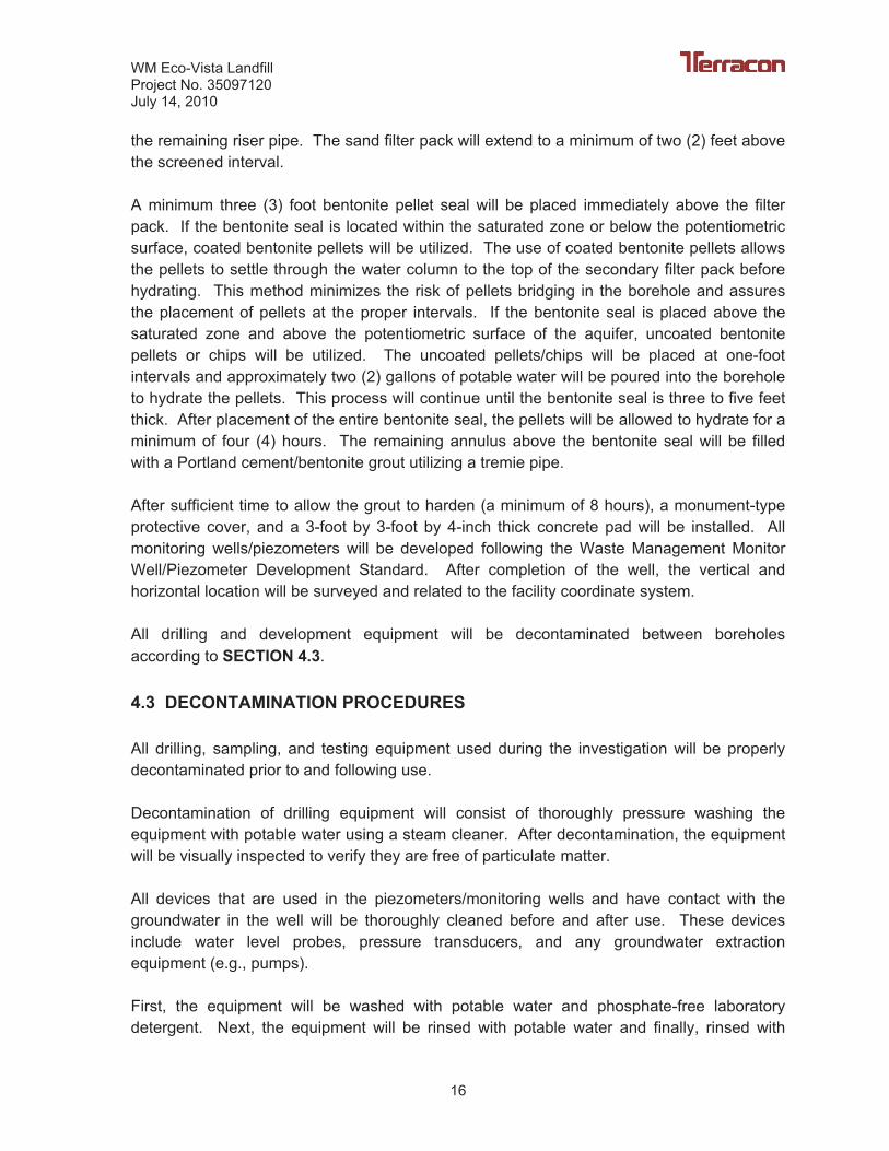
the remaining riser pipe. The sand filter pack will extend to a minimum of two (2) feet above the screened interval.
A minimum three (3) foot bentonite pellet seal will be placed immediately above the filter pack. If the bentonite seal is located within the saturated zone or below the potentiometric surface, coated bentonite pellets will be utilized. The use of coated bentonite pellets allows the pellets to settle through the water column to the top of the secondary filter pack before hydrating. This method minimizes the risk of pellets bridging in the borehole and assures the placement of pellets at the proper intervals. If the bentonite seal is placed above the saturated zone and above the potentiometric surface of the aquifer, uncoated bentonite pellets or chips will be utilized. The uncoated pellets/chips will be placed at one-foot intervals and approximately two (2) gallons of potable water will be poured into the borehole to hydrate the pellets. This process will continue until the bentonite seal is three to five feet thick. After placement of the entire bentonite seal, the pellets will be allowed to hydrate for a minimum of four (4) hours. The remaining annulus above the bentonite seal will be filled with a Portland cement/bentonite grout utilizing a tremie pipe.
After sufficient time to allow the grout to harden (a minimum of 8 hours), a monument-type protective cover, and a 3-foot by 3-foot by 4-inch thick concrete pad will be installed. All monitoring wells/piezometers will be developed following the Waste Management Monitor Well/Piezometer Development Standard. After completion of the well, the vertical and horizontal location will be surveyed and related to the facility coordinate system.
All drilling and development equipment will be decontaminated between boreholes according to SECTION 4.3.
4.3 DECONTAMINATION PROCEDURES
All drilling, sampling, and testing equipment used during the investigation will be properly decontaminated prior to and following use.
Decontamination of drilling equipment will consist of thoroughly pressure washing the equipment with potable water using a steam cleaner. After decontamination, the equipment will be visually inspected to verify they are free of particulate matter.
All devices that are used in the piezometers/monitoring wells and have contact with the groundwater in the well will be thoroughly cleaned before and after use. These devices include water level probes, pressure transducers, and any groundwater extraction equipment (e.g., pumps).
First, the equipment will be washed with potable water and phosphate-free laboratory detergent. Next, the equipment will be rinsed with potable water and finally, rinsed with

WM Eco-Vista LandfillProject No. 35097120 July 14, 2010
17
distilled water. After using the water level probe to measure each water level, a paper towel will be soaked with distilled water and the probe tape will be cleaned as it is reeled up.
WM Eco-Vista LandfillProject No. 35097120 July 14, 2010
18
5.0 REPORT PREPARATION
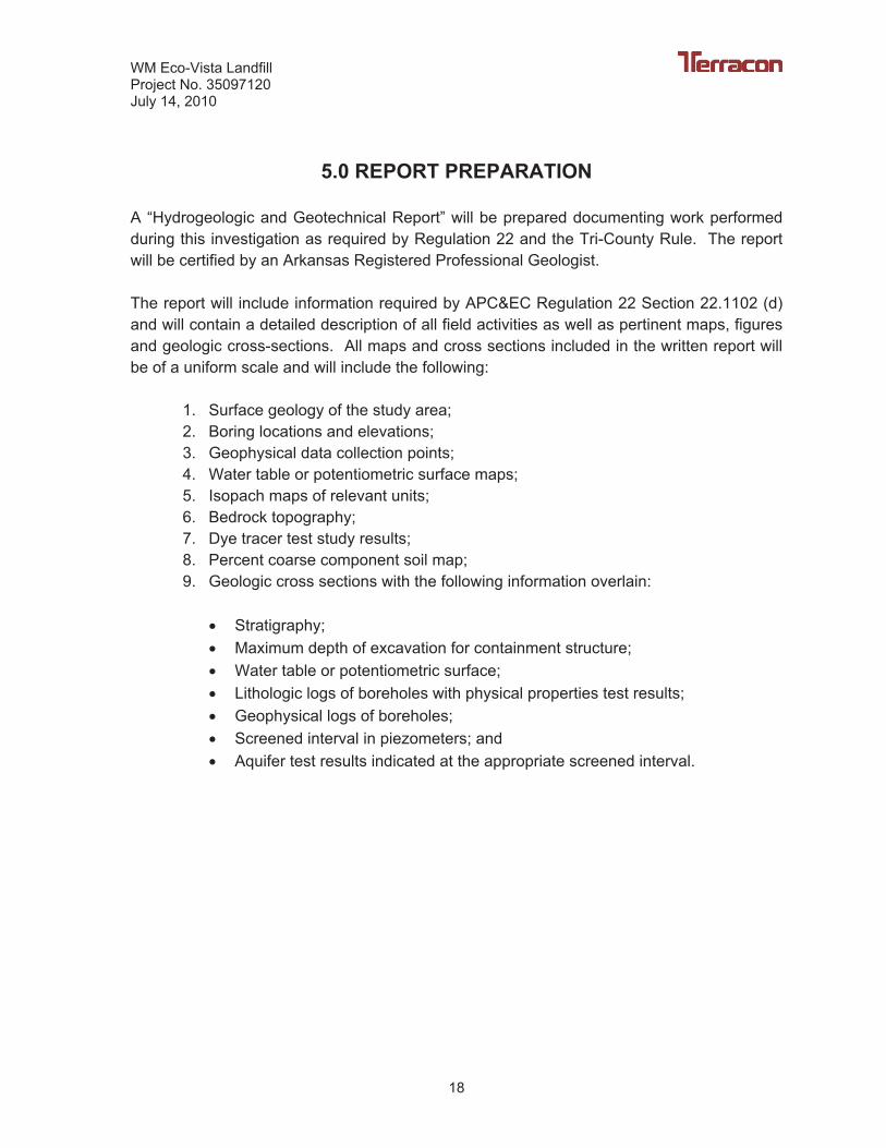
A “Hydrogeologic and Geotechnical Report” will be prepared documenting work performed during this investigation as required by Regulation 22 and the Tri-County Rule. The report will be certified by an Arkansas Registered Professional Geologist.
The report will include information required by APC&EC Regulation 22 Section 22.1102 (d) and will contain a detailed description of all field activities as well as pertinent maps, figures and geologic cross-sections. All maps and cross sections included in the written report will be of a uniform scale and will include the following:
1. Surface geology of the study area; 2. Boring locations and elevations; 3. Geophysical data collection points; 4. Water table or potentiometric surface maps; 5. Isopach maps of relevant units; 6. Bedrock topography; 7. Dye tracer test study results; 8. Percent coarse component soil map; 9. Geologic cross sections with the following information overlain:
� Stratigraphy; � Maximum depth of excavation for containment structure; � Water table or potentiometric surface; � Lithologic logs of boreholes with physical properties test results; � Geophysical logs of boreholes; � Screened interval in piezometers; and � Aquifer test results indicated at the appropriate screened interval.
WM Eco-Vista LandfillProject No. 35097120 July 14, 2010
19
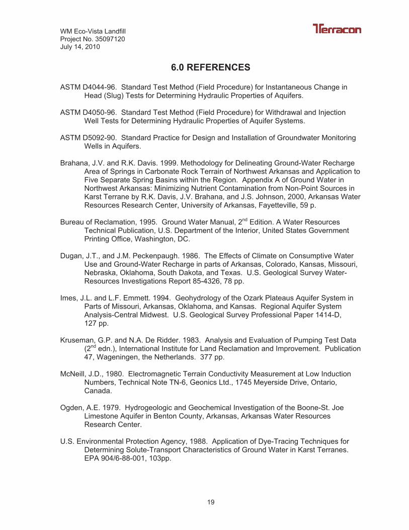
6.0 REFERENCES
ASTM D4044-96. Standard Test Method (Field Procedure) for Instantaneous Change in Head (Slug) Tests for Determining Hydraulic Properties of Aquifers.
ASTM D4050-96. Standard Test Method (Field Procedure) for Withdrawal and Injection Well Tests for Determining Hydraulic Properties of Aquifer Systems.
ASTM D5092-90. Standard Practice for Design and Installation of Groundwater Monitoring Wells in Aquifers.
Brahana, J.V. and R.K. Davis. 1999. Methodology for Delineating Ground-Water Recharge Area of Springs in Carbonate Rock Terrain of Northwest Arkansas and Application to Five Separate Spring Basins within the Region. Appendix A of Ground Water in Northwest Arkansas: Minimizing Nutrient Contamination from Non-Point Sources in Karst Terrane by R.K. Davis, J.V. Brahana, and J.S. Johnson, 2000, Arkansas Water Resources Research Center, University of Arkansas, Fayetteville, 59 p.
Bureau of Reclamation, 1995. Ground Water Manual, 2nd Edition. A Water Resources Technical Publication, U.S. Department of the Interior, United States Government Printing Office, Washington, DC.
Dugan, J.T., and J.M. Peckenpaugh. 1986. The Effects of Climate on Consumptive Water Use and Ground-Water Recharge in parts of Arkansas, Colorado, Kansas, Missouri, Nebraska, Oklahoma, South Dakota, and Texas. U.S. Geological Survey Water-Resources Investigations Report 85-4326, 78 pp.
Imes, J.L. and L.F. Emmett. 1994. Geohydrology of the Ozark Plateaus Aquifer System in Parts of Missouri, Arkansas, Oklahoma, and Kansas. Regional Aquifer System Analysis-Central Midwest. U.S. Geological Survey Professional Paper 1414-D,127 pp.
Kruseman, G.P. and N.A. De Ridder. 1983. Analysis and Evaluation of Pumping Test Data (2nd edn.), International Institute for Land Reclamation and Improvement. Publication 47, Wageningen, the Netherlands. 377 pp.
McNeill, J.D., 1980. Electromagnetic Terrain Conductivity Measurement at Low Induction Numbers, Technical Note TN-6, Geonics Ltd., 1745 Meyerside Drive, Ontario, Canada.
Ogden, A.E. 1979. Hydrogeologic and Geochemical Investigation of the Boone-St. Joe Limestone Aquifer in Benton County, Arkansas, Arkansas Water Resources Research Center.
U.S. Environmental Protection Agency, 1988. Application of Dye-Tracing Techniques for Determining Solute-Transport Characteristics of Ground Water in Karst Terranes. EPA 904/6-88-001, 103pp.

WM Eco-Vista LandfillProject No. 35097120 July 14, 2010
20
U.S. Environmental Protection Agency, 1993. Subsurface Characterization and Monitoring Techniques: A Desk Reference Guide. EPA 625-R-93-003, 448 pp.

FIGURES