hydrology training series module 111 – reservoir … training series . module 111 – reservoir...
TRANSCRIPT
Hydrology Training Series
Module 111 – Reservoir Flood Routing
Study Guide

Preface
This module consists of a study guide that provides a brief overview of reservoir flood routing.
Proceed through this module at your own pace. Be sure you completely understand each section before moving on. If you have questions or need help, please request assistance from your supervisor. If your supervisor cannot clear up your problems, he/she will contact the state-appointed resource person. The resource person is familiar with the material and should be able to answer any questions you may have.
Be sure to write out your answers to the included activities. This will help to reinforce your learning. After completing each activity, compare your answers with the included solution.
Acknowledgment
The design and development of this training module is the result of a concentrated effort by practicing engineers in the Soil Conservation Service (SCS). The contributions from many technical and procedural reviews have helped make this module one that will provide needed knowledge of hydrology and hydraulics to SCS employees
Module Description Objectives Upon completion of this module, the participant will be able to:
1. List the types of routing.
2. List the factors that affect flood routing.
3. Develop a stage-storage discharge relationship for a small structure.
4. Use the Engineering Field Manual shortcut flood routing procedure to design small structures.
5. Use Technical Release 55 shortcut flood routing procedure to design small structures.
The participant should be able to perform at ASK Level 3 (Perform with supervision) after completing this module. ~
Prerequisites Modules 101 - Introduction to Hydrology and 107 - Hydrographs
Length Participant should take as long as necessary to complete module. Training time for this module is approximately three hours.
Who May Take the Module
This module is intended for all SCS personnel who use reservoir flood routing procedures.
Method of Completion This module is self-study, but the state or NTC should select a resource person to answer any questions that the participant's supervisor cannot handle.
Content This module presents factors affecting flood routing, developing stage-storage relationships, and a shortcut storage routing method.
Introduction
In this module you will be introduced to flood routing as it is used in the Soil Conservation Service. You will be able to list the factors affecting flood routing and learn how to develop a stage-storage discharge relationship for a small structure. In addition, you win be shown how the Engineering Field Manual (EFM) and Technical Release-55 CTR-55) use a shortcut flood routing procedure to design small structures.
In order to satisfactorily use the procedures covered in this module, you may need additional training. This module should give you a thorough understanding of reservoir flood routing, but you will need additional experience and supervision before doing them on your own.
Types of Routing
Flood routing is the process of determining the timing and shape of a flood wave. In a reservoir, this is done by accounting for the storage available in the reservoir, whereas in a channel, the flood wave is observed at successive
points along a river. Reservoir and channel flood routing are the two types of routing that will be considered.
Reservoir
In a reservoir, the storage and outflow rate are interdependent. For example, when the outflow rate is less than the inflow rate, water is temporarily stored in the reservoir. The maximum stage of water occurs when the outflow and inflow rates are equal. Then, as the inflow reduces, the reservoir will begin to drain and the stage will reduce. Reservoir routing methods can be used when the outflow capacity is less than the inflow capacity and when the reservoir storage can be computed. Examples include farm ponds, storm water detention basins, and flood water retarding reservoirs. A road culvert or terrace is often a good example of this condition if there is a significant amount of storage upstream of the culvert or terrace.
For reservoir routing, the water surface is assumed to be level in the reservoir at all times. Depending upon the procedure, reservoir routing procedures can be used to obtain the maximum height of water in a reservoir, the maximum discharge through the spillway, or the complete outflow hydro graph. .
The principle of continuity of fluid flow is used to determine the equation for reservoir routing. The continuity equation is concerned with the conservation of mass. For a given time interval, the volume of inflow minus the volume of outflow equals the change in volume of storage.
Channel
The physical process in channels is the same as in reservoirs; however, storage is not a function of outflow alone. The movement of flood waves down natural streams may be described in terms of translation and reservoir effects. Translation involves maintaining the same hydrograph shape as the flood wave moves downstream. The reservoir effect involves use of valley storage to reduce the peak flow and change the shape ofthe hydrograph. As a result, the water surface is not always parallel to the bottom of the channel. An iterative process with the inflow hydro graph as an additional variable is usually used to perform the routing. This module will not deal with
channel routing.
Factors that Affect Flood Routing
Storage Capacity
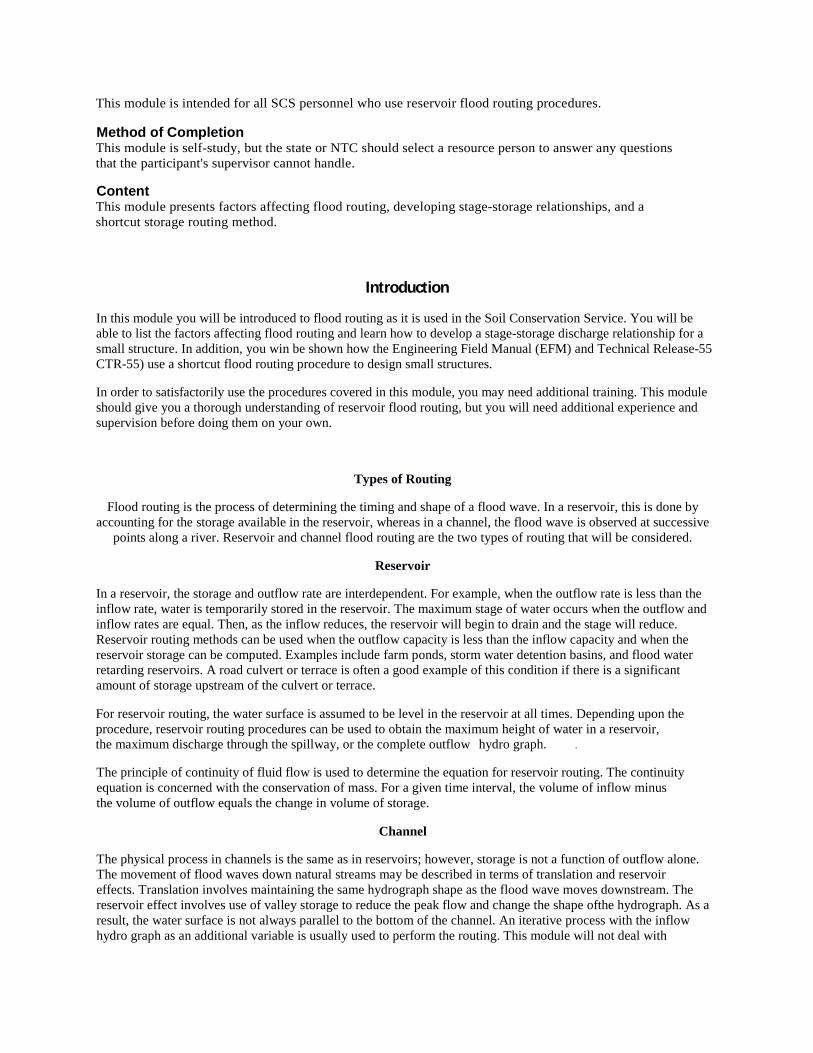
As inflow to the reservoir increases, the depth and resultant volume of water in storage increases. An equal amount of water is released from storage as the inflow decreases. The' storage characteristics cause the reservoir effect of reducing the peak flow and changing the shape of the hydrograph. The time base of the flood wave moving through the reservoir is increased. This effect is called attenuation.
The storage characteristics of the reservoir need to be defined for flood routing. The elevation or stage-storage relationship (Figure 1) obtained from one of the two procedures described below provides the reservoir storage capacity for use in routing.
Elevation-surface Area Method
A preferred method for estimating storage capacity is to compute the surface area of the reservoir at selected elevations. This method requires a topographic map of the reservoir. The advantage of this procedure is its accuracy. The assumption of straight streams and valleys does not need to be made.
With the actual surface area computed for each selected elevation, the incremental storage volume from the midpoint of one contour interval to the midpoint of the next lower contour interval can be computed. The incremental storage volumes are then accumulated to obtain the elevation storage relationship for the reservoir.
Cross Section-end Area Method
Stream valley cross sections can be surveyed at selected points in the reservoir area. The end area of each cross section can be computed at selected elevations. The end area can be multiplied by the horizontal distance between cross sections to obtain the storage volume at each of the selected elevations. The disadvantage of this procedure is the required assumption of a straight stream and valley, hardly a common natural occurrence.
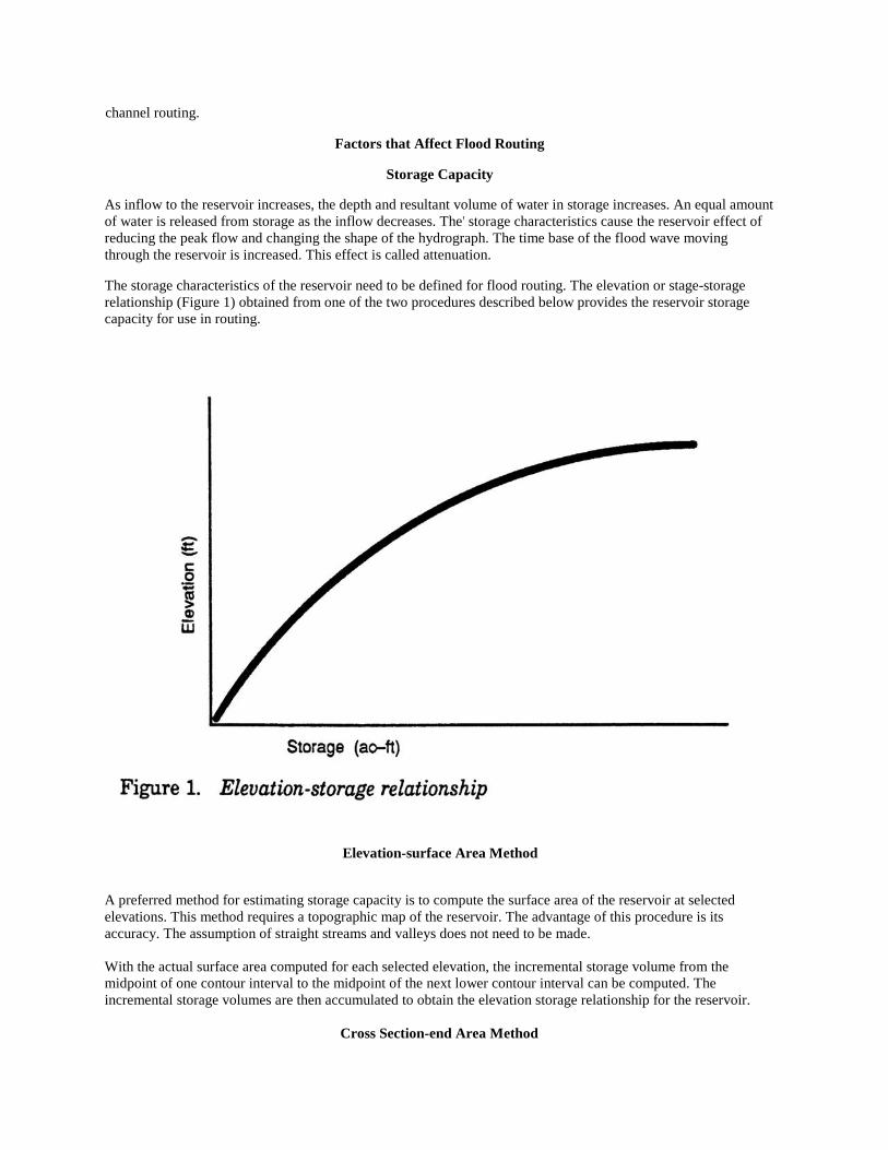
Discharge Capacity The relationship between the elevation of the water surface at the inlet to the control and the discharge through the control is commonly called the elevation or stage-discharge curve. Often the head or height of the water above the invert of the inlet is used instead of the actual elevation. In this case, the term "head-discharge curve" is used. (Figure 2).
Control structure or cross section
The outflow of a reservoir is determined by the flow capacity of the spillway of the control structure. For a stream reach, the flow capacity of the cross section at the downstream end of the reach determines the flow capacity.
Size and condition of spillway
The size of the spillway determines the flow area. The condition of the spillway determines, in large part, the velocity of the flow. A rough or irregular condition will reduce the velocity, while a smooth condition will allow a higher velocity.
Tailwater condition
The elevation of the water surface at the outlet of a spillway is commonly called the tail water condition. A high
tailwater condition restricts the flow through the spillway; therefore, it is important to know the tail water condition before computing the capacity of the spillway.
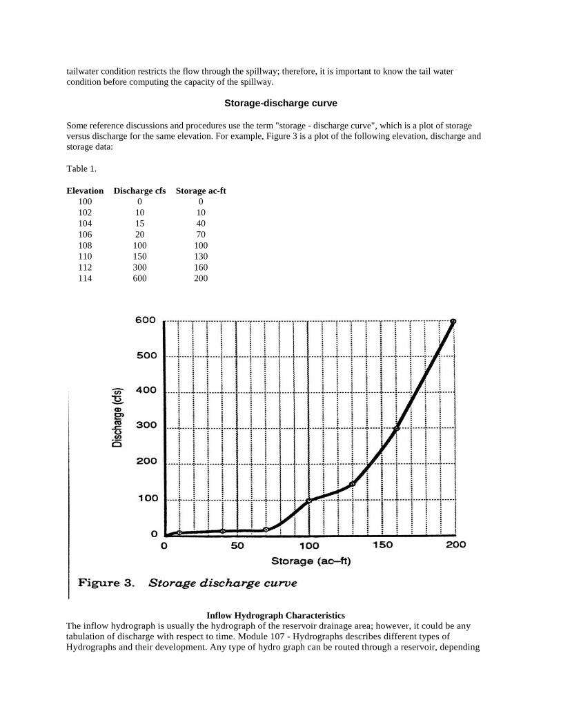
Storage-discharge curve
Some reference discussions and procedures use the term "storage - discharge curve", which is a plot of storage versus discharge for the same elevation. For example, Figure 3 is a plot of the following elevation, discharge and storage data: Table 1. Elevation Discharge cfs Storage ac-ft
100 0 0 102 10 10 104 15 40 106 20 70 108 100 100 110 150 130 112 300 160 114 600 200
Inflow Hydrograph Characteristics The inflow hydrograph is usually the hydrograph of the reservoir drainage area; however, it could be any tabulation of discharge with respect to time. Module 107 - Hydrographs describes different types of Hydrographs and their development. Any type of hydro graph can be routed through a reservoir, depending

on the purpose of routing. For example, a design hydrograph would usually be used to design a dam. To determine the performance of a reservoir should a historical storm reoccur, a natural hydrograph would be used.
Volume of runoff The volume of runoff is the total amount of excess rainfall or snowmelt that flows into the reservoir from a given event. It is also the area under the inflow hydrograph,
Runoff distribution The runoff distribution is the variation of the runoff over time. It is usually tabulated as accumulated runoff depths, at a selected time increment.
Intensity Runoff intensity is merely the rate at which runoff occurs for a specified period of time. It is important because the reservoir starts to fill when the runoff exceeds the outflow rate.
Duration The duration of runoff is the period of time that runoff occurs. If it is for an entire storm event, it is referred to as the storm duration. The storm duration is important for two reasons. First, it is a major factor in the volume of runoff flowing into the reservoir. Second, a given storm will produce a different duration of runoff, depending upon the watershed characteristics.
Initial Routing Elevation
The initial routing elevation must be determined prior to routing a hydrograph through a reservoir. This elevation represents the lowest elevation at which water can be stored before and during a storm event. The major factors to consider in determining the initial routing elevation are the permanent pool, the aerated sediment storage, and the baseflow.
Permanent pool The permanent pool is actually a misnomer. Few conditions related to nature in general and hydrology in particular are permanent. Nevertheless, the term is commonly used. Usually it refers to the pool formed by the principal spillway. The principal spillway is defined by TR-60 as the lowest ungated spillway designed to convey water from the reservoir at predetermined rates. Permanent storage occurs below the lowest ungated outlet.
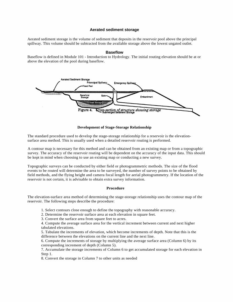
Three uses of storage, as shown in Figure 4, are the following;
l. Submerged sediment storage - The volume of reservoir space allotted to the accumulation of sediment submerged below the principal spillway crest during the life of the structure.
2. Beneficial use storage - The volume of reservoir space below the principal spillway crest allotted for such uses as recreation, fish and wildlife, or irrigation.
3. Dead storage - A nebulous term that usually means the volume of reservoir space below the principal spillway's lowest ungated outlet. Dead storage generally refers to storage that is not available for a beneficial use or that cannot be drained
Aerated sediment storage
Aerated sediment storage is the volume of sediment that deposits in the reservoir pool above the principal spillway. This volume should be subtracted from the available storage above the lowest ungated outlet.
Baseflow Baseflow is defined in Module 101 - Introduction to Hydrology. The initial routing elevation should be at or above the elevation of the pool during baseflow.
Development of Stage-Storage Relationship
The standard procedure used to develop the stage-storage relationship for a reservoir is the elevation-surface area method. This is usually used when a detailed reservoir routing is performed.
A contour map is necessary for this method and can be obtained from an existing map or from a topographic survey. The accuracy of the reservoir routing will be dependent on the accuracy of the input data. This should be kept in mind when choosing to use an existing map or conducting a new survey. Topographic surveys can be conducted by either field or photogrammetric methods. The size of the flood events to be routed will determine the area to be surveyed, the number of survey points to be obtained by field methods, and the flying height and camera focal length for aerial photogrammetry. If the location of the reservoir is not certain, it is advisable to obtain extra survey information.
Procedure The elevation-surface area method of determining the stage-storage relationship uses the contour map of the reservoir. The following steps describe the procedure: 1. Select contours close enough to define the topography with reasonable accuracy. 2. Determine the reservoir surface area at each elevation in square feet. 3. Convert the surface area from square feet to acres.
4. Compute the average surface area for the vertical increment between current and next higher tabulated elevations. 5. Tabulate the increments of elevation, which become increments of depth. Note that this is the difference between the elevations on the current line and the next line. 6. Compute the increments of storage by multiplying the average surface area (Column 6) by its corresponding increment of depth (Column 5). 7. Accumulate the storage increments of Column 6 to get accumulated storage for each elevation in Step 1. 8. Convert the storage in Column 7 to other units as needed

Example This example shows part of the computations used to develop Table 1. The drainage area of the reservoir is 8 square miles.
1. Select the representative contour interval of 2 ft. The contour interval was changed because the reservoir side slope increased with elevation. As the side slope increases, the interval can increase and maintain the same general accuracy.
2. For elevation 574 in the sample reservoir, the surface area measured on the contour map is
1,180,000 ft2. 3. Dividing 1,180,000 ft2 by 43,560 ft3/ac yields 27.09 ac surface area.
Elevation (ft)
Surface Area (ft2)
Surface Area (ac)
Average Surface
Area (ac)
Change in Depth (ft)
Change in Storage (ac-ft)
Storage (ac-ft)
Storage (in)
(1) (2) (3) (4) (5) (6) (7) (8) 570 0 0 0 0 0 0 0 572 420,000 9.64 4.82 2 9.64 9.64 0.02 574 1,180,000 27.09 18.37 2 36.74 46.38 0.11 576 2,374,000 54.50 40.80 2 81.60 127.98 0.30 580 3,866,000 88.75 71.63 4 286.52 414.50 0.97 585 5,427,000 124.59 106.67 5 533.35 947.85 2.22 590 7,954,000 182.60 153.60 5 768.00 1715.85 4.02 595 9,961,000 228.67 205.64 5 1028.20 3994.10 9.37
4. Add the surface area for elevations 574 and 572 and divide the result by 2 to obtain the average
surface area: (27.09 ac + 9.64 ac)/2 = 18.37 ac 5. Subtract elevation 572 from 574 to yield 2 ft incremental depth.
6. Multiply Column 4 by Column 5 to obtain the incremental storage: (18.37 ac) (2 ft) =36.74 ac-ft 7. Add Column 6 to the previous tabulation in Column 6 to obtain the storage at elevation 574:
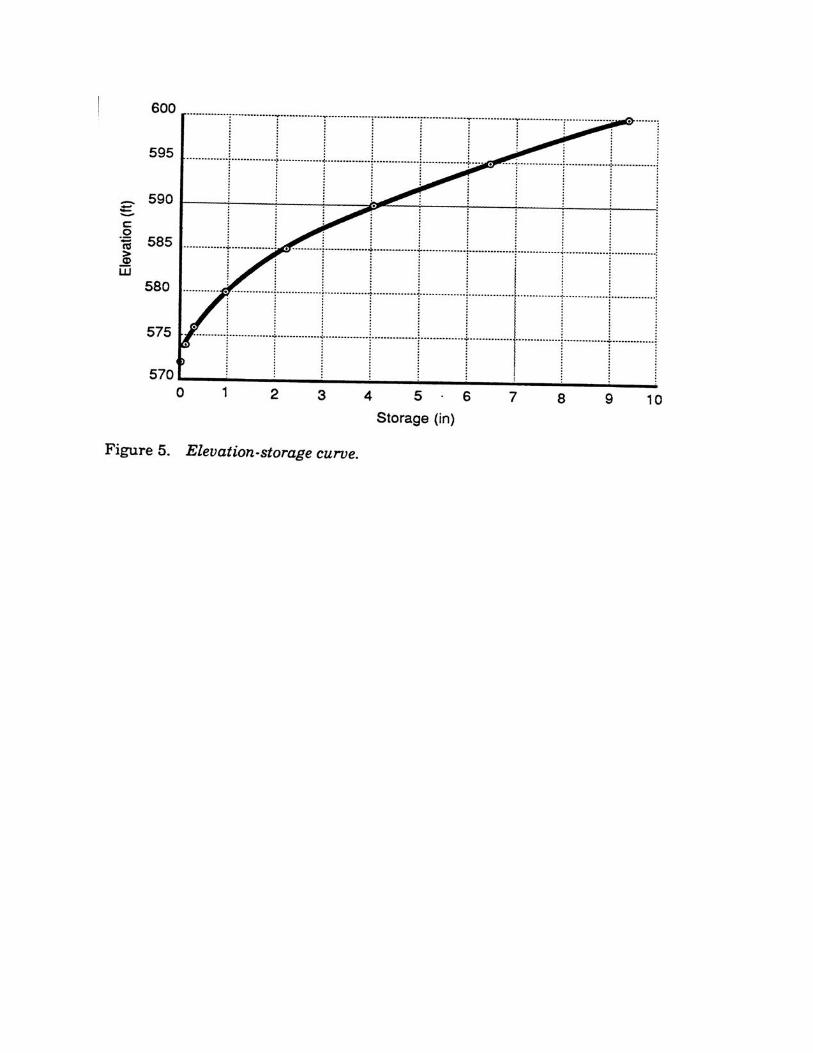
36.74 ac-ft + 9.64 ac-ft = 46.38 ac-ft 8. One inch depth covering one square mile of drainage area is equal to 53.3 ac-ft. Dividing 46.38
ac-ft by 53.3 (ac-ft/mi2)/in, and dividing that result by 8 mi2 yields 0.11 inc of storage. [{46.38 ac-ft}/ ((53.3 ac-ft/mi20/in)]/8mi2 = 0.11 in
The relationship between data in column 1 and 8 is plotted in Figure 5.
Engineering Field Manual Method
A method for approximating the capacity of a pond without detailed survey information is described in EFM, Chapter 11. It can used when only a reasonable estimate of pond capacity is needed, such as to determine if the water stored in a farm pond is adequate for its intended uses.
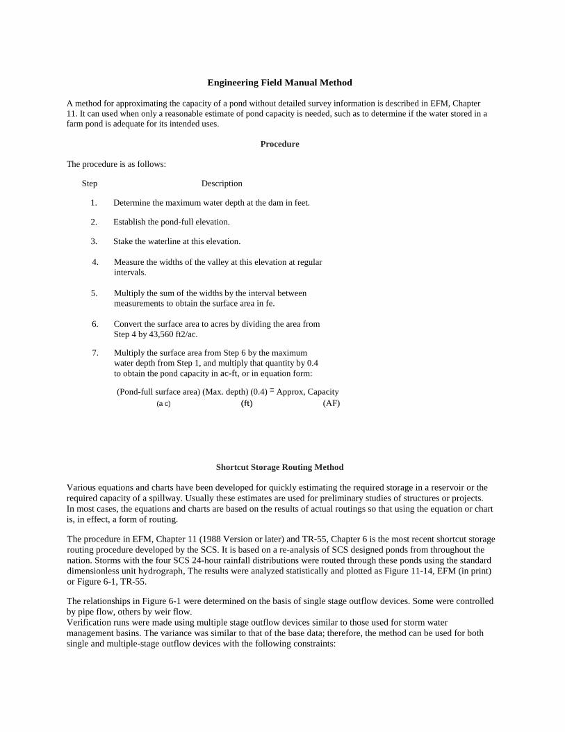
Procedure The procedure is as follows:
Step Description
1. Determine the maximum water depth at the dam in feet.
2. Establish the pond-full elevation.
3. Stake the waterline at this elevation.
4. Measure the widths of the valley at this elevation at regular intervals.
5. Multiply the sum of the widths by the interval between measurements to obtain the surface area in fe.
6. Convert the surface area to acres by dividing the area from Step 4 by 43,560 ft2/ac.
7. Multiply the surface area from Step 6 by the maximum water depth from Step 1, and multiply that quantity by 0.4 to obtain the pond capacity in ac-ft, or in equation form:
(Pond-full surface area) (Max. depth) (0.4) = Approx, Capacity (a c) (ft) (AF)
Shortcut Storage Routing Method Various equations and charts have been developed for quickly estimating the required storage in a reservoir or the required capacity of a spillway. Usually these estimates are used for preliminary studies of structures or projects. In most cases, the equations and charts are based on the results of actual routings so that using the equation or chart is, in effect, a form of routing.
The procedure in EFM, Chapter 11 (1988 Version or later) and TR-55, Chapter 6 is the most recent shortcut storage routing procedure developed by the SCS. It is based on a re-analysis of SCS designed ponds from throughout the nation. Storms with the four SCS 24-hour rainfall distributions were routed through these ponds using the standard dimensionless unit hydrograph, The results were analyzed statistically and plotted as Figure 11-14, EFM (in print) or Figure 6-1, TR-55.
The relationships in Figure 6-1 were determined on the basis of single stage outflow devices. Some were controlled by pipe flow, others by weir flow. Verification runs were made using multiple stage outflow devices similar to those used for storm water management basins. The variance was similar to that of the base data; therefore, the method can be used for both single and multiple-stage outflow devices with the following constraints:
1. Each stage requires a design storm and a computation of the storage required for it.
2. The discharge of the upper stages) includes the discharge of the lower stages(s).
The following limitations should be noted:
1. The routing method is less accurate as the qo/qi ratio approaches the limits shown in Figure 6-1, TR-55.
2. The procedure should not be used if an error in storage of 25 percent cannot be tolerated.
The following factors are needed when using the method described in TR-55:
1. Vr = volume of runoff (inflow hydrograph)
2. SCS design rainfall distribution Figure B-2, TR-55 shows the approximate geographic boundaries for the four SCS 24-hoUT rainfall distributions.
3. qi = peak inflow discharge
4. V s = temporary flood storage required The temporary flood storage is the factor for which this procedure provides the solution. However, it is essential input data if the peak outflow discharge is the desired answer. 5. qo = peak outflow discharge The peak outflow rate can be estimated by this procedure if the temporary flood storage is known.
The volume of runoff and peak outflow discharge must always be determined. Modules 105 - Runoff Computations and 106 - Peak Discharge describe the computation procedures for these factors.
If the temporary flood storage required is the unknown factor, the peak outflow discharge must be estimated. This may be a limiting downstream discharge or the flow capacity of a preselected spillway. In the case of storm water structures, the peak outflow is equal to the pre-urbanization stream flow. Thus, a reservoir is being used to mediate the impact of urbanization on the peak flow.
If the peak outflow rate required is the unknown factor, the temporary flood storage available must be estimated. Procedures for computing storage volume described above may be used, assuming a maximum temporary flood pool elevation.

Example 1 Given: In a urbanizing area the 10-year, pre-project flow is 200 cfs. The estimated urbanization lO-year flow is 320 cfs. The estimated runoff volume is 1.8 inches for this Type II rainfall distribution area.
Find: The storage requirement, Vs, needed to reduce the flow to pre-project conditions
Solution:
1. Determine the q,,/qi ratio
q,,/q, = 200 cfs/ 320 cfs = 0.625
2. Using Figure 6-1 (Appendix A), the storage ratio, Vs/Vr, is 0.23
3. Vs = (O.23)(Vr) = (0.23)(1.8 in) = 0.41 in
Example 2 Given: Same as Example 1
Find: The peak outflow discharge if the available storage was only 0.5 inches
Solution:
1. Vs/Vr = 0.5 in 11.8 in =- 0.28
2. From Figure 6-1, Clo/q; = 0.49
3. q. = (0.49)(q) = (0.49)(320 cfs) = 157 cfs

Summary
Now that you have completed Module 11, you should be able to list the factors affecting flood routing and have a good understanding of how (1) how to develop a stage-storage relationship for a small structure and (2) how to use the EFM and TR-55 shortcut flood routing procedure to design small structures. You will need more practice and maybe an additional training session before you become skilled in reservoir flood routing. Retain this Study Guide as a reference until you are satisfied that you have successfully mastered all the methods covered. It will provide an easy review at any time if you should encounter a problem. If you have had problems understanding this module or if you would like to take additional, related modules, contact your supervisor.

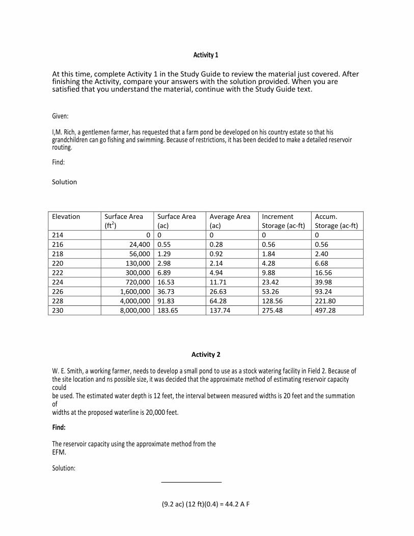
Activity 1
At this time, complete Activity 1 in the Study Guide to review the material just covered. After finishing the Activity, compare your answers with the solution provided. When you are satisfied that you understand the material, continue with the Study Guide text.
Given:
I,M. Rich, a gentlemen farmer, has requested that a farm pond be developed on his country estate so that his grandchildren can go fishing and swimming. Because of restrictions, it has been decided to make a detailed reservoir routing.
Find:
Solution
Elevation Surface Area (ft2)
Surface Area (ac)
Average Area (ac)
Increment Storage (ac-ft)
Accum. Storage (ac-ft)
214 0 216 24,400 218 56,000 220 130,000 222 300,000 224 720,000 226 1,600,000 228 4,000,000 230 8,000,000
Activity 2
W. E. Smith, a working farmer, needs to develop a small pond to use as a stock watering facility in Field 2. Because of the site location and ns possible size, it was decided that the approximate method of estimating reservoir capacity could be used. The estimated water depth is 12 feet, the interval between measured widths is 20 feet and the summation of widths at the proposed waterline is 20,000 feet.
Find:
The reservoir capacity using the approximate method from the EFM.
Solution:

Activity 3
A developer is planning to develop a 640 acre area near Ames, Iowa. The contributing drainage area for the proposed storm water management structure is 320 acres. The present condition 1 oo-year peak flow is 1200 cfs. ~ is estimated that with development, the 100-year peak flow would be 2800 cfs. The esiimated runoff volume for the developed condition is 3.18 inches.
Find:
The required storage in acre-feet
Solution:
Activity 4
Given:
A farmer in southwestern Pennsylvania is planning to build a farm pond. The drainage area above the ponds is 38.2 acres. The 1 O-year peak flow is 85 cfs, and the runoff volume is 2.7 inches.
Find:
The required storage in acre-feet if the outflow was limited to 40 cfs.
Solution:
Activity 1
At this time, complete Activity 1 in the Study Guide to review the material just covered. After finishing the Activity, compare your answers with the solution provided. When you are satisfied that you understand the material, continue with the Study Guide text.
Given:
I,M. Rich, a gentlemen farmer, has requested that a farm pond be developed on his country estate so that his grandchildren can go fishing and swimming. Because of restrictions, it has been decided to make a detailed reservoir routing.
Find:
Solution
Elevation Surface Area (ft2)
Surface Area (ac)
Average Area (ac)
Increment Storage (ac-ft)
Accum. Storage (ac-ft)
214 0 0 0 0 0 216 24,400 0.55 0.28 0.56 0.56 218 56,000 1.29 0.92 1.84 2.40 220 130,000 2.98 2.14 4.28 6.68 222 300,000 6.89 4.94 9.88 16.56 224 720,000 16.53 11.71 23.42 39.98 226 1,600,000 36.73 26.63 53.26 93.24 228 4,000,000 91.83 64.28 128.56 221.80 230 8,000,000 183.65 137.74 275.48 497.28
Activity 2
W. E. Smith, a working farmer, needs to develop a small pond to use as a stock watering facility in Field 2. Because of the site location and ns possible size, it was decided that the approximate method of estimating reservoir capacity could be used. The estimated water depth is 12 feet, the interval between measured widths is 20 feet and the summation of widths at the proposed waterline is 20,000 feet.
Find:
The reservoir capacity using the approximate method from the EFM.
Solution:
(9.2 ac) (12 ft)(0.4) = 44.2 A F

Activity 3
A developer is planning to develop a 640 acre area near Ames, Iowa. The contributing drainage area for the proposed storm water management structure is 320 acres. The present condition 1 oo-year peak flow is 1200 cfs. ~ is estimated that with development, the 100-year peak flow would be 2800 cfs. The esiimated runoff volume for the developed condition is 3.18 inches.
Find:
The required storage in acre-feet
Solution: 1. qo/qi = 1200 cfs/2800 cfs = 0.43.
2. Using Figure 6-1 (Appendix A)
Vs/Nr = 0.31
3. Vs = (0.31 )(3.18 in) = 0.995 in
Vs = (0.99 in)(1 fV12 in)(320 ac)
Vs = 26.4 ac-ft

Activity 4
Given:
A farmer in southwestern Pennsylvania is planning to build a farm pond. The drainage area above the ponds is 38.2 acres. The 1 O-year peak flow is 85 cfs, and the runoff volume is 2.7 inches.
Find:
The required storage in acre-feet if the outflow was limited to 40 cfs.
Solution:
1. qo/qi = 40 cfs/85 cfs = 0.47
2. . From Figure 6-1, Vs/Nr = 0.29
3. Vs = (0.29)(2.7 in) = 0.78 in
Vs = (0.78 in)(1 fV12 in)(38.2 ac)
Vs = 2.5 ac-tt