hydrostatic transmissions. 6.pdf · hydrostatic transmissions for vehicle propulsion a hydrostatic...
TRANSCRIPT
1
HYDROSTATIC TRANSMISSIONS
Fluid Power Circuits and Controls, John S.Cundiff, 2001
Introduction
Focus
The characteristics of hydrostatic transmission will be compared with mechanical transmissions.
2
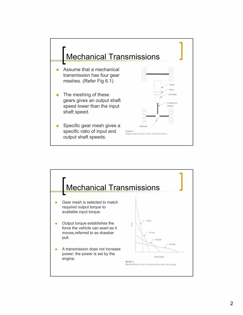
Mechanical TransmissionsAssume that a mechanical transmission has four gear meshes. (Refer Fig 6.1)
The meshing of these gears gives an output shaft speed lower than the input shaft speed.
Specific gear mesh gives a specific ratio of input and output shaft speeds.
Mechanical Transmissions
Gear mesh is selected to match required output torque to available input torque.
Output torque establishes the force the vehicle can exert as it moves,referred to as drawbar pull.
A transmission does not increase power; the power is set by the engine.
3
Mechanical Transmissions
An automatic transmission has a series of fixed gear ratios.
Depending on the design of transmission, these gear ratios each have their own unique clutch or combination of clutches.
When a given clutch is activated, the corresponding gear ratio is placed in the drive.
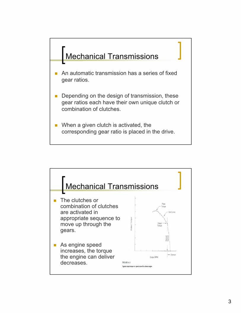
Mechanical TransmissionsThe clutches or combination of clutches are activated in appropriate sequence to move up through the gears.
As engine speed increases, the torque the engine can deliver decreases.
4
Mechanical Transmissions
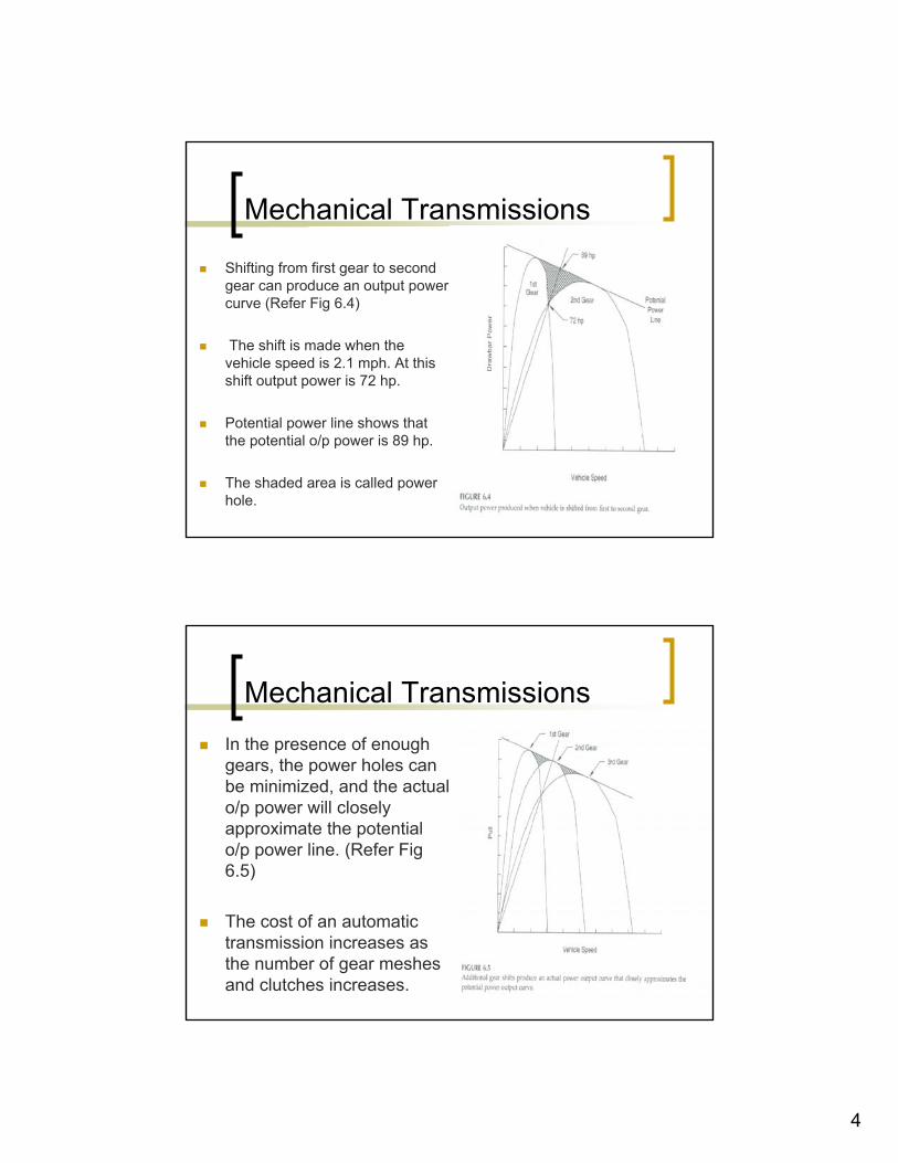
Shifting from first gear to second gear can produce an output power curve (Refer Fig 6.4)
The shift is made when the vehicle speed is 2.1 mph. At this shift output power is 72 hp.
Potential power line shows that the potential o/p power is 89 hp.
The shaded area is called power hole.
Mechanical TransmissionsIn the presence of enough gears, the power holes can be minimized, and the actual o/p power will closely approximate the potential o/p power line. (Refer Fig 6.5)
The cost of an automatic transmission increases as the number of gear meshes and clutches increases.

5
Mechanical Transmissions
A torque converter is placed between the engine and the automatic transmission to reduce the number of transmission shifts required.
Refer Fig 6.6
Torque converters have been designed to transmit hundreds of horsepower.
Mechanical Transmissions
Shift Control of Automatic Transmission
Performance of a direct-drive transmission with (six gears) is compared to a torque converter / automatic transmission with three shifts.
Torque converter “broadens” the power transfer bands with the three shifts such that the power line is equally as smooth as the power line produced with six shifts. (Refer Fig 6.9)
6
Mechanical Transmissions
A machine with a direct-drive transmission is the best choice when
High efficiency is needed to transfer maximum power possible.
The load is relatively constant, thus minimal shifting is needed.
Overloads are rare, thus engine stall protection is not needed.
Mechanical Transmissions
An automatic shift transmission is needed when
Load variability is high.
High pull is required at zero or low vehicle speed.
Engine stall protection is needed.
It is desirable to maintain a relatively constant engine speed.
7
Introduction to Hydrostatic Transmissions
A hydrostatic transmission is simply a pump and motor connected in a circuit.
Other components are added to obtain operating functions.
Introduction to Hydrostatic Transmissions
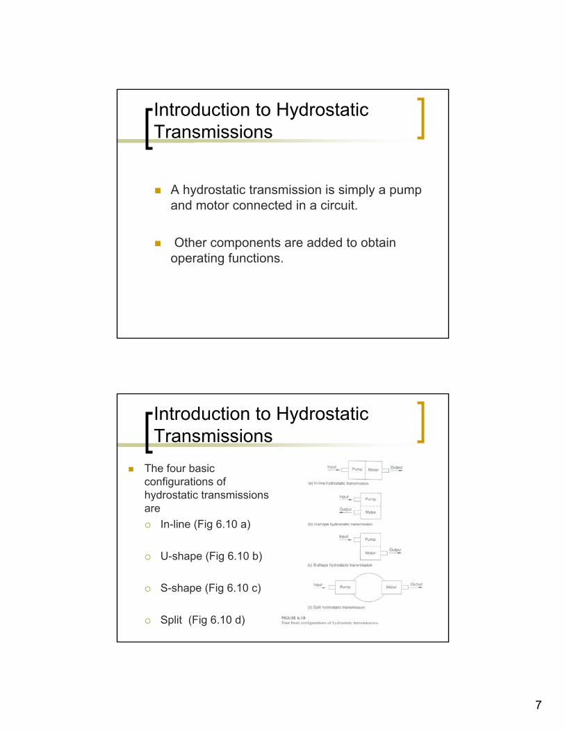
The four basic configurations of hydrostatic transmissions are
In-line (Fig 6.10 a)
U-shape (Fig 6.10 b)
S-shape (Fig 6.10 c)
Split (Fig 6.10 d)
8
Introduction to Hydrostatic Transmissions
Various pumps and motor designs can be paired together for the split configuration.
Manufacturers use the similar components to build the in-line, U-shape, and the S-shape configurations.
Hydraulic hose is available with a working pressure rating of 6000 psi.
Use of these hoses allows the split transmission to be operated at the max pressure rating of high-performance pumps and motors.
Introduction to Hydrostatic Transmissions
Advantage of Split transmission.
Pump/motor is mounted on a pump mount bolted directly to the engine. The motors will absorb some deflection caused by dynamic loads applied to the frame.
Flexible hoses between the pump and the motor(s), will absorb deflection caused by dynamic loads applied to the frame.
9
Hydrostatic Transmissions for Vehicle Propulsion
The mechanical transmission can be replaced with a hydrostatic transmission; all other components remain the same.
Pump o/p flow is increased by stroking the pump, thereby increasing the speed of the motor.
The vehicle can be speeded up and slowed down by moving the hand control that stokes the pump.
Rotation of the motor shaft can be reversed by moving the swash-plate control through the neutral position and displacing it in opposite direction.
Hydrostatic Transmissions for Vehicle Propulsion
The reverse position of the swash-plate causes fluid to flow in the opposite direction.
This causes the motor to turn in the opposite direction, thus reversing the vehicle.
Vehicle motion can be changed from forward to reverse with a simple hand movement.
10
Hydrostatic Transmissions for Vehicle Propulsion
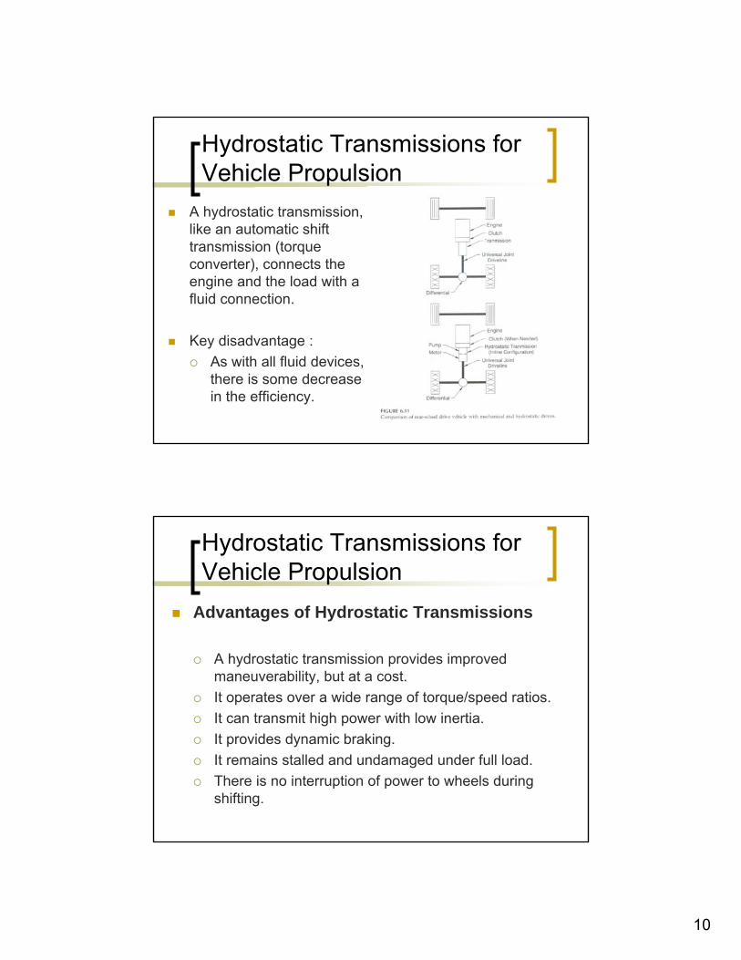
A hydrostatic transmission, like an automatic shift transmission (torque converter), connects the engine and the load with a fluid connection.
Key disadvantage : As with all fluid devices, there is some decrease in the efficiency.
Hydrostatic Transmissions for Vehicle Propulsion
Advantages of Hydrostatic Transmissions
A hydrostatic transmission provides improved maneuverability, but at a cost.It operates over a wide range of torque/speed ratios.It can transmit high power with low inertia.It provides dynamic braking.It remains stalled and undamaged under full load. There is no interruption of power to wheels during shifting.
11
Hydrostatic Transmissions for Vehicle Propulsion
Efficiency of a hydrostatic transmission is always lower than a discrete- gear transmission.
A discrete gear transmission will typically have an efficiency of 95% or greater.
Hydrostatic transmission has an efficiency of around 80%.
Some well designed units will have an efficiency slightly above 85%.
Different Configurations of Hydrostatic Transmissions to Propel Vehicles.
Hydrostatic transmission with Two Wheel Motors.
Wheel motors, mounted at both rear wheels eliminate the universal joint driveline, differential, and rear axle, with resultant cost and weight savings.
Because pump has low inertia, it is possible to start the engine with a direct-coupled pump.
Clutch is needed if cold starting is a major consideration.
12
Different Configurations of Hydrostatic Transmissions to Propel Vehicles.
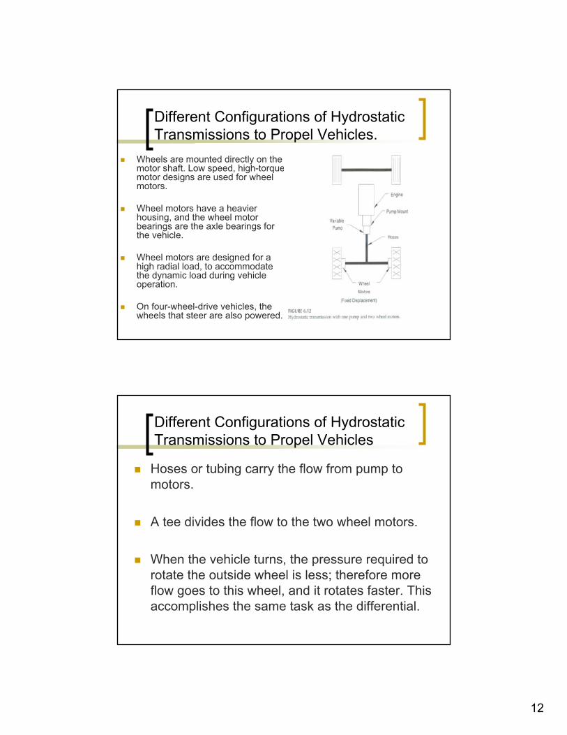
Wheels are mounted directly on the motor shaft. Low speed, high-torque motor designs are used for wheel motors.
Wheel motors have a heavier housing, and the wheel motor bearings are the axle bearings for the vehicle.
Wheel motors are designed for a high radial load, to accommodate the dynamic load during vehicle operation.
On four-wheel-drive vehicles, the wheels that steer are also powered.
Different Configurations of Hydrostatic Transmissions to Propel Vehicles
Hoses or tubing carry the flow from pump to motors.
A tee divides the flow to the two wheel motors.
When the vehicle turns, the pressure required to rotate the outside wheel is less; therefore more flow goes to this wheel, and it rotates faster. This accomplishes the same task as the differential.
13
Different Configurations of Hydrostatic Transmissions to Propel Vehicles
Speed obtained with a given flow is only one-half of the speed obtained with a single motor.
On the other hand, using two wheel motors provide twice the total wheel torque.
Different Configurations of Hydrostatic Transmissions to Propel Vehicles
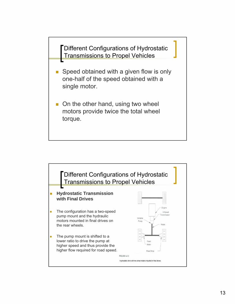
Hydrostatic Transmission with Final Drives
The configuration has a two-speed pump mount and the hydraulic motors mounted in final drives on the rear wheels.
The pump mount is shifted to a lower ratio to drive the pump at higher speed and thus provide the higher flow required for road speed.
14
Different Configurations of Hydrostatic Transmissions to Propel Vehicles
The final drive on the rear wheels is generally some type of planetary gear set.
One name given to this gear set is planetary wheel drive, and other names are wheel drive and power wheel.
Different Configurations of Hydrostatic Transmissions to Propel Vehicles
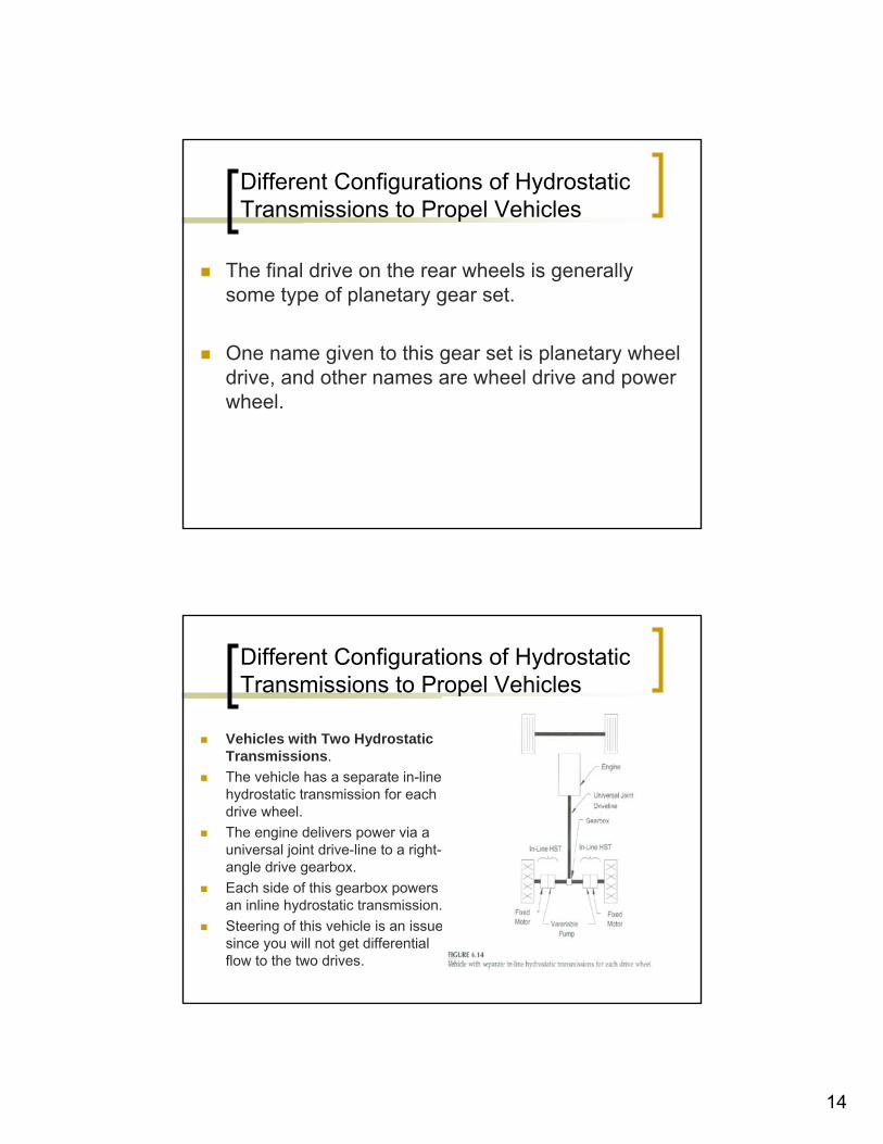
Vehicles with Two Hydrostatic Transmissions. The vehicle has a separate in-line hydrostatic transmission for each drive wheel. The engine delivers power via a universal joint drive-line to a right-angle drive gearbox. Each side of this gearbox powers an inline hydrostatic transmission.Steering of this vehicle is an issue since you will not get differential flow to the two drives.
15
Different Configurations of Hydrostatic Transmissions to Propel Vehicles
Typical application for this configuration:agricultural machine called windrower.
Cuts hays and rolls into a continuous pile known as a windrow. Cutting mechanism (header) is mounted in front of the drive wheels, which are the front wheels of the machine. The rear wheels are non-steered caster wheels.A mechanical linkage from the steering wheel to swash-plate control on both pumps.
Different Configurations of Hydrostatic Transmissions to Propel Vehicles
Straight-ahead travel: swash-plate on both pumps is set at the same position.
Steering wheel is turned: control on one side is pushed forward, control on the other side is pushed backward.
If steering is turned far enough, one pump swash-plate will be in full forward position, and one will be in full reverse position.
One drive wheel turns forward, and the other turns in reverse. Thus giving you a zero-turning radius.
16
Different Configurations of Hydrostatic Transmissions to Propel Vehicles
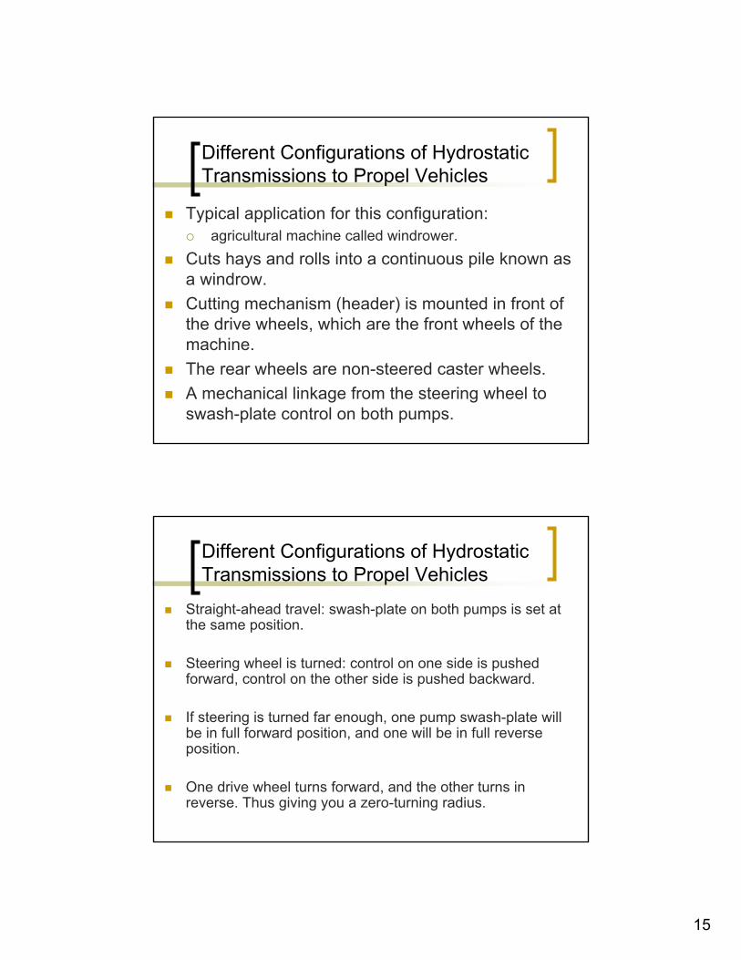
Vehicle shown has a separate split hydrostatic transmission for each drive wheel.
Does not have the universal joint drive line or gearbox.
Power is transferred via hoses rather than mechanically.
Different Configurations of Hydrostatic Transmissions to Propel Vehicles
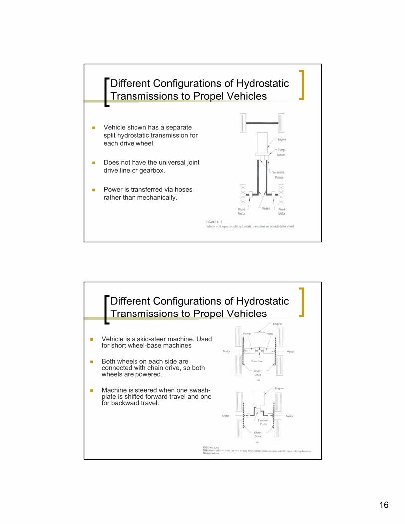
Vehicle is a skid-steer machine. Used for short wheel-base machines
Both wheels on each side are connected with chain drive, so both wheels are powered.
Machine is steered when one swash-plate is shifted forward travel and one for backward travel.
17
Different Configurations of Hydrostatic Transmissions to Propel Vehicles
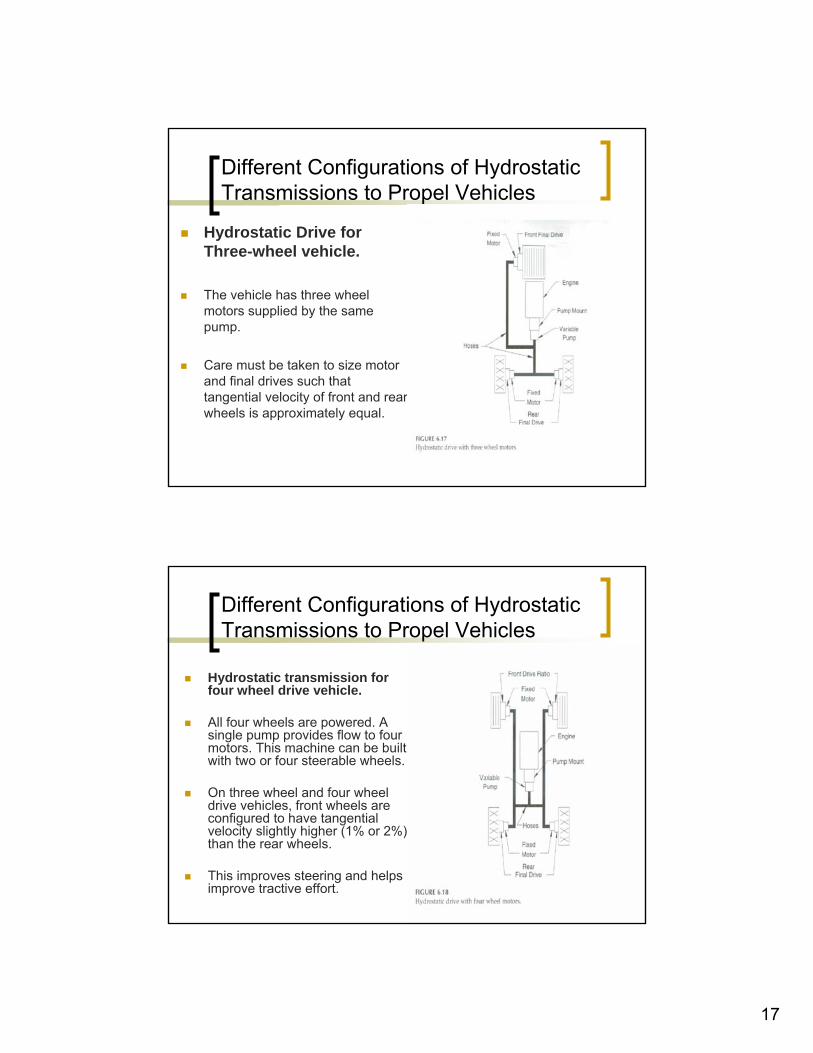
Hydrostatic Drive for Three-wheel vehicle.
The vehicle has three wheel motors supplied by the same pump.
Care must be taken to size motor and final drives such that tangential velocity of front and rear wheels is approximately equal.
Different Configurations of Hydrostatic Transmissions to Propel Vehicles
Hydrostatic transmission for four wheel drive vehicle.
All four wheels are powered. A single pump provides flow to four motors. This machine can be built with two or four steerable wheels.
On three wheel and four wheel drive vehicles, front wheels are configured to have tangential velocity slightly higher (1% or 2%) than the rear wheels.
This improves steering and helps improve tractive effort.
18
Classification of Hydrostatic Transmissions.
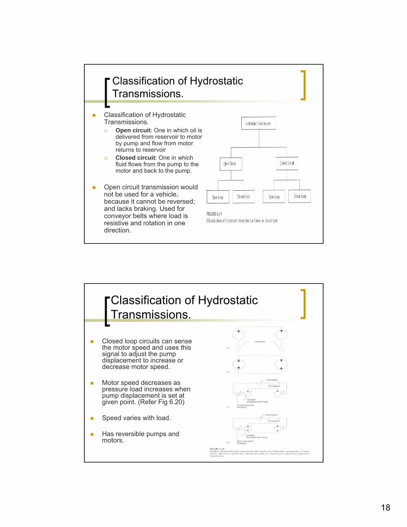
Classification of Hydrostatic Transmissions.
Open circuit: One in which oil is delivered from reservoir to motor by pump and flow from motor returns to reservoirClosed circuit: One in which fluid flows from the pump to the motor and back to the pump.
Open circuit transmission would not be used for a vehicle, because it cannot be reversed; and lacks braking. Used for conveyor belts where load is resistive and rotation in one direction.
Classification of Hydrostatic Transmissions.
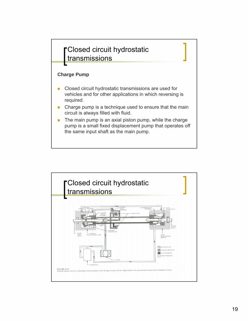
Closed loop circuits can sense the motor speed and uses this signal to adjust the pump displacement to increase or decrease motor speed.
Motor speed decreases as pressure load increases when pump displacement is set at given point. (Refer Fig 6.20)
Speed varies with load.
Has reversible pumps and motors.
19
Closed circuit hydrostatic transmissions
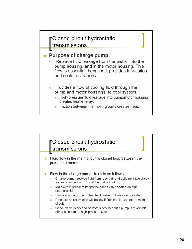
Charge Pump
Closed circuit hydrostatic transmissions are used for vehicles and for other applications in which reversing is required.Charge pump is a technique used to ensure that the main circuit is always filled with fluid. The main pump is an axial piston pump, while the charge pump is a small fixed displacement pump that operates off the same input shaft as the main pump.
Closed circuit hydrostatic transmissions
20
Closed circuit hydrostatic transmissions
Purpose of charge pump:Replace fluid leakage from the piston into the
pump housing, and in the motor housing. This flow is essential, because it provides lubrication and seals clearances.
Provides a flow of cooling fluid through the pump and motor housings, to cool system.
High-pressure fluid leakage into pump/motor housing creates heat energy.Friction between the moving parts creates heat.
Closed circuit hydrostatic transmissions
Fluid flow in the main circuit is closed loop between the pump and motor.
Flow in the charge pump circuit is as follows:Charge pump receives fluid from reservoir and delivers it two check values, one on each side of the main circuit. Main circuit pressure keeps the check valve seated on high-pressure side. Flow will occur through the check valve on low-pressure side.Pressure on return side will be low if fluid has leaked out of main circuit.Check valve is needed on both sides, because pump is reversible;either side can be high-pressure side.
21
Closed circuit hydrostatic transmissions
The required charge pump flow is the sum of fluid lost from the main circuit at both the pump and motor ends, plus the fluid required to cool the housings.
Closed circuit hydrostatic transmissions
Shuttle valve
For large hydrostatic transmissions, a shuttle valve is incorporated in the motor end.
Pressure on the high-pressure side shifts the spool of shuttle valves so that the fluid on the low pressure side has a pathway to a charge relief valve mounted in the end plate of the motor.
Fluid drops across this relief valve into the case of the motor where it combines with leakage flow and flows through drain line to pump, through the pump housing, and back to reservoir.
22
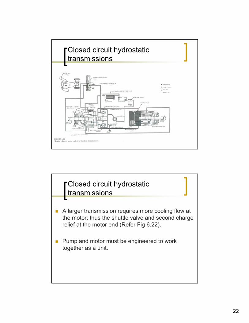
Closed circuit hydrostatic transmissions
Closed circuit hydrostatic transmissions
A larger transmission requires more cooling flow at the motor; thus the shuttle valve and second charge relief at the motor end (Refer Fig 6.22).
Pump and motor must be engineered to work together as a unit.
23
Closed circuit hydrostatic transmissions
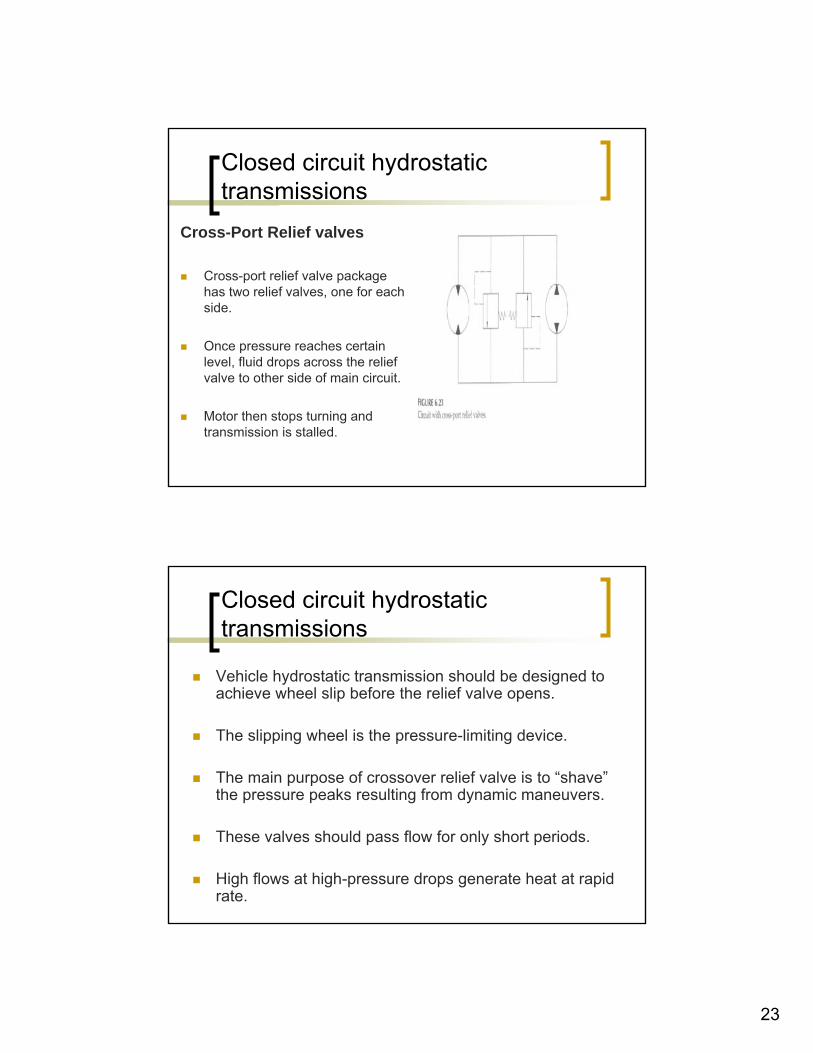
Cross-Port Relief valves
Cross-port relief valve package has two relief valves, one for each side.
Once pressure reaches certain level, fluid drops across the relief valve to other side of main circuit.
Motor then stops turning and transmission is stalled.
Closed circuit hydrostatic transmissions
Vehicle hydrostatic transmission should be designed to achieve wheel slip before the relief valve opens.
The slipping wheel is the pressure-limiting device.
The main purpose of crossover relief valve is to “shave” the pressure peaks resulting from dynamic maneuvers.
These valves should pass flow for only short periods.
High flows at high-pressure drops generate heat at rapid rate.
24
Closed circuit hydrostatic transmissions
A condition that opens the cross-port relief must be relieved quickly to prevent the transmission from overheating and being damaged.
Multipurpose valvesSome manufacturers supply a multipurpose valve that incorporatesseveral features into one valve.High-pressure reliefCheck valveBypass valve allows the vehicle to be towed.Pressure limiter destrokes the pump in response to excessive pressure.
Closed circuit, Closed-Loop hydrostatic transmissions
Hydrostatic transmission performance is governed by the characteristics of the pump and motor.
Suppose, a pump has a displacement of 1.925 in3/rev and is driven at a speed of 2400 rpm.
Theoretical flow is 1.925 in3/rev X 2400 rev/min = 20 GPM
231 in3/gal
25
Closed circuit, Closed-Loop hydrostatic transmissions
Motor used has a displacement of 1.925 in3/rev.
Motor speed is 20 gal/min X 231 in3/gal = 2400 GPM
1.925 in3
However, the pump volumetric efficiency at 1000psi is 0.90, so the actual pump flow is
20 X 0.90 = 18 GPM
Closed circuit, Closed-Loop hydrostatic transmissions
Flow to the motor is no longer 20 GPM but 18 GPM. If there is no leakage in the motor, the motor speed will be
18 gal/min X 231 in3/gal = 2160 rpm1.925 in3/rev
However, at 1000 psi the motor volumetric efficiency is 0.90. Actual motor output speed is
18 gal/min X 231 in3/gal X 0.90 = 1944 rpm1.925 in3/rev
26
Closed circuit, Closed-Loop hydrostatic transmissions
Input speed to the pump is 2400 rpm, and the achieved output speed from the motor is 1944 rpm.
Overall volumetric efficiency of HST is
1944 = 0.812400
Closed circuit, Closed-Loop hydrostatic transmissions
Another way of calculating this efficiency is to multiply the volumetric efficiency of pump times the volumetric efficiency of the motor.
0.9 X 0.9 = 0.81
Motor speed varies with pressure in a hydrostatic transmission.
It is beneficial to plot pump and motor performance curves on the same graph.
27
Closed circuit, Closed-Loop hydrostatic transmissions
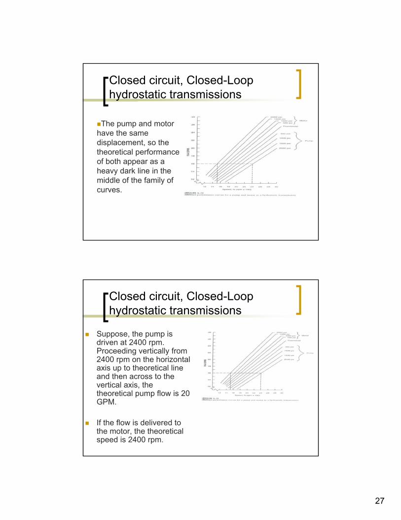
The pump and motor have the same displacement, so the theoretical performance of both appear as a heavy dark line in the middle of the family of curves.
Closed circuit, Closed-Loop hydrostatic transmissions
Suppose, the pump is driven at 2400 rpm. Proceeding vertically from 2400 rpm on the horizontal axis up to theoretical line and then across to the vertical axis, the theoretical pump flow is 20 GPM.
If the flow is delivered to the motor, the theoretical speed is 2400 rpm.
28
Closed circuit, Closed-Loop hydrostatic transmissions
Pump is driven at 2400 rpm and develops 2000 psi pressure.
What flow is delivered to the motor?Follow the dotted line up to the 2000 psi curve and then move horizontally to the vertical axis to read a pump flow of 16 GPM.
What is motor speed when this 16 GPM is delivered to motor?
Follow dotted curve from 16 GPM horizontally to the 2000 psi motor curve and then down to the horizontal axis to read the motor speed of 1530 rpm. If no pressure was developed, the motor speed would have been 2400 rpm. Actual speed is 1530 rpm, or 36% less.
Closed circuit, Closed-Loop hydrostatic transmissions
Servo-controlled pump
How it operates?Variable displacement axial piston pump When configured for servo control, this pump will have a control piston mounted in pump housing.When the control piston extends, it moves the swash plate to increase the amount of fluid pumped by the pistonsFlow of fluid to control piston is controlled with servo valve, and is called servo-controlled pump.
29
Closed circuit, Closed-Loop hydrostatic transmissions
Closed circuit, Closed-Loop hydrostatic transmissions
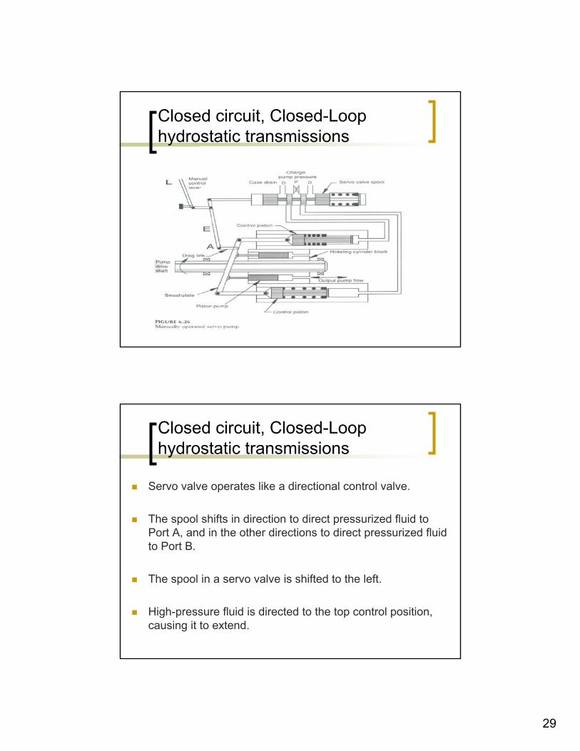
Servo valve operates like a directional control valve.
The spool shifts in direction to direct pressurized fluid to Port A, and in the other directions to direct pressurized fluid to Port B.
The spool in a servo valve is shifted to the left.
High-pressure fluid is directed to the top control position, causing it to extend.
30
Closed circuit, Closed-Loop hydrostatic transmissions
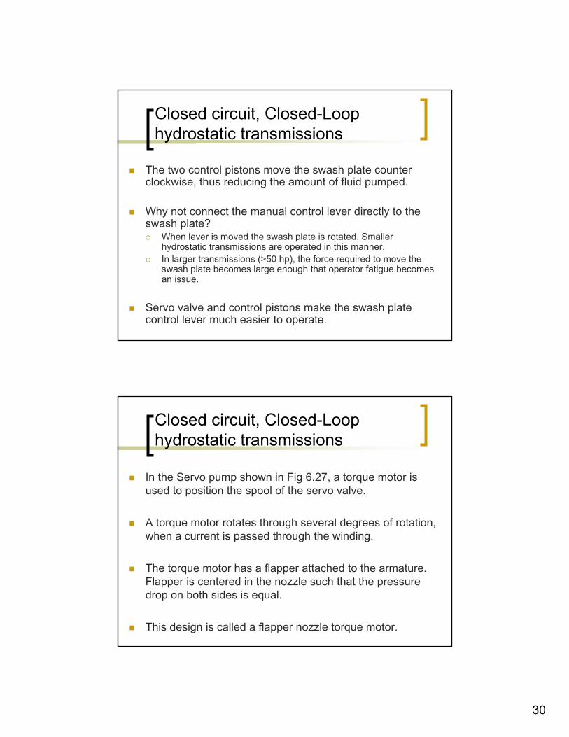
The two control pistons move the swash plate counter clockwise, thus reducing the amount of fluid pumped.
Why not connect the manual control lever directly to the swash plate?
When lever is moved the swash plate is rotated. Smaller hydrostatic transmissions are operated in this manner.In larger transmissions (>50 hp), the force required to move theswash plate becomes large enough that operator fatigue becomes an issue.
Servo valve and control pistons make the swash plate control lever much easier to operate.
Closed circuit, Closed-Loop hydrostatic transmissions
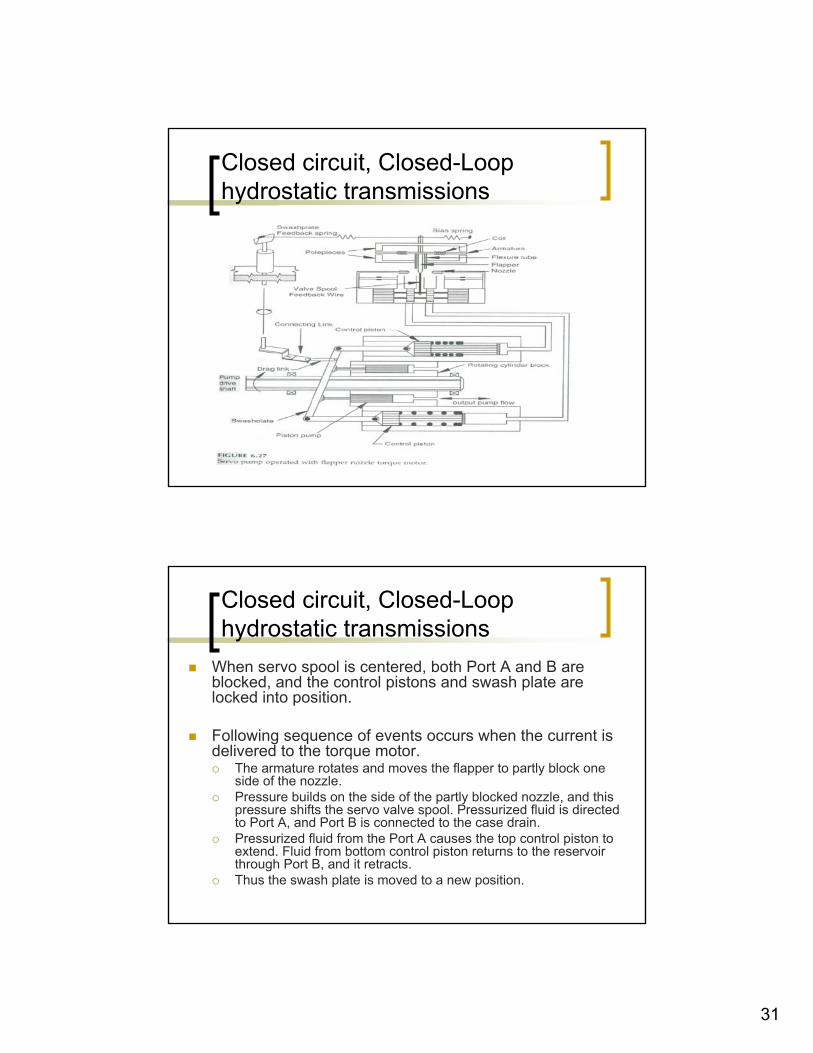
In the Servo pump shown in Fig 6.27, a torque motor is used to position the spool of the servo valve.
A torque motor rotates through several degrees of rotation, when a current is passed through the winding.
The torque motor has a flapper attached to the armature. Flapper is centered in the nozzle such that the pressure drop on both sides is equal.
This design is called a flapper nozzle torque motor.
31
Closed circuit, Closed-Loop hydrostatic transmissions
Closed circuit, Closed-Loop hydrostatic transmissions
When servo spool is centered, both Port A and B are blocked, and the control pistons and swash plate are locked into position.
Following sequence of events occurs when the current is delivered to the torque motor.
The armature rotates and moves the flapper to partly block one side of the nozzle. Pressure builds on the side of the partly blocked nozzle, and this pressure shifts the servo valve spool. Pressurized fluid is directed to Port A, and Port B is connected to the case drain.Pressurized fluid from the Port A causes the top control piston to extend. Fluid from bottom control piston returns to the reservoir through Port B, and it retracts.Thus the swash plate is moved to a new position.
32
Closed circuit, Closed-Loop hydrostatic transmissions
As swash plate moves to a new position, feedback is needed to move the servo valve spool back to the center position.
Otherwise, the spool will stay shifted, Ports A and B will stay open, and the swash plate will continue to move until it reaches it’s full displacement in one direction.
Closed circuit, Closed-Loop hydrostatic transmissions
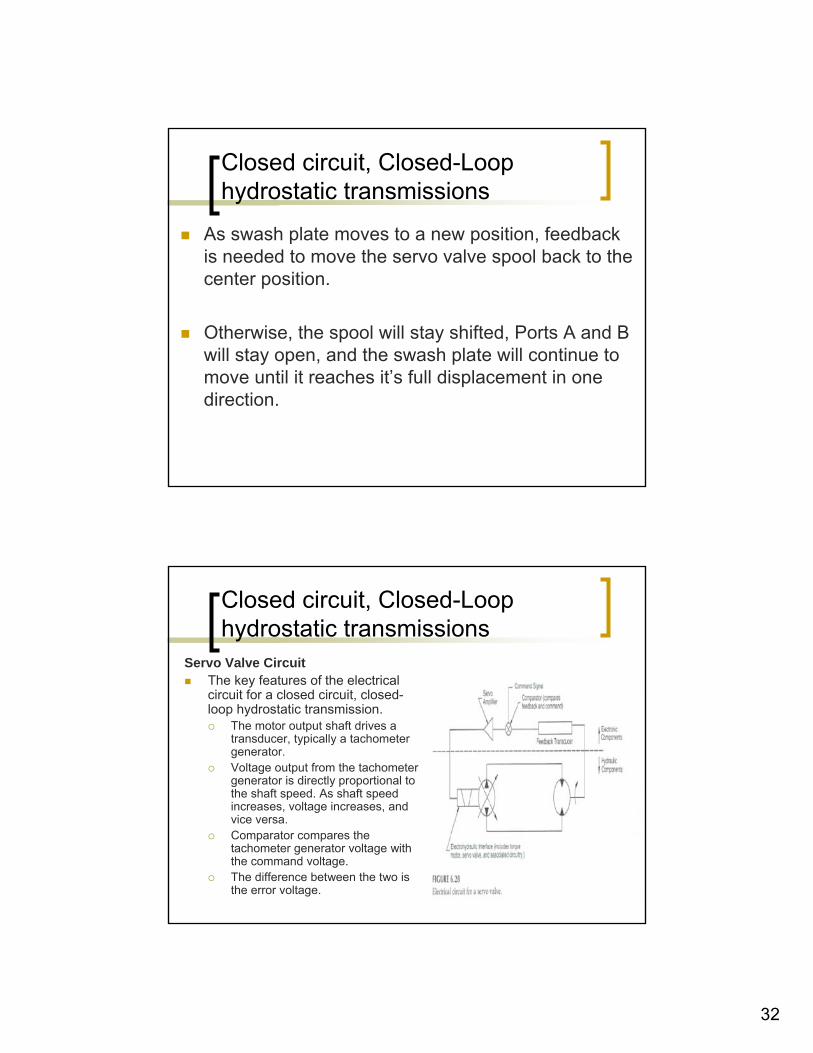
Servo Valve CircuitThe key features of the electrical circuit for a closed circuit, closed-loop hydrostatic transmission.
The motor output shaft drives a transducer, typically a tachometer generator.Voltage output from the tachometer generator is directly proportional to the shaft speed. As shaft speed increases, voltage increases, and vice versa.Comparator compares the tachometer generator voltage with the command voltage. The difference between the two is the error voltage.
33
Closed circuit, Closed-Loop hydrostatic transmissions
Response time for Closed-Loop Circuit
Response time is the time required for the motor speed to reach a new set point.
This time depends on the natural frequency of the circuit.
Closed circuit, Closed-Loop hydrostatic transmissions
Neglecting energy dissipation (damping), natural frequency is given by
f = (1/(2π)) (k / m)^1/2
Where f = natural frequency (Hz)k = elasticity (force required to produce unit deflection) (lbf / ft)m = mass (lbf .s
2/ft)
34
Closed circuit, Closed-Loop hydrostatic transmissions
If k is large, the system is said to be stiff, meaning that a little deformation occurs when a large force is applied.
A stiff system has a high natural frequency.
If m is large, meaning that a heavy load is being moved, then the natural frequency will be low.
Elasticity, k, is a function of the quantity of fluid under compression.
Closed circuit, Closed-Loop hydrostatic transmissions
If the lines are long, k will be small, thus a small force will cause a deformation .
The deformation is the change in volume of fluid in the lines. If lines are short, k will be large.
Fast response time is often important in a closed-circuit design.