hydrous ethanol steam reforming and … · using hydrous ethanol has a practical advantage for...
TRANSCRIPT

Proceedings of the ASME 2018 Internal Combustion Engine Division Fall Technical Conference ICEF2018
November 4-7, 2018, San Diego, California, USA
1
ICEF2018-9753
HYDROUS ETHANOL STEAM REFORMING AND THERMOCHEMICAL RECUPERATION TO
IMPROVE DUAL-FUEL DIESEL ENGINE EMISSIONS AND EFFICIENCY
Jeffrey T. Hwang, Seamus P. Kane, William F. Northrop* University of Minnesota
Department of Mechanical Engineering Minneapolis, MN 55455
ABSTRACT
Dual-fuel strategies can enable replacement of diesel fuel with low reactivity biofuels like hydrous ethanol. Our previous work has shown that dual-fuel strategies using port injection of hydrous ethanol can replace up to 60% of diesel fuel on an energy basis. However, they yield negligible benefits in NOx emissions, soot emissions, and brake thermal efficiency (BTE) over conventional single fuel diesel operation. Pretreatment of hydrous ethanol through steam reforming before mixing with intake air offers the potential to both increase BTE and decrease soot and NOX emissions. Steam reforming can upgrade the heating value of the secondary fuel through thermochemical recuperation (TCR) and produces inert gases to act as a diluent similar to exhaust gas recirculation. This study experimentally investigated a novel thermally integrated steam reforming reactor that uses sensible and chemical energy in the exhaust to provide the necessary heat for hydrous ethanol steam reforming. An off-highway diesel engine was operated at three speed and load settings with varying hydrous ethanol flow rates reaching fumigant energy fractions of up to 70%. The engine achieved soot reductions of close to 90% and minor NOX reductions; however, carbon monoxide and unburned hydrocarbon emissions increased. A first law energy balance using the experimental data shows that efficient TCR effectively upgraded the heating value of the secondary fuel. Overall, hydrous ethanol steam reforming using TCR can lead to 23% increase in fuel heating value at 100% conversion, a limit approached in the conducted experiments.
INTRODUCTION
Dual-fuel technologies for compression ignition engines have received considerable interest for their capacity to both supplant fossil fuel usage through renewable replacements, and to enable advanced combustion modes not possible using a single fuel. Net carbon emissions can be reduced by replacing conventional fossil fuels with a renewable secondary fuel. Hydrous ethanol is a partially renewable biofuel that contains high water fraction compared to conventionally used anhydrous bioethanol. Water removal in anhydrous ethanol refining is energy intensive. Allowing water fractions up to 25% has been
shown to decrease energy requirements for corn-ethanol refining, thus improving its renewability [1]. However, water contained in hydrous ethanol has no heating value, requires additional energy to vaporize at the point of consumption and acts as a diluent, presenting challenges for its practical use.
Our previous work [1–3] explored the use of hydrous ethanol in diesel dual-fuel combustion modes using a stock engine fuel injection calibration to determine how effective such a system could be if implemented as an aftermarket solution. When introduced through port fuel injection (PFI), hydrous ethanol achieved stable combustion with negligible impact on engine performance and up to 60% fumigant energy fraction (FEF), defined as the ratio of energy provided by the ethanol over total fuel energy. However, only minor reductions in soot and NOX were found, with excessive unburned hydrocarbons originating from the secondary fuel oxidizing NO to NO2. The work also showed that brake thermal efficiency (BTE) of the engine was not improved, contrary to some claims by aftermarket ethanol dual fuel-injection manufacturers.
An alternative approach to injecting liquid hydrous ethanol into the intake manifold of an engine to achieve dual-fuel combustion is to vaporize and pre-process the secondary fuel to alter its chemical composition, and potentially reduce in-cylinder emissions formation. Endothermically steam reforming the secondary fuel using exhaust waste heat in a thermochemical recuperation (TCR) scheme can also increase engine BTE through lower heating value (LHV) enhancement.
Although steam reforming (SR) has been used industrially for many years, ethanol and methanol SR has been recently studied as a means to achieve TCR in internal combustion engines [4–13]. The chemical formula for ideal ethanol SR is shown in Equation 1. Equation 2 gives the formula for the water gas shift (WGS) reaction which usually accompanies SR due to its favorable chemical equilibrium at reforming temperatures.
𝐶"𝐻$𝑂𝐻 +𝐻"𝑂 ↔ 2𝐶𝑂 + 4𝐻"+256.101234
5 (Eq. 1)
𝐶𝑂 + 𝐻"𝑂 ↔ 𝐶𝑂" + 𝐻"+−4101234
5 (Eq. 2)

2
Since ethanol SR can be accomplished using heterogeneous catalysts at exhaust-relevant temperatures, it is an ideal fuel for use in TCR strategies. For example, Casanovas et al. reported that ethanol steam reforming on ceria-supported noble metal catalysts with alumina and zirconia yielded high hydrogen content at high loads, while showing no carbon formation in a reactor integrated within the exhaust of a spark ignition (SI) engine [13]. In addition, in a modeling study, Chakravarthy et al. showed that TCR using ethanol in a spark ignition engine can increase the overall second law efficiency by up to 9% [6].
Using hydrous ethanol has a practical advantage for on-board reforming because it contains the necessary water for the SR reaction. The ideal reactant mixture in Equation 1 equates to a 150-proof ethanol mixture, which is 75% ethanol by volume, or a molar steam to ethanol (S/E) ratio of 1. Li et al. have shown that low water content ethanol SR (greater than 120 proof) is vital to preserve the LHV of the fuel [7]. Their work also showed that 150 proof hydrous ethanol achieved peak conversion around 675 K using an integrated reformer coupled to an SI engine. Others in the literature have investigated higher S/E ratios. Ji et al. showed that SR using a 3:1 S/E mixture (106 proof hydrous ethanol) resulted in thermal efficiency gains while HC and NOX emissions decreased in an SI engine [12]. In a literature review, Kumar et al. showed that ethanol SR can be achieved at S/E ratios up to 8 (~60 proof) with 100% conversion efficiencies using noble metal based catalysts [14].
Although some have studied using ethanol SR and TCR in spark ignition engines, few have examined reforming for diesel engines. In recent work, Chuahy et. al have shown numerically that purely endothermic reforming processes were able to achieve the highest global efficiencies compared to processes incorporating partial oxidation (POX) reforming in a dual-fuel diesel engine [15]. In addition, their work also showed that the SR cases were able to recover significantly more available exhaust energy than those using POX or a combination of SR and POX reactions.
Reforming efficiency can be calculated as the ratio of outlet to inlet fuel component energy as shown in Equation 3.
𝜂89: = <=>?@A,CDE<=>?@A,FG
(Eq. 3)
For the ideal ethanol SR reaction shown in Eq. 1, 123% reforming efficiency is possible, or a potential 23% increase in heating value. If the combustion efficiency of the engine remains constant, this excess heating value can be converted directly to work, thereby increasing the engine BTE.
In this work, a custom hydrous ethanol integrated steam reforming (ISR) reactor was studied that reclaims both chemical and sensible exhaust waste energy in a compact configuration. The engine and reactor performance are quantified for light to medium load across a range of FEF. A first-law approach to the ISR system was employed to provide a more detailed understanding energy flows within the overall system.
EXPERIMENTAL
The objective of the experimental work was to develop and characterize a novel thermally ISR reactor over a range of FEF
using 150 proof hydrous ethanol as the secondary fuel. The reactor replaced the stock engine exhaust manifold as shown in Figure 1. Exhaust gas flows through an annular diesel oxidation catalyst (DOC) reactor counter to the flow through the center SR section before entering to the turbine section of the turbocharger. The DOC both controls unburned hydrocarbon emissions from the engine and provides chemical energy to the endothermic SR reactor.
Figure 1: Schematic of hydrous ethanol ISR reactor
showing flow paths Figure 2 shows three isometric views of the reactor
assembly as constructed. The top view shows the overall manifold, the middle view depicts in reactor tube, and the bottom view highlights the oxidation catalyst in the annular region and the steam reforming catalyst the center.
Figure 2: Isometric views of the ISR reactor: a) overall
manifold, b) inner reactor tube, and c) oxidation catalyst section (annulus) and reforming catalyst section (center)
The ISR reactor consisted of five 5.5” long sections, with
5” long oxidation and reforming catalysts wash-coated on

3
brazed metal monoliths provided by Metal Substrates Inc. (Coppell, TX). The 5” OD outer annulus DOC section consisted of a 300 cpsi metal monolith, while the 2.5” OD inner SR reactor used a 600 cpsi metal monolith. The inner and outer metal monolith sections were brazed onto a common mantle which served to enhance heat transfer from the engine exhaust to the reforming section. The lower cell density of the outer annulus was used to minimize pressure drop through the DOC section. The SR monolith was coated with a Rh-containing catalyst (R44) provided by Johnson Matthey (Reading, UK), while the outer DOC section was coated with a Pt-containing catalyst also provided by Johnson Matthey. The five sections were then welded together in series and inserted into the reactor housing shown in Figure 1c with ¼ inch of alumina silica blanket on the outside of the DOC section.
A John Deere, Tier 2 emissions certified off-highway diesel engine was used in the experimental work. Specifications of the engine are given in Table 1. No modification of the engine’s stock injection calibration was made for the experiments because the goal of the research was to determine the benefits of the developed reforming system as an aftermarket dual-fuel solution.
Table 1: Engine Specifications
Manufacturer/Model John Deere 4045HF475 Engine Type 4-Stroke DI Diesel
Cylinders 4, in-line Displacement (L) 4.5
Bore x Stroke (mm) 106 x 127 Compression Ratio 17.0:1 Maximum Power
(kW/rpm) 129/2400
Aspiration Turbocharged & After Cooled
Diesel Injection System Common Rail Emissions Certification EPA Tier 2 (Off-Highway)
IVO (CAD ATDCF) 339 EVC (CAD ATDCF) 380
Figure 3 shows a schematic of the experimental setup
including the ISR reactor. To overcome the high latent heat of vaporization of water and vaporize the hydrous ethanol prior to the reactor, a custom vaporizer was constructed consisting of two, 2 kW cylindrical cartridge heaters mounted in line within an aluminum block. Hydrous ethanol was circulated along two channels on either side of the cartridge heaters, while a temperature controller and solid-state relay were used to maintain the vaporizer at a temperature of 120 °C. Electrical current data was collected using an Omega AC data logger to estimate the electrical power consumed.
To reclaim additional waste exhaust heat, a copper coil was installed inside the exhaust tube post turbocharger. Hydrous ethanol leaving the vaporizer block entered the copper coil as a superheater before being introduced into to the ISR reactor. A precision needle valve was used to control the flow rate of the hydrous ethanol, while a digital scale was used to measure the time rate of change of fuel mass using NI LabVIEW. A Red Lion (York, PA) CUB5 mechanical fuel flow meter was used to measure the directly injected diesel fuel flow and a laminar
flow element (LFE) was used to measure intake air flow rates. Reformed products were mixed with the intake air approximately 1 foot prior to the intake manifold inlet using a compact high-flow dispersion chamber.
Gaseous emissions from the exhaust pre- and post-DOC were measured using an AVL (Gratz, AUS) Fourier Transform Infrared Spectrometer (FTIR) equipped with a Flame Ionization Detector (FID) and paramagnetic oxygen analyzer. An AVL MicroSoot Sensor (MSS) was used to measure soot emissions in the exhaust stack using a dilution ratio of 20:1 with compressed air, while dry reformer products were measured using an Atmosphere Recovery Inc. (Eden Prairie, MN) Raman Laser Gas Analyzer (LGA).
Figure 3: Schematic of ISR experimental setup. Dotted
lines represent gas sampling lines In addition to engine performance and emissions data,
high-speed in-cylinder pressure data were collected at each tested condition. Kistler 6542Q128 glow plug adapters were used with Kistler Type 6065A pressure transducers for all four cylinders. A BEI H25 incremental optical encoder with 0.1 CAD resolution was mounted to the engine crank to trigger data acquisition. An in-house National Instruments LabVIEW program was used to sample 100 cycles for a total of 720,000 data points per cylinder. Apparent rate of heat release was calculated using a first law analysis as outlined in ref. [16].
Table 2: Engine and ISR reactor operating conditions
Mode Speed [RPM]
Load [N-m]
BMEP [bar]
Inner GHSV [1/hr]
Outer GHSV [1/hr]
1 1500 144 4.00 930 – 11,600
32,900 – 34,800
2 2000 144 4.00 1,300 – 11,300
46,400 – 48,000
3 2000 215 6.00 820 – 13,500
47,300 – 48,100
Three engine speed-load cases were investigated using the
ISR strategy and conventional diesel combustion (CDC), given in Table 2 along with inner and outer catalyst gas hourly space velocity (GHSV). Splash blended hydrous ethanol with 25%

4
water by volume (150 proof) was used as the secondary fuel, while non-oxygenated ultra-low sulfur diesel (ULSD) was used as the primary direct injected fuel. Fuel properties are given in Table 3, where diesel values were taken from an independent fuel study conducted by Paragon Laboratories (Livonia, MI).
Table 3: Properties of fuels used in this study
ULSD 150 Proof Ethanol
Density [kg/m3] 853 815 Heat of Vaporization [kJ/kg] 270 1015
Lower Heating Value [MJ/kg] 42.8 18.9 Cetane Number 43.2 -
At each steady state mode, the engine was first allowed to
reach steady state under CDC operating conditions. Once exhaust temperatures stabilized, vaporized hydrous ethanol was introduced into the reactor, reaching between 250 – 450 °C. Directly injected diesel fuel flow was decreased to maintain constant engine load with increasing FEF.
The ISR exit mole fractions measured on a dry basis by the LGA instrument were corrected to wet mole fractions with a carbon balance calculation using the inlet hydrous ethanol flowrate to the reactor as an input. The LGA instrument did not differentiate between different hydrocarbons (HC) in the reformer exit gas. The reformed HC distribution reported by Laosiripojana et al. was used to approximate the LGA-measured HC composition in the ISR exit as 50% methane, 20% ethylene, and 30% ethane on a molar basis [17].
Uncertainty was calculated using the standard deviations of measurements during steady state and between repeated data sets. Error bars on figures represent the root mean square value of the one standard deviation of the mean. Propagation of error was estimated using the numerical sequential perturbation approach [18]. RESULTS AND DISCUSSION Engine Performance and Emissions
The ISR reactor-equipped diesel engine was operated over a range of FEF at each testing mode shown in Table 2. Engine performance results for single fuel CDC and minimum and maximum FEF achieved at each condition are given in Table 4. All values reported were calculated on a diesel equivalent basis, and vaporizer power usage was included in all pertinent calculations. Maximum FEF was defined as when engine stability limits were reached. Any increase in flow rate beyond the stability limit resulted in unstable combustion or audible engine knock.
Combustion efficiency (CE) and air/fuel ratio (AFR), both calculated using exhaust gas compositions, decreased with increasing FEF for the low load conditions (Modes 1 & 2), but remained near CDC levels for the higher load condition (Mode 3). The decrease in CE was due to increasing UHC emissions from the engine due to incomplete combustion of the secondary fuel as is common for dual-fuel combustion modes. Brake thermal efficiency (BTE) decreased for the two, low load conditions but increased for the high load condition. This trend is coupled to the brake specific fuel consumption (BSFC),
which increased for modes 1 & 2, but decreased during mode 3. The results suggest that implementation of ISR is increasingly beneficial at higher engine loads and FEF where increased operating temperatures enables increased reforming activity to achieve conventional diesel-like CE and higher BTE. Table 4: Engine performance parameters at minimum and
maximum FEF achieved
Mode FEF [%]
BSFC [g/kW-hr]
BTE [%]
CE [%] AFR
1 Diesel - 248 33.9 99.9 35.3
ISR Min 6.12 249 33.7 99.1 37.0 ISR Max 68.3 289 29.1 97.1 31.4
2 Diesel - 252 33.4 99.9 36.2
ISR Min 5.77 262 32.1 99.3 35.4 ISR Max 48.2 265 29.6 98.2 32.6
3 Diesel - 245 34.3 99.9 26.0
ISR Min 2.69 249 33.8 99.9 27.0 ISR Max 45.8 236 35.7 99.7 25.0
Figure 4: In-cylinder pressure traces and apparent RoHR
for mode 1 (1500 RPM, 4 bar) In-cylinder pressure and calculated apparent rate of heat
release (RoHR) for Mode 1 is presented in Figure 4 for three selected FEF cases and CDC. As FEF increased, the RoHR became bimodal with a distinct premixed heat release event appearing with FEF over 50% as is common in dual fuel combustion modes with hydrogen as the secondary fuel. For example, Zhou et al. have shown a similar trend where the second heat release peak became evident once hydrogen replacement of diesel fuel reached greater than 30% [19]. Combustion phasing, as defined by CA50, advanced with increasing FEF while burn duration, defined as the duration between CA05 and CA90, decreased. These trends are primarily due to increasing premixed combustion with
5
increasing FEF. Reformate composition impacts the onset of a distinct premixed combustion mode since higher hydrogen content has a fast flame propagation speed, while methane is relatively slow [19].
At lower FEF, the RoHR trends indicate that reformate leaving the reactor burned with the diffusive diesel flame. As FEF increases, the bimodal distribution indicates that the concentration of slow burning methane is rising, however the fast burning velocity of hydrogen still reduces the burn duration. In fact, Zhou et al. have shown that hydrogen can improve methane’s combustion process while methane stabilizes hydrogen combustion to avoid engine knock [20]. Their work also showed that hydrogen should be added at higher load conditions to achieve higher combustion efficiencies, a result also seen in this work.
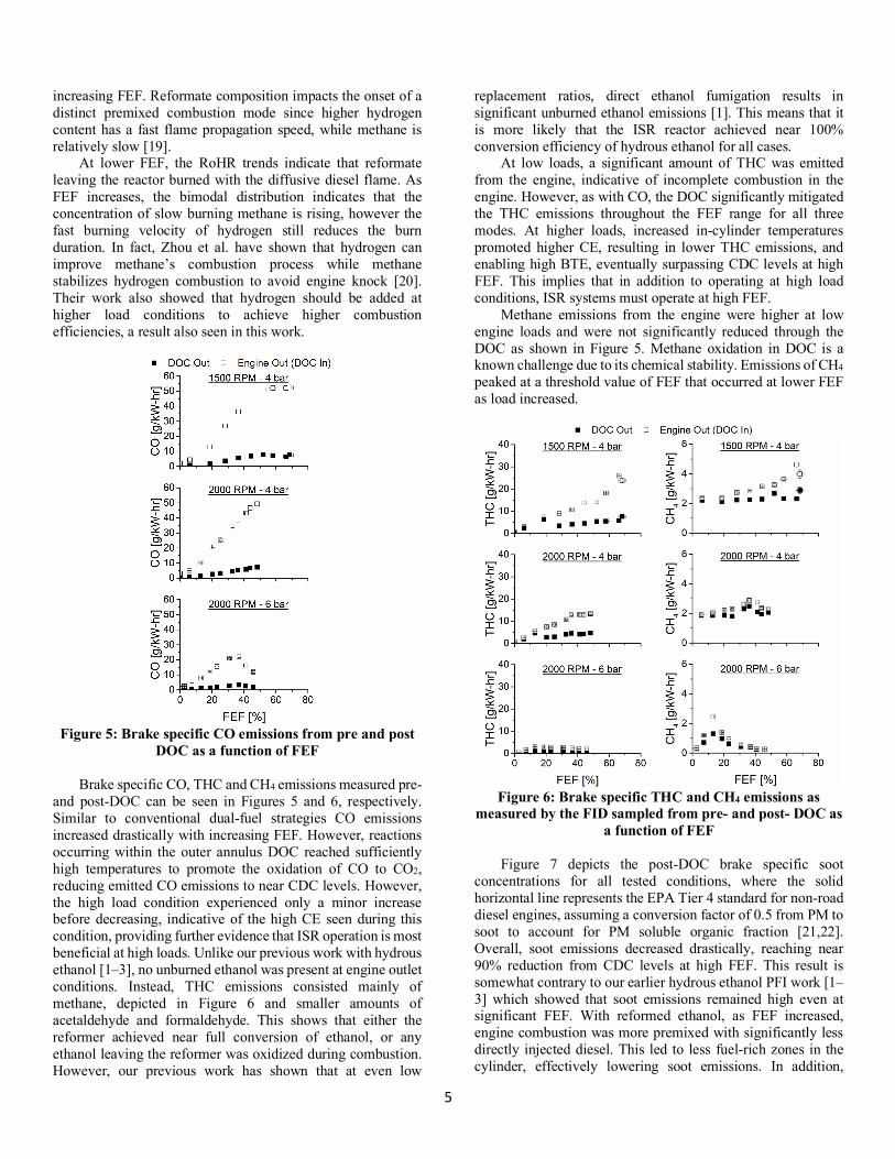
Figure 5: Brake specific CO emissions from pre and post
DOC as a function of FEF Brake specific CO, THC and CH4 emissions measured pre-
and post-DOC can be seen in Figures 5 and 6, respectively. Similar to conventional dual-fuel strategies CO emissions increased drastically with increasing FEF. However, reactions occurring within the outer annulus DOC reached sufficiently high temperatures to promote the oxidation of CO to CO2, reducing emitted CO emissions to near CDC levels. However, the high load condition experienced only a minor increase before decreasing, indicative of the high CE seen during this condition, providing further evidence that ISR operation is most beneficial at high loads. Unlike our previous work with hydrous ethanol [1–3], no unburned ethanol was present at engine outlet conditions. Instead, THC emissions consisted mainly of methane, depicted in Figure 6 and smaller amounts of acetaldehyde and formaldehyde. This shows that either the reformer achieved near full conversion of ethanol, or any ethanol leaving the reformer was oxidized during combustion. However, our previous work has shown that at even low
replacement ratios, direct ethanol fumigation results in significant unburned ethanol emissions [1]. This means that it is more likely that the ISR reactor achieved near 100% conversion efficiency of hydrous ethanol for all cases.
At low loads, a significant amount of THC was emitted from the engine, indicative of incomplete combustion in the engine. However, as with CO, the DOC significantly mitigated the THC emissions throughout the FEF range for all three modes. At higher loads, increased in-cylinder temperatures promoted higher CE, resulting in lower THC emissions, and enabling high BTE, eventually surpassing CDC levels at high FEF. This implies that in addition to operating at high load conditions, ISR systems must operate at high FEF.
Methane emissions from the engine were higher at low engine loads and were not significantly reduced through the DOC as shown in Figure 5. Methane oxidation in DOC is a known challenge due to its chemical stability. Emissions of CH4 peaked at a threshold value of FEF that occurred at lower FEF as load increased.
Figure 6: Brake specific THC and CH4 emissions as
measured by the FID sampled from pre- and post- DOC as a function of FEF
Figure 7 depicts the post-DOC brake specific soot
concentrations for all tested conditions, where the solid horizontal line represents the EPA Tier 4 standard for non-road diesel engines, assuming a conversion factor of 0.5 from PM to soot to account for PM soluble organic fraction [21,22]. Overall, soot emissions decreased drastically, reaching near 90% reduction from CDC levels at high FEF. This result is somewhat contrary to our earlier hydrous ethanol PFI work [1–3] which showed that soot emissions remained high even at significant FEF. With reformed ethanol, as FEF increased, engine combustion was more premixed with significantly less directly injected diesel. This led to less fuel-rich zones in the cylinder, effectively lowering soot emissions. In addition,

6
hydrogen is known to increase the presence of OH radicals, which have been shown to reduce soot emissions [23]. Overall, the soot trends illustrate the benefits of operating ISR systems at high FEF conditions.
Figure 7: Brake specific post DOC soot emissions as a
function of FEF. Horizontal line represents EPA Tier 4 Standard for non-road diesel engines
Brake specific NO and NO2 emissions are presented in
Figure 8 and overall NOX emissions are shown in Figure 9. While NO emissions decreased with increasing FEF, NO2 emissions increased, resulting in little change to NOX emissions, until high FEF, where a minor decrease can be seen for the low load conditions. This finding is similar to our previous work, where unburned ethanol emissions were found to facilitate the conversion of NO to NO2 [1]. However, in this work, unburned methane must be responsible for this conversion as illustrated in Figure 5. Our previous work has shown that methane has a similar propensity to convert NO to NO2. Methane reacts with OH radicals to form CH3, which oxidizes to CH3O2. This compound then reacts with NO to form NO2 and CH3O, which in turn reacts to form formaldehyde and additional HO2 radicals to further facilitate the NO to NO2 conversion.
The trends in engine outlet NO and NO2 are reversed post DOC, where the presence of UHCs (mainly CH4) and CO promote the conversion of NO2 to NO [24,25]. Katare et al. have shown that DOCs generate NO2, and also let engine out NO2 pass through when inlet temperatures are greater than 250 °C, but only after all reductants (CO and UHC) have been oxidized [24]. DOC inlet and outlet temperatures are presented in Figure 10. As expected, DOC outlet temperatures increased with FEF, as UHCs were oxidized, except for Mode 3, where CE was near 100%. Although DOC inlet temperatures were greater than 250 °C, significantly increased CO and UHC
emissions favored the reduction of NO2 to NO within the DOC, as seen in Figures 5 and 6.
Figure 8: Brake specific NO and NO2 emissions for pre
and post DOC as a function of FEF
Figure 9: Brake specific NOX emissions for pre and post
DOC as a function of FEF Due to the inverse relationship between NO and NO2 with
increasing FEF, use of ISR had minimal impact on overall NOX emissions. However, an overall decrease was seen at high FEF for Modes 1 and 2. At high FEF, NO2 reached an apparent asymptote, while NO continued to decline for engine out conditions. However, Mode 3 showed no change in NOX

7
emissions with increasing FEF, with near CDC levels of THC emissions, providing further proof that unburned hydrocarbons, mainly CH4 present during the expansion stroke, facilitated conversion of NO to NO2.
Figure 10: DOC inlet and outlet temperatures as a
function of FEF Thermally Integrated Reformer Performance
Reformer outlet H2, CO and HC, reformer efficiency (ηref), vaporizer power usage, and reformer inlet temperatures are shown as a function of FEF in Figure 11. Kumar et al. have shown that ethanol can be converted at 100% efficiency for the majority of Rh-based catalysts with inlet temperature ranges similar to those measured in this study [14]. Because no ethanol was measured in the engine exhaust, it was assumed that no ethanol was present at the exit of the ISR, implying 100% conversion efficiency. Laosiripojana et al. have shown that ethanol steam reforming over Ni-based catalysts yields mainly H2, CO, CO2, and HC consisting mostly of methane, ethylene and ethane. [17]. Therefore, the HC measured by the LGA was assumed to consist solely of those components.
At low FEF, the reactor produced mainly methane with small amounts of H2 and CO. As FEF increased, hydrogen concentration reached a steady concentration of around 40%, while methane and CO initially dropped and then increased with FEF. At the highest FEF conditions, the reformate consists predominantly of H2 and HC, with a small fraction of CO and CO2. Variations in H2 production are due to changes in catalyst conversion and selectivity.
Methane, the main HC constituent in the reformate is primarily due to two side reactions: ethanol decomposition and methanation as given in Equations 4 and 5, respectively [17,26–28]. Ethane and ethylene are formed through similar reactions.
𝐶"𝐻$𝑂𝐻 ↔ 𝐶𝐻H + 𝐶𝑂 +𝐻"+49.701234
5 (Eq. 4)
𝐶𝑂 + 3𝐻" ↔ 𝐶𝐻H + 𝐻"𝑂 +−205.901234
5 (Eq. 5)
At low FEF, reformate composition consisted of mainly gaseous HCs and small amounts of H2, resulting in low reforming efficiencies. With increasing FEF, H2 production increased, increasing ηref. Once H2 production stabilized, additional HC production began to increase ηref with FEF.
Greater than 100% reforming efficiency was calculated over almost all of the operating conditions. The reactor successfully upgraded the heating value of the 150 proof hydrous ethanol and contributed to higher BTE as reported in Table 4.
Figure 11: Reformer outlet H2, CO, and HC concentration,
reformer inlet temperature, reforming efficiency, and vaporizer power usage as a function of FEF
Initially, reformer inlet temperatures were low, but
increased as the ethanol flowrate increased. This is mainly due to increased DOC exit temperatures as shown in Figure 10. At low FEF, low flow rates caused significant heat losses between the copper coil superheater outlet and reformer inlet. Low vaporizer power also contributed to lower reformer inlet temperatures at low FEF for Mode 3, an area of potential improvement for future studies.
Electric vaporizer power reached an asymptote around 1.5 kW. The full 2 kW capability was not required. As expected, at low flow rates, minimal power is required to maintain vaporization. As the hydrous ethanol flow rate increased, electric power usage increased as expected. The vaporizer block was solely responsible for providing the latent heat of vaporization of hydrous ethanol, while the exhaust heat exchanger acted as a superheater. The heat exchanger effectiveness of the copper coil superheater in the exhaust stack was very high, reaching within 20 °C of the engine exhaust temperature. First Law Energy Balance
To further understand the achieved TCR function of the ISR reactor, a first law energy balance was performed for the whole system for CDC, and a high FEF condition at the same fuel energy input. Energy flows were calculated using calculated enthalpies and heats of reaction based on thermodynamic measurements and species mole fractions. Measurements before and after each component were incorporated into the fluid property solver, CoolProp [29] and

8
sensible transfer was calculated from the resulting difference. Chemical energy change was determined using heat of reaction and change in species concentrations measured across each component. Discrepancies between two components in thermal communication was attributed to heat loss, and total system imbalance was also accounted for by an overall loss term.
Figure 12: First law energy balance flow chart for the
CDC 2000 RPM, 6 bar operating condition
Figure 13: First law energy balance flow chart for the ISR
2000 RPM, 6 bar operating condition at 45.8% FEF
Figures 12 and 13 show the energy flow breakdown for individual components in the system for the CDC 2000-6 case and corresponding ISR condition at 45.8% FEF, respectively. The results show that the exhaust heat exchanger and DOC provided most of the sensible and chemical energy to upgrade the hydrous ethanol, while the parasitic load of the cartridge
heaters is comparatively low. However, only approximately 20% of available exhaust energy was recuperated, meaning a significant amount of sensible and chemical energy can still be recovered by optimizing the heat exchange elements.
Both CDC and ISR conditions show large heat losses to the coolant loop and atmosphere, as is typical for engines. On the other hand, reformer heat losses were minimal, accounting for only a small fraction (<1%) of the total energy entering the reactor. These losses are attributed to heat losses and conversion of hydrous ethanol to inert gases such as CO2, representing a loss in heating value. Overall, the first law energy balance shows that TCR of sensible and chemical energy present in the exhaust can effectively upgrade the heating value of hydrous ethanol using an ISR reactor using exhaust heat streams. CONCLUSIONS
In this study, a thermally integrated steam reforming reactor was experimentally investigated using 150 proof hydrous ethanol as the secondary fuel. Data were collected over a range of FEF for three engine speed/load cases reaching up to 68.3% FEF. The results showed that CO and THC emissions increased with increasing FEF, while soot emissions decreased drastically. NOX emissions decreased slightly at high FEF conditions, however unburned methane was found to facilitate conversion of NO to NO2. Counteracting these trends, the incorporated DOC reduced CO and THC emissions, while NO2 was reverted to NO. Engine thermal and combustion efficiencies suffered during low load conditions, but surpassed CDC levels at high loads, where increased operating temperatures enable CDC like CEs, while providing adequate heat to produce a higher energy content stream.
Hydrous ethanol steam reforming using TCR can lead to 23% increase in fuel heating value at 100% conversion, a limit approached in the conducted experiments. The reformer achieved TCR with greater than 100% reforming efficiency at high FEF conditions. Reformate composition results suggested that methanation and ethanol decomposition reactions occurred at high FEF where insufficient steam content promoted increased HC production. A first law analysis of the reactor system showed that 20% of the available sensible and chemical energy in the exhaust was recuperated, while the parasitic load of the cartridge heaters remained comparatively low.
Overall, our findings indicate that ISR reactors lead to higher emissions reductions, higher FEF, and additional efficiency benefits as compared to traditional liquid injection dual-fuel diesel systems with hydrous ethanol as the secondary fuel. These advantages could be realized using the stock diesel injection calibration on the engine tested in this study. Future work will examine TCR at higher engine loads, hydrocarbon speciation in the ISR products, and new reactor configurations to further refine ISR performance.
ACKNOWLEDGMENTS
This research was funded by the Minnesota Corn Research and Promotion Council under grant # 1078-EU. The authors would also like to acknowledge Andrew York and David Wails of Johnson Matthey, Plc for providing the catalysts and wash-coating used in this study.

9
NOMENCLATURE AFR Air/Fuel Ratio
ATDCF After Top Dead Center Firing BTE Brake Thermal Efficiency
BSFC Brake Specific Fuel Consumption CAD Crank Angle Degree CDC Conventional Diesel Combustion
CE Combustion Efficiency CPSI Cells Per Square Inch DOC Diesel Oxidation Catalyst EVC Exhaust Valve Close ISR Integrated Steam Reforming IVO Intake Valve Open FEF Fumigant Energy Fraction FID Flame Ionization Detector
FTIR Fourier Transform Infrared Spectrometer GHSV Gas Hourly Space Velocity
LFE Laminar Flow Element LGA Laser Gas Analyzer MSS MicroSoot Sensor NVO Negative Valve Overlap
PFI Port-Fuel Injection POX Partial Oxidation
RCCI Reactivity-Controlled Compression Ignition REGR Reformed Exhaust Gas Reformation RoHR Rate of Heat Release
S/E Steam to Ethanol Ratio SI Spark Ignition
SR Steam Reforming TCR Thermochemical Recuperation
ULSD Ultra-Low Sulfur Diesel WGS Water Gas Shift
REFERENCES [1] Hwang, J. T., Nord, A. J., and Northrop, W. F., 2017,
“Efficacy of Add-On Hydrous Ethanol Dual Fuel Systems to Reduce NO x Emissions From Diesel Engines,” ASME J. Energy Resour. Technol., 139(July).
[2] Nord, A. J., Hwang, J. T., and Northrop, W. F., 2017, “Emissions From a Diesel Engine Operating in a Dual-Fuel Mode Using Port-Fuel Injection of Heated Hydrous Ethanol,” ASME J. Energy Resour. Technol., 139(March).
[3] Hwang, J. T., and Northrop, W. F., 2014, “Gas and Particle Emissions from a Diesel Engine Operating in a Dual-Fuel Mode using High Water Content Hydrous Ethanol,” ASME Intern. Combust. Engine Div., pp. 1–9.
[4] Sall, E. D., Morgenstern, D. A., Fornango, J. P., Taylor, J. W., Chomic, N., and Wheeler, J., 2013, “Reforming of ethanol with exhaust heat at automotive scale,” Energy and Fuels, 27(9), pp. 5579–5588.
[5] Wang, F., Li, L., and Liu, Y., 2017, “Effects of flow and operation parameters on methanol steam reforming in tube reactor heated by simulated waste heat,” Int. J. Hydrogen Energy, 42(42), pp. 26270–26276.
[6] Chakravarthy, V. K., Daw, C. S., Pihl, J. A., and Conklin, J. C., 2010, “Study of the theoretical potential of thermochemical exhaust heat recuperation for internal combustion engines,” Energy and Fuels, 24(3), pp. 1529–1537.
[7] Li, G., Zhang, Z., You, F., Pan, Z., Zhang, X., Dong, J., and Gao, X., 2013, “A novel strategy for hydrous-ethanol utilization: Demonstration of a spark-ignition engine fueled with hydrogen-rich fuel from an onboard ethanol/steam reformer,” Int. J. Hydrogen Energy, 38(14), pp. 5936–5948.
[8] Cesana, O., Gutman, M., Shapiro, M., and Tartakovsky, L., 2016, “Internal combustion engine with thermochemical recuperation fed by ethanol steam reforming products - Feasibility study,” IOP Conf. Ser. Mater. Sci. Eng., 147(1).
[9] Choi, S., Bae, J., Lee, J., and Cha, J., 2017, “Exhaust gas fuel reforming for hydrogen production with CGO-based precious metal catalysts,” Chem. Eng. Sci., 163, pp. 206–214.
[10] Kuchling, T., Endisch, M., Schneider, J., Kureti, S., Hübner, W., Preis, M., and Schmidt, C., 2017, “Potential of On-Board Gasoline Upgrading for Enhancement of Engine Efficiency,” Chem. Eng. Technol., 40(9), pp. 1644–1651.
[11] Brookshear, D. W., Pihl, J. A., and Szybist, J. P., 2018, “Catalytic Steam and Partial Oxidation Reforming of Liquid Fuels for Application in Improving the Efficiency of Internal Combustion Engines,” Energy and Fuels, 32(2), pp. 2267–2281.
[12] Ji, C., Dai, X., Ju, B., Wang, S., Zhang, B., Liang, C., and Liu, X., 2012, “Improving the performance of a spark-ignited gasoline engine with the addition of syngas produced by onboard ethanol steaming reforming,” Int. J. Hydrogen Energy, 37(9), pp. 7860–7868.
[13] Casanovas, A., Divins, N. J., Rejas, A., Bosch, R., and Llorca, J., 2017, “Finding a suitable catalyst for on-board ethanol reforming using exhaust heat from an internal combustion engine,” Int. J. Hydrogen Energy, 42(19), pp. 13681–13690.
[14] Kumar, A., Prasad, R., and Sharma, Y. C., 2007, “Steam Reforming of Ethanol: Production of Renewable Hydrogen,” Chem. Pap., 11(1), pp. 1228–1239.
[15] Chuahy, F. D. F., and Kokjohn, S. L., 2017, “High efficiency dual-fuel combustion through thermochemical recovery and diesel reforming,” Appl. Energy, (195), pp. 503–522.
[16] Heywood, J. B., Internal Combustion Engine Fundamentals, McGraw-Hill Inc.
[17] Laosiripojana, N., and Assabumrungrat, S., 2007, “Catalytic steam reforming of methane, methanol, and ethanol over Ni/YSZ: The possible use of these fuels in internal reforming SOFC,” J. Power Sources, 163(2), pp. 943–951.
[18] Figliola, R., and Beasley, D., 2000, Theory and Design for Mechanical Measurements, John Wiley and Sons, New York.

10
[19] Zhou, J. H., Cheung, C. S., and Leung, C. W., 2014, “Combustion, performance, regulated and unregulated emissions of a diesel engine with hydrogen addition,” Appl. Energy, 126, pp. 1–12.
[20] Zhou, J. H., Cheung, C. S., and Leung, C. W., 2014, “Combustion, performance and emissions of a diesel engine with H2, CH4 and H2–CH4 addition,” Int. J. Hydrogen Energy, 39(9), pp. 4611–4621.
[21] Prikhodko, V. Y., Curran, S. J., Barone, T. L., Lewis, S. A., Storey, J. M., Cho, K., Wagner, R. M., and Parks, J. E., 2011, “Diesel Oxidation Catalyst Control of Hydrocarbon Aerosols From Reactivity Controlled Compression Ignition Combustion,” ASME Intern. Mech. Eng. Congr. Expo., (January 2011), pp. 273–278.
[22] 2017, “Nonroad Diesel Engine EPA Emissions Standards,” DieselNet [Online]. Available: https://www.dieselnet.com/standards/us/nonroad.php.
[23] Rahman, M. M., Stevanovic, S., Brown, R. J., and Ristovski, Z., 2013, “Influence of Different Alternative Fuels on Particle Emission from a Turbocharged Common-Rail Diesel Engine,” Procedia Eng., 56, pp. 381–386.
[24] Katare, S. R., Patterson, J. E., and Laing, P. M., 2007, “Aged DOC is a Net Consumer of NO2: Analyses of Vehicle, Engine-dynamometer and Reactor Data,” SAE Tech. Pap. Ser., (2007-01-3984).
[25] Majewski, W. A., 2018, “Diesel Oxidation Catalyst,” DieselNet [Online]. Available: https://www.dieselnet.com/tech/cat_doc.php.
[26] Aupretre, F., Descorme, C., Duprez, D., Casanave, D., and Uzio, D., 2005, “Ethanol steam reforming over MgxNi1-xAl2O3spinel oxide-supported Rh catalysts,” J. Catal., 233(2), pp. 464–477.
[27] Fatsikostas, A. N., and Verykios, X. E., 2004, “Reaction network of steam reforming of ethanol over Ni-based catalysts,” J. Catal., 225(2), pp. 439–452.
[28] Comas, J., Marino, F., Laborde, M., and Amadeo, N., 2004, “Bio-ethanol steam reforming on Ni/Al2O3catalyst,” Chem. Eng. J., 98(1–2), pp. 61–68.
[29] Bell, I. H., Wronski, J., Quoilin, S., and Lemort, V., 2014, “Pure and pseudo-pure fluid thermophysical property evaluation and the open-source thermophysical property library coolprop,” Ind. Eng. Chem. Res., 53(6), pp. 2498–2508.