hysteretic controlled buck boost fed pv inverter … s.dhanasekaran and r.s.sivakumar.,...
TRANSCRIPT

ADVANCES in NATURAL and APPLIED SCIENCES
ISSN: 1995-0772 Published BYAENSI Publication EISSN: 1998-1090 http://www.aensiweb.com/ANAS
2017 May 11(7): pages 176-183 Open Access Journal
To Cite This Article: S.Dhanasekaran and R.S.Sivakumar, Hysteretic Controlled Buck Boost Fed PV Inverter System with LCLC Filter. Advances in Natural and Applied Sciences. 11(7); Pages: 176-183
Hysteretic Controlled Buck Boost Fed PV Inverter System with LCLC Filter
1S. Dhanasekaran and 2R. S. Sivakumar
1PG Scholar, Department of EEE, Sathyabama University, Chennai, India. 2Assistant Professor, Department of EEE, Sathyabama University, Chennai, India. Received 12 February 2017; Accepted 20 April 2017; Published 25 May 2017
Address For Correspondence: S.Dhanasekaran, PG Scholar, Department of EEE, Sathyabama University, Chennai, India. E-mail: [email protected]
Copyright © 2017 by authors and American-Eurasian Network for Scientific Information (AENSI Publication). This work is licensed under the Creative Commons Attribution International License (CC BY). http://creativecommons.org/licenses/by/4.0/
ABSTRACT This paper deals with comparison of responses of Buck Boost Fed PV and Inverter System (BBPVIS) with PI and hysteretic controllers. The output of PV array is stepped up using Buck Boost converter and its output is converted to fifty hertz AC using an inverter. LCLC filter is proposed at the output of the inverter to reduce the harmonics. Closed loop PI & HC based BBPVIS system are modeled, simulated and the corresponding results are presented. The studies indicate that the response with HC is superior to PI controlled BBPVI system. KEYWORDS: Hysteritic Controller, Buck Boost fed FV, Inverter System, PI Controller, LCLC Filter
INTRODUCTION
Due to the global energy challenge, grid-tied inverters for the renewable energy sources are becoming
widely used today’s [1]–[3]. They can be divided into voltage-source inverters (VSI) and current-source
inverters (CSI), where the VSI is the dominant converter. One of the reasons is that the VSI does not need a
large inductor as the energy storage element, while the CSI should adopt a larger inductor in order to keep the dc
current constant for a proper modulation. The research related to CSI mainly focus on the control [4]–[7]. So far,
how to decrease the total dc-link inductance for CSI is a challenge, especially in the low voltage and three-phase
application area. Since the VSI is a step-down inverter and the CSI is a kind of step-up inverter, the Z-source
inverters (ZSI) was proposed in [8] in order to fully utilize the basic character of VSI and CSI and the minimum
semiconductors were used with the combined characters of the step-down and the step-up converters. However,
compared to the CSI or the VSI, the ZSI has two extra inductors in the power loop, which may sacrifice the
efficiency [9], [10]. The control difficulty is also a demerit in the Z-source impedance.
In the renewable power generation system, the input dc voltage of the converter may vary greatly. For
example, the output dc voltage of a solar panel will change a lot under different temperature conditions. To
transfer this kind of dc energy into the grid, a two- or three-stage inverter may be required as the power
interface, especially for the VSI-based system. If all power stages work at high frequency, the efficiency of the
inverter will be inevitable affected. In order to decrease the switching frequency, many interesting inverters have
been proposed [11]–[13] and the basic idea is to ensure that only one of the power stages of the system works at
high frequency.

177 S.Dhanasekaran and R.S.Sivakumar., 2017/Advances in Natural and Applied Sciences. 11(7) May 2017, Pages: 176-183
Nevertheless, the main output filter of these inverters should be designed to satisfy the harmonic
requirements [14] in the “buck” mode, especially when the dc input voltage is higher than the amplitude of the
grid voltage. Thus, when they work in the “boost” mode, an over filtering may take place due to that the output
filter is a CL–CL filter. Since the excessive inductance is in the power loop, extra conduction losses will be
present and the grid current is not easy to control as well. A consensus has been reached that the power
electronics will take a main role in the future energy area [15]. But which favorite type of grid-tied inverters for
the future is still discussed. Dependent on the efficiency evaluation, the smaller inductance in the power loop
will cause a higher efficiency, due to the fact that the power loss caused by power device has become smaller
and smaller. Thus, it may be a good way to achieve high efficiency through decreasing the total inductance in
the power loop. It should be pointed out that aiming to minimize the inductance of output filter of VSI, a
recently new type of power filter named as the LLCL-filter was proposed and analyzed for the grid-tied VSI
[16]–[18].
Theoretically, compared with an LCL-filter, an LLCL-filter can save the total inductance. Due to the reason
of familiarity, the conventional LCL-filter is still used as the output filter benchmark for the comparison between
several classical inverters. In this paper, typical full-bridge single-phase grid-tied inverters with the different
power sources are introduced. Next, a new type of “buck in buck, boost in boost” grid-tied inverter is proposed
and the operating principle is illustrated through a half-bridge inverter with the equivalent circuits in the
different working stages. Then, the modeling is carried out with a small signal model method. Based on this, an
indirect current control method is introduced, when the inverter is working in the “boost” stage. Finally,
simulations and experiments are given to verify the theoretical analysis and the principle of operation.
Fig. 1: Single-phase grid-tied VSI.
Fig. 2: Single-phase grid-tied CSI.

178 S.Dhanasekaran and R.S.Sivakumar., 2017/Advances in Natural and Applied Sciences. 11(7) May 2017, Pages: 176-183
Fig. 3: Single-phase grid-tied ZSI
Typical Full-Bridge Single-Phase Grid-Tied Inverter With The Different Power Source:
A. Single-Stage Inverters:
1) Inverters With the Single Function of Step-Down or Step- Up: Figs. 1 and 2 show the typical VSI with
LCL-filter and the typical CSI with CL-filter, respectively. The VSI is bucktype (step-down) inverter, which
means its dc voltage should be higher than the amplitude of the grid voltage. The CSI is a boost-type (step-up)
inverter, which means that its dc voltage should be lower than the amplitude of the grid voltage [19]. Generally,
the output dc voltage of the renewable power source (for example, a PV panel) may vary in a large range, then
the VSIs or the CSIs have their own limitations as a renewable power conditioner connected to the grid directly,
and after an additional dc/dc converter is used.
2) Inverters With the Function of Both Step-Down and Step-Up:
a) ZSI:
Combined with the voltage characters of the VSI and the CSI, a Z-source type inverter was proposed [8]. In
theory, ZSI (as shown in Fig. 3) can work in the step-down and the step-up states as required and its reliability
can be improved a
Fig. 4: Single-phase grid-tied natural soft-switching inverter
lot, owing to its immunity to the electromagnetic interference. However, due to the two additional inductors
in the power loop, the conduction power loss is high and over filtering may also take place, especially when the
input dc voltage is high. It is basically a boost–buck type converter and it is difficult to realize the overall
parameter optimization, when the input dc voltage varies in a large range. The efficiency of the ZSI seems not as
high as that of the other conventional two-stage inverters [9], [10].
b) Natural Soft-Switching Inverter (NSSI):
For a VSI, the reverse recovery power loss and the power losses caused by the tail current of insulated-gate
bipolar transistor (IGBT) limit the switching frequency of the VSI [20.For the CSI, the high conduction power

179 S.Dhanasekaran and R.S.Sivakumar., 2017/Advances in Natural and Applied Sciences. 11(7) May 2017, Pages: 176-183
losses of the devices and the high power losses caused by the dc-link inductor are the main drawbacks related to
the efficiency. Nevertheless, the CSI has no reverse recovery power losses.
Using the merit of VSI and CSI and avoiding the demerit of them, a high efficiency inverter was proposed
[21] as shown in Fig. 4 (For a single-phase application), named as the NSSI. When the additional switch of S5 is
ON, the inverter works as a pure VSI with an LC-type dc input filter and an LCL type of ac output filter. While
S5 is OFF, it works like a CSI with a clamped voltage and an LCL filter. Thus, this inverter can fit for a wide
variation of input dc voltage, especially for the permanent magnet synchronous wind generator with a front-end
diode rectifier. An improved NSSI was proposed to increase the efficiency when it is used for the three-phase
photovoltaic inverter application [22], whereas an additional boost dc/dc circuit had been inserted. Note that the
NSSI may have a higher efficiency than the traditional two-stage VSI, since more switches can work in the soft-
switching or quasi-soft-switching state. More efficiency analysis about this inverter is introduced in [23].
However, the inductance in the power loop still seems large. The above literature does not deal with comparison
of PI & HC based BBPVI system. This work proposes HC for BBPVI system.
III Simulation Results:
Closed loop system with PI controller is shown in Fig 5.1. The output voltage of solar system is shown in
Fig 5.2 and its value is increases from 10 to 15 V. The output voltage of Buck Boost converter is shown in Fig
5.3 and its value is 250 V. The output voltage of inverter is shown in Fig 5.4. The output current of inverter is
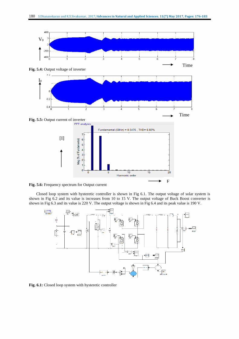
shown in Fig 5.5. The spectrum for output current is shown in Fig 5.6 and THD is 6.8 %.
Fig. 5.1: Closed loop system with PI controller
Fig. 5.2: Output voltage of solar
Fig. 5.3: Output voltage of buck boost converter
VPV
V
Time
V0
Time
180 S.Dhanasekaran and R.S.Sivakumar., 2017/Advances in Natural and Applied Sciences. 11(7) May 2017, Pages: 176-183
Fig. 5.4: Output voltage of inverter
Fig. 5.5: Output current of inverter
Fig. 5.6: Frequency spectrum for Output current
Closed loop system with hysteretic controller is shown in Fig 6.1. The output voltage of solar system is
shown in Fig 6.2 and its value is increases from 10 to 15 V. The output voltage of Buck Boost converter is
shown in Fig 6.3 and its value is 220 V. The output voltage is shown in Fig 6.4 and its peak value is 190 V.
Fig. 6.1: Closed loop system with hysteretic controller
V0
Time
I0
Time
F
[I]

181 S.Dhanasekaran and R.S.Sivakumar., 2017/Advances in Natural and Applied Sciences. 11(7) May 2017, Pages: 176-183
Fig. 6.2: Output voltage of solar system
Fig. 6.3: Output voltage of buck boost converter
Fig. 6.4: Output voltage of Inverter
The output current is shown in Fig 6.5 and its peak value is 0.2 A. The frequency spectrum for output
current is shown in Fig 6.6. The comparison of time domain parameters is shown in Table-1. The comparison of
current harmonics is shown in Table-2. The time response with HC is better than that of PI corbelled system.
The THD with HC is less than that of PI controlled BBPVI system.
Fig. 6.5: Output current of Inverter
Fig. 6.5: Frequency spectrum for Output current
Time
VPV
V0
Time
Voi
Time
iI
Time
[I]
F

182 S.Dhanasekaran and R.S.Sivakumar., 2017/Advances in Natural and Applied Sciences. 11(7) May 2017, Pages: 176-183
Table 1: Comparison of Time Domain Parameters
Controller Tr Ts Tp Ess
PI controller 2.2 4 2.3 5.2
Hysteresis 2.1 3 2.1 4.6
Table 2: Comparison of Current Harmonics
Controller THD
PI controller 6.83%
hysteresis controller 4.70%
Conclusion:
PI & hysteretic Controlled BBPVI systems are successfully designed and simulated using Matlab and the
results are presented. The settling time with HC is 3 sces and steady state error in voltage is 4.6 V. The THD in
the output current with HC is 4.7 %. Therefore the response with HC is better than that of PI controlled BBPVI
system. The advantages of proposed system are high gain, low THD and reduced steady state error. The
disadvantage of this system is that it is suitable for low power levels.
The present work deals with comparison of responses with PI & HC. The comparison of responses with PI
& FLC based BBPVI system will be done at a later date.
REFERENCES
1. Kolar, J.W., T. Friedli, J. Rodriguez and P.W. Wheeler, 2011. Review of three phase PWM ac–ac converter
topologies. IEEE Trans. Ind. Electronics. 58(11): 4988-5006.
2. Meneses, D., F. Blaabjerg, O´. Garc´ıa and J.A. Cobos, 2013. Review and comparison of step-up
transformerless topologies for photovoltaic ac-module application. IEEE Trans. Power Electronics. 28:
2649-2663.
3. Blaabjerg, F., M. Liserre and K. Ma, 2012. Power electronics converters for wind turbine systems. IEEE
Trans. Ind. Appl., 48: 708-719.
4. Lee, H.J., S. Jung and S.K. Sul2 013. Current controller design for current source inverter-fed ac machine
drive system. IEEE Trans. Power Electronics. 28: 1366-1381.
5. Zhu, N., D. Xu, B. Wu, N.R. Zargari, M. Kazeraniand F. Liu, 2013. Common mode voltage reduction
methods for current-source converters in medium voltage drives. IEEE Trans. Power Electronics. 28: 995-
1006.
6. Wang, Z., B. Wu, D. Xu and N. Zargari, 2011. Hybrid PWM for high-power current-source-inverter-fed
drives with low switching frequency. IEEE Trans. Power Electronics. 26: 1754-1764.
7. Li, R.T.H., H.S.H. Chung and T.K.M. Chan, 2007. An active modulation technique for single-phase grid-
connected CSI, IEEE Trans. Power Electronics, 22: 1373-1382.
8. Peng, F.Z., 2003. Z-source inverter, IEEE Trans. Industrial Applications, 39: 504-510.
9. Burkart, R., J.W. Kolar and G. Griepentrog, 2012. Comprehensive comparative evaluation of single- and
multi-stage three-phase power converters for photovoltaic applications, presented at the IEEE 34th
International Telecommunications Energy Conference, Scottsdale, AZ, USA.
10. Li, J., J. Liu and Z. Liu, 2009. Comparison of Z-source inverter and traditional two-stage boost-buck
inverter in grid-tied renewable energy generation, in Proc. IEEE 6th Int. Power Electronics Motion Control
Conf., Wuhan, China, 17–20: 1493-1497.
11. Ogura, K., T. Nishida, E. Hiraki,M. Nakaoka and S. Nagai, 2004. Time-sharing boost chopper cascaded
dualmode single-phase sinewave inverter for solar photovoltaic power generation system in Proc. IEEE
35th Annu. Power Electronics. Spec. Conf., 20-25: 4763-4767.
12. Wu, W. and T. Tang, 2007. Dual mode time-sharing cascaded sinusoidal inverter. IEEE Trans. Energy
Converters, 22: 795-797.
13. Zhao, Z., M. Xu, Q. Chen, J. Lai and Y. Cho, 2012. Derivation, analysis, and implementation of a boost–
buck converter-based high-efficiency PV inverter, IEEE Trans. Power Electronics, 27: 1304-1313.
14. IEEE Application Guide for IEEE Std.,2008. IEEE Standard for Interconnecting Distributed Resources
With Electric Power Systems, IEEE 2.
15. Bose., B.K., 2013. Global energy scenario and impact of power electronics in 21st century. IEEE Trans.
Ind. Electronics. 60: 2638-2651.
16. Wu, W., Y. He, and F. Blaabjerg, 2012. An LLCL-power filter for single-phase grid-tied inverter. IEEE
Trans. Power Electronics. 27: 782-789.
17. Wu, W., Y. He, T. Tang and F. Blaabjerg, 2013. A new design method for the passive damped LCL- and
LLCL-filter based single-phase grid-tied inverter. IEEE Trans. Ind. Electronics. 60: 4339-4350.
a. Wu, W., Y. Sun, M. Huang, X. Wang, H. Wang, F. Blaabjerg, M. Liserre and H.S.H. Chung, 2014. robust passive damping method for LLCL filter based grid-tied inverters to minimize the effect of grid harmonic
voltages . IEEE Trans. Power Electronics. 29: 3279-3289.

183 S.Dhanasekaran and R.S.Sivakumar., 2017/Advances in Natural and Applied Sciences. 11(7) May 2017, Pages: 176-183
18. Caceres, R.O. and I. Barbi, 1999. A boost dc-ac converter: Analysis, design, and experimentation. IEEE
Trans. Power Electronics. 14: 134-141.
19. Wintrich, A., U. Nicolai, W. Tursky and T. Reimann, 2011. Application Manual Power Semiconductors.
Nuremberg, Germany: Semikron Int., pp: 275-279.
20. Wu, W., B. Gu, Z.M. Qian and F.Z. Peng, 2005. A natural soft-switch power converter with adjustable dc-
link voltage. in Proc. Chin. Soc. Elect. Eng., 25: 62-66.
21. Wu, W., P. Geng, J. Chen, Y. Ye and T. Tang, 2010. A novel three-phase quasisoft- switching dc/ac
inverter. in Proc. IEEE Int. Symp. Power Electronics. Distrib. Gener. Syst., Hefei, China, 16-18: 477-480.
22. Geng, P., W. Wu and F. Blaabjerg, 2013. Efficiency analysis on a two-level three-phase quasi-soft-
switching inverter. in Proc. Appl. Power Electronics, Conf., Long Beach, CA, USA, 17-21: 1206-1212.
23. Ahmed, N.A., H.W. Lee and M. Nakaoka, 2007. Dual-Mode time-sharing sinewave-modulation soft
switching boost full-bridge one-stage power conditioner without electrolytic capacitor dc link. IEEE Trans.
Ind. Appl., 43: 805-813.
24. Xue, M., Y. Zhang, Y. Kang, Y. Yi, S. Li and F. Liu, 2012. Full feedforward of grid voltage for discrete
state feedback controlled grid-connected inverter with LCL filter. IEEE Trans. Power Electronics, 27:
4234-4247.
25. Mohamed, Y.A.-R.I., M.A. Rahman and R. Seethapathy2012. Robust linevoltage sensorless control and
synchronization of LCL-filtered distributed generation inverters for high power quality grid connection.
IEEE Trans. Power Electronics, 27: 87-98.
26. He, J. and Y.W. Li., 2012. Generalized closed-loop control schemes with embedded virtual impedances for
voltage source converters with LC or LCL filters. IEEE Trans. Power Electronics, 27: 1850-1861.
27. Wu, W., H. Geng, P. Geng, Y. Ye and M. Chen, 2010. Anovel control method for dual mode time-sharing
grid-connected inverter. in Proc. IEEE Energy Converters. Congr. Expo., Atlanta, GA, USA, 12-16: 53-57.
28. Mulethaler, J., M. Schweizer, R. Blattmann, J.W. Kolar and A. Ecklebe, 2013. Optimal design of LCL
harmonic filters for three-phase PFC rectifiers. IEEE Trans. Power Electronics, 28: 3114-3125.
29. He, N., D. Xu, Y. Zhu, J. Zhang, G. Shen, Y. Zhang, J. Ma and C. Liu, 2013. Weighted average current
control in a three-phase grid inverter with an LCL filter. IEEE Trans. Power Electronics, 28: 2785-2797.
30. Bao, X., F. Zhuo, Y. Tian and P. Tan, 2013. Simplified feedback linearization control of three-phase
photovoltaic inverter with an LCL filter. IEEE Trans. Power Electronics, 28: 2739-2752.
31. Hao, X., X. Yang, T. Liu, L. Huang and W. Chen, 2013. A sliding-mode controller with multi resonant
sliding surface for single-phase grid-connected VSI with an LCL filter. IEEE Trans. Power Electronics,
28: 2259-2268.
32. lvaperumal, S., C.C.A. Rajan and S. Muralidharan, 2013. Stability and performance investigation of a
fuzzy-controlled LCL resonant converter in an RTOS environment.IEEE Trans. Power Electronics, 28:
1817-1832.
33. Wu, W., Y. Sun, Z. Lin,Y. He, M. Huang, F. Blaabjerg and H.S.-H. Chung, 2014. A modified LLCL filter
with the reduced conducted EMI noise. IEEE Trans. Power Electronics, 29: 3393-3402.