i-500 - es. · pdf fileseries 786 ta stas soldered-end circuit balancing valve instructions...
TRANSCRIPT

I-500_1
I-500FIELD INSTALLATION HANDBOOK
• O-RING INFORMATION
• PIPE PREPARATION
• PRODUCT INSTALLATION
I-500FIELD INSTALLATION HANDBOOK
WARNING
• Readandunderstandallinstructionsbeforeattemptingtoinstall,remove,adjust,ormaintainanyVictaulicproducts.
• Depressurizeanddrainpipingsystemsbeforeattemptingtoinstall,remove,adjust,ormaintainanyVictaulicproducts.
• Wearsafetyglasses,hardhat,footprotection,andhearingprotection.
Failure to follow instructions and warnings could cause system failure, resulting in serious personal injury and/or property damage.
If you need additional copies of any instructions, or if you have questions about the safe and proper installation or operation of
Victaulic products, contact Victaulic.
For the most up-to-date information on Victaulic products, visit: www.victaulic.com
DISCONTIN
UED PRODUCT

I-500_iTABLE OF CONTENTS REv_E
Table of ContentsINDEX.............................................................................................. ii
GENERAL INFORMATION
HAZARDIDENTIFICATION................................................................2INTRODUCTION...............................................................................3IMPORTANTINFORMATION.............................................................4
Type304StainlessSteel......................................................... 4
Type316StainlessSteel.......................................................... 4
CarbonSteel........................................................................... 5
IMPORTANTINFORMATION–PREVENTIONOFSTAINLESSSTEELCONTAMINATION................................................6
HandlingandStorage.............................................................. 6
Shipping.................................................................................. 6
PIPESPECIFICATIONS......................................................................7MINIMUMPIPE-NIPPLELENGTHREQUIREMENTS..........................7PIPINGSUPPORT.............................................................................8PIPEPREPARATION.........................................................................9OPERATORSAFETYREQUIREMENTSFORPRESSFITTOOLS........10PRESSFITTOOLRATINGS..............................................................11
SPACEREQUIREMENTSFORTHEPRESSINGOPERATION–PFT505ELECTRICPRESSFITTOOL...............................................12
SPACEREQUIREMENTSFORTHEPRESSINGOPERATION–PFT509BATTERY-POWEREDPRESSFITTOOL...............................13
O-RINGSELECTION........................................................................14
INSTALLATION INSTRUCTIONS FOR PRESSFIT SYSTEM PRODUCTS
PRODUCTINSTALLATION..............................................................16INSTALLATIONINSPECTION..........................................................21
PRODUCT DATA ..............................................22
DISCONTIN
UED PRODUCT

I-500_ii
DISCONTIN
UED PRODUCT

I-500_iiiINDEX REv_E
IndexThefollowingtableprovidesalistingofproductsandinstallationinformation.Ifyouneedadditionalcopiesofanyinstallationinformation,contactVictaulicat1-800-PICKVIC.NOTE:Iftwosourcesofinstructionsarereferencedinthisindex,Victaulicrecommendstheuseofbothtoensureproperproductinstallation.
Product Where to Find Instructions
Depend-O-LokCouplings InstructionsShippedwithCoupling
FireLockAutomaticSprinklerProducts I-40
FireLockCPVCSprinklerSystemProducts I-800
FireLockFireProtectionValvesandAccessories
ManualShippedwithValveorAccessory
PermaLynxPermanentPush-to-ConnectSystemProducts
I-PermaLynxandI-600
PipePreparationTools ManualShippedwithPipePreparationTool
PressfitProducts I-500
Series317AWWACheckValve I-317
Series365AWWAVic-PlugValve(3–12-inch/88.9–323.9-mmSizes)
I-365/366/377.3-12
Series365AWWAVic-PlugValve(14–18-inch/355.6–457.0-mmSizes)
I-365.14-18
Series366AWWAVic-PlugValve I-365/366/377.3-12
Series377Vic-PlugBalancingValve I-365/366/377.3-12
Series608CopperConnectionButterflyValve
I-600
Series700ButterflyValve I-100
Series705WFireLockButterflyValve I-705W
Series706ButterflyValve I-100
Series707SupervisedClosedButterflyValve
I-707
Series709ButterflyValve I-100
Series712/712SSwingerCheckValve I-100
Series713SwingerCheckValve I-100
Series716Vic-CheckValve I-100
Series717FireLockCheckValve I-100
Series717RFireLockRiserCheckValve I-100
Series723DiverterBallValve I-100
Series726BallValve I-100
Series728FireLockBallValve I-728
Series730Vic-Strainer®TeeType I-730/732/AGS
SeriesW730AGSVic-StrainerTeeType I-730/732/AGS
DISCONTIN
UED PRODUCT

I-500_iv INDEX REv_E
Product Where to Find Instructions
Series731-ISuctionDiffuser I-731I/W731I
SeriesW731-IAGSSuctionDiffuser I-731I/W731I
Series732Vic-StrainerWyeType I-730/732/AGS
SeriesW732AGSVic-StrainerWyeType I-730/732/AGS
Series733VenturiIndicator I-100
Series747MFireLockZoneControlRiserModuleAssembly
I-747M
Series763ButterflyValve I-100
Series779VenturiCheckValve I-100
Series782/783TABypass InstructionsShippedwithValve
Series785TATBVSSweated-EndMiniCircuitBalancingValve
InstructionsShippedwithValve
Series786TASTASSoldered-EndCircuitBalancingValve
InstructionsShippedwithValve
Series787TASTADNPTFemaleThreadedCircuitBalancingValve
InstructionsShippedwithValve
Series788TASTAFFlanged-EndCircuitBalancingValve
InstructionsShippedwithValve
Series789TASTAGGrooved-EndCircuitBalancingValve
InstructionsShippedwithValve
Vic-300ButterflyValve I-100
Style005FireLockRigidCoupling I-100
Style009/009VFireLockEZ™RigidCoupling
I-100
Style07Zero-FlexRigidCoupling(1–12-inch/33.7–323.9-mmSizes)
I-100
Style07Zero-FlexRigidCoupling(14–24-inch/355.6–610.0-mmSizes)
I-100andIT-07
StyleW07AGSRigidCoupling I-100andI-W07/W77
Style22CouplingforVic-RingAdaptersandShouldered-EndPipe
I-6000
Style31CouplingforAWWADuctileIron I-300
Style31CouplingforVic-RingAdaptersandShouldered-EndPipe
I-6000
Style41CouplingforVic-RingAdaptersandShouldered-EndPipe
I-6000
Style44CouplingforVic-RingAdaptersandShouldered-EndPipe
I-6000
Style72OutletCoupling I-100
Style74ODFlexibleCoupling I-100
Style75FlexibleCoupling I-100
Style77FlexibleCoupling I-100
StyleW77AGSFlexibleCoupling I-100andI-W07/W77
DISCONTIN
UED PRODUCT

I-500_vINDEX REv_E
Product Where to Find Instructions
Style78Snap-JointCoupling I-100
Style89RigidCouplingforStainlessSteel I-100andIT-89
Style99Roust-A-BoutCouplingforPlain-EndSteel
I-100andIT-99
Style107QuickVic®RigidCouplingforSteelPipe
I-107andI-100
Style150MoverExpansionJoint Submittal09.06
Style155ExpansionJoint Submittal09.06
Style307CouplingforGroovedIPSSteeltoGroovedAWWADuctileIron
I-300
Style341Vic-FlangeAdapterforAWWADuctileIron
I-300
Style441Vic-FlangeforStainlessSteel I-100andI-441
Style475Lightweight,FlexibleStainlessSteelCoupling
I-100
Style489RigidCouplingforStainlessSteel(11 /2–4-inch/48.3–114.3-mmSizes)
I-100andIT-489.2-4
Style 489 Rigid Coupling for StainlessSteel(6–12-inchand139.7–318.5-mmMetricandJISSizes)
I-100andIT-489
Style606RigidCouplingforCopperTubing
I-600
Style607QuickVic®RigidCouplingforCopperTubing
I-607andI-600
Style622Mechanical-T®BoltedBranchOutletforCopperTubing
I-622andI-600
Style641Vic-FlangeAdapterforCopperTubing
I-600
Style707-IJTransitionCouplingforNPStoJIS
I-100
Style720TestMasterIIAlarmTestModule
I-720
Style720TestMasterIIAlarmTestModulewithPressureReliefOption
I-720PR
Style730Vic-StrainerTee-Type I-730/732
Style731-GSuctionDiffuser I-731G
Style732Wye-TypeVic-Strainer I-730/732
Style733VenturiFlowMeteringSensor I-100
Style734/734SOrifice/IndicatorFlowMeteringSystem
I-100
Style735FirePumpTestMeter I-100
Style738TAPortableDifferentialMeter InstructionsShippedwithMeter
Style739PortableMasterMeter InstructionsShippedwithMeter
DISCONTIN
UED PRODUCT

I-500_vi INDEX REv_E
Product Where to Find Instructions
Style740TACBIMeter InstructionsShippedwithMeter
Style741IPSandMetricVic-FlangeAdapter
I-100
StyleW741AGSVic-FlangeAdapter I-100andIT-W741
Style743Vic-FlangeAdapter I-100
Style744FireLockFlangeAdapter I-100
Style750ReducingCoupling I-100
Style770Large-diameterCoupling I-100andIT-770
Style791Vic-BoltlessCoupling I-100
Style808Duo-LockCoupling I-808
Style920and920NMechanical-TOutlets
I-100andI-920N
Style922FireLockOutlet-T I-100andI-922
Style923Vic-LetStraplessOutlet I-100andI-923
Style924Vic-O-WellStraplessThermometerOutlet
I-100
Style926Mechanical-TSpigotAssembly I-100andI-926
Style931Vic-TapIIMechanical-T VT-II
Style994Vic-FlangeAdapterforHDPE I-900andIT-994
Style995CouplingforPlain-EndIPSandMetricHDPE
I-900andIT-995
Style997TransitionCouplingforHDPEtoSteel
I-900andIT-997
Style2970AquamineCouplingforPlain-endIPSPVC
IT-2970
Style2971AquamineTransitionCouplingforPlain-EndIPSPVCtoPlain-EndHDPE
IT-2971
Style2972AquamineTransitionCouplingforPlain-EndIPSPVCtoGroovedIPSSteel
IT-2972
StyleHP-70RigidCoupling(2–12-inch/60.3–323.9-mmSizes)
I-100
StyleHP-70RigidCoupling(14–16-inch/355.6–406.4-mmSizes)
I-100andIT-70
StyleHP-70ESRigidCouplingwithEndSealGasket(2–12-inch/60.3–323.9-mmSizes)
I-100
DISCONTIN
UED PRODUCT

I-500_1
General Information
DISCONTIN
UED PRODUCT

I-500_2 GENERAL INFORMATION REv_E
HAZARD IDENTIFICATIONDefinitions for identifying the various hazard levels are provided below.
Thissafetyalertsymbolindicatesimportantsafetymessages.Whenyouseethissymbol,bealerttothepossibilityofpersonalinjury.Carefullyreadandfullyunderstandthemessagethatfollows.
DANGER
The use of the word “DANGER” • identifies an immediate hazard with a likelihood of death or serious personal injury if instructions, including recommended precautions, are not followed.
WARNINGThe use of the word “WARNING” • identifies the presence of hazards or unsafe practices that could result in death or serious personal injury if instructions, including recommended precautions, are not followed.
CAUTIONThe use of the word “CAUTION” • identifies possible hazards or unsafe practices that could result in personal injury and product or property damage if instructions, including recommended precautions, are not followed.
NOTICE
The use of the word “NOTICE” • identifies special instructions that are important but not related to hazards.
DISCONTIN
UED PRODUCT

I-500_3GENERAL INFORMATION REv_E
INTRODUCTIONThisfieldinstallationhandbookisabasicfieldreferenceguideforVictaulicPressfitProducts.Thishandbookprovideseasyreferencetoproperinstallationinformation.Inadditiontothishandbook,Victaulicoffersthefollowinghandbooksforotherproducts/materials:• I-100–InstallationInstructionsforIPSandMetricCarbonSteel,StainlessSteel,
andAluminumProducts
• I-300–InstallationInstructionsforAWWAProducts
• I-600–InstallationInstructionsforCopperConnectionProducts
• I-800–InstallationInstructionsforFireLockCPVCSprinklerSystemProducts
• I-900–InstallationInstructionsforHDPEProducts
AdditionalcopiesofinstallationinformationareavailablefromVictaulic,orVictaulicstockingdistributors,uponrequest.
Alwaysfollowgoodpipingpractices.Specifiedpressures,temperatures,externalloads,internalloads,performancestandards,andtolerancesmustneverbeexceeded.
Manyapplicationsrequirerecognitionofspecialconditions,coderequirements,andtheuseofsafetyfactors.QualifiedengineersshouldreferenceSection26oftheVictaulicGeneralCatalog(G-100)andVictaulicpublication05.01,“GasketSelectionGuide,”whendeterminingrequirementsforspecialapplications.
NOTICE
victaulic Company maintains a continual policy of product improvement. • Therefore, Victaulic reserves the right to change product specifications, designs, and standard equipment without notice and without incurring obligation.vICTAULIC COMPANY IS NOT RESPONSIBLE FOR SYSTEM DESIGN, NOR • DOES THE COMPANY ASSUME ANY RESPONSIBILITY FOR SYSTEMS THAT ARE DESIGNED IMPROPERLY.This handbook is not intended to be a substitute for competent, professional • assistance, which is a prerequisite for any product application.The information published in this handbook and other Victaulic literature • supersedes all previously published information.Drawings and/or pictures in this manual may be exaggerated for clarity.• The field assembly handbook contains trademarks, copyrights, and products • with patented features that are the exclusive property of victaulic Company.WHILE EvERY EFFORT HAS BEEN MADE TO ENSURE ITS ACCURACY, • vICTAULIC, ITS SUBSIDIARIES, AND ITS AFFILIATED COMPANIES MAKE NO EXPRESSED OR IMPLIED WARRANTY OF ANY KIND REGARDING THE INFORMATION CONTAINED OR REFERENCED IN THIS HANDBOOK. ANYONE WHO USES THE INFORMATION CONTAINED HEREIN DOES SO AT THEIR RISK AND ASSUMES ANY LIABILITY THAT RESULTS FROM SUCH USE.
DISCONTIN
UED PRODUCT

I-500_4 GENERAL INFORMATION REv_E
IMPORTANT INFORMATION
Type 304 Stainless Steel
TheVictaulicVic-Press304™SystemisdesignedforjoiningapprovedType304/304Lstainlesssteelpipein½-inch/21.3-mm,3/4-inch/26.9-mm,1-inch/33.7-mm,1½-inch/48.3-mm,and2-inch/60.3-mmsizes.Vic-Press304productsandType304/304Lstainlesssteelpipeareratedfor300-psi/2068-kPaworkingpressureforANSIClass150water,oil,non-combustiblegas,andgeneralchemicalservices(exceptsteam).
VictaulicType304stainlesssteelpipemeetstherequirementsofASTMA-312,Grade304/304L(TP304,UNSdesignationS30400).vic-Press 304 products must be installed only with approved victaulic vic-Press 304 stainless steel pipe and victaulic Pressfit Tools. Forhangingrequirements,refertoASMEB31.1,B31.3,andB31.9.
Vic-Press304couplings,fittings,andapprovedpipeareULclassifiedinaccordancewithANSI/NSF61forcold(+86ºF/+30ºC)potablewaterserviceandhot(+180ºF/+82ºC)potablewaterservice.
Victaulico-ringsaredesignedtoperforminawiderangeoftemperaturesandoperatingconditions.Aswithanyinstallation,thereisadirectrelationshipbetweentemperature,continuityofservice,andgasketlife.Victaulicpublication05.01,“GasketSelectionGuide,”mustbereferencedforcompletegasketgraderecommendationsforeachapplication.
WARNINGThe system designer must verify that Type 304/304L stainless steel pipe of • 0.065-inch/1.7-mm wall thickness is suitable with the intended fluid media.The system designer must evaluate the chemical composition of the fluid, pH • level, operating temperature, chloride level, oxygen level, and flow rate and their effect on Type 304/304L stainless steel to confirm service life will be adequate for the intended service.
Failure to follow these instructions could cause product failure, resulting in serious personal injury and/or property damage.
Type 316 Stainless Steel
TheVictaulicVic-Press316™SystemisdesignedforjoiningapprovedType316/316Lstainlesssteelpipein½-inch/21.3-mm,3/4-inch/26.9-mm,1-inch/33.7-mm,1½-inch/48.3-mm,and2-inch/60.3-mmsizes.Vic-Press316productsandType316/316Lstainlesssteelpipeareratedfor300-psi(2068-kPa)workingpressureforANSIClass150water,oil,non-combustiblegas,andgeneralchemicalservices(exceptsteam).
TheVictaulicVic-Press316SystemisapprovedbytheAmericanBureauofShipping(ABS)forallwaterservices,includingfireprotection.vic-Press 316 products must be installed only with approved victaulic Type 316/316L stainless steel pipe and victaulic Pressfit Tools. Forhangingrequirements,refertoASMEB31.1,B31.3,andB31.9.
Vic-Press316couplings,fittings,andapprovedpipeareULclassifiedinaccordancewithANSI/NSF61forcold(+86ºF/+30ºC)potablewaterserviceandhot(+180ºF/+82ºC)potablewaterservice.
VictaulicO-ringsaredesignedtoperforminawiderangeoftemperaturesandoperatingconditions.Aswithanyinstallation,thereisadirectrelationshipbetweentemperature,continuityofservice,andgasketlife.Victaulicpublication05.01,“GasketSelectionGuide,”mustbereferencedforcompletegasketgraderecommendationsforeachapplication.
DISCONTIN
UED PRODUCT

I-500_5GENERAL INFORMATION REv_E
WARNINGThe system designer must verify that Type 316/316L stainless steel pipe of • 0.065-inch/1.7-mm wall thickness is suitable with the intended fluid media.The system designer must evaluate the chemical composition of the fluid, pH • level, operating temperature, chloride level, oxygen level, and flow rate and their effect on Type 316/316L stainless steel to confirm service life will be adequate for the intended service.
Failure to follow these instructions could cause product failure, resulting in serious personal injury and/or property damage.
Carbon Steel
VictaulicPressfitSystemProductsforcarbonsteelpipearedesignedforjoiningapprovedSchedule5carbonsteelpipein3/4inch/26.9mm,1inch/33.7mm,11/4inch/42.4mm,1½inch/48.3mm,and2inch/60.3mmsizes.TheseproductsmeetASTMA-135,Grade“A”materialrequirementswithaminimumspecifiedultimatetensileof48KSIandaminimumspecifiedyieldof30KSI.
VictaulicPressfitSystemProductsforcarbonsteelpipeareUL/ULCListedandFMApprovedfor175-psi/1200kPafireprotectionservice.UL/ULCandFMratingsapplyonlytoListedorApprovedSchedule5carbonsteelpipe(thatmeetsASTMA-135,Grade“A”requirements)installedwithPressfitSystemcarbonsteelproductsandaUL/ULCListedandFMApprovedPressfittool.
Inaddition,PressfitSystemProductsforcarbonsteelpipeareratedto300psi/2065kPaforgeneralservice,closed-loopsystems.Refertothe“O-RingSelection”sectionformaterialrecommendationsforaparticularservice.
Victaulico-ringsaredesignedtoperforminawiderangeoftemperaturesandoperatingconditions.Aswithanyinstallation,thereisadirectrelationshipbetweentemperature,continuityofservice,andgasketlife.Victaulicpublication05.01,“GasketSelectionGuide,”mustbereferencedforcompletegasketgraderecommendationsforeachapplication.
WARNINGThe system designer must verify that adequate corrosion allowance, corrosion • inhibitors, or experience confirms system life will be adequate for the intended service. Schedule 5 carbon steel pipe that is compatible with Pressfit products must provide corrosion resistance equivalent to ASTM A53, A135, and A795.
Failure to follow these instructions could cause product failure, resulting in serious personal injury and/or property damage.
NOTICEPressfit UL/ULC and FM ratings apply only to UL/ULC Listed and FM Approved • Schedule 5 carbon steel pipe that is installed in a system with Pressfit couplings or fittings using a UL/ULC Listed and FM Approved Pressfit Tool.
DISCONTIN
UED PRODUCT

I-500_6 GENERAL INFORMATION REv_E
IMPORTANT INFORMATION – PREvENTION OF STAINLESS STEEL CONTAMINATIONTheserecommendationsareprovidedasageneralguidelinetohelppreventsurfacecontaminationofstainlesssteelproducts.
Handling and Storage
1. Stainlesssteelproductsshouldbehandledonlywithnon-contaminatingapparatus(i.e.nylonstrapsorapparatusprotectedwithanon-contaminatingbuffermaterial).
2. Ifcarbonsteelstrapsareused,abuffermaterialmustbeplacedbetweenthestrapandthestainlesssteelproduct.Commonnon-contaminatingbuffermaterialsincludewood,cardboard,paper,firehose,canvas,andotherstainlesssteelmaterial.
3. Stainlesssteelproductsmustbestockedonnon-contaminatingracksorskids.
4. Stainlesssteelproductsmustbestockedinanareaseparatefromironorcarbonsteelproducts.
5. Donoclimbonorstandonstainlesssteelproducts.
6. Instorageareaswheresaltispresentintheair(i.e.neartheocean),stainlesssteelproductsmustbecoveredwithaplastictarp.
Shipping
1. Stainlesssteelproductsmustbeshippedwithnew,non-contaminatingandnon-damagingpackingmaterials.
2. Ifmarkingsarerequireddirectlyonstainlesssteelproducts,themarkingmusthaveawater-solublechloridecontentlessthan50partspermillion(ppm).Thischloridecontentmustbemeasuredupondryingofthemarking.
3. Identificationtagsandconnectors,ifrequired,mustbeconstructedfromnon-contaminatingmaterials.
4. Stainlesssteelproductsmustbeshippedseparatelyfromironorcarbonsteelproducts.Ifstainlesssteeland/orironorcarbonsteelproductsmustbeshippedtogether,caremustbetakentocompletelyseparatethedissimilarmaterialsbyusinganon-contaminatingbuffer.
DISCONTIN
UED PRODUCT

I-500_7GENERAL INFORMATION REv_E
PIPE SPECIFICATIONS
Approved Type 304/304L and Type 316/316L Stainless Steel Pipe and Schedule 5 Carbon Steel Pipe
Nominal Diameter
inches/mm
Actual Outside Diameter
inches/mm
Pipe Dimensions and Weights
Inside Dia. inches/mm
Wall Thick. inches/mm
Approximate Weight of Pipe Per foot
(lbs/kg)
½ * 0.840 0.710 0.065 0.615 21.3 18.0 1.7 0.3
¾ 1.050 0.920 0.065 0.720 26.9 23.4 1.7 0.3
1 1.315 1.185 0.065 0.925 33.7 30.1 1.7 0.4
1 1/4 ‡ 1.660 1.530 0.065 1.132 42.4 38.9 1.7 0.5
1 ½ 1.900 1.770 0.065 1.340 48.3 45.0 1.7 0.6
2 2.375 2.245 0.065 1.650 60.3 57.0 1.7 0.7
*PressfitSystemProductsforSchedule5carbonsteelpipearenotavailableinthe½-inch/21.3-mmsize
‡PressfitSystemProductsforType304/304LandType316/316Lstainlesssteelpipearenotavailableinthe11/4-inch/42.4-mmsize
MINIMUM PIPE-NIPPLE LENGTH REqUIREMENTS
WARNINGPipe for use with Pressfit couplings and fittings must meet the minimum pipe-• nipple length requirements specified in the table below.
Failure to follow these instructions could cause improper product installation, resulting in serious personal injury and/or property damage.
Nominal Diameter inches/mm
Actual Outside Diameter inches/mm
Minimum Pipe-Nipple Length Required inches/mm
½ * 0.840 2 5/815 21.3 67
¾ 1.050 2 7/820 26.9 73
1 1.315 2 7/825 33.7 73
1 1/4 ‡ 1.660 3 1/432 42.4 831 ½ 1.900 3 ½40 48.3 89
2 2.375 550 60.3 127
*PressfitSystemProductsforSchedule5carbonsteelpipearenotavailableinthe½-inch/21.3-mmsize
‡PressfitSystemProductsforType304/304LandType316/316Lstainlesssteelpipearenotavailableinthe11/4-inch/42.4-mmsize
DISCONTIN
UED PRODUCT
I-500_8 GENERAL INFORMATION REv_E
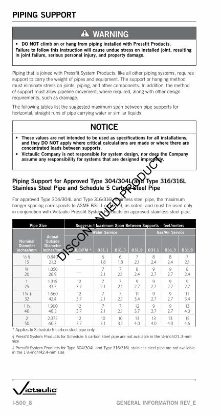
PIPING SUPPORT
WARNINGDO NOT climb on or hang from piping installed with Pressfit Products.•
Failure to follow this instruction will cause undue stress on installed joint, resulting in joint failure, serious personal injury, and property damage.
PipingthatisjoinedwithPressfitSystemProducts,likeallotherpipingsystems,requiressupporttocarrytheweightofpipesandequipment.Thesupportorhangingmethodmusteliminatestressonjoints,piping,andothercomponents.Inaddition,themethodofsupportmustallowpipelinemovement,whererequired,alongwithotherdesignrequirements,suchasdrainage.
Thefollowingtableslistthesuggestedmaximumspanbetweenpipesupportsforhorizontal,straightrunsofpipecarryingwaterorsimilarliquids.
NOTICEThese values are not intended to be used as specifications for all installations, • and they DO NOT apply where critical calculations are made or where there are concentrated loads between supports.victaulic Company is not responsible for system design, nor does the Company • assume any responsibility for systems that are designed improperly.
Piping Support for Approved Type 304/304L and Type 316/316L Stainless Steel Pipe and Schedule 5 Carbon Steel Pipe
ForapprovedType304/304LandType316/316Lstainlesssteelpipe,themaximumhangerspacingcorrespondstoASMEB31.1orB31.9,asnoted,andmustbeusedonlyinconjunctionwithVictaulicPressfitSystemProductsonapprovedstainlesssteelpipe.
Pipe Size Suggested Maximum Span Between Supports – feet/meters
Nominal Diameter
inches/mm
Actual Outside
Diameter inches/mm
Water Service Gas/Air Service
UL/ULC/FM * B31.1 B31.3 B31.9 B31.1 B31.3 B31.9
½ § 0.840 — 6 6 7 8 8 715 21.3 1.8 1.8 2.1 2.4 2.4 2.1
¾ 1.050 — 7 7 8 9 9 820 26.9 2.1 2.1 2.4 2.7 2.7 2.4
1 1.315 12 7 7 9 9 9 925 33.7 3.7 2.1 2.1 2.7 2.7 2.7 2.7
1 1/4 ‡ 1.660 12 7 7 11 9 9 1132 42.4 3.7 2.1 2.1 3.4 2.7 2.7 3.4
1 ½ 1.900 12 7 7 12 9 9 1340 48.3 3.7 2.1 2.1 3.7 2.7 2.7 4.0
2 2.375 12 10 10 13 13 13 1550 60.3 3.7 3.1 3.1 4.0 4.0 4.0 4.6
*AppliestoSchedule5carbonsteelpipeonly
§PressfitSystemProductsforSchedule5carbonsteelpipearenotavailableinthe½-inch/21.3-mmsize
‡PressfitSystemProductsforType304/304LandType316/316Lstainlesssteelpipearenotavailableinthe11/4-inch/42.4-mmsize
DISCONTIN
UED PRODUCT

I-500_9GENERAL INFORMATION REv_E
PIPE PREPARATION
Pipe Condition
ACCEPTABLE
REMOVE BURRS &SHARP EDGES Excessive chamfer on the
pipe I.D. cuts the o-ring during assembly. Excessivechamfer is not acceptable.
Abrasive wheels andsaws leave edges on pipeends that are especially pronounced on one side. Burrs and sharp edges are not acceptable.
Dull wheel cutters pushridges up at the pipe O.D., which causes oversized pipediameters. Oversized pipediameters are not acceptable.
NOT ACCEPTABLE
Square cut pipe is recommended. Burrs and sharp edges mustbe removed from the pipe O.D.
"S" Max.
1. Pipeendsmustbesquarecut(“S”dimensionshownabove)within0.030inch/0.8mm.
2. Cleanandinspectthepipeends.Removeanyscale,rust,orpaintthatmaybepresent.Makesurethepipeendsdonotcontainburrs,sharpedges,raisedweldbeads,andindentationsaminimumof2inches/51mmbackfromthepipeend.
DISCONTIN
UED PRODUCT

I-500_10 GENERAL INFORMATION REv_E
OPERATOR SAFETY REqUIREMENTS FOR PRESSFIT TOOLS
NOTICEAlthough victaulic Pressfit Tools are manufactured for safe, dependable • operation, it is impossible to anticipate the combinations of circumstances that could result in an accident. The following instructions are recommended for safe operation of victaulic Pressfit Tools. Always refer to the specific operating and maintenance instructions manual for complete safety requirements.
1. Read and understand the operating and maintenance instruction manual for the Pressfit Tool.Readthesuppliedmanualcarefullybeforeoperatingorperformingmaintenanceonanytool.Becomefamiliarwiththetool’sfeatures,operations,applications,andlimitations.Beparticularlyawareofitsspecifichazards.Storetheoperator’smanualinareadilyavailablelocation.Ifyourequireadditionalcopiesofanyliterature,contactVictaulic.
2. victaulic Pressfit System Products are designed for use only with approved victaulic stainless steel pipe or UL/ULC-Listed and FM-Approved Schedule 5 steel pipe.
3. Prevent accidental start-ups.Donotcarryatoolwithyourfingeronthetrigger.
4. Ground the PFT505 Electric Pressfit Tool.MakesurethePFT505ElectricPressfitToolisconnectedtoaninternallygroundedelectricalsystem(20ampsmaximum).
5. When using the PFT505 Electric Pressfit Tool, prevent electric shock by avoiding body contact with grounded surfaces (i.e. pipes, radiators, etc.).
6. When the PFT505 Electric Pressfit Tool is used outdoors, use only extension cords suitable for outdoor use.
7. Do not abuse cords.Nevercarrytoolsbythecordoryankitoutofareceptacle.Preventcordsfromcontactingheatsources,oil,andsharpobjects.
8. Operating environment. Donotoperatetoolsindamplocations.Wearhearingprotectioninnoisyshopoperations.Ensurethattheworkareaiswelllit.Avoidlocationsnearflammableliquidsandgaseous,explosiveatmospheres.
9. Keep work areas clean.Keeptheworkareaclearofobstructionsthatcouldlimitthemovementoftheoperator.Cleanupalloilandcoolantspills.
10. Make sure there is adequate space to operate the tool properly.AssemblyofPressfitSystemProductsrequiressufficientspacetoopenthejawsforproperplacementoverfittings.
11. Wear proper clothing.Donotwearunbuttonedjackets,loosesleevecuffs,neckties,oranythingelsethatcanbecometangledinmovingparts.Alwayswearsafetyglassesandfootprotection.Rubberglovesandnon-skidfootweararerecommendedwhenworkingoutdoors.
12. Stay alert.Donotoperatetoolsifyouaredrowsyfrommedicationorfatigue.Avoidhorseplayaroundtools,andkeepbystandersasafedistanceawayfromtheimmediateworkarea.
13. Inspect the equipment.Beforestartingthetool,checkallmoveablepartsforanyobstructions.Makesuretoolcomponentsareinstalledandsecuredproperly.
14. Keep fingers and hands away from press jaws during tool operation.
15. Secure work.Useclamps,vices,orsecuredpipehangerstoholdtheworkandtofreethehandsoftheoperator.
DISCONTIN
UED PRODUCT

I-500_11GENERAL INFORMATION REv_E
16. Do not over-reach.Maintainproperfootingandbalanceatalltimes.
17. Do not misuse tools.Performonlythefunctionsforwhichthetoolwasdesigned.Donotforcethetool.
18. Use only victaulic Pressfit System “press jaws” in the proper size for the product being installed.
19. Disconnect the power cord or remove the battery before servicing tool.Onlyauthorizedpersonnelshouldattempttoservicetools.Alwaysdisconnectthepowersourceorremovethebatterybeforeservicingthetool,changingthepressjaws,ormakinganyadjustments.
20. Always maintain tools.Keeptoolscleanforsafe,dependableoperation.Followallcleaningandlubricatinginstructionsandjawmaintenanceinstructions.Inspecttoolcordsandextensioncordsperiodically.Reportanyunsafeconditionstoauthorizedpersonnelforimmediatecorrection.
21. Check for damaged parts.Checkforalignmentofmovingparts,breakageofparts,mounting,andotherconditionsthatmayaffecttoolorjawoperation.Partsthataredamagedshouldberepairedorreplacedbyanauthorizedservicecenter.Defectiveswitchesshouldbereplacedbyanauthorizedservicecenter.Donotusethetoolifthepowerswitchdoesnotoperateproperly.
22. Do not remove any labels from the tool.Replaceanydamagedorwornlabels.
23. Store Pressfit Tools in a dry, secure area when not in use.
PRESSFIT TOOL RATINGSThePFT505ElectricPressfitTooliscapableofassemblingPressfitSystemProductswithapprovedSchedule5carbonsteelpipein3/4inch/26.9mm,1inch/33.7mm,11/4inch/42.4mm,1½inch/48.3mm,and2inch/60.3mmsizesandapprovedType304/304Land316/316Lstainlesssteelpipein½inch/21.3mm,3/4inch/26.9mm,1inch/33.7mm,1½inch/48.3mm,and2inch/60.3mmsizes.
ThePFT509Battery-PoweredPressfitTooliscapableofassemblingPressfitSystemProductswithapprovedVictaulicSchedule5stainlesssteelpipein½inch/15mm,3/4inch/20mm,1inch/25mm,and1½inch/40mmsizes.
DISCONTIN
UED PRODUCT

I-500_12 GENERAL INFORMATION REv_E
Table I Space Requirement Dimensions – inches/mm
Nominal Diameter
Actual Outside Diameter A C
½ 0.840 2.25 5.2515 21.3 57 133
¾ 1.050 2.25 5.2520 26.9 57 133
1 1.315 2.25 5.2525 33.7 57 133
1 1/4 1.660 2.25 5.2532 42.4 57 133
1 ½ 1.900 4.00 7.0040 48.3 102 178
2 2.375 4.00 7.0050 60.3 102 178
Table II Space Requirement Dimensions – inches/mm
Nominal Diameter
Actual Outside Diameter A B C
½ 0.840 2.25 3.50 5.2515 21.3 57 89 133
¾ 1.050 2.25 3.50 5.2520 26.9 57 89 133
1 1.315 2.25 3.50 5.2525 33.7 57 89 133
1 1/4 1.660 2.25 3.50 5.2532 42.4 57 89 1331 ½ 1.900 4.00 4.00 7.0040 48.3 102 102 178
2 2.375 4.00 4.00 7.0050 60.3 102 102 178
C
A
PRESSFITTINGBEAD
C
A
B
PRESSFITTINGBEAD
SPACE REqUIRED FOR THE PRESSING OPERATION - PFT505 ELECTRIC PRESSFIT TOOLAssemblyofPressfitSystemProductsrequiressufficientspaceforopeningthepressjawsandplacingthemoverthecouplingorfitting.Thetoolmustbeperpendiculartothecouplingorfittingandtheconnectingpipe.
Table III Space Requirement Dimensions – inches/mm
Nominal Diameter
Actual Outside Diameter A B C D
½ 0.840 2.25 3.50 5.25 12.2515 21.3 57 89 133 311
¾ 1.050 2.25 3.50 5.25 12.2520 26.9 57 89 133 311
1 1.315 2.25 3.50 5.25 12.2525 33.7 57 89 133 311
1 1/4 1.660 2.25 3.50 5.25 12.2532 42.4 57 89 133 3111 ½ 1.900 4.00 4.00 7.00 15.0040 48.3 102 102 178 381
2 2.375 4.00 4.00 7.00 15.0050 60.3 102 102 178 381
PRESSFITTINGBEAD
C
A
D
B
DISCONTIN
UED PRODUCT

I-500_13GENERAL INFORMATION REv_E
SPACE REqUIRED FOR THE PRESSING OPERATION - PFT509 BATTERY-POWERED PRESSFIT TOOLAssemblyofPressfitSystemProductsrequiressufficientspaceforopeningthepressjawsandplacingthemoverthecouplingorfitting.Thetoolmustbeperpendiculartothecouplingorfittingandtheconnectingpipe.
Table I Space Requirement Dimensions – inches/mm
Nominal Diameter
Actual Outside Diameter A C
½ 0.840 1.25 3.2515 21.3 31 82
¾ 1.050 1.25 3.2520 26.9 31 82
1 1.315 1.75 3.5025 33.7 44 88
1 ½ 1.900 2.25 5.5040 48.3 57 139
Table II Space Requirement Dimensions – inches/mm
Nominal Diameter
Actual Outside Diameter A B C
½ 0.840 2.00 2.00 3.2515 21.3 50 50 82
¾ 1.050 2.00 2.00 3.2520 26.9 50 50 82
1 1.315 2.50 2.50 4.0025 33.7 63 63 101
1 ½ 1.900 3.00 4.00 6.0040 48.3 76 101 152
Table III Space Requirement Dimensions – inches/mm
Nominal Diameter
Actual Outside Diameter A B C D
½ 0.840 2.00 2.00 3.25 12.5015 21.3 50 50 82 317
¾ 1.050 2.00 2.00 3.25 12.5020 26.9 50 50 82 317
1 1.315 2.50 2.50 4.00 13.0025 33.7 63 63 101 330
1 ½ 1.900 3.00 4.00 6.00 16.0040 48.3 76 101 152 406
C
A
PRESSFITTINGBEAD
PRESSFITTINGBEAD
C
A
B
C
A
B
D
PRESSFITTINGBEADDIS
CONTINUED P
RODUCT

I-500_14 GENERAL INFORMATION REv_E
O-RING SELECTION
CAUTIONTo ensure maximum product performance, always specify the proper grade o-ring • for the intended service.
Failure to select the proper grade o-ring for the service may cause joint failure, resulting in property damage.
Manyfactorsmustbeconsideredforoptimumo-ringperformance.Donotsubjecto-ringstotemperaturesbeyondtherecommendedlimits,sinceexcessivetemperatureswilldegradeo-ringlifeandperformance.Theserviceslistedbelowaregeneralservicerecommendations,andtheyapplyonlytoVictaulico-rings.Recommendationsforaparticularservicedonotnecessarilyimplycompatibilityofthecouplings,relatedfittings,orothercomponentsforthesameservice.AlwaysrefertothelatestVictaulicGasketSelectionGuide(05.01)forservicerecommendations.
NOTICEO-rings for stainless steel Pressfit Products contain two color code marks.• O-rings for carbon steel Pressfit Products contain only one color code mark.• O-rings for stainless steel Pressfit Products CANNOT be interchanged with • o-rings for carbon steel Pressfit Products.
GradeTemperature
Range CompoundColor Code * General Service Recommendations
Standard O-Ring
E –30°Fto+230°F/–34°Cto+110°C
EPDM Green
Recommended for hot water service within the specified temperature range, plus a variety of dilute acids, oil-free air, and many chemical services. UL classi-fied in accordance with ANSI/NSF 61 for cold +86°F/+30°C and hot +180°F/+82°C potable water service.
NOT RECOMMENDED FOR PETROLEUM SERVICES AND STEAM SERVICES.
Available O-Ring
T –20°Fto+180°F/–29°Cto+82°C
NitrileOrangeStripe
Recommended for petroleum products, hydrocarbons, compressed air, air with oil vapors, vegetable oil, and mineral oil, within the specified temperature range.
NOT RECOMMENDED FOR HOT WATER SERVICES OVER +150°F/+66°C OR FOR HOT, DRY AIR OVER +140°F/+60°C.
Optional O-Ring
O +20°Fto+300°F/–7°Cto+149°C
Fluoro-elastomer
BlueStripe
Recommended for many oxidizing acids, petroleum oils, halogenated hydrocar-bons, lubricants, hydraulic fluids, organic liquids, and air with hydrocarbons to +300°F/+149°C.
NOT RECOMMENDED FOR STEAM SERVICES.
*Pressfitsteelandstainlesssteelproductsmustbeusedonlyonservicesthatarecompatiblewiththeo-ringandfittingmaterials.Incompatibleservicesmayresultinleakage.Forservicesnotlisted,orforspecialservices,contactVictaulicforrecommendations.RefertotheVictaulicGasketSelectionGuide(05.01)forspecificrecommendations.
DISCONTIN
UED PRODUCT

I-500_15
InstallationInstructionsfor Pressfit
System ProductsAll Configurations
DISCONTIN
UED PRODUCT

I-500_16INSTALLATION INSTRUCTIONS FOR
PRESSFIT SYSTEM PRODUCTS REv_E
PRODUCT INSTALLATION
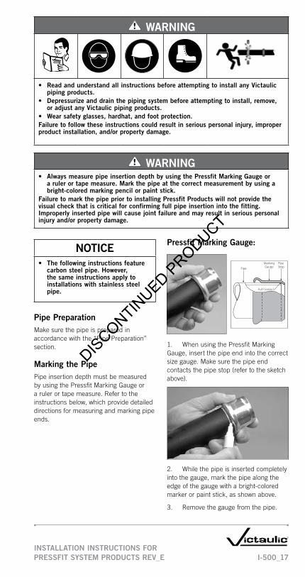
WARNINGBefore operating any Victaulic pipe preparation tools, • read and understand the operating and maintenance instructions manual for the tool.Learn the operation, applications, and potential hazards • peculiar to the tool.
Failure to follow these instructions could result in serious personal injury, property damage, product damage, and improper product installation.
O-RingO-RingPocket O-RingPipe Stop
BeadInsertion
Mark Housing Press�t ToolIndent
Patented
Exaggerated for Clarity
UNPRESSED PRESSED
ThefollowinginstructionscontainimportantinformationregardinginstallationofVictaulicPressfitSystemProducts.Theseinstructionsmustbefollowedtoensureproperjointperformance.
Alwayscheckthesuppliedo-ringtoensureitissuitablefortheintendedservice.Refertothe“O-RingSelection”sectionfordetails.NOTE:O-ringsforstainlesssteelPressfitProductscontaintwocolorcodemarks,ando-ringsforcarbonsteelPressfitProductscontainonlyonecolorcodemark.O-ringsforstainlesssteelPressfitProductsCANNOTbeinterchangedwitho-ringsforcarbonsteelPressfitProducts.
AlwaysreadtheoperatingandmaintenanceinstructionsmanualforthePressfitTool.
Pipedimensionsmustbewithinpublishedtolerances;thesetolerancesaresubjecttospecifiedstandardsforacceptability.Refertothe“PipeSpecifications”sectionfordetails.
AlwaysmeasuretheinsertiondepthbyusingthePressfitMarkingGaugeorarulerortapemeasure.Placeamarkattheproperinsertion-depthmeasurement.Thismarkiscriticalasanindicatorforfullinsertionofthepipeendintothefitting(refertothe“InstallationInstructions”section).
Pressfito-ringsMUSTBELUBRICATED.Lubricationisessentialtopreventpinchingortearingofo-ringsduringinstallation.Useasoapywatersolution,liquidsilicone,orathincoatofVictauliclubricantontheo-rings.WHENUSINGVICTAULICLUBRICANT,DONOTOVER-LUBRICATETHEO-RINGS.AverythincoatofVictauliclubricantissufficientforproperinstallation.
PressfitSystemProductshaveuniquecenter-to-endorend-to-enddimensionswithuniform“takeout”dimensions.Threadedproductswithspecialfeaturessuchasprobes,escutcheoncups,etc.,mustbecheckedtoensurethethreadstandardandinsertionlengtharecompatiblewithfittingdimensions.Failuretoverifydimensionalsuitabilitymayresultindifficultand/orimproperassembly.
DISCONTIN
UED PRODUCT
I-500_17INSTALLATION INSTRUCTIONS FOR PRESSFIT SYSTEM PRODUCTS REv_E
WARNING
Read and understand all instructions before attempting to install any victaulic • piping products.Depressurize and drain the piping system before attempting to install, remove, • or adjust any Victaulic piping products.Wear safety glasses, hardhat, and foot protection.•
Failure to follow these instructions could result in serious personal injury, improper product installation, and/or property damage.
WARNINGAlways measure pipe insertion depth by using the Pressfit Marking Gauge or • a ruler or tape measure. Mark the pipe at the correct measurement by using a bright-colored marking pencil or paint stick.
Failure to mark the pipe prior to installing Pressfit Products will not provide the visual check that is critical for confirming full pipe insertion into the fitting. Improperly inserted pipe will cause joint failure and may result in serious personal injury and/or property damage.
NOTICEThe following instructions feature • carbon steel pipe. However, the same instructions apply to installations with stainless steel pipe.
Pipe PreparationMakesurethepipeispreparedinaccordancewiththe“PipePreparation”section.
Marking the PipePipeinsertiondepthmustbemeasuredbyusingthePressfitMarkingGaugeorarulerortapemeasure.Refertotheinstructionsbelow,whichprovidedetaileddirectionsformeasuringandmarkingpipeends.
Pressfit Marking Gauge:
Pipe
MarkingGauge
PipeStop
Full Contact
1. WhenusingthePressfitMarkingGauge,insertthepipeendintothecorrectsizegauge.Makesurethepipeendcontactsthepipestop(refertothesketchabove).
2. Whilethepipeisinsertedcompletelyintothegauge,markthepipealongtheedgeofthegaugewithabright-coloredmarkerorpaintstick,asshownabove.
3. Removethegaugefromthepipe.
DISCONTIN
UED PRODUCT

I-500_18INSTALLATION INSTRUCTIONS FOR
PRESSFIT SYSTEM PRODUCTS REv_E
Ruler or Tape Measure:
1. Whenusingarulerortapemeasure,refertothe“PressfitInsertionDepthRequirements”tablebelow.Measurebackfromthepipeend.Placeamarkaroundthepipecircumferencewithabright-coloredmarkingpencilorpaintstick,asshownabove.
Pressfit Insertion Depth Requirements
Nominal Diameter
inches/mm
Actual Outside
Diameter inches/mm
Insertion Depth Req. inches/mm
½ 0.840 7/815 21.3 22
¾ 1.050 120 26.9 25
1 1.315 125 33.7 25
1 1/4 1.660 1 1/432 42.4 32
1 ½ 1.900 1 ½40 48.3 38
2 2.375 1 7/850 60.3 48
Pressfit Slip Couplings:PressfitSlipCouplingsdonotcontainapipestopsothatinsertiontovariousdepthscanbeaccommodated.Forproperassembly,thepipemustbeinsertedintothefittingtotheminimumdepthlistedinthe“PressfitSlipCouplingMinimumInsertionDepthRequirements”tablebelow.
1. Refertothe“PressfitSlipCouplingMinimumInsertionDepthRequirements”tablebelow.Usearulerortapemeasuretomeasurebackfromthepipeend.Placeamarkaroundthepipecircumferencewithabright-coloredmarkingpencilorpaintstick,asshownabove.
Pressfit Slip Coupling Minimum Insertion Depth Requirements
Nominal Diameter
inches/mm
Actual Outside
Diameter inches/mm
Insertion Depth Req. inches/mm
½ 0.840 7/815 21.3 22
¾ 1.050 120 26.9 25
1 1.315 125 33.7 25
1 1/4 1.660 132 42.4 25
1 ½ 1.900 140 48.3 25
2 2.375 1 1/450 60.3 32
DISCONTIN
UED PRODUCT

I-500_19INSTALLATION INSTRUCTIONS FOR PRESSFIT SYSTEM PRODUCTS REv_E
Product Assembly:
1. CheckPressfitProductopeningstomakesureo-ringsareseatedproperlyinsidetheo-ringpocket.Makesureo-ringsarethepropermaterialgradefortheintendedservice.
1a. Ifanydirtordebrisispresent,removetheo-ringsfromtheo-ringpocket.Cleantheo-ringswithwater,andreplacethemproperlyintheo-ringpocket.Makesurenogreaseoroilresidueispresentontheo-rings.
CAUTION• DO NOT force the pipe into the
coupling or fitting.Forcing the pipe into position may cause damage to the o-ring, resulting in joint leakage and/or property damage.
2. PressfitO-ringsMUSTBELUBRICATED.LubricationisessentialtopreventpinchingortearingofO-ringsduringinstallation.Useasoapywatersolution,liquidsilicone,orathincoatofVictauliclubricantontheO-rings.WHEN USING vICTAULIC LUBRICANT, DO NOT OvER-LUBRICATE THE O-RINGS.AverythincoatofVictauliclubricantissufficientforproperinstallation.
CAUTION• DO NOT force the pipe into the
coupling or fitting.Forcing the pipe into position may cause damage to the o-ring, resulting in joint leakage and/or property damage.
3. For Standard Couplings and Fittings:Insertthepipeintothecouplingorfittingwithaslighttwistingactiontoeaseinsertion.Thepipemustcontactthepipestopinsidethecouplingorfitting.Makesurethepipeisinsertedfullyuptothemarkthatwasmadeinprevioussteps.
3a. For Slip Couplings:Insertthepipeintotheslipcouplingwithaslighttwistingactiontoeaseinsertion.Sinceslipcouplingsdonotcontainapipestop,makesurethepipeisinsertedfullyuptothemarkthatwasmadeinthe“PressfitSlipCoupling”section.
DISCONTIN
UED PRODUCT
I-500_20INSTALLATION INSTRUCTIONS FOR
PRESSFIT SYSTEM PRODUCTS REv_E
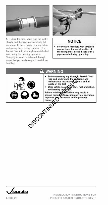
4. Alignthepipe.Makesurethejointisstraightandthepipemarksindicatefullinsertionintothecouplingorfittingbeforeperformingthepressingoperation.ThePressfitToolwillnotstraightenadeflectedjointduringthepressingoperation.Straightjointscanbeachievedthroughproperhangerpositioningandcarefultoolhandling.
NOTICEFor Pressfit Products with threaded • connections, the outlet section of the fitting must be held rigid with a pipe wrench during tightening.
WARNINGBefore operating any victaulic Pressfit Tools, • read and understand the operating and maintenance instructions manual and all labels on the tool.Wear safety glasses, hardhat, foot protection, • and hearing protection.
Failure to follow instructions may result in serious personal injury, improper tool operation, improper joint assembly, and/or property damage.
DISCONTIN
UED PRODUCT

I-500_21INSTALLATION INSTRUCTIONS FOR PRESSFIT SYSTEM PRODUCTS REv_E
INSTALLATION INSPECTION
WARNINGAlways inspect each joint to ensure proper product • installation.Undersized or oversized pipe and improperly pressed • fittings are unacceptable. Any of these conditions must be corrected before attempting to pressurize the system.
Failure to follow these instructions could result in serious personal injury, property damage, joint leakage, and/or joint failure.
PROPER PRESS
Pipe Ends Inserted Fully, Both Ends Pressed Properly
Properpipepreparationandproperpressingofcouplingsorfittingsisessentialformaximumjointperformance.THESE CONDITIONS MUST BE PRESENT TO ENSURE PROPER JOINT ASSEMBLY.
1. Re-inspectalljointsbeforeandafterthefieldtesttoidentifypotentialfailurepoints.
2. Inspectthepressedjoint,andcompareittothephotosshownbelow.Ifthepressedjointdoesnotlooklikethephotolabeled“ProperPress,”thejointmustbecutout,andanewcouplingorfittingmustbeinstalled.
IMPROPER PRESSES (NOT ACCEPTABLE)
Pipe End Not Inserted Fully Right Side Not Fully Pressed
Not Pressed Correctly Due to Incorrect Press Jaw Placement
Press Resulting from Improperly Maintained Press Jaws
DISCONTIN
UED PRODUCT

I-500_22
DISCONTIN
UED PRODUCT
I-500_23PRODUCT DATA REv_E
Product Data
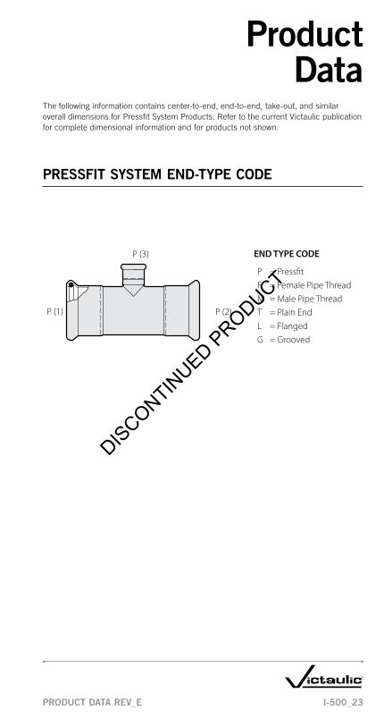
Thefollowinginformationcontainscenter-to-end,end-to-end,take-out,andsimilaroveralldimensionsforPressfitSystemProducts.RefertothecurrentVictaulicpublicationforcompletedimensionalinformationandforproductsnotshown.
PRESSFIT SYSTEM END-TYPE CODE
P (3)
P (1) P (2)
P = Press�tF = Female Pipe ThreadM = Male Pipe ThreadT = Plain EndL = FlangedG = Grooved
END TYPE CODE
DISCONTIN
UED PRODUCT

I-500_24 PRODUCT DATA REv_E
PRESSFIT SYSTEM FITTINGS
Styles 505, 507, and 597 – Standard Coupling (P x P)
UE to E
STYLES 505, 507, 597
Size Dimensions – inches/mm
Nominal Size
inches/ mm
Actual Outside Diameter
inches/ mm E to E
U Takeout
½ * 0.840 2.00 0.3515 21.3 51 9
¾ 1.050 2.17 0.2820 26.7 55 7
1 1.315 2.44 0.3925 33.7 62 10
1 1/4 # 1.660 2.76 0.3932 42.4 70 101 ½ 1.900 3.15 0.3240 48.3 80 8
2 2.375 3.94 0.3350 60.3 100 8
*Style505forcarbonsteelpipeisnotavailableinthe½-inch/21.3-mmsize
#Styles507and597forstainlesssteelpipearenotavailableinthe11/4-inch/42.4-mmsize
Styles 506 and 508 – Slip Coupling (P x P)E to E
Imin.
Imin.
STYLES 506, 508
Size Dimensions – inches/mm
Nominal Size
inches/ mm
Actual Outside Diameter
inches/ mm E to E
I Minimum Tube
Insertion
½ * 0.840 3.31 1.0015 21.3 84 25
¾ 1.050 3.54 1.0020 26.7 90 25
1 1.315 3.94 1.0025 33.7 100 25
1 1/4 # 1.660 4.33 1.0032 42.4 110 251 ½ 1.900 4.72 1.0040 48.3 120 25
2 2.375 5.51 1.2550 60.3 140 32
*Style506forcarbonsteelpipeisnotavailableinthe½-inch/21.3-mmsize
#Style508forstainlesssteelpipeisnotavailableinthe11/4-inch/42.4-mmsize
DISCONTIN
UED PRODUCT

I-500_25PRODUCT DATA REv_E
PRESSFIT SYSTEM FITTINGS
Styles 510, 570, and 590 – 90° Elbow (P x P)Styles 509, 568, and 586 – Short Tangent 90° Elbow (P x P)Style 511, 571, and 591 – 45° Elbow (P x P)
C to PEU
STYLES 510, 570, 590
UC to PE
STYLES 509, 568, 586
CtoPE
U
STYLES 511, 571, 591
SizeStyles 510, 570, 590
90° Elbows
Styles 509, 568, 586 Short Tangent 90°
ElbowsStyles 511, 571, 591
45° Elbows
Nominal Size
inches/ mm
Actual Outside Diameter inches/
mm
C to PE inches/
mm
U Takeout inches/
mm
C to PE inches/
mm
U Takeout inches/
mm
C to PE inches/
mm
U Takeout inches/
mm
½ * 0.840 2.67 1.84 — — 1.65 0.8215 21.3 68 47 42 21
¾ 1.050 3.43 2.48 2.83 1.88 2.44 1.5020 26.7 87 63 72 48 62 38
1 1.315 4.33 3.31 3.36 2.34 3.11 2.0925 33.7 110 84 85 59 79 53
1 1/4 # 1.660 5.79 4.60 4.02 2.83 4.25 3.0732 42.4 147 117 102 72 108 781 ½ 1.900 6.73 5.32 4.60 3.19 5.00 3.5940 48.3 171 135 117 81 127 91
2 2.375 8.19 6.38 5.71 3.90 6.02 4.2250 60.3 208 162 145 99 153 107
*Styles510,509,and511forcarbonsteelpipearenotavailableinthe½-inch/21.3-mmsize
#Styles570,590,568,586,571,and591forstainlesssteelpipearenotavailableinthe11/4-inch/42.4-mmsize
DISCONTIN
UED PRODUCT

I-500_26 PRODUCT DATA REv_E
PRESSFIT SYSTEM FITTINGS
Styles 520, 572, and 592 – Tee (P x P x P)
U2
C to PE
Cto
EOB
U1
STYLES 520, 572, 592
Size Dimensions – inches/mm
Nominal Size
inches/ mm
Actual Outside
Diameter inches/
mm C to PE U1 C to EOB U2
½ * 0.840 1.40 1.04 1.60 0.7215 21.3 36 26 41 18
¾ 1.050 1.89 1.89 1.89 0.9520 26.7 48 48 48 24
1 1.315 2.11 2.17 2.15 1.1325 33.7 54 55 55 29
1 1/4 # 1.660 2.44 2.51 2.48 1.2932 42.4 62 64 63 331 ½ 1.900 2.76 2.69 2.80 1.3940 48.3 70 68 71 35
2 2.375 3.39 3.17 3.62 1.8150 60.3 86 81 92 46
*Style520forcarbonsteelpipeisnotavailableinthe½-inch/21.3-mmsize
#Styles572and592forstainlesssteelpipearenotavailableinthe11/4-inch/42.4-mmsize
DISCONTIN
UED PRODUCT

I-500_27PRODUCT DATA REv_E
PRESSFIT SYSTEM FITTINGS
Style 520 – Tee Reducing Branch (P x P x F)
Cto
EOBU2
*
C to PEU1
STYLE 520
Size Dimensions – inches/mm
Nominal Size
inches/ mm C to PE U1 C to EOB U2
¾ × ¾ × ½ 1.89 1.89 1.70 1.1720 20 15 48 48 43 30
1 × 1 × ½ 2.11 2.17 1.68 1.1525 25 15 54 55 43 29
¾ 2.11 2.17 1.68 1.1320 54 55 43 29
1 2.11 2.17 2.00 1.3225 54 55 51 34
1 1/4 × 1 1/4 × ½ 2.44 2.51 1.86 1.3332 32 15 62 64 47 34
¾ 2.44 2.51 1.86 1.3120 62 64 47 33
1 2.44 2.51 2.08 1.4025 62 64 53 36
1 ½ × 1 ½ × ½ 2.76 2.69 1.98 1.4540 40 15 70 68 51 37
¾ 2.76 2.69 1.90 1.3520 70 68 48 34
1 2.76 2.69 2.20 1.6225 70 68 56 41
2 × 2 × ½ 3.39 3.16 2.21 1.6850 50 15 86 80 56 43
¾ 3.39 3.16 2.10 1.5520 86 80 53 39
1 3.39 3.16 2.43 1.7525 86 80 62 45
DISCONTIN
UED PRODUCT

I-500_28 PRODUCT DATA REv_E
PRESSFIT SYSTEM FITTINGS
Style 520 – Tee Reducing Branch (P x P x P)
STYLE 520
Size Dimensions – inches/mm
Nominal Size
inches/ mm C to PE U1 C to EOB U2
1 × 1 × ¾ 2.11 2.17 2.03 1.0825 25 20 54 55 52 27
1 1/4 × 1 1/4 × ¾ 2.44 2.51 2.10 1.1532 32 20 62 64 53 29
1 2.44 2.51 2.20 1.1825 62 64 56 30
1 ½ × 1 ½ × ¾ 2.76 2.69 2.20 1.2540 40 20 70 68 56 32
1 2.76 2.69 2.44 1.4225 70 68 62 36
2 × 2 × ¾ 3.39 3.16 2.40 1.4550 50 20 86 80 61 37
1 3.39 3.16 2.60 1.5825 86 80 66 401 ½ 3.39 3.16 3.00 1.5840 86 80 76 40
Cto
EOBU2
C to PEU1
DISCONTIN
UED PRODUCT

I-500_29PRODUCT DATA REv_E
PRESSFIT SYSTEM FITTINGS
Styles 578 and 588 – Tee with Threaded Branch (P x P x F)
Cto
EOBU2
*
C to PEU1
STYLES 578, 588
Size Dimensions – inches/mm
Nominal Size
inches/ mm C to PE U1 C to EOB U2
½ × ½ × ½ 1.50 1.35 1.50 0.9715 15 15 38 34 38 25
¾ × ¾ × ½ 1.89 1.89 1.64 1.1120 20 15 48 48 42 28
¾ 1.89 1.89 1.71 1.1620 48 48 43 29
1 × 1 × ½ 2.11 2.17 1.78 1.2525 25 15 54 55 45 32
¾ 2.11 2.17 1.85 1.3020 54 55 47 33
1 2.11 2.17 2.02 1.3425 54 55 51 34
1 ½ × 1 ½ × ½ 2.76 2.69 2.07 1.5440 40 15 70 68 53 39
¾ 2.76 2.69 2.14 1.5920 70 68 54 40
1 2.76 2.69 2.31 1.6325 70 68 59 40
2 × 2 × ½ 3.39 3.16 2.31 1.7850 50 15 86 80 59 45
¾ 3.39 3.16 2.38 1.8320 86 80 60 46
1 3.39 3.16 2.55 1.8725 86 80 65 48
DISCONTIN
UED PRODUCT

I-500_30 PRODUCT DATA REv_E
PRESSFIT SYSTEM FITTINGS
Styles 573 and 593 – Tee with Reducing Branch (P x P x P)
Cto
EOBU2
C to PEU1
STYLES 573, 593
Size Dimensions – inches/mm
Nominal Size
inches/ mm C to PE U1 C to EOB U2
¾ × ¾ × ½ 1.90 1.91 2.10 1.2720 20 15 48 48 53 32
1 × 1 × ½ 2.10 2.15 2.30 1.4725 25 15 53 55 58 37
¾ 2.11 2.17 2.03 1.0920 54 55 52 28
1 ½ × 1 ½ × ½ 2.76 2.69 2.60 1.7740 40 15 70 68 66 45
¾ 2.76 2.69 2.32 1.6820 70 68 59 43
1 2.76 2.69 2.44 1.4225 70 68 62 36
2 × 2 × ½ 3.39 3.17 2.80 1.9750 50 15 86 81 71 50
¾ 3.39 3.17 2.56 1.6220 86 81 65 41
1 3.39 3.17 2.68 1.6625 86 81 68 42
1 ½ 3.39 3.17 3.03 1.6240 86 81 77 41
DISCONTIN
UED PRODUCT

I-500_31PRODUCT DATA REv_E
PRESSFIT SYSTEM FITTINGS
Style 520 – End-of-Line Tee (P x C x F)
Cto
EOBU2
U1C to PE C to E
*
STYLE 520
Size Dimensions – inches/mm
Nominal Size
inches/ mm C to PE U1 C to EOB U2 C to E
1 × @ 2.11 2.17 @ @ 2.9025 @ 54 55 @ @ 74
1 1/4 × @ 2.44 2.51 @ @ 3.3032 @ 62 64 @ @ 84
1 ½ × @ 2.76 2.69 @ @ 3.6040 @ 70 68 @ @ 91
2 × @ 3.39 3.16 @ @ 4.2050 @ 86 80 @ @ 107
@Factory-assembledcapisaddedtotheStyle520teewith(A)threadedreducingbranchor(B)Pressfitreducingbranch.Therunsize,outletsize,andoutletstyle(threadedorPressfit)mustbespecifiedontheorder.
Style 535 – Cross (P x P)U1
U2
C to�EOB1
C�to�
EOB2
STYLE 535
Size Dimensions – inches/mm
Nominal Size
inches/ mm
Actual Outside
Diameter inches/
mm C to EOB1 C to EOB2 Takeout U1 Takeout U2
¾ 1.050 1.90 1.80 1.89 1.7020 26.7 48 46 48 43
1 1.315 2.10 2.10 2.16 2.1625 33.7 53 53 55 55
1 1/4 1.660 2.40 2.50 2.42 2.6232 42.4 61 64 62 671 ½ 1.900 2.80 2.80 2.78 2.7840 48.3 71 71 71 71
2 2.375 3.40 3.60 3.17 3.5850 60.3 86 91 81 91
DISCONTIN
UED PRODUCT

I-500_32 PRODUCT DATA REv_E
PRESSFIT SYSTEM FITTINGS
Styles 576 and 596 – Male Threaded Adapter (P x M)
E to EIL *U
STYLES 576, 596
Size Dimensions – inches/mm
Nominal Size
inches/ mm E to E
U Takeout
IL Insertion Length
½ × ½ 3.68 2.32 0.8315 15 93 59 21
¾ × ½ 3.22 1.75 0.9520 15 82 44 24
¾ 3.72 2.22 0.9520 94 56 24
1 3.22 1.60 0.9525 82 41 24
1 × ¾ 3.34 1.77 1.0225 20 85 45 26
1 4.02 2.32 1.0225 102 59 26
1 ½ × ¾ 3.69 1.73 1.4240 20 94 44 36
1 ½ 4.40 2.27 1.4240 112 58 36
2 × 2 5.03 2.46 1.8150 50 128 62 46
DISCONTIN
UED PRODUCT

I-500_33PRODUCT DATA REv_E
PRESSFIT SYSTEM FITTINGS
Style 580 – Male Threaded Adapter (P x M)
U *ILE to E
STYLE 580
Size Dimensions – inches/mm
Nominal Size
inches/ mm E to E
U Takeout
IL Insertion Length
¾ × ½ 2.53 1.05 0.9520 15 64 27 24
¾ 2.53 1.03 0.9520 64 26 24
1 2.84 1.21 0.9525 72 31 24
1 × ¾ 2.65 1.08 1.0225 20 67 27 26
1 2.96 1.26 1.0225 75 32 26
1 1/4 × 1 1/4 3.13 1.23 1.1932 32 80 31 301 ½ × 1 ½ 3.35 1.22 1.4240 40 85 31 36
2 × 2 3.93 1.36 1.8150 50 100 35 46
DISCONTIN
UED PRODUCT

I-500_34 PRODUCT DATA REv_E
PRESSFIT SYSTEM FITTINGS
Styles 579 and 599 – Female Threaded Adapter (P x F)E to E
UIL *
STYLES 579, 599
Size Dimensions – inches/mm
Nominal Size
inches/ mm E to E
U Takeout
IL Insertion Length
½ × ½ 2.15 0.79 0.8315 15 55 20 21
¾ × ½ 2.20 0.71 0.9520 15 56 18 24
¾ 2.20 0.79 0.9520 56 20 24
1 × ½ 2.30 0.75 1.0225 15 58 19 26
¾ 2.30 0.73 1.0220 58 19 26
1 2.40 0.75 1.0225 61 19 26
1 ½ × 1 2.96 0.92 1.4240 25 75 23 36
1 ½ 2.96 0.87 1.4240 75 22 36
2 × 1 ½ 3.75 1.27 1.8150 40 95 32 46
2 3.75 1.27 1.8150 95 32 46
Style 580 – Female Threaded Adapter (P x F)
ILE to E
*U
STYLE 580
Size Dimensions – inches/mmNominal
Size inches/
mm E to EU
TakeoutIL
Insertion Length
¾ × ½ 1.84 0.36 0.9520 15 47 9 24
¾ 2.16 0.67 0.9520 55 17 24
1 × ½ 1.96 0.40 1.0225 15 50 10 26
¾ 1.96 0.39 1.0220 50 10 26
1 2.46 0.75 1.0225 63 19 26
DISCONTIN
UED PRODUCT

I-500_35PRODUCT DATA REv_E
PRESSFIT SYSTEM FITTINGS
Styles 550, 582, and 583 – Reducer Insert (T x P)E to E
U IL
STYLES 550, 582, 583
Size Dimensions – inches/mm
Nominal Size
inches/ mm E to E
U Takeout
IL Insertion Length
1 × ¾ 2.95 0.98 0.9525 20 75 25 24
1 1/4 * × ¾ * 3.50 1.37 0.9532 20 89 35 24
1 * 3.31 1.10 1.0225 84 28 26
1 ½ * × 1 * 3.66 1.22 1.0240 25 93 31 26
1 1/4 * 3.66 1.06 1.1932 93 27 30
2 * × 1 1/4 * 4.33 1.34 1.1950 32 110 34 30
1 ½ 4.33 1.11 1.4240 110 28 36
*Styles582and583arenotavailableinthesesizes
Styles 584 and 585 – Threaded Union (P x P)E to E
U
STYLES 584, 585
Size Dimensions – inches/mm
Nominal Size
inches/ mm
Actual Outside Diameter
inches/ mm E to E
U Takeout
½ 0.840 7.02 5.2715 21.3 178 134
¾ 1.050 7.14 5.1420 26.7 181 131
1 1.315 7.26 5.2625 33.7 184 134
1 ½ 1.900 8.44 5.4440 48.3 214 138
2 2.375 8.38 4.6750 60.3 213 119
DISCONTIN
UED PRODUCT

I-500_36 PRODUCT DATA REv_E
PRESSFIT SYSTEM FITTINGS
Style 561 – Weld Adapter (P x T)E to E
UIL
STYLE 561
Size Dimensions – inches/mm
Nominal Size
inches/ mm E to E
U Takeout
IL Insertion Length
½ × ½ 3.68 2.85 0.8315 15 93 72 21
¾ × ¾ 3.72 2.77 0.9520 20 94 70 24
1 × 1 4.02 3.00 1.0225 25 102 76 26
1 ½ × 1 ½ 4.40 2.98 1.4240 40 112 76 36
2 × 2 5.03 3.22 1.8150 50 128 82 46
Styles 574 and 594 – Concentric Reducer (T x T)E to E
L1 L2
InsertionMark
STYLES 574, 594
Size Dimensions – inches/mm
Nominal Size
inches/ mm E to E
L1 Minimum
L 2 Minimum
¾ × ½ 3.50 1.00 0.8820 15 89 25 22
1 × ½ 3.56 1.03 0.8825 15 90 26 22
¾ 3.56 1.03 1.0020 90 26 25
1 ½ × ½ 4.25 1.44 0.8840 15 108 37 22
¾ 4.25 1.44 1.0020 108 37 25
1 4.25 1.44 1.0325 108 37 26
2 × ½ 5.00 1.81 0.8850 15 127 46 22
¾ 5.00 1.81 1.0020 127 46 25
1 5.00 1.81 1.0325 127 46 26
1 ½ 5.00 1.81 1.4440 127 46 37
DISCONTIN
UED PRODUCT

I-500_37PRODUCT DATA REv_E
PRESSFIT SYSTEM FITTINGS
Styles 577 and 587 – Transition Nipple (G x T)E to E
InsertionMark
L1
STYLES 577, 587
Size Dimensions – inches/mm
Nominal Size
inches/ mm
Actual Outside Diameter
inches/ mm E to E
L1 Minimum
¾ 1.050 4.00 1.0020 26.7 102 25
1 1.315 4.00 1.0025 33.7 102 25
1 ½ 1.900 4.00 1.5040 48.3 102 38
2 2.375 4.00 1.8850 60.3 102 48
Styles 575 and 595 – Flange Adapter (P x L)
U
X
Z
W Y
STYLES 575, 595
Size Dimensions – inches/mm
Nominal Size
inches/ mm
Actual Out. Dia. inches/
mmU
Takeout W X Y Z
½ 0.840 2.39 1.38 2.38 3.50 3.2215 21.3 61 35 60 89 82
¾ 1.050 2.27 1.69 2.75 3.88 3.2220 26.7 58 43 70 99 82
1 1.315 2.27 2.00 3.12 4.25 3.2925 33.7 58 51 79 108 84
1 ½ 1.900 2.07 2.88 3.88 5.00 3.4840 48.3 53 73 99 127 88
2 2.375 1.80 3.62 4.75 6.00 3.6050 60.3 46 92 121 152 92
DISCONTIN
UED PRODUCT

I-500_38 PRODUCT DATA REv_E
PRESSFIT SYSTEM FITTINGS
Styles 565 and 566 – van Stone Flange Adapter (P x L)
E to E
STYLE 565, 566
Size Dimensions
Nominal Size
inches/ mm
Actual Outside Diameter
inches/ mm
E to E inches/
mm
½ 0.840 3.1215 21.3 79
¾ 1.050 3.1720 26.7 81
1 1.315 3.2825 33.7 83
1 ½ 1.900 3.6440 48.3 93
2 2.375 4.7350 60.3 120
DISCONTIN
UED PRODUCT

I-500_39PRODUCT DATA REv_E
PRESSFIT SYSTEM BALL vALvES
Series 522 – Brass Body Ball valve with Carbon Steel Pressfit Ends (P x P)
F
C
UA
SERIES 522
Size Dimensions – inches/mm
Nominal Size
inches/ mm
Actual Outside
Diameter inches/mm
A End to End C F
U Takeout
¾ 1.050 6.50 1.79 3.78 4.6120 26.7 165 45 96 117
1 1.315 7.62 1.95 3.78 5.5725 33.7 194 50 96 142
1 1/4 1.660 8.20 2.17 3.78 5.8232 42.4 208 55 96 148
1 ½ 1.900 9.00 2.68 5.43 6.1740 48.3 229 68 138 157
2 2.375 10.70 2.89 5.43 7.0950 60.3 272 73 138 180
DISCONTIN
UED PRODUCT

I-500_40 PRODUCT DATA REv_E
PRESSFIT SYSTEM BALL vALvES
Series 569 – vic-Press 316™ Type 316 Stainless Steel Ball valve
DO
NO
T TR
IM D
O N
OT TRIM
E
B
A
C
E
B
A
PLAIN-END X PLAIN-END (T X T) GROOvED X GROOvED (G X G)
DO
NO
T TR
IM
E
B
A
C
PLAIN-END X GROOvED (T X G)
Size Dimensions – inches/mm
Nominal Size
inches/ mm
Actual Outside
Diameter inches/
mmA
End to End B C E
½* 0.840 7.98 2.36 0.88 5.1215 21.3 200.0 59.9 22.4 130.0
¾ 1.050 8.57 2.52 1.00 5.1220 26.7 217.2 64.0 25.4 130.0
1 1.315 8.89 2.80 1.00 6.5025 33.7 225.8 71.1 25.4 165.1
1 ½ 1.900 11.20 3.39 1.50 7.4840 48.3 284.5 86.1 38.1 190.0
2 2.375 12.52 3.74 1.88 7.4850 60.3 318.0 95.0 47.8 190.0
Fordimensionswithgearoperator,contactVictaulic.
*The½-inch/15-mmsizeisavailableonlyintheplainendxplainend(TxT)configuration.
DISCONTIN
UED PRODUCT

I-500_41PRODUCT DATA REv_E
PRESSFIT SYSTEM BALL vALvES
Series 589 – vic-Press 304™ Brass Body Ball Valve with Stainless Steel Pressfit Ends (P x P)
C
F
AU
SERIES 589
Size Dimensions – inches/mm
Nominal Size
inches/ mm
Actual Outside
Diameter inches/mm
A End to End C F
U Takeout
½ 0.840 8.49 1.33 3.07 6.8415 21.3 216 34 78 174
¾ 1.050 8.88 1.79 3.78 6.9920 26.7 226 46 96 178
1 1.315 9.74 1.95 3.78 7.6925 33.7 247 50 96 195
1 ½ 1.900 11.09 2.68 5.43 8.2640 48.3 282 68 138 210
2 2.375 12.90 2.89 5.43 9.2950 60.3 328 73 138 236
DISCONTIN
UED PRODUCT

I-500_42 PRODUCT DATA REv_E
PRESSFIT SYSTEM GROOvED-END UNION
Style 547 – Grooved-End Union
InsertionMark
• Style547groovedendunionscanbeformedwithtwoStyle587transitionnipplesandavarietyofgrooved-endcouplings.
• Whereexternalcorrosionisnotaconcern,useStyle77CouplingsforflexiblejointsorStyle07Couplingsforrigidjoints.
• Whereexternalcorrosionisaconcern,useStyle77S/475CouplingsforflexiblejointsorStyle489Couplingsforrigidjoints.
• Followtheinstructions,suppliedwiththecoupling,toensureproperassembly.
DISCONTIN
UED PRODUCT

I-500_4
I-500FIELD INSTALLATION HANDBOOK
UPDATED 6/2008 I-500 1331 REv. E Z000500PHBVICTAULICISAREGISTEREDTRADEMARKOFVICTAULICCOMPANY.©2008VICTAULICCOMPANY.ALLRIGHTSRESERVED.PRINTEDINTHEUSA.
VICTAULIC GLOBAL CONTACT INFORMATION
US & WORLD HEADQUARTERS
P.O. Box 314901 Kesslersville RoadEaston, PA 18044-0031 (USA)
tel. +1 610 559 3300fax +1 610 250 8817
CANADA
123 Newkirk RoadRichmond Hill, ON L4C 3G5 (Canada)
tel. +1 905 884 7444fax +1 905 884 9774
UNITED KINGDOM
Units B1 & B2, SG1 Industrial ParkCockerell CloseGunnels Wood Road, StevenageHertfordshire SG1 2NB (UK)
tel. +44 (0) 143 831 0690fax +44 (0) 143 831 0699
ASIA
4/F, No. 321Tian Yao Qiao RoadShanghai 200030 (China)
tel. +86 21 54253300fax +86 21 54253671
UNITED ARAB EMIRATES
P.O. Box 17683Jebel AliDubai (United Arab Emirates)
tel. +971 48 838 870fax +971 48 838 860
BELGIUM (EUROPE HEADQUARTERS)
Prijkelstraat 369810 Nazareth (Belgium)
tel. +32 93 81 1500fax +32 93 80 4438
AUSTRIA
Laaerstrasse 622100 Korneuburg (Austria)
tel. +43 226 262 084fax +43 226 262 084 15
GERMANY
LOGICPARKGutenbergstraße 19D-64331 Weiterstadt (Germany)
tel. +49 (0) 6151 9573 - 0fax +49 (0) 6151 9573 - 150
ITALY
Via M. Biagi 23/25/2727022 Casorate Primo (Italy)
tel. +39 02 900 58 256fax +39 02 900 58 292
SPAIN
Autovia Madrid-Barcelona KM 45,000Avda. De Milan 1819200 Azuqueca De Henares (Spain)
tel. +34 949 348 490fax +37 949 266 848
SWEDEN
Billesholmsvagen 6Findus industriomrade267 40 Bjuv (Sweden)
tel. +46 42 88440fax +46 42 88449
www.victaulic.com
WCAS-7FQFCF
DISCONTIN
UED PRODUCT