i g n y e v r u s surveying-iscetcivil.weebly.com/uploads/5/3/9/5/5395830/lecture_5.pdf ·...
TRANSCRIPT

Su
rve
yin
g-I
SURVEYING-I

Su
rve
yin
g-I
Triangulation
Surveying

Su
rve
yin
g-I
Principles of Triangulation Surveying
Principle 1:
• A number of control points are fixed in the areaconcerned by adopting very accurate and precisemethods.
• The lines joining these control points will be controllines.
• Other measurements are made to locate pointsinside these control lines.
• Thus, main triangles and traverses are formed first.

Su
rve
yin
g-I
Principles of Triangulation Surveying
Principle 1:
• The main triangles and traverses are divided intosmaller ones by using less rigorous methods.
• By doing so, accumulation of errors is avoided andany local error can be easily identified.
• If survey work is started from a part (smallertriangle or traverse) and proceeded to whole thereare chances of errors getting multiplied at everystage.
• Hence any survey work should be from whole topart and not from part to whole.

Su
rve
yin
g-I
Principles of Triangulation Surveying
Principle 2:
• New points should be fixed by at least two independent measurements.
l1 l2
P Q
R
Figure 1
P Q
R
θ1 θ2
Figure 2
P Q
R
θ1
Figure 3
l1

Su
rve
yin
g-I
Principles of Triangulation Surveying
Principle 2:
• As per the Principle 2, the location of a new point involves one of the following.
(a) Measurement of two distances.
(b) Measurement of two angles
(c) Measurement one angle and one distance

Su
rve
yin
g-I
Principles of Triangulation Surveying
Fig 1: It shows the method of locating R with reference to known length PQ by using the known distances of PR (l1) and QR (l2)
Fig 2: It shows the method of locating R with reference to the length PQ by using the known angles QPR (θ1) and PQR (θ2)
Fig 3: It shows the method of locating R with reference to known length PQ by using the known distance of PR (l1) and known angle QPR (θ1)
l1 l2
P Q
R
Figure 1P Q
R
θ1 θ2
Figure 2P Q
R
θ1
Figure 3
l1

Su
rve
yin
g-I
Chain Surveying - Principle
• In chain surveying only linear distances on the fieldare measured.
• These distances are used to define the boundary offield and mark simple details.
Principle :
• It is to form a network of triangles by using thedistances measured.
• Better accuracy will be obtained if the triangles thusformed are nearly equilateral in shape.
Su
rve
yin
g-I
Classification of surveying
Classification of surveying:
• Chain Surveying
• Compass Surveying
• Theodolite surveying
• Plane Surveying
• Techeometric Surveying

Su
rve
yin
g-I
Accessories used in Chain Surveying
The different accessories used in chain surveying are
(a) Metre Chain
(b) Chain Pins (arrows)
(c) Measuring Tape
(d) Ranging rod/Offset rod.

Su
rve
yin
g-I
Accessories used in Chain Surveying Metric surveying chain
• A surveying chain is a device used to measure distancebetween two points on the ground.
• Metric chains are available in lengths of 5 m, 10m, 20m and 30m.
• 20m – 30 m chain is normally used for the field of surveying.
• A surveying chain contains brass handles with brass eyeboltand collar, galvanized mild steel links and wire rings.
• In the case of 20 m and 30 m chains, brass tallies are providedat every 5 m length and indicating brass wire rings are attachedat every meter length except where tallies are provided.

Su
rve
yin
g-I
Accessories used in Chain Surveying Metric surveying chain
• The distance between the outside faces of handles of afully stretched out chain is the length of the chain.
• The length of the chain, like 20m is engraved on thehandles.
• While measuring the long distance, the chain willhave to be used a number of times.
• Arrows are driven at the end of every chain length.
• For holding the arrows in position, grooves are cut inthe outside face of the handles.
Su
rve
yin
g-I
Accessories used in Chain Surveying Metric surveying chain
•The radius of the groove is the same as that thearrows.
•For convenient handling of the chain, the handle jointis made flexible so that it is possible to swivel to handleround the eye bolt.

Su
rve
yin
g-I
Accessories used in Chain Surveying Chain Pins
• Chain pins or arrows are used with thechain for marking each chain length onthe ground.• The arrow is driven into the ground atthe end of each chain length is measured.• Chain pins the arrow should be made ofgood quality hardened and tempered steelwire of minimum tensile strength of 70kg/mm2.• The overall length is 400 mm andthickness is 4mm.• The wire should be black enameled.• The arrow has a circular eye at the oneend is pointed at the other end .

Su
rve
yin
g-I
Accessories used in Chain Surveying Pegs
• Wooden pegs of 15cm length and 3 cm square insection are used to establish the station points or theend points of a line on the ground.
• They are tapered one end and are driven into theground by using a wooden hammer.
• About 4 cm is left projecting above the ground.

Su
rve
yin
g-I
Accessories used in Chain Surveying Measuring Tape
•There are different types of tapes are used. They are
(a) Cloth or linen type
(b) Metallic Tape
(c) Steel Tape
(d) Invar Tube.
Metallic tape and steel tapes are most commonly used.

Su
rve
yin
g-I
Accessories used in Chain Surveying Measuring Tape
•Metallic Tape is made of varnished waterproof linen.
•It is reinforced with fine brass copper or bronze wires.
• Tapes are available in lengths of 10, 15, 20, 30 or 50metres.
• In metallic tapes every metre is divided into 100divisions (cms).
• In steel tapes, the centimetre division are alsosubdivided.

Su
rve
yin
g-I
Accessories used in Chain Surveying Ranging Rod
Ranging Rod:
• It is also known as ranging pole or picket.
• Ranging rod is used for ranging or aligning longlines on the ground in field surveying.
• Ranging is a straight line means fixing a series ofpegs or other marks such that they all lie on a straightline.
• Ranging rods are used marking points on theground so that the positions of the points aredistinctly visible from some distant way.
Su
rve
yin
g-I
Accessories used in Chain Surveying Ranging Rod
Ranging Rod:
•The length of ranging rod may be 2 m and 3 m andits diameter is 30 mm.
•Ranging rod made of steel tube has an internaldiameter of 32 mm.
• The ranging rods are made of well seasoned,straight grained timber of circular cross section.
Su
rve
yin
g-I
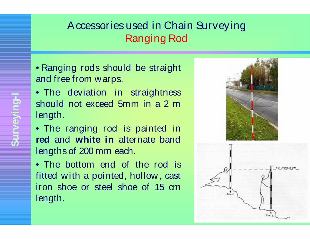
Accessories used in Chain Surveying Ranging Rod
•Ranging rods should be straightand free from warps.
• The deviation in straightnessshould not exceed 5mm in a 2 mlength.
• The ranging rod is painted inred and white in alternate bandlengths of 200 mm each.
• The bottom end of the rod isfitted with a pointed, hollow, castiron shoe or steel shoe of 15 cmlength.

Su
rve
yin
g-I
Accessories used in Chain Surveying Offset Rod
• It is a ranging rod withtwo short, narrow, verticalsighting slots passingthrough the centre of thesection.
• A hook is fitted of agroove is cut at the top toenable pulling or pushingof the chain throughobstruction like hedges.
• Offset rods are meant forsetting outlinesapproximately at rightangles to the main line.
Su
rve
yin
g-I
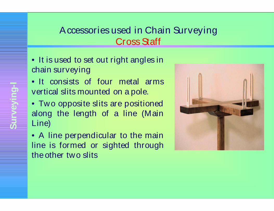
Accessories used in Chain Surveying Cross Staff
• It is used to set out right angles inchain surveying
• It consists of four metal armsvertical slits mounted on a pole.
• Two opposite slits are positionedalong the length of a line (MainLine)
• A line perpendicular to the mainline is formed or sighted throughthe other two slits
Su
rve
yin
g-I
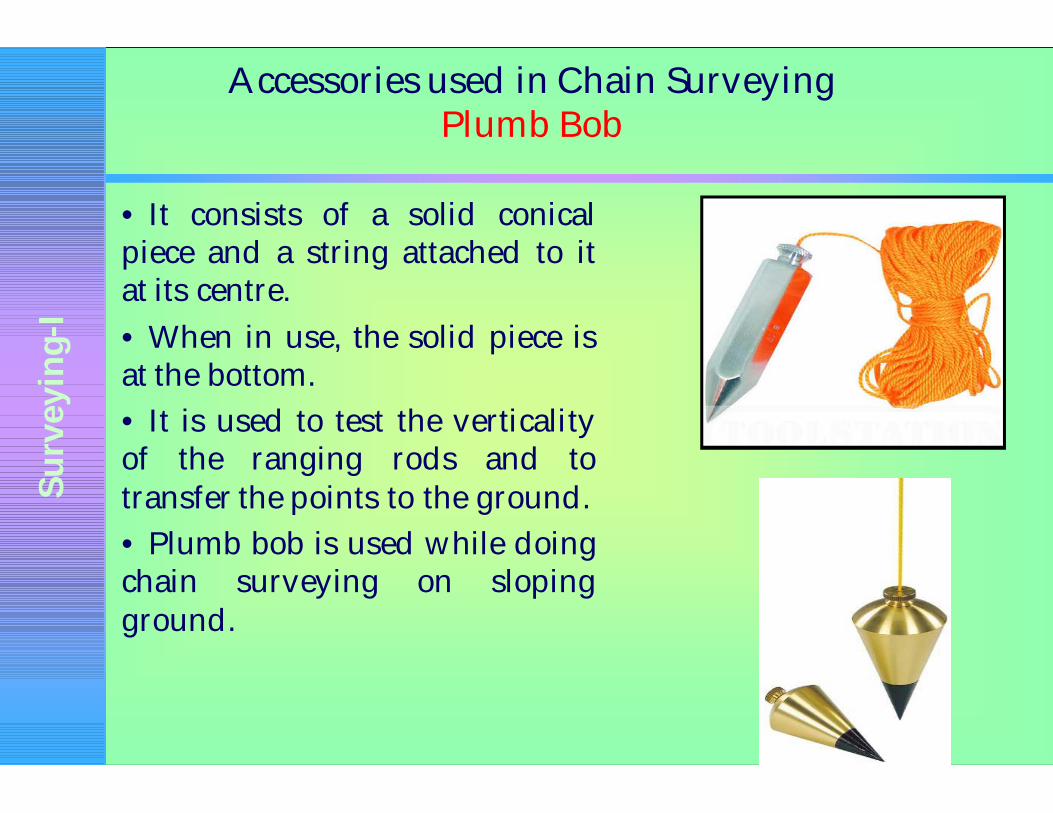
Accessories used in Chain Surveying Plumb Bob
• It consists of a solid conicalpiece and a string attached to itat its centre.
• When in use, the solid piece isat the bottom.
• It is used to test the verticalityof the ranging rods and totransfer the points to the ground.
• Plumb bob is used while doingchain surveying on slopingground.

Su
rve
yin
g-I
Accessories used in Chain Surveying Unfolding and folding of chain
• Both the handles of the chain are held in the left hand and theother portions in the right hand.
• The portion held in the right hand is thrown forward;
• The person throwing moving backward himself.
• The leader takes one handle of the chain and moves forwardhimself.
• The leader takes one handle of the chain and moves forwardtill the chain is stretched to its full length.
• The chain should be free from any kinks or bends.
• After the completion of the work, the two handles are broughttogether and the chain is folded started with the middle pair.
• The links are placed obliquely across each pair.
• The folded chain is securely tied with a rope

Su
rve
yin
g-I
Ranging a line
• It means fixing a series of pegs or other marks suchthat they all lie on a straight line.
• Suppose P and Q are the two ends of a survey line.
• One ranging rod is driven Q.
• The surveyor holds another ranging rod at P andstands at about 30 cm behind ranging rod.
• The assistant goes with another ranging rod alongthe survey line and positions himself approximatelyin line with PQ at a distance less than a chain lengthfrom P.

Su
rve
yin
g-I
Ranging a line
• The surveyor at P keeps his eye in line with PQand signals to the assistant by way of adjustingthe position of the ranging rod held by theassistant traversely.
• This adjustment is continued till the intermediateranging rod is truly in line with P and Q.
• Other intermediate points along the survey lineare also fixed in the same manner.

Su
rve
yin
g-I
Outline of Chain surveying
• A base line which is a chain line is fixed.
• The base line is aligned by ranging.
• The length of the line is measured by chaining.
• For this follower holds the zero end of the chain and the leaderdrags the chain to an intermediate point on the line
• The leader straightens the chain by jerking till the chain liesexactly over the line.
• The leader marks the end of the chain by driving the chain pin(arrow)
• The follower holds the zero end of the chain at the chain pinpoint again
• Thus the chaining is continued till the entire length is covered.

Su
rve
yin
g-I
Outline of Chain surveying
• For locating the details, lateral measurements aretaken to the objects.
• These lateral measurements are called offsets.
• If the offset is at right angles to the base line, it iscalled perpendicular offset.
• If it is inclined to the base line, it is called obliqueoffset.
• Depending upon the situation, perpendicular oroblique offsets are taken
• The length are measured are entered.

Su
rve
yin
g-I
Advantages and disadvantages of chain surveying
Advantages:
•It is simple
• It does not require any costly equipment
• It is adopted for preparing plans for small area
Disadvantages:
• It cannot be used for large areas
• It cannot be used in thick bushy areas with ups and downs.
• Chain surveying is not always accurate.

Su
rve
yin
g-I
Compass Surveying – Prismatic Compass

Su
rve
yin
g-I
Compass Surveying
• Whenever a number of baselines are to be run for obtainingthe details as in traversing, justlinear measurements made bychain surveying will not besufficient.
• The angles included betweenthe adjacent lines should also bemeasured
• Compass is one of theinstruments used to measure theangles.

Su
rve
yin
g-I
Prismatic Compass
Description:
• A magnetic needle is balanced over a pivot in a circular box of 85 mmto 110 mm in diameter.
• A graduated aluminium ring is attached to the magnetic needle.
• An agate cap keeps the aluminium ring stable.
• The box is covered by a glass lid.
• Object vane and eye vane are provided at diametrically oppositeends.
• Eye vane caries a reflecting prism which can be raised or lowered asdesired.
• A vertical horse hair or fine wire is provided at the middle of theobject vane.
• The graduations in the aluminium ring are made in the clockwisedirection starting with 0o at South and 180o at North with invertedmarkings.

Su
rve
yin
g-I
Prismatic Compass
Description:
• A triangular prism fitted below the eye slit enablesmagnification of readings to suit observer’s eye.
• Based on this prism arrangement, the compass is namedprismatic compass.
• Compass is fixed over a tripod with ball and socketarrangement.
• A braked pin is provided below the object vane to damp theoscillations of the magnetic needle while taking readings.
Su
rve
yin
g-I
Prismatic Compass
Working Principle:
• The magnetic field aligns itself with the magnetic meridian (N-S direction)
• The line of sight is actually the line joining the object vane andeye vane
• The angle between the N-S direction and the line of sight isobserved in the compass
• This angle is actually the angle between N-S direction and theline on the ground
• This angle made by the line with the N-S direction is called thebearing of the line.
• Compass is used to measure the bearing of the different linesfrom which the angles included between the adjacent lines arecomputed.

Su
rve
yin
g-I
How to take reading using compass
• The compass is centered over the station by dropping a smallpiece of stone from the centre of the bottom of the compass.
• A plumb bob is used for centering.
• The compass is levelled by adjusting the ball and socket till thetop of the box is horizontal.
• The graduated ring should move freely after having levelledthe instrument.
• Suppose the bearing of a line PQ is to be observed.
• The compass is centered over P.
• It is levelled.
• The prism and the object vane are kept in vertical position.
• The compass is turned slowly till the ranging rod alreadyerected at Q is bisected.

Su
rve
yin
g-I
How to take reading using compass
• In this position, the ranging rod, the object and the eye vaneall lie in the same line.
• The focusing prism is raised or lowered till the readingswere clear and sharp.
• The reading in the ring cut by the object hair line is takenafter damping the oscillations of the ring by pressing thebrake pin.

Su
rve
yin
g-I
Definitions
Magnetic Bearing:
• It is the angle between the magnetic meridian and the line.
• The angle is always measured in the clockwise direction
• It is the direction shown by a freely suspended magneticneedle
• The magnetic meridian is also called bearing.
True Bearing:
• True bearing of a line is the angle between the true meridianand the line.
• The angle is always measured in the anticlockwise direction.
• The true meridian is the line joining the geographical northand south bearings.
Su
rve
yin
g-I
Definitions
Whole Circle Bearing:
• The bearing of lines measured from the North iscalled Whole Circle Bearing.
• The angle is reckoned in the clockwise directionfrom 0o coinciding with the north.
Quadrant Bearing:
• The whole circle is divided into four quadrants.
• The bearing is expressed with N or S as prefix and Eor W as suffix.
• Quadrant Bearing is also known as Reduced Bearing.

Su
rve
yin
g-I
Definitions
Fore Bearing and Back bearing:
• Every line has two bearing namely fore bearing and backbearing
• Fore bearing is the bearing taken in the direction of surveyingand Back bearing is the bearing taken in the reverse direction.
• The difference between the fore bearing and the backbearing should be 180o.
• It means that one or both stations of the line are subjected tolocal attraction.
• Thus, local attraction is the influence caused on the measuredbearings of lines due to the presence of materials like railwaytrack, current carrying wires or cables, etc.,

Su
rve
yin
g-I
To find QB from WCB
N
EW
S
A
35O15’
P
Solution :
Line PA lies in 1st quadrant.
Quadrant Bearing bearing of PA = N 35o 15’ E
Su
rve
yin
g-I
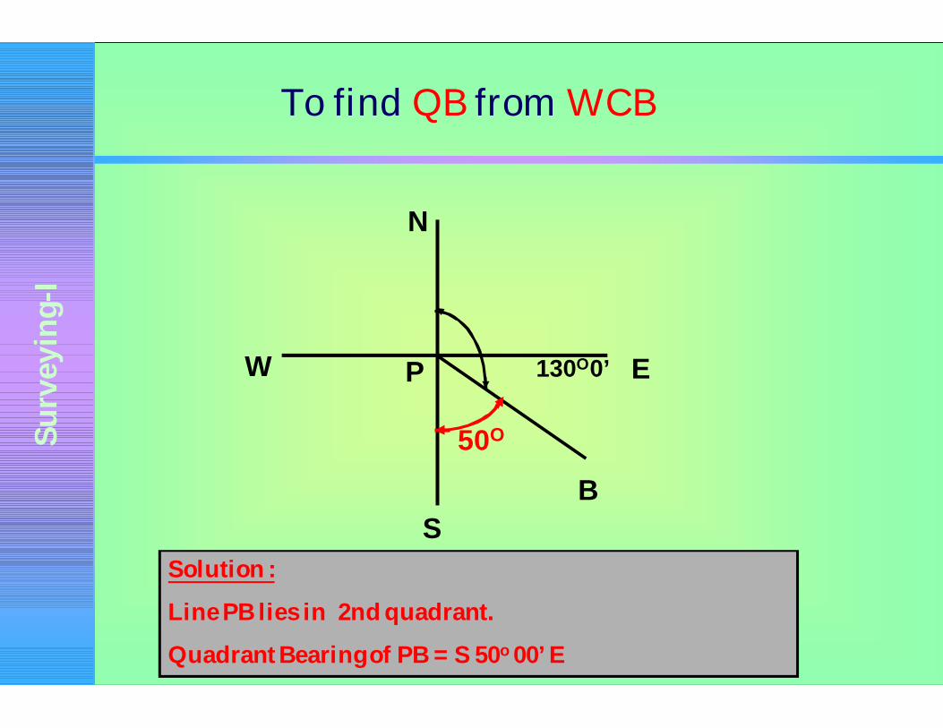
To find QB from WCB
130O0’ E
S
N
W
B
P
50O
Solution :
Line PB lies in 2nd quadrant.
Quadrant Bearing of PB = S 50o 00’ E

Su
rve
yin
g-I
To find QB from WCB
P
210O15’
S
E
N
C
30O15’
Solution :
Line PC lies in 3rd quadrant.
Quadrant Bearing of PC = S 30o 15’ W

Su
rve
yin
g-I
To find QB from WCB
PW
N
S
E
D
69O15’
290O45’
Solution :
Line PD lies in 4th quadrant.
Quadrant Bearing bearing of PD = N 69o 15’ W

Su
rve
yin
g-I
To find Whole Circle Bearing from QB
(i) WCB = PA –N 15o E
(ii) WCB = PB – S 25o 45’ E
(iii) WCB = PC – S 45o 30’ W
(iv) WCB = PD – N 10o W

Su
rve
yin
g-I
To find Whole Circle Bearing from QB
Qn: PA – N 15o E
Ans: Line PA is in the first quadrant. Its WCB is 15o
N
E
S
W
15O
P
A
Su
rve
yin
g-I
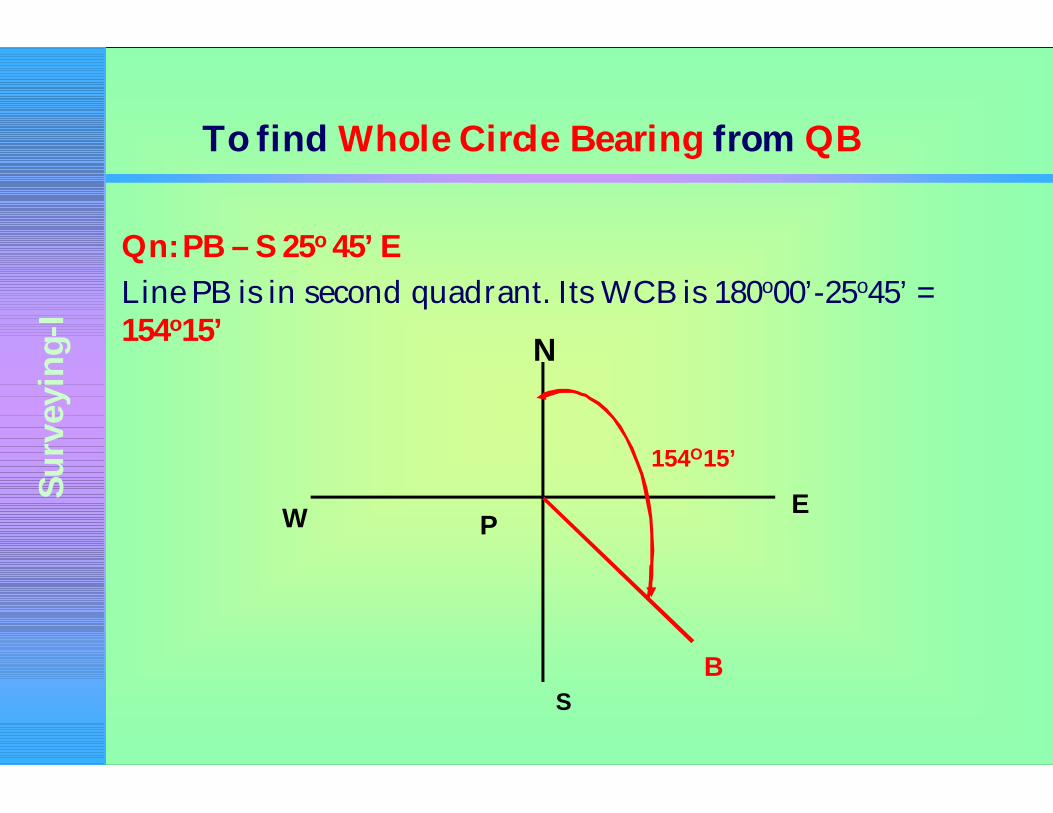
To find Whole Circle Bearing from QB
Qn: PB – S 25o 45’ E
Line PB is in second quadrant. Its WCB is 180o00’-25o45’ = 154o15’
N
E
S
W P
B
154O15’

Su
rve
yin
g-I
To find Whole Circle Bearing from QB
Qn: PC – S 45o 30’W
Line PC is third quadrant. Its WCB is 180o00’+45o30’ = 225o30’
N
E
S
W P
B
225o30’
c

Su
rve
yin
g-I
To find Whole Circle Bearing from QB
Qn: PD – N 10o W
Line PD is in fourth quadrant. Its WCB is
360o00’-10o00’= 350o00’N
E
S
W P
350o00’
D

Su
rve
yin
g-I
To find Back Bearing from Fore Bearing
Qn: Fore bearing of Line PQ is 38o15’, find Back bearing.
Back Bearing =218o15’
38o15’
P
Q
Su
rve
yin
g-I
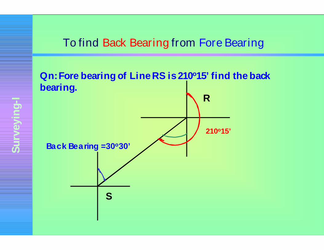
To find Back Bearing from Fore Bearing
Qn: Fore bearing of Line RS is 210o15’ find the back bearing.
210o15’
Back Bearing =30o30’
R
S

Su
rve
yin
g-I
Levelling
•It is a surveying method used to determine the level ofpoints/objects with reference to the selected datum.
•It is also used to set out engineering works.
Uses of Levelling:
• To determine the difference in levels of points/Objects
• To obtain contour map of an area
• To obtain cross section of roads, canals etc.,
• To determine the depth cutting and filling in engineeringworks.
• To establish points or erect machinery or construct a buildingcomponent at a predetermined level.

Su
rve
yin
g-I
Important Terms
Bench Mark: It is surveyor’s mark cut on a stone/ rock or anyreference point used to indicate a level in a levelling survey.
Reduced Level:
•Reduced level of a point is the level of the point with respect tothe level of permanent feature or bench mark.
• It indicates whether the point is above or below the referencepoint (datum).

Su
rve
yin
g-I
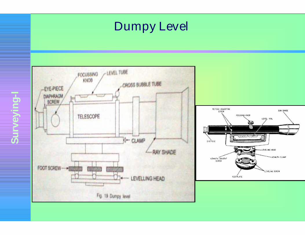
Instruments used in levelling
Instruments used in levelling are,
(i)Levelling instrument
(ii)Levelling staff
Leveling Instrument :
• Simplest form of levelling instrument is dumpy level.
• The different parts of levelling instrument are,
(a) Telescope (b) Eye-piece (c) focusing knob (d) leveltube (e) cross bubble (f) foot screws (g) levellinghead (h) diaphragm (i) ray shade
Su
rve
yin
g-I
Dumpy Level

Su
rve
yin
g-I
Levelling Staff• It is an important accessory used with levelling instrument atthe time of conducting levelling survey.
• Reading is taken on the levelling staff held properly at thepoint concerned by viewing through the telescope of thelevelling instrument.
• Usually 4 m levelling staff may be used of folding type ortelescopic type
• Aluminium levelling staff foldable at every metre length hasalso came to the market.
• The levelling staff consists of three pieces.
• The topmost one slides into the middle one and the middleportion slides into the bottom one.
• When the staff is fully pulled, it will read exactly 40decimeters (4m) from the bottom shoe.
Su
rve
yin
g-I
Levelling Staff
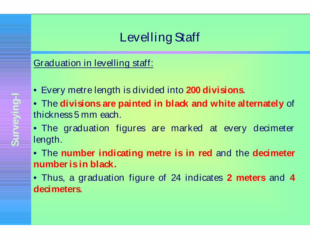
Graduation in levelling staff:
• Every metre length is divided into 200 divisions.
• The divisions are painted in black and white alternately ofthickness 5 mm each.
• The graduation figures are marked at every decimeterlength.
• The number indicating metre is in red and the decimeternumber is in black.
• Thus, a graduation figure of 24 indicates 2 meters and 4decimeters.

Su
rve
yin
g-I
Levelling Staff
Graduation in levelling staff:
•The graduation are made continuously one above the otherin the same line.
• The division lines should be parallel to the base of thebottom shoe and perpendicular to the length of the staff.
• The edges of the division lines should be straight sharplydefined.
• They should be clear and made distinctly visible by properlycontrasting.
• The graduation colour paints used should not crack orblister when exposed to adverse or atmospheric conditions.
Su
rve
yin
g-I
Important Terms in levelling
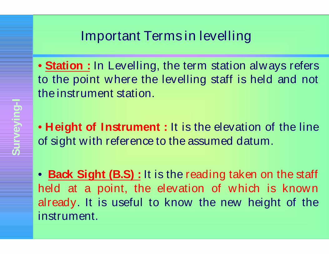
•Station : In Levelling, the term station always refersto the point where the levelling staff is held and notthe instrument station.
•Height of Instrument : It is the elevation of the lineof sight with reference to the assumed datum.
• Back Sight (B.S) : It is the reading taken on the staffheld at a point, the elevation of which is knownalready. It is useful to know the new height of theinstrument.

Su
rve
yin
g-I
Important Terms in levelling
•Foresight (F.S): It is the reading taken on the staffheld at a point of unknown elevation. From, F.S., theheight of the line of instrument above the point can beobtained. It is useful to find the elevation of the point.
•
•Change Point : It is the point at which the fore sightis taken from one instrument station and back sight istaken from the next instrument station.
• Intermediate station : A point between two changepoints is known as intermediate station. Only onereading is taken on the intermediate station.

Su
rve
yin
g-I
Methods of Levelling
•• MethodMethod 11 :: ItIt isis donedone withwith onlyonly oneone settingsetting ofof thetheinstrumentinstrument..
••MethodMethod 22:: WhenWhen thethe twotwo stationstation pointspoints areare widewideapartapart andand thethe instrumentinstrument isis setset upup atat moremore thanthan oneonepointpoint andand thethe levellinglevelling isis carriedcarried outout..

Su
rve
yin
g-I
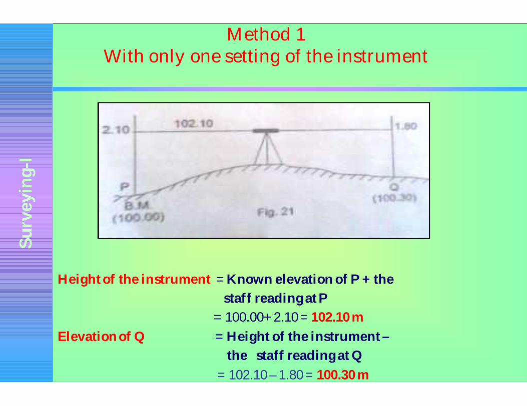
Method 1 With only one setting of the instrument
• The instrument is set up at a point between P and Q and thetemporary adjustments carried out.
• The levelling staff is held at P, the elevation of which is knownalready.
• A back sight is taken on the staff held at P. The staff is thenheld at Q and the foresight is taken.
Su
rve
yin
g-I
Method 1 With only one setting of the instrument
Height of the instrument = Known elevation of P + the
staff reading at P
= 100.00+ 2.10 = 102.10 m
Elevation of Q = Height of the instrument –
the staff reading at Q
= 102.10 – 1.80 = 100.30 m

Su
rve
yin
g-I
Method IIWhen the station points are wide apart, the instrument is setup for
at more than one point and levelling is done(Height of Collimation Method)
•A change point (C.P) is established in between P and Q.
•A back sight is taken at P and a fore sight is taken at the changepoint.
• The instrument is shifted to another point between the changepoint and Q.
• A back sight is taken at the change point and a fore sight istaken at Q.
• Any number of change points are established as required.
• This method is known as Height of Collimation method.

Su
rve
yin
g-I
Method IIWhen the station points are wide apart, the instrument is setup for
at more than one point and levelling is done(Height of Collimation Method)
The elevation of change point = Elevation of P + Back sight at P – Fore
sight at change point (C.P)
= 100.00+1.60-1.10 = 100.50 m
The second height of the instrument = The elevation of change point+
Back Sight at change point
= 100.50+1.25 = 101.75 m
The elevation of Q = The second height of instrument –
foresight at Q
= 101.75 – 1.81 = 99.94 m
Su
rve
yin
g-I
Rise and Fall Method of calculating the level
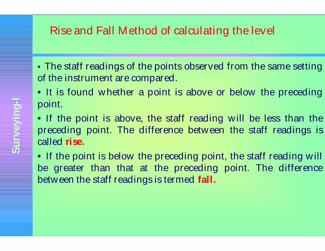
• The staff readings of the points observed from the same settingof the instrument are compared.
• It is found whether a point is above or below the precedingpoint.
• If the point is above, the staff reading will be less than thepreceding point. The difference between the staff readings iscalled rise.
• If the point is below the preceding point, the staff reading willbe greater than that at the preceding point. The differencebetween the staff readings is termed fall.

Su
rve
yin
g-I
Rise and Fall Method
The difference between the staff readings
at P and Q = 2.10 – 1.80 = 0.30 (rise)
Hence, level of Q = Elevation of P + Rise
= 100.00+0.30 = 100.30 m

Su
rve
yin
g-I
Rise and Fall Method
Back sight
Intermediate station
Fore sight Rise Fall Reduced Level
Remarks
1.245 100.00 BM
2.100 0.855 99.145
2.425 0.810 1.290 100.435 STATION A
0.480 1.945 102.380 STATION B
? BS
3.670
? FS
1.290
? RISE
3.235
? FALL
0.855

Su
rve
yin
g-I
Arithmetical Check of Rise and Fall method
3.670 – 1.290 = 3.235 – 0.855 = 102.380 – 100.00
2.380 = 2.380 = 2.380
? B.S - ? F.S = ? Rise - ? Fall = Last R.L – First R.L.
Su
rve
yin
g-I
Fly Levelling
•Any number of change points are established asrequired during levelling. This method is known as flylevelling.
•It is adopted to find the difference in level betweentwo points, when
(i) The two points are too far away
(ii) the difference in level between two points is large
(iii) there are no obstructions in between the twopoints concerned.
Su
rve
yin
g-I
Calculation of Areas
• One of the purposes of surveying is to determine thearea to be surveyed.
• The area of the land obtained by surveying actuallyrefers to the area as projected on a horizontal plane.
• There are different methods of computing the areaof land using the data obtained by surveying.

Su
rve
yin
g-I
Calculation of area by Trapezoidal Rule
• In trapezoidal, a convenient base line is established.
• Perpendicular distances from the base line to theboundary of the land concerned are measured atregular (equal) intervals along the base line.
• These perpendicular distances are called ordinates.
dd dd
h5h4h3h2
1 2 3 4
h1

Su
rve
yin
g-I
Trapezoidal rule
Total Area,
A= d/2 (h1+hn+2(h2+h3+…….+hn-1))

Su
rve
yin
g-I
Simpson's Rule
• This rule is applicable only if the number of ordinates is odd.
A = d/3 (First Ordinate+ Last Ordinate + 2 (sum of odd ordinates)+ 4(sum of even ordinates)
i. e. A = d/3 (h1+hn+ 2(h3+h5+h7+…..+hn-2)+ 4(h2+h4+….+hn-1)
• If the number of ordinates is even, the area of the last trapezoid is calculated separately and added to the result.

Su
rve
yin
g-I
Thanks