i helms data interface
TRANSCRIPT

Pellerin Milnor Corporation
HELMS Data InterfaceBNTUUI02.C01 0000305564 B.2 A.2 8/26/20 9:41 AM Released
This document describes how to connect a Milnor® CBW® tunnel washer to a chemical vendorcontroller with a HELMS data interface in the field.
1. RequirementsBNTUUI02.C02 0000305563 B.2 3/30/21 1:18 PM Released
The interface described in this document requires the following software and hardware:• Mentor® controller software must be version 3.2 or later• Tunnel washer processor board software must be 25704 or later• Milnor® 6-output board solid state (part number 08BN6OBT) must be present in the system
2. WiringBNTUUI02.C03 0000305561 B.2 3/30/21 4:09 PM Released
See schematic W9CBW3NBB in schematic manual ME76CBW3AE for diagrams of the HELMSinterface wiring.Figure 1. HELMS Interface Wiring
LegendA...Milnor® 6-output board (08BN6OAT)B...Milnor® processor boardC... Connection point between the chemical vendor con-
troller and the Milnor® 6-output boardD... Connection point between the Milnor® 6-output board
and the Milnor® processor board
2.1. Connections Between Milnor® Processor Board and 6-outputBoard
BNTUUI02.C04 0000305560 B.2 A.2 8/26/20 9:41 AM Released
• Connect MTA28-4 on the processor board and MTA29-4 on the output board.• Connect MTA28-5 on the processor board and MTA29-5 on the output board.• Connect MTA28-7 on the processor board and MTA29-9 on the output board.• Connect MTA28-8 on the processor board and MTA29-10 on the output board.
IBNTUUI02 / 2021152 BNTUUI02 0000305565 B.2 4/5/21 8:30 AM Released
Pellerin Milnor Corporation
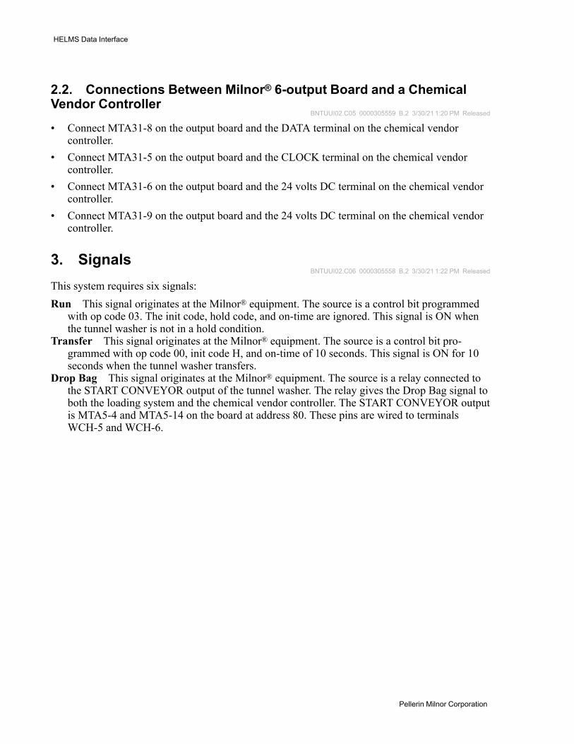
2.2. Connections Between Milnor® 6-output Board and a ChemicalVendor Controller
BNTUUI02.C05 0000305559 B.2 3/30/21 1:20 PM Released
• Connect MTA31-8 on the output board and the DATA terminal on the chemical vendorcontroller.
• Connect MTA31-5 on the output board and the CLOCK terminal on the chemical vendorcontroller.
• Connect MTA31-6 on the output board and the 24 volts DC terminal on the chemical vendorcontroller.
• Connect MTA31-9 on the output board and the 24 volts DC terminal on the chemical vendorcontroller.
3. SignalsBNTUUI02.C06 0000305558 B.2 3/30/21 1:22 PM Released
This system requires six signals:Run This signal originates at the Milnor® equipment. The source is a control bit programmed
with op code 03. The init code, hold code, and on-time are ignored. This signal is ON whenthe tunnel washer is not in a hold condition.
Transfer This signal originates at the Milnor® equipment. The source is a control bit pro-grammed with op code 00, init code H, and on-time of 10 seconds. This signal is ON for 10seconds when the tunnel washer transfers.
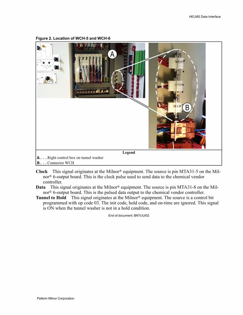
Drop Bag This signal originates at the Milnor® equipment. The source is a relay connected tothe START CONVEYOR output of the tunnel washer. The relay gives the Drop Bag signal toboth the loading system and the chemical vendor controller. The START CONVEYOR outputis MTA5-4 and MTA5-14 on the board at address 80. These pins are wired to terminalsWCH-5 and WCH-6.
HELMS Data Interface
Pellerin Milnor Corporation
Figure 2. Location of WCH-5 and WCH-6
LegendA...Right control box on tunnel washerB...Connector WCH
Clock This signal originates at the Milnor® equipment. The source is pin MTA31-5 on the Mil-nor® 6-output board. This is the clock pulse used to send data to the chemical vendorcontroller.
Data This signal originates at the Milnor® equipment. The source is pin MTA31-8 on the Mil-nor® 6-output board. This is the pulsed data output to the chemical vendor controller.
Tunnel to Hold This signal originates at the Milnor® equipment. The source is a control bitprogrammed with op code 03. The init code, hold code, and on-time are ignored. This signalis ON when the tunnel washer is not in a hold condition.
End of document: BNTUUI02
HELMS Data Interface