i metric i - military standards mil-std, military...
TRANSCRIPT

I METRIC IMIL-T-5624P29 September 1992
SUPERSEDINGMIL-T-5624N10 February 1989
MILITARY SPECIFICATION
TURBINE FUEL A~ON,GRADES JP-4, JP-5, AND JP-!51JI+ ST
Thisspecification is approved for use by all Departments and Agencies of the Department of Defense.
L SCOPE
L1
L2
L3
Scope. This spedcation covers three grades of aviation fuel (see 61).
ClassM!lcation. Atiation turbine fuel shall be of the following grades, as specified (see 6.2).
G~de NATO Code No. Description
Jl?4 F40 Wide cut gasoline me
JP-6 F44 High flashpoint, kerosene type
JP+WP--8 ST SPecial test fiml, high flashpoint,kerosene type, for engine developmentand qualification testing (see 6.1).
References. General references in other documents to turbine fuels in accordance with thisspecificationwithgradenotspecifiedshallbeinterpretedtoalsoincludeturbinelimlsinaccordancewithMIL-T-&3133.
Beneficial comments (recommendations, additions, deletions) and mY ptient data w~amaYbe of use in improving this document should be addressed to ASD/ENES, Wright-PattersonAFBOH 46433-6503 by using the self-addressed Standardization Document Improvement Proposal(DD Form 1426) appearing at the end of this document or by letter.
AMSC IV/A FSC 9130
DISTRIBUTION STATEMENT A Approved for public release distribution is unlimited.
Downloaded from http://www.everyspec.com

MIL-T-56Z4P
2. APPLICABLE DOCUltlf3NTS
2.1 Government documents
2.1.1 Specifications, standards, and handbooks. The following spec~lcations, standards, andhandbooks form a part of this document to the extent specified herein. Unless otherwise specified, theissues of these documents are those listed in the issue of the Department of Defense Index Specifications
and Standards (DODE3S) and supplement thereto, cited in the solicitation (see 6.2).
SPECIFICATIONS
MILITARY
MIL-I-25017MIL-I-27686MIL-T-83133
MIL-I-85470
ST~ARDS
FEDERAL
FED-STD-791
IMILITARY
MIL-STD-290
– Inhibitor, Corrosion/Lubricity Improveq Fuel Soluble (Metric)– Inhibitor, Icing, Fuel System– Turbine Fuels, Aviation, Kerosene ~es, NATO F–34 (JR@ and NATO
F–35– Inhibitor, Icing, Fuel System, High Flash NATO Code Number S-1745
– Lubricants, Liquid Fuels, and Related Products; Methods of ‘I&ting
– Packaging of Petroleum and Related Products
QUALIFIED PRODUCTS LIST
QPL-25017 – Inhibitor, Corrosion/Lubricity Improver, Fuel Soluble (Metric)
(Unless otherwise indicated, copies offederal and military specifications, standards, and handbooks areavailable from the Standardization Documents Order Desk, Bldg4D, 700 Robbins Avenue, PhiladelphiaPA19111–5094.)c., ~
2:2Non-Government publications. The following document(s) form a Partofthisdocumenttotheextent speciiled herein. Unless otherwise spetiled, the issues of the documents which are DoD adoptedare those listed in the issue of the DODISS cited in the solicitation. Unless otherwise specKled, the issuesof documents not listed in the DODISS are the issues of the documents cited in the solicitation (see 6.2).
I2
Downloaded from http://www.everyspec.com

MIL-T-56Z4P
AMERICAN SOCIETY FOR TESTING AND MATERIALS STANDARDS
AS’rNl D86ASTM D93
ASTM D129
ASTM D130
ASTMD166
ASTM D240
ASTM D323
ASTM D381ASTM D446
ASTM D976ASTM D1094
ASTM D1266ASTM D1298
ASTM D1319
ASTM D1322ASTM D1405
ASTM D2276ASTM D2386ASTM D2622
ASTM D2624
ASTM D2887
ASTM D3120
ASTM D3227
ASTM D3!241
ASTM D3242
- Standard ‘I&t Method for Distillation of Petroleum Products– Standard ‘I’M Methods for Flash Point by Pens&-Martens Closed
‘Ibster– Standard W Method for Sulfur in Petroleum Products (General Bomb
Method)- Standard’ibstMethodforDetection ofCopperComosionfiwmPetroleum
Roducts by the Copper Strip ‘Wnish ‘I&t– Standard T&t Method for SayboR Color ofPetroleum Products (Saybolt
Chronometer Method)– Standard “l&t Method for Heat of Combustion of Liquid Hydrocarbon
Fuels by Bomb CalorimeterStandard T&t Method for Vapor Pressure of Petroleum Products (ReidMethod)Standard l%st Method for Existent Gum in Fuels by Jet EvaporationStandard ‘lkst Method for Kinematic Vicosity of ‘IYansparent andOpaque Liquids (and the Calculation of Dynamic Viosi@)Standard ‘I&t Methods for Calculated Cetane Index of Distillate FuelsStandard !Ikst Method for Water Reaction of Aviation FuelsStandard’lhst MethodforSulf%rin Petroleum Products (Lamp Method)Standard Practice for Densi& Relative Densi@ (Specific Gravity), orAPI Gravity of Crude Petroleum and Liquid Petroleum Roducts byHydrometer MethodStandard ‘lkst Method for Hydrocarbon ~es in Liquid Petroleum “Products by Fluorescent Indicator AdsorptionStandard lkst Method for Smoke Point of Aviation Tbrbine FuelsStandard ‘IWt Method for Estimation of Net Heat of Combustion ofAviation FuelsStandard ‘Ikst Method for PartkuIate Contaminant in Aviation FuelStandard lkst Method for Freezing Point of Aviation FuelsStandard lkst Method for Sulfixr in Petroleum Products by X–RaySpectrometry (DoD adopted)Standard ‘I&t Methods for Electrical Conductivi& of Atiation andDistillate Fuels Containing a Static Dissipator AdditiveStandard lkst Method for Boiling Range Distribution of PetroleumFractions by Gas ChromatographyStandard ‘lk.stMethod for ‘IYace Quantities of SuB%r in Light LiquidPetroleum Hydrocarbons by Oxidative MicrocoulometryStandard T&t Method for Memaptan Sulfur in Gasoline, Kerosene,Aviation tibin~ and Distillate Fuels (Potentiometric Method)Standard ‘Ikst Method for Thermal Oxidation Stabili@ of Aviation~bine Fuels (JF’TOT Procedure)Standard ‘lkst Method for Aadity in Aviation ‘Tb.rbineFuel
3
Downloaded from http://www.everyspec.com

MIL-T-5624P
ASTM D3338
ASTM D3343
ASTM D3701
ASTM 1)3703ASTM D3828
ASTM D3948
ASTM D4052
ASTM D4057
ASTM D4176
ASTM D4177
ASTM D4294
ASTM D4306
ASTM D4809
ASTM D4952
ASTM D4953
ASTM D5006
ASTM D5190ASTM D5191ASTM E29
ASTM E380
—
—
—
—
—
—
—
—
—
—
—
—
—
—
—
—
——
—
—
Standaxd T&t Method for Estimation of Net Heat of Combustion ofAviation FuelsStandard lkst Method for Estimation of Hydrogen Content of AviationFuelsStandard ‘It& Method for Hydrogen Content of Aviation l’brbine Fuelsby Low Resolution Nuclear Magnetic Resonance SpectrometryStandard Test Method for Peroxide Number of Atiation !lhrbine FuelsStandard ‘l&t Methods for Flash Point by Setatlash Closed ‘I%ter(DoDadopted)Standard ‘I&t Methods for Determining Water SeparationCharacteristics ofAviation’Ihrbine Fuels by Portable Sepaxometer(DoDadopted)Standard ‘I&t Method for Density and Relative Density of Liquids byDigital Density MeterStandard Practice for Manual Sampling of Petroleum and PetroleumProductsStandard ‘I&t Method for Free Water and Particulate Contamination inDistillate Fuels (Clear and Bright Pass/Fail Procedures)(DoD adopted)Standard Practice for Automatic Sampling of Petroleum and PetroleumProducti (DoD adopted)
Standard ‘I&t Method for Suhr in Petroleum Products byEnergy-Dispersive X-Ray Fluorescence SpectroscopyStandard Practice for Atiation Fuel Sample Containem for !lkstsAHected by Trace ContaminationStandard Test Method for Heat of Combustion of Liquid HydrocarbonFuels by Bomb Calorimeter (Intermediate precision Method)Standard Test Method for Qualitative Analysis for Active Sulfur Speciesin Fuels and Solvents (Doctor ‘l&t)Standard T&t Method for Vapor Pressure of Gasoline and GasolineOxygenate Blends (Dry Method)StandardTbst Method for Measurement of Fuel System Icing Inhibitors(Ether !&pe) in Aviation FuelsVapor Pressure of Petroleum Products (Automatic Method)Vapor Pressure of Petroleum Products (Mini Method)StandardPractice for Using Significant Digits in ‘I&t Data to DetermineConformance .tith SpecificationsStandard I%actice for Use of the International System of Units (S1) (theModernized Metric System)
(Application for copies should be addressed to the American Society for’Ibstingand Materials, 1916 RaceStreet, Philadelphia PA 19013.)
Downloaded from http://www.everyspec.com

MILT-5624P
DEPARTMENT OF TIU.NSPORTATION
TitIe 49 Code of Federal Regulations (CFR) parts 1O(M77
Title 49 CFR Part 173.160 - Exceptions for Class 3 O?lammable and CombustibleLiquids)
Title 49 CFR Part 173.243 – Bulk packaging for certain high hazard liquids and dualhazard liquids which pose a moderate hazard
(Application for copies should be addressed to the Superintendent of Documents, US GovernmentIhinting Oflice, Washington DC 20402.)
OTm-GOVamnent standards and other publications are normally availablefromthe organizations thatprepare or distribute the documents. These documents also maybe available in or through librari- orother informational services.)
2.3 Order of Precedence In the event of a conflict between the text of this document and thereferences cited herein (except for related associated detail specifications, specification sheets, or MSstandards), the text oftbis document takes precedence. l?othingin this documen~ however, supersedesapplicable laws and regulations unless a specific exemption has been obtained.
3. REQUIRRWNH
&l Materials The fuel supplied under this specification shall be refined hydrocarbon distillate fieloils containing additives in accordance with 3.3. The feed stock horn which the fiwl is refined shall becrude oils derived fhm petroleum, tar sands, oil shale or mixtures thereof.
3.2 Chemical and physical requirements. The chemical and physical requirements of the finishedfuel shall conform to those listed in table I or table II, as applicable.
3.3 Additives The type and amount of each additive used shall be reported (see 6.!2).
3.3.1 Antioxidant. Immediately afhrprocessing(i.e.,duringtherundown intofeetiatchtank)andbeforethefimliserposedtotheatmosphere,an approvedantioxidantshallbe addedtoallifl% and
~-6/JP-8 ST fuelsand toW-4 fuelsthatcontainblendingstocksthathavebeenhydrogentreatedto
preventtheformationofgums andperoxidesaftermanufacture.y.’4fielsthatdonotcontainhydrogentreatedblendingstocksmay havetheantioxidantaddedattheoptionofthesupplier.The concentration
ofantioxidanttobe addedshallbe asfollows:
a. For J&6, JP-6/JP-8 ST, and hydrogentreatedJP+k Not lessthqn 17.2mg, normore than
24 mg ofactiveingredientperliteroffiel(6.0to8.4lMLOOO b-).
b. For those JP+ fuels not hydrogen treated, the supplier may (at his option) add not more than24.0 mg of active ingredient per liter of fuel (8.4 lb/1000 barrels).
5
Downloaded from http://www.everyspec.com

I
.. .;:
MIIFT-5624P ~
TABLE I. Chemical and physical requirements and test methods
,Grade Grnde Test Method
Requirements JP-4 J-P-5 ASTM Standards
Color, Saybolt
Ibtal acid number, mg KOHlg, max
Aromatics, vol percent, max
Olefhs, VOIpercent, max
Sulfur, Mercaptan, mass percent, max ORDoctor test
Suli%r,total mass, percent, max
Distillation temperature, deg C!(D28Q7 limits in parentheses) ,Initial boiling point10 percent recovered, max temp20 percent recovered, max temp50 percent recovered, max temp90 percent recovered, max tempEnd point, max tempResidue, vol %, max (for D86)Loss, vol %, max (for D86)
Flash point, deg C (deg F), min
Densityat15°Ckg/L,min (APImax)
kg/L,max (APIrein)
Vapor pressure, 37.8° C (100° F) kPa (psi)minimummaximum
Freezing point, deg C (deg F), max
Viscosity at –20° C, max centistokes
Rpt
0.015
25.0
5.0
0.002Negative
0.40
RptRpt145(130)190(185)245(250)270(320)1.51.5
0.751(57.0)0.802(45.0)
14(2.0)21(3.0)
-58(–72)
Rpt
0.015
25.0
5.0
0.002Negative
0.40
Rpt205(185)RptRptRpt300(330)1.51.5
60(140)
0.788(48.0)0.845(36.0)
46 (-51)
8.5
D156
D3242
D1319
D1319
D3227D4952
D1266, D2622,D129, D3120, or
D4294 11/—
D86 M 111 or.—D2887
D93, orD3828 W—
D1298 or
D4052 Ill—
D323, D4953,
D5190, or
D5191 Ill 12/— —
D2386
D445
Downloaded from http://www.everyspec.com

MIL-T-5624P
TNLJ3 I. Chemical and physical requirements and test methods (Cent’d)
Grade Grade Test MethodRequirements JP4 JP-5 ASTM standards
Heating value,Aniline-gravity product, rein, OR 5,250 4,500 D144)5
Heat of combustion, MY&, (B’NJ/lb), min 42.8 42.6 D3338, D4809, or(18,400) (18,300) D240 2/ U./-—
Calculated Cetane Index Rpt D976 ~
Hydrogen content, mass percent, min OR 13.5 13.4 D3701 4/Smoke poin~ mm, min 20.0 19.0 D1322 -
Copper strip corrosion, 2 hr at
100° C (212° F), m= 1 1 D130
Thermal stabili~Change in pres. drop, mm of Hg, max 26 26 D3241 S/lhbe deposit code, less than 3 3
Existent gum, mgAOO mL, max 7.0 7.0 D381 13/—
Particulate matter, mf& max 1.0 1.0 D2276 W—
Filtration time, minutes, max 10 15 7/ D2276 (Y
Water reaction D1094Interface rating, max lb lb
Water separation index, min 8/ 8/ D3948
Peroxide number, ppm by wt, max — 8.0 D3703
Fuel system icing inhibitor D5006volume percent min 0.10 0.15 9/volume pement max 0.15 0.20 5/
Fuel electrical conductivity, pS/mallowable range 150-600 10/ D2624—
7
Downloaded from http://www.everyspec.com

MI.IFT-5624P
3/—
5/—
6/—
7/—8/—
A condensertemperatureof0°to4°C (32°to40°l?)shaU beusedforthedistillationof$E-5 and
JP-5/JP-8ST fuels.ForJP4, group3 testconditionsshallbeused.
ASTMD3338, for calculating the heat of combustion, is only allowed for use with JP4 fuel. Whenthe fuel distillation testis performed usingASZYkfD2887, the average distillation temperature usedin ASTM.D3338 shall be calculated as follows:
v = (lo% + 50% + 95%)/3
Mid-boiling temperatures may be obtained by either D86 or D2887 to perform the Cetane Indexcalculation. lfD86 values are used, they should be corrected to standard barometric pressure.
ASTMD3343 orASTMD3701 may be used to measure hydrogen content of JP4. When measuringhydrogen content of JP-5 and JJ?-5/JP-8 ST fuel, only ASTM D3701 shall be used.
See 4.5.2.1 for ASTM D3241 testconditionsandtestlimits.
A minimum sample size of one gallon shall be faltered. Filtration time will be determined inaccordance with the procedure in appendix A. The procedure in appendix A may also be used forthe determination of particulate matter as an alternate to ASTM D2276.
The flow reducer ring of appendix ~ 30.c is not required for JP-5 and JP-5/JF8 ST fuel.
The minimum water separation index rating using Micro Separometer rating (MSEP) shall be asfollows:
Product Additives MSEP, rnin
J&4 Antioxidant (AO)*, 85Metal Deactivator (MDA)*, andFuel System Icing Inhibitor (FSII)
JP4 AO*, MDA*, FSII, and 70Corrosion Inhibitor/Lubricity Improver (CI/LI)
JP-5 and AO and MDA* 90
JP-5LII?--6 ST
JP-5 and AO, MDA*, and FSII 85JP-5/JJ+8 ST
JP-5 and AO?,mA*, and CI/LI 80JP-!YJP-8 ST
JP-5 and AO, MDA*, CULI, and FSII 70
JP-5/JP8 ST
* The presence or absence of this additive does not change these limits.
Regardless of which minimum the refiner elects to meet, the refiner shall report the MSEPrating on a laboratory hand blend of the fuel with all additives required by the specification.
Downloaded from http://www.everyspec.com
MIL-T-5624P
9/
10/—
W—12/—
13/—
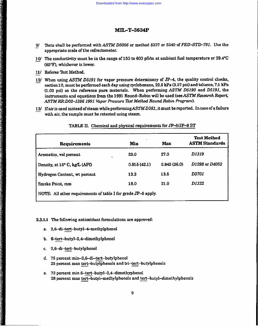
Tests shall be performed with ASTM D5006 or methodappropriate scale of the refractometer.
5327 or5340 of FED-Sl’W791. Use the
The conductivi~ must be in the range of 150 to 600 pS/m at ambient fiel temperature or 29.4°C
(8i5°F),whichever is lower.
Referee ‘Ikst Method.
Wmn using ASllbf D5191 for vapor pressure determinacy of J&t, the quality control checks,section lO, must be performed each day using cyclohexane, 22.5 kpa (3.27 psi) and toluenej 71 kpa(1.03 psi)as the mfereme pure matials. When perfomning ASl!i$f D5190 and D519L theinstruments and equations horn the 1991 Round-Robin will be used (see AS’21kfResemch ReportjASTMlUkD02-1286 1991 Vapor Pressure W Method Round Robin Pm?nd.
Ifairis used instead ofsteam while perfonningASTMD381, it must be reported. In case of afaihxewith air, the sample must be retested using steam.
TMLE It. Chemical and physical requirements for JPWJP-8 ST
Test Method
Requirements Min’ ASTM standards
Aromatics, vol pement 23.0 27.0 D1319
Density, at 15° C, l@L (API) o.816 (42.1) 0.846 (36.0) D1298 or D4052
Hydrogen Content wt percent 13.3 13.6 D3701
Smoke Point mm 18.0 21.0 D1322
NOTE: All other requirements of table I for grade JP-6 apply.
3.3.Ll The following antioxidant formulations are approved:
a. 2,6-di-tert-buty14-methylphenol
b. 6-tert-butyl-2,&&nethylphenol
c. 2,6-&tert -butylphenol
d. 75 percent min-2,8-di-tert-butylphenol25 percent max text-bu~henols and tri-tert-butylphenols
e. 72 percent min 6-tert-but@-2,4+imethyphenol28 percent max t~~butyl-methylphenols and tert-butyl-dimethylphenols
9
Downloaded from http://www.everyspec.com

MI.L-T-5624P
3.3.2 Metal deactivator. A metal deactivator, N,N’-disali@dene-l,2-propanediamine orN,N’-disalicylidenel ,2-cyclohexanediamine may be blended into the fuel in an amount not to exceed5.8 mg active ingredient per liter of fuel (2 lb/1000 barrels or 22 m~gal (US)). Met~ deactivator additiveshall not be used in JP-5 or JP-4 unless supplier has obtained written consent horn procuring activity.
3.3.3 Corrosion ifilbitor. A corrosion inhibitorconforming toM1.-I-25Ol 7shall be blended into the
JP-4, JP-5, and Jl?-5/JP-8 ST fuel by the supplier. The amount added shall be equal to or greater thanthe minimum effective concentration and shall not exceed the maximum allowable concentration listedin the latest revision of QPL–250J 7. The supplier or transporting agency, or both, shall maintain andupon request shall make available to the Government evidence that the corrosion inhibitors used areequal in every respect to the qualii3cation products listedinQPL-25017.
3.3.4 Fuel system icing inhibitor. The use of a fuel system icing inhibitor shall be mandatoxy. ForJP4 the icing inhibitor shall be in accordance with MIL–I–27686 or MI~I-8547@ for JP-5 andJP-5/JP-8 ST fuel the icing inhibitor shall be in accordance with MIL-I-85470. The point of injectionof the additive for JP4, JP-5, and JP-5/JP-8 ST, and the type of additive for JP4 shall be determinedby agreement between the purchase authority and the supplier.
3.3.4.1 JP4withfuel system icing inhibitor in accordance withMIL-I-27686 should not be mixed withJP4withfuel system icinginhibitorin accordance withMIL-R35470. Mixing them will cause problemsduring the.determination, using the refr~ctometer, of volume percent of icing inhibitor in the fuel.
3.3.5Static dissipator additive. A static dissipator additive shall be added toJP4fuels in .mf35cientconcentration to increase the conductivity of the fuel to within the range specified in table I, at the pointof injection. The point of injection shall be determined by agreement between the purchasing authorityand the supplier. The following static dissipator additive is approved Stadis 450 marketed by E. I.dupont de Nemours Co., Wilmington DE.
3.3.6 Premixing of additives. Additives shall not be premixed with other additives before injectioninto the fuel so as to prevent possible reactions among the concentrated forms of diiTerentadditives.
3.4 Workmanship. At the time of Government acceptance, the finished fuel shall be visually free fromundissolved water, sediment, or suspended matter and shall be clear and bright. In case of dispute, thefuel shall be clear and bright at 21° C (70° F). If the finished fuel is not visually free horn sediment orsuspended matter but meets the Table I particulate matter content of 1.0 mg/L max, the fuel shall be,.s.considered to have met this workmanship requirement.
..
~4. QUALITY ASSURANCE PROVISIONS
1 4.1 Responsibility for inspection. Unless otherwise specfiled in the contractor pumhase order, thecontractor is responsible for the performance of dl inspection requirements (examinations and tests) asspecified herein. Except as otherwise specified in the contractor purchase order, the contractor may usehis own or any other facilities suitable for the performance of the inspection requirements speci.tied
10
Downloaded from http://www.everyspec.com

MIbT-5624P
h- unless disapproved by the Government. The Government resmes the right to perform any ofthe inspections set forth in the specification where su& inspections are deemed necessary to ensuresupplies and se.mites conform to prescribed requirements.
&Id Respomdbilityi’or compliance. All items shall meet all mquirementa of sections 3 and 5. ‘I%einspection set forth in this specification shall become a part of the contractor’s overall inspection systemor quality program. The absence of any inspection requirements in the specification shall not relieve thecontractor of the responsibility of ensuring that all products or supplies submitted to the Governmentfor acceptance comply with all requirements of the contract. Sampling inspection, as part ofmanufacturing operations, is an acceptable practice to ascertain conformance to requirements, however,this does not authorize submission of known defective material, either indicated or actual, nor does itcommit the Government to accept defbctive materiaL
42 Classification of inspections. The inspection requirements specified herein are classified asquality confoxmanm inspection (see 4.4).
4.3 Inspection conditions Requirements contained in table I and table II are absolute, as definedin ASTMl?29, and shall not be subject to correction for test tolerances. If multiple determinations aremade, results falling within any specified repeatability and reproducibility tolerances may be averaged.For rounding off of significant figures, AiM!ME29 shall apply to all tests required by this specification.
4.4 Quality conformance inspections. Inspection shall be performed in accordance with method9601 ofl?ED-sTD-791.
4.4.1 Inspection lot. For acceptance purposes, individual lots shall be examined as specified hereinand subjected to tests for all requirements cited in section 3.
A4.L1 Bulldot. Abulklot shall consist of an indefinite quantity of a homogeneous mixture ofmaterialoffered for acceptance in a single isolated container.
4.4.X2Packaged lot. A packaged lot shall consist of an indefinite number of 208-liter (W-gallon)drums or smaller unit packages of identical size and shape offered for acceptance and filled ikom theisolated tank containing a homogeneous mixture of mattial.
4.4.2 ~phg phns .-
4.4.2LlSampling forverii5cationofproduct quality.Each bulkorpackagedlotofmaterialshall
be sampledforverificationofproductqualityinaccordancewithASTM D4057 and/orASZI14D4177,except where individual test procedures contain specific sampling instructions.
4.4.2.LI A number of jetfuelproperties are very sensitive to trace contamination which can originatefrom sample containers. For recommended sample containers refer to ASTM D4306.
11
Downloaded from http://www.everyspec.com
MIL-T-5624P
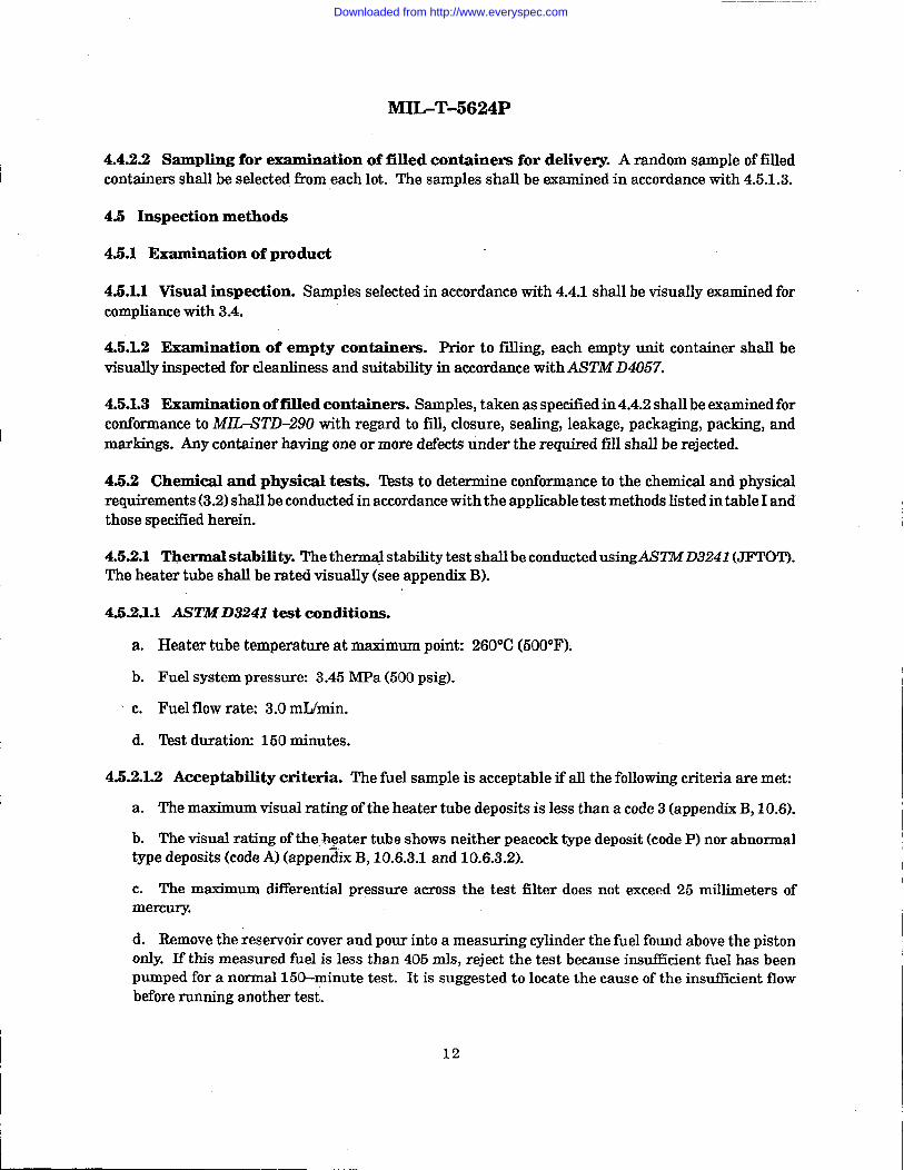
4.4.2.2 Sampling for exarnination of filled containers for delivery. A random sample of fdledcontainers shall be selected from each lot. The samples shall be examined in accordance with 4.5.1.3.
4.5 Inspection methods
4.5.1 Examination of product
4.5.1.1 Viiual inspection. Samples selectedinaccordancewith4.4.1shallbevisuallyexaminedfor
compliancewith3.4.
4.5.1.2 Examination of empty containem. Priortofilling,each empty unitcontainershallbe
visuallyinspectedforcleanlinessand suitabilityinaccordancewithASTM D4057.
4.5.L3 Examination of filled containers. Samples,takenasspecifiedin4.4.2shallbeexaminedfor
conformancetoMIZ+-STD-290 withregardtofill,closure,sealing,leakage,packaging,packing,and
markings.Any containerhavingoneormore defectsundertherequiredffllshallberejected.
4.5.2 Chemical and physical tests. ‘1’kststo determine conformance to the chemical and physicalrequirements (3.2) shall be conducted in accordance with the applicable test methods listed in table I andthose specified herein.
4.5.2.1~ermalstability. The therm@ stabilitytestshallbeconductedusingASZZ14113241(JFTOT).
The heater tube shall berated visually (see appendix B).
4.5.2.1.1 AST.M D3241 test conditions.
a. Heater tube temperature at maximum point: 260”C (500°F).
b. Fuel system pressure: 3.45 MPa (500 psig).
~ c. Fuel flow rate: 3.0 mIJmin.
d. ‘I&t duration 150 minutes.
4.5.2.12 Acceptability criteria. The fuel sample is acceptable if all the following criteria are met:
a. The maximum visual rating of the heater tube deposits is less than a code 3 (appendix B, 10.6).
b. The visual rating of the:heater tube shows neither peacock type deposit (code P) nor abnormaltype deposits (code A) (appendix B, 10.6.3.1 and 10.6.3.2).
c. The maximum diHerential pressure across the test filter does not exceed 25 millimeters ofmercury.
d. Remove the reservoir cover and pour into a measuring cylinder the fuel found above the pistononly. If this measured fuel is less than 405 mls, reject the test because insu.tlkient fuel has beenpumped for a normal 150-minute test. It is suggested to locate the cause of the insuftkient flowbefore running another test.
12
Downloaded from http://www.everyspec.com

lk’nbT-56z4P
4.5.ZL3 AM’MD3241 reported data
a Differential pressure in millimeters ofmercuxyat160 minutes,ortimetodeferentialpressure
of25 millimetersofmerctuy,whichevercomesfirst.
b. Heat tube deposit code rating at the end of the test.
c. If a Mark 8A tube deposit rater is available, the maximum SPUN TDR rating shall be reportedfor information purposes.
4.6 Test report ‘I&X data required by 4.5.2 shall be reported in the same order as listed in table I,unless directed otherwise by the procuin g activity.
5. PACKAGING
5.1 Packaging, packing, and marking. Packaging, packing, and marking shall be in accordancewith MZL-STD-Z90. All fiel containers shall be marked with the flashpoint obtained in 4-52 in bothdegrees F and degrees C of the fuel contained therein. For JP4,aflashpointof-29°C(-20”F)maybeassumed.
52 ‘1’kansportation of fiels. The transportation of the JP4, J&6, and JP-6/JP-6 ST fimls shall bein accorckuicewith the Department of !hnsportation Rules and Regulations listed in 2.2.
6. NOTES
(m section contains information of a general or explanatory nature that may be helpfbl, but is notxYlandatoIy.)
6J Intended use. TheJP4 andJP6 I&Is covered by this specification areintendedforusein airuaftturbine engines. The JP-6/JP-8 ST(special test) fiw.1is a worst-case kerosene type aviation turbinefi.mlin terms of fiel efkcts on engine starting, altitude relight, combustor durability, end exhaust smokeemissions. This fuel is intended for use in the development, testing, and qualification of enginecomponents, engines, and akcraft. When authorized, the JP+/JP-6 ST fiel may also be used forqualification testing of ground-based turbine and diesel engines.
6.2 Acquisition requirements. Acquisition documpnts must specify the following
a. Title, number, and date of this specification.
b. Issue of DODISS to be cited in the solicitation, and if required, the specific issue of individualdocuments referenced (see 2).
c. Grade of fiel required (see 1.2).
d. Quantity required and size containers desired.
13
Downloaded from http://www.everyspec.com

e. Level of packaging and packing required (see 5.1).
f. Location and injection method for addition of fiel system icing inhibitor (JP-4, J&5, andJP-5/JP-6 ST and electrical conductivity additive (JP4 ordy).
6.3 International agreements. Certain provisions of this specification are the subject ofinternational standardization agreement ASCC.Air Standard 15/6, ASCCAdvisory Publication 15/9,STANAG 1135 and STANAG3747. When amendment, revision,orcancellationofthisspecificationis
proposedwhichtiectsorviolatestheInternationalagreementconcerned,thepreparingactivityshall
take appropriatereconciliationactionthrough internationalstandardizationchannelsincluding
departmentalstandardizationoffice,ifrequired.
6.4 Subject term (key word) listing
AntioxidantAviationturbinefuelCorrosioninhibitorFuelIcing inhibitorJet fuelJI?-4JP-5J-P-8Special test fuelStatic dissipator additive‘Ihrbine
6.5 Units of measure have been converted to the International System of Units (Metric) in accordancewith ASl!M E380.
6.6 Grade JP-6 fuel. Characteristics of JI-8 fuel (such as density, distillation temperatures, etcetera) are very similar to those of JP-5. Materials and accessories suitable for use withJP4, JP-5, andJP-5/JP-8 ST fuel are also suitable for use with JP-6.
6.7 Changes from previous issue. Marginal notations are not used in this revision to identi&changes with respect to the previous issue due to the extensiveness of the changes.
. Custodian: Preparing activity:Army-ME Air Force – 11Navy – ASAir Force – 11
DLA – PS
IReviewactivities:
Army -A~ARAir Force – 68
14
Project No. 9130-0161
Downloaded from http://www.everyspec.com

lvlIhT-56z4P
APPENDIX A
METHODS FOR DETERMINATION OFFILTRATION TIME AND TOTAL SOLIDS (PARTICULATE)
10. Scope. This method describes a procedure for determining singularly or simultaneously thefilterabili& characteristics and solids contamination of jet fiel. The purpose is to detect and preventcontaminantts in jet fuel which can plug and cause zupture of ground filtration equipmen~ therebyaffecting flight reliabilityhfety of aimraft
24). S~y of’methods. 3.79 liters (one gallon) of jet fiel is filtered through a membrane i51terinthe laboratory. The time required to filter this volume is measured in minutes and solids content isdetermined gravimetncally.
30. Apparatus
a. Membrane filtec White, plain 47 mm diameter, nominal pore size 0.8 micron. The membranemust be approved by ASTM for use withAS7M D2276.
b. Filtration apparatus: Of the types shown inAlX7’MD2276, figure A3. It consists of afhnnel andfunnel base with a filter support such that a membrane filter can be securely locked or clampedbetwe& the sealing surfaces of the ‘iiumel and its base. The fbnnel and funnel base shall be ofstainless steel or glass construction.
c. Insert ring The insert ring shall only be used with JP4 fuel.A 47–mm diameter paper flowreducer ring with dimensions to give i51teringarea of 4.8 cm2. (Millipore Corporation Part No. XXIO047 lo.)
d.
e.
f.
g.
h.
Vacuum flask A minimum of 4liters.
Vacuum system: That develops in excess of 67.6 kpa (20 inches of mercury) vacuum.
Ove.m Of the static @e (without fa assisted circulation) controlling to 90° i 6°C (194° t 9°F).
Forceps: Flat-bladed with underrated nonpointed tips.
SoIvent filtering dispenser Containing a 0.45 micron maximum pore size filter in the delivexyliue. . .
i. Glass petri dish Approximately 125 mm in diameter with removable cover.
j. Analytical balance: Single or double pan, the precision standard deviation of which must be0.07 mg or better.
40. Preparation of apparatus and sample containers. AUcomponents of the filtration apparatus(except the vacuum flask), sample containers and their caps must be cleaned as described in A2.6.1.1
15
Downloaded from http://www.everyspec.com

MIL-T-5624P
throughA2.6.1.7ofA%!’J4112276.Allmetalpartsofthefiltrationapparatusaretobeelectricallybondedandgrounded,includingthefuelsamplecontainerandthemetalinsertring,ifused.SeeASZ’iWD2276forothersafetyprecautions.
50. Sampling. Obtain a representative one gallon sample as directed inA2.7 ofA5’Z’..D2276. Whensampling from a flowing stream is not possible, an all level sample or an average sample, in accordancewithASTM D4057 ancVorASTM D4177 shall be permitted. The on=gallon sample container shall bean interior epoxy~oated metal can, a brown glass bottle, or a clear glass bottle protected by suitablemeans from exposure to light.
60. Test procedure
a. Membrane filters shall be removed from the package and placed in an oven for a minimum of
15 minutes at 90°C. After preheating, but prior to weighing, the membrane filters shall be storedin a desiccator.
b. Each membrane filter shall be weighed. A filter weighing in excess of 90 mg will not be used inthe test.
c. The insert ring shall be centered on the fdterbase. The membrane filter shall be placed directlyover the insert ring. The top funnel shall be locked into place.
d. Immediatelypnor to filtering the fuel, shake the sample to obtain a homogeneousmix and assurethat fuel temperature does not exceed 30°C (86”F). Clean the exterior or top portion of the samplecontainer to insure that no contaminants are introduced. Any fme water present in the fiel samplewill invalidate the filtration time results by giving an excessive fdtration time rating.
e. With the vacuum off, pour approximately 200 ml of fuel into the funnel.
f. b vacuum on and record starting time. Continue fdtration of the 3.79 liters (one gallon)sample, periodically shaking the sample container to maintain a homogeneousmix. Record thevacuum in kl?a (inches of mercury) one minute after start and again immediately prior to completionof filtration. Throughout fdtration, maintairi a suf15cientquantity of fuel in the funnel so that themembrane falteris always covered.
g. Report the filtration time in minutes expressed to the nearest whole number. Infiltration of the3.79 liters (one gallon) is not completed within 30 minutes, the test will be stopped and the volumeof the fuel falteredwill be me-asured. In these cases, results will be reported as 30+minutes/volumeof fuel filtered.
h. Reportthevacuum inkPa (inchesofmercury)as determinedfrom the averageofthetwo
readingstakenin60.f.
i. After recording the filtration time, shut off the vacuum and rinse the sample container withapproximately 100 ml of filtered petroleum ether and dispense into the filtration fmnel. Turn thevacuum on and filter the 100 ml rinse. Turn vacuum off and wash the inside of the funnel with
16
Downloaded from http://www.everyspec.com

MJLT-5624P
approximately 50 ml offiltered petroleum ether. !Ihrn vacuum on and filter. Repeat the funnel rinsewith another 50 ml of petroleum ether but allow the rinse to soak the filter for approximately30 seconds before turning the vacuum on to filter the rinse. With vacuum on, carefully remove thetop fimnel and rinse the periphery of the membrane filter by directing a gentle stream of petroleumether horn the solvent dispenser from the edge of the membrane toward the center, taking care notto wash contaminants off the filter. Maintain vacuum after final rinse for a few seconds to removethe excess petroleum ether from the filter.
j. Usingforceps, canfdlyremovethe membranefikerfromthefilterbase andplaceinacleanPetxi
dish. Dry in the oven at 90°C (194°F) for 16 minutes with the cover on the Petri dish slightly ajar.Place dish in a dessicator and allow to cool for a minimum of 15 minutes. If more than one sampleis processed, cooling time will have to be increased. Reweigh the filter.
k. Report the total solids content in m#liter by using the following formula
Weight gain of filter in mgs= [email protected]
3.785
1. Should the sample =ceed the 30-minute filtration time and a portion of the fuel is not filtered,the solids content in m#Mer will be figured as follows: Determine the volume of fuel fltered bysubtracting the ml of fhel remaining from 3785.
Weight gain of f51ter in mgs
ml of fuel filtered X 0.001= m@ter
70. Test limits.
a. FiMration time
(1) me m-- allowable ~tration time shall be 10 minutes for grade JI% and 15 minutesfor grade J&5.
(2) ‘l’he vacuum should =ceed 67.5 I@a (20 inches of memry) throughout the test (i.e., thedifkrential pressure across the filter should exceed 67.5 kpa (20 inches of memury)).
(3) ‘l”he fbd temperature shall be between 18; and 30°C (64° and 86”F).
b. ‘Ibtal solids: Maximum allowable particulate matter is 1.0 m@liter.
80. Notes.
80.1Ifitisdesiredtodeterminethefiltrationtimeandnotthetotalsolidscontent,performthetestbyomittingsteps60.i,60.j,60.k,and60.1.
17
Downloaded from http://www.everyspec.com

...
MIbT-5624P
80.2 If it is desired to determine the total solids content and not the filtration time, use of the insertring may be omitted. It is also permissible, but not required, to use a control filter for a specific analysisor a series of analyses. When this is accomplished, the procedures specified in A.2 ofASTMD2276 apply.
... .
18
Downloaded from http://www.everyspec.com
MILT-5624P
APPENDIX B..
HEATER TUBE DEPOSIT RATING
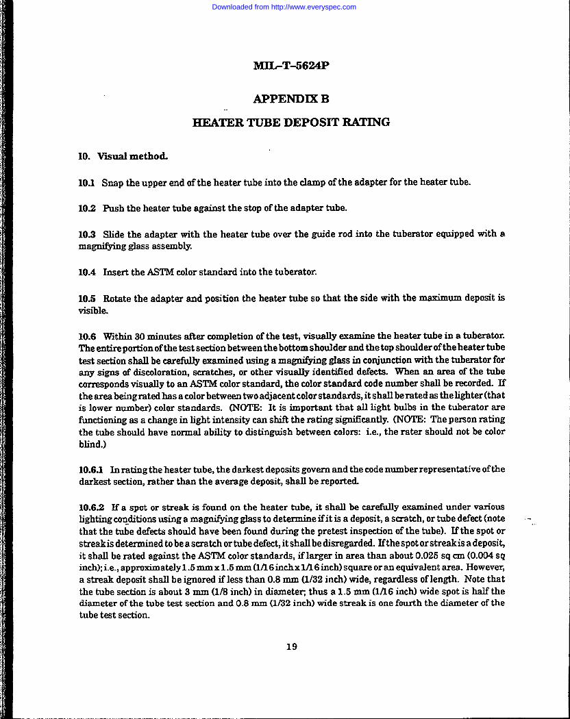
10. Viual method.
10.1 Smp the upper end of the heater tube into the clamp of the adapter for the heater tube.
10J2 Push the heater tube against the stop of the adapter tube.
10J3 Slide the adapter with the heater tube over the guide rod into the tuberator equipped with amagnifying glass assembly.
10.4 Insertthe ASTM color standard into the tuberator.
10.5 Rotate the adapter and position the heater tube so that the side with the maximum deposit isvisible.
10.6 Within 30 minutes after completion of the testj visually examine the heater tube in a tuberator.The entire portion ofthetest section between the bottom shoulder and the top shoulderoftheheater tubetest section shall be carefully examined using a magni&ing glass in conjunction with the tuberator forany signs of discoloration, scratches, or other visually identified defects. When an area of the tubecorresponds visually to an ASTM color standard, the color standard code number shall be recorded. Iftheareabeingrated has acolorbetween two adjacent colorstandards,it shall berated as thelighter(thatis lower number) color standards. (NOTE: It is important that all light bulbs in the tuberator arefb.nctioning as a change in light intensity can shift the rating significantly. (NOTE: The pemon ratingthe tube should have normal abili~ to distinguish between colors: i.e., the rater should not be colorblind.)
10.6J Inratingtheheater tube, the darkest deposits govern and the code number representative of thedarkest section, rather than the average deposit, shall be reported.
10.6.2 If’a spot or streak is found on the heater tube, it shall be carefully examined under variousbghtingco@tions using a magni@ing glass to determine ifit is a deposit, a scratch, or tube defect (note -that the tube defects should have been found during the pretest impection of the tube). U the spot or -streakis determined to be a scratch or tube dekt, it shdlbe disregarded. Ifthespot orstreakis a deposit,it shall be rated against the ASTM color standards, if larger in area than about 0.025 sq cm (0.004 sqinch); i.e., approximately 1.6 mm x 1.5 mm (1A6 inchx Ul 6 inch) square or an equivalent area. However,a streak deposit shall be ignored if less than 0.8 mm (1/32 inch) wide, regardless of length. Note thatthe tube section is about 3 mm (1/8 inch) in diameti, thus a 1.6 mm (1/16 inch) wide spot is half thediameter of the tube test section and 0.8 mm (1)32 inch) wide streak is one fourth the diameter of thetube test section.
19
Downloaded from http://www.everyspec.com
MIbT-5624P
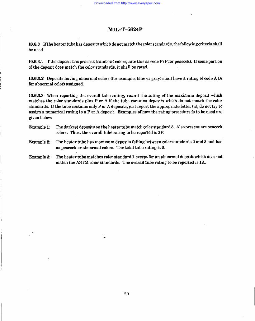
10.6.3 Iftheheatertubehasdepositswhichdonotmatchthecolorstandards,thefollowingcriteriashallbeused.
10.6.3.1 Ifthedeposit has peacock (rainbow) colors, rate this as code P (P for peacock). If some portionof the deposit does match the color standards, it shall be rated.
10.W3.2 Deposits having abnormal colors (for example, blue or gray) shall have a rating of code A (Afor abnormal color) assigned.
10.6.3.3 When reporting the overall tube rating, record the rating of the maximum deposit whichmatches the color standards plus P or A if the tube contains deposits which do not match the colorstandards. If the tube contains only P or A deposits, just report the appropriate letter (a} do not try toassign a numerical rating to a P or A deposit. Examples of how the rating procedure is to be used aregiven below
Example 1: The darkest deposits on the heater tube match color standard 3. Also present are peacockcolors. Thus, the overrdl tube rating to be reported is 3P.
Example 2: The heater tube has maximum deposits falling between color standards 2 and 3 and hasno peacock or abnormal colors. The total tube rating is 2.
Example 3: The heater tube matches color standard 1 except for an abnormal deposit which does notmatch the ASTM color standards. The overall tube rating to be reported is 1A.
.-
20
I
Downloaded from http://www.everyspec.com

STANDARDIZATION DOCUMENT IMPROVEMENT PROPOSAL
lIWTRUCHONS
1.The preparingactivity must complete blocks 1, 2, 3, and 8. In block 1, both the document number and revisionlettershouldbe given.
2. The submitterof this form mustcompleteblocks4,5,6, and 7.
3. The preparingactivitymust providea replywithin30 days from receiptof the form.
NOTE This formmay not be used to requestcopies of documents,not to requestwaivers,or clarificationof requirementson currentcontracts.Commentssubmittedonthisformdonotconstituteorimplyauthorizationtowaiveanyportionofthereferemeddocumnt(s)or to amendcontractual requirements.
2 DOCUMENT DKJli (YYMff)Ll)
:...:.>.... . .... ..
3. DocuMENTT’frLE
TUPMNE PUEL, AVIXI’ION,GIULDESJP-4, JP-5,m“Jp-5/Jp-8 ST
4. NAIURE OF CHANGE (Idetttifypamgraph nwnberami incfudeproposed rewrife, ~passtile. Attach ex&asheets as needed.)
5. REASON FORRECQMMENDAITON
@:*M...:..:.j. . , ..::::::...!”::..::,:. ::. . ,’ . “;:’:’,,’:. .::!: .,.’:,i;..:>:.,..:.-...,:...:.:. :.. ..:. ..
..: .,.,..............
!S<i+%!%%?++a?odj): :.‘j i..;‘:~ :; :;..........;.....;y,:,:::.,...y,., ,:. . :,::. :.. :: .:,..:;+::-:,;:y<;?‘:,.$: ;: ‘,.,......:,,.,,.....,.,...........,.,,,.,,.L,:f.1.,w+~,:,..t,:,.>: ,,,..,:.:,.:+,.::,.;::.,.,:::.,,. .<,:.:,*y.,:,,,:,,,,.: :, ,............... . ,,. .,. : “: .::.,:,,.,.,>.:..*.,.:...;:.,: :,,.;: i..:..: >.;,:;,,2:::,!,:$:.;:;,....:. : .. :., .;. , ,:,:::...?$....-s:...,.:.,.. ;: .,,
8. PRFPARINGACITVTTY
AN&M+fE B.TELEPHONE(IncludeAreaCode)
AFCODE1l(1)~ o)AUTOVON(Inapplicable)
(513)255-6281 DSN 785-6281
c ADDRESS{lnchakZipCade) IFYOU DON~ RJZCHVEAREPI.YWTITUN45DAYS,CONIX~
ASDIENES DofmseQua@aid StsndwdiauiaaOfiicaS203kabq Pike+SuiteI1LW3,FallsChurd VA22041-34dd
WRIGHT-PATI’ERSONAFB OH 45433-6503 ‘Rikphato(703)7564340 AUTOVON 2S9-2340———. . . . . —-..LJIJ ~-OIIIJ 1426, WC-I 13Y Pr8vious Cditias am abmlaa L98129U
Downloaded from http://www.everyspec.com