i report collection la-5284-pr copy -- 9 · i la-5284-pr clc-l 4 report collection m%wkxnjct1on...
TRANSCRIPT

I
LA-5284-PRClC-l 4 REPORT COLLECTION
m%wKxNJcT1oN
PROGRESS REPORT COPY
9--
c●
I
;
(10s(
Quarterly Report
Advanced Plutonium Fuels Program
January 1 to March 31, 1973
I
)
1)alamosscientific Laboratory
of the University of CaliforniaLOS ALAMOS, NEW MEXICO 87544
UNITED STATESATOMIC ENERGY COMMISSION
CONTRACT W-7405-ENG. 36

This report was prepared as an account of work sponsored by the United
States Government. Neither the United States nor the United States Atomic
Energy Commission, nor any of their employees, nor any of their contrac.
tors, subcontractors, or their employees, makes any warranty, express or im-
plied, or assumes any legal liability or responsibility for the accuracy, com-
pleteness or usefulness of any information, apparatus, product or process dis-
closed, or represents that its use would not infringe privately owned rights.
This rewrt presents the status of the LASL Advanced Plutonium Fuels
program. The four most recent reports in this series, all unclassified, are:
LA-4993-PR IA-5106-PR
LA-5067-PR LA-51 93-PR
In the interest of prompt distribution, this progress report was not edited
by the Technical Information staff.
Printed in the United States of America. Available from
National Technical Information Service
U. S. Department of Commerce
5285 Port Royal Road
Springfield, Virginia 22151
Price: Printed Copy $3.00; Microfiche $0.95

4
10&:sa Iamos
LA-5284-PR
PROGRESS REPORT
UC-79b
ISSUED: May 1973
.
●scientific laboratory
of the university of CaliforniaLOS ALAMOS, NEW MEXICO 87544
Quarterly Report
Advanced Plutonium Fuels Program
January 1 to March 31, 1973
.,,
Compiled by
,. .,. .,.
R. D. Baker. .
.-,. !-. : “;” .:.:.. ..
.:.,...=. . .
This work supported by the U.S. Atomic Energy Commission’s
Division of Reactor Development and Technology
i

TABLE OF CONTENTS
PROJECT
401 EXAMINATION OF FAfY1’REACTOR FUELS
463
472
I. Introduction
n. Equipment Development
m. Analytical Chemistry
rv. Requests from DRDT
v. References
HIGH PERFORMANCE LMl?BR FUEL MATERIALS
I. Introduction
II. Irradiation Testing
III. Analytical Chemistry
Iv. Quality Assurance
v. References
ANALYTICAL STANDARDS FOR FAST BREEDER REACTOR OXIDE FUEL
I. Introduction
II. Analytical Chemistry Program for Boron Carbide
III. Analytical Chemistry Program for FBR Mixed Oxide Fuel
Iv. References
v. Publications
PAGE
1
1
4
6
10
11
11
21
23
24
25
25
27
29
30
.
.
ii
I
I
.
. ABSTRACT
This is the 26th quarterly report on the Advanced Plutonium Fuels
Program at the Los Alamos Scientific Laboratory.
Most of the investigations discussed here are of the continuing type.
Results and conclusions descriked may therefore be changed or augmented
as the work continues. Published reference to results cited in this report
should not be made without obtaining explicit permis aion to do so from the
person in charge of the work.
.
iii

. PROJECT 401
EXAMINATION OF FAST REACTOR FUELS
Person in Charge: R. D. BakerPrincipal Investigators: J. W. Schulte
K. A. JohnsonG. R. Waterbury
●
I. INTRODUCTION
This project is directed toward the examination and
comparison of the effects of neutron irradiation on
LMFBR Program fuel materials. Unirradiated and irra-
diated materials will be examined as requested by the
Fuels and Materials Branch of DRDT. Capabilities are
established and are being expanded for providing conven-
tional preirradiation and postirradiation examinations.
Nondestructive tests will be conducted in a hot cell facili-
ty specifically modified for examining irradiated proto-
type fuel pins at a rate commensurate with schedules es-
tablished by DRDT.
Characterization of unirradiated and irradiated
fuels by analytical chemistry methods will continue, and
additional methods will be modified and mechanized for
hot cell application. Macro- and micro-examinations will
be made on fuel and cladding using the shielded electron
microprobe, emission spectrograph, radioche mistr y,
gamma scanner, mass spectrometers, and other analyti-
cal facilities. New capabilities will be developed in:
gamma scanning, analyses to assess spatial distributions
of fuel and fission products, mass spectrometer ic mea-
surements of burnup and f iss ion gas constituents, chemi-
cal analyses, and measurement of carbon in irradiated
fuels.
Microstructural analyses of unirradiated and irra-
diated materials will continue using optical and electron
microscopy, and autoradiographic and x-ray techniques.
Special emphasis will be placed on numerical representa-
tion of microstructure and its relationship to fabrication
and irradiation parameters. New etching and mounting
techniques will be developed for high burnup materials.
II. EQUIPMENT DEVEllOPMENT
A. In-Cell Equipment(R. W. Basinger, G. R. Brewer, E. L. Ekberg,K. W. R. Johnson, M. E. Lazarus, P. A. Mason,C. D. Montgomery, J. R. Trujillo,L. A. Waldschmidt)
1. Mechanical Profilometer
The new profilometer for measuring the diam-
eters of breached fuel pins following irradiation hsa been
completed and installed. Preliminary operation indicates
that it has many improvements over the first model.
2. Electro+ptical Profilometer
The new EIectro-pticsl Unit (Option) has ex-
hibited an unusually high and unacceptable noise level.
Should the manufacturer be unable to rectify the difficulty
in a reasonable length of time, the order will be canceled.
3. Macro-Photography Unit
The three -view photography equipment does not
work on bowed fuel elements since it is impossible to line
up the montage of the three views without separating each
view. The equipment has now been modified to take stngle
views of the elements.
4. Fuel Element Leak Detection and Location
A device has been designed and fabricated to de-
tect and locate cladding leaks by pressurizing the fuel
element. The pressure, up to 200 psi, is applied through
a seal assembly which is placed over the fission gas
puncture hole. Leakage is determed by system pressure
drop and/or helium leak detection. Location is determin-
ed by submerging the fuel element in a liquid or by the use
of a %nfffer” on the helium leak detector. This is sim-
ilar to a device developed at ANL-E ast.
5. Measurement of Fuel Pin Length
In response to a request from GE to develop a
device for precise measurement of fuel pin length, a de-
vice was fabricated and put into service. The complete
fixtures for making measurements on pins up to 60 in. in
length (to * 0.004 in. ) are shown in Fig. 401-1.
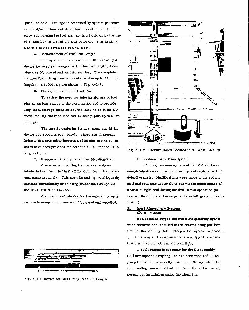
6. Storage of Irradiated Fuel Pina
To satisfy the need for interim storage of fuel
pins at various stages of the examination and to provide
long-term storage capabilities, the floor holes at the DP-
West Facility had been modified to accept pina up to 61 in.
in length.
The insert, centering fixture, plug, and lifting
device are shown in Fig. 401-2. There are 22 storage
holes with a criticality limitation of 25 pins per hole. In-
serts have been provided for both the 4O-in.- and the 61-in.-
long fuel pins.
‘7. Supplementary Equipment for Metallography
A new vacuum potting fixture was designed,
fabricated and installed in the DTA Cell along with a vac-
uum pump assembly. This permits potting metallography
samples immediately after being processed through the
Sodium Distillation Furnace.
A replacement adapter for the autoradiography
and waste compactor press was fabricated and ins+lled.
l!E==av,+=”....— ~.;,-, i.-..
L——u—n’—
.#4- -.::
I‘.
,&
=
-,–—
..-. .. . .
..
.1
\ \
-“--\
Fig. 401-2. Storage Holes I-mated in DP-West Facility
8. Sodium Distillation System
The high vacuum system of the DTA Cell was
completely disassembled for cleaning and replacement of
defective parts. Modifications were made to the sodium
still and cold trap assembly to permit the maintenance of
a vacuum tight seal during the distillation operation (to
remove Na from specimens prior to metallographic exam-
ination).
B. Inert Atmosphere Systems(P. A. Mason)
Replacement oxygen and moisture gettering agents
were received and installed in the recirculating purifier
for the Disassembly Cell. The purifier system is present-
ly maintaining an atmosphere containing typical concen-
trations of 20 ppm 02 and c 1 ppm H20.
A replacement boost pump for the Disassembly
Cell atmosphere sampling line bas been received. The
pump has been temporarily installed at the operator sta-
tion pending removal of fuel pins from the cell to permit
permanent installation under the alpha box.
.
.
Fig. 401-1. Device for Measuring Fuel Pin Length
2
.
..
The installation of the Butyl Acetate Removal Sys-
tem for the Metallography Cells has been completed and
the system is now operational. An average of 0.9 liters
of butyl acetate is being collected in a 24 hour period.
c. Mmipulator Maintenance and Development(G. R. Brewer, P. A. Mason, E. L. Mills)
Overhaul of the AMF manipulators at Wing 9 and
the CRL Model 8 manipulators at DP-West has continued.
The re-installation of AMF manipulators in the
Metallography Cells has eliminated the frequent break-
downs experienced with the CRL Model “L” manipulators.
Only one AMF manipulator required removal from the
cells for repair during the report period. As a result of
discussions with Central Research Laboratories regard-
ing the difficulties experienced with the Model ‘~L’l manip-
ulators, tests were performed at the factory. “Slack
tape eliminators” were designed by the factory and recom-
mended as a solution to the problems. One set of the
eliminators was purchased and will be installed to deter-
mine the effectiveness of the modification.
The AMF manipulators are being converted to a
CRL slave hand assembly, type SRL, to reduce wear prob
Iems and provtde a more. secure gripping action.
The spare CRL Mini-Manipulator has been modified
to permit straightening the slave arm during installation
in the Metallograph Compartment.
The experimental polyurethane boots obtained from
Central Research Laboratories proved satisfactory after
installation in the Disassembly and Metallography Cells.
An order for 24 of the boots has been received.
Dural pads for the metallography cell manipulators
were designed, fabricated and installed. Butyl acetate
solvent used in the metallography sample preparation
causes rapid deterioration of the standard neoprene pads.
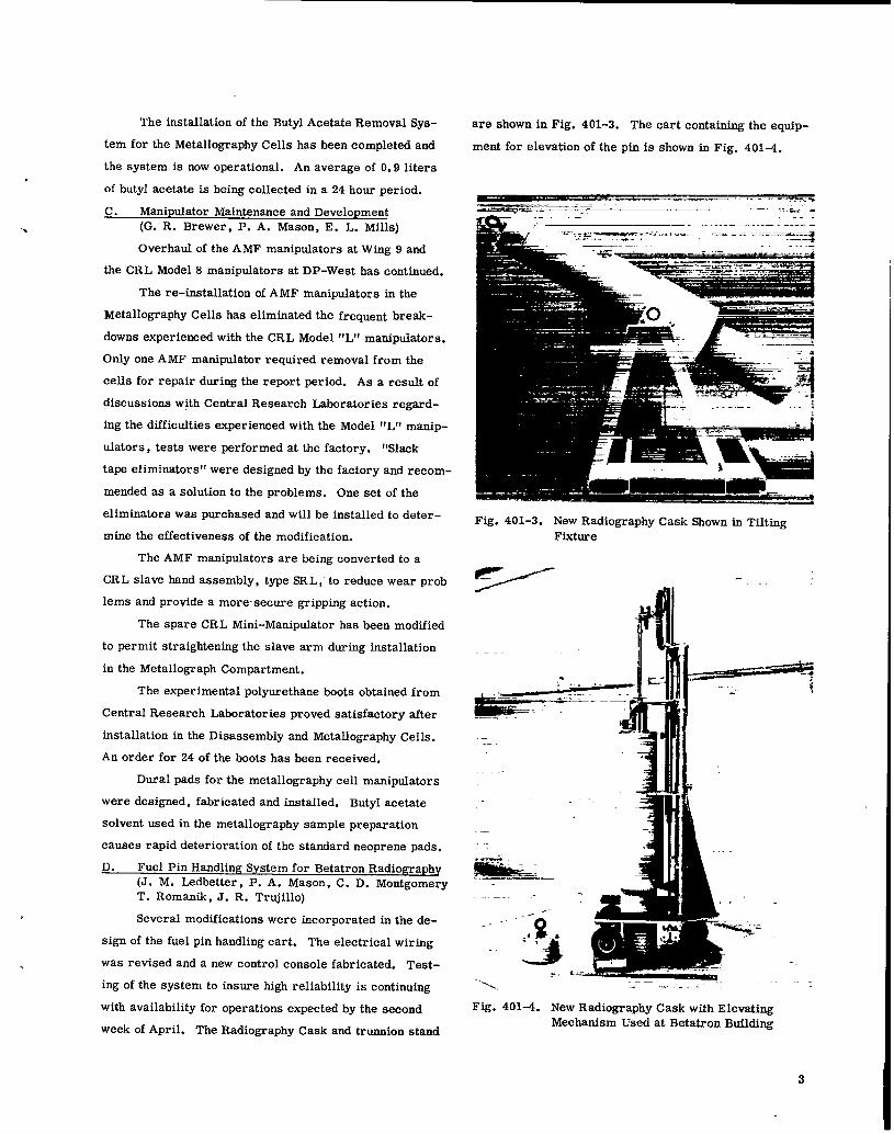
D. Fuel Pin Handling System for Betatron Radiography(J. M. Ledbetter, P. A. Mason, C. D. MontgomeryT. Romanik, J. R. Trujillo)
Several modifications were incorporated in the de-
sign of the fuel pin handling cart. The electrical wiring
was revised and a new control console fabricated. Test-
ing of the system to insure high reliability is continuing
with availability for operations expected by the second
week of April. The Radiography Cask and trunnion stand
are shown in Fig. 401-3. The cart containing the equip-
ment for elevation of the pin is shown in Fig. 401-4.
..- .. ---- >—.sin: -“’
-.:a. --..
./ ‘?.%. — ----=., =,--- — --= ‘-————=E
Fig. 401-3. New Radiography Cask Shown in TiltingFixture
5’--- dll -
ii’flif&“::””’.—
—
--- -“-o i
~~I
-“d~ -~.‘,!..... “-.= . . . .-, -”
Fig. 401-4. New Radiography Cask with ElevatingMechanism Used at Betatron Building
3

E. Status of Shipping Cask
Following a meeting at EBR-LI, it was determined
that LASL could handle the following casks: T-2, Han-
ford 14-Ton, Murphy, and possibly the TREAT units,
which may present some problems in unloading.
In order to maintain adequate shipping capacity,
and in view of the TAN Facility being phased out, it ap-
peared advisable to modify the two LASL vertical casks
(capacity for 19 pins) to be compatible with the HFE F-S
and HFEF-N loading ports.
Preliminary design was started in March 19’73 to
alter the cask arrangement to provide a separable base-
skid concept thus reducing the effective diameter of the
cask to c 33 in. which is a limiting dimension of the load-
ing ports. Cost estimates for the modification are
obtained from DOT, the fabrication would be started. It
is hoped that an early completion date can be obtained
since the phase-out of TAN Facility may be imminent
and also since the loading costs at TAN were - $1800
per shipment in the Third Quarter of I?Y 1973.
111. ANALYTICAL CHEMISTRY
1. Gamma Scanning(J. R. Phillips, T. K. Marshall, G. H. Mottsz,“J. R. Netm-chil, J. N. Quintana
a. 95Nb~765 keV)_~e~~rqt~o~~f_9~Er(756 keV&Wd___ga_m_m~=rg~@& The two adjoining gamma-ray peaksof 95
Zr (756 keV) and95
Nb (765 keV) are often summed
to obtain the relative burnup as a function of axial posi-
tion on an irradiated fuel pin. These two gamma photons
are separated by only 9 keV, thereby precluding the use
of single channel analyzers for determining their individ-
ual isotopic distributions. The net areas can be obtained
by fitting each of the two peaks with a summation function
consisting of a Gaussian function and three exponential
functions.1
A typical fitted spectrum of the 95 Zr(756 kev)
and ‘5 Nb (765 keV) gamma peak is shown in Fig. 401-5.
The capability of separating adjoining gamma peaks,95 95
in particular the Zr 756 keV and Nb 765 kev peaks,
is essent ial for the investigation of their individual
migration properties. This capability was used in
,0
.
to
10
- @2000 per cask.
When approval of the proposed modifications are
2
,0
EIW?G’r’ ● !+ KEV
Fig. 401-5.95
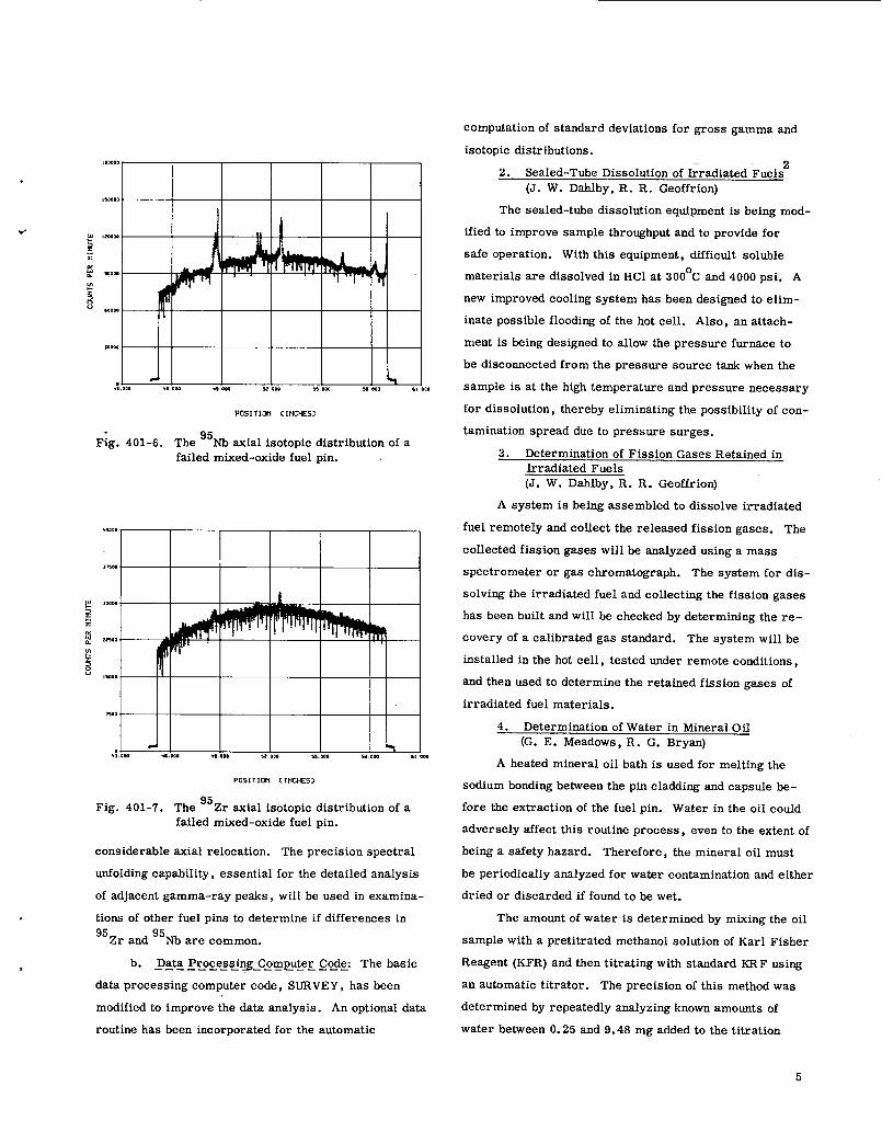
The fitted spectra for the Zr 756 keVad 95Nb 765 keV gamma-ray peakf3.
95measuring the Zr and ‘5 NI axial isotopic distributions
95zrindividually for a failed mixed-oxide fuel pin. The
isotopic distribution was determined by the analys ia of
its 724 and 756 keV gamma-ray peaks (Fig. 401-6). Each
data point is represented by error bars equivalent to one
standard deviation. There were four prominent spikes in
the95Zr activity at 48.78, 51.25, 52.62, and 56.26 in.
The95
Nb axial isotopic distribution (Fig. 401-7) over the
same fuel region was significantly different, with six re-
gions of high activity 48.78, 51.25, 52.62, 56.26,
58.24, and 58.96 in. Four of these regions,48. 78, 51.25,
52.62, and 56.26 in. ,95zr
corresponded to spikes in the
isotopic distribution. However, two of the95
lib spikes,
at 58.24 and 58.96 in. , did not have correspondingly high95
Zr concentrations. Also, the relative magnitudes of
the 95Nb spikes were significantly different from the95Zr spikes.
The results indicate that the migration properties95
of Zr and ‘5 Nb are significantly different, at least in
this failed fuel pin, with the95~ isotope undergoing
computation of standard deviations for gross gamma and
isotopic distributions.
F;g. 401-6.
FOSITICti CItiCKES)
The ‘5 Nb axial isotopic distribution of afailed mixed-oxide fuel pin.
POSITIUi C1NCt9ZS>
Fig. 401-7. The95
Zr sxial isotopic distribution of afailed mixed-oxide fuel pin.
>
cons iderable axial relocation. The prec is ion spectral
unfolding capability, essential for the detailed analysis
of adjacent gamma-ray peaks, will be used in examina-
tions of other fuel pins to determine if differences in95
Zr and95
Nb are common.
b. Data Processing Com~uter Code: The basic—-—-——— ———— .—— ——
data processing computer code, SURVEY, has been
modified to improve the data analysis. An optional data
routine has been incorporated for the automatic
2. Sealed-Tube Dissolution of Irradiated Fuels2(J. W. Dablby, R. R. Geoffrion)
The sealed-tube dissolution equtpment is being mod-
ified to improve sample throughput and to provide for
safe operation. With this equipment, difficult soluble
materials are dissolved in HC1 at 300°C and 4000 psi. A
new improved cooling system has been designed to elim-
inate possible flooding of the hot cell. Also, an attach-
ment is being designed to allow the pressure furnace to
be disconnected from the pressure source tank when the
sample is at the high temperature and pressure necessary
for dissolution, thereby eliminating the possibility of con-
tamination spread due to pressure surges.
3. Determination of Fission Gases Retained inIrradiated Fuels(J. W. Dahlby, R. R. Geoffrion)
A system is betng assembled to dissolve irradiated
fuel remotely and cof.lect the released fission gases. The
collected fission gases will be analyzed using a mass
spectrometer or gas chromatography. The system for dis -
solving the irradiated fuel and collecting the fission gases
has been built and will be checked by determining the re -
covery of a calibrated gas standard. The system will be
imstalled in the hot cell, tested under remote conditions,
and then used to determine the retained f iss ion gases of
irradiated fuel materials.
4. Determination of Water in Mineral Oil(G. E. Meadows, R. G. Bryan)
A heated mineral oil bath is used for melting the
sodium bonding between the pin cladding and capsule be-
fore the extraction of the fuel pin. Water in the oil co~d
adversely affect this routine process, even to the extent of
being a safety hazard. Therefore, the mineral oil must
be periodically analyzed for water contamination and either
dried or discarded if found to be wet.
The amount of water is determined by mixing the oil
sample with a pretitrated methanol solution of Karl Fisher
Reagent (KFR) and then titrating with standard KRF using
an automatic titrator. The precision of this method was
determined by repeatedly analyzing known amounts of
water between O.25 and 9.48 mg added to the titration
5

vessel. The relative standard devtation was 1, 8, and
I@, in titrating 9.48, 0.49, and 0.25 mg of water, re-
spectively. The poorer precision of the method for
small quantities of water is a result of a variation of
* O.02 ml in dispensing of the KFR. The method bad a
positive bias of 9% in measuring 0.25 to 0.5 mg of water.
The volubility of water in mineral oil at 74°F was
estimated by equilibrating mineral oil with excess water,
centrifuging to remove entrained water, and analyzing
the mineral oil for water using KFR. The oil contained
32 + 5 Kg of water per milliliter of oil. Mineral oil sam-
ples received to date have contained lesser amounts of
water than this value.
Iv. REQUESTS FOR DRDT
A. Examination of Irradiated Materials(R. N. Abernathy, K. A. Johnson, M. E. Lazarus,R. A. Morris, J. R. Phillips, J. W. Schulte,G. R. Waterbury, W. F. Zelezny)
During this Third Quarter of FY 1973 forty-six
irradiated capsules were received. The distribution is
as follows: GE - 17; HEDL - 20; BMI - 5; LASL - 2;
and WARD -2.
General Electric Company: Examinations performed
on irradiated fuel assemblies received on February 14,
1972, October 22, 1972, and March 21, 1973 are shown
as follows:
Visual examination was performed on GE capsules
F8L, F8N, F80, F8P, F8Q, FOB, and FOD.
Sectioning was done on pins l?4A and E2R.
Three samples of fuel from pins numbered GE-
FOA-F, GE-FOA-J, and GE-FOC-J and two samples of
cladding from pins numbered GE- FOA and GE-FOC were
amalyzed for oxygen content. A spectrochemical analysis
for impurities in the fuel was done on section F of GE-
FOC .
Sections B, D, E, and F of GE-E2R and sections
E of both GE-FOA and GE-FOC were examined using the
shielded microprobe.
The atom percent burnup was determined on each
of the following pins: GE-FOA, GE-FOC, GE-F12P,
GE-F12Q, and GE-E2R, using an isotope dilution mass
spectrometric method.
Microstructural examinations consisting of micro-
photography, alpha and beta-gamma autoradiography and
optical microscopy (including mosaics) were carried out
in an Ar atmosphere on specimens listed in Table 401-1.
TABLE 401-1
MICROSTRUCTURAL ANALYSIS OF GE MATERIALS
No. Samples EMXGE Pin No. Fuel and Clad jSample Prep. )
FOc 2 1
E2R 7 2
F4A 1
Ten structural capsules (L-16 Series) were receiv-
ed from GE on February 16, 1973 and are being stored
until time is available to work these into the priority
schedule.
Hanford Engm“ eering Development Laboratory:
During this report period (3rd Quarter FY 1973) ship-
ments were received as follows: 9 capsules on February
1 and 11 capsules on March 21. Examinations performed
on HEDL materials during this period are listed in this
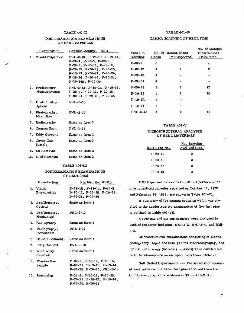
section. (’Mbles 401-11 and 401-111).
The fuel pins listed in Table 401-IV were nondestruc-
tively examined using the gamma scanner.
Atom percent burnup was determined by dissolving
and analyzing a cross-section sample of fuel and clad on
HEDL P-17A-33.
The pin gas was analyzed mass spactrometricaUy
in HEDL-P-20-21, while both the cover gas and pin gas
were analyzed in the following pins: HEDL-P-19-IR,
P-19-14, P-20-5, P-20-12, P-20-15, P-20-28 , P-20-36,
and PNL-2-13.
Microstructural examinations consisting of micro-
photography, alpha and beta-gamma autoradiography, and
optical microscopy (including mosaics) were carried out
in an Ar atmosphere on the specimens as listed in Table
401-V.
Los Alamos Scientific Laboratory: This section
contains carbide and nitride fuel pins, the technical eval-
uation of which is being carried out by L4SL personnel
under the Advanced Pu Fuels Program.
.
.
.
1.
2.
3.
4.
5.
6.
7.
8.
9.
10.
1.
2.
3.
4.
5.
6.
‘7.
8.
9.
10.
TABLE 401-11
lXX3TIRRAlXATION EXAMINATIONSOF HEDL CAPSULES
Examination
Visual Inspection
PreliminaryMeasurements
Profilometry,Optical
Photography,Max. BOW
Radiography
Gamma Scan
Eddy Current
Cover GasSample
Na Removal
Clad Removal
Capsule Identity, HEDL
PNL-2-13 , P-19-lR , P-19-14 ,P-20-1, P-20-3 , P-20-5,P-20-9, P-20-11, P-20-12 ,P-20-15 , P-20-18, P-20-20,P-19-23 , P-20-21, P-20-24,P-20-26, P-20-28 , P-20-32,P-20 -34R, P-20-36
PNL-2-13 , P-19-IR , P-19-14 ,P-20-5, P-20-12, P-20-15,P-20-21, P-20-28, P-20-36
PNL-2-13
PNL-2-13
Same as Item 2
PNL-2-13
Same as Item 2
Same as Item 2
Same as Item 2
Same as item 2
TABLE 401-11.I
POSTIRRAIMATION EXAMINATIONSOF HEDL PINS
Examination
VisualExamination
Profilometry,Optical
Profilometry,Mechanical
Radiography
Photography,Incremental
Gamma Scanning
Eddy Current
Wire WrapRemoval
Fission GasSample
Sectioning
Pin Identity, HEDL
P-19 -I.R, P-19-14, P-20-5,P-20-12, P-20-15 , P-20-21,P-20-28 , P-20-36
Same as Item 1
PNL-2-13
Same as Item 1
PNL-2-13
Same as Item 1
PNL-2-13
Same as Item 1
P-20-5, P-20-12, P-20-15,P-20-21, P-19-lR, P-19-14,P-20-28 , P-20-36, PNL-2-13
P-20-5, P-20-12 , P-20-15,P-20-21, P-19-lR, P-19-14,P-20-28 , P-20-36
Fuel PinNumber
P-2 o-5
P-20-12
P-20-15
P-20-21
P-20-28
P-20-36
P-19-I.R
P-19-14
TABLE 401-IV
GAMMA SCANNINGOF HEDL PINS
No. of Gamma scansGross Multispectral
8
4 1
4
4
4 2
4 1
4
4
PNL-2-13 4 2
TABLE 401-V
No. of IsotopicDistributionsCalculated
9
12
10
10
MICROSTRUCTURAL ANALYSESOF HEDL MATERIALS
No. SamplesHEDL Pin No. Fuel and Clad
P-20-12 3
P-20-5 3
P-20-15 3
P-20-21 3
,
BMI Experiment{ --- Examinations performed on
nine irradiated capsules received on October 11, 1972
and February 16, 1973, are shown in Table 401-VI.
A summary of the gamma scanning which was sp-
plied to the nondestructive examination of five fuel pins
is outlined in Table 401-VII.
Cover gas and pin gas samples were analyzed in
each of the three fuel pins, BMI-3-2, BMI-3-4, and BMI-
3-5.
Microstructural examinations consisting of micro-
photography, alpha and beta-gamma autoradiography, and
optical microscopy (including mosaics) were carried out
in an Ar atmosphere on six specimens from BMI-3-5.
Gulf United Experiments --- Postirradiation exami-
nations made on irradiated fuel pins received from the
Gulf United program are shown in Table 401-VIII.
7

TABLS401-VIPUST2RRAD2AT101iEXAM2NATkJNSOF cAPSULES AND P2NS FROM BM2
JxunlMuoJ Cwale ldentNv. BMI Fin Identity, BMI
1. Vimml Zrbspectloll 1-1, 1-2, 2-2, 2-6, 2-7 $-2, 24, ‘4-s
Z Relttn. Meamrmmecdi SUlmultsml
S. Rofilomrtsy - CW4icd &ma 2s Item 1
4. Phc402c@y, FuN Lm@h Sme w Izem 1 3-2, 2+, 2-s
5. Ph0t02rWhJ, Illcmnwntll Zama u Nem 1 2-2, s+, 2-s
6. Radiography maw u Item 1
7. Oalnm ¨ng Sameulteml
S. Eddy current Slmmuzteml S-2
9. Cover Ciu Eamplb2 2-2, 2-6, 2-2, 3+, S-6
10. Na Remon2 2-:, 34, 3-6
11. (?2s6 Renmti 2-2, s+. 2-6
22. tiOftiO~tiy, 26eclunk12
12. M!crometar Xewiremec.ts
14. aecuonhg
S-2, S-4
S-6
S-2, S-4 , 3-s
TABLE 401-VII
GAMMA SCANNINGOF BMI FUEL PINS ‘
No. of IsotopicFuel Pin No. of Gamma Scans DistributionsNumber G= Multispectral Calculated
BMI-1-1 4 1 10
BMI-1-2 4
BMI-2-2 4
BMI-2-6 4
BMI-2- 7 4
Gamma scanning, including gross and complete
spectral scans, was applied to the examination of the fuel
pins listed in Table 401-IX.
The following four samples were examined using the
shielded electron microprobe: UNC- 189-F, -198 -K,
-200-G, and -206-E.
Cover gas samples in uNc-97 and uNC-113 and pin
gas samples in UNC-93, UNC-94, and UNC-105 were
analyzed mass spectrometrically.
Atom percent burnup was determined on each of the
following ten fuel pins: UNC-187, -189, -191, -192,
-195, -197, -198, -200, -206, and -208.
Clad samples from the following ten pins were
cleaned and prepared for density measurement: UNC-187,
TABLZ 401-VID
POBT2RRAD2AT13N SXAM22L4T20N2 OF OU CK’EULES AND PINS
Jxmlhum
1. Pbc4waPhy , FuN I.u@hand Muimum
Y.. 0“ 2Mlpl~
S. Nt Removal
4. Clsd Remonl
6. G-nuns &an
6. Eddy Current
7. V2SU2Il!spact!on
8. PreIlmlmryA2essuremenb
s. Pr02U0me2ry,
0*~
10. P&tops@y, Full 1.en6tbd Ksxlmum SW
11. Pba~mphy, 2m2rmnellW
lx. SOdlcilllu
22. Ns Dic.21UaNon
24. DeM1ty Meuucemmtz
@-ah I&cdur. UNc114, 18S, 186, 202, 202.204, 203
92, 94, 67, 102, 110,11s
93, 24, 87, 10s, 110,llz
93, 94, 4’7, 100, 110,11s
202, 20s. 204, 206, 104
186, 202, 20S, 204, 202
~ r&@4N,. ONc
S2, 64, la
191, 1S2, 195, 147,198, 200, 204
92, 94. S7, 102, 110,222
s3, M, 67, 10S, 110,122
6S, W, 47, 106, 110,lU
*S, 44, 47, 10s, 110,122
S2, 64, S7, 106, 110,112
62, 94, 126, 1s1, 192.N6, WY, Iw, 200. X6
1s2 , 196, 197
Ml, 1ss, 191, 162, 1s4,194, In, 1s8, 2000206,204
TABLE 401-IX
GAMMA SCANNINGOF GU PINS
I’Jo. of IsotopicFuel Pin No. of Gamma Scans DistributionsNumber Gross Multispectral Calculated
UNC-106 - 1 8
UNC-202 4
UNC-203 4
UNC-204 4
UNC-205 4
-189, -191, -192, -195, -19’7, -198, -200, -206, and
-208.
Microstructural examinations consisting of micro-
photography, alpha and beta-gamma autoradiography, and
optical microscopy (including mosaics) were carried out
in an Ar atmosphere on the specimens listed in Table
401-X.
LASL Experiments --- Examinations performed on
irradiated fuel pins from the LASL-identified pins are
listed in Table 401-XI.
Four gross gamma scans were obtained on each of
two fuel pins, 1.ASL-K-38B and LASL-K-43.
.
.
.
.
8

.- .- .- ------ ----- -TABLE 401-X
MICROSTRUCTURAL ANALYSES OF GU MATERIAIS
LASL-K-36B , -K-38B , -K-43 , -K45 , ‘K4Y , ‘K-au ,
and -K-51.
~o clad samples from LASL-K-49 were cleaned
and prepsred for density measurement.
Microstructural examinations consisting of micro-
photography, alpha and beta-gamma autoradiography,
optical microscopy (including mosaics) were carried out
in an Ar atmosphere on 6 fuel and clad specimens from
I.ASL K49 and 5 fuel and clad samples from I.ASL K-
36B. One sample was also prepsred for EMX from
LASL phl K-49.
ORNL Experiments --- Pulsed eddy current scan-
~w was mde of ORNL 43-N1.
WARD Experiments --- Examinations performed
on irradiated fuel pins received on February 1, 1973
are listed in Table 401-XIL
TABLE 401-XJ.I
POSTIRRADIATION EXAMINATIONSOF WARD CAPSULES Am PINS
Pin No. SamplesIdentity Fuel and Clad ~ EMX Prep.
UNC-194 3
UNC-187 3 14
UNC-189 3 1 2
1UNC-206
UNC-192
UNC-195
UNC-197
UNC-200
UNC-208
UNC-191
UNC-198
UNC-93
2
1
2
2
2
3
4
3
3
2
2
2
2
1
1
1
1
UNC-94 4
UNC-105 3
UNC-192 1
Capsule Identity, Pin Identity,WARD WARD
W4F , W8F W4F, W8F
w41? , W8F
W4F, W8F W4F , W8F
W4F , W8F
W4F, W8F
W4F , W8F
W4F, W8F
W4F, W8F
W4F , W8F
W4F , W8F
W4F , W8F
W4F, W8F
Examination
VisualInspection
TABLE 401-XI
X32TJBRADL4T~N SXAMINAT3UNS OF C4P3ULES FROM lA3L 1.Zsamkuum
VimulIIWeatlom
CsralleMOtllit,.3A6L
K-3SB, K+s
K-WE , K+3
Pin Irhtuv. 3ASL
K-36B. K-461.2.
2. preliminaryMeasurements
Rofllornctry,Ogdod
s.4.
6.
6.
K-2SB, K+3
K-WB , K-43
K-38B , K-43
K-26B, K-43
Profilometry,Optical
3.Gulmla .9m.iw
Eddy current
Phot.agcslhy ,Fu31La@h
Phdc.6r@y,Mulmlml sow
Photography,Full Length
4.‘1. K-S6B . K-43 K-96B, K+3
K-36B, K46
K-36B, K-38B,K-43 , K-46, K-49,K-50, K-51
K-36B
K-36B, K-49
Photography,Incremental
Photography,Maximum BOW
5.8. P!AOgmpily,horemenld
K-36B, K49
9. cmSuwung K-36B, K-36B, K-43,K+6, K-49, K-sO, K-5L 6.
10. N. Rertwd
11. Clad Removal
ls. Ro(ilometiy ,
MdmrJ.Xl
K-38B, K46
K-46 Radiography
Gamma Scanning
‘7.
8.
9.
10.
13. C4c610nlrg
Eddy Current
Cover GasSampling
Na Removal
Clad Removal
Section K of LASL-K-49 wsa examined using the
shielded electron microprobe.
The water and chlorine contents were determined in
a sample of mineral oil used as the heat transfer medium
in melting the sodium bonds in irradiated fuel pins.
Msss spectrometry was applied to the analysis of
cover gas and pin gas in each of the following fuel pins:
11.
12.
13. W4F , W8FTemperatureMeasurements
9
v. QUALITY ASSURANCE
Microstructural Anallgi~ The Microstructural————--—————
Analysis procedure for diagnostic examinations has been
revised and updated. Traveler documentation has been
expanded and is in use. A training program for operators
has been completed and certification records prepared.
Calibration procedures have been written. Instruments
have been calibrated, labeled, and required documents
have been supplied to the Quality Assurance Manager.
An audit conducted by the Quality Assurance Man-
ager has been completed and an audit report prepared.
Hot Cell Examinations: The Quality Assurance Plan---- —_______
for Hot Cell Examinations has been revised. Procedures
for Hot Cell Diagnostic Examinations have been revised
and updated. New procedures have been added. The
training program has been extended to include the use of
designated trainees under the supervision of certified
operators.
Calibrated instruments are in use, labels in place
and records have been supplied to the Quality Assurance
Manager.
An audit was conducted by the Quality Assurance
Manager in both the Wing 9 and DP West areaa and an
audit report was prepared.
C_hg~iEa~~~~gi~ The changes made in the Ana-
lytical Quality Assurance Plans have been approved and
are betng used. The traveler system has been revised
and new forms prepared. The revised Analytical Chem-
istry Quality Assurance Procedures have been accepted
by all sponsors of diagnostic examinations and are in-
corporated into the quality assurance system. Certifica-
tions for analysts have been revised and updated.
The recall system for scheduled recalibration of
instruments is being used and documentation is being
supplied to the Quality Assurance Manager.
An audit was conducted by the Quality Assurance
Manager in all of the Analytical Chemistry areas and an
audit was prepared.
VI. REFERENCES
1. W. M. Sanders and D. M. Helm, “An AnalyticalMethod for Unfolding Gamma-Ray Spectra, ”Los Alamos Scientific Laboratory report I.A-4030 (March 1969).
2. frQ@erly SatUS Report on the Advanced PM.cmhunFuels Program, January 1- March 31, 1971, t’Los Alamos Scientific Laboratory report LA-4693-MS, p. 6, (1971).
‘“
.
.
10
PROJECT 463
HIGH PERFORMANCE LMFBR FUEL MATERIALS
Persoti in Charge: R. D. BakerPrincipal Investigator: J. L. Green
.
I. INTRODUCTION
The primary objective of this program is the over-
all evaluation of the most promising of the candidate fuel
systems for advanoed LMFBR application. Emphasis
currently is placed on the study of the relative merits of
stainless steel clad nitride and carbide fuels under con-
ditions that appropriately exploit the potential of these ma-
terials to operate to high burnup at high power densities.
The major portion of the program is the evaluation of the
irradiation performance of these fuel element systems.
A continuing series of irradiation experiments is baing
carried out under steady state conditions in fast reactor
environments to assess the effects of damage and burnup
on stainless steel clad, carbide and nitride fuel elements.
These experiments are designed to investigate fuel swell-
ing, interactions between the fuel ad clad and thermal
bonding medium, fission gas releaae, and the migration
of fuel material and fission products as a function of burn-
UPand irradiation conditions. In addition, experiments
are keing designed to allow the study of the effects of rap-
id, overpower, reactor transients on carbide and nitride
fuel assemblies. Contiguous efforts are necessary in the
development of fuel material preparation and fabrication
procedures as well as the techniques required for the
characterization of fuel materials both before and after
irradiation.
A second objective in the program is the determin-
ation of thermophysical, mechanical and chemical proper-
ties and characteristics of plutonium-containing ceramics
that are required for their evaluation and use as fuel
materials. A broad range of capabilities in this area has
been developed, including the study of (1) phase relation-
ships using differential thermal analysis, (2) thermal
transport, (3) thermal atabili~ and compatibility, (4)
hot hardness and its temperature dependence, (5) struc-
ture and phase relationships using high temperature x-ray
and neutron diffraction, (6) thermal expansion, and (7)
compressive creep rates as a function of temperature and
stress. Several of these techniques are availakle for use
with irradiated fuels.
If. IRRADIATION TESTf.NG
The objective of the irradiation testfng program is
the overall evaluation of the most promising of the csndi-
date fuel systems for advanced LMFBR application. The
irradiation experiments are carried out under conditions
that take advantage of the potential of these materials to
operate tn high burnup at high power densities.
A. Synthesis and Fabrication(K. W. R. Johnson, J. G. Reavis, H. Moore,
R. Walker, C. Baker)
1. Process Development. Development work
on a process for the preparation of high density, single
phase UOO&O. ~C by reduction of U02 -Pu02 mixtures
by heating in vacuo with graphite has previously been re-1,2
ported. Three additional production scale (25 Og)
batches of carbide have been produced by this method for
the purpose of further investigation of the effects of pro-
cessing variables. The products of the reduction step
11
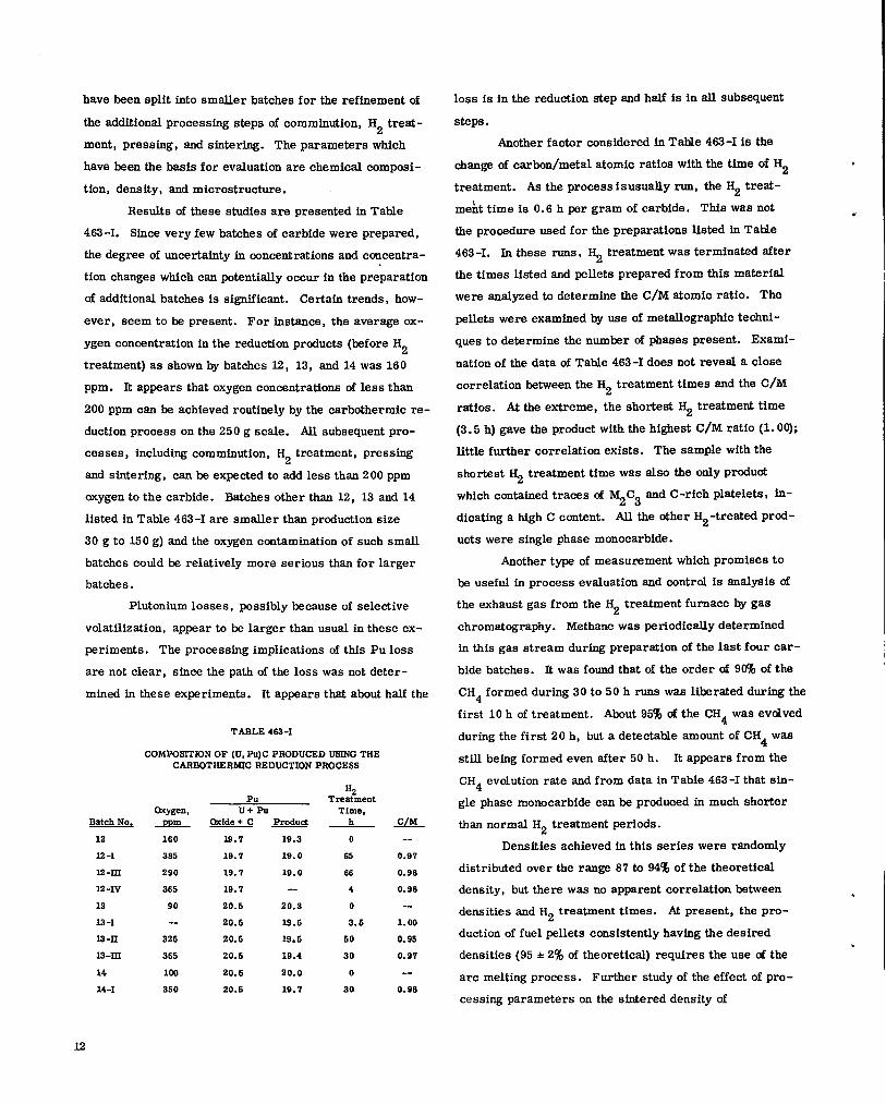
have been split into smaller batches for the refinement of
the additional processing steps of comminution, H2 treat-
ment, pressing, and sintering. The parameters which
have been the basis for evaluation are chemical composi-
tion, density, and microstructure.
Results of these studies are presented in Table
463 -I. Since very few batihes of carbide were prepared,
the degree of uncertainty in concentrations and concentra-
tion changes which can potentially occur in the preparation
of additional batches is significant. Certain trends, how-
ever, seem to be present. For instance, the average ox-
ygen concentration in the reduction prcducts (before H2
treatment) as shown by batches X2, 13, and 14 was 160
ppm. It appears that oxygen concentrations of less than
200 ppm can be achieved routinely by the carbothermic re-
duction process on the 250 g scale. AU subsequent pro-
ces ses, including comminution, H2 treatment, pressing
and sintering, can be expected to add less than 200 ppm
wygen to the carbide. Batches other than 12, 13 and 14
listed in Table 463-I are smaller than production size
30 g to 150 g) and the oxygen contamination of such small
batches could ke relatively more serious than for larger
batches.
Plutonium losses, possibly because of selective
volatilization, appear to be larger than usual in these ex-
periments. The processing implications of this Pu loss
are not clear, sfnce the path of the loss was not deter-
mined in these experiments. It appears that about half the
TABLE462-1
COhWOSITIONOF (U,Pu)CPRODUCEDUSINGTHECARBOTHERMICREDUCTIONPROCESS
BatchNot12
12-1
ls ax
12-N
13
13-I
Is -n
la-xxx
14
14-1
Oxygen,-PP!!L
160
365
290
365
90
.-
325
365
100
350
PuU+PU
Oxide+ C ProduclIS.7 19.319.7 19.019.7 19.019.7 --
20.s 20.320.5 ls.520.5 19.s20.6 19.420.s 20.020.6 19.7
%Treatment
Time,h
o6566403.5
5030
0
20
S.&L--
0.970.980.98--
1.000.950.97--
0.98
loss is in the reduction step and half is in all subsequent
steps .
Another factor considered in Table 463-I is the
change of carbon/metal atomio ratios with the time of H2
treatment. As the process is usually run, the H2 treat-
meht time is 0.6 h per gram of carbide. This was not
the procedure used for the preparations listed in Takle
463 -I. In these rune, ~ treatment was terminafid S.fter
the times listed and pellets prepared from this material
were analyzed to determine the C/M atomio ratio. The
pellets were examined by use of metallographic techni-
ques to determine the number of phases present. Exami-
nation of the data of Table 463-I does not reveal a close
correlation between the H2 treatment times and the C/M
ratios. At the extreme, the shortest H2 treatment time
(3. 5 h) gave the product with the highest C/M ratio (1. 00);
little further correlation exists. The sample with the
shortest ~ treatment time was also the only product
which contained traces of ~C3 ~d C-rich Platelets I ~-
dicating a high C content. All the other H2-treated prod-
ucts were single phase monocarbide.
Another type of measurement which promises to
be useful in process evaluation and central is analysis of
the exhaust gas from the ~ treatment furnace by gas
chromatography. Methane was periodically determined
in this gas stream during preparation of the last four car-
bide batches. It was found that of the order of 90% of the
CH4 formed during 30 to 50 h runs was liberated during the
first 10 h of treatment. About 95% of the CH4 was evolved
during the first 20 h, but a detectable amount of CH4 was
still being formed even after 50 h. It appears from the
CH4 evolution rate and from data in Table 463-I that sin-
gle phase monocarbide can be produoed in much shorter
than normal H2 treatment periods.
Densities achieved in this series were randomly
distributed over the range 8’7to 94% of the theoretical
density, but there was no apparent correlation between
densities and H2 treatment times. & present, the pro-
duction of fuel pellets consistently having the desired
densities (95 *2% of theoretical) requires the use of the
arc melting process. Further study of the effect of pro-
cessing parameters on the sintered density of
.
.
.
L2

.
4
carbothermicafly prcduced material will be necessary.
A major effort has been directed toward develop-
ing and applying QA procedures for use in the fuel prepar-
ation task in the program. A number of formalized pro-
cess control procedures have been prepared. These in-
clude detailed processing instructions, data forms, trans-
fer and storage documentation, sampling procedures, etc.
Considerable progress has been made in the area of in-
strument control and calibration. A large number of in-
struments have been designated as data gathering devices,
and, therefore, must be calibrated prior to use. The cal-
ibration system involves several different areas:
a.
b.
c.
d.
e.
f.
g.
identifying data gathering devices,
preparing calibration procedures for in-struments to be calibrated by projectpersonnel,
training and certifying personnel,
procuring certified standards and devicesto be calibrated and certffied by the manu-facturer,
obtaining calibrations and certificationsfrom standards laboratories when required,
carrying out routine calibrations and tagging,and
maintaining local records of calibrationactivities.
All calibrated instruments and standards are included in
the central files for calibrated instruments and are part
of the QA recall system.
B. EBR-Lf Irradiation Testing-(J. O. Barrier, K. W. R. Johnson, J. F. Kerrisk,T. W. Latimer, L. L. Marriott, H. E. Strohm)
The purpose of the EBR-11 testing program is the
evaluation of the steady-state irradiation behavior of high
performance fuel element systems for application in ad-
vanced LMFBR reactors. Several series of carbide- and
nitride-fueled experiments have been initiated in the past
several years. The main objectives of the irradiations
are: (1) the development of fuel element designs for use
with each fuel type; (2) the determination of the irradia-
tion behavior of the fuel materials; (3) a comparison of
sodium and helium bonding; (4) a comparison of different
cladding alloys; and (5) the evaluation of the overall ir-
radiation performance of the fuel element systems. The
majority of the experiments under test or that have been
completed have been encapsulated. Most of the experi-
ments that are currently available for irradiation or that
are befng designed are singly clad.
Fourteen series of ex~riments have been origi-
nated. The description and status of these series are
summarized fn Tables 463-II to 463-IX. In order to bet-
ter define the status of those experiments which are under-
going postim%diation examination, the following steps are
referenced in the tables:
1. Capsule Examination
1.1 Visual examination
1.2 Preliminary Measurements(radfation measurements, etc. )
1.3 Profflometry
1.4 photography
1.5 Radiography
1.6 Eddy Current Test
1.’7 Gamma Scau
1.8 Cover Gas Analysis
1.9 Deencapsulation
2. Element Examination
2.1
2.2
2.3
2.4
2.5
2.6
2.7
2.8
2.9
2.10
2.11
2.12
2.13
Visual Examination
Profilometry
Photography
Eddy Current Teat
Fission Gas Analysis
sectioning
Autoradiography
Metallography
Burnup
Clad Density
Special Tests
Data Reduction
Report Preparation
Table 463-II describes the Kl, K2, and K3 series
tests. In these experiments single-phase, high-purity,
uranium -plutonium mono carbide peflets are sodium
bonded to Type 316 stainless steel cladding. In general,
the operating linear power ratings of the capsules are rel -
atively high (approximately 30 ICw/ft). Three tests M very
high power (> 45 Kw/ft) were included to determine the
effect of high thermal stresses and high fuel temperatures
on fuel element behavior. Indications of element cladding
X3

TABLE463-ff
tmRncsKI, x2, AND K3 ENCAPSULATED CMB~E EXPERIMENT
E.xpmt. .&
K-3 6B
K-37B
K-36B
K-39B
K-42B
K45
K-50
K-5 1
K-43
K-44
K-45
Ii-46
Fuel Tme
(U. 6PU0 Z)c
(uo:*PUOOJc
(u. *PUOOZ)c(uo” J%lo Z)c
. .
(U0,8PU002)C
(uoo ~puooJc
(U. ~Puo ~)c
(uo”6PUO”.JC,.
(U. +mo ,.JC
(uo” ~puo” Jc. .
(“0. 8PU0. 2)C(U. *PUO ,JC. .
?hdDensity,% Theo.
90
90
90
90
90
95
95
95
94
94
94
84
Max.Bondand h clad Linenr
Diamctml CIA O.D. x I.D.,g Power,Gap, in. I’m in. J@&
Series K1
Na-O. 01S SA-316SS 0.300 X 0.260 30
Na-O. 015 5A-31655 0.300 X 0.260 30
Na-O. 015 6A-31655 0.300 X 0.280 30
Na-O. 015 6A-31655 0.300 X 0.280 30
Na-O. 015 sA-i316SS 0.300x 0.280 30Series K?
Na-O. 020 6A-3 16SS 0.300 X 0.260 45-50
Na-O. 020 SA-316SS 0.300 X 0.280 45-50
Na-O. 020 SA-316SS 0.300 X 0.280 45-50
Sertes X3
Na-O. 020 SA-316SS 0.300”x 0.280 30
Na-O. 020 SA-318SS 0.300 X 0.280 30
Na-O. 020 6A-31666 0.300 x 0.2s0 30
Na-O. 020 SA-316SS 0.300 X 0.280 30
MaximumCenterline‘$emm. ‘c
1165
1165
1165
1165
1165
1400
1400
1400
1150
1150
1150
1150
QOsl CurrentBurnup, Burnup,J4&%L- Status
6
6
6
101
6
5
6.5
8
s
s
5
5
6.8
3.2
6.4
6.4
5.0
4.0
4.0
3.9
6.1
6.1
3.0
2.9
Exam, 2. 8“
Exam, 1.7b’e
Exam, 1.7°’e
EBR-11, Un-assigned
Completedd
Exam, 2. 8e
Exam, 1.9e
Exam, 1.9e
Exam, L Se
EBR-11,X162
Exam, 1.7f
Exam, 2.4e
aScries 1 and 3 experiments are 93% enriched in 235U. Series 2 experiments are 97% enriched in 233
U. All fuel fs single phase.,.“K-37B was damaged during reconstitution of X152 to the extent that it cannot he irradiated further.
CK-38B was damaged during reconstitution of X152. Additional irradiation was completed.
%eported in LA-iG69-Ms
‘Element cladding failure indicated.fNondestructive examination completed. Capsule stored for poseible irradiation of failed element.
gDimeM iOnS Sre nornhd.
h6A = solution annenlsd
iOrigiusl goal hurnup was 6 at.%. New AIP request for further irradiation in prepsration.
failure were found at EBR-11 in several experiments from
these series; five in subassembly X119B, one from133xe
X142, and two from X152, using y-scanning for .
Examinations of these experiments in the LASL hot cells
confirmed these failures. Complete postirmrdiation ex-
amination of the failed experiments is currently under way.
Table 463-III describes the Series U1300 experi-
ments. These experiments contain two-phase, ursnium -
plutonium carbide fuel pellets which are helium bonded to
either Type 316 stainless steel or fncoloy 800 cladding.
Two methods for the accommodation of fuel swelling were
investigated in this series, i.e. , the introduction of inter-
nal porosity by the use of either low-density solid fuel pel-
lets or high-density cored @lets. These experiments
reached their goal burnup of 10 at. % in subassembly X142
14
after operation at moderate linear power ratfngs (approx-
imately 20 Kw/ft). Indications of element cladding fail-
ure for three experiments were found at EBR-11 using Y-133
scanning for Xe. These element faflures have been137
confirmed by y-scanning for Cs at LASL. All of the
capsules in the series are currently undergoing nonde-
structive or deetmctive examination in the LASL hot cells.
The Series U1950 experiments are described in
Table 463-IV. In these experiments, either two-phase or
single -phase carbide fuel is helium bonded to Type 304 or
316 stainless steel or to fncoloy 800 cladding. Fuel den-
sities range from 75 to 98% cd theoretical. These exper-
iments are currently at about three-fourths of their goal
burnup after operation at low linear power (10 to 15 Kw/ft).
.
.

,.TABLE463-lIf
S2RIES1200ENCAPSULATEDCARBIDEEXPERIMENTS
.
~.
Max.Fuel Bond end clad Linear
Expmt. Dcnsit~ Diametral Cladd O.D. X I.D.., Power,~ Fuel TWa % Theo Gam in. Type in.- Z&/&
U93
U94
U9‘1
U98
U105
U106
Ullo
,U119
U114
MC+5% M2C3
MC+5% M2C3
MC+5% ?r$C3
MG5% qc3
MC+5% ~c3
‘-s% ‘2C3
MC+lC%~C3
Mc+lc% ~c3
MC+1O%M2C3
%= (U. *5PU015). .
84
63
34
34
76
75
96b
96b
96b
He-O.004
He-O. 007
He-O.. 004
He-O.007
He-O. 008
He-O. 009
He-O. 014
He-O. 010
He-O. 007
8A-31655 0.302 X 0.248
8A-31638 0.306 X 0.274
SA-LNC-600 0.299 X 0.245
SA-INC-800 0.299 X 0.269
SA-INC-800 0.300X 0.246
SA-INC-600 0.304X 0.274
SA-INC-800 0.304X 0.274
&4-INC-800 0.300X 0.246
8A-INC-800 0.304X 0.274
bCored pellet with nominal 0.080 in. diameter exfel bole.
‘Element claddfng failure fndioatsd.
‘5A = Solution annealed
During interim exarofnation at EBR-fI after run 58, 137c~
was detected by y-scanning in the sodium reservoir of
capsule U136. Release of fission gas from a breached
helium -bonded element would be expected. However, no133
Xe was detected in the capsule plenum. The lack of
fission gas in the capsule and the presence of 137Ca in the
capsde sodium present a contradictory picture and the
failure of the element in capsule 1.36can only be consid-
ered tentative and of a low degree. None of the other cap-
s ules indicated fuel element failure during the examina-
tions at EBR -II. All 19 capsules were reconstituted fnto
subassembly X055B which is currently being irradiated.
The Series U1930 and U1960 experiments are de-
scribed in Table 463-V. Experimental parameter in-
clude fuel type, fuel density, bond type, and cladding type.
The operating linear power ratings for the ex~riment are
relatively high (3O-35 Kw/ft). Nondestructive examination
of the eleven experiments lieted in part A of Table 463-V
was completed several months ago. The results of these
e%ambationfj showed that fuel elements Ulg4 ad u200 h~
failed. Destructive examination of this group of experi-
ments has been completed. Data reduction and interpreta-
tion are currently under way.
1s. o
21.9
18.0
21.9
15.1
19.6
21.9
16.9
22.1
MaximumCenterlineTemD..‘c
1750
1680
1750
1660
1900
1825
1960
1880
1575
God CurrentBurnuP, Burnup,*A Status
11 11.1
11 10.7
U 11. O
11 10.6
11 11.5
11 10.9
10 10.1
11 11.4
10 10.4
Exam, 2.8
Exam, 2.8
Exam, 1.6
Exam, 1.8C
Exam, 2,8
Exam, 1.8°
Exam, 1.8
Exam, 1. S
Exam, 1.8°
The experiments lfsted in part B of Table 463-V
are currently in subassembly X162 which is in the EBR-11
storage basket. The subassembly is to be inserted for
run 63 in May, 1973. No element cladding failures have
been indicated in this group of capsules.
The experiments lieted fn part C of Table 463-V
were used se replacement capsules in order to allow the
irrsdiation to be cent inued to the desired burnup in lead
experiments from other series. Only a cursory postir -
radiation exam ination is planned for these elements. Non-
destructive examination of the experiment is complete.
The experiments listed in part D of Table 463-V are await-
ing insertion into the reactor. Capsule U261 wfi be ~-
turned to LASL for rework of an apparent sodium bond de-
fect in the capsule-element annulus.
Table 463-VI describes the 8eries WF exps riments.
These sodium-bonded, carbide capsules were designed to
evaluate the effects of (1) various amounts of sesquicar-
bide in the fuel, (2) linear power ratfng, and (3) cladding
cold work on element performance. The amount of ses -
quicarbide reported to be in the fuel varies from Oto 24
vol’%. Results from y-scanning for 133Xe at EBR-If indi-
cate that the element ckdling for afl of these experiments
15
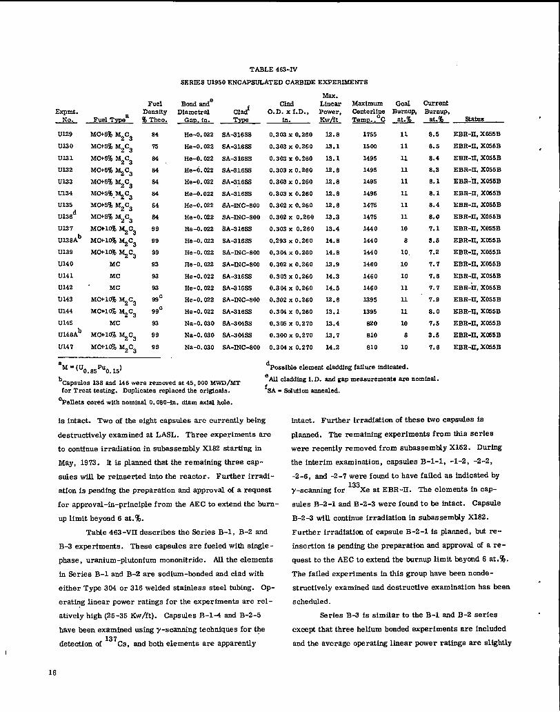
TABLE 463-N
SERKESU1950 ENCAPSULATED CARBIDE EXPERIMENTS
FuelExpmt. Density
Xo. Fuel TVPSa W!!s%
UL?9
u13 o
U131
u122
u133
u134
U195
u136d
UI.37
u138Ab
U139
U140
U141
U142
U143
U144
U145
U146Ab
U147
MC+5% M2C3
MC+5% M2C3
MC+5% M2C3
MC+5%~C3
M(X5% M2C3
MWi%.~C3
MOt5% M2C3
MC+5% M2C3
MC+lU%~C3
‘GIM ‘2C3MCW1O%~C3
MC
MC
Mc
MC+l@fJ M2C3
MC+1O% ~C3
MC
MC+1O% ~C3
MC+1O% M2C3
84
75
84
84
84
84
64
64
99
99
99
93
93
93
99C
99C
93
99
99
BondandeDiametrnl
Gm. in.
He-O. 022
He-O. 022
He-O. 022
He-O. 022
He-O. 022
He-O. 022
He-O. 022
He-O. 022
He-O. 022
He-O. 022
He-O. 022
He-O. 022
He-O. 022
He-O. 022
He-O. 022
He-O. 022
Na-O. 030
Na-O. 030
Na-O. 030
cladType
SA-616SS
5A-31665
5A-31655
SA-016S
5A-21688
5A-31655
SA-INC-800
SA-INC-800
.9A-31655
5A-31688
SA-INC-SOO
SA-INC-800
5A-31688
8A-2 16SS
SA-INC-800
SA416SS
SA4 IMSS
8A-3 Mss
SA-INC-800
a~=(U0.85PU0.15)
bcapstdes 128 and 146 were removed at 45,000 MWD/MTfor Treat testing. Duplicates replaced the origlnale.
‘Pellets cored with nominal O.060-in. dlam axial hole.
Max.clad Linear
O.D. X I. D., Power,in. &&
0.302 X 0.260
0.303 X 0.260
0.302 X 0.260
0.303 X 0.260
0.203 X 0.260
0.303 X 0.260
0.302 X 0.260
0.302 X 0.260
0.303 X 0.260
0.293 X 0.2G0
0.304 x 0.260
0.302 X 0.260
0.303 X 0.260
0.304 X 0.260
0.302 X 0.260
0.31M X 0.260
0.305 X 0.270
0.300 X 0.270
0.304x 0.270
12.8
Isol
13.1
12.8
12.8
12.8
12.8
X3.3
13.4
14.8
14.8
12.9
14.3
14.5
12.6
13.1
13.4
1.2.7
14.2
CenterlineTemp.. ‘c
1755
15m
1495
1495
1485
1495
14’76
1475
1440
1440
1440
1460
1460
1460
1395
1395
830
610
610
Goal CurrentBurnuP, Burnup,
-&K J?&!lL status .
11
11
11
11
11
11
11
11
10
6
10,
10
10
11
11
11
10
6
10
8.5
6.5
8.4
8.9
8.1
8.1
6.4
8.0
7.1
3.6
7.2
7.7
7.6
7.7
7.8
8.0
7.5
3.s
7.6
is intact. Two of the eight capsules are currently being
destructively examined at LASL. Three experiment are
to continue irradiation in subassembly X162 starting in
May, 1973. It is planned that the remaining three cap-
sules wfll be reinserted f.ntothe reactor. Further irradi-
ation is pending the preparation and approval of a request
for approval-in-principle from the AEC to extend the burn-
UPlimit beyond 6 at.%.
Table 463-VII describes the Series B-1, B-2 and
B-3 experiments. These capsules are fueled with single -
phase, uranium-plutonium mononitride. All the elements
fn Series B-1 and B-2 are eodium-bonded and clad with
either Type 304 or 316 welded stainless steel tubing. Op-
erating linear power ratings for the experiments are rel -
atively high (25-35 Kw/ft). Capsules B-1-4 end B-2-5
have been examfned using y-scanning techniques for the
detection of137
Cs, and both elements are apparently
dPossible element clsddfng faflure indicated.
‘All claddfng I.D. and gap measurements are nominal.
‘5A = Salution annealed.
EBR-11, X066B
EBR-11, X056B .
EBR-11, X055B
EBR-11, X055B
EBR-11, X055B
EBR-11, XM5B
EBR-11, X065B
EBR-11, X055B
EBR-11, X05SB
EBR-11, X056B
EBR-11, X055B
EBR-11, X055B
EBR-LI, XOS15B
EBR-”ii, X055B
EBR-11, X055B
EBR-IJ, X055B
EBR-11, X055B
EBR-If, XM5B
EBR-II,X055B
intact. Further irradiation of these two capsules is
planned. The remaining experiments from this series
were recently removed from subassembly X162. Durfng
the interim examination, capsules B-l-1, -1-2, -2-2,
-2-6, end -2-’7 were found to have failed ae fndicated by133
y-scanning for Xe at EBR-11. The elements fn cap-
sules B-2-1 and B-2-3 were found to be fntact. CapsU10
B-2 -3 will continue irradiation in subassembly X182.
Further irradiation of capsule B-2-1 is planned, but re-
insertion is pending the preparation and approval of a re -
quest to the AEC to extend the burnup limit beyond 6 at.%.
The failed experiments fn this group have been nonde-
structively examined and destructive examination has heen
scheduled.
Series B-3 is similar to the B-1 and B-2 series
except that three helium bonded experiments are included
and the average operating linear power ratings are slightly
.
16

TABLE 463-VSER@SU1930ANDU1960ENCAPSULATEDCARBIDEEXPERIMENTS
,
v
.
.
Max.I?uel Bond and clad Linear Maximum Goal Current
Expmt. Density, Dimnetralf~
Cladd O.D. X I.D.; Power, &mterl~ Burnup, Burnup,Fuel TVPOa % Theo Gap, in. Tfle in. U TemD.. C*A Statue
~;;~----------------~---~;-;-;;~--~~;;~------A----------i-o-;------iiiF---------------------------M0+5%~c3 -. 0.304x0.264 . 5 4.6 Exam, 2.12U169 bfC+5% ~ C3 84 He-O. 00’7 SA-INC-800 0.302x0.262 30.0 1935 6 4.5 .Exam, 2.12
U191 MC 92 Na-O. 030 SA+304SS 0.304x0.276 31.7 1148’ 5 4. ‘I
U192 MC
Exam, 2.I.292 Na-O.030 8A-36488 0.305x0.277 31.7 1148 5 4.7 Exam, 2.12
U184 MC+1O%~C3 98 Na-O.030 sA404SS 0.306x0.277 33.1 1122 5 6.0 Exam, 2. u=IJlwi MC+1U%M2C3 98 Na-O.030 sA-i304ss 0.305%0.276 33.1 1132 5 5.0 Exam, 2.12
U197 MCMC% ~C3 98 Na-O. 030 SA-INC-600 0.305x0.277 33;4 llaz 5 5.0 Exam, 2.12
U128 MC+lC% ~C2 98 Na-O. 020 SA-INC-600 0.305x0.277 33.4 1132 5 6.0 Exnm, 2.12
U200 MC+5% ~C3 66 He-O. C418 SA-304SS 0.288x0.260 30.8 2042 5 4.6 Exam, 2.12°
U2”06 MC+5% ~C3 90 He-O. 008 8A+ 16SS 0.288x0.252 31.5 2064 5 4.7 Exam, 2.12
U208 MC+lU% ~c3 97b He-O. 009 5A-21638 0.293x0.257 31.9 1.81s 5 4.6 Exam, 2.X2- — ------------- ----------- -----.-------------- ----------- - ----------- -------- -----.-------- ----- .-— ---------------BU188 MOt5% ~C3 64 He-O. 007 8A-31655 0.304x0.264 30.0 1935 11 8. ‘1 EBR-11, X182
U190 MO+S% ~C3 64 He-O. 007 SA-INC-800 0.302x0. 262 30.0 1835 11 8.8 EBR-11, X182
U189 MC 92 Na-O. 030 SA-304SS 0.305x0.277 31.7 1148 11 8.7 EBR-~, X182
U198‘ol@ ‘2C9
98 Na-O. 020 SA404ss 0.305x0.277 32.6 11.32 11 S.6 EBR-11, X162
U199 Mc+lM ~C3 96 Na-O. 030 SA-INC-600 0.305x0.277 33. s 1132 11 5.0 EBR-11, X182
U201 MOM% qc3 85 He-O. 006 SA-204SS 0.288x0.260 30.0 2042 11 4.5 EBR-11, X182
U207 MC+5% ~C3 90 He-O. C06 9A-316SS O.293x0.257 31.7 2068 11 4.7 EBR-11, X162
U209‘&lM %c2--_:7b ‘::!:!!?: ‘A+16SS !~-YY-:[:-__:!-:___-:-w 2:--_.::!----::-:::::-::---------------------
U185 M&l@ M2C3 86 He-O. 011 SJQ?16G?3 0.304x0.264 30.0 2195 3 3.0 Exam, 1.’7
U166 MOtlC% M2C3 96 He-O. 011 8A-21655 0.304x0.264 30.0 21.95 3 2.0 Exam, 1.7
U202 bfc+5% ~ C3 85 lie-O 5A-31655 0.2 G9x0.251 31.7 IZ70 3 2.8 Exam, 1.7
U203 MCY5% ~c3 85 Ho-O 5A-31655 0.268x0.252 31.4 1260 3 2.6 Exam, 1.7
U204 MC+l@% ~C3 97b He-O 5A-3 16SS 0.266x0.246 32.2 1131 2 2.9 Exam, 1.7
U205 b‘&lW ‘2C3
0.284x0.248----------------------:: --------: -------:::::::------s----------:1::----.-1:::-----:----:::----~-::-:::--U260 MC+lG% ~C3 96 He-O. 015 20CW-316&9 0.296x0.264 34.1 2590 12 ---
EBR-11, IM-U261e MCWl@%M2C3 96 He-O. 015 5A-31855 0.290x0.260 34.1 2590 12 ---
Iassigned
U262 rdC+lc%~c3 97 He-O.01.5 SA-INC-600 O.290x0.260 24.1 2590 X2 --
aM = (U. 65Pu0. ~)d
.3A = Selution annesle~ 20CW = 25% cold-worked.
bCored pellets with nemimd O. 080-in. diam sxfal hole. ‘Eddy current test at EBR-11 indicates capsule bond dfscontInaity.
cElemeti cladd~ for 194 end200 has faikd ‘All elsddfng I.D. and gap meeeuxements are nominal.
higher. Gamma-scane made at EBR-11 for 133Xe in&ca-
ted that the four sodium-bonded elements have failed,
while the three helium -bonded elements have not failed.
Nondestructive examination of the failed elements is cur-
rently uncler way. The three unfailed helium-bonded ex-
periments are to continue irradiation in subassembly X182
starting in May, 1973.
The Series U51OO singly-clad experiments are de-
scribed in Table 463-VIII. In thfe group, either single-
phase or two-phase carbide fuel is sodium bonded to Type
304 or 316 stainlees steel or to Incoloy 800. fn seven of
the elements, a shroud is incorporated primarfly to test
the retention off uel fragrnents by close f ittiig tubes. A
secondary objective of the shroud is to study the effective-
ness of the shroud alloy as a carbon getter. These ele -
ments will be irradiated in subassembly X156 starting
with run 63 fn May, 1973. The first interim examination
will be made at a burnup of 2.5 at.%.
17

TABLE 463-VI
SERIES WF ENCAPSULATED CARBIDE EXPERIMENTS
Max.Fuel Bond and clad Linear
Bxpmt. Density, Diametral Cladb O.D. X I. D., Power,No. Fuel Tvmea * Gap. in. TYPS in. J@&
Maximum Gosl CurrentCenterl& BurnuP, BurouP,Temp., c-d Status
.
.1075 10° 6.0 EBR-11, Un-
aseignod
Exam, 1.7
EBR-11,X162
EBR-11,X163
EBR-11, Un-assigned
Exam, 2.1
EBR-11, Un-assigned
EBR-11,X182
W3F MC+6-15% ~C3 91 Na-O. 025 5A-31683 0.900x0.276 27
W4F MC-+7-17% ~C3 9S
W5F Mot7-ic% ~c3 88
Na-O. 027
Na-O.010
8A-31629 0.300x0.276
SA-316S 0.260x0.230
28
20
1100
975
6 6.1
6 2.9
W617 MC+9-10% ?d2C3 89
W7F MC+5% M2C3 89
Na-O. 011 SA416SS 0.251x0.231 20 975 6 2.9
10° 6.027 1075Na-O. 027 20 CWi316SS 0.300x0.276
W8F MtX3-6% ,~C3 93
W1OF XVIC+O-3%~c3 88
W12F MC!-19-24% M2C3 95
Na-O. 025
Na-O.012
20CW-316SS 0.300x0.276
SA+ 16SS 0.251x0.231
28
20
1100
975
8 6.6
109 6.9
5A-31629 0.261x0.231 21 1000 6 2.8Na-O. 013
aM=U0.8m0.2
b6A = Solutionsnnealed,20 CW= 20%cold worked
‘Original goal burnup was 8 at.%. New AIP requestfor furtherirradiationin preparation.
Possible design parameters for a new group ofThe C-5 and ON-1 series of singly-clad experi-
ments are described fnTable 483-IX. Single-phase nitride
fuel is sodium bonded to 20% cold-worked Type 316 stain-
less steel cladding in all of tbe fuel elements in this group.
Profilometry measurements of the C-5 series elements
have been made uetng the same equipment that will be used
for the postirradiation examination. Shipment of selected
elements to EBR-11 is pendf.ng LASL review of the experi-
ments from a quality assurance standpoint.
The O-N1 series of singly-clad experiments is
similar to the c-5 series. The elements are fueled with
‘U0.8R0.2) N which is sodium bonded to 2Cf%cold-worked
Type 316 stainless steel cladding. Three elements have
been rejected because of large fuel chips in the sodium
annulus. The diameters of the elements have been mea-
sured on the same profilometer that will be used after ir-
radiation. The status of shipment of these experiments
to EBR-11 is the same as for the C-5 series. Four of the
fuel pfns from Series O-N1 will be irradiated with fifteen
pins from Series C-5.
experiments, Series K-4, have ixxm described in previous
quarterly reports. The final design of this subassembly
has been deferred pending the analysis of the irradiation
experiments currently being examfned.
In addition to the experiments described above,
two nitride fueled thermal irradiation experiments from
ORNL (43N1 end 43N2) will be examfned. Results and
status will he reported in future reports.
Engineering Teat Plans have been prepared and
approved in order to satisfy the Quality Assurance re -
quirements for the irradiation and examination for the ex-
periments in the K1, K2, IC3, U1300, U1950, U193O,
U1960, U51OO, B-1, B-2, B-3, C-5, and O-N1 series of
tests.
A major effort has been expended in the overall
evaluation of all of the high performance irradiatim ex -
periments under LASL direction. AU available data on
each experiment bas been cataloged and evaluated with
respect to both technical characterization and quality
control completeness. An overall evaluation for each
.
.

.
./
,
TABLE 463 -VII
SERIES B-1, B-2 AND B-3 ENCAPSULATED N2TRIDE EXPERIMENTS
Max.Fuel Bond and clad Linear Mo-ximum Goal Current
Expmt. Density, Diametrel Clede O.D. xI.D., Power, centerline Burnup, Bumup,& Fuel Tvw % Theo GaP, in. TYlx3- in. .!@& Temp. .“c Q&l A status
'----------------------------------------------------&ties B-l------------------------------------------------B-l-1 (U
O.8m0.2)N80 Na-O. OIS 6A-2 04ss 0.290x0.250 27.9 1125 5 6.6 Exam, 1. 7b
B-1-2 (Uo. Jhao02)N 81 Na-O. 018 SA-304SS 0.290x0.250 27.1 1135 9 6.9 Exam, 1. ‘7b
B-14 (U. &oa2)N 85 Na-0, 013 SA-304S9 0.290x0.250 28.6 1150 lof 9.0 Exam, 1.7C'-------L-------------------------------------Sties B-2 —-—---------------—-—----~—----—------------B-2-1 (Uo. #uo.2)N 62 Na-O. 021 5A-31668 0.21SX0.275 2’2.’1 1330 10 6.3 EBR-11, un-
assigned
B-2-2 (Uo. 6Pu0.2)N 82 Na-O. 020 6A-31666 0.316x0.275 32.5 1230 9 8.2 Exam, 1. ?
B-2-3 (uo. 8Pu002)N 81 Na-O. 020 3A-31639 0.315x0.275 32.4 1230 X2 6.9 EBR-11, X163
B-2-5 (Uo. #Uo. 2)N 76 Na-O. 028 6A-316fiS 0. S16x0.284 32.4 1230 la 3.0 Exam, 1.7°
B-2-6 (U. Epuo 2)N 82 Na-O. 021 6A-31666 0.316x0.295 36.6 1330 6 6.2 Exam, 1.7b. .B-2-7 (Uoa8Pu0,2)N 63 Na-O. 030 5A-31655 0.316x0.295 36.7 1230 12 6.1 Exam, 1. ?b
'------------------------------------------SerIes B-3--———----——-----—--—-—-----—----—------=--B-3-2 (Uoa8Pu0.2)N 88 Na-O. 008 5A-36468 0.316x0.264 37.7 1250 9 3.1 Exam, 2.7
B~-3 (Uo. 6Pu0.2)N 91 Na-O.010 2A-26438 0.316x0.264 36.9 1260 E? 3.1 Exam, 1.7b’d
B-34 (Uo. 8Pu0.2)N 94 Na-O. 013 5A-3 MSS 0.316x0.264 98.9 1280 la 3.1 Exam”, 2. 6b
B-3-5 (uo. Epuo, 2)N 90 Na-O. 010 aA-304&s 0.316x0,295 41.5 1310 6 3.1 Exam, 2.7b
B-3-6 (u0.8R0.2)N 95a He-O. 005 SA-304SS 0.3 Mx0.275 34.2 1925 6 3.0 EBR-11, X163
J34-7 (uo. Epuoo2)N 63 He-O. 005 8A-3 04ss 0.315x0.275 34.2 Ui25 6 3.0 EBR-11, X133
B-3-8 (Uo- 6Pu0.2)N 9Oa Ha-O. 005 SA-204SS 0.315x0 .2’75 32.4 1875 6 2.9 EBR-?, X163
hellets are annular with a O. O?O-in. diem axial hale. %Jondestructive examination completed. Capeule etored for Possiiieb
Element elsdding fsflure tndicatsd. irradiation of fafled element.
cAvai.kble for further irradiation. ‘Cladding is welded tubing. 8A= Selutlon annealed.fOrlginsl goal bumups were 3 to 5 at.%. New AIP request forftiher irradiation fn preparation.
series (except the O-N1 series) from a quality control
standpoint will be completed during the first part of next
quarter. The transfer of information f rom ORNL, the
original experimenter, is stfll incomplete for the O-N1
series; consequently that evaluation will necessarily take
somewhat longer than for the other series. A summary
report of the evaluations and LASL recommendations will
be issued for RDT review.
c. TREAT Ii?radiation Teeting(J. F. Kerrisk, D. G. Clifton, R. E. Alcouffe)
In order to assess the behavior of (U, Pu)C and
(U, Pu)N fueled elements under fast reactor accident con-
ditions, transient irradiations will be conducted in the
TREAT facility. Investigations will be carried out on
both irradiated and unfrradiated fuel pins to determine
(1) the threshold power levels at which damage or failure
occurs, (2) the effect of bond and clsddfng defects, end
(3) the failure propagation mechanism in multipin assem-
blies.
1. Series UL Tests. A cooperative effort has
been carried out with Gulf United Nuclear Fuels Corpor-
ation in the area of TREAT teWng. A series of four
tests, designated LABL Series UL, wfll determine the ef -
feet of irradiation on the behavior of helium and sodium
bonded advanced fuel elements (fabricated by GUNFC) un-
der possible LMFBR accident conditions. Table 463-X
describes the fuel elements and test objectives. LASL
has assumed complete responsibility for these tests in
fiscal year 1973.
a. Test LASL-UL-1. Test LASL-UL-1 was
performed November 16, 1972. The TREAT capsule
from thfs test has been returned to LASL and the poatir-
radiation examination has been started. At present, only
rsdfographe of the TREAT capsule have been reviewed.
No indication of fuel element failure has been seen.
b. Teat LASL-UL-2. Test LASL-UL-2 (TREAT
transient number 1495) was performed on February 20,
19

TABLE 463-VIII
SERIES U51OOSINGLY CLAD CARBIDE EXPERIMENTS
Ms...LinearPower,
J@&
95.8
Bond endbDiamctral
Gap, in.
Na-O. 018
Clad”clad
O.D. xI.D.,in.
0. S10s0.281
GoalBurnuP,
J!!&
6
9
6
9
CurrentBurnup.A txatus
o EBR-11,X156
o EBR-JI,X156
o EBR-11,X166
Expmt.&
U241
I?uclDensity,
-
92
ContcrlineTemm. ‘c
1175
1175
1150
11’15
.
.
Fuel Tyvea
MC
TYIM
5A-2 04SS
U242 SA-20L9S O.31OXO.281MC 92 Na-O. 017 35.8
33.8
35.8
33.8
U243
U244
U245
92
92
91
92
Na-O. 031
Na-O.017
Na-O. 033
N&-O. 017
8A-204s2
5A-26458
SA43MSS
0.31 CX0.281
0.310s0.281
MC
MC
MC
MC
o EBR-11, X158
o EBR-KI, X156
o EBR-11, X156
o EBR-11, X&6
O.31OXO.281 U50 la
O.31OXO.281
O.31OXO.281
O.S1OXO.281
36.4
9S.8
36.4
1190
1150
1140
U246 SA-318SS
U247
U248
U249
5A-21688
5A-31885
SA-INC-800
MC
MC
MC
MC
92
91
92
91
Na-O. 032
Na~O. 033
Na-O. 017
la o EBR-11, X156
o EBR-11, X156
o EBR-11, X156
o EBR-11, X168
0.309x0.281 38.4 lslo
1145
1145
6
8
E?
98.4
36.4
36.4
22.8
33.8
34.0
33.5
U25 o Na-O. 022 SA-INC-800 0.302x0.281
O.31OXO.281
O.31OXO.281
O.31OXO.281
U251
1.!!52
U253
92
92
92
SA-204S2
5A-3 04SS
sAi31Mss
MC
MC
MC
Mc
MC+l@ M2C3
M<% ~C3
MCYIU% M2C3
Na-O. 021
Na-O. 024
Na-O. 024
1140 Is o EBR-11, X156
o EBR-11, X166
o EBR-11, X158
o EBR-11, X158
Is
ls
12
1145
1140
1140
0.310%0.281
0.302x0.281
0.308x0.281
U254
U256
U257
U258
92
95
95
Na-O. 024 8A-3 Msa
5A-2 046S
SA-INC-800
Na-O. 024
Na-O. 024
Na-O. 024
0 EBR-11, X156
o EBR-XT, XX%
o EB13-11, X16d
has
1145
1150
Iz
6
ls
95 SA-304SS O.31OXO.281 33.5
MC+1O% M2C3 Na-O.024 SA-INC-SOO 0.309x0.281 34.6U359 95
%C = U. 85PU0 15. bElements U-252, -253, -254, -256, -257, -258, end -259 have shrouds N 0.0035 In. th.fck made from V, Fe,304SS, 304SS, V, Ta, 304SS, end 304SS, respsotively. The shrouds are slotted.
oSA= Solution healed
1973. A preliminary review of the capsule temperatures
indicated that the test was performed as requested. The
TREAT capsule from this test has been returned to LASL.
c. Tests LASL-UL-S and LASL-UL-4. The ss -
sembly of the inner capsules for tests 3 and 4 of the UL
Series was done by GUNFC up to the pofnt of insertion of
the fuel elements into the inner capsules. Sinoe the fuel
elements were preirradisted in EBR -II, the completion of
the assembly of the inner capsule and the assembly of the
inner capsules into the TREAT capsules requires hot cell
facilities. LASL, f.n conjunction with RDT, has arranged
for the completion of the assembly by the Radiometellurgy
Group of Hanford Engineering Development Laboratory
(HEDL). A purchase order coverfng the assembly work
has been written to HEDL. Additional welding samples
required by HEDL for weld development have been fabri-
cated and shipped. A quality sasursnce plan covering the
assembly and inspection of the capsules, the tests, and
the postirradfstion examination bas been prepared and
submitted to TREAT for approval.
20
2. Series 1 Tests. A group of eight tests using
LASL fabricated fuel elements has been designated LASL
Series 1 teats. The tests are designed to determine if
any significant safety related behavioral proklems exist
for sodium bonded, stainless steel CM (U, Pu)C and
(U, Pu)N fuels by defining failure thresholds and the types
of failure experienced by these fuels. Table 463-XI sum-
marizes the test parameters end objectives. Apprcwel-
in-principle has been received from the AEC for this se-
ries of tests.’
An Engineering Test Plan, an Inspection and Test
Plan, and detail fabrication and assembly drawfngs have
been completed for the initial tests of this series. Due to
a reduction in funding, work on this series of tests has
been postponed.
3. Fuel-Coolant Interaction Tests. At the re-
quest of RDT, sn investigation into the feasibility of per-
forming fuel-coolant interaction tests with high perfor-
mance fuels was started. The initial objective of these
tests would be to study the manner in which molten

TABLE 463-XX
~RIES C-5 AND O-N1 SINGLY CLAD NITRIDE EXPERIMENTS
Max.Fuel Bond and clad Linear Maximum Goal Current
E.xpmt. Density, Diametral Clada O.D. X I.D+ Power, c-enterl~ BurnuP, Burnup,~ Fuel TWM f?&!E!L GaD,in. Twe in. && Temp.. c-a Status------------------------------------------------- Series C-5------------—— _—_— ------ —-_------- —--- ——. .C-5-1 (Uo. #uoJN
C-5-2 (Uo. #uo.2)N
C-5-3 (Uo. #Uoo .JN
C-54 (Uo, J% ~. .JN
C-6+ (Uoo#Uo.3)N
c-6-6 (Uo. 6Pu0.2)N
C-5-7 (Uo. #uom2)N
C-5-8 (Uo. SpuooJN
C-5-9 (Uo. 6Pu0.2)N
C-5-1O (Uo. 6Pu002)N
C-5-11 (uo. 8Pu0.2)N
c-5-12 (Uo. ~Pu ~JN
C-5-13 (Uoo~Puo. JN
C-5-14 (UO ~puo JN
C-5-15 (Uo: 8Pu002)N
C-5-16 (Uo. ~Puo.2)N
C-5-17 (Uo. 8Pu0.2)N
C-5-18 (Uo- 8Pu0.2)N
C-5-18 (Uo. 8Pu0.2)N
C-5-2 O (UU ~Puo 2)N. .
--------------------------
93
93
94
95
95
93
94
94
94
94
94
84
98
96
85
96
86
94
84’
95---------
NATO.020
Na-O.020
Na-O. 020
Na-O. 021
Na-O. 020
Na-O. 021
Na-O. 020
Na-O. 020
Na-O. 020
Na-O.020
Na-O.020
Na-O. 020
Na-O. 020
Na-O. 030
Na-O. 030
Na-O. 030
Na-O. 020
Na-O. 021
Na-O. 021
Na-O. 021
20 CW-316SS
20 CW-316S8
20CW-316W
20 CW-216S.S
20 CW-316S2
20 CW-316S3
20 CW-216SS
20CW416SS
20 CW-3163S
20 CW-216SS
20 CW-218SS
20 CW-216SS
20 CW-316SS
20 CW-316SS
20 CW-318SS
20 CWi316SS
20 CW-216SS
20CW-316SS
20 CW418SS
20CW-316SS
O.31OXO.28O
O.31OXO.2SO
O.31OXO.26O
O.21OXO.26O
O.31OXO.26O
O.31OXO.28O
O.31OXO.26O
O.31OXO.26O
O.31OXO.28O
O.31OXO.28O
O.31OXO.26O
O.21OXO.28O
O.31OXO.28O
O.31OXO.28O
0.310s0.280
O.31OXO.28O
O.31OXO.28O
O.31OXO.28O
O.31OXO.26O
O.31OXO.28O
-- —
-- --
.- --
33.2 7U3
--––-~e---–-
33.2 720
23.7 724
32.7 623
23.5 851
32.6 625
33.4 as
22.5 644
32.1 623
32.0 711
32.1 642
------spare ------,.
-- --
32. ii 645
33.0 649
32.4 624
--
U
M
Is
l!f?
12
X2
12
U.
12
u
12
ls
Is
--
-is,
12
12
0
0
0
0
0
0
0
0
0
0
0
0
0
0
0
0
RejectD’cb, ORejeotb, ORejeot,
At LAsLd
At LASLd
At LASLd
At LASLd
At LASLd
At LAsLd
At LASLd
At LASLd
At LASLd
At LASLd
At LASLd
At LASLd
At LASLd
Rejectc
At LASLd
At LASLd
At LASLd---------— --------- SeriesO-N1-----------------------------------------------------
O-N1-1 (Uo. *Pu0.2)N 90 Na-O. 020 20 CW-316SS O.31OXO.28O 32.9 648 12 0 At LASLd
O-N1-2 (U0.6m0.4N 90 Na-O.020 20CW-316SS 0.31 CX0.280 -- -- Rejectb
O-N1-3 (Uo. 8puo.2)N 90 Na-O.020 20 CW-316SS 0.31&0.280 32.6 717 X2 o At LASLd
O-N1-4 (U0.8PU0.2)N 90 Na-O. 020 20 CW-3162S O.31OXO.28O 22.6 717 12 0 At LASLd
O-N1-5 (Uo. 8Pu0.2)N 90 Na-O. 020 20 CW-316SS O.31OXO.28O -- ~-- -- Rejectb
O-N1-6 (Uo. 8Pu0.2)N 89 Na-O. 020 20 CW-216SS O.31OXO.28O -- — -- Rejectb
O-N1-8 (Uo.6PU0.2)N 90 Na-O. 020 20 CW416S3 O.31OXO.28O 33.1 718 12 0 At LAsLd
% OCW= 20%cold worked bchips in bond CAfrin plenum
carbide or nitride fuel interacts with liquid sodium, and to
measure the pressures generated and the conversion of
thermal energy to mechanical energy due to the inter-
action. The fuel-coolant interaction tests performed on
oxide fuels were reviewed. Due to a reduction in funding,
fuel-coolant interaction work on high performance fuels
wfJl not be pursued at the present time.
m. ANALYTICAL CHEMISTRY
1. X-Rav Fluorescence Spectrometric Determin-ation of Ta .III stainless Steel(G. B. Nelson, J. M. Hansel, E. A. Hakkila)
dQA evaluation in progress
Chemical characterization of stainless steels for
FFTF Program applications requires reliable measure-
ments of several specified impurities including Ta. Mod-
ifications of an existing solvent extraction method for
separation of Ta at low concentrations from stainless
stee13 permits final measurement by en x-ray fluores-
cence method. This separation invalves extraction of Ta
from a 6~ H2S04 -l&l RF mixture, followed by a second
extraction from 6X H2~4-0. 4~ HF. Previously, rela-
tive standard deviations were reported to he 4.6% for de-
termining 500 or 1000 pg (1000 or 2000 ppmj of Ta in
500 mg samples, with a limit of detection of approximately
1 21

TABLE 463-X
LASL SERIES UL TESTS
T’EsrLASL-UL-1 LASL-UL-2 LASL-UL-2 LASL-I,JL-4
Fuel Elexbenta 263 (138 A) 264 (146 A) 266 (133) 266 (146)
Fuel Materialb 90 Vd% ( Uoo~puoo # + 10vd% (Uo.65h0. 15)2cS
Fuel Pellet 0.246 0.240 0.246 0.240O. D., in.
Bond Materiel He Na He Na
Bond Thickness 0.005 0.015 0.005 0.015(Radial), in.
(kid Material 316S8 304ss 31668 S04SS
CladThickness, fn. 0.022 0.015 0.022 0.015
Smear Cenaity, 90 77 90 77% Theoretical
Fuel CehunnLength, in. ---------------------— 12.75 * 0.125 ----— ------------------------
Burnup, o 0 45,000 45,000MWD/MTMO
Test Objective Fuel Meltfug Fuel Meltfng Same Trsaaient Same Trsnaieates 263 aa 263
?Fuel element numbers reassigned by Gulf United. Old numbers shown in psrentbesea.b 235UUranium enriched to 6% in .
‘Irradiated fn EBR-If at 10 to 15 Kw/ft fn subassembly X055.
TABLE 463 -XI
LASL SERIES 1 EXPERIl@NTS
Fuel~ Materiela
1A-1 (UO #uo.2)c
1A-2 (U0.8PU0.2)C
lB-1 (Uo. *PU0.2)C
lB-2‘UO. 8W0.2)N
lB-3 ‘UO. 6PU O.&c
1B4 ‘U0.8W0.2)N
lC-1 (UOJ+$3.2)C
1c-2(“o. #’’o.2)N
TREAT b
Z!?z!&z Trsnaient
o Fast
o slow
o Fast
o Feat
o 610w
o 610w
t% c
6% c
Teat Obiective
Na bond eje~hn-incipientfuel meltfng
Same as 1A-1
5U% fuel melting
Same as lB-ld
Same as lB-I
Same se lB-ld
Same sa lB-1
Same as lB-ld
aThe fuel will b pclleta, contained in 0.310 in. o.d. by 0.012 in. wall 316 stafnlesa steelcladding at80% smear density. The uranium is enriched to 93% fn 235U.
bFast trwsients till depait energy in time pericds of the order of 1 sec. while slowtransients will be on the order of 10 sec.
cThe type of transient to be used wffl be determined hy the results of the unlrradistedelement tests.
‘Since (U, Pu)N does not melt, but decomposes to metal and nitrogcm, the test objectivesaro described in terms of the energy required to produce a given melting in (U, Pu) C.
.
<
I
22

v
4
3.3 #g (7 ppm). During this report period the precision
were measured for Ta concentrations between 10 and 100
Kg in 500 mg samples (Table 463-XII).
TABLE 463 -XII
PRE CISfON OF X-RAY SPECTROMETRICDETERMINATIoN OF Ta IN STAINLESS STEEL
(500 mg Samples)
Ta RelativeAdded, Number of Standard Standard
U$z Determinations ~eviation. UK Deviation, %
10 10 3.2 32
25 9 3.7 15
100 8 11.9 12
Triplicate analyses of two National Bureau of
Standards SRM samples indicated that the measured pre-
cision were accurate. There was a small negative bias
in the method which was eliminated by chemical calibra-
tion. Measured Ta contents were 330 + 21 ppm in one
sample reported to contain 360 ppm, and 2230 * 160 ppm
in a sample certified at 2300 ppm Ta.
The effects of various elements that may be present
in stainless steel are being tested to determine possible
interferences. Up to 0.5 wtyo of Mo was shown to have no
effect, and tests of other elements are uncler way.
2. Coulometric Titrations of Pu and U(N. Fawcett)
In the coulometric titration of U in the presence of
Pu, a pre-electrolysis at i-O. 085V vs. the saturated calo-
mel electrode (SCE) is sufficient to oxidize HgO to Hg+ if
even trace quantities of Cl- ion are present. At the poten-
t.fal of the final electrolysis, whfch is -O. 325V vs. the SCE,
Hg+ is reduced to HgO. It is imperative to avoid contami-
nation of the sample solution with Cl-, or electrcJYsis of
Hg+ to HgOwill contribute to the current during the final
electrolysis of U(IV) to U(VI). Furthermore, if there is
more than a trace of c1 - present, Hg2C12 precipitates on
the mercury surface forming a film which decreases the
rate at which soluble ions are electrolyzed.
It appears that the most likely source of chloride
contamination is the SCE which is almost universally used
as a reference half cell. Even though the SCE is isolated
from the titrant by an intervening 1~ F$ S04 salt bridge,
Cl- leaking from the fiber junction in the SCE may
eventually diffuse through the salt bridge and into the
working electrode compartment.
To avoid Cl- contamination, the SCE was replaced
with a Pb(Hg)/PbS04 reference half cell. The lead sul -
fate electrode (LSE) is commercially avaflahle and is as
stable and long-lived as the SCE. The supporting electro-
lyte for the LSE can consist of ~ H2S04, making the
chemical potential of sulfate ion the same in the reference
electrode, the Vycor tube salt bridge, and the working
electrode compartment. Use of the LSE in titrating
known quantities of U has proved satisfactory.
Coulometric determination of Pu(VI) by reduction
at Pt to Pu(III) followed by subsequent oxidation to Pu(IV)
does not proceed satisfactorily in aqueous HCl at room
temperature. Reduction of Pu(VI) on Pt at +0. 31OV vs.
the SCE required more than 1 h in ~ HC1 at 25°C. More
negative potentials, up to the point of ~ evolution, were
also ineffectual. As the HCl electrolyte effectively re-
duces interference caused by small amounts of Fe impur-
ity, conditions were investigated to produce satisfactory
titrations of Pu in HCl.
Warming the sample solution to approximately 50°C
was found to produce a much more rapid reduction. Thus,
5.759 mg of Pu(V~ in 1~ HCl at +O.31OV was reduced to
Pu(III) in less than 30 min as fndicated by recession of the
current to a background level of 30 pa. Subsequent oxida-
tion to Pu(IVj at +0. 86V and at 25°C resulted in a titer of
5.758 mg Pu after subtraction of a measured blank cor-
rection. For solution samples not adversely affected by.“
elevated temperature, warming the solution during the pre-
reduction step may make it possible to titrate hydrochloric
acid solutions of Pu(V~ without preliminary chemical re-
duction of the Pu(VI). Further work is in progress to ver-
ffy this observation.
Iv. QUAL~Y ASSURANCE
~~e~ ~rg~aga~QW Procedures for fuel prepara-
tion are being revised. A traveler system is being pre-
pared to document all processing and inspection data dur-
ing the preparation and characterization of the material.
The calibration of instruments has continued and
records are being made for these instruments. Quality
23
Assurance Procedures for instrument calibration have 2. R. D. Baker, ‘Quarterly Progress Report on the
been prepared, approved, and are being used.Advanced Plutonium Fuels Program, July 1 toSeptember 30, 1972, ” Los Alamos Scientific Lab-
~tgel_Rig ~aJbgig~ign~ Procedures for inspection oratory Report LA-6 106-PR (1972).
and overcheckfng of items have been prepared and the fn-3. G. R. Waterbury and C. E. Bricker, Anal. Chem.
spe ction and overcheckfng are fn process. A traveler sys - 23 1474 (1957).
tern to provide material and component control is being
prepared.
Archive and material storage facilities meetfng
quality assurance requfrementa are being prepared. Items
are being stored, identified and provisions are being set
up for inventory control.
Dummy fuel elements were fabricated, fnspected
and shipped using quality assurance procedures, reviews,
and documentation.
EBE-B lrza@LaUcn_TSs~ Engineering Test
Plans have been prepared for each series of irradiation
experiments. The postirrsdiation examination requests
are based on the requirements of these Engineering Test
Plans .
Files and data packages are being prepared for the
retention of quality assurance and technical information
relating to the EBR-11 tests and the post irradiation exam-
inations.
An audit by the Quality Assurance Msnager was
conducted of the records and procedures for EBR-11 Test-
fng and an audit report was written.
‘lJ~E_A~J~r&d~a&ign_T_e@@~ An Engfneerfng
Test Plan has been prepared for the Serfes 1 TREAT
tests. Procedures for TREAT f abdication, and material
inspection and over checking have been prepared.
Welding samples for work at HEDL were fabrica-
ted, inspected and shipped using quality assurance pro-
cedures, reviews, and documentation.
An audit of the TREAT Irradiation Testing was
conducted by the Quality Assurance Manager and an audit
report was written.
v. REFERENCES
1. R. D. Baker, ‘Quarterly Status Report on the Ad-vanced Plutonium Fuels Program, April 1 toJune 30, 1972 and Sfxth Amual Report, FY 1972, ”Los Alamos Scientific Laboratory ReportLA-5062-PR (1972).
24

*
.PROJECT 472
ANALYTICAL STANDARDS FOR FAST BREEDER REACTOR OXIDE FUEL
Person tn Charge: R. D. BakerPrincipal Investigato~ G. R. Waterbury
I. INTRODUCTION
Necessary to the development of the high quality
fuela and control rods required by the LMFBR program
are highly reliable analytical methods for the chemical
characterization of the source materials and the pellet
products, and for the measurement of burnup and fission
products on irradiated fuels. Objectives concerned with
ensuring the production of these htgh quality reactor ma-
terials are: (1) the continued preparation of carefully
characterized calibration materials for the various ana-
lytical methods, (2) the preparation of quality control
samples used for surveillance of analytical chemistry
laboratory operations during periods of production, (3)
contfnued assistance and guidance of quality assurance
programs for chemical specification sampling and analy-
sis, (4) the development of more reliable methods of
chemical analysis with emphasis on O/M measurement,
(5) the preparation of continuously updated compilations
of analytical methods f or these materials, and (6) the
analysis, as a referee laboratory, of those samples tn
dispute between a vendor and a purchaaer. For the im -
mediate future these objectives are centered on the FFTF.
Later they will be extended to the LMF BR demonstration
and large production plants.
Objectives concerned with irradiated LMFBR fuel
examination are: (1) the development of burnup methods
based on conventional mass spectrometry measurements
and later by spark source mass spectrometry; (2) the de-
velopment of faster burnup methods using them ical
analysis techniques; and (3) start development of analyt-
ical methods for the determination of gases on pre and
poatirradiated fuels and control rod absorber materials
to provide data on gas retention properties and cladding
stability.
If. ANALYTICAL CHEIvffSI’RY PROGRAM FOR BORONCARBIDE
A program equivalent to that established for the pro-
duction of FFTF mixed oxide fuel is in progress for the
production of FFTF boron carbide pellets.
A. Status of Analytical Methods and Qualification ofAnalytical Laboratories(J. E. Rein, W. H. Ashley, G. R. Waterbury)
Nitrogen, probably as BN, has been found as a sig-
nificant impurity in various manufactured lots of B4C.
For this reason, HEDL plans to add to the specifications
a maximum acceptable content for nitride N impurity in
the B4C pellets to be manufactured for the FFTF.
Aa a high priority task, HEDL and LASL will coop-
eratively recommend an analytical method for the deter-
mination of nitride nitrogen in B4 C that will be made avail-
able to the industrial companies. To expedite the issuance
of this methcd, HEDL and LASL exchanged descriptions
of their present state-of-the-art methods. The desirable
features of each were selected and HEDL started writing
a recommended method that included these features. (A
discussion of the LASL method is presented in Section II.
D below. ) To evaluate the reliability and status of this
25

#recoin mended method when used in different laboratories,
the industrial companies, HEDL, and LASL will analyze
a test lot of B4C pellets, using prepared blends to csli-
brate the methods.
B. Preparation of Calibration Materials and QualitvControl Samples(J. V. Pena, H. J. Kavsnaugh, J. E. Rein)
On a high priority basis, LASL is preparing a se-
ries of calibration blends for nitride N in B4C. This se-
ries consists of five powder blends using starting materia-
ls of well-characterized BN and low-nitrogen-content
B4C. Sufficient amounts are being prepared for the im -
medtate laboratory evaluation and for future use by ven-
dor and HEDL laboratories during production of B4C pel-
lets for the FFTF.
Three lots of B4C pellets, supplied by HEDL, are
being characterized for nitride nitrogen content. If prov-
en satisfactory relative to nitrogen levels and homogene-
ity, these lots will be packaged and used as the quality
control samples for the FFTF Quality Assursn ce Program.
c. Status of RDT Standards(J. E. Rein, W. H. Ashley, O. R. Simi,G. R. Waterbury)
RDT FII. -2, ~!Aualytical Chemistry Methods for
Control Rod Absorber Material, ” reviewed by RDT, is
being revised by HEDL to incorporate recommended revi-
sions. A draft of the revised document is being reviewed
at LASL by all contributors.
D. Studies and Improvements of Analytical Methods(R. E. Perrin, T. K. Marshall, A. Zerwekh,G. E. Meadows, A. L. Henicksman, C. H. Ward,W. H. Ashley, and R. G. Bryan)
1. Determination of Nitrogen. The evaluation
of the separation of nitride nitrogen from B4C by caustic
fusion and then titration of the evolved NH3 with acid has
shown the need for several modifications to improve the
reliability of the measurement: 1. Substitution of a sil-
ver crucible liner for the original nickel liner to eliminate
formation of unwanted nitrogen compounds that cause low
results. 2. Substitution of lithium hydroxide monohy -
drate (LiOH oH20) for NaOH as the flux. 3. Addition of a
water bubbler to the gas pretreatment apparatus to supply
the moisture needed to give complete conversion of evolved
N to NH3. 4. Specification of a schedule for heating the
sample slowly to avoid violent early reactions that may
26
spatter sample and flux into the cooler parts of the tube.
Following these modifications, five portions of a BN sam-
ple were analyzed. The recovery of N was 99.3%, assum-
ing theoretical stoichiometry of the BN, and the relative
standard deviation was O.06%.
An independent method for the N determination was
developed in which the BN and B4C were completely dis-
solved in 80% ~S04 in a se~ed) fused-s~ca tube at
3 ‘70°C. Liffle or no residual gas pressure remsined in
the cooled tubes. An sliquot of this solution was made
strongly basic, and the N was separated by distillation as
NH3 which was titrated with standard acid. Seven por-
tions of the previously analyzed BN were analyzed by this
method with an average nitrogen recovery of 99.3% and a
relative standard deviation of O.14%.
The basic fusion and the sealed-tube acid dissolution
methods also were oompared by repeatedly analyzing the
same lot of B4C. The average of seven determinations of
the N by the fusion method was O.71% N with a relative
standard deviation of 1%; the average of six determinations
by the sealed tube dissolution method also was O.71% with
a relative standard deviation of O.6%.
Additional work on the LiOH fusion and the sealed
tube dissolution is needed to determine the effect of parti-
cle size variations. In particular, the possibility of
sealed tube dissolution of unground boron carbide is in-
triguing because of the application to the assay of boron.
The measurement of total N (nitride N PIUSad-
sorbed N) also was investigated. The usual Dumm tech-
nique was found tmbe satisfactory for this purpose. In
the Dumas analysis the sample is mixed with CUO, burned
in an atmosphere of pure C02 in a tube containing Cu and
CUO, and the N is measured volumetrically after the rest
of the gases are adsorbed in strong NaOH. The reaction
with B4C is slow, however, making the Dumas method un-
attractive for routine analyses.
Tests showed that the total N in B4C can also be de-
termined using a LECO-Nitrox-6 analyzer that is modified
to attain 2300°C. In this analyzer, the B4C is heated in-
ductively in a carbon crucible to a temperature of 2300°C;
oxygen in tie sample is converted to C432and absorbed on
Ascarite; and the nitrogen is released for measurement by
.
.
.

,
gas chromatography. Analyses of samples of B4C con-
taining added BN showed that 94% of the N was recovered.
The relative standard deviation in measuring 700 to 900
ppm of N was about 6%. Results obtatned on the same lot
of B4C were 785 + 50 ppm by the Dumas method and 760+
40 ppm by the LECO analyzer. Further work will lx? re-
quired to determine the effect of sample size and to de-
termine the optimum sample weight.
2. Soluble Carbon. Soluble carbon is measured
ss (X32 which is generated by wet oxidation of the sample
in hot chromic acid in a glass reaction flask. The 002 is
swept from the flask by a stream of N introduced through
an inlet tube which extends down from the top of the flask
into the acid solution. Results for soluble C were found
to be low unless the N inlet tube extended near enough to
the bottom of the reaction vessel to give effective stirring.
Otherwise, the B4C powder settled in a thick layer and
did not react completely with the reagent. To avoid fur-
ther difficulty, the reaction vessel was described explic-
itly in the RDT standard being prepared. The recoin-
mended vessel had a funnel-shaped bottom with flat
sloping walls, and the gas inlet tube had a 2 or 3 mm id.
and reached within 1 to 2 mm of the bottom tip.
3. Fluoride and Chloride. Fluoride is separated
from B4C by pyrohydrolysis, collected in water or sque -
ous solution in a receiver, and measured using a fluoride-
selective electrode. As some boric acid (H3B03) is
formed during the pyrohydrolysis and steam distills into
the receiver, the effect of H3B03 on the measurement of
F- was investigated. This was done by measuring with
the fluoride -selective electrode known quantities of F- un-
der the following six conditions: (1) added to water, (2)
pyrohydrolyzed from U308 accelerator into water, (3)
pyrohydrolyzed from U308 plus B4C into water, (4) added
to saturated H3B03 solution, (5) pyrohydrolyzed from
U308 accelerator into saturated H3B03 solution, and (6)
pyrohydrolyzed from U308 plus B4C into saturated H3B03
solution. It was found that the measurements in saturated
H3B03 solutions were only about 25% as sensitive as mea-
surements of F- in water but the electrode response was
faster. The measurements of F- pyrohydrolyzed from
U308 differed by 10 to 15% from the results for
unpyrohydrolyaed F- in either water or saturated H3B03
solution. Addition of B4C to the U308 reduced the mea-
sured amount of F- in either water or saturated H3B03
solutfon by about IV%.
Because of the indicated differences in recoveries
of F‘, aLlfuture samples of B4C will be analyzed under
carefully controlled conditions. The F- will be pyrohy -
drolyzed inln saturated H3B03 solutfon and the electrode
will be calibrated by measuring known amounts of F- py-
rohydrolyzed from U O fnto saturated H BO solution.38 33A correction for the lM low bias will be valid because of
the uniformity of analysis conditions.
m. ANALYTICAL CHEMISTRY PROGRAM FOR FBRMIXED OXIDE FUEL
A. Qualification of Analytical Laboratories(R. K. Zeigler, J. E. Rein, G. R. Waterbury)
The analytical laboratories of the two vendors (Kerr-
McGee and NUMEC) and of the PU02 supplier (ARHCO)
have been qualified for FFTF fuel production analysis.
Analysis of quality control samples fn accordance with
the HEDL Quality Assurance Program has been initiated
at these facilities as well se at the HEDL Analytical Lab-
oratory.
B. Calibration Materials and Quslitv Control Samples(J. V. Pena, H. J. Kavsnaugh, L. A. Maestas,J. E. Rein)
Quantities of calibration materials and quality con-
trol samples adequate for two quarters of fuel production
have been packaged and are awaiting shipment. A change
in the shipment policy is pending. Previously, all such
materials were sent to HEDL where they were repackaged
and distributed to the various participating laboratories.
A request is being submitted to the AEC for approval to
ship the materials to the individual laboratories directly
from LASL. This will provide cost savfngs, both in trsns -
portation charges and HEDL manpower effort.
Additional powder blends of calibration materials
and quality control samples have been prepared for future
use. The supply of the various matrix materials that are
used for these materials has been depleted. HEDL has
initiated the preparation of new matrices of (U, PU)02 and
PU02 required for the next series of blends. A large
27

batch of highly pure U02 is being prepared at LASL for
use as the matrix material for future blends.
c. Development of Analytical Methods
1. Determination of BurnuP.(S. F. Marsh, J. E. Rein)
a. Mass Spectrometric Method. The chemical
separation procedure developed in this laboratory to pro-
vide separated fractions of U, Pu, and Nd for mass spec-
trometrio measurements has been in routine use for two
years with no inadequacies. 1 However, investigators
in other laboratories have reported difficulties with vari-
ous operations in the procedure. We, therefore, investi-
gated possible causes for these reported difficulties.
The procedure involves two sequential anion ex-
change column treatments. Hexavalent U and Pu are re-
tained on the first column as chloride complexes whfle the
rare earths and other fission products are eluted. Plu-
tonium then is eluted with a HI-strong HCl mixture fol -
lowed by the elution of U with dilute HCI. The rare earth
effluent is converted to nftrate salts and loaded onto the
second column in a relatively strong HN03 -methanol sol-
ution. Neodymium is chromatographical.ly separated as
the nitrate complex with a dilute HN03 -methanol elutriant.
“No difficulties were observed for the first column
under the conditions prescribed. The recovery of Pu was
consistent y greater than 90% with insignificant contami -
nation of uranfum. The recovery of U was greater than
85%. A tailing of Pu was observed, verifying that a wash
with the hydriodic acid-hydrochloric acid eluant solution
was necessary to minimize contain ination of the uranium
fraction.
Observations of the performance of the second col-
umn separation were that at least 99.9% of 0s elutes tn
the first 5 ml and that the elution of Nd centers between
the 15th and 22nd elution ml. (The procedure prescribed
collection of the 15th through 24th ml. ) These second
column experiments were done with the same batch of
AG-1-2x (200-400 mesh) resin that had been used for the
original development study of the procedure. Other
batches of this same resin gave widely different flow rates
Microscopic studies showed significant discrepancies be-
tween the actual size and sfze distribution of the resin and
the values provided by the manufacturer. It is well known
that the elutfon characteristics of Nd and other rare
earths are very sensitive to elutriant flow rate fn chroma-
tographic separations. It therefore is necessary t.a char-
acterize each lot of resin for flow rate (and elution char-
acteristics) usfng Nd tracer before use for samples.
Ffnes (or heavy particles) are removed se necessary to
obtafn a 10 * 2 rein/ml flow rate at the prescribed opera-
ting conditions of the second column.
b. Development of Spectrophotometric Methodusing Low-Cost Auparatus.
Ion exchange resin separation of U, Pu, and the rare
earth group followed by their measurements usfng optical
spectrophotometry form the basis for an alternate burnup
method. The total rare earth fission products represent
the number of fissions; U and Pu represent the residual
fuel. Total rare earths as the fission product monitor
have the advantage of high and relatively constant f iseion
yield for the various fissioning U and Pu nuclides in FBR
fuel. A desirable feature of the ion exchange separation
for the rare earth fraction is freedom from the transplu-
tonium actinides, mainly Am and Cm, whfch are present
in significant levels in FBR mfxed U-Pu fuel. Americium
and Cm are trivalent ions in solution chemistry and are,
therefore, difficult to separate from the rare earth group.
An excellent separation, with batch separation fao-
tors exceeding 100, of rare earths from Am has been
achieved with a cation exchange resfn in an ethanol-HCl
medium. It seemed reasonable to expect better separa-
tion factors when this system was extended to column op-
eration; however, poorer separationa have been observed ●
which are attributed to slow kinetics. separations are im -
proved by using macro-porous resins with large surface
areas, but equilibration is still too alow. The I@ch sep -
arat ion is adequate but less convenient to use. If satis -
factory kinetics cannot be established soon with c~umns, “
the batch technique will be used.
A spectrophotometer ordered for this project was
received at the end of thfs quarter. This instrument wtll
be used for continued spectrophotometrfc studies of colored
rare earth complexes, such as the arsenazo Ill complexes
‘described previously.
28

c. Evaluation of Techniaue for DistributingIsotow Dilution 8Pikes.
Isotope dilution mass spectrometry is based on the
addition of an accurately known internal standard (or
spike) to the sample, treatment to ensure chemical iden-
tity between sample and spike, chemical separation, and
mass spectrometric measurement of the sample relative
to the added spike. Thus the accuracy of the overall mea-
surement oan be no better than the accuracy to which the
spike is known. Spikes have been distributed fnto plastic
vials on a weight basis from a plastic squeeze bottle
which contains enough spike solution for about 100 one-
gram sliquots. It is possible that the concentration of the
spike solution may increase slightly (due to solvent eva-
poration) between the first and last delive~, and thereby
introduce an uncertainty in the delivered amcunt of spike.
This possibility was evaluated by delivering 100 one-
gram aliquots of a 0.5 ~ Zn solution from a plastic
squeeze bottle at a rate equal to that used for the delivery
of spikes. The first three and last three aliquots were re -
tafned for measurement by weight titration with O.25~
EDTA. The average values of the first and last set of
three aliquots agreed to O.Cl?%, wef.1within the experi-
mental uncertafn~ of the measurement. The spike distri-
lmtfng teohnique was thus shown to be satisfactory.
2. Determination of O/M
(G. C. Swanson)
Thermogravimetrfc methods for determination of
oxygen-to-heavy metal atom (0/M) ratios are sensitive
and precise. The oxides are weighed, subjected to con-
ditions that produce etoichiometry (0/M = 2. 000), re-
weighed, and the initial O/M calculated. The accuracy of
such methods depends upon how closely the O/M of the
product oxide approaches 2.000. Highly pure U308 and
PU02 prepared by careful ignition of the respective metals
were used at LASL to determine the conditions of stoi -
chfometry for U02, PU02 and mechanical mixtures of the
two. A theoretical mode12 is being applied to determine
conditions producing stoichiometry for U02, PU02 and
solid solution (U, PU)02.
A Mettler thermobalance equipped with an A1203
furnace tube and gas entry tubes was used to study high
temperature reduction of U02 in highly purffied ~.
spurious wefght increases caused by interaction of the Pt
sample pan with A1203 reduction products vaporized or
spalled from the furnace tube were prevented by use of a
Mo liner and Mo gas entry tubes. Preliminary data gen-
erated with U02 have shown that pure H2 reduction gas
produces O/M ratios as low as 1.80. A safer system
using an Ar-6%0 H2 gas will replace the H2 gas if suffi-
ciently reducing conditions can still be achieved.
Preliminary results on U02 at temperatures from
600°C to 1400°C fndicate that equilibrium of the gas phase
with the solid material is rapidly achieved at tempera-
tures above 1200°C. At lower temperatures, equilibrium
is achieved less rapidly due to slow diffusion of 02 inter-
stitial or vacancies from the U02 particle interiors to
the surface where reaction occurs.
A study of applicabilityy of the theoretical model to
“standard” U308 at hfgh temperatures is awaitfng comple-
tion of fabrication of a solid state 02 concentration cell to
be situated in the thermobalance. This cell will allow @
~ measurement of equilibrium 02 potentials of fuel
materials simultaneously with the measurement of thefr
O/M ratio.
fv,
1.
2.
v.
1.
REFERENCES
R. M. Abernathy, G. M. Mat.lack, J. E. Refn,!Isequentisl Ion Exchange sep=mon ad ~ssSpectrometric Determination of 148Nd, Uranium,and Plutonium for Burnup and Isotopic DistributionMeasurements, ” Symposium on the Analytical Chem-istry of the Nuclear Fuel Cycle, IAEA, Vienna,Austria, November 28-December 2, 2971.
R. D. Baker, ‘Quarterly Progress Report on theAdvanced Plutonium Fuels Program, October 1 toDecember 31, 1972, ” Los Alamos Scientific Labor-atory Report LA-51S3-PR (1973), p. 28.
PUBLICATIONS
!lDeterm~stion of Total Amount Of Volatfles ~Mfxed-Oxfde Reactor Fuel Peflets” by Donald E.Vance, Maynard E. Smith, and Glenn R. Waterbury,Los Alamos Report LA-5108, February 1973.
CM:257(25)
29