i' waterways experiment eiiiieiiiiiii … · waterways experiment station, ... applications of...
TRANSCRIPT

D-AiS4 461 OPEN-GRADED BASES FOR AIRFIELD PAVEMENTS(U) ARMY i'ENGINEER WATERWAYS EXPERIMENT STATION VICKSBUJRG HSGEOTECHNICAL LAB W R BARKER JUL 87 WESiMP/GL-87-16
UNCLASSIFIED F/G t /2 NL
rnmmmmmmmmhiiEIIIIEIIIIIIIEEEIEEEI/DOLB2B BEII IIEEEEEIElllllEEllEllEIIlll"ll.

NIII ~fl12.2L 4.0 __
W L
MICROCOPY RESOLUTION TEST CHART
NATINAL BUREAU OF STANDARDS-1963-A

ICFILE (,1) M-ISCELLANEOUS PAPER GL-87-16 ~I
OPEN-GRADED BASESFOR AIRFIELD PAVEMENTS
_by
(.0 Walter R. Barker
Geotechnical Laboratory
00 DEPARTMENT OF THE ARMYWaterways Experiment Station, Corps of Engineers
U.8 PO Box 631, Vicksburg, Mississippi 39180-0631
MIX 3E m5*AC DTIGAW& ELECTEW
10 .0SEP 1 0 196
July 1987Final Report
Approved For Public Release. Distribution Unlimited
4 E L 7 a 9 1o 11
Prepared for DEPARTMENT OF THE ARMYUS Army Corps of Engineers
LA)R ATQ9V Washington, DC 20314-1000
87 9 9 113

Destroy this report when no longer needed. Do not returnit to the originator.
The findings in this report are not to be construed as an officialDepartment of the Army position unless so designated
by other authorized documents.
The contents of this report are not to be used foradvertising, publication, or promotional purposes.Citation of trade names does not constitute anofficial endorsement or approval of the use of
such commercial products.

UnclassifiedSECURITY CLASSIFICATION OF THIS PAGE
Form Approwed
REPORT DOCUMENTATION PAGE OMB No. 0704.0,8
la. REPORT SECURITY CLASSIFICA[ION lb. RESTRICTIVE MARKINGS
l 1 .. fl l __.
2a. SECURITY CLASSIFICATION AUTHORITY 3. DISTRIBUTION /AVAILABILITY OF REPORT
2b. DECLASSIFICATION /DOWNGRADING SCH4DULE Approved for public release; distribution
unlimited
4. PERFORMING ORGANIZATION REPORT NUMBER(S) 5. MONITORING ORGANIZATION REPORT NUMBER(S)
Miscellaneous Paper GL-87-16
Sa. NAME OF PERFORMING ORGANIZATION 6b. OFFICE SYMBOL 7a. NAME OF MONITORING ORGANIZATION
USAEWES (If applicable)
Geotechnical Laboratory WESGP-R6c. ADDRESS (City, State, and ZIP Code) 7b. ADDRESS (City, State, and ZIP Code)
PO Box 631
Vicksburg, MS 39180-0631
Ba. NAME OF FUNDING/SPONSORING 8b. OFFICE SYMBOL 9. PROCUREMENT INSTRUMENT IDENTIFICATION NUMBERORGANIZATION (If applicable)
USArmyCorrs ofEnineers8c ADDRESS (City, State, and ZIP Code) 10. SOURCE OF FUNDING NUMBERS
PROGRAM PROJECT TASK WORK UNIT
Washington, DC 20314-1000 ELEMENT NO. NO. NO. CCESSION NO,
11. TITLE (include Security Classification)
Open-Graded Bases for Airfield Pavements
12. PERSONAL AUTHOR(S)
Barker. Walter R.13a. TYPE OF REPORT 13b. TIME COVERED 14. DATE OF REPORT (YeSr,AMonthDay) 15. PAGE COUNT
inAl rRnMrtF _ TO July 1987 76
16. SUPPLEMENTARY NOTATION
Available from National Technical Information Service, 5285 Port Royal Road,
Snrinefield. VA 22161.17. COSATI CODES 18. SUBJECT TERMS (Continue on reverse if necesary and identify by block number)
FIELD GROUP SUB-GROUP Free draining bases Pavement drainage
Open graded bases
19. ABSTRACT (Continu, on revere if necessary and ideni by block number)
Water has long been recognized as a major contributor to pavement failures. To
lessen the potential for damage due to water, the US Army Corps of Engineers established
drainage criteria for bases and subbases in airfield pavements. Since the establishment
of the drainage criteria, the use of dense-graded aggregate has become the most used
material type for airfield pavement bases. Laboratory studies conducted in the late1960's indicated that the dense-graded bases were almost impermeable and would not meet
the drainage criteria.
Bases constructed from a uniform size aggregate (an open-graded base) would pro-vide the required permeability but do not have the stability of a denser graded
I
(Continued)
20. DISTRIBUTION/AVAILABILITY OF ABSTRACT 21 ABSTRACT SECURITY CLASSIFICATION"IUNCLASSIFIEDUNLIMITED [ SAME AS RPT 0 DTIC USERS Unclassified
22a. NAME OF RESPONSIBLE INDIVIDUAL 22b TELEPHONE (Include Area Code) 22c OFFICE SYMBOL
DO Form 1473, JUN 36 Previous edtion are obsolete. SECURITY CLASSIFICATION OF THIS PAGE
Unclassified

UnclassifiedugeVum CS .IPICAW' OF T"10 PACe
19. \BSTRACT (Continued).
J base.h A literature review and field survey on the use of open-graded basesand thi results of a pilot test section to illustrate the structural capabil-ities of open-graded bases and follow-up on some ongoing studies are includedin this report.
The literature review and field survey gave indication of a number ofapplications of open-graded bases in both highway and airfield pavements. Allindications were that pavements constructed with open-graded bases performedvery well. There were indications of construction problems because of theinstability of the base in the unconfined state. The results of the pilottest section confirm the literature review and field test section results.Based on the results of the test section, it was recommended that criteria foruse of open grades be developed.
AUnclassified
SeCURITY CLASSIFCAION OF TIS PAGe

PREFACE
The report presented herein was sponsored by the Office, Chief of Engi-
neers, US Army, under the work effort "Open-Graded Bases for Airfield Pave-
ments" of the Facilities Investigation and Studies (FIS) Program.
The study was conducted by the US Army Engineer Waterways Experiment
Station (WES), Geotechnical Laboratory (GL). Dr. W. R. Barker, Pavement Sys-
tems Division (PSD), prepared this report under the general supervision of
Dr. W. F. Marcuson III, Chief, GL, and Mr. H. H. Ulery, Jr., Chief, PSD, GL.
Mr. R. G. Ahlvin, consultant to WES, provided a technical review of the
report. He also provided valuable input to the report. The report was edited
by Ms. Odell F. Allen, Information Products Division, Information Technology
Laboratory.
COL Allen F. Grum, USA, was the previous Director of WES. COL Dwayne G.
Lee, CE, is the present Commander and Director. Dr. Robert W. Whalin is
Technical Director.
-Accesion For
NTIS CR A&IDTIC TAB 1UnannotincedJustif cation
By .............. ........... ,. '-'TLCTTYo
Diz~r ibutiori 2.....
Availability Cocles
i Avati aid/orDist .Special

CONTENTS
Page
PREFACE ....... ..... . . . . . . . . . . . . . . . 1
CONVERSION FACTORS, NON-SI TO SI (METRIC)UNITS OF MEASUREMENT .... ....... . . . . . . . . . . . . . . 3
PART I: INTRODUCTION . . . . . . . . . ..... .. .............. o . 4
Purpose . . . ... . . ...... ..... o . . . . . . . . . 4
Literature Review . . . o o . . . . o . 4
PART II: PILOT TEST SECTION . . . . . . . . . . . . . . o 8
Purpose .o . ..... . .o o . . . . 8Test Section ... . . .. . . . .. . . . 8
Selection of a Free-Dralning Base ................ 10
PART III: CONSTRUCTION OF THE TEST SECTION ...... .. .. .. .. 13Location . . . . . . . . . . . . . .. 13Subgrade . . . . . . . . . . . . . .. 13Subbase .. . . . . . . . . . . . . . . 13Base Course .. . . . . . . . . . . . . . 14Surfaceuso . . 0 . 0 . . . * . . . . . . . . . . . . . 14
PART IV: TRAFFIC . . . . . . . . . . . . . .. . 16
Cross-Section Data ........................ 17FWD Test ... .. . .. . .. . .. . .. . 17
PART V: ANALYSIS OF TRAFFIC TEST DATA. . ............... 23
PART VI: CONCLUSIONS AND RECOMMENDATIONS . . ............. 29
Conclusions . . . . . . . . . . . . . . .. .... ... .... 29Recommendations o . . . . . . . .. . . .. . . . . . 29
REFERENCES . . . . . o . . . . . . . . . . . . . 30
PHOTOS 1-22
APPENDIX A: SUBSURFACE DRAINAGE FOR AIRFIELD PAVEMENTS ......... AlIntroduction .o......o.ooo ..... . . . Al
Potential Benefits . . .. . ... . . .... .... .......... AlDrainage Design and Construction . ....................... . A3Drainage Application to Airfields .... ............ A5Conclusions and Recomendations ....... ................... A8Current Research on Subdrainage and Related Topics . . . ..... A9References . . . . . .............. ..................... A13
APPENDIX B: MEMORANDUM FOR RECORD .... o.... .. .................. BI
APPENDIX C: ADDITIONAL REFERENCE MATERIAL ...... ................ C
2

CONVERSION FACTORS, NON-SI TO SI (METRIC)UNITS OF MEASUREMENT
Non-SI units of measurement used in this report can be converted to SI (met-
ric) units as follows:
Multiply By To Obtain
cubic feet 0.02831685 cubic metres
Fahrenheit degrees 5/9 Celsius degrees or Kelvins*
feet 0.3048 metres
gallons per square yard 4.5273 cubic decimetres per squaremetre
gallons (US liquid) 3.785412 cubic decimetres
inches 2.54 centimetres
kips (force) 4.448222 kilonewtons
miles (US statute) 1.609347 kilometres
pounds (force) 4.448222 newtons
pounds (force) per 6.894757 kilopascalssquare inch
pounds (mass) 0.4535924 kilograms
pounds (mass) per cubic 16.01846 kilograms per cubic metrefeet
square feet 0.09290304 square metres
tons (2,000 pounds, mass) 907.1847 kilograms
* To obtain Celsius (C) temperature readings from Fahrenheit (F) readings,use the following formula: C - (5/9)(F - 32). To obtain Kelvin (K) read-ings, use: K - (5/9)(F - 32) + 273.15.
3

OPEN-GRADED BASES FOR AIRFIELD PAVEMENTS
PART I: INTRODUCTION
1. There is expanding interest in improving the drainage of pavements.
Focus has been on the use of open-graded aggregates for base course of flexi-
ble pavements or subbase beneath portland cement concrete (PCC) slabs of rigid
pavements. For open-graded aggregates to function as drainage layers, they
must have voids sufficient to permit rapid drainage and stability sufficient
to prevent displacement or distortion because of construction operations and
traffic on the completed pavement. Since these two attributes of base-type
aggregate materials are somewhat in opposition to each other, a compromise
will be necessary.
Purpose
2. This study was to assemble and examine pertinent results of work by
others and to conduct some trial tests of the behavior of promising materials.
Further study would be identified and recommended, and, to the extent practic-
able, a posture for the immediate future would be suggested.
Scope
3. Search of pertinent literature extended to past Corps of Engineers
(CE) studies, CE and Federal Highway Administration (FHWA) design guidance for
subdrainage, leading texts on drainage, and some available studies which
included summaries of past work. Pilot tests of the structural feasibility of
using open-graded base in a flexible pavement were performed. Because the
literature survey identified quite a number of ongoing studies to be shortly
completed, follow-up on these studies was incorporated prior to finalizing the
study report.
Literature Review
4. It seems that one of the major causes for airfield pavement failures
is quite well known, yet solutions are not known or are not applied in the
4

design of airfield pavements. The problem is recognized as being water in
the substructure of the pavement. Possibly the reason the water problem solu-
tion is so elusive is that effects of water can be diverse and that some
attempts at solving the water problem have created more or even worse problems
than were solved.
5. Rollings conducted a literature review early in 1981 on subsurface
drainage for airfield pavements as a study for the Office, Chief of Engineers.
This review was reported as a memorandum for record and is contained in this
report as Appendix A. (In several places supplementary footnotes have been
added to Rollings original memorandum).
6. As pointed out by Rollings, one design measure being advocated for
mitigating the damage of water is by the use of open-graded bases. The use of
an open gradation for the base material actually performs two functions.
First, the open base permits rapid draining of base, and second, if the pave-
ment should be loaded while the base contained water, the open structure of
the base would prevent development of excessive pore pressure.
7. The rapid drainage of the bases is particularly important for rigid
pavement to prevent pumping at the joints. Cedergren (1974) was a particu-
larly strong advocate of open-graded bases. He was particularly impressed by
the performance of pavement sections having a base course of 1/2 to 2 in.* of
crushed trap rock. The permeability of this base was such that a 3-in.-diam
hole drilled into the base could not be filled by pouring water from a pail.
It is interesting to note that this extremely open base was built back in the
late 1950's at a time when Arthur Casagrande was active in developing airfield
pavement design criteria.
8. As a result of his literature review on subsurface drainage,
Rollings recommended visits to airports in Jacksonville, Fla., Kansas City,
Kan., and Portland, Ore., and to Transportation Departments in Michigan and
California. Accordingly, Rollings visited the Jacksonville airport in June
1981 and a memorandum for record covering his visit is included in Appendix B.
COL Irving Kett, then assigned to the Pavement Systems Division, Geotechnical
Laboratory at the Waterways Experiment Station (WES), visited the other two
airports and the Transportation Departments in Michigan and California.
* A table of factors for converting non-SI units of measurement to SI
(metric) units is presented on page 3.
5

COL Kett conducted site surveys at the indicated locations in the United
States where open-graded bases were being used for drainage in pavement sys-
tems. The memorandum for record for this survey is also contained in
Appendix B. The findings of COL Kett in this survey were very informative,
especially the information obtained from California Department of Transporta-
tion and Michigan Department of Transportation. COL Kett provided important
information on the detrimental effects of water in the pavement system, which
stresses the complex nature of the interaction of various components of the
pavement system.
9. The following quotation from COL Kett's report seems to summarize
the literature in regard to water and pavement behavior.
It is difficult, if not impossible, to separate sub-drainage design from the overall consideration of thepavement structure. The general harmful influence ofwater upon a pavement structure is considered to be amajor contributor to unsatisfactory performance andeven failure. This situation manifests itself inrutting, cracking, faulting, increasing roughness,and a relatively rapid decrease in the level of thepavement's serviceability.
10. The concept of the drainage layer as visualized by COL Kett con-
siqts of a drainage layer having a permeability of at least 10,000 ft/day, a
filter layer or filter cloth, collector trenches or perforated collector pipe,
pipe outlets, and outlet markers.
11. From the studies by Cedergren, Rollings, and Kett, it is apparent
that water in the pavement is a major contributing factor to pavement fail-
ures. What is very distressing is that, even though Casagrande established
drainage criteria and Nettles and Calhoun (1967) showed that dense-graded
bases being used for airfield pavements did not meet the drainage criteria,
dense-graded bases continue to be used. Probably one contributing factor is
too broad acceptance of the concept that strength and density are synonymous.
As a general rule, for a given gradation of base, the strength does increase
with density, but increasing density by adding fines does not necessarily in-
crease the strength. The resilient modulus tests conducted at WES for the New
Jersey Department of Transportation (Barker and Gunkel 1979) indicated that an
open-graded base, having only 109 pcf density, had a higher resilient modulus
than a comparative dense-graded base having a density of 142 pcf. This was
true even though the dense-graded base was tested at optimum water content.
6

12. From the above discussion, the literature reviews, and the field
surveys by Rollings and Kett, the conclusion reached is that there is a need
for a more open-graded base in airfield pavements, but such a base must be
capable of being placed and compacted and must provide adequate stability as a
pavement element.
13. The literature survey made by Rollings identified a National High-
way Research Program synthesis on subsurface drainage under preparation. It
also found a number of other pertinent studies by FHWA contract, NCHRP con-
tract, and HPR studies being conducted. Because of these, a follow-up litera-
ture examination was conducted after sufficient time had elapsed to permit
completion and reporting of the ongoing studies listed by Rollings. The
follow-up study is reported in Appendix C and lists other pertinent references
found more recently. Much of this appendix material was anticipated by the
survey results presented in Appendix A. Other pertinent references available
since the earlier survey are also included.
14. Examination of the more recent literature which is summarized in
Appendix C reinforces findings that dense graded bases are nearly impermeable,
that open grading can provide adequate permeability, that such bases can be
constructed with care, that costs of such bases are competitive with dense
bases, that stabilities of open bases can be sufficient but problems can
easily develop, and that stabilization of open-graded materials improves and
generally results in adequate stability.
7

PART II: PILOT TEST SECTION
Purpose
15. Based on the conclusion that a more open-graded base was needed, a
prototype pavement section was built and trafficked in 1982. The section was
planned as a pilot section to be constructed at minimum cost to illustrate the
structural feasibility for using an open-graded base in an airfield pavement.
Test Section
16. The pilot test section planned was to be 15 ft wide and 70 ft long
having a sandy silt subgrade, a 6-in.-cement stabilized clay gravel subbase, a
6-in.-open-graded base, and a 3-in. asphalt concrete (AC) surface. The sec-
tion was subdivided into three base test items above the prepared subbase.
The first item (Item 1) was a section 15 ft wide and 15 ft long having an
open-graded base of crushed limestone meeting the American Society for Testing
and Materials (ASTM) Specifications D448 and D693 for a No. 57 stone. The
ASTM standard specifies "reasonably clean, tough, durable fragments" requiring
not less than 75 percent by weight of particles having at least two fractured
faces, and limits "flat or elongated particles" to no more than 15 percent by
weight. The gradation curve for the stone is given in Figure 1. For compar-
ison, the CE guide specification (CE-807.07) for (dense) "Graded-Crushed-
Aggregate Base Course" has the limits for 1-1/2-in, maximum aggregate shown in
Figure 1. The second item (Item 2) was also 15 ft wide and 15 ft long and had
a base of the same stone. The difference between the two items was that
Item 2 contained a geoweb fabric located at midheight of the base. The geoweb
used was tensor SS-2 geoweb having a web dimension of approximately 1.1 by
1.5 in. Between Items 2 and 3 was a 10-ft-long section to allow for transi-
tion of the base of Item 2 to the base of Item 3. Item 3 was 15 ft wide and
30 ft long. The base of Item 3 was the same No. 57 stone only stabilized with
2 percent asphalt.
17. The construction details of the test section are given in typical
longitudinal section in Figure 2.
8

00ca -
00
00
0 00
14 00
to 0
00Low0 I
z 0)f5 Z
UU 44xm*wi 1.0
0
o a 0.01.
hI
1~ 9

30' 10, 30'
15'1
I ... .. I 6" ASP STAB OPEN BASEf | ~TENSOR SS-2.7 | I
FABRIC WITH Asp 6" CEMENT SLABCLA IGAVEL
-- I I I II I SUBGRADE I 27 1 CBRI I I I
ITEM I ITEM I ITEM 3I ITEMI2MII
Figure 2. Typical longitudinal section
Selection of a Free-Draining Base
18. The problem was to select a base material that would be free drain-
ing and yet be stable during construction and under traffic. For drainage
criteria, the goal was to select a base that would have a permeability of
10,000 ft/day or greater. Such a permeability would provide very rapid drain-
age and would prevent buildup of pore pressures. Three gradations of crushed
stone chosen for initial study are shown in Figure 3. These gradations are
similar to the gradations of free-draining bases reported in the literature.
Since one section of the test was to have a stabilized base, the final selec-
tion for the free-draining material was to be based on the behavior of stabi-
lized sample of the trial gradations. For each of the gradations, samples
were stabilized using both cement and asphalt.
19. For the cement stabilization, tests were conducted to determine the
amount of cement paste required to coat the aggregate. By using different
amounts of cement paste in the mix and observing the coating of aggregate, it
was determined that 10 percent by weight of cement was required to coat the
U_ aggregate. Three samples 6 in. diam by 12 in. high were made for each of the
three gradation stones. The samples were cured for 7 days and tested in
compression. The difference in compressive strength between the three grada-
tions was insignificant. The average strength for all samples tested was
550 psi.
10

8 ... . ....
o
!-- 2
0
o
NNN .0
0 0
LUu *1*4to4
I- .
0 t
0
w
02 -HUI-0 0 2
co
z w
0
0
w
00
__ . .
__ O~l-I
-
.....I'I .... " "' ' ! ' i- ' '' I"02

20. Selected test samples are shown in Photos 1, 2 and 3. The strength
of the stabilized materials was not as high as expected, which created doubt
in the value of using cement-stabilized base in test sections.
21. Asphalt-stabilized samples were also prepared for each of the gra-
dations. In the asphalt stabilization, asphalt contents of 1.5 and 2 percent
were used to prepare samples, and the asphalt coating of the aggregate was
judged by observation. An example of the use of 1.5 percent asphalt is shown
in Photo 4. As can be seen in the photo, the aggregates are not fully coated.
In contrast, the 2 percent asphalt provided nearly complete coating for all of
the aggregate. Although the laboratory tests were started with the intent of
looking at only three gradations, a fourth gradation was introduced. This
gradation was the ASTh No. 57 stone (where gradation is shown in Figure 1)
which was introduced because it was similar to the No. 2 gradation and was
comercially available. Photo 5 shows the sample of Mix 4 at 2 percent
asphalt. This particular gradation and asphalt content seem to produce the
most desirable mix. The behavior of the mix was observed during compaction
and was judged satisfactory. When the gradation of all of the mixes is com-
pared with the data provided in Figure Al, it is seen that a base constructed
from either of the mixes should provide a permeability in excess of
10,000 ft/day. The permeability of the asphalt coated aggregate samples was
demonstrated by the use of a falling head permeability device. The device
consisted of a column of water 12 in. high and 2 in. diam. When the column
was released, the water flow through the sample was so rapid that the time for
emptying the water contained therein could not be measured. Because of the
poor performance of the cement-stabilized samples and good behavior of the
asphalt-stabilized samples in the laboratory, asphalt stabilization was chosen
for the material to be used for the stabilized item of the test section.
12
X ' r

PART III: CONSTRUCTION OF THE TEST SECTION
Location
22. The test section was located in an opened-ended covered hangar
(Hangar 4) at WES. The site at the northwest corner of Hangar 4 was over part
of an old test section that had been used in connection with an MX road study
conducted the previous year. This site was chosen because the hangar provided
somewhat controlled moisture conditions and because a subgrade consisting of a
sandy silt was partly in place.
Subgrade
23. To ensure uniform subgrade conditions, the site was excavated to a
depth of 45 in. The excavation was filled to within 15 in. of the surface
with the sandy silt subgrade material. The subgrade was compacted and rolled
with a steel wheel roller. The California Bearing Ratio (CBR) was measured as
27 percent with a water contcnt of 8.3 percent.
Subbase
24. A cement-stabilized sandy gravel was chosen for the subbase to pro-
vide a stiff working platform for the placing of the base and as protection
for the subgrade during the load test. The subbase material was prepared by
spreading the sandy gravel on a surfaced area and applying 8 percent by weight
of PCC evenly over the surface of the sandy gravel. The cement was then mixed
into the sandy gravel with a pulvimixer and front-end loader. Moisture con-
tent of the sandy gravel was 7.3 percent at the time of mixing.
25. The gravel-cement mixture was moved to the test section in dump
trucks and placed in a single 7-in. lift (Photo 6). This lift was compacted
using a 50-ton self-propelled roller at a tire pressure of 60 psi (Photo 7).
A final rolling of the subbase was provided with a steel-wheel roller
(Photo 8). The surface of the subbase was sealed using asphalt and a nonwoven
filter fabric. The surface was first sprayed with an AC-5 asphalt at about
0.3 gal/sq yd, and a layer of nonwoven filter fabric was placed over the AC-5
coated surface (Photo 9). The fabric was then sprayed with another coat of
13
NOW

AC-5 asphalt at about 1.5 gal/sq yd, and the surface was allowed to cure for
about 2 weeks. The completed subbase is shown in Photo 10.
Base Course
26. The unstabilized crushed limestone of Items 1 and 2 was placed in
two 3 in. lifts using the same spreader as was used for the subbase
(Photo 11). Each lift was compacted using a steel-wheel vibratory roller.
Compaction was accomplished in one pass of the 12,500-lb drum without vibra-
tion followed by two passes using 2,400 vibrations per minute, nominally
applying a force of 18,000 lb. After placing and compacting the first lift, a
layer of tensor SS-2 geogrid was placed in Item 2, the second one-half of the
test section. The second lift was then placed and compacted using the roller
and compaction pattern. The material, even after compaction, was loose and
unstable to most traffic. The coarse texture of the surface is shown in
Photo 12. The base did prove sufficiently stable for later paving operations,
but this would not have been true if the paving operation had involved much
stopping, starting, or turning.
27. The asphalt-stabilized base was also placed in two lifts, each
being 3 in. thick. For this base the asphalt was mixed at a local asphalt
plant using aggregate furnished by the Government. The asphalt-stabilized
base material was delivered to WES in an open dump truck and spread using the
same spreader as was used for the subbase and base. The temperature was not
critical, but the mix appeared to have been prepared at a normal 230 to 2500 F
and by the time of delivery was reduced to an estimated 180 to 2000 F.
28. The asphalt-stabilized base was compacted in the same manner as the
unstabilized base. The finished surface of asphalt stabilized base is shown
in Photo 13. Although difficult to see in the photograph, there was suffi-
cient asphalt for complete coating of the aggregate. The stability of this
base was much higher than the unstabilized base of Items 1 and 2.
Surface
29. The section was surfaced using 3 in. of asphalt surface mix pur-
chased from a local supplier. The surface was placed in two lifts, each lift
being 1-1/2 in. thick. At the time of arrival the temperature of the asphalt
14

cement was approximately 300* F. Vibratory rolling was first attempted with
the temperature still at 200* F but was discontinued due to the instability of
the surface. The surface was allowed to cool to 1600 F and rolled with a
vibratory roller. Considerable movement in the base of both items could be
noted. The movement of the base of Items I and 2 was greater than the move-
ment of the base of Item 3. The second lift was placed (Photo 14) and rolled
(Photo 15) in a manner similar to the first lift. In the final rolling of the
surface, the instability of the base of all items could be noted. The com-
pleted test section is shown in Photo 16.
30. These indications of base movement or instability under rolling,
while visually evident as "weaving" of the surface and some cracking of the
bending surface as it emerged from beneath the roller, did not result in sig-
nificant irregularity of the surface either longitudinally or in cross sec-
tion. Finish rolling with eight coverages using a seven tire, 50-kip gross
weight roller, 60-psi inflation pressure, generally sealed the cracks, and a
final pass of the steel drum roller with no vibration resulted in a satisfac-
torily smooth and level test section as shown in Photo 16.
15

PART IV: TRAFFIC
31. The traffic placed on the test section was to simulate traffic from
an F-4 aircraft. The loading was applied by a single tire loaded to 27,000 lb
and inflated to 265 psi tire pressure. The pavement to receive traffic was
60 in. wide and was divided into six tire lanes. The traffic lane layout can
be seen in Photo 16. To apply traffic the loaded tire was towed along a tire
lane forward and backward. Then the tire was shifted over by one lane. A
trip of the loaded tire along a tire lane constituted a coverage for that tire
lane. Thus, a round trip of the load cart applied two traffic coverages for a
particular tire lane. To avoid having a jump from 0 traffic to 100 percent
traffic at the edge of the traffic lane, the outside tire lanes were skipped
every five cycles of loading. This resulted in two outside tire lanes having
only 80 percent as much traffic as the center four tire lanes.
32. At intervals during traffic the application of traffic was stopped,
and data on the performance of the test sections were obtained. Photographs
were taken and cross-section data were obtained at traffic coverage levels of
0, 10, 30, 100, 300, and 1,000. Falling weight deflectometer (FWD) data were
collected at 0, 100, 300, and 1,000 coverages using a nominal 15 kip-loading.
33. An overall view of the test section prior to traffic is shown in
Photo 16. Traffic was started on 7 June and after stopping at 10 and 30 cov-
erages for cross-section data, 60 coverages of traffic were applied during the
day. Traffic was resumed on 8 June applying an additional 40 coverages before
stopping for cross-section and FWD data. Views of each test item at . -
erages are shown in Photos 17, 18, and 19. As can be seen in the photos,
rutting of Item I is the greatest with little rutting of Item 3. Due to
equipment problems, traffic was not resumed until 20 June. A total traffic
level of 300 coverages was obtained by the end of the day on 20 June. On
21 June photos were taken, cross sections were obtained, and FWD tests were
conducted. Views of the test items at 300 coverages are given in Photos 20,
21, and 22. It can be noted that no cracking of the surface is apparent
although rutting particularly in Item I is quite severe. Traffic was resumed
on 22 June and continued through 29 June when traffic was stopped at
1,000 coverages. All data were obtained at that traffic level, and traffic
was terminated because of excessive rutting of the test section.
16

Cross-Section Data
34. Cross-section data were taken at sta 0+10, 0+15, 0+25, 0+30,
0+47.5, 0+55, and 0+62.5 using a rod and level. These cross sections gave two
cross sections for Items 1 and 2 and three cross sections for Item 3. The
cross-section data relative to the beginning surface :re shown in Figures 4
through 10.
OFFSET, IN.
STA 0+10
W--30 20 10 10 20 30 -- E
0
2i
2 .. 300 ~ .
2 ~10
Figure 4. Cross section of Item I at sta 0+10
FWD Test
35. The FWD used was a model 8000 manufactured by Dynatest which pro-
duces an impulse load to the pavement by dropping a 440-1b load from a height
that can be varied from 0 to 15.7 in. The load is transmitted to the pavement
through an 11.8-in.-diam plate. The pavement deflections were measured by the
use of velocity transducers placed on the pavement surface at distances of 0,
~12, 24, 36, and 48 in. from the center of the plate. The deflection at the
center of the plate was measured through a hole in the plate and thus the mea-
~sured deflection is the actual deflection of the surface. The plotted deflec-
tion basins for the FWD test prior to start of traffic are shown in Figure 11,
and the basins for subsequent test are shown in Figure 12. Both figures show
comparative strengths between the stabilized (Item 3) base and unstabilized
17

OFFSET, IN. OFFSET, IN.
-w 3020 10 10 20 30 -sE0
2
000
Figure 5. Cross section of Item 1 at sta 0+15
OFFSET, IN.
w 0 020 10 10 20 30 -E
03
10
2
000
3-
Fiue6 rs eto fIe tsa02
01

OFFSET. IN.
w e 020 10 10 20 30 -*E0
03
I-o
02
3
Figure 7. Cross section of Item 2 at sta 0+30
OFFSET, IN.
W --- 30 20 10 10 20 30 .- E0 ,L10&
300
1000
2i
3z
0iue8 rs eto fIe tsa04.
I-9
LM4

OFFSET, IN.
0
21
2c-
0 2
3
Figure 9. Cross section of Item 3 at sta 0+55
OFFSET. IN.
-e3020 10 10 20 30 -. E
O 1000 COVERAGESU
02
Figure 10. Cross section of Item 3 at sta 0+62.5
20
DISTANCE FROM CENTER OF PLATE, IN.
0 10 20 30 40 501,400 0 1 I I "
1.300 -
120-ITEMt 3
1,10010 t10
1,000 - ITEM 1 & 2
900 LOADING PLATEF- 11.8 IN. DIAM.
800 0
80 h_ _ _ _ _ _ _
UJ700 - a 20
600 - FORCE LEVEL w 15 KIP
500 1
400 -30-
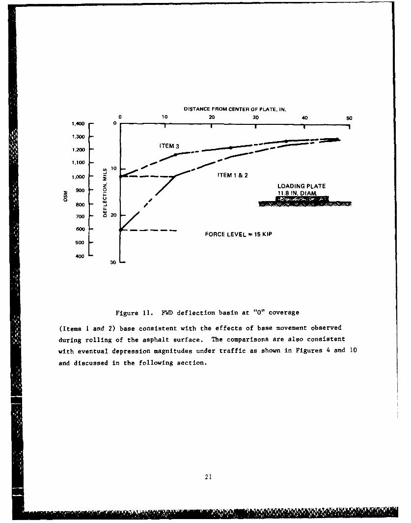
Figure 11. FWD deflection basin at "0" coverage
(Items I and 2) base consistent with the effects of base movement observed
during rolling of the asphalt surface. The comparisons are also consistent
with eventual depression magnitudes under traffic as shown in Figures 4 and 10
and discussed in the following section.
21

DISTANCE FROM CENTER OF PLATE, IN.
0 10 20 30 40 500
1ITEM 3
10
20
30 -i, LEGEND
uJ..... * 100 COVS / / --- i 300 CoV
....- A ~1,oocoV
40
50
q0
Figure 12. Deflected surface for FWD tests at coverage
levels of 100, 300, and 1,000
22

PART V: ANALYSIS OF TRAFFIC TEST DATA
36. The F-4 loading with the 27,000 lb at a 265-psi internal tire pres-
sure is considered to be a severe loading for an Army airfield pavement. For
the upper layers of the pavement such as the surface and base course, this
loading, because of the high tire pressure, is almost as severe as heavier
bomber aircraft. Because of the instability of the base material under only
3 in. of surfacing, as indicated by the movement occurring during construc-
tion, there was a concern that complete failure of the test section would
occur during the first pass of the load cart. Therefore, it was surprising
that the first of the traffic was uneventful. The movement under the load was
more noticeable for Items I and 2 than Item 3. As traffic progressed, it
became evident that more permanent deformation was occurring in Items I and 2
than was occurring in Item 3. Figure 13 presents a plot of the development
with traffic of permanent deformation for each of the test items. As can be
seen by 100 coverages, the deformation of Items 1 and 2 was approximately
twice that of Item 3. At 100 coverages the deformation of Item 1 was about
the same but slightly larger than the deformation of Item 2. After 100 cover-
ages, the deformation in Item I increased at a greater rate than the deforma-
tion in Item 2. At the end of traffic (1,000 coverages) the deformation of
Item 2 was 79 percent of the deformation of Item 1, and Item 3 was 44 percent
that of Item 1.
37. During the early part of traffic, it was noted that for Items 1 and
2, the deformed surface formed a "W." This W shape can be noted in the cross
sections given in Figures 5 and 6. The development of the W is an indica-
tion that some shear movement is taking place in the upper layers. Later in
traffic the deformation basin formed a deep bowel-type basin without upheaval
at the edge which would be an indication that the deformation is a result of
deep consolidation. Figure 14 presents a schematic representation of traffic
effects.
38. Fatigue cracking of the surface did not appear during traffic. At
about 10 coverages a single crack did appear along the west edge of the traf-
fic lane of Items I and 2. Later in traffic a crack appeared along the east
edge of the traffic lane. Both cracks grew in width as the deformation in-
creased. The fact that there was no fatigue cracking of the surface was an
indication that very little movement was occurring in the base. The
23

0 2
IL
0
-<- a- -
010 100 1000
TRAFFIC IN COVERAGES
Figure 13. Maximum surface deformation as a function of traffic
longitudinal cracks along the edge could be attributed to the deep deformation
creating the sharp bending of the surface at the edge of the traffic lane.
39. The FWD test conducted before and during traffic revealed interest-
ing information concerning the behavior of the test section. It is seen by
comparing the deflection basin before traffic to the deflection basin at
100 coverages that the maximum deflections from the FWD doubled with the start
of traffic. As traffic increased after 100 coverages, the deformations mea-
sured in the FWD tests (Figure 12) decreased for Items 1 and 2, but increased
for Item 3. One possible explanation for results obtained in the FWD test
would be in the performance of the PCC stabilized layer under the base. This
layer prior to traffic would have been intact. During traffic the cement-
stabilized layer cracked, the cracking being more rapid in Items 1 and 2 than
in Item 3. Prior to 100 coverages of traffic, the cracking for Items 1 and 2
was complete and then the section began to stiffen because of consolidation of
the lower layer. For Item 3 the stiffer base prevented the rapid breakup of
the cement-stabilized layer. The continued increase in the FWD deflection of
Item 3 could indicate a breakup of the asphalt-stabilized base.
40. Traffic was stopped at 1,000 coverages because the deformations had
become so great. The surface of all items at this time appeared to be in good
condition with no fatigue cracking.
24

SHEAR DISPLACEMENT SECTION AS
BENEATH TIRE CONSTRUCTED
PAVEMENT
BASE
SUBBASE
SUBGRADE
DISTRIBUTED TRAFFIC
ADJACENT PASSES EDGE PASSES
INDUCE COMPENSATING INDUCE CUMULATIVE
SHEAR REVERSALS SHEAR MOVEMENTS
THE PROCESS PRODUCES THE "W'" PATTERN
COVERAGES OF WHEEL-PASS REPETITIONS
DENSIFICATION OR DEEP SHEAR DISPLACEMENT
Figure 14. Schematic representation of traffic effects
25

41. After stopping traffic, a 3-in.-diam hole was drilled through the
AC surface to the base material. To check the permeability of the base, water
was poured into the hole from a 5-gal pail. The 5-gal pail could be emptied
in about I min without overflowing from the hole. The unstabilized base was
only slightly more permeable than the stabilized material.
42. Observation trenches were also cut through the surface and base to
the stabilized subbase. For all items the top of the subbase had the same
shape as the surface pavement indicating that most of the deformation did in-
deed occur deeper in the section. Also, the thickness of the base material
was still approximately 6 in. indicating little deformation in the base
material.
43. Since this was a pilot test study and not one justifying extensive
effort, the silty sand subgrade placed uniformly and compacted nominally with
the steel drum roller was considered to be a more than adequate platform for
the study, particularly considering the use of the cement-stabilized sandy
gravel subbase. The 27 CBR found for the subgrade easily justified this
expectation for pavement to support an F-4 aircraft loading, but this was the
"as-placed" CBR for the 8.3 percent moisture content and 121.1 psf density
determined for the subgrade. No substantial adjustment or curing of the mois-
ture was expected, as is known to apply to in-service pavements following con-
struction. Therefore, no effort was invested in subgrade soil strength
assessment. It now appears that because subgrade preparation was in early
August of 1982 and traffic applied to the test section in July of 1983, sub-
stantial soil moisture and strength adjustment may have occurred. This and
the unanticipated cracking of the cement stabilized subbase have apparently
resulted in a far less substantial structure than intended.
44. This combination of circumstances, which have led to the total
structure strength being challenged within the 1,000 coverages applied rather
than only base stability being a factor, may have a fortuitous aspect. The
after-traffic trenching indicated no thinning of the base layer and thus no
internal shearing within the base. However, the deformation of the total sec- V
tion was different for the three different base sections. Item 3 with bitumi-
nous stabilization had the least deformation. Item 2 with the geogrid rein-
forcement had somewhat less deformation than did Item 1 with no geogrid and no
stabilization. This implies that the different base types each had a differ-
ent capability for distributing stresses from top to bottom of the layer. Or,
26

in another sense, for equal behavior within the structure the stabilized base
thickness would be less than for the base with geogrid and either would be
thinner than the nonstabilized base.
45. This finding indicates that for development of open-graded bases
for drainage, in addition to permeability rates and stability to support con-
struction and perform as a base layer, it may be necessary to also learn to
treat varied load or stress distributing characteristics.
46. In the unstabilized base material it appeared that the top 3 in. of
the base had sustained more degradation than the bottom 3 in. To see if this
was in fact true, sieve analysis was conducted on samples from the top half
and from the bottom half of the base. The gradations obtained are shown in
Figure 15. From the gradation curve it would appear that there is no signifi-
cant difference in the two samples. Still, from observation it did appear
that the bottom half of the base was unchanged. This could indicate that an
additional 3 in. of cover over the open-graded base may be required.
47. The tensor fabric of Item 2 was uncovered and appeared to be in
good condition. There were no t ars or splits in the fabric, and the fabric
was still located at midheight of the base.
48. In spots the top of the asphalt stabilized open-graded base of
Item 3 was loose granular material. The maximum depth to which the debonding
of the aggregate extended was only about 2 in. Again, the indication is that
3 in. of AC cover is not sufficient to protect an open-graded base under this
loading. The debonding of the asphalt base could also help explain the
increase, with traffic, of the deflection in the FWD test.
27
42
j r

00
08
Z 'K04
o 0 rI 11 111 A II II I I I I1 1 111 1 1 A, L - S c
zE
04'
000
000
14
110
Ol0
(3~ '4
282
Z V

PART VI: CONCLUSIONS AND RECOMMENDATIONS
Conclusions
49. Based on the results of the pilot test section, the literature re-
view, and the examination of field installations, the following conclusions
are presented.
a. For the majority of the airfield pavements constructed withdense-graded bases, the base course is nearly impermeable.
b. Airfield pavements constructed with open-graded bases have beensuccessfully constructed and have performed well in field in-stallations. The open-graded bases can provide adequatepermeability.
c. Certain types of open-graded materials such as were used inthis pilot test section would give stability problems in sup-port of rolling thin cover layers.
d. Asphalt stabilization of an open-graded base will increase thestability of the base and will improve the pavement performance.
e. The stiffness of a pavement system with an open-graded base, asmeasured by the FWD, is comparable to the stiffness of pavementsystem having conventional bases.
f. The F-4 aircraft loading did not cause thinning of any of theopen-graded test items, which indicates there was no signifi-cant shear distortion within the bases tested.
. There is an implied need to develop an understanding of therelative load distributing capability of diverse types of open-graded bases in addition to their drainability and stability.
Recommendations
50. Based on the study, the following recommendations were formulated:
a. Additional research needs to be conducted on open-graded bases,particularly in regard to methods for increasing the stabilityof the base in the unconfined state. Such a study could beconducted in the laboratory using small-scale sections.Macadam-tvpe hase is one construction procedtire that neefir to
be investigated. Also, continued studies should be conductedwith the asphalt and cement-stabilized base.
b. A field study to determine the consequence of the use of imper-meable bases in airfield pavements should be conducted.
c. Early field demoristration project- for open-graded bases shouldbe planned. Such projects would use an open-graded base shownby the laboratory studies to be more stable than the unstabil-ized crushed stone used for the pilot test section.
29
p - - .,I, -

REFERENCES
Barker, W. R., and Gunkel, R. C. 1979(Aug). "Structural Evaluation of Open-Graded Bases for Highway Pavements," Miscellaneous Paper GL-79-18, US ArmyEngineer Waterways Experiment Station, Vicksburg, Miss.
Casagrande, A., and Shannon, W. L. 1952. "Base Course Drainage for AirportPavements," Transactions, Vol 117, paper No. 2516, American Society of CivilEngineers, New York.
Cedergren, H. R. 1974a. Drainage of Highway and Airfield Pavements, JohnWiley and Sons, New York.
Dempsey, B. J. 1976. "Climatic Effects on Airport Pavement Systems," Con-tract Report S-76-12, US Army Engineer Waterways Experiment Station,Vicksburg, Miss.
Federal Highway Administration. 1980a. "Highway Subdrainage Design," ReportNo. FHWA-75-80-224, Washington, DC.
____ . 1980b. "Evaluation of Test Methods and Use Criteria for Geo-
technical Fabrics in Highway Application," Report No. FHWA/RD-80-021,Washington DC.
Headquarters, Department of the Army. 1965. "Drainage and Erosion Control,Subsurface Drainage Facilities for Airfield Pavements," TM 5-820-2,Washington, DC.
Miller, S. P. 1979. "Filter Fabrics for Airport Drainage," ReportNo. FAA-RD-79-29, US Army Engineer Waterways Experiment Station, Vicksburg,Miss.
Monahan, A. 1981. "Porous Portland Cement Concrete; the State-of-the-Art,"Report No. FAA-RD-80-110, US Army Engineer Waterways Experiment Station,Vicksburg, Miss.
Nettles, E. H., and Calhoun, C. C. 1967(Jul). "Drainage Characteristics ofBase Course Materials Laboratory Investigation," Technical Report No. 3-786,US Army Engineer Waterways Experiment Station, Vicksburg, Miss.
30

Photo 1. Broken sample of cement-stabilized aggregate (Mix 1)
Photo 2. Broken sample of cement-stabilized aggregate (Mix 2)
U' N E 82
C~~OE rGRADED C t, '
8et ASS E

Photo 3. Broken sample of cement-stabilized aggregate (Mix 3)
BSE
A.1A
Photo 4. Laboratory sample of asphalt-stabilized aggregate(1.5% AC, Mix 3)

(2X AC4 ix4
Photo 6. Paverafory spln ofp-grabseiand surain
for test section

Photo 7. Roller for compacting test section
Photo 8. Vibratory roller used in compacting test section
-- o--
P. '%

Photo 9. Placing of geotextile fiber below base
Photo 10. Test section ready for placing of base
i- . lilii-i -i - . - ,,

Photo 11. Placing open-graded base
Photo 12. Close-up of unstabilized open-graded base
u -. 7

------ ------ -------------
Photo 13. Close-up of AC stabilized open-graded base
Photo 14. Placing of AC surfacing

)
Photo 15. Compaction of surface layer
PIPhoto 1.6. Completed test section

pJ~A21EL
A-AA im
Photo 18. Rutting of Item 2 after 100 coverages

Photo 19. Rutting of Item 3 after 100 coverages
--- -- --
4 33
Pht'09utngo.tm1ate 0 oeae

Pht 2 3 2utn of Itm2fe 3 c 4eae
Photo 22. Rutting of Item 3 after 300 coverages
Pht 22. vRutigo Ie ftr3-coeae

APPENDIX A: SUBSURFACE DRAINAGE FOR AIRFIELD PAVEMENTS
Introduction
1. Subsurface drainage of pavements is a topic of considerable interest
at the present time. Cedergren (1974)* and the Federal Highway Administra-
tion (FHWA) (1980a) have summarized most of the past work and present methods
of planning and designing subsurface pavement drainage. A National Coopera-
tive Highway Research Program (NCHRP) Synthesis on subsurface drainage is now
being prepared by Professor Ridgeway at the University of Connecticut. The
FHWA has sponsored much of the recent pavement drainage work, and a summary of
its current projects is listed on page A9.
2. The Corps of Engineers criteria were originally developed by
Casagrande and Shannon (1952) and are presented in TM 5-820-2 (Headquarters,
Department of the Army 1965). However, laboratory tests by Nettles and
Calhoun (1967) found that current Corps of Engineers base course material can-
not meet these drainage criteria when compacted to densities required in mili-
tary airfields. The Corps of Engineers as a minimum must revise base and
subbase material specifications to meet existing drainage requirements but
should also take advantage of the recent interest and research to review and
improve pavement drainage criteria.
Potential Benefits
3. Field studies by a large variety of investigators (summarized by
Dempsey 1976) found that in many cases soil layers in pavements become sat-
urated or nearly so even in arid regions. Since the actual final moisture
condition under a pavement cannot be predicted during design, saturated Cali-
fornia Bearing Ratio (CBR) and modulus of subgrade reaction (k) values cor-
rected for saturation (from consolidometer tests) are used for design. The
full potential strength of a soil cannot be used because of our inability to
control moisture. This results in dramatically lower design strengths for
* All references cited in the appendix can be found in the "References" at
the end of the main text. Other references applicable but not cited in thetext are listed at the end of this memorandum.
Al

many subgrade soils and to a lesser extent also for subbases and bases. The
end result is a thicker and more expensive pavement than would be necessary if
drainage could prevent loss of soil strength through moisture increases.
4. Pore pressure develops in pavement layers under the action of re-
peated loads. Although this phenomenon cannot be accounted for in current
pavement design methods, it has serious implications for the acceptable per-
formance of the pavement. The effective stress concept of soil mechanics
clearly shows that a rise in pore pressure directly reduces the strength of
all soils.
5. Professor Dempsey at the University of Illinois has recently devel-
oped a gage capable of measuring dynamic pore pressure. This instrument has
been used successfully in laboratory tests and at the Illinois test track.
Professor Dempsey's experiments (unpublished)* show that a transient load will
develop a measurable pulse of pore pressure in the saturated granular mate-
rials now used in pavement bases and subbases. Under repeated loading the
static or unloaded pore pressure in the layer increases steadily.
6. Pumping of rigid pavements cannot occur without water. If the water
can be kept out or removed from the layer below the concrete surface, pumping
cannot develop.
7. Water directly attacks the integrity of pavement surfacing mate-
rials. It can cause stripping and accelerated weathering of bituminous pave-
ments. In concrete pavements water combined with freezing temperatures can
lead to freezing and thawing damage to the concrete.
8. Freezing temperatures and water also lead to potential problems with
frost heave in the winter and extreme weakening of the pavement soil layers
during the spring thaw. Appropriate drainage facilities can be used to inter-
cept and remove water to prevent formation of ice lenses and the resulting
frost heave. Drainage also has the potential of removing water from a perched
water table in the pavement structure when the underlying soils are still fro-
zen during the spring thaw.
9. Either positive steps must be taken to control water in the pavement
structure or the destructive action of water must be designed for with the re-
sulting increase in pavement costs. Of the potential problems discussed in
* Subsequent literature review still has not revealed a presentation ofresearch experience with the dynamic pore pressure gage through 1986.
A2

this section, only the reduced design strength from saturated CBR and k
values is directly accounted for in pavement design. The other effects are
minimized by material specification (aggregate quality to resist freeze-thaw
damage in concrete, pumping resistant bases under concrete, etc.) or their
effect is ignored because of lack of information (pore pressure). Drainage
offers very definite potential advantages which should be studied; however, it
should not be considered a panacea for pavement problems.
Drainage Design and Construction
10. Drainage can be used to help solve or mitigate one or more of the
problems discussed above, but the drainage system must be designed to accom-
plish a specific purpose. A single drainage blanket alone, for example, will
not solve all the problems mentioned above. There are also different sources
of water in the pavement such as surface infiltration, water table, artesian
water, capillary water, temperature induced water movements, and several other
relatively minor sources. Every drainage system must be specifically designed
for each individual site to reflect the problem to be solved, sources of
water, local geometry, climate, and similar controlling factors. Cedergren
(1974) and the FHWA (1980a) present a variety of different potential design
schemes for varying problems and conditions.
11. The design of the drainage systems must ensure that water is re-
moved from the drainage layer, joint drain, etc., collected in a longitudinal
drain system, and then removed through outlets.*
12. The first requirement considered in design of a drainage layer is
the quantity of water inflow which must be handled. Several approximate
methods of estimating this are presented by the FHWA (1980a), but these are
recognized as only crude approximations. Better methods and more data in this
area are required.
13. The required thickness and permeability of a drainage layer are
generally developed from Darcy's law for laminar flow through porous media. ?A
This is recognized as only valid for fine grained soils. Flow in open-gradeddrainage material will be nonlaminar even at relatively low hydraulic gradi-
ents; nevertheless, Darcy's law continues to be used since other appropriate
* Future clogging or blockage of any part of the system must be considered.
A3

techniques have not been developed. Adjustments in the methods of running
laboratory permeability tests can help account for nonlaminar or turbulent
flow (FHWA 1980a).
14. Casagrande and Shannon (1952) compared the results of four full
scale drainage tests of 10 by 75 ft saturated bases consisting of pea gravel
and sandy gravel with theoretical calculations. These bases were 6 and 18 in.
thick and placed at slopes of approximately 1.5 percent. One item was
unsatisfactory due to excessive leakage, but two (pea gravel) out of three of
the remaining sections gave reasonable agreement with the theoretical calcula-
tions. This is the basis of the Corps subsurface drainage design method.
Permeabilities were in the range of 310 ft/day (0.11 cm/sec) to 59,500 ft/day
(21 cm/sec) with the sandy gravel averaging 765 ft/day (0.27 cm/sec) and the
pea gravel 41,100 ft/day (19.5 cm/sec).
15. Little has been published on the structural requirements of drain-
age layers. Cedergren (1974) provides several case histories of performance
and cross sections of pavements with drainage layers but does not elaborate on
how the thickness of the surfaces was developed. Barker and Gunkel (1979)
seem to be the first to develop tests for structural requirements for open-
graded drainage material. They concluded in part:
When provided with adequate overburden for confine-ment, both the stabilized and nonstabilized open-graded aggregates will perform as highway bases. Fornormal highway loading, the minimum overburden wouldbe approximately 6 in.
Open-graded material has been used successfully unstabilized and stabilized
with asphalt and cement. Experience in New Jersey with unstabilized and
bituminous stabilized open-graded drainage shows that both materials can be
constructed without undue difficulty. The bituminous stabilized material
offers a somewhat more stable working surface. Major problems in construction
were segregation and contamination of the aggregate rather than placement or
compaction of the drainage layer. Both types of material could support normal
wheeled and tracked construction equipment. An asphalt laydown machine with
small wheels rather than the more common tracks did bog down in the unstabi-
lized drainage layer but also did the same in a nearby base course material.
The asphalt stabilized material had to cool to lower temperatures (around
2000 F) than normal asphaltic concrete (AC) to prevent rutting and shoving
A4

under the roller. Porous concrete mixes have also been used for drainage and
are summarized by Monahan (1981).
16. Contamination of the drainage layer must be prevented at all times.
During construction stockpiles of drainage material must not become contami-
nated from blowing or washing fine material. Once the drainage layer is in
place, wind blown and washed contaminants remain a potential problem. Traffic
on the drainage layer must be kept to an absolute minimum to prevent fine
material from entering and clogging the layer. Once in place, the drainage
layer must be surfaced as soon as possible.
17. Once the drainage layer is functioning, water passing through the
layer can carry material from surrounding area and clog the layer. This is
aggravated by dynamic traffic loads. Positive filter protection must be pro-
vided to ensure that the drainage layer does not become clogged. Requirements
for filter layers are provided in TM 5-820-2 (Headquarters, Department of the
Army 1965). Filter fabrics have given mixed results. Performance history and
criteria for their use are provided by the FHWA (1980b) and Miller (1979).
New Jersey has gone to the extent of requiring a stabilized layer under the
drainage layer.
18. Maintenance of outlets is a major requirement for a successful
drainage system. Without it, outlets will clog and ruin the effectiveness of
the system. The practice of "daylighting" a drainage layer appears question-
able since blockage by fill, washed material, and vegetation seems likely.*
Drainage Application to Airfields
19. Most subsurface drainage has been oriented toward highway applica-
tions rather than airfields. Casagrande and Shannon (1952) described drainage
problems at five airfields; four of these had subsurface drains, and one had a
"daylighted" base. Cedergren (1974) describes a portion of a military heavy-
duty aireield taxiway which has a 6-in.-thick AC surface over a 6-in. open-
graded drainage layer. The field is not identified. Miller (1979) described
the installation of a drainage system at Jacksonville airport. Other tI* Early experience has shown that lateral drains of "French-drain" construc-
tion using only relatively low permeability (less than 5 percent of minus200 size) material leads to clogging and entrapment of water in the base.
A5

open-graded drainage installations are at Kansas City and Portland airports.
Only Casagrande and Shannon (1952) reported quantitative performance data.
20. Extending the highway experience to airfields raises several prob-
lems. Runways, taxiways, and aprons are much larger and will have longer
drainage paths than highways. Since Darcy's law is of doubtful validity in
analyzing flow in highly permeable open-graded drainage material, the calcu-
lation of design permeabilities, thicknesses, flow rates, etc. cannot be done
with confidence. The problem is compounded for these long drainage paths
where errors in the basic assumption of laminar flow may have a significant
impact on design calculation.
21. Table Al shows that if the assumptions of the FHWA (1980a) design
recommendations are accepted for an approximation, an airfield pavement 150 ft
wide could be kept drained for several design storms with a 6-in.-thick drain-
age layer with a permeability of 3,000 to 8,000 ft/day. If the base becomes
saturated, Table A2 shows the length of time required to achieve several de-
grees of drainage for different permeabilities. The permeability of
0.28 ft/day (10- 4 cm/sec) is equivalent to the heavily compacted base course
aggregates tested by Nettles and Calhoun (1967). Tables Al and A2 suggest,
within the limitation of the calculation method, that permeabilities on the
order of 1,000 to 10,000 ft/day would be appropriate for open-graded drainage
layers for airfields. Figure Al from the FHWA Manual (1980a) suggests that
this limits consideration to uniform coarse sands and gravels. The Casagrande
and Shannon test (1952) with a sandy gravel having an average permeability of
765 ft/day did not give results that agreed with the theoretical calculations
based on laminar flow assumptions. The other Casagrande and Shannon test with
sandy gravel was considered a suspect because of leakage in the test, but it
also did not agree with theoretical calculations. These tests are of particu-
lar concern because there are only known tests which used drainage paths and
slopes appropriate for an airfield.
22. Structural requirements are a greater problem for airfields than
for highways due to the large aircraft loads. However, as previously dis-
cussed, there is little or no information available in this area. This is a
question requiring further investigation and testing.
A6
ra Ir a*" ;V I~a p

Table Al
Required Permeability of a 6-inch Drainage
Layer to Prevent Saturation
1 Hour/i Year Infiltration Required k
Frequency of Storm* Coefficient* q** ft/day
2.0 0.50 1.00 5,900
0.67 1.34 7,900
1.5 0.50 0.80 4,700
0.67 1.00 5,900
1.0 0.50 0.50 2,900
0.67 0.67 3,900
* Cedergren's method of estimating surface infiltration. Infiltration Coef-
ficient of 0.33 to 0.50 for bituminous pavements, 0.50 to 0.67 for concretepavements.
** q is design infiltration rate.
Drainage path length, 75 ftGrade (maximum allowable transverse), 1.5%Drainage layer maximum depth of flow, 6 in.
Figure 46 of FHWA Highway Subdrainage Design Manual is used to calculate k.
Table A2
Time Required for Drainage of a 6-inch-Thick Layer
Time Required to Reach u
Degree of k = 0.28 k = 100 k = 1,000 k = 10,000Drainage (u) t/m* ft/day ft/day ft/day ft/day
30% 0.066 53 days 14 hours 2.3 hours 25 minutes
50% 0.145 117 days 1.3 days 5.1 hours 54 minutes
90% 0.540 434 days 4.8 days 19.0 hours 3.4 hours
nL2
f - time and m = -
.--_ KdHd
where: n' - yield capacity; L - Length; Kd = coefficient of permeabilityH - thickness
Figure 4 7dof FHWA Highway Subdrainage Design Manual is used for calculatingtimes.
Thickness of layer, 6 in.Length of drainage path, 75 ftTransverse slope, 1.5%
A7
.\ -

Conclusions and Recommendations
23. The following conclusions were determined.
a. There is sufficient potential benefit in airfield pavementdrainage to warrant new Corps of Engineers research andtesting.
b. Existing Corps of Engineers subsurface drainage criteria(Headquarters, Department of the Army 1965) does not appearadequate in view of the results of Nettles and Calhoun (1967)tests and recent FHWA (1980a) work.
c. There are a number of major questions about pavement drainagewhich can only be answered by further research and testing.
24. The following recommendations were made to conclude FY 81 study,
a. Visit Professor Ridgeway to review his progress on the NCHRPSynthesis.
b. Visit Jacksonville, Kansas City, and Portland airports to ob-tain as much detailed design, construction, and performancedata as possible.
c. Visit Michigan and California Department of Transportationto obtain available specifications, design, and performancedata from their highway drainage projects.
25. Recommendations for future work were made as follows:
a. Insufficient data are available on water inflow into pavements.Better methods of estimating inflow rates are necessary todevelop design capacities for drainage layers.
b. Major questions remain unanswered concerning the validity ofour current methods of calculating flow in drainage layers withthe assumption of laminar flow. This can only be answered withfull scale experiments similar to those reported by Casagrandeand Shannon (1952). These tests should include a conventionalcrushed stone base as a control and then other materials withpermeabilities in the range contemplated for drainage layers(1,000 ft/day to 10,000 ft/day).
c. There is not adequate experimental data available to allow anevaluation of the structural capacity of open-graded drainagelayers for airfields. Basic performance data from laborptoryand trafficking tests must be developed before analyticalmethods of selecting cover requirements can be developed.
d. Open-graded drainage layers are in place at several airports.These should be instrumented and monitored by WES to obtainperformance data if possible. Instrumentation should includeareas without the drainage layers for comparison. Desirabledata would include quantity of flow, in-place permeability,dynamic and static pore pressure, moisture contents, andnondestructive test structural evaluations.
A8
C,~.~ < ~

Current Research on Subdrainage and Related Topics
FHWA Administrative Contracts
1. "Improving Subdrainage and Shoulders of Existing Pavements"
Principal lnvestigators: Drs. Michael Darter and Barry Dempsey,University of Illinois
Objectives: Establish criteria for the early identification of existingpavements in need of improved subdrainage and shoulders. Develop a methodfor determining optimum time to effect remedial measures. Establishguidelines for making improvements in subdrainage and shoulders. Pavementdistress identification manual and procedures for identifying "MoistureAccelerated Distress" should be included in final report as well asshoulder design guides.
Five reports to be published in 1981:
a. "Structural Analysis and Design of PCC Shoulders"
b. "Improving Subdrainage and Shoulder of Existing Pavements - State ofthe Art"
c. "A Pavement Moisture Accelerated Distress Identification System UsersManual, Volume I"
d. "A Pavement Moisture Accelerated Distress Identification System UsersManual, Volume II"
e. "Improving Subdrainage and Shoulders of Existing Pavements, FinalReport"
2. "Test Methods and Use Criteria for Filter Fabrics"
Principal Investigators: Drs. J. R. Bell and R. G. Hicks, Oregon StateUniversity
Objectives: Identify criteria for the engineering use of filter fabrics,particularly in subdrainage, erosion control, and soil reinforcementapplications. Modify existing test methods and develop new test methodswhere needed to evaluate the engineering properties of filter fabrics.
FinalRepor - sometime in 1981
3. "Use of Filter Fabric as a Subgrade Retainer"
Principal Investigator: Mr. Larry Smith, Florida Department ofTransportation
Objectives: Compare construction techniques and performance of threetypes of fabrics separating embankment material from underlying softorganic subsoil.
A9
Kkf. *-

Completion Date - 1981 (Contract managed by FHWA Implementation Division -
Mr. Chang).
4. "Engineering Fabrics Training Course"
Principal Investigators: Haliburton and McGuffey
Objectives: Develop course material and conduct workshops.
Completion Date: 1981
NCHRP Contracts
1. Project 4-11 "Buried Plastic Pipe Drainage of Transportation Facilities"
Contractor: Simpson, Gumpertz, and Heger, Cambridge, Massachusetts
Principal Investigators: Richard Chambers, Frank J. Heger
Objective: Develop and evaluate the design, installation, and performancecriteria for the use of buried plastic pipe in transportation facilities.
Final Report Published December 1980.
2. Synthesis Topic 11-07 "Pavement Drainage Systems" in NCHRP Project 20-5
Principal Investigator: Dr. Hallas Ridgeway
Objective: Establish the state of the art in design theory, and actualdesign and construction practices.
Completion Date: 1981
HPR Studies
1. Alabama - "Design Parameters for Longitudinal Filter Cloth LinedSubsurface Pavement Drainage Systems"
Principal Investigator: John Ball
Objectives: Measure filter performance under controlled conditions,evaluate in field and propose specifications and test methods.
Completion date: Draft Final Report received in December 1980
2. Alaska - "Applications of Engineering Fabrics in Alaska"
Principal Investigator: Johnson
Objective: Review performance of fabric installations and recommendguidelines for future use.
Completion date: Unknown
AIO
- ~ ~ ~ ~ ~ - 1~ -;v %~K& '"'

3. Alaska - "Roads on Muskeg"
Principal Investigators: Johnson and Moses
Objective: Reevaluate treatments to minimize settlement and distortion ofroadways over peat deposits.
Completion Date: September 1981
4. California - "Specification Expansion for Fabric Filters"
Principal Investigator: Forsythe
Objective: Establish standards of filtering capacity and permeabilitywith appropriate test methods for nonwoven fabrics in civil engineeringapplications.
Completion Date: June 1981
5. California - "The Effectiveness of Horizontal Drains"
Principal Investigator: Duane Smith
Objective: Develop effective cleaning system and maintenance andrehabilitation program.
Completion Date: Draft report being revised.
6. Florida - "Permeability Characteristics of Base, Subbase, and StabilizedSubgrade Materials:
Principal Investigator: K. H. Ho (Florida Department of Transportation)
Objective: Measure permeability of typical construction materials.
Completion Date: Unknown
7. Illinois - "Soil Water Properties of Subgrade Soils"
Principal Investigators: Janssen and Dempsey
Objectives: Determine the soil-water characteristics and saturatedhydraulic conductivity of major soil types in Illinois.
Completion Date: Final report published in 1980.
8. Kentucky - "Subsurface Drainage System for Highway Pavements"
Principal Investigators: Newberry and Havens
Objectives: Design, construct, and observe the performance of a pavementhaving a positive subsurface drainage system.
Completion Date: 1981
All
m\

9. Michigan - "Drainage and Foundation Studies for an Experimental Short
Slab Pavement"
Principal Investigators: M. Chiunti, T. M. Green, and E. C. Novak, Jr.
Objective: Evaluate the comparative performance of jointed concretepavement placed on conventional base, a porous bituminous drainageblanket and on a bituminous base.
Completion Date: 1981? (Field test sections completed and underobservation)
10. New Jersey - "Improved Drainage and Frost Action Criteria for New JerseyPavement Design"
Principal Investigator: George Koslov
Objectives: Develop new pavement subdrainage criteria consistent withrequired strength and frost resistance.
Completion Date: 1981?
11. Ohio - "Development and Implementation of Pavement Drainage DesignGuidelines in Ohio"
Principal Investigators: Elmitiny and Majidzadeh
Objectives: Develop designs and construction specifications andguidelines for improved pavement subdrainage in new pavements.
Completion Date: 1981
A12
i4 ~ . - -p

References
Subsurface Drainage1981
Barber, E. S., and Sawyer, D. L. 1952 (Feb). "Highway Subdrainage," PublicRoads, Volume 26, No. 12.
Cedergren, H. R. 1974. "Drainage of Highway and Airfield Pavements," John
Wiley and Sons.
. 1968. "Seepage, Drainage, and Flow Nets," John Wiley and Sons.
Cedergren, H. R., Arman, J. A., and O'Brien, K. H. 1973 (Feb). "Guidelinesfor the Design of Subsurface Drainage Systems for Highway Pavement StructuralSections," Final Report, Report FHWA-RD-73-14, (PB231173/AS).
Cedergren, H. R., O'Brien, K. H., and Arman, J. A. 1972 (Jun). "Guidelinesfor the Design of Subsurface Drainage Systems for Highway Structural Sec-tions," Summary Report, FHWA-RD-72-30.
"Dewatering: Literature Review" Information Series, Group Z, Number 9,September 1977, Transportation Research Board.
Federal Highway Administration. 1980a (Aug). "Highway Subdrainage Design,"Report No. FHWA. TS-80-224, Washington, DC.
"Pavement Rehabilitation," Proceedings of a Workshop, Transportation ResearchBoard, July 1974.
"Proceedings, International Conference on Concrete Pavement Design," PurdueUniversity, February 1977.
"Proceedings, Symposium on Road Drainage," Organization for EconomicCooperation and Development, 1978.
Slaughter, G. M. 1973. "Evaluation of Design Methods of Subsurface DrainageFacilities for Highways," Georgia Institute of Technology, Georgia DOTResearch Project No. 6901.
A13
V. V VV V V
........ '

FINE SANDMEDIUM COARSE GAEFIN SNDSAND SAND100
- 90
- 80
MA TERIA L- 70
30
- 0200 0 50 30 2 16 108 1" " 3
US SANDAD SEVE IZE
Figue A. Tpicl grdatonsandpermabiitis o
-~~ 30**' ,

APPENDIX B: MEMORANDUM FOR RECORD
WESGP 23 June 1981
MEMORANDUM FOR RECORD
SUBJECT: Subsurface Drainage, Jacksonville, FL
1. Person contacted:
Mr. Charles HardrickDirector of Operations
Jacksonville Port AuthorityPO Box 18097International Airport
Jacksonville, FL 32229Telephone No. 904-757-2265
2. Additional referenced obtained:
a. Project drawingsb. Project specifications
c. "Comprehensive Study and Engineering Report for the Reconstruction of
the Terminal Apron and Taxiways at the Jacksonville International Airport"
3. Jacksonville Airport has a problem with a perched water table. Severalareas of the aprons show extensive staining from water seepage. Subgrade in
the airport area is variously a SC, SM, or SP with a blue-gray "Gumbo" clay
layer at shallow depths.
4. A keel section (50 by 7,000 ft) of runway was constructed in 1979. This
section consisted of a filter cloth on the subgrade, 6-in. open-gradeddrainage layer, 6-in. econocrete layer, and a 16-in. PCC pavement. Trenchdrains with pipes collect the overflow from the drainage layer and dischargeit into open drainage ditches. Two apron and parking areas have since beenreconstructed with drainage layers, and a fobrth should begin construction bythe end of July.
5. Performance of drainage areas is considered satisfactory by the PortAuthority. This is based on visual appearance of water outflow of pipes and
lack of cracking or staining in new pavements with drainage layers.
6. Drainage layer aggregate used in one project section currently nearing
completion is a dusty limerock devoid of sand or fine aggregate sizedparticles.
BI

WESGP 23 June 1981SUBJECT: Subsurface Drainage, Jacksonville, FL
7. Inspectors report no particular problems with construction. The drainagelayer is compacted with two passes of a vibratory roller (RayGo 400A on thisproject). All concrete is formed with saw cut joints in econocrete matchingsurface joints.
RAYMOND S. ROLLINGSEngineerPavement Systems DivisionGeotechnical Laboratory
B2
!V "h

WESGP 17 August 1981
MEMORANDUM FOR MR. A. H. JOSEPH, CHIEF, PAVEMENT SYSTEMS DIVISION*
SUBJECT: Report of Trip to Study Pavement Subdralnage Design, 6-24 July 1981
1. INTRODUCTION. This trip took me to three California DOT District Officesand a like number of California highway projects under construction; two largecivilian airports, one in Portland, OR and the other in Kansas City, MO; theMain Office of the Michigan DOT and their Research and Materials Laboratory aswell as two existing highways. One of the latter included 6 miles of experi-mental pavement.
2. THREE DISTRICT OFFICES OF CALIFORNIA DOT.
a. Monday through Wednesday, 6-8 July 1981; District No. 7 located inLos Angeles. Individuals contacted at the District Office: Fred Correa,Branch Chief of Engineering Services; William Lum, Hydraulics Engineer; JimNakamura, Materials Engineer; Patricia Perovich, Project Development Engineer;Dan Butler, Senior Engineer, Project Development Branch; Seige Watanabe, Mate-rials Project Engineer. I obtained plans and specifications of their subpave-ment drainage designs and visited two highway construction projects in thedistrict. Both projects included longitudinal drainage consisting of an8-in.-diam perforateL steel pipe (PSP) encased in cement-treated permeablematerial (CTPM), running longitudinally beneath the shoulders. The roadwaypavement for both projects consists of a variable thickness PCC pavement slab.The remainder of the pavement structures differed. The 1-118 freewaycalls for a 0.40 ft lean concrete base directly under the pavement overlayinga 0.40 ft aggregate base. A section of 300 ft includes a permeable drainageblanket under the PCC slab. This area is reputed to have a wet subgrade. The1-210 freeway designers chose to use a two-layer drainage system because ofthe high ground-water level. The section as designed consisted of 0.65 ft ofCTPM over 0.25 ft of a Class 3 Asphalt Base. However, during construction the0.65 ft CTPM was reduced in thickness to 0.45 ft. Over the CTPM, directlybeneath the concrete pavement, a 0.20 ft layer of AC was placed. The CTPM asbuilt is primarily against groundwater and not for protection against precipi-tation. On both projects it was assumed that runoff would work its waythrough the joints and cracks of the PCC pavement and that the lean concretebase in the case of 1-118 and the AC on the 210 freeway will act as aquifers
* Appendix information describing supporting documents has been deleted fromthis memonrandum.
B3
L3

WESGP 17 August 1981SUBJECT: Report of Trip to Study Pavement Subdrainage Design, 6-24 July 1981
and lead the precipitation to the longitudinal drainage system outside thepavement edges.
b. Thursday, 9 July 1981, District No. 7 located in San Bernardino. Imet with Mr. Tom Griffin, their Hydraulics Engineer, who offered nothing newthat I had not already obtained from the Los Angeles District. However, I didvisit a section of 1-15 near Lake Elsinore. That highway is being retrofittedwith a longitudinal drainage system along both shoulders. The design againconsists of a filter fabric-lined trench with an 8-in. PSP encased in CTPM.
c. Friday, 10 July 1981, District No. 11 located in Sacramento. I met
with Mr. Dale R. Schmodt, their District Hydraulics Engineer. Contrary to in-formation that I received from the CA DOT Head Office in Sacramento, this dis-
trict has not constructed nor is it in the process of building a section ofhighway pavement with the type of drainage design. However, the engineers areworking on plans for highway designs that will incorporate the use of subpave-ment drainage systems. This they shared with me. I also spoke with two engi-neers from the CA DOT Transportation Laboratory in Sacramento. I wasinterested in the technical parameters for their treated permeable material.Mr. Raymond A. Forsythe, Chief of the Soil Mechanics and Pavement Branch, pro-
vided me with some basic Information on ATPM as well as a copy of their labor-atory report. In essence the ATPM consists of an open-graded aggregatebetween 3/4 in. and No. 4 aggregate bound with 2 percent AC which was foundjust enough to hold the particles together during construction. The placement
temperature is between 250 and 3000 F but may require cooling before it can berolled. In the conclusion of this memorandum I will attempt to summarize someof the conclusions that I have seen in the field or read about in the litera-
ture. For the CTPM, I consulted with Mr. William Neal also from the CA DOTLaboratory. An interesting feature that I found in California's rigid pave-ment designs is that they do not provide for any dowels at their tranversejoints, tie bars at longitudinal joints, nor is any effort made to seal thejoints.
3. PORTLAND, OR: MONDAY-WEDNESDAY, 13-15 JULY, 1981. I visited the Officeof the Port of Portland on Monday. My point of contact was Mr. Jack Stiller,Project Manager for the Portland International Airport. Mr. Dick Lynch, a
design engineer, took me out to see the airport paving. Two pavements were
examined:
a. In 1974 a 2,200-ft extension on Runway LOR and parallel taxiway wereconstructed. The pavement was designed by Nai Yang based upon criteria thathe developed while with the New York Port Authority. The structure of thepavements is somewhat unusual consisting of an AC surface course over a deeplime-cement-pozzolan-filler stabilized base. The specifications are included
in Appendix B-02.650-1 and two drawings, Nos. P/A 74-3 1/58 and 18/58.
B4

WESGP 17 August 1981SUBJECT: Report of Trip to Study Pavement Subdrainage Design, 6-24 July 1981
b. In 1979 2,500 ft of the north parallel taxiway were reconstructed, in-corporating a 4-in. open-graded drainage blanket and an 8-in. perforated cor-rugated metal pipe. Mr. Lynch, the designer of the pavement, offered niscomments on the "Questionnaire for Pavement Drainage Study."
c. While no studies have been conducted on any of the airport pavements,the Port of Portland indicated that they would be interested in participatingin such a study with WES. The 1979 pavement was designed according to Ceder-gren's concepts and, therefore, may prove a good candidate for such aninvestigation.
4. KANSAS CITY, MO: WEDNESDAY AND THURSDAY, 15-16 JULY, 1981. I met withMr. Bob Harrar of Burns and McDonnel, Consulting Engineers, who were involvedin the design of the Kansas City International Airport (KCI) and Mr. FredBerge, an engineer with the KCI. The section of pavement that was of primaryinterest was Taxiway C which is roughly 750 ft long by 75 ft wide. The pave-ment structure consists of 14 in. PCC pavement (reinforced), 6 in. AC base,and 6 in. untreated permeable material connected to longitudinal 6 in. PSPdrains along the shoulders. The plans and specifications for this construc-tion are attached along with an evaluation questionnaire that was completed byMr. Harrar.
a. The problem with evaluating the performance of the pavement design isthat no systematic investigation has been undertaken to gather any data. Thisholds true for the drainage blanket, the subdrainage system, and all otherelements of the pavement structure. Occasionally and on an informal basis thecondition of the pavements is inspected. The only criteria seem to be whetherthere Is a visible pavement deterioration. The same holds true for the struc-tural elements and for drainage features. The answers to the questionnairethat I left with Mr. Harrar further attest to this conclusion.
b. The airport pavements have been constructed over a period in excess ofthirty years with numerous design techniques represented. The same holds truein some cases even for a single facility. Of all the locations that I vis-ited, the owner which is the City of Kansas City Aviation Department seemedthe most amenable to permitting WES to conduct studies of its pavement. Ibelieve that Mr. C. Frederick Berge, the Airport Engineer, would prove mostcooperative to such an undertaking.
c. My own visual observations of the pavements indicated that they seemedto be in good condition. From the scanty information that is available it ap-pears evident that where open-graded drainage layers have been used, placingthem beneath an impervious asphalt base does not permit them to drain waterthat has intruded into the pavement. Instead the precipitation flows beneaththe PCC pavement slab and the asphalt base. The drainage blanket under theasphalt course may be carrying capillary moisture below the pavementstructure.
B5

WESGP 17 August 1981SUBJECT: Report of Trip to Study Pavement Subdrainag8 Design, 6-24 July 1981
5. LANSING, MI: FRIDAY-FRIDAY, 17-24 JULY, 1981. The agency that I visitedhere was the Michigan DOT. The persons with whom I had contact and spent ap-proximately a week of discussion and field investigation are as follows: KentAllemeier, Chief of Testing and Research; Don Mallot, Chief of Soils and Mate-rials; Thomas A. Coleman, Supervising Engineer for Soils; Fred Copple, Head ofResearch Services Unit; Carl Mainfort, Head of Soils Research; Edward Novak,Supervisor for the Flexible Pavements Rheology Group; Shiou-San Kuo, PhysicalResearch Engineer; Leroy T. Dehler, Director of the Research Laboratory; andThomas Green and Manual Chiunti, Engineer Technicians.
a. The significant results of the visit to the MI DOT headquarters werethe technical reports and other pertinent material obtained and the investiga-tion of the experimental road section which is a 3 mile stretch of dual road-way on US 10, northwest of Clare, MI. I expect to receive a set of slidesfrom the MI DOT on the construction of this test section. Unfortunately, theroll of film that I took of the existing condition of the 12 test strips wasalmost all overexposed. However, I made notes "n each of the photographstaken. The sections and typical cross-sections for each of the four types ofpavement are listed below. What is not shown is the retrofitted drainagerecently installed along the right shoulder at the Type D pavement strips. Atstrip No. I the longitudinal drain was continuous, while at Nos. 3 and 9 itwas only installed at the transverse joints. The details of this drainagei stallation are also listed. Essentially it is merely a pea gravel-filledtreeich.
Section PavementNo. Type Comments
1 D Faulting at most transverse joints between 1/4 in.to 1 in. Cores taken at joints indicated a loss offines under the slab in direction of traffic.
2 A Transverse cracking in the middle or third pointsof a number of slabs. No faulting of transversejoints evident.
3 D Same as for Section No. 1.
4 B Pavement appears in good condition.
5 C Pavement appears in good condition. Cores weretaken adjacent to the transverse joints to evaluatethe condition of dowels. The plastic-coated oneswere in the best condition followed by those coatedwith epoxy with the noncoated dowel bars mostaffected by corrosion.
B6

WESGP 17 August 1981SUBJECT: Report of Trip to Study Pavement Subdrainage Design, 6-24 July 1981
Section PavementNo. Type Comments
6 A Pavement appears in good condition. Transversecracks in Section No. 2 are not evident.
7 C Pavement appears in good condition.
8 A Some slabs exhibit severe intermediate cracking withpractically all slabs showing lesser degrees of it.
9 D Considerable D-type cracking evident and much waterstanding along the transverse joints which indi-cates that pumping has taken place.
10 B Pavement appears in good condition.
11 C Pavement appears in good condition.
12 B Pavement appears in good condition.
b. Another slight modification was recently made to the pavement of thisexperimental strip. A joint was cleaned out between the PCC pavement and theAC shoulder. This space was filled with a sealant called "Sof-Seal Joint andCrack Sealing Compound." Based upon the feel of the material in the field,its memory that I was able to observe by manipulating it, the perfect condi-tion that it appeared to be in, I consider it one of the most remarkable sub-stances of its kind that I have ever come across. It is produced by W. R.Meadows, Inc., PO Box 543, Elgin, IL 60120. I have a long history of fail-ures in joint sealants some of which are recorded in an article that I wrotefor "Public Works" entitled "Search for Ideal Pavement Joint Sealants."
c. This experimental section of US 10 is about five years old. Two ofthe four pavement types, A and D, show considerable distress. The two pave-ment types that appeared in all three sections in good condition, withoutvisible stress, were B and C- Note the similarity of design between C and Dexcept that Type C has dowel supports at the transverse joints. My overallimpression is that Type B was the better design and is perhaps also the moreeconomical one to construct.
6. DISCUSSION. It is difficult, if not impossible, to separate the subdrain-age design from the overall consideration of the pavement structure. The gen-eral harmful influence of water upon a pavement structure is considered to bea major contributor to unsatisfactory performance and even failure. This situ-
ation manifests itself in rutting, cracking, faulting, increasing roughness,and a relatively rapid decrease in the level of the pavements serviceability.Trapped water in the pavement structure (surface, base, and subbase courses)and in the subgrade can result in pavement distress and ultmately to an unac-ceptable level of serviceability. Excess moisture from either precipitation
B7

WESGP 17 August 1981SUBJECT: Report of Trip to Study Pavement Subdrainage Design, 6-24 July 1981
or groundwater adversely affects the ability of a pavement to sustain dynamicloads imposed by traffic. In flexible pavements the damage is caused by thetemporary development of high pore water pressures in the aggregate courses ofthe pavement structure and in the subgrade under the influence of dynamicwheel loads. In the case of rigid pavements the mechanism is somewhat differ-
ent. The thermal regime results in a warping of the concrete slabs. A spaceis created between the underside of the concrete slab and its subbase or sub-grade which Increases in size under the strains due to the traffic loads.When free water is trapped beneath a slab joint, an approaching wheel loadcauses the leading joint edge (in the direction of traffic) to deflect down-ward as the trailing pavement slab edge rebounds upward. The result is a jet
of water and suspended fine soil particles opposite to the direction of traf-fic which causes a faulting at the 'oint with the trailing edge moving upwardrelative to the forward edge. If the transverse joints are not tightly sealeda pumping action can be observed. This phenomenon can also be seen along the
outside edges of a pavement. While pumping and blowing are generally associ-ated with rigid pavements, a somewhat similar process can also take place inflexible pavements. There are a number of ways to deal with this problem, butthe most effective is to prevent free water from accumulating under pavement.
I Other harmful effects of free water upon pavements are due to freezing and
thawing cycles and as a contributor to D-cracking of rigid pavements.
a. The faulting phenomenon was clearly evident in pavement Type D of theexperimental section of US 10 in Michigan. Except for Type B which had anATPM subbase, Types A and C which did not exhibit faulting have dowelassemblies at the transverse joints. Interesting also that the onlyD-cracking observed was in the Type D pavement. From what we know ofD-cracking, the presence of free water in pavement joints is a contributing
factor.
b. The method for determining the drainability of the various pavement
courses was first pioneered by Dr. Arthur Casagrande in 1951. At that time,
Professor Casagrande recommended that 10 days be allowed for drainage of thevarious untreated aggregate layers in a pavement structure. Casagrande'smethod of subbase drainage design utilized filter layers of well-graded mate-rials possessing relatively low permeability, k , in the order of 100 ft/day
or less and an effective porosity ne in the order of 0.1 or less.
c. The concept of drainage layers or blankets is predicted upon open-graded aggregate materials with a permeability, k , of at least 10,000 ft/dayand an effective porosity in the crder of 0.2. The design drainage time ofthis layer is usually kept to a maximum of I hour. However, the design anal-yses tools developed by Dr. Casagrande 30 years ago are still applicable.Prior to the introduction of open-graded drainage layers, subsurface drainage
was generally used to remove ground water and water originating from artesiansources but not for the rapid disposal of surface water that infiltrates intothe pavements structural section. The objective of these open-graded drainagelayers is to rapidly reduce the period of exposure of the entire pavement
B8

WESGP 17 August 1981SUBJECT: Report of Trip to Study Pavement Subdrainage Design, 6-24 July 1981
structure to excess water. Even when sealed pavement surfaces conduct precip-itation like sieves.
d. These open-graded drainage layers are an integral part of the pavementstructure and should be placed immediately below the pavement surface. Thebasic components of such a system include:
(1) The open-graded highly permeable drainage layer. The dischargecapability is derived from Darcy's equation for laminar flow Q/i = kA where
Q = the flow in cu ft/day, i = hydraulic gradient in ft/ft, k = permeability
in ft/day, A = an area in sq ft. Therefore, the capacity of a drainage layeris dependent upon permeability, thickness of the layer, and the hydraulicgradient within the layer. The latter is determined by the pavement cross-slope and the longitudinal grade.
(2) Protection of the open-graded filter layer against clogging.Protection must be provided during construction and for the life of the pave-ment. Protection can be developed by the use of filter layers, filter fabric,or by constructing the filter blanket on a fairly impervious foundation suchas an asphalt-treated base or a low-strength concrete base. All methods toprotect the filter layer envision it being constructed in a "sandwich" effect.
(3) Collector trench and perforated pipe. These are generally drainsplaced outside of and parallel to the pavement edges. The perforated pipeshould be between 3 and 8 in. in diameter, enveloped with a minimum of 6 in.of carefully placed and properly graded filter aggregate which may be asphaltor portland cement treated or untreated. It is often necessary to line thetrench with a filter fabric to protect the open-graded aggregate in the trenchfrom infiltration of fines.
'A
(4) Pipe outlets. Must be installed at locations and intervals dic-tated by hydraulic design considerations to ensure a completely free-drainingsystem for the life of the pavement.
(5) Markers. Should be installed at each collector pipe outlet toassure visibility for maintenance purposes.
e. At all four locations visited, California, Portland, OR, Kansas City,MO, and Lansing, MI, limited sections of pavement have been constructedincorporating elements of subdrainage blankets. At none of these locationswere any rigorous efforts made to develop analytical data on the performanceof these sections. The opinion of the engineers toward this approach to pave-ment design is favorable. Attached are the results of a questionnaire that Iprepared before starting on this trip. The most significant project visitedwas an experimental portion of freeway located on US 10 northwest of Clare, MIWhile at Lansing, MI, I was shown a set of slides covering its construction
B9

WESGP 17 August 1981SUBJECT: Report of Trip to Study Pavement Subdrainage Design, 6-24 July 1981
which is being furnished to me. I was most surprised with the pavements con-structed or under construction in California. 1-118, the Foothill Freeway nowunder construction will have an 8-in. PSP longitudinal drain along the shoul-ders encased in a cement-stabilized open-graded permeable material. Theinside of the longitudinal drainage trenches are to be lined with a filterfabric. California designs all call for the permeable material to be stabi-lized with about 2 percent AC or about 10 percent PCC. One recently completedhighway, 210 freeway in California, was designed with 0.65-ft CTPM directlybeneath a 0.70-ft PCC pavement. However, it was changed to a 0.45-ft CTPMwith 0.20 ft of AC between the drainage layer and the PCC pavement. The resi-dent engineer, Ms. Marilyn Reece, informed me that this change was made inorder to permit accurate cores to be taken of the PCC pavement for thicknessdetermination as required by the contract specifications. It seemed to methat the 0.20 ft of AC layer significantly nullified the objectives of theCTPM layer. I discussed this matter with Mr. William Neal of the CaliforniaDOT Laboratory in Sacramento and he stated that he too questions the wisdom ofthat 0.20 ft AC layer. He also made the observation that no provision forinstrumentation was made for any of the pavements and that only periodicvisual observations are planned. However, California does have plans to con-struct pavements with full drainage layers in the near future. The typical
. sections for 1-105 in District No. 7 of the California DOT is in the finaldesign stage and construction is scheduled to begin within the next year.Drawings and specifications are included herein. I find California's rigidpavement designs particularly interesting and are somewhat different in con-cept for the following reasons:
(1) All construction joints have a 1:6 skew, using a staggered lengthof 12, 15, 13, and 14 ft. The panel lengths have recently been reduced from amaximum of 19 ft.
(2) PCC pavement is constructed with no steel appurtenances of anykind, not even tie bars at longitudinal joints. California apparently haseliminated the use of all steel in its rigid pavements a number of years ago.They depend upon friction to maintain the position of the longitudinal jointsand aggregate interlock for load transfer at transverse joints.
(3) California also stopped sealing joints some time ago as beingineffective except when indicated as a maintenance operation.
7. CONCLUSIONS: It seems to me that the California DOT has come to the mostrational pavement design and one that I would like to see used in an airfieldtest section utilizing a properly designed open-graded drainage layer togetherwith the other elements of such a pavement drainage system outlined in Sec-tion 6, DISCUSSION. For a PCC I would recommend the elimination of all jointfillers and sealants in construction joints. The incorporation of the open-
graded drainage layers, if properly designed, should result In a very rapidremoval of water from all pavement joints and cracks. Therefore, except dur-ing times of precipitation the joints and cracks should be dry. Joint fillers
B1O

WESGP 17 August 1981SUBJECT: Report of Trip to Study Pavement Subdrainage Design, 6-24 July 1981
and joint sealants are expensive to install and maintain and at best they areof limited effectiveness. It seems to me that their elimination in all butexpansion joints would add a logical economic benefit to the use of open-graded drainage blankets. In my opinion this may prove to be a new and far-reaching design concept for both rigid and flexible pavements that willconsiderably extend the useful life of pavements and measurably reduce main-tenance costs. Such a test section might also include strips with and withoutembedded steel components. Instrumentation should be incorporated into thepavement sections to determine the efficiency of both treated and untreatedpermeable material both for drainage and as a structural component in thepavement, effectiveness of measures to prevent clogging of the permeable mate-rials, maximum time required to drain the pavement, correlating field againstlaboratory permeabilities, etc. At the present time the recommended designpermeabilities are one-third to one-half of the values obtained in laboratory
tests.
4IRVING KETT
COL, CEPavement Systems DivisionGeotechnical Laboratory
,
B11
11
-'p'

APPENDIX C: ADDITIONAL REFERENCE MATERIAL
Completed Study References Anticipated by the Prior Survey (Appendix A)
and Other Pertinent References Available Since the Earlier Survey
NCHRP, Synthesis 96
1. A primary study anticipated by Ray Rollings initial survey was the
NCHRP, Synthesis, "Pavement Subsurface Drainage Systems" by Professor Hallas H.
Ridgeway which was completed in late 1982 and distributed in mid 1983. Pri-
mary context was design guidance which did not directly include performance
information. Background similar to that of Appendix A is covered. Sources of
water in pavements are listed. Permeability of new and old pavements and rate
of water entry into cracks are discussed. The curves of Figure Al are
included. And information is included on permeabilitv rates for six different
aggregate gradations ranging from 10 to 3,000 ft/dav.
2. Some current installations in various states were covered:/,
a. California. A CALTRANS Memo urRZ- designers to consider theneed for longitudinal edge drains. A specification requires
that permeable material for subdrains b., asphalt or cementtested.
b. Pennsylvania. PENDOT experience indicates that permeable basescan be used at competitive cost and provide adequate stabilitvfor construction when emplaced under R(T. -hese should have aminimum of material passing the #10 sieve. They find that0.5 ft/day is too low and that 750 to 2,000 ft 'day is satisfac-tory. PENDOT test sections are performing well after a year inplace.
c. Michigan. Michigan reports comparative Ins':allations of ensebase and open base with the following findings:
Open Base Dense Base
Permeability - 10 ft/day Permeability - 300 ft/dav
No outflow from edge drains Ilarge volume drain outflow
Assume no problem to construct No problem to construct
No problem with behavior thus far Performing well
d. Kentucky. Kentucky has a 4-in. drainage blanket, test Installa-tion, under 6-in. black loase with 1-in. pavement and over 5-in.dense-graded base. The section has edge drains. Costs werecompetitive, and the design and construction involved no signif-icant problems. This design has not been adopted as a standard,
but is under further study.
Cl
W9

3. The Synthesis also includes summaries of several states and French
experience with edge drains installed for rehabilitation of pavements.
4. General conclusions of Synthesis 96 and some observations are as
follows:
a. Darcy's Law is adequate for design.
b. It is possible to drain only free water.
c. The primary source of free water is infiltration.
d. Permeability requirements for drainage layers are very high.
e. Effective filters are necessary for proper functioning of drain-age systems.
f. The permeability of the subgrade material and location of thefree-water surface must be known to permit proper design.
Wet soils or aggregates are not as strong as dry soils or aggre-gates, particularly when subject to repetitive loadings.
Observations
(1) State tests have covered drainage layers directly underpavements. These include graded aggregate, asphalt tested,and porous concrete materials. Construction has not beenoverly difficult, costs have been competitive with dense-graded aggregate bases, and to date installations are serv-ing well.
(2) Edge drains in state tests have shown mixed results. Twoconditions are notable: Edge support for the pavement mustnot be damaged, and material "feeding" water to the drainmust be sufficiently permeable to pass the incident freewater. It is also noted that cracks and joints must besealed against infiltration.
(3) An overall determination is that infiltration and effectsresulting from infiltration need to be of concern duringthe structure design process.
Other studies cited in Appendix A
5. The studies cited in Appendix A as ongoing and to be reported later
have been examined through study of final reports or summarized information.
Many of these address aspects of subdrainage do not direct contribute to this
study. Pertinent comments are as follows:
a. FHWA administrative contacts. University of Illinois studiesdeveloped a Moisture Accelerates Distress MAD Index to indicatepotential for moisture to contribute to pavement distress. TheMAD Index directly uses the PCI for quantitative input onpavement condition. Other Illinois studies concerned PCC shoul-ders and improving subdrainage and shoulders of existing pave-ments. A "Final Report" includes conclusions that open-gradedbases can improve performance, subgrade intrusion into open
C2

bases must be prevented, and layer drainability must be consid-ered. University of Oregon studies involve extensive examina-tion of fabric types, fabric characteristics, and highwayapplications for filtration and other purposes. No base drain-age or stability date are included. Florida DOT presents somecomment on experience with fabric emplacement for subdrainage.No directly applicable base drainage or stability information isincluded.
b. NCHRP contacts. The Synthesis 96 report has been covered indepth earlier in this presentation. Project 4-11 on "BuriedPlastic Pipe Drainage of Transportation Facilities" covers se-lection, design, and installation of plastic pipe for subsurfacedrainage. Directly applicable data on open-base drainage orstability are not included. Some applications to edge drains orcross-shoulder drains of base-layers may be applicable.
c. HPR studies. Alabama studies filter fabric applications to bothFrench and pipe installed drains. Alaska studies concernedsettlement analysis of peat in muskeg areas in relation to con-ventional settlement analyses. California reports experiencewith performance and maintenance of horizontal drains in hillyterrain. Florida studies are concerned with permeabilities of
4 typical construction materials. Illinois reports studies ofsoil suction and soil-water relationships for Illinois soils.Kentucky has a test installation under observation comparingconventional dense-graded base with several patterns of openbase under the surfacing and over a dense-graded layer. Thedense base has no observable flow while the open bases show sig-nificant outflow. All sections are performing satisfactorilyafter about a year under traffic. Michigan has a test installa-tion under observation and reports the asphalt treated porousbase was easy to handle, extremely effective in removing infil-trated surface water, provides a stable platform on which topave, and appears to be performing well. New Jersey studieshave "served to identify an urgent need for better internaldrainage solutions." Experimental subsurface drainage applica-tions indicated that placement of bituminous stabilized open-graded base can be done using conventional equipment and somecommon sense without problems. Material should be cooled to2400 F to avoid "shoving." No problems were encountered withrutting on a layer beneath PCC, but severe rutting by the paverwas experienced on an asphalt cement pavement job. Their con-clusions are that 1,000 to 3,000 ft/day drainage is needed andconstruction problems or deficiencies can lead to rutting ofeither unstabilized or bituminous stabilized open bases. Ohiostudied the permeability and laboratory stabilities of threeasphalt stabilized materials and two porous concrete mixes. Oneporous concrete mix was impermeable and the other had 4,000 to5,000 ft/day permeability. The bituminous stabilized gravel hadabout 2,200 ft/day permeability. Stabilized slag had 1,900 to2,300 ft/day permeability. Stabilized limestone had permeabili-ties of 1,200 to 1,700 ft/day. Unstabilized limestone had5,000 to 8,000 ft/day permeability. No field tests were
C3

involved, but computational analysis of "rutting" indicated noproblems with the open materials.
Additional applicable references
6. A current search of the literature through tre NTIS Database and
some less formal searches have produced several references of note.
a. Corps of Engineers open-base experience. A study by T. Johnsonof CRREL of Corps of Engineers, "Construction Experience withGranular Unbound Base Course with Very Low Fines Content" wasreported in December 1986. Johnson reports experiences in Brit-ish Columbia, Ontario, and five states of the US. Collectivelythese indicated strong interest in open-graded bases and demon-strate the conflict between good drainage and good stability.These agencies have accepted minimum and less than desired perm-eabilities to retain stability. They find that the stability ofopen-graded bases is marginal. By wing tracked equipment,excellent practice, and/or careful operations, they concludedthat open bases can be constructed. They do report rollingproblems and some wheeled vehicle problems. Johnson's reportingof Corps of Engineers experiences generally relates only toreduction of fines or -200 material. Reductions of the 0 to10 percent used for dense grading to 0 to 2 percent or 0 to3 percent has been successfully accomplished but not with com-plete freedom from stability problems. This type reductionlargely fails to increase permeabilities to a desired range.
b. A Pennsylvania paper. A paper by Gary L. Hoffman in the 1982"Transportation Research Record 849" entitled, "Subbase Permea-bility and Pavement Performance" concludes that (three orders ofmagnitude) higher permeability base can be constructed at com-petitive cost and with adequate stability to support construc-tion equipment. The pavement was performing satisfactorilyafter a year's service.
c. An Ontario paper. A paper by MacMaster, Wrong, and Phang alsoin "TRR 849" entitled, "Pavement Drainage in Seasonal FrostArea, Ontario" concludes that performance use life can be appre-ciably curtailed by excess moisture. Open-graded drainage lay-ers have had success in limited applications and will continueto be studied.
d. Current periodical articles. Civil Engineering magazine has anarticle entitled "Computer Assisted Pavement" in the September1986 issue, which advocates an alternate pavement sectioninvolving a drainage layer. The March 1987 issue of Civil Engi-neering has a CALTRANS article entitled, "The Road to DrainedPavements" which describes California's commitment to improvedpavement drainage. The "Forum" at the front of the April 1987issue of Civil Engineering is an item by Cedergren indicating"Undrained Pavements: A Costly Blunder." The March 1987 issueof "Roads and Bridges" magazine includes an article on "Geomem-branes Defeat Moisture in Pavements" presenting Information onsome Texas test installations.
C4

References
7. A list of references pertinent to this appendix is presented here:
a. ,CHRP Synthesis of Highway Practice 96, "Pavement SubsurfaceDrainage Systems," November 1982, by Hallas H. Ridgeway.
b. FHWA/RD-81/122, "Structural Analysis and Design of PCC Shoul-ders," by the University of Illinois, April 1982, Final Report.
c. FHWA/RD-81/077, "Improving Subdrainage and Shoulders of ExistingPavements," by the University of Illinois, August 1982, "State
of the Art."
d. FHWA/RD-81/079, "A Pavement Moisture Accelerated Distress (MAD)Identification System" by the University of Illinois, September
1981, Volumes I and II, Final Report.
e. FHWA/RD-80/021, "Evaluation of Test Methods and Use Criteria forGeotechnical Fabrics in Highway Applications," June 1980, byOregon State University.
f. FHWA/RD-81/078, "Improving Subdrainage and Shoulders of Existing
Pavements," by the University of Illinois, January 1982, "FinalReport."
. FHWA/FL/BMR-85-295, "The Use of Filter Fabric As a Subgrade Re-tainer," November 1985, by Florida DOT.
h. NCHRP Report 225, "Plastic Pipe for Subsurface Drainage ofTransportation Facilities," Project 4-11, October 1980, by Cham-
bers, McGrath, and Heger.
i. HPR No. 91, The Alabama Highway Dept., "Design Parameters forLongitudinal Geotextile Line Subsurface Pavement Drainage Sys-
tems," by Ball, Miller, Scofield, and McMinn.
FHWA-AK-RD-83-1, "Evaluation of Road Construction by Surcharge
Over Muskeg," by Eric G. Johnson, Alaska DOT.
k. FHWA/CA/TL-81/11, "Nonwoven Geotextile Fabrics: Evaluation and
Specification for Subdrainage Filtration," by T. P. Hoover of
CALTRANS, May 1981.
1. FHWA/CA/TL-80/16, "The Effectiveness of Horizontal Drains," by
Duane D. Smith of CALTRXNS, June 1980.
m. FHWA/IL/UI-184, "Soil Water Properties of Subgrade Soils," byJanssen and Dempsey, University of Illinois, Project THR-606,April 1980.
k:-
n. UKJRP-83-13, "Water Under Pavements," by Havens and Sharpe, Ken-
tucky DOT, July 1983.
o. FHWA/NJ-84/012, "Improved Drainage and Frost Action Criteria forNew Jersey Pavement Design" by George S. Kozlov, New Jersey DOT.
Volume I, "Investigations for Subsurface Drainage."
Volume II, "Experimental Subsurface Drainage Applications."
C5
*Q g .- ..,. * ~ *** .. *p4 ** *

Volume III, "Road Subsurface Drainage Design, Construction andMaintenance Guide for Pavements."
p. FHWA/NJ-84/015, "Improved Drainage and Frost Action Criteria forNew Jersey Pavement Design, Volume III, Road Subsurface DrainageDesign, Construct4on and Maintenance Guide for Pavements," byGeorge S. Kozlov, N.H. DOT, March 1984, Final Report.
-q. FHWA/OH-81/007, "Development and Implementation of PavementDrainage Design Guidelines in Ohio," by Majidzadeh and Elmitiny,Ohio DOT, March 1981.
r. US Army Engineer, CRREL report, "Construction Experience withGranular Unbound Base Course with Very Low Fines Content," byT. Johnson, December 1986.
s. TRR 849, "Symposium on Aspects of Subsurface Drainage Related toPavement Design and Performance," 1982.Paper: "Subbase Permeability and Pavement Performance," by
Gary L. HoffmanPaper: "Pavement Drainage in Seasonal Frost Area, Ontario,"
by MacMaster, Wrong, and Phang.
t. Civil Engineering magazine for September 1986, "ComputerAssisted Pavement," by Miller, Ridhter, and Durkis.
u. Civil Engineering magazine for April 1987, "Undrained Pavements:A Costly Blunder," by Harry R. Cedergren.
v. Roads and Bridges magazine for March 1987, "Geomembranes DefeatMoisture in Pavements," by Alyce Vacha.
C
C6
p I

. " .,. .../.. .: , J