i2c communication with the na62 talk board through the...
TRANSCRIPT

NA62-11-03 1
I2C Communication with the NA62 TALK Board
Through the Cypress CY7C68013A EZ-USB R©
FX2LPTMTM USB Microcontroller / High-Speed
USB Peripheral Controller from a Linux Platform
Clark Esty, Riccardo Fantechi, Dominique Gigi,Gianluca Lamanna, Brian O’Connell, Phil Rubin
October 22, 2011
1 Introduction
The Cypress EZ-USB R© FX2LPTM (here, the CY7C68013A was used) integratesa USB 2.0 transceiver, a serial interface engine (SIE), an enhanced 8051 micro-processor, and a programmable peripheral interface in a single chip. This chip isthe heart of a high-speed USB interface module, version 2.7, produced by Brain-technology. Its application in this case is control of an external I2C device. Itcan serve only as an I2C master, never a slave.
I2C, or inter-integrated circuit, is a multi-master, serial, single-ended busformed by one serial clock (SCL) line and one serial data (SDA) line. Seven-bit addressing is used to communicate with low-speed peripherals. The in-terface module plugs into a USB port of a host (a computer, say), and theCY7C68013A’s 8051 microprocessor uses an internal controller to drive an I2Cport on the CY7C68013A. The microprocessor controls peripheral modules overthe I2C bus through designated I2C registers, I2CS (Bus Control and Status),I2CDAT (Bus Data), and I2CTL (Bus Mode).
2 I2C Registers
The I2CS register controls transfers and holds various status conditions. Data istransferred to and from the bus through the I2CDAT register. I2CTL configuresthe bus.
2.1 I2CS – Address: 0xE678
See Table 1
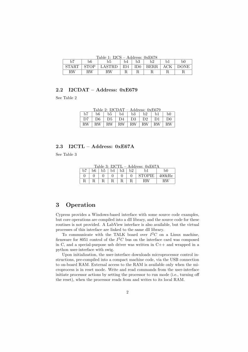
Table 1: I2CS – Address: 0xE678b7 b6 b5 b4 b3 b2 b1 b0
START STOP LASTRD ID1 ID0 BERR ACK DONERW RW RW R R R R R
2.2 I2CDAT – Address: 0xE679
See Table 2
Table 2: I2CDAT – Address: 0xE679b7 b6 b5 b4 b3 b2 b1 b0D7 D6 D5 D4 D3 D2 D1 D0RW RW RW RW RW RW RW RW
2.3 I2CTL – Address: 0xE67A
See Table 3
Table 3: I2CTL – Address: 0xE67Ab7 b6 b5 b4 b3 b2 b1 b00 0 0 0 0 0 STOPIE 400kHzR R R R R R RW RW
3 Operation
Cypress provides a Windows-based interface with some source code examples,but core operations are compiled into a dll library, and the source code for theseroutines is not provided. A LabView interface is also available, but the virtualprocesses of this interface are linked to the same dll library.
To communicate with the TALK board over I2C on a Linux machine,firmware for 8051 control of the I2C bus on the interface card was composedin C, and a special-purpose usb driver was written in C++ and wrapped in apython user-interface with swig.
Upon initialization, the user-interface downloads microprocessor control in-structions, pre-compiled into a compact machine code, via the USB connectionto on-board RAM. External access to the RAM is available only when the mi-croprocess is in reset mode. Write and read commands from the user-interfaceinitiate processor actions by setting the processor to run mode (i.e., turning offthe reset), when the processor reads from and writes to its local RAM.
2
4 Linux Configuration
The Ubuntu 10.04 LTS operating system on a ThinkPad was used as the de-velopment platform. The Ubuntu software repository includes libusb-1.0 andthe Small Device C Compiler (SDCC), a freeware, optimizing ANSI-C com-piler which targets, among other microprocessors, the Intel 8051 (in fact, this isthe default processor target). The repository also makes available the pythondevelopment package, which contains the necessary hearder files to wrap theUSB driver into a functioning python user-interface, and two general purposeEZ-USB programs for downloading pre-compiled instructions into the micro-processor’s memory, cycfx2prog and fxload. Both of these programs were usedand shown to work with the firmware, and elements of each were drawn on toconstruct a special-purpose USB driver.
The components of the Linux I2C package, including libusb-1.0, SDCC,and python development headers, as well as the microprocessor firmware, USBdriver, and user-interface codes were built and shown to run on an SLC5 plat-form, as well.
4.1 Building the Infrastructure on Linux
4.1.1 libusb
Both Ubuntu and Scientific Linux have a libusb library in /usr/lib, but ScientificLinux, at least versions 4 and 5, do not have libusb-1.0, which is standard onUbuntu, and with which the USB driver for this application has been built.Scientific Linux has libusb-0.1, but libusb classes and macros have been modifiedfor verions 1.0. No libusb header file was found on a Scientific Linux machine,which means that the development library was not installed. So, libusb-1.0.8was installed on the Scientific Linux workstation, pcna62gpu1. The package(libusb-1.0.8.tar.bz2) was downloaded into a local directory from
http://sourceforge.net/projects/libusb/files/libusb-1.0/libusb-1.0.8/
and uncompressed with
bunzip2 libusb-1.0.8.tar.bz2
This creates the directory libusb-1.0.8, which contains installation instruc-tions in the file INSTALL. The basic procedure was followed:
./configuremakemake install
This builds the libraries and places them in /usr/local/lib. The header filelibusb.h is placed in /usr/local/include.
3
4.1.2 sdcc
The Small Device C compiler (sdcc) is available as a Debian package, and there-fore readily installed in an Ubuntu system. For SLC systems, rpm packages areavailable from, for example,
http://www.rpmseek.com/
or
http://rpmfind.net/
The rpm package may be installed with yum.Alternatively, Sourceforge privides the latest compressed version (here, for
example, version 3.0.0):
http://sourceforge.net/projects/sdcc/files/sdcc-linux-x86/3.0.0/
sdcc-3.0.0-i386-unknown-linux2.5.tar.bz2/download
The file, once downloaded, is unzipped, and the contents of the resultingdirectory, sdcc, is copied to /usr/local/
cd sdcc
cp -r * /usr/local
This installs sdcc binaries into /usr/local/bin/, header files into /usr/local/share/sdcc/include/,library files into /usr/local/share/sdcc/lib/, and and documentation into /usr/local/share/sdcc/doc/.
4.1.3 swig
The Simplified Wrapper and Interface Generator, swig, is native on Linux plat-forms. In order for the python-wrapped, USB driver to link properly, the di-rectory /usr/local/lib had to be added to the shared library configuration file,/etc/ld.so.conf, and then as root,
ldconfig
4.1.4 python
Of course, python is standard on all Linux platforms, but the header file Python.h,which comes with the development package and is required for swig bundling,is not native to SLC installations. The python development package, python-dev, may be installed with apt-get or yum, and Python.h will be located in/usr/include/python2.6, or whatever the current native version of python.
4

4.2 Initialization
USB in Ubuntu 10.04 is hot-plug plug-and-play. Upon connecting the interfacemodule, the USB port is configured and, as in many Linux environments, reg-istered to the driver usbtest, which permits high-speed, bulk-in/bulk-out tests.In order to communicate with the EZ-USB interface card, this driver must bederegistered (note, for all communications, root privilege must be asserted):
modprobe -r usbtest
5 The Linux Interface Package
5.1 8051 Firmware
The 8051 firmware (see Appendix A) is C code that includes I2C write andread algorithms and a main routine that, when the reset line goes low, inter-prets information written to assigned RAM addresses by the python interfaceto initiate the appropriate (write or read) algorithm. It reads from and writesto to assigned RAM addresses. It is prepared for download by compiling withSDCC, thereby producing an ihex file, which is converted to a binary file withobjcopy.
sdcc -mmcs51 -Iinclude i2ctalkwr.cobjcopy -I ihex -O binary i2ctalkwr.ihx i2ctalkwr.bix
5.2 USB Driver
A USB driver (see Appendix B), written in C++, includes routines for initial-izing the USB port, locating and opening the Cypress device, transferring data,and closing the device. It is compiled into a shared library and wrapped intopython modules.
swig -python -c++ xusb.ig++ -fpic -I/usr/include/python2.6 -c xusb.C xusb wrap.cxxg++ -pthread -shared -lusb-1.0 -o xusb.so xusb.o xusb wrap.o
5.3 User Interface
A user interface was constructed with python (see Appendix C). The pythoncode includes the wrapped USB driver (xusb.py), a core-function definition file(usbl.py), and a user file (i2c.py). Users open a python session and import theuser file, which, in turn, imports the others and then initializes the USB portand downloads the firmware to the 8051. Interactive commands, write, read,writeff, and readtf, are issued from python command lines. These commandsare explained in the next session, User Guide.
5

6 User Guide
Using the device requires root (sudo) privilege.
1. At plug-in, Linux loads a default driver usbtest (issue command dmesgto see), which must be deregistered:
$ modprobe -r usbtest
(check dmesg again to check that usbtest has been deregistered)
2. Change directory to the one containing the I2C package (on pcna62gpu1this is /root/talk/i2c/)
$ cd ‘directory’
3. Start python
$ python
4. At prompt, load USB driver, download 8051 firmware, open device (driverlocates device)
>>> from i2c import *
5. Issue read or write commands. TALK board data transfer is limited to 32bits per read/write interaction
• Write 1-4 bytes with function fn
>>> write(fn,data)
where the data are passed as python lists from highest- to lowest-order bytes, i.e., write(fn,[b1]) or write(fn,[b2,b1]) or write(fn,[b3,b2,b1])or write(fn,[b4,b3,b2,b1]). A python list is an array enclosed in brack-ets: [. . . , . . . , . . . ].
• Read 1-4 bytes with function fn (output sent to stdout)
>>> read(fn,Nbytes)
where Nbytes is the number of bytes (1-4) to read.
• Write data from a file containing a (vertical) list of (long) words withfunction fn
>>> writeff(fn,‘filename’)
’filename’ is a python string, so the single quotes are necessary.
• Read N values and write them to a file as a (vertical) list of (long)words with function fn
>>> readtf(fn,‘filename’,N)
6. Close device
6

>>> x.close()
7. End python session
>>> Control-d (∧d)
7
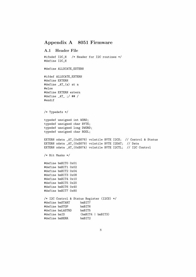
Appendix A 8051 Firmware
A.1 Header File
#ifndef I2C_H /* Header for I2C routines */
#define I2C_H
#define ALLOCATE_EXTERN
#ifdef ALLOCATE_EXTERN
#define EXTERN
#define _AT_(a) at a
#else
#define EXTERN extern
#define _AT_ ;/ ## /
#endif
/* Typedefs */
typedef unsigned int WORD;
typedef unsigned char BYTE;
typedef unsigned long DWORD;
typedef unsigned char BOOL;
EXTERN xdata _AT_(0xE678) volatile BYTE I2CS; // Control & Status
EXTERN xdata _AT_(0xE679) volatile BYTE I2DAT; // Data
EXTERN xdata _AT_(0xE67A) volatile BYTE I2CTL; // I2C Control
/* Bit Masks */
#define bmBIT0 0x01
#define bmBIT1 0x02
#define bmBIT2 0x04
#define bmBIT3 0x08
#define bmBIT4 0x10
#define bmBIT5 0x20
#define bmBIT6 0x40
#define bmBIT7 0x80
/* I2C Control & Status Register (I2CS) */
#define bmSTART bmBIT7
#define bmSTOP bmBIT6
#define bmLASTRD bmBIT5
#define bmID (bmBIT4 | bmBIT3)
#define bmBERR bmBIT2
8

#define bmACK bmBIT1
#define bmDONE bmBIT0
/* I2C Control Register (I2CTL) */
#define bmSTOPIE bmBIT1
#define bm400KHZ bmBIT0
#define bmWRITE 0x00
#define bmREAD 0x01
#define ADDR 0x73 // Peripheral address
#define WADDR ADDR<<1 | bmWRITE // Peripheral address shifted left 1 bit +
// instruction bit 0x00=WRITE
#define RADDR ADDR<<1 | bmREAD // Peripheral address shifted left 1 bit +
// instruction bit 0x01=READ
/* Primitives */
void I2CDelay(WORD Nms);
WORD I2CRead( BYTE fun, BYTE *dat );
WORD I2CWrite( BYTE fun, BYTE *dat );
#endif /* I2C_H */
A.2 Code
A.2.1 Writing
The recipe for writing to a peripheral via the CY7C68013A is:
1. Set START = 1: I2CS bit 7
2. Write 7-bit peripheral address (shifted one bit left) + 1-bit instruction [0= write; 1 = read]: I2CDAT = (0xNN << 1) | 0x00
3. Wait for DONE = 1: I2CS bit 0
4. Return to main program with error code 6= 0 if ACK = 0: I2CS bit 1
5. Load single byte of data: I2DAT = 0xY Y ; repeat steps 3 and 4
6. Repeat step 5 until desired data are sent.
7. Set STOP = 1: I2CS bit 6
8. Wait for STOP = 0: I2CS bit 6
9. Repeat step 4
10. Return to main program with code = 0
9

A.2.2 Reading
The recipe for reading from a peripheral via the CY7C68013A is:
1. Set START = 1: I2CS bit 7
2. Write 7-bit peripheral address (shifted one bit left) + 1-bit instruction [0= write; 1 = read]: I2CDAT = (0xNN << 1) | 0x01
3. Wait for DONE = 1: I2CS bit 0
4. Return to main program with error code 6= 0 if ACK = 0: I2CS bit 1
5. Before reading second-to-last I2CDAT byte, set LASTRD = 1: ISCS bit5
6. Discard first I2CDAT byte (first of 9 SCL pulses); repeat steps 3 and 4
7. Perform step 5, if necessary; read and store I2CDAT byte; repeat steps 3and 4
8. Perform step 5, if necessary; repeat step 7 until second-to-last byte ofdesired data is received.
9. Set STOP = 1: I2CS bit 6
10. Read and store last I2CDAT byte
11. Wait for STOP = 0: I2CS bit 6
12. Repeat step 4
13. Return to main program with code = 0
A.2.3 Code
#include <i2c.h>
/*
* I2CWrite.c
*
* Write 4 bytes to TALK board on I2C bus.
* Send peripheral address (Ox73) and function:
* I2Caddr(7..1)+W(0) Func(7..1)+W Data(32..24)(23..16)(15..8)(7..0)
* 7-bit peripheral address is shifted left 1 bit and read/write instruction bit added
* [0=WRITE; 1=READ]
* Returns 0 on success and >0 on error.
* If ACK is set, the slave acknowledges (OK).
*
* fun: 7-bit function, shifted left 1 bit and read/write instruction bit added
* [0=WRITE; 1=READ]
10
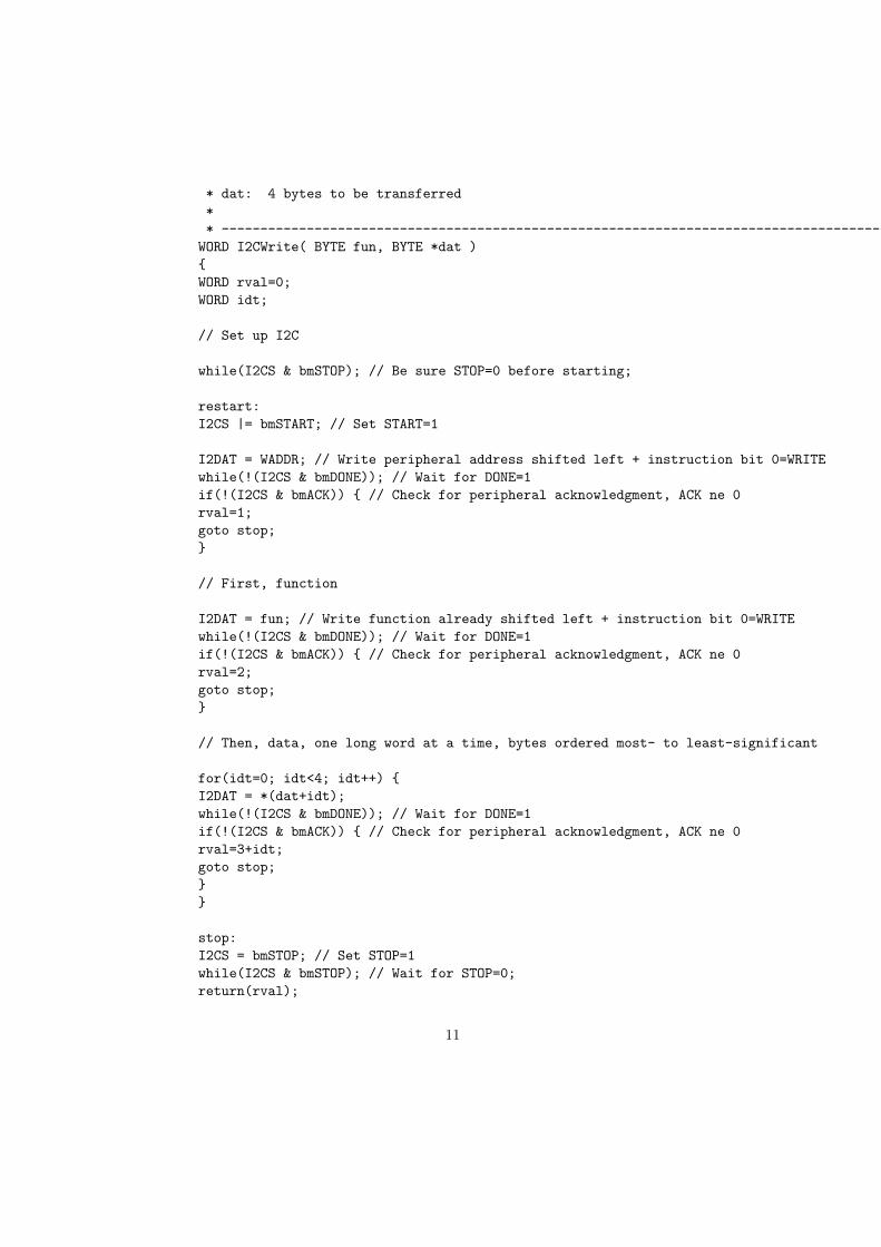
* dat: 4 bytes to be transferred
*
* -------------------------------------------------------------------------------------------------------------------
WORD I2CWrite( BYTE fun, BYTE *dat )
{
WORD rval=0;
WORD idt;
// Set up I2C
while(I2CS & bmSTOP); // Be sure STOP=0 before starting;
restart:
I2CS |= bmSTART; // Set START=1
I2DAT = WADDR; // Write peripheral address shifted left + instruction bit 0=WRITE
while(!(I2CS & bmDONE)); // Wait for DONE=1
if(!(I2CS & bmACK)) { // Check for peripheral acknowledgment, ACK ne 0
rval=1;
goto stop;
}
// First, function
I2DAT = fun; // Write function already shifted left + instruction bit 0=WRITE
while(!(I2CS & bmDONE)); // Wait for DONE=1
if(!(I2CS & bmACK)) { // Check for peripheral acknowledgment, ACK ne 0
rval=2;
goto stop;
}
// Then, data, one long word at a time, bytes ordered most- to least-significant
for(idt=0; idt<4; idt++) {
I2DAT = *(dat+idt);
while(!(I2CS & bmDONE)); // Wait for DONE=1
if(!(I2CS & bmACK)) { // Check for peripheral acknowledgment, ACK ne 0
rval=3+idt;
goto stop;
}
}
stop:
I2CS = bmSTOP; // Set STOP=1
while(I2CS & bmSTOP); // Wait for STOP=0;
return(rval);
11

}
/*
* I2CRead.c
*
* Read 4 bytes from TALK board on I2C bus.
* First, do a write cycle to send peripheral address (Ox73) and function.
* Then, a second cycle to read.
* 7-bit peripheral address is shifted left 1 bit and read/write instruction bit added
* [0=WRITE; 1=READ]
* Returns 0 on success and >0 on error.
* If ACK is set, the slave acknowledges (OK).
*
* fun: 7-bit function, shifted left 1 bit and read/write instruction bit added
* [0=WRITE; 1=READ]
* dat: 4 bytes to be transferred
*
* -------------------------------------------------------------------------------------------------------------------
WORD I2CRead( BYTE fun, BYTE *dat )
{
WORD rval=0;
WORD idt;
BYTE ddum;
// Set up I2C
while(I2CS & bmSTOP); // Be sure STOP=0 before starting;
restart:
I2CS |= bmSTART; // Set START=1
// For TALK board, the function with read bit must first be written
I2DAT = WADDR; // Write 7-bit peripheral address + instruction bit [0=WRITE; 1=READ]
while(!(I2CS & bmDONE)); // Wait for DONE=1
if(!(I2CS & bmACK)) { // Check for peripheral acknowledgment, ACK ne 0
rval=1;
I2CS = bmSTOP; // Set STOP=1
goto stop;
}
// Function
I2DAT = fun;
while(!(I2CS & bmDONE)); // Wait for DONE=1
if(!(I2CS & bmACK)) { // Check for peripheral acknowledgment, ACK ne 0
12

rval=2;
goto stop;
}
// Finish this cycle
I2CS = bmSTOP; // Set STOP=1
while(I2CS & bmSTOP); // Wait for STOP=0;
// Second cycle to read
I2CS |= bmSTART; // Set START=1
// Address again with read bit set
I2DAT = RADDR; // Write 7-bit peripheral address + instruction bit [0=WRITE; 1=READ]
while(!(I2CS & bmDONE)); // Wait for DONE=1
if(!(I2CS & bmACK)) { // Check for peripheral acknowledgment, ACK ne 0
rval=3;
goto stop;
}
// And get and discard first byte
ddum = I2DAT;
while(!(I2CS & bmDONE)); // Wait for DONE=1
// Then, data
for(idt=3; idt>0; idt--) {
*(dat+idt)=I2DAT;
while(!(I2CS & bmDONE)); // Wait for DONE=1
if(idt == 2) (I2CS |= bmLASTRD); // Set LASTRD=1
}
I2CS |= bmSTOP; // Set STOP=1
*(dat) = I2DAT; //Read final byte immediately after setting STOP bit.
stop:
while(I2CS & bmSTOP); // Wait for STOP=0;
return(rval);
}
void main() {
int i;
13

BYTE wr; /* 0=WRITE; 1=READ */
BYTE fun;
BYTE len;
BYTE dat[4];
xdata char *writeread=(xdata char*)0x1000;
xdata char *function=(xdata char*)0x1250;
xdata char *length=(xdata char*)0x1500;
xdata char *wdat=(xdata char*)0x2000;
xdata char *rdat=(xdata char*)0x2500;
wr=*writeread;
fun=*function;
len=*length;
if(wr) { /* 0=WRITE; 1=READ */
I2CRead( fun, dat );
for(i=0;i<4;i++) {
*(rdat+i)=dat[i];
}
}
else {
for(i=3; i>-1; i--) {
if(i>(3-len)) {
dat[i]=*(wdat+3-i);
}
else {
dat[i]=0x00;
}
}
I2CWrite( fun, dat );
}
}
14
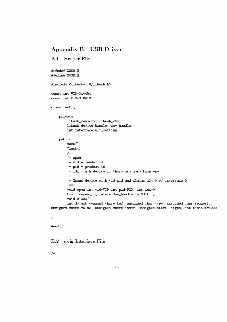
Appendix B USB Driver
B.1 Header File
#ifndef XUSB_H
#define XUSB_H
#include <libusb-1.0/libusb.h>
const int VID=0x04b4;
const int PID=0x8613;
class xusb {
private:
libusb_context* libusb_ctx;
libusb_device_handle* dev_handle;
int interface,alt_setting;
public:
xusb();
~xusb();
/**
* open
* vid = vendor id
* pid = product id
* idx = nth device if there are more than one.
*
* Opens device with vid,pid and claims alt 0 of interface 0
**/
void open(int vid=VID,int pid=PID, int idx=0);
bool isopen() { return dev_handle != NULL; }
void close();
int do_usb_command(char* buf, unsigned char type, unsigned char request,
unsigned short value, unsigned short index, unsigned short length, int timeout=1000 );
};
#endif
B.2 swig Interface File
/*
15

xusb.i
swig interface module
*/
%module xusb
%include "cdata.i"
%apply (char* STRING, int LENGTH) { (char* buf, int size) }
%{
/* include header in the wrapper code */
#include "xusb.h"
%}
/* parse header file */
%include "xusb.h"
B.3 Code
/* xusb.C
USB driver
*/
#include <cstdio>
#include <cassert>
#include "xusb.h"
#define CHECK_OPEN(r) if (!dev_handle) {\
printf ( "Device not opened.\n" ); \
return r;\
}
xusb::xusb():dev_handle(NULL) {
int rv=libusb_init(&libusb_ctx);
assert(!rv);
libusb_set_debug(libusb_ctx,0);
}
xusb::~xusb() {
if (isopen()) close();
16

libusb_exit(libusb_ctx);
}
void xusb::open(int vid,int pid,int idx) {
libusb_device **list;
int devices = libusb_get_device_list( libusb_ctx, &list );
int cur_idx=0;
for ( int i=0;i<devices;++i) {
libusb_device_descriptor dscr;
if ( !libusb_get_device_descriptor ( list[i], &dscr ) ) {
if ( dscr.idVendor == vid && dscr.idProduct == pid ) {
if ( idx == cur_idx++ ) {
int rv = libusb_open( list[i], &dev_handle);
if (!rv) {
rv=libusb_claim_interface(dev_handle,0);
if (!rv) {
interface=0;
rv=libusb_set_interface_alt_setting(dev_handle,0,0);
if (rv) {
libusb_close(dev_handle);
dev_handle=NULL;
}
alt_setting=0;
} else {
libusb_close(dev_handle);
dev_handle=NULL;
}
} else {
printf ( "Unable to open device idx: %d, ret: %d\n", idx, rv );
}
}
}
}
}
CHECK_OPEN()
libusb_free_device_list(list,1);
}
void xusb::close() {
CHECK_OPEN()
libusb_release_interface(dev_handle,interface);
libusb_close(dev_handle);
dev_handle=NULL;
17
interface=0;alt_setting=0;
}
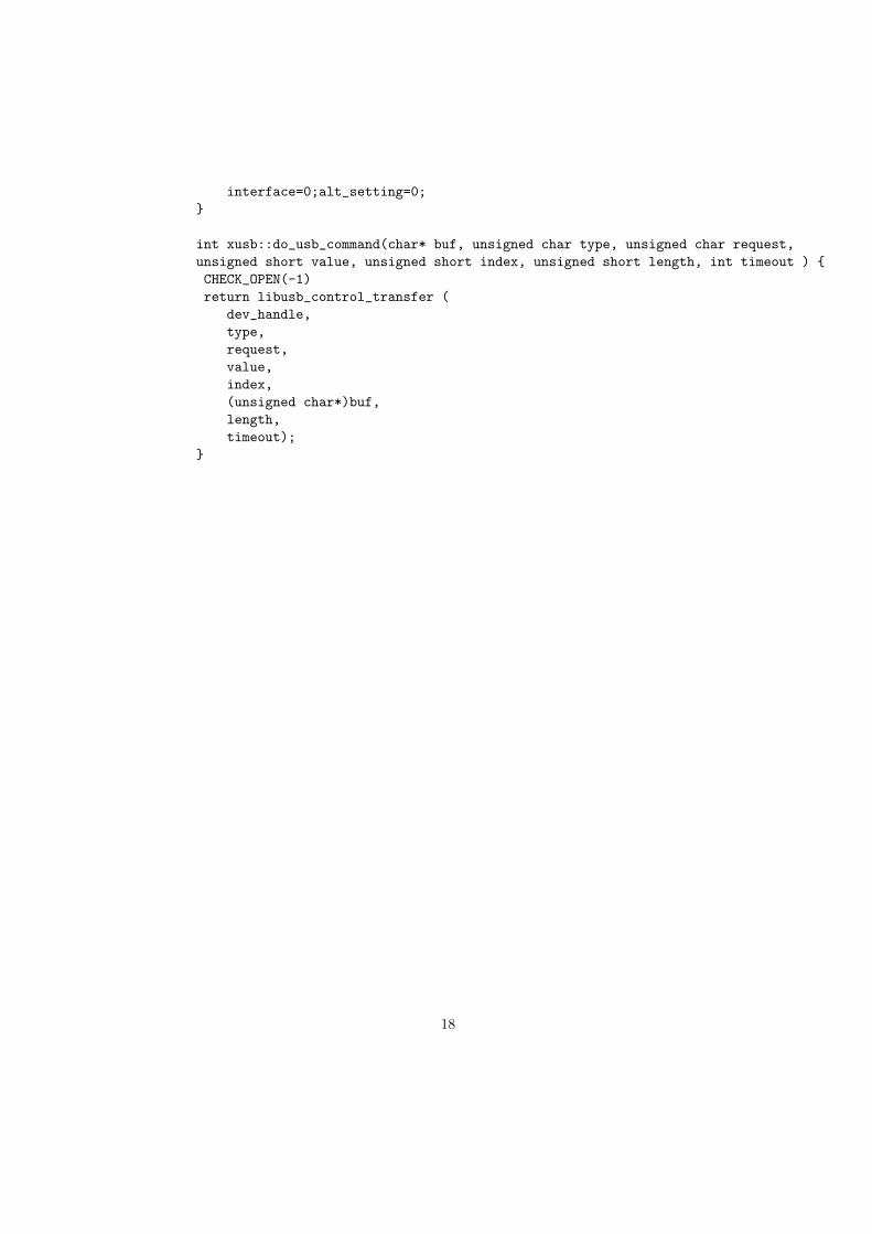
int xusb::do_usb_command(char* buf, unsigned char type, unsigned char request,
unsigned short value, unsigned short index, unsigned short length, int timeout ) {
CHECK_OPEN(-1)
return libusb_control_transfer (
dev_handle,
type,
request,
value,
index,
(unsigned char*)buf,
length,
timeout);
}
18

Appendix C User Interface
C.1 usbl.py
from time import sleep
import xusb
x=xusb.xusb()
# use this functions 1st
def openxusb(vid=0x04b4,pid=0x8613,idx=0):
x.open(vid,pid,idx)
def reset_device(reset):
print reset and "Put device in reset" or "Set device to run"
write_ram (0xe600,reset and chr(0x01) or chr(0x00), 1)
def write_ram(addr,data,length):
ret=x.do_usb_command( data,
0x40,
0xa0,
addr, 0, length )
if (ret>0):
print "wrote %d bytes" % ret
else:
print "Error writing: %d" % ret
return
def read_ram(addr,data,length):
ret=x.do_usb_command( data,
0xc0,
0xa0,
addr, 0, length )
if (ret>0):
print "read %d bytes" % ret
else:
print "Error: %d" % ret
return
def load_bix(filename):
"""
Use this function to reset your firmware. You’ll need to reopen the device afterward.
"""
reset_device(True)
19

bix=open(filename).read()
print "loading bix file of length: %d" % len(bix)
write_ram( 0, bix,len(bix) );
C.2 i2c.py
from xusbl import *
openxusb()
load_bix(’i2ctalkwr.bix’)
def write(fun,dat):
if(len(dat)>4): # Check length
print "Limit 4 Bytes"
return
dat.reverse() # Order bytes so loaded 32...0
reset_device(True) # Set 8051 into reset mode; necessary to write to RAM
write_ram(0x1000,chr(0),1) # Indicate writing (0=WRITE; 1=READ)
write_ram(0x1250,chr(fun<<1),1) # Function shifted left 1 bit +
instruction bit (0=WRITE; 1=READ)
write_ram(0x1500,chr(len(dat)),1) # Length of data list
if(len(dat)>0):
cdat=chr(0) # Convert data list entries to char; here initializing character string
for item in dat: # Do conversion
cdat+=chr(item)
cdat=cdat[1:] # Get rid of initialization character (must be a smarter way...)
write_ram(0x2000,cdat,len(dat)) # Send data
reset_device(False) # Set 8051 into run mode
sleep(.5)
reset_device(True) # Set 8051 into reset mode
def read(fun,num):
global gdat
if(num<1 or num>4): # Check length
print "Read 1-4 bytes"
return
reset_device(True) # Set 8051 into reset mode
write_ram(0x1000,chr(1),1) # Indicate writing (0=WRITE; 1=READ)
write_ram(0x1250,chr(fun<<1 | 0x01),1) # Function shifted left 1 bit +
instruction bit (0=WRITE; 1=READ)
reset_device(False) # Set 8051 into run mode
sleep(1)
reset_device(True) # Set 8051 into reset mode; necessary to read from RAM
cdat=4*chr(0) # Data entries as char; here initializing character string
read_ram(0x2500,cdat,num) # Get data
20

dat=[]
for item in cdat: # Print data
dat.append(ord(item))
gdat=dat
for i in range(num):
print dat[num-1-i], hex(dat[num-1-i])
def writeff(fun,fnam):
f=open(fnam) # Open file ’filename’
for line in f.readlines(): # Step through each line of the file
dat=[] # Initialize 4-byte list
num=int(line.strip(’\n’),16) # Strip off carriage return/line feed from file entries and turn into integer
for i in range(24,-8,-8): # Turn word into list of 4 Bytes, highest-order bytes first
dat.append(num>>i&0xff) # Append to list
write(fun,dat) # Write one word (4 Bytes) at a time
f.close() # Close file
def readtf(fun,fnam,nwords):
global gdat
f=open(fnam,’w’) # Open file ’filename’ in write mode
for i in range(nwords): # Read nwords words
read(fun,4) # Read one word (4 Bytes) at a time
num=0 # Initialize word
for i in range(24,-8,-8): # Turn list of 4 Bytes into word, beginning with highest-order byte
num|=gdat[i/8]<<i # Mask bit-shifted bytes onto word
sn=str(hex(num)) # Only strings written to file
f.write(sn+’\n’) # Right value to file
f.close() # Close file
def close():
x.close()
21