i2c/spi lcd backpack - adafruit learning system
TRANSCRIPT
i2c/SPI LCD Backpack
Created by lady ada
https://learn.adafruit.com/i2c-spi-lcd-backpack
Last updated on 2021-11-15 05:51:06 PM EST
©Adafruit Industries Page 1 of 26
3
4
4
5
5
5
6
8
10
10
11
12
13
14
15
16
17
17
19
19
20
21
21
21
22
22
24
25
25
25
25
25
Table of Contents
Overview
Which LCD to Use?
• Wait - the backpack has 16 holes, but my LCD only has 14 pins!
Assembly
• Parts Check
• Terminal Blocks
• Prepare LCD
• Attach LCD
• My LCD only has 14 pins. Which holes do I use?
Arduino I2C Use
• Install Adafruit_LiquidCrystal
• Load Demo
• Changing the I2C Address
Arduino SPI Use
• Install Adafruit_LiquidCrystal
• Load Demo
Python & CircuitPython
• CircuitPython Microcontroller Wiring
• Python Computer Wiring
• CircuitPython Installation of CharLCD Library
• Python Installation of CharLCD Library
• Python & CircuitPython Usage
• I2C Initialization
• SPI Initialization
• Backpack Usage
• Full Example Code
Python Docs
Downloads
•
• Hardware files
• Schematic
• Fabrication Print
©Adafruit Industries Page 2 of 26
Overview
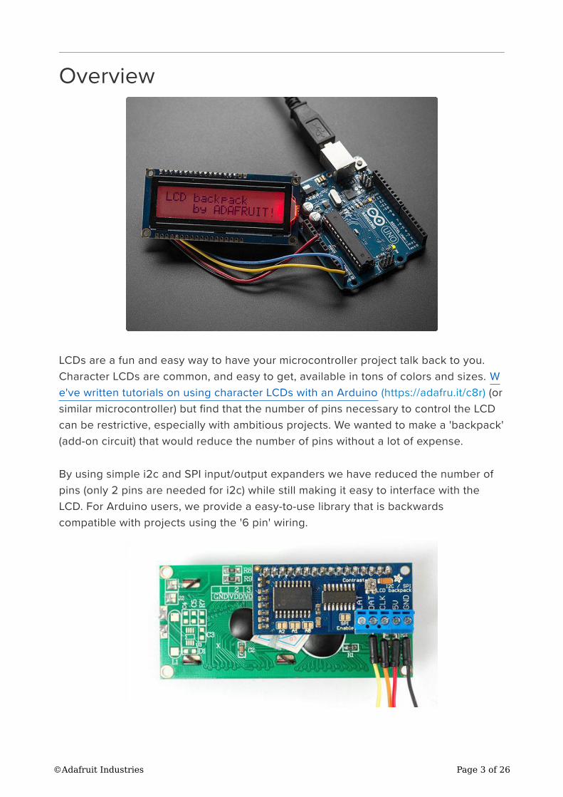
LCDs are a fun and easy way to have your microcontroller project talk back to you.
Character LCDs are common, and easy to get, available in tons of colors and sizes. W
e've written tutorials on using character LCDs with an Arduino (https://adafru.it/c8r) (or
similar microcontroller) but find that the number of pins necessary to control the LCD
can be restrictive, especially with ambitious projects. We wanted to make a 'backpack'
(add-on circuit) that would reduce the number of pins without a lot of expense.
By using simple i2c and SPI input/output expanders we have reduced the number of
pins (only 2 pins are needed for i2c) while still making it easy to interface with the
LCD. For Arduino users, we provide a easy-to-use library that is backwards
compatible with projects using the '6 pin' wiring.
©Adafruit Industries Page 3 of 26
For advanced users, this project can be used for general purpose I/O expansion, the
MCP23008 has 8 i/o pins (7 are connected) with optional pullups, the SPI 74HC595
has 7 outputs.
Assembled and tested backpacks are available for purchase for only $10 in the
Adafruit shop!
Which LCD to Use?
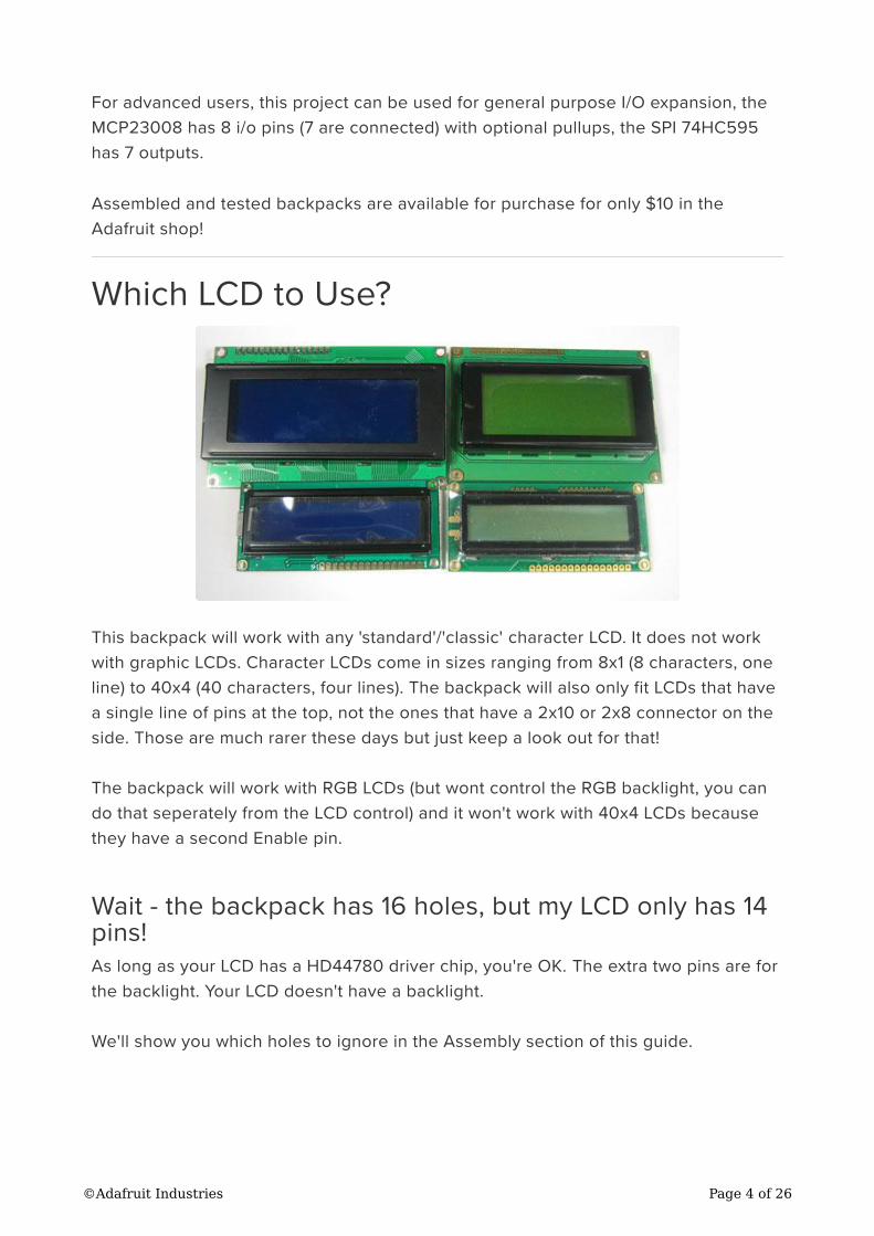
This backpack will work with any 'standard'/'classic' character LCD. It does not work
with graphic LCDs. Character LCDs come in sizes ranging from 8x1 (8 characters, one
line) to 40x4 (40 characters, four lines). The backpack will also only fit LCDs that have
a single line of pins at the top, not the ones that have a 2x10 or 2x8 connector on the
side. Those are much rarer these days but just keep a look out for that!
The backpack will work with RGB LCDs (but wont control the RGB backlight, you can
do that seperately from the LCD control) and it won't work with 40x4 LCDs because
they have a second Enable pin.
Wait - the backpack has 16 holes, but my LCD only has 14
pins!
As long as your LCD has a HD44780 driver chip, you're OK. The extra two pins are for
the backlight. Your LCD doesn't have a backlight.
We'll show you which holes to ignore in the Assembly section of this guide.
©Adafruit Industries Page 4 of 26
Assembly
Putting together the backpack onto an LCD is a quick process, and should take only a
few minutes with a soldering iron.
Parts Check
Verify you have everything in the bag, there should be an assembled and tested PCB,
a 2-pin and 3-pin 3.5mm terminal block. The backpack does not come with header or
an LCD.
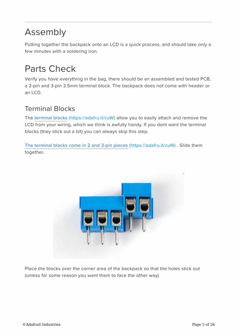
Terminal Blocks
The terminal blocks (https://adafru.it/cuW) allow you to easily attach and remove the
LCD from your wiring, which we think is awfully handy. If you dont want the terminal
blocks (they stick out a bit) you can always skip this step.
The terminal blocks come in 2 and 3-pin pieces (https://adafru.it/cuW) . Slide them
together.
Place the blocks over the corner area of the backpack so that the holes stick out
(unless for some reason you want them to face the other way)
©Adafruit Industries Page 5 of 26
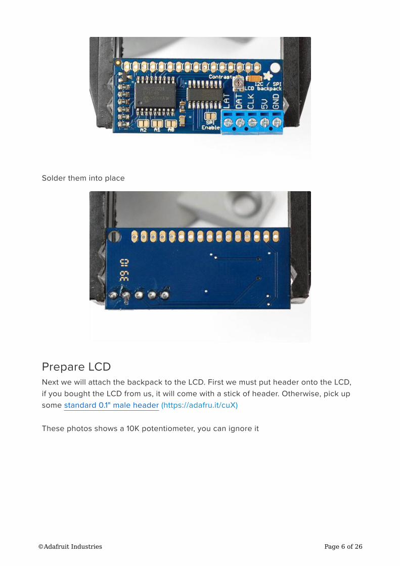
Solder them into place
Prepare LCD
Next we will attach the backpack to the LCD. First we must put header onto the LCD,
if you bought the LCD from us, it will come with a stick of header. Otherwise, pick up
some standard 0.1" male header (https://adafru.it/cuX)
These photos shows a 10K potentiometer, you can ignore it
©Adafruit Industries Page 6 of 26
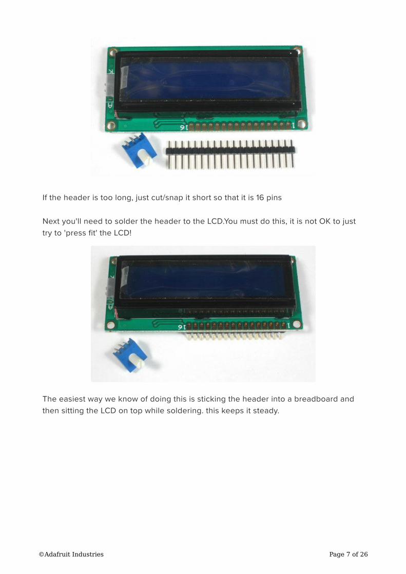
If the header is too long, just cut/snap it short so that it is 16 pins
Next you'll need to solder the header to the LCD.You must do this, it is not OK to just
try to 'press fit' the LCD!
The easiest way we know of doing this is sticking the header into a breadboard and
then sitting the LCD on top while soldering. this keeps it steady.
©Adafruit Industries Page 7 of 26

Attach LCD
Now we will attach the backpack. We will show how to do this in a permanent fashion.
If you think you would like to remove and replace the LCD at some time, you can
use a piece of 16-pin long 0.1" female header (https://adafru.it/cuX) as a socket but be
aware it will stick out a lot.
There are two options, you can tuck the backpack behind the LCD
Or solder it so it's to the side, this way it's thinner.
Make sure that you line up pin 1 of the backpack with pin 1 of the display. Pin 1 is
on the right side of the backpack closest to the Adafruit logo. Pin one of the
display should be marked. When correctly installed, the blue terminal block will
be close to the edge of the display.
©Adafruit Industries Page 8 of 26
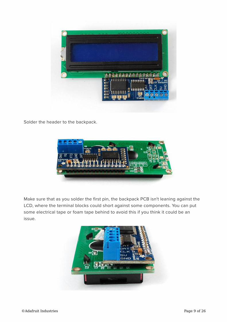
Solder the header to the backpack.
Make sure that as you solder the first pin, the backpack PCB isn't leaning against the
LCD, where the terminal blocks could short against some components. You can put
some electrical tape or foam tape behind to avoid this if you think it could be an
issue.
©Adafruit Industries Page 9 of 26
That's it!
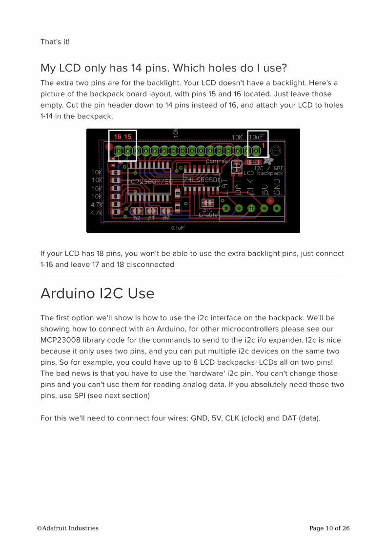
My LCD only has 14 pins. Which holes do I use?
The extra two pins are for the backlight. Your LCD doesn't have a backlight. Here's a
picture of the backpack board layout, with pins 15 and 16 located. Just leave those
empty. Cut the pin header down to 14 pins instead of 16, and attach your LCD to holes
1-14 in the backpack.
If your LCD has 18 pins, you won't be able to use the extra backlight pins, just connect
1-16 and leave 17 and 18 disconnected
Arduino I2C Use
The first option we'll show is how to use the i2c interface on the backpack. We'll be
showing how to connect with an Arduino, for other microcontrollers please see our
MCP23008 library code for the commands to send to the i2c i/o expander. I2c is nice
because it only uses two pins, and you can put multiple i2c devices on the same two
pins. So for example, you could have up to 8 LCD backpacks+LCDs all on two pins!
The bad news is that you have to use the 'hardware' i2c pin. You can't change those
pins and you can't use them for reading analog data. If you absolutely need those two
pins, use SPI (see next section)
For this we'll need to connnect four wires: GND, 5V, CLK (clock) and DAT (data).
©Adafruit Industries Page 10 of 26
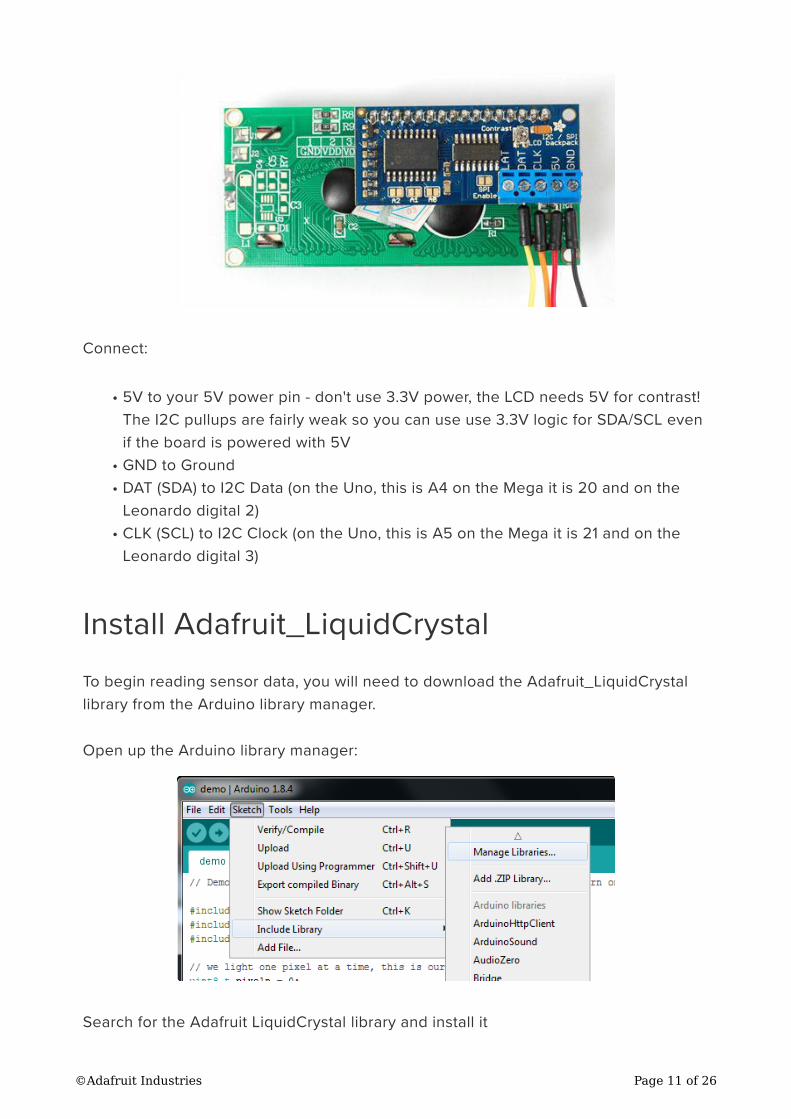
Connect:
5V to your 5V power pin - don't use 3.3V power, the LCD needs 5V for contrast!
The I2C pullups are fairly weak so you can use use 3.3V logic for SDA/SCL even
if the board is powered with 5V
GND to Ground
DAT (SDA) to I2C Data (on the Uno, this is A4 on the Mega it is 20 and on the
Leonardo digital 2)
CLK (SCL) to I2C Clock (on the Uno, this is A5 on the Mega it is 21 and on the
Leonardo digital 3)
Install Adafruit_LiquidCrystal
To begin reading sensor data, you will need to download the Adafruit_LiquidCrystal
library from the Arduino library manager.
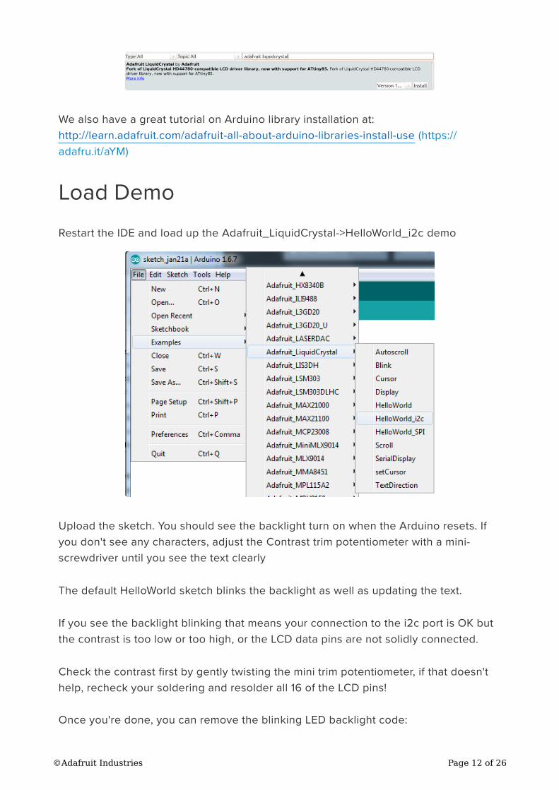
Open up the Arduino library manager:
Search for the Adafruit LiquidCrystal library and install it
•
•
•
•
©Adafruit Industries Page 11 of 26
We also have a great tutorial on Arduino library installation at:
http://learn.adafruit.com/adafruit-all-about-arduino-libraries-install-use (https://
adafru.it/aYM)
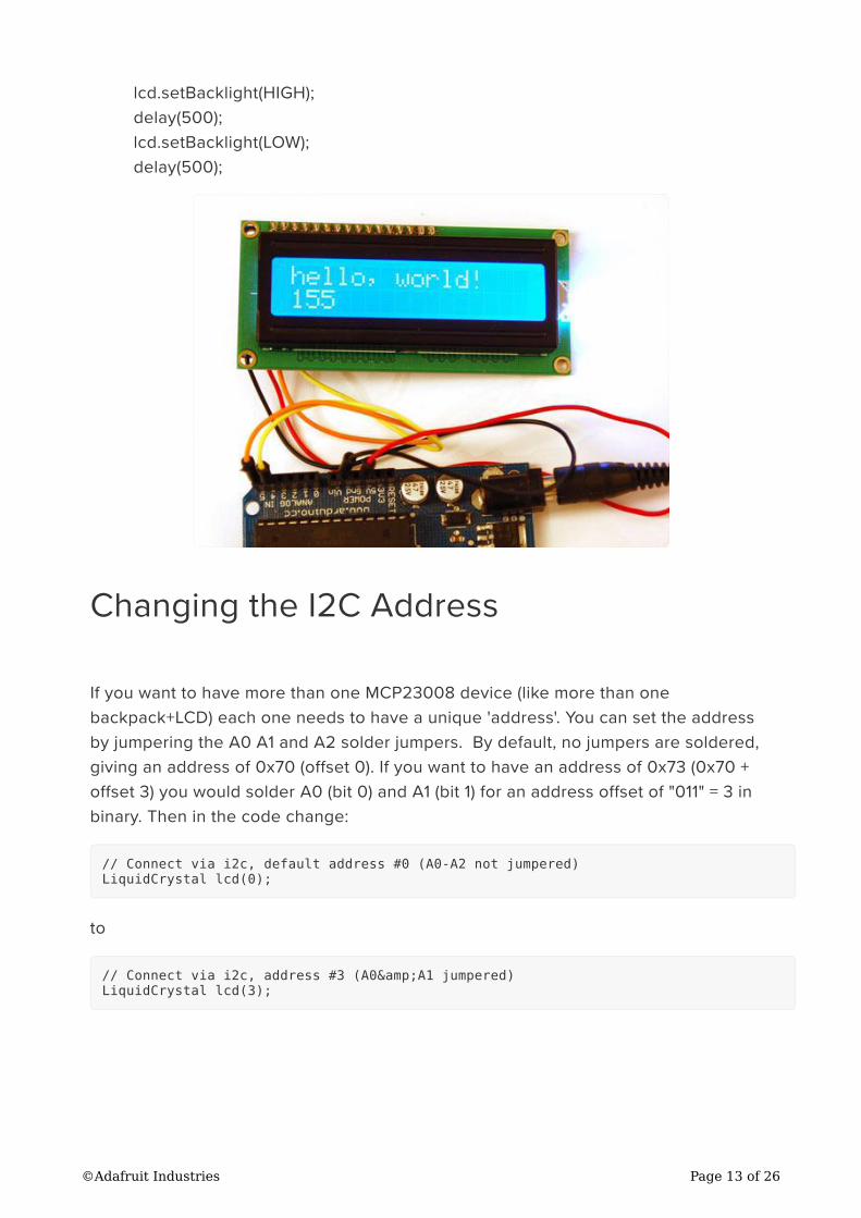
Load Demo
Restart the IDE and load up the Adafruit_LiquidCrystal->HelloWorld_i2c demo
Upload the sketch. You should see the backlight turn on when the Arduino resets. If
you don't see any characters, adjust the Contrast trim potentiometer with a mini-
screwdriver until you see the text clearly
The default HelloWorld sketch blinks the backlight as well as updating the text.
If you see the backlight blinking that means your connection to the i2c port is OK but
the contrast is too low or too high, or the LCD data pins are not solidly connected.
Check the contrast first by gently twisting the mini trim potentiometer, if that doesn't
help, recheck your soldering and resolder all 16 of the LCD pins!
Once you're done, you can remove the blinking LED backlight code:
©Adafruit Industries Page 12 of 26
lcd.setBacklight(HIGH);
delay(500);
lcd.setBacklight(LOW);
delay(500);
Changing the I2C Address
If you want to have more than one MCP23008 device (like more than one
backpack+LCD) each one needs to have a unique 'address'. You can set the address
by jumpering the A0 A1 and A2 solder jumpers. By default, no jumpers are soldered,
giving an address of 0x70 (offset 0). If you want to have an address of 0x73 (0x70 +
offset 3) you would solder A0 (bit 0) and A1 (bit 1) for an address offset of "011" = 3 in
binary. Then in the code change:
// Connect via i2c, default address #0 (A0-A2 not jumpered)
LiquidCrystal lcd(0);
to
// Connect via i2c, address #3 (A0&A1 jumpered)
LiquidCrystal lcd(3);
©Adafruit Industries Page 13 of 26
Arduino SPI Use
Another option for connecting is to use SPI, which is a simpler protocol. The good
news about SPI is that its very simple and you can use any 3 pins to connect. You can
share the data and clock pins with another device as long as they remain outputs, the
latch pin should only be used for the backpack. So if you wanted 3 LCDs, for example,
they would all have the same data and clock pins, but the latch pin would be different,
for 5 pins total
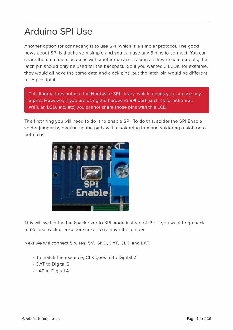
The first thing you will need to do is to enable SPI. To do this, solder the SPI Enable
solder jumper by heating up the pads with a soldering iron and soldering a blob onto
both pins:
This will switch the backpack over to SPI mode instead of i2c. If you want to go back
to i2c, use wick or a solder sucker to remove the jumper
Next we will connect 5 wires, 5V, GND, DAT, CLK, and LAT.
To match the example, CLK goes to to Digital 2
DAT to Digital 3,
LAT to Digital 4
This library does not use the Hardware SPI library, which means you can use any
3 pins! However, if you are using the hardware SPI port (such as for Ethernet,
WiFi, an LCD, etc. etc) you cannot share those pins with this LCD!
•
•
•
©Adafruit Industries Page 14 of 26
Once we have the example sketch running you can of course change these to
anything you'd like
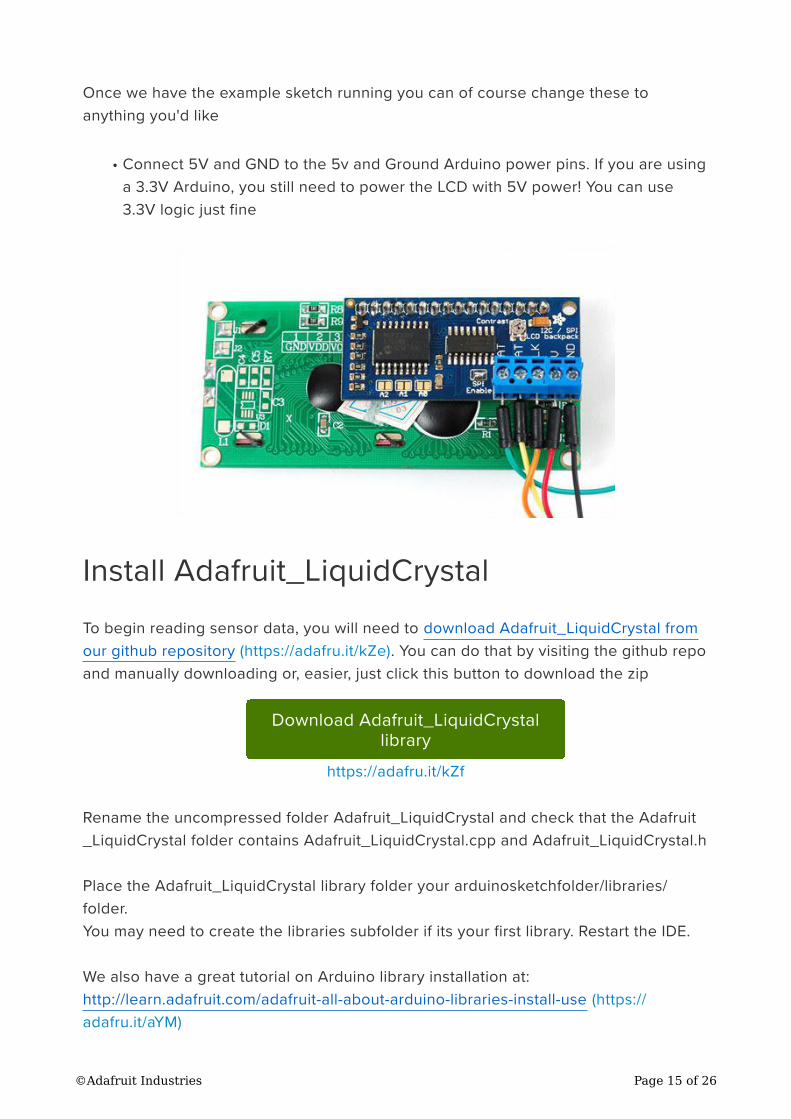
Connect 5V and GND to the 5v and Ground Arduino power pins. If you are using
a 3.3V Arduino, you still need to power the LCD with 5V power! You can use
3.3V logic just fine
Install Adafruit_LiquidCrystal
To begin reading sensor data, you will need to download Adafruit_LiquidCrystal from
our github repository (https://adafru.it/kZe). You can do that by visiting the github repo
and manually downloading or, easier, just click this button to download the zip
Download Adafruit_LiquidCrystal
library
https://adafru.it/kZf
Rename the uncompressed folder Adafruit_LiquidCrystal and check that the Adafruit
_LiquidCrystal folder contains Adafruit_LiquidCrystal.cpp and Adafruit_LiquidCrystal.h
Place the Adafruit_LiquidCrystal library folder your arduinosketchfolder/libraries/
folder.
You may need to create the libraries subfolder if its your first library. Restart the IDE.
We also have a great tutorial on Arduino library installation at:
http://learn.adafruit.com/adafruit-all-about-arduino-libraries-install-use (https://
adafru.it/aYM)
•
©Adafruit Industries Page 15 of 26
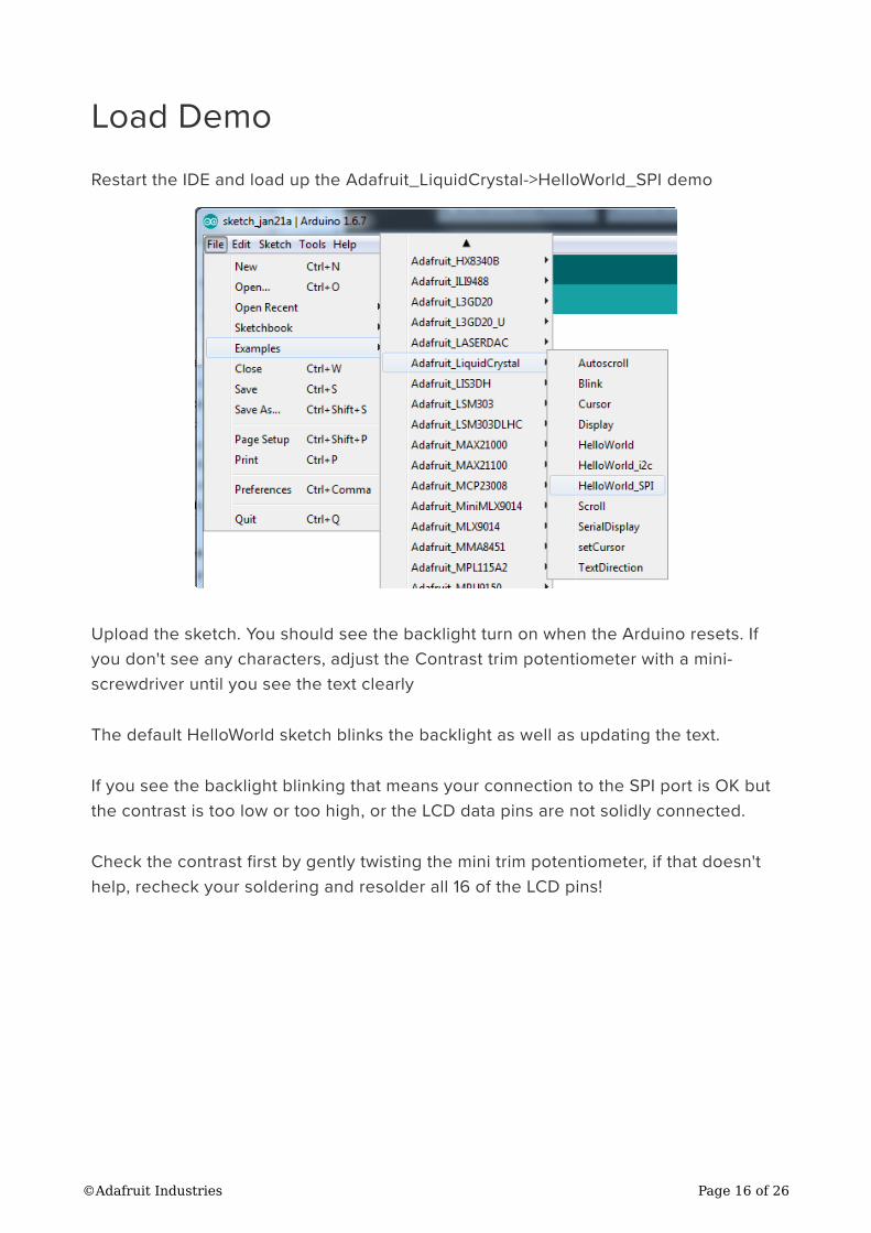
Load Demo
Restart the IDE and load up the Adafruit_LiquidCrystal->HelloWorld_SPI demo
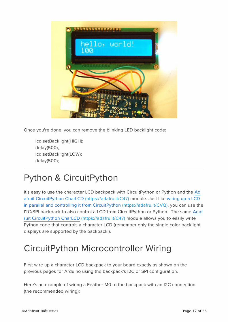
Upload the sketch. You should see the backlight turn on when the Arduino resets. If
you don't see any characters, adjust the Contrast trim potentiometer with a mini-
screwdriver until you see the text clearly
The default HelloWorld sketch blinks the backlight as well as updating the text.
If you see the backlight blinking that means your connection to the SPI port is OK but
the contrast is too low or too high, or the LCD data pins are not solidly connected.
Check the contrast first by gently twisting the mini trim potentiometer, if that doesn't
help, recheck your soldering and resolder all 16 of the LCD pins!
©Adafruit Industries Page 16 of 26
Once you're done, you can remove the blinking LED backlight code:
lcd.setBacklight(HIGH);
delay(500);
lcd.setBacklight(LOW);
delay(500);
Python & CircuitPython
It's easy to use the character LCD backpack with CircuitPython or Python and the Ad
afruit CircuitPython CharLCD (https://adafru.it/C47) module. Just like wiring up a LCD
in parallel and controlling it from CircuitPython (https://adafru.it/CVQ), you can use the
I2C/SPI backpack to also control a LCD from CircuitPython or Python. The same Adaf
ruit CircuitPython CharLCD (https://adafru.it/C47) module allows you to easily write
Python code that controls a character LCD (remember only the single color backlight
displays are supported by the backpack!).
CircuitPython Microcontroller Wiring
First wire up a character LCD backpack to your board exactly as shown on the
previous pages for Arduino using the backpack's I2C or SPI configuration.
Here's an example of wiring a Feather M0 to the backpack with an I2C connection
(the recommended wiring):
©Adafruit Industries Page 17 of 26
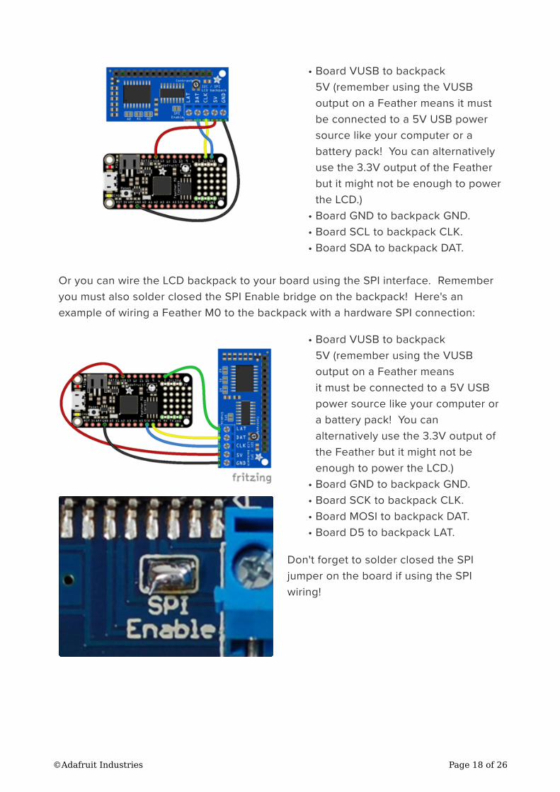
Board VUSB to backpack
5V (remember using the VUSB
output on a Feather means it must
be connected to a 5V USB power
source like your computer or a
battery pack! You can alternatively
use the 3.3V output of the Feather
but it might not be enough to power
the LCD.)
Board GND to backpack GND.
Board SCL to backpack CLK.
Board SDA to backpack DAT.
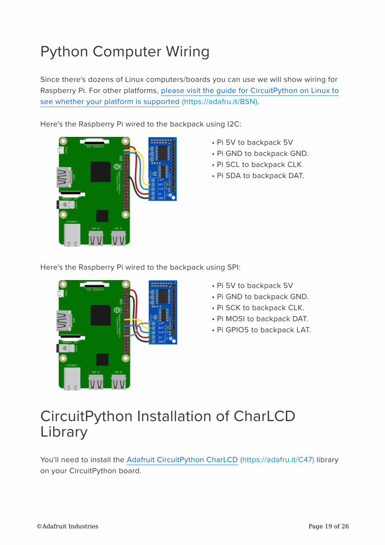
Or you can wire the LCD backpack to your board using the SPI interface. Remember
you must also solder closed the SPI Enable bridge on the backpack! Here's an
example of wiring a Feather M0 to the backpack with a hardware SPI connection:
Board VUSB to backpack
5V (remember using the VUSB
output on a Feather means
it must be connected to a 5V USB
power source like your computer or
a battery pack! You can
alternatively use the 3.3V output of
the Feather but it might not be
enough to power the LCD.)
Board GND to backpack GND.
Board SCK to backpack CLK.
Board MOSI to backpack DAT.
Board D5 to backpack LAT.
Don't forget to solder closed the SPI
jumper on the board if using the SPI
wiring!
•
•
•
•
•
•
•
•
•
©Adafruit Industries Page 18 of 26
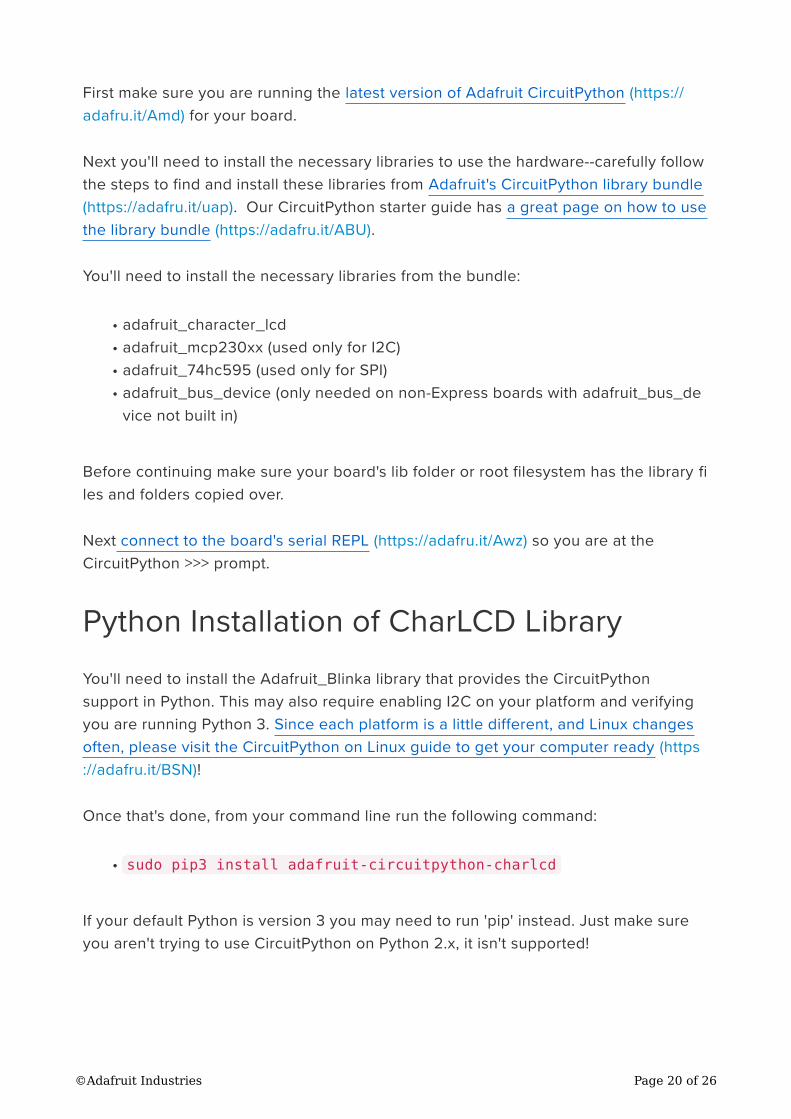
Python Computer Wiring
Since there's dozens of Linux computers/boards you can use we will show wiring for
Raspberry Pi. For other platforms, please visit the guide for CircuitPython on Linux to
see whether your platform is supported (https://adafru.it/BSN).
Here's the Raspberry Pi wired to the backpack using I2C:
Pi 5V to backpack 5V
Pi GND to backpack GND.
Pi SCL to backpack CLK.
Pi SDA to backpack DAT.
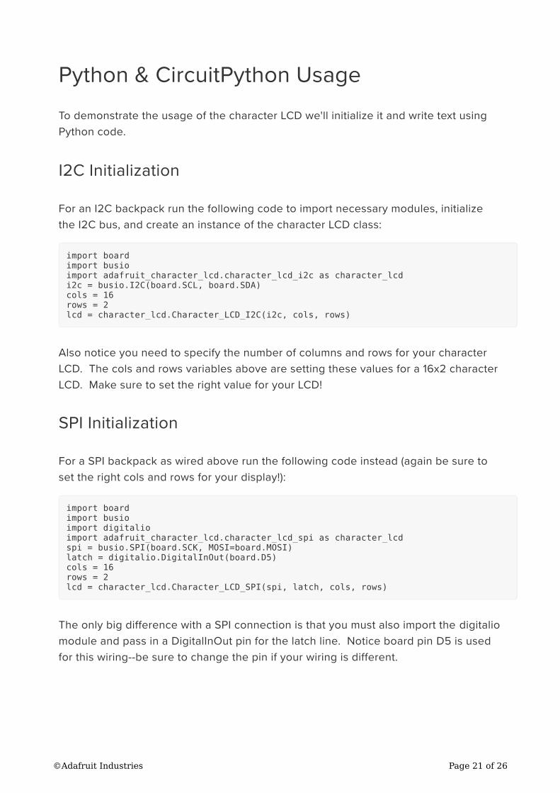
Here's the Raspberry Pi wired to the backpack using SPI:
Pi 5V to backpack 5V
Pi GND to backpack GND.
Pi SCK to backpack CLK.
Pi MOSI to backpack DAT.
Pi GPIO5 to backpack LAT.
CircuitPython Installation of CharLCD
Library
You'll need to install the Adafruit CircuitPython CharLCD (https://adafru.it/C47) library
on your CircuitPython board.
•
•
•
•
•
•
•
•
•
©Adafruit Industries Page 19 of 26
First make sure you are running the latest version of Adafruit CircuitPython (https://
adafru.it/Amd) for your board.
Next you'll need to install the necessary libraries to use the hardware--carefully follow
the steps to find and install these libraries from Adafruit's CircuitPython library bundle
(https://adafru.it/uap). Our CircuitPython starter guide has a great page on how to use
the library bundle (https://adafru.it/ABU).
You'll need to install the necessary libraries from the bundle:
adafruit_character_lcd
adafruit_mcp230xx (used only for I2C)
adafruit_74hc595 (used only for SPI)
adafruit_bus_device (only needed on non-Express boards with adafruit_bus_de
vice not built in)
Before continuing make sure your board's lib folder or root filesystem has the library fi
les and folders copied over.
Next connect to the board's serial REPL (https://adafru.it/Awz) so you are at the
CircuitPython >>> prompt.
Python Installation of CharLCD Library
You'll need to install the Adafruit_Blinka library that provides the CircuitPython
support in Python. This may also require enabling I2C on your platform and verifying
you are running Python 3. Since each platform is a little different, and Linux changes
often, please visit the CircuitPython on Linux guide to get your computer ready (https
://adafru.it/BSN)!
Once that's done, from your command line run the following command:
sudo pip3 install adafruit-circuitpython-charlcd
If your default Python is version 3 you may need to run 'pip' instead. Just make sure
you aren't trying to use CircuitPython on Python 2.x, it isn't supported!
•
•
•
•
•
©Adafruit Industries Page 20 of 26
Python & CircuitPython Usage
To demonstrate the usage of the character LCD we'll initialize it and write text using
Python code.
I2C Initialization
For an I2C backpack run the following code to import necessary modules, initialize
the I2C bus, and create an instance of the character LCD class:
import board
import busio
import adafruit_character_lcd.character_lcd_i2c as character_lcd
i2c = busio.I2C(board.SCL, board.SDA)
cols = 16
rows = 2
lcd = character_lcd.Character_LCD_I2C(i2c, cols, rows)
Also notice you need to specify the number of columns and rows for your character
LCD. The cols and rows variables above are setting these values for a 16x2 character
LCD. Make sure to set the right value for your LCD!
SPI Initialization
For a SPI backpack as wired above run the following code instead (again be sure to
set the right cols and rows for your display!):
import board
import busio
import digitalio
import adafruit_character_lcd.character_lcd_spi as character_lcd
spi = busio.SPI(board.SCK, MOSI=board.MOSI)
latch = digitalio.DigitalInOut(board.D5)
cols = 16
rows = 2
lcd = character_lcd.Character_LCD_SPI(spi, latch, cols, rows)
The only big difference with a SPI connection is that you must also import the digitalio
module and pass in a DigitalInOut pin for the latch line. Notice board pin D5 is used
for this wiring--be sure to change the pin if your wiring is different.
©Adafruit Industries Page 21 of 26
Backpack Usage
Now you're ready to start writing text and characters on the display! The usage of the
LCD class is exactly the same as shown in the parallel LCD wiring guide (https://
adafru.it/CVQ). Be sure to check out that guide (https://adafru.it/CVQ) for a complete
discussion of LCD usage.
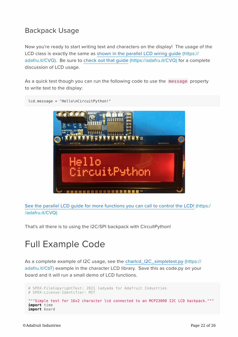
As a quick test though you can run the following code to use the message property
to write text to the display:
lcd.message = "Hello\nCircuitPython!"
See the parallel LCD guide for more functions you can call to control the LCD! (https:/
/adafru.it/CVQ)
That's all there is to using the I2C/SPI backpack with CircuitPython!
Full Example Code
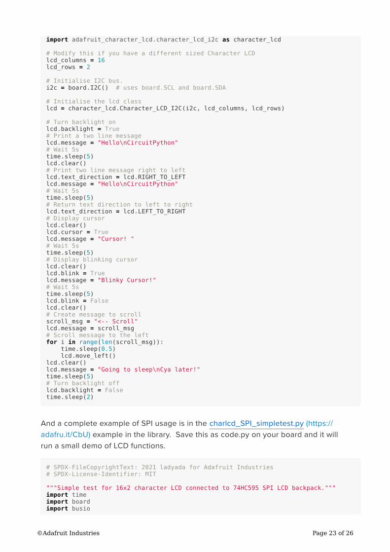
As a complete example of I2C usage, see the charlcd_I2C_simpletest.py (https://
adafru.it/CbT) example in the character LCD library. Save this as code.py on your
board and it will run a small demo of LCD functions.
# SPDX-FileCopyrightText: 2021 ladyada for Adafruit Industries
# SPDX-License-Identifier: MIT
"""Simple test for 16x2 character lcd connected to an MCP23008 I2C LCD backpack."""
import time
import board
©Adafruit Industries Page 22 of 26
import adafruit_character_lcd.character_lcd_i2c as character_lcd
# Modify this if you have a different sized Character LCD
lcd_columns = 16
lcd_rows = 2
# Initialise I2C bus.
i2c = board.I2C() # uses board.SCL and board.SDA
# Initialise the lcd class
lcd = character_lcd.Character_LCD_I2C(i2c, lcd_columns, lcd_rows)
# Turn backlight on
lcd.backlight = True
# Print a two line message
lcd.message = "Hello\nCircuitPython"
# Wait 5s
time.sleep(5)
lcd.clear()
# Print two line message right to left
lcd.text_direction = lcd.RIGHT_TO_LEFT
lcd.message = "Hello\nCircuitPython"
# Wait 5s
time.sleep(5)
# Return text direction to left to right
lcd.text_direction = lcd.LEFT_TO_RIGHT
# Display cursor
lcd.clear()
lcd.cursor = True
lcd.message = "Cursor! "
# Wait 5s
time.sleep(5)
# Display blinking cursor
lcd.clear()
lcd.blink = True
lcd.message = "Blinky Cursor!"
# Wait 5s
time.sleep(5)
lcd.blink = False
lcd.clear()
# Create message to scroll
scroll_msg = "<-- Scroll"
lcd.message = scroll_msg
# Scroll message to the left
for i in range(len(scroll_msg)):
time.sleep(0.5)
lcd.move_left()
lcd.clear()
lcd.message = "Going to sleep\nCya later!"
time.sleep(5)
# Turn backlight off
lcd.backlight = False
time.sleep(2)
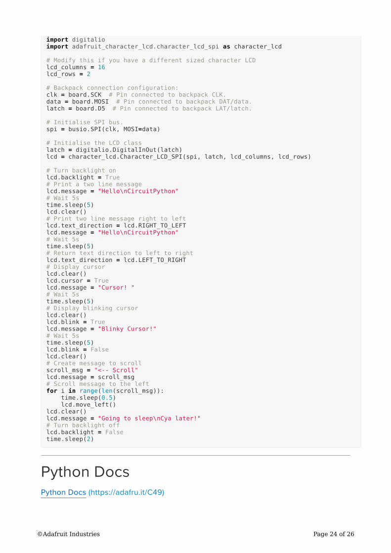
And a complete example of SPI usage is in the charlcd_SPI_simpletest.py (https://
adafru.it/CbU) example in the library. Save this as code.py on your board and it will
run a small demo of LCD functions.
# SPDX-FileCopyrightText: 2021 ladyada for Adafruit Industries
# SPDX-License-Identifier: MIT
"""Simple test for 16x2 character LCD connected to 74HC595 SPI LCD backpack."""
import time
import board
import busio
©Adafruit Industries Page 23 of 26
import digitalio
import adafruit_character_lcd.character_lcd_spi as character_lcd
# Modify this if you have a different sized character LCD
lcd_columns = 16
lcd_rows = 2
# Backpack connection configuration:
clk = board.SCK # Pin connected to backpack CLK.
data = board.MOSI # Pin connected to backpack DAT/data.
latch = board.D5 # Pin connected to backpack LAT/latch.
# Initialise SPI bus.
spi = busio.SPI(clk, MOSI=data)
# Initialise the LCD class
latch = digitalio.DigitalInOut(latch)
lcd = character_lcd.Character_LCD_SPI(spi, latch, lcd_columns, lcd_rows)
# Turn backlight on
lcd.backlight = True
# Print a two line message
lcd.message = "Hello\nCircuitPython"
# Wait 5s
time.sleep(5)
lcd.clear()
# Print two line message right to left
lcd.text_direction = lcd.RIGHT_TO_LEFT
lcd.message = "Hello\nCircuitPython"
# Wait 5s
time.sleep(5)
# Return text direction to left to right
lcd.text_direction = lcd.LEFT_TO_RIGHT
# Display cursor
lcd.clear()
lcd.cursor = True
lcd.message = "Cursor! "
# Wait 5s
time.sleep(5)
# Display blinking cursor
lcd.clear()
lcd.blink = True
lcd.message = "Blinky Cursor!"
# Wait 5s
time.sleep(5)
lcd.blink = False
lcd.clear()
# Create message to scroll
scroll_msg = "<-- Scroll"
lcd.message = scroll_msg
# Scroll message to the left
for i in range(len(scroll_msg)):
time.sleep(0.5)
lcd.move_left()
lcd.clear()
lcd.message = "Going to sleep\nCya later!"
# Turn backlight off
lcd.backlight = False
time.sleep(2)
Python Docs
Python Docs (https://adafru.it/C49)
©Adafruit Industries Page 24 of 26
Downloads
Hardware files
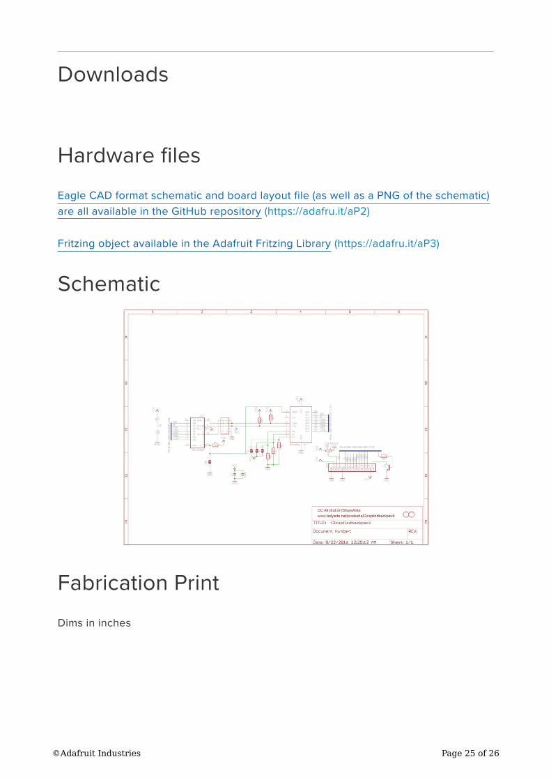
Eagle CAD format schematic and board layout file (as well as a PNG of the schematic)
are all available in the GitHub repository (https://adafru.it/aP2)
Fritzing object available in the Adafruit Fritzing Library (https://adafru.it/aP3)
Schematic
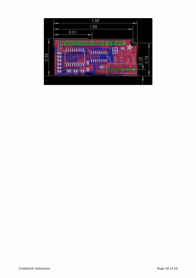
Fabrication Print
Dims in inches
©Adafruit Industries Page 25 of 26
©Adafruit Industries Page 26 of 26