i4000 series scanners - b&h photo video · safety user precautions • place the scanner on a...
TRANSCRIPT

User’s Guide
Eastman Kodak Company343 State StreetRochester, NY 14650 U.S.A.© Kodak, 2010. All rights reserved. TM: Kodak
6J7319A
CYAN MAGENTA YELLOW BLACKCYAN
8.5 x 11” Folded
GUIDE COVER-KODAK SCANNERS
FONTS
Whitney K Family
SIZE P/N SWATCHES
FILE FORMAT
DESIGN/IMPLEMENTATION
DATE02.09.10
6J7319A
DE MEYER
4 COLOR PROCESS
ARTWORK NAME
PRINTING INFORMATION
0000-000ECO LANGUAGES
ILLUSTRATOR CS3
EN
i4000 Series Scanners
A-616516J7319
User’s Guide on Installation CDGuides de l'utilisateur sur le CD d'installation
Benutzerhandbücher auf der Installations-CDGuida dell’utente sul CD di installazione
Guías de usuario incluidas en el CD de instalaciónGuias do usuário no CD de instalação
Gebruikershandleidingen op installatie-cdKurulum CD'sindeki Kullanım Kılavuzları
Uživatelská pøíruèka na instalaèním disku CD

Safety
User Precautions• Place the scanner on a sturdy, level work surface capable of supporting 38.8 kg (85.5 lbs) and leave adequate clearance on
all sides of the scanner.
• When relocating the scanner, it is recommended that two people lift the scanner and use safe lifting techniques.
• Do not install the scanner in a location subject to dust, humidity or steam. This may cause electrical shock or a fire. Only use the scanner indoors in a dry location.
• Make sure the electrical power outlet is located within 1.52 meters (5 feet) of the scanner and is easily accessible.
• When disconnecting equipment from the electric socket, be sure to grasp the plug, not the cord.
• Be sure the power cord is securely plugged into the wall outlet. Failure to do so may cause electrical shock or fire.
• Do not damage, knot, cut or modify the power cord or use a damaged power cord. This may cause electrical shock or fire.
• The scanner requires a dedicated and properly grounded power outlet. Do not use an extension cord or power strip with the scanner.
• Leave sufficient space around the power outlet so it can be easily unplugged in case of an emergency.
• Do not use the scanner if it becomes inordinately hot, has a strange odor, emits smoke, or makes unfamiliar noises. Immediately stop the scanner and disconnect the power cord from the power outlet. Contact Kodak Service.
• Do not disassemble, service or modify the scanner except as explained in the User’s Guide.
• Do not move the scanner with the power cord and interface cable attached. This may cause damage to the cord/cable. Remove the power cord from the wall outlet before moving or relocating the scanner.
• Follow the Kodak recommended cleaning procedures. Do not use air, liquid or gas spray cleaners. These cleaners displace dust, dirt and debris to other locations within the scanner, which may cause the scanner to malfunction.
• Material Safety Data Sheets (MSDS) for chemical products are available on the Kodak website at: www.kodak.com/go/msds. When accessing the MSDSs from the website, you will be required to provide the catalog number of the consumable you want the Material Safety Data Sheet for. See the section entitled, “Supplies and consumables” later in this guide for supplies and catalog numbers.
Users and their employers need to observe the common sense precautions applicable to the operation of any machinery. These include, but are not limited to, the following:
• Do not wear loose clothing, unbuttoned sleeves, etc.
• Do not wear loose jewelry, bracelets, bulky rings, long necklaces, etc.
• Hair length should be kept short, using a hair net if needed, or tying long hair up in a bundle.
• Remove all other loose objects from the area that could be drawn into the machine.
• Take sufficient breaks to maintain mental alertness.
• Use only the recommended cleaning supplies.
• Do not use canned/compressed air.
Supervisors should review their employee practices and make compliance with these precautions a part of the job description for operation of the scanner or any mechanical device.
Warning labelsCAUTION: Moving parts, avoid contact.
CAUTION: Hot surface, avoid contact.
Environmental information• The Kodak i4000 Series Scanners are designed to meet worldwide environmental requirements.
• Guidelines are available for the disposal of consumable items that are replaced during maintenance or service; follow local regulations or contact Kodak locally for more information.
• The product packaging is recyclable.
• Kodak i4000 Series Scanners are Energy Star compliant and shipped from the factory with the default time set to 15 minutes.
European UnionThis symbol indicates that when the last user wishes to discard this product, it must be sent to appropriate facilities for recovery and recycling. Please contact your local Kodak representative or refer to www.kodak.com/go/recycle for additional information on the collection and recovery programs available for this product.
Please consult www.kodak.com/go/REACH for information about the presence of substances included on the candidate list according to article 59(1) of Regulation (EC) No. 1907/2006 (REACH).
Acoustic emissionMaschinenlärminformationsverordnung – 3, GSGVDer arbeitsplatzbezogene Emissionswert beträgt <70 dB(A).
[Machine Noise Information Ordinance — 3, GSGVThe operator-position noise emission value is <70 dB(A).]
EMC statementsUnited States: This equipment has been tested and found to comply with the limits for a Class B digital device pursuant to Part 15 of the FCC rules. These limits are designed to provide reasonable protection against harmful interference in a residential installation. This equipment generates, uses, and can radiate radio frequency energy and, if not installed and used in accordance with the instruction manual, may cause harmful interference to radio communications. However, there is no guarantee that interference will not occur in a particular installation. If this equipment does cause harmful interference to radio or television reception, which can be determined by turning the equipment off and on, the user is encouraged to try to correct the interference by one or more of the following measures:
• Reorient or relocate the receiving antenna.
• Increase the separation between the equipment and receiver.
• Connect the equipment into an outlet on a circuit different from that to which the receiver is connected.
• Consult the dealer or an experienced radio/TV technician for additional suggestions.
Any changes or modifications not expressly approved by the party responsible for compliance could void the user’s authority to operate the equipment. Where shielded interface cables have been provided with the product or specified additional components or accessories elsewhere defined to be used with the installation of the product, they must be used in order to ensure compliance with FCC regulation.
Korea: As this equipment has obtained EMC registration for household use, it can be used in an area including residential areas.
Japan: This is a Class B product based on the standard of the Voluntary Control Council for interference by information Technology Equipment (VCCI). If this is used near a radio or television receiver in a domestic environment, it may cause radio interference. Install and use the equipment according to the instruction manual.

OVERVIEW 1-1
INSTALLATION 2-1
SCANNING 3-1
DOCUMENT PRINTING 4-1
MAINTENANCE 5-1
TROUBLESHOOTING 6-1
APPENDICIES

A-61651 December 2009 1-1
1 Overview
Contents Supporting documentation .........................................................................1-1Accessories................................................................................................1-2What’s in the box........................................................................................1-2Scanner components .................................................................................1-3
The Kodak i4000 Series Scanners include the following models:
Kodak i4200 Scanner — desktop duplex color scanner that scans up to 100 pages per minute (200 dpi, black and white, landscape orientation) lettersize documents.
Kodak i4600 Scanner — desktop duplex color scanner than scans up to 120 pages per minute (200 dpi, black and white, landscape orientation) lettersize documents.
This User’s Guide provides information and procedures for using and maintaining the Kodak i4000 Series Scanner. The information in this guide is for use with both models unless otherwise noted.
Supporting documentation
In addition to this User’s Guide, the following documentation is also available:
• Installation Guide — provides a step-by-step procedure for installing the scanner.
• Scanner Setup Guides — the TWAIN Datasource and ISIS Driver are included with the Kodak i4000 Series Scanner. Each Scanner Setup Guide explains how to use basic image processing features and both guides are provided on the Installation CD in PDF format. You can also download these guides from the website.
• Smart Touch User’s Guide — provides information and procedures on how to use Smart Touch functionality. This guide is provided on the Installation CD in PDF format. You can also download these guides from the website.
• Reference Guide — provides easy visual steps for cleaning your scanner. Keep this guide close to the scanner so you can use it as an easy reference.
Website: www.kodak.com/go/docimaging

1-2 A-61651 December 2009
Accessories Kodak Enhanced Printer Accessory — the Kodak Enhanced Printer Accessory provides an effective way to apply information to the scanned document. It operates at full scanner speed. The printer can add a date, time, document sequential counter and custom messages. All printer controls and functions are accessible through the TWAIN Datasource or ISIS Driver.
Document Extenders — document extenders are available for scanning documents longer than 43.2 cm (17 inches). These extenders are available in 66.04 cm, 76.2 cm and 86.36 cm (26- 30- and 34-inch) lengths.
Kodak Feeder Kit for Ultra-Lightweight Paper — allows you to feed lightweight paper from a paper weight range of 25 g/m2 to 75 g/m2 kg(7 to 20 lbs). The Kodak Feeder Kit for Ultra-Lightweight Paper includes a feed module and separation roller that are specially designed to feed light-weight paper through the scanner transport.
What’s in the box Before you begin open the box and check the contents:
• Kodak i4200 or i4600 Scanner• Output tray• USB 2.0 cable• AC power cord bundles• Welcome Folio which includes:
- Installation CD - Application CDs - Warranty/Registration sheets- Printed User’s Guide, English- Printed Reference Guide (multi-languages)- Printed Installation Guide- Sample Cleaning Kit- Service & Support Contact Information sheets- Miscellaneous flyers

A-61651 December 2009 1-3
Scanner componentsFront view
1 Printer access cover — lift this cover to access the feed module release knob and the optional Enhanced Printer for changing printer positions and maintenance. The scanner serial number and K number are also located in this area.
2 Scanner cover — provides access to the internal components.
3 Output tray — collects the scanned documents.
4 Output tray side guides — can be moved in and out to accommodate document size or folded flat on the output tray.
5 Document stop — aids in document stacking. You can slide this stop in or out to accommodate the size of documents you are scanning or it can be folded flat on the output tray.
6 Output tray height adjustment tab — this tab should be pulled out to raise the front of the output tray when scanning for improved document scanning. When the output tray is lifted, this tab automatically releases and rests on the print access cover.
7 Function window — displays 0 - 9. These numbers correspond to a predefined function. Other display patterns are also used to indicate scanner status or operator action. See Chapter 6 for more information.
8 Scanner cover release latch — pull the lever forward to open the scanner cover.
9 Scroll button — allows you to select or scroll through predefined functions or applications for scanning.
10 Start/Resume button — press to start or resume scanning. Also includes a green LED indicating scanner status (i.e., power is on and ready to scan).
10
9
8
7
6
54
3
2
1

1-4 A-61651 December 2009
11 Stop/Pause button — press once to temporarily pause scanning (the Start/Resume button can then be used to resume scanning). Press twice to stop scanning. The red LED on this button indicates a possible error condition has been detected (i.e., document jam).
12 Power button — press to turn the scanner on or press and hold for one second to turn the scanner off.
13 Input Elevator side guides — slide the guides in or out to accommodate the document size you want to scan. Side guides can be left-, center- and right-adjusted to accommodate documents of various widths. The side guides can also be locked into position if desired.
14 Input Elevator— holds up to 500 documents (20 lb/75 g/m2) in place. The input elevator can be set to accommodate stacks of 25-, 100-, 250- or 500-documents. The input elevator can be folded up when it is not in use.
15 Input Elevator extender — pull this extender out to accommodate documents longer than 35.6 cm (14 inches).
16 Print location indicators — there are detents at the edge of the input elevator to indicate where the print positioning will be on the paper.
17 Gap release toggle switch — push in to adjust the space between the feed module and separation module for documents that require special handling.
1615 14 13
11
12
17

A-61651 December 2009 1-5
Printer access view Even if you do not have the Kodak Enhanced Printer Accessory, you will still need to access this area of the scanner. The feed module release knob is located in this area.
1 Printer cable — this cable connects directly to the printer carrier to allow communication to the Enhanced Printer.
2 Enhanced Printer carrier/cartridge — allows front printing on documents. This is only present if the Enhanced Printer Accessory is installed.
3 Print positions — 8 print positions are available.
4 Feed module release knob — turn this knob to release the feed module from it’s position for cleaning or replacing. The arrow on the release knob should be pointing to the left when the feed module is engaged; and right when the feed module is disengaged.
1
2
3
4

1-6 A-61651 December 2009
Inside view When you pull the scanner cover release latch forward the following internal components are visible.
1 Separation module — provides smooth document feeding and separation of various sizes, thicknesses and textures of documents.
2 Imaging guides — keep imaging guides clean to obtain optimum image quality.
3 Black/White background — using the application software this background can be changed to White or Black. Under normal scanning conditions, you would use the black background. If you are scanning lightweight or thin paper with printing on one side, you can use the white background to help eliminate bleed-through in the final image. See the User’s Guide for Image Processing - TWAIN Datasource/ISIS Driver for more information.
4 Rollers — provides smooth transport of documents through the scanner.
5 Feed module — provides smooth document feeding and separation of various sizes, thicknesses and textures of documents.
6 Ink blotter channels and ink blotters — the ink blotters which are placed in these channels, collect ink residue from the optional Enhanced Printer Accessory.
7 Sensors — these three ultrasonic sensors cover the width of the paper path which aid in detecting multifed documents.
8 Paper present sensor — detects the presence of documents in the input elevator. Documents must be covering this sensor in order for the scanner to begin scanning.
1
2
2
3
3
4
5
6
7
8

A-61651 December 2009 1-7
Rear view
1 Rear document exit — allows you to exit exception documents from the rear of the scanner.
2 Rear document exit toggle — toggle this switch to enable the straight-through paper path option of the scanner allowing exception documents to be outputted through the rear document exit.
3 USB ports — connects the scanner to the PC and allows the connection of other peripheral devices.
4 Power port — connects the power cord to the scanner.
5 Security lock port — connects a security lock to the scanner. You can purchase a standard security lock at an office supply store. Refer to the instructions provided with the security lock for installation procedures.
4
3
2
1 5

A-61651 December 2009 2-1
2 Installation
Contents Installing the scanner .................................................................................2-1Installing the Kodak Driver Software .....................................................2-2Attaching the output tray........................................................................2-3Connecting the power cord and USB cable...........................................2-3
Turning on the scanner ..............................................................................2-4Turning off the scanner ..............................................................................2-4
Installing the scanner This section provides detailed information supporting the Installation Guide that is provided with your scanner. Follow these steps in the order they are provided to install your scanner.
NOTES:
• If you have already performed all of the steps in the Installation Guide, skip this section.
• When positioning the scanner, be sure to provide adequate clearance at the back of the scanner if you will be using the rear document exit. For more information on the rear document exit, see the section entitled, “Adjusting the output tray” in Chapter 3.

2-2 A-61651 December 2009
Installing the Kodak Driver Software - Windows operating systems
Do not install the USB cable before installing the Kodak Driver Software.1. Insert the Kodak i4000 Series Scanners Installation CD in the CD-ROM
drive. The installation program starts automatically.
2. Select Install Scanner Software.
NOTES:
• If the CD does not start automatically, open the My Computer icon on your desktop. Double-click the icon indicating your CD-ROM drive, then double-click on setup.exe.
• If the message Portions of this application are already installed is displayed, click Yes to continue the installation process. Any previously installed Kodak Scanner software that is shared with this scanner will be updated.
3. Click Next when the Welcome screen is displayed.
4. Click I Agree after you have read and agreed with the terms of the Software License Agreement. The installation will start and several progress screens will be displayed.
5. Click Finish when the installation is complete.
6. Remove the Installation CD from the CD-ROM drive.

A-61651 December 2009 2-3
Attaching the output tray When you unpack the Kodak i4000 Series Scanner, the output tray is packed in a separate box.
• Locate the output tray slots on the scanner, align the output tray with the slots and set the output tray in place.
Connecting the power cord and USB cable
When the drivers have been installed, connect the power cord and USB cable to the scanner. Refer to the illustration below for making proper connections. Make sure the power outlet is located within 1.52 meters (5 feet) of the scanner and is easily accessible.
1. Select the appropriate AC power cord for your region from the supply of power cords packed with your scanner.
2. Plug the output power cord into the power port on the scanner. Be sure it is securely attached.
3. Plug the other end of the power cord into the wall outlet.
4. Attach the USB cable to the scanner USB port.
5. Attach the other end of the USB cable to the proper USB port on your PC.

2-4 A-61651 December 2009
6. Secure the power cord and USB cable into the cable routing channel on the back of the scanner.
Turning on the scanner
• Press the Power button.
When you turn on the scanner, the input elevator will open if it is not already opened and the green indicator on the Start/Resume button will flash as the scanner goes through a series of self tests.
The scanner takes less than 15 seconds to complete the power-up sequence and be ready to scan.
When the installation process is complete and ready to scan, the green LED on the Start/Resume button will stop flashing and remain constant and the number 1 will be displayed in the function window. If any other number is displayed, see the section entitled, “LED error codes” in Chapter 6 for an explanation of these codes.
Turning the scanner off
• Press the Power button for one second.

A-61651 December 2009 3-1
3 Scanning
Contents Quick start ..................................................................................................3-1Getting your scanner ready to scan ...........................................................3-1
Adjusting the input elevator ....................................................................3-2Installing the document extender ...........................................................3-4Adjusting the output tray ........................................................................3-4
Getting your documents ready to scan ......................................................3-6Selecting your scanning application ..........................................................3-7
Quick start Kodak i4000 Series Scanners were designed to be easy to use and get you scanning quickly. All you need to do to start scanning to PDF is place your documents in the input elevator, press the Scroll button to display “2” and press the Start/Resume button. It’s that easy!
To learn more about all the features of your Kodak i4000 Series Scanner, read the rest of this chapter.
Getting your scanner ready to scan
1. Be sure the scanner is on and ready to scan (Start/Resume button LED is green and constant).
NOTE: If any function codes (i.e., U1, U2, etc.) are displayed, they can be cleared by pressing the Stop/Pause button.
2. Adjust the input elevator to meet your scanning needs. See the section entitled, “Adjusting the input elevator” for more information.
3. Adjust the output tray to meet your scanning needs. See the section entitled, “Adjusting the output tray” for more information.
4. Select your scanning application. The scanner comes with Smart Touch functionality and Kodak Capture Desktop Software.

3-2 A-61651 December 2009
Adjusting the input elevator
You can adjust the side guides and input elevator height to accommodate your scanning needs. When the scanner is not is use, the input elevator can be folded up against the scanner.
NOTE: The input elevator must be in the lowest position before closing it.
• Adjusting the side guides — the side guides can be adjusted for right-edge, left-edge or center feeding. The side guides can be moved together for center feeding or independently for offset feeding (right-edge or left-edge). Before moving the side guides, be sure the locking switch is not in the locked position (see below).
NOTE: When using the optional Enhanced Printer, documents should be placed in the input elevator in a manner that will align the print string in the proper location. Offset feeding may be required.
• Locking the side guides — side guides may be locked into position after they are adjusted. This may be helpful when the placement of a print string is important.
To lock the side guides remove any documents from the input elevator and move the lock switch to the left (the locked position).
A-61651 December 2009 3-3
• Adjusting the height of the input elevator — the input elevator can be set to accommodate stacks of 25-, 100-, 250- or 500-documents of 20 lb./75 g/m2 bond paper. Input elevator settings are made through your scanning application software (i.e., TWAIN Datasource or ISIS Driver).
When the input elevator is set to 25, the input elevator will remain in the up position. When set to 100, 250 or 500, the input elevator will automatically raise to feed documents and lower after the last document in your stack has been fed.
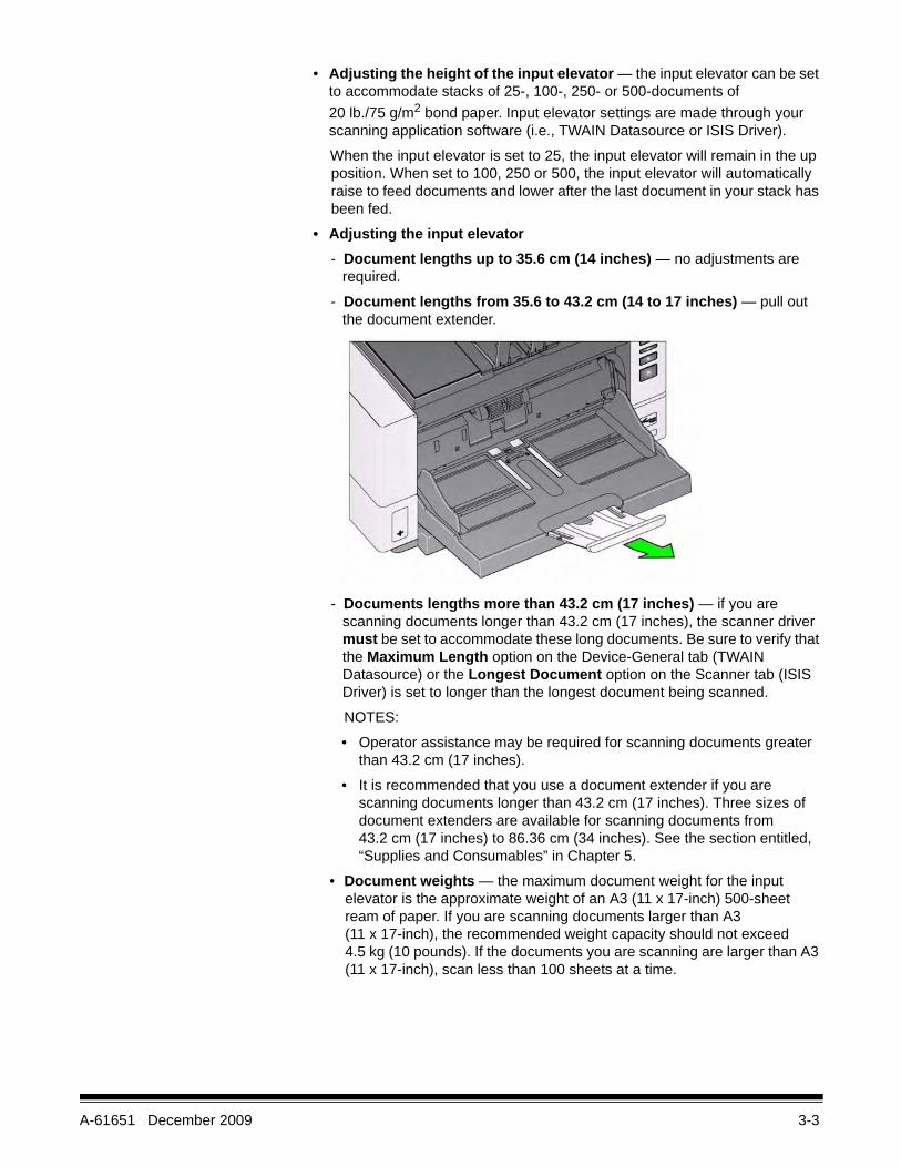
• Adjusting the input elevator- Document lengths up to 35.6 cm (14 inches) — no adjustments are
required.
- Document lengths from 35.6 to 43.2 cm (14 to 17 inches) — pull out the document extender.
- Documents lengths more than 43.2 cm (17 inches) — if you are scanning documents longer than 43.2 cm (17 inches), the scanner driver must be set to accommodate these long documents. Be sure to verify that the Maximum Length option on the Device-General tab (TWAIN Datasource) or the Longest Document option on the Scanner tab (ISIS Driver) is set to longer than the longest document being scanned.
NOTES:
• Operator assistance may be required for scanning documents greater than 43.2 cm (17 inches).
• It is recommended that you use a document extender if you are scanning documents longer than 43.2 cm (17 inches). Three sizes of document extenders are available for scanning documents from 43.2 cm (17 inches) to 86.36 cm (34 inches). See the section entitled, “Supplies and Consumables” in Chapter 5.
• Document weights — the maximum document weight for the input elevator is the approximate weight of an A3 (11 x 17-inch) 500-sheet ream of paper. If you are scanning documents larger than A3 (11 x 17-inch), the recommended weight capacity should not exceed 4.5 kg (10 pounds). If the documents you are scanning are larger than A3 (11 x 17-inch), scan less than 100 sheets at a time.

3-4 A-61651 December 2009
Installing the document extender
• Insert the ends of the document extender into the holes on the input elevator or the output tray and lower the extender into position.
Adjusting the output tray The Kodak i4000 Series Scanners are designed with improved stacking performance which allows most users to scan documents without the assistance of the output tray side guides and document stop. With one or both side guides down and the height adjustment tab raised, you can quickly and easily remove the scanned documents from the front-, right- or left-side of the scanner. Try using this method before using the side guides and document stop.
NOTE: If you find it more convenient to use the side guides and document stop, see the next section for adjustment procedures.
• Adjusting the angle of the output tray — it is strongly recommended that you scan documents with the angle of the output tray in the “up” position to achieve best stacking performance. Just lift the front of the output tray and the height adjustment tab will release from underneath the output tray.
To lower the output tray, gently push the height adjustment tab underneath the output tray while lowering the output tray on the printer access cover.

A-61651 December 2009 3-5
• Adjusting the side guides — open and adjust the side guides on the output tray to match the position of the side guides on the input elevator. The side guides can also be folded flat against the output tray.
• Adjusting the document stop — adjust the output tray document stop to slightly longer than the longest document being fed. If you are scanning documents longer than the output tray will accommodate, fold the document stop flat on the output tray.
• Opening the rear document exit — documents that require special handling (i.e., fragile documents, shipping envelopes, etc.) can be outputted using the rear document exit. This exit provides the straight-through paper path option that allows an exception document(s) to pass through the transport, thus reducing the possibility of a document jam.

3-6 A-61651 December 2009
Use the rear document exit when:
• documents are too stiff (e.g., rigid) to make the turn in the transport and are jamming (U9 is being displayed in the function window).
• documents are fragile and you do not want to bend them.
• output stacking order is not important.
• scanning directly into the recycle bin when documents are no longer needed after scanning.
• scanning photographs.
NOTES:
• Be sure to toggle the rear document exit switch back into it’s original position when finished.
• Be sure that you have adequate clearance behind the scanner to feed the document(s) through when using this option.
• When scanning several documents through the rear document exit, the documents will be outputted in the reverse scanning order.
Getting your documents ready to scan
1. Standard paper size documents feed easily through the scanner. When organizing your documents for scanning, stack the documents so the lead edges are aligned and centered in the input elevator. This allows the feeder to introduce documents into the scanner one at a time.
2. Remove all staples and paper clips before scanning. Staples and paper clips on documents may damage the scanner and documents.
3. All inks and correction fluids on the paper must be dry before scanning is started.
4. Torn, damaged or crushed pages can be transported successfully through the scanner. However, no scanner can transport every possible type of damaged paper. If in doubt about whether a specific damaged document can be transported through the scanner, place the document in a clear protective sleeve and use the rear document exit. Sleeves should be manually fed, one at a time, folded edge first, using the gap release toggle switch.
5. Place the documents you want to scan in the input elevator. If you are scanning one-sided documents, be sure the side you want to scan is facing the input elevator.
NOTES:
• Some very thick and/or stiff documents; such as shipping envelopes, may require the following:
- Use of the rear document exit.
- Use of the gap release toggle switch.
- Removal of the pre-separation pad.
- Scanning at 300 dpi or more to reduce the scanner transport speed.

A-61651 December 2009 3-7
Selecting your scanning application
Kodak has included two scanning applications with your scanner:• Smart Touch — Kodak provides Smart Touch functionality which allows you
to quickly and easily perform common scanning tasks; such as:
- scan and share incoming client correspondence with a co-worker in a branch office
- create a searchable PDF of a printed report
- scan text to be included in documentation
Nine predefined task shortcuts are available for your use. You can modify and rename any of the shortcuts to create your own custom tasks. You can also preview and easily edit images (zoom, pan, rotate, crop, etc.) before they are sent to their destination.
For more information about Smart Touch, see the User’s Guide for Smart Touch on the Installation CD.
• Kodak Capture Desktop Software — an intuitive and easy-to-use capture software application, specifically designed to make processing and sharing scanned documents easy. With Kodak Capture Desktop Software you’ll receive “out of the box” production and be able to immediately capture, edit and output anything from single documents to larger batches in distributed or departmental environments.
Along with the essentials for easy and productive scanning, Kodak Capture Desktop Software shares the design and interface of Kodak Capture Pro Software, which offers many more advanced capabilities for image and data capture automation.
Through a complete set of icon-based tools and other features, Kodak Capture Desktop Software offers simplified scanning. Quickly and easily scan to file, create searchable PDFs or integrate your information into a common location - such as Microsoft SharePoint.
Kodak Capture Pro Software is also available for use with the Kodak i4000 Series Scanners. Go to www.Kodak.com/go/capturepro for more information.
Many other companies have included support for Kodak i4000 Series Scanners in their scanning applications. Contact these companies for assistance in using these applications.
A-61651 December 2009 4-1
4 Document Printing
Contents Printer specifications..................................................................................4-2Installing/Replacing the ink cartridge .........................................................4-3Running a print test ....................................................................................4-5Changing print positions ............................................................................4-8Installing/Replacing the ink blotter strips....................................................4-9Problem solving .......................................................................................4-10
This chapter provides information for using the optional Kodak Enhanced Printer. In order to use the printing option you must have purchased and installed the Enhanced Printer Accessory.
NOTE: See the instructions that came with the Enhanced Printer Accessory for procedures on how to install this accessory.
Refer to the Scanning Setup Guide for the TWAIN Datasource or ISIS Driver on the CD or your scanning application documentation for more information about enabling printing and setting up print strings.
The Enhanced Printer operates at full scanner speed. The printer can add a date, time, document sequential counter and custom messages.
The print string can be configured to include information that stays the same for each document; such as batch name or operator and information that may change for each page scanned; i.e., the document sequential counter.
All printer controls and functions are accessible through the TWAIN Datasource or ISIS Driver.
NOTES:
• Printing must be enabled and an ink cartridge must be installed before starting a scan session.
• Clean the scanner’s paper path components daily when using the printer.• You cannot print on documents that are smaller than 10 cm (4 in.) in length.• If you attempt to scan with a job setup that has Printing enabled, and you do
not have an Enhanced Printer installed, a U2 error will be displayed.

4-2 A-61651 December 2009
Printer specifications More information about the following specifications can be found in the TWAIN Datasource or ISIS Driver Scanning Setup Guide.
Characteristic DescriptionMaximum lines 1 Maximum characters 40 (including spaces)Print locations (horizontal) 8 front manually setPrint locations (vertical) Set by the scanning applicationPrint orientation 0 and 90 degreesFont size Normal, Bold and Extra Bold
NOTE: Not all languages can support a Bold font based on the complexity of the characters, such as half-width Katakana.
Print side Front (pre-scan) Minimum printing distance from document lead edge
0.89 cm (0.35 in.)
Ink cartridge Black: HP-C6602ARed: HP-C6602R
Characters per ink cartridge Up to 1,500,000 to 2,000,000 (based on font size used)
Static fields available User-specified messages via capture software application
Dynamic fields available Up to a nine-digit sequential document number, date, four-digit time
Languages supported Any phonetic language. For example: Dutch, English, French, German, Italian, Portuguese, Spanish, Japanese (half-width Katakana)

A-61651 December 2009 4-3
Installing/Replacing the ink cartridge
You must install the ink cartridge before using the printer. Refer to the section entitled, “Supplies and consumables” in Chapter 5 for ordering information.
After initial installation, replace the ink cartridge when:
• printed characters appear light or uneven• missing characters are evident• a print test reveals inconsistent character quality• cleaning has not improved the overall print quality
IMPORTANT: Dispose the empty ink cartridge in accordance with all federal, state and local laws.
1. Remove the output tray.
2. Open the printer access cover.
NOTE: If you do not want to remove the output tray, you can lift the front of the output tray, then lift the printer access cover and position the printer access cover behind the height adjustment tab.

4-4 A-61651 December 2009
3. If you are installing the ink cartridge for the first time, push the connector on the printer cable firmly into the printer carrier.
NOTE: If you are replacing an ink cartridge, the printer cable will already be installed and you just need to remove the printer carrier from it’s position and remove the empty ink cartridge.
4. Open the ink cartridge package and remove the tab from the new ink cartridge.
5. Lift the green tab on the printer carrier and slide the new ink cartridge in the printer carrier and close the tab.
NOTES:
• If the printer cable should become disconnected, snap it back into position.
• Ink cartridge disposal: consult the Hewlett-Packard website for recycling printing supplies or disposing of the ink cartridges according to local regulations.
A-61651 December 2009 4-5
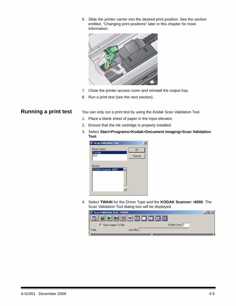
6. Slide the printer carrier into the desired print position. See the section entitled, “Changing print positions” later in this chapter for more information.
7. Close the printer access cover and reinstall the output tray.
8. Run a print test (see the next section).
Running a print test You can only run a print test by using the Kodak Scan Validation Tool.
1. Place a blank sheet of paper in the input elevator.
2. Ensure that the ink cartridge is properly installed.
3. Select Start>Programs>Kodak>Document Imaging>Scan Validation Tool.
4. Select TWAIN for the Driver Type and the KODAK Scanner: i4000. The Scan Validation Tool dialog box will be displayed.

4-6 A-61651 December 2009
5. Click the Setup icon. The Scan Validation Tool main window will be displayed.
6. Select the Default Setting Shortcut and click Settings.
7. On the General tab, click the Device button.

A-61651 December 2009 4-7
8. On the Device - General tab, click the Diagnostics button. The General-Diagnostics window will be displayed.
9. Check the Printer check box and click Done.
10. Scan the blank sheet of paper that is in the input elevator.
11. Check the quality of the test pattern. If the test pattern is inconsistent, you may need to clean the print head or change the ink cartridge.
NOTE: Clean the print head by removing it from the printer carrier and dabbing the print head with a damp cloth.
Acceptable Unacceptable: pattern is inconsistent

4-8 A-61651 December 2009
Changing print positions
The horizontal print position must be changed manually.
1. Remove the output tray.
2. Open the printer access cover.
NOTES:• The horizontal print positions are visible by a small detent on the printer
rail.
• Printing automatically stops approximately 1.27 cm (½-inch) from the trailing edge of the document, even if the information has not been completely printed.
3. Lift up on the printer carrier and remove it from it’s position.
4. Align the slot on the printer carrier with the desired horizontal print position and slide the printer carrier in place.
NOTE: The print location indicators at the edge of the input elevator can be used as a guide to verify your horizontal print position.
5. Close the printer access cover and reinstall the output tray.
Indicators

A-61651 December 2009 4-9
Installing/Replacing the ink blotter strips
The two ink blotter strips, which will be placed in the ink blotter channels at installation, are located in the scanner transport to collect ink overflow. To order additional ink blotter strips, see the section entitled, “Supplies and Consumables” in Chapter 5.
1. Pull the scanner cover release latch forward to release and lift the scanner cover.
2. Locate the two blotter strip channels. These channels are where the blotter strips will be installed or replaced.
3. If you are replacing a blotter strip, proceed with Step 4, if not, go to Step 5.
4. Grasp the blotter strip, carefully pull it off of the channel and discard the soiled strip according to local regulations.
5. Remove the backing from a new blotter strip.
6. Align the blotter strip in one of the channels.
NOTE: Improperly aligned blotter strips may cause document jams.
7. Press the adhesive side of the blotter strip down firmly into the channel.
8. Repeat Steps 4-7 for the other strip.
9. Close the scanner cover.
4-10 A-61651 December 2009
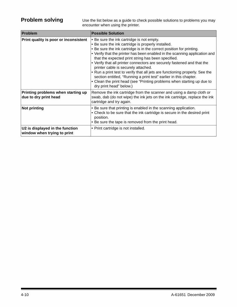
Problem solving Use the list below as a guide to check possible solutions to problems you may encounter when using the printer.
Problem Possible SolutionPrint quality is poor or inconsistent • Be sure the ink cartridge is not empty.
• Be sure the ink cartridge is properly installed.• Be sure the ink cartridge is in the correct position for printing.• Verify that the printer has been enabled in the scanning application and
that the expected print string has been specified.• Verify that all printer connectors are securely fastened and that the
printer cable is securely attached.• Run a print test to verify that all jets are functioning properly. See the
section entitled, “Running a print test” earlier in this chapter.• Clean the print head (see “Printing problems when starting up due to
dry print head” below.)Printing problems when starting up due to dry print head
Remove the ink cartridge from the scanner and using a damp cloth or swab, dab (do not wipe) the ink jets on the ink cartridge, replace the ink cartridge and try again.
Not printing • Be sure that printing is enabled in the scanning application.• Check to be sure that the ink cartridge is secure in the desired print
position.• Be sure the tape is removed from the print head.
U2 is displayed in the function window when trying to print
• Print cartridge is not installed.

A-61651 December 2009 5-1
5 Maintenance
Contents Cleaning frequency chart ...........................................................................5-2Cleaning tools and materials......................................................................5-2Opening the scanner cover ........................................................................5-2Cleaning procedures..................................................................................5-3
Vacuuming the output tray and input elevator.......................................5-4Cleaning the rollers ...............................................................................5-4Cleaning the separation roller tires .......................................................5-5Cleaning the feed module tires .............................................................5-6Cleaning the Flippable White Background strip(s) ................................5-6Cleaning the imaging guides - basic cleaning.......................................5-7Cleaning the imaging guides - thorough cleaning.................................5-8Running a transport cleaning sheet ....................................................5-10Final cleaning steps ............................................................................5-10
Replacement procedures ........................................................................ 5-11Replacing the feed module or feed module tires ................................. 5-11Replacing the separation roller or separation roller tires.....................5-14Replacing the pre-separation pad .......................................................5-15Replacing the imaging guides.............................................................5-16Replacing the Flippable White Background strip(s) ............................5-16
Supplies and consumables .....................................................................5-17
This chapter describes the required cleaning and maintenance procedures for the Kodak i4000 Series Scanners. The frequency of these procedures will vary with different scanning environments, paper types and image processing requirements. High volumes of scanning will demand more frequent cleaning of the scanner and more frequent replacement of consumables. Lower scanning volumes will allow longer times between these activities. Refer to the “Cleaning frequency chart” on the next page for cleaning guidelines. However, you will need to determine what works best for you. Years of Kodak’s production scanning experience proves that properly cleaning and maintaining your scanner will result in scanning more paper in less time with less issues. A properly maintained i4000 Series Scanner will provide years of trouble-free operation.
Scanner consumables (tires, pre-separation pads, etc.) and cleaning supplies are available from resellers, web merchants and from the Kodak on-line store (http:/scannerstore.kodak.com). Consumables are sold in kits of various sizes. The kits contain the proper mix of tires, rollers, and pre-separation pads so you can easily replace them at the recommended rate. For example, only replacing the tires and never replacing the separation roller will eventually minimize scanner performance. Replacing the consumables at the recommended frequency will ensure the best performance.
5-2 A-61651 December 2009
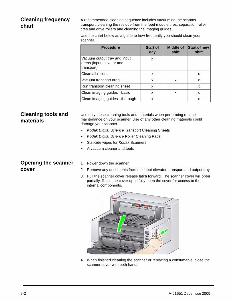
Cleaning frequency chart
A recommended cleaning sequence includes vacuuming the scanner transport, cleaning the residue from the feed module tires, separation roller tires and drive rollers and cleaning the imaging guides.
Use the chart below as a guide to how frequently you should clean your scanner.
Cleaning tools and materials
Use only these cleaning tools and materials when performing routine maintenance on your scanner. Use of any other cleaning materials could damage your scanner.
• Kodak Digital Science Transport Cleaning Sheets• Kodak Digital Science Roller Cleaning Pads• Staticide wipes for Kodak Scanners• A vacuum cleaner and tools
Opening the scanner cover
1. Power down the scanner.
2. Remove any documents from the input elevator, transport and output tray.
3. Pull the scanner cover release latch forward. The scanner cover will open partially. Raise the cover up to fully open the cover for access to the internal components.
4. When finished cleaning the scanner or replacing a consumable, close the scanner cover with both hands.
Procedure Start of day
Middle of shift
Start of new shift
Vacuum output tray and input areas (input elevator and transport)
x
Clean all rollers x xVacuum transport area x x xRun transport cleaning sheet x xClean imaging guides - basic x x xClean imaging guides - thorough x x

A-61651 December 2009 5-3
Cleaning procedures Cleaning your scanner and performing preventative maintenance on a regular basis is required to ensure the best possible image quality.
Some document types generate more paper dust and debris and may require more frequent cleaning.
Before cleaning your scanner or replacing consumables, review the following information:
• Some debris from the rubber tires on the feed module and separation roller is normal. Tire debris does not always mean that the tires are worn or damaged. After cleaning, inspect the tires for wear and replace the separation roller or feed module if necessary.
• When cleaning rollers/tires, allow the rollers/tires to dry completely before scanning.
• Use only the recommended cleaning supplies. Using unapproved cleaning fluids or solvents may damage the rubber tires.
• Do not use cleaners in confined areas, use with adequate ventilation.• Do not use cleaners on hot surfaces. Allow surfaces to cool to ambient
temperature before use.• Do not use canned/compressed air. Use of compressed air may cause
dust to be forced into the scanner’s imaging system and lodge in an area that causes image quality issues and cannot be cleaned without removing the camera.
• Do not use flammable compressed aerosols on or around the scanner.• In addition to the recommended cleaning supplies, you may use a vacuum
cleaner to remove debris from the scanner.• Staticide Wipes contain isopropanol which can cause eye irritation and dry
skin. Wash your hands with soap and water after performing maintenance procedures. Refer to the Material Data Safety Sheet (MSDS) for more information. The MSDS is available on the Kodak web site at www.kodak.com/go/MSDS.
NOTE: To access the MSDS, you will need to provide the catalog number of the supply. See “Supplies and Consumables” later in this chapter for catalog numbers.
• The roller cleaning pad contains sodium lauryl ether sulfate and sodium silicate which can cause eye irritation. Refer to the MSDS for more information.

5-4 A-61651 December 2009
Vacuuming the output tray and input elevator
1. Power down the scanner.
2. Remove the output tray.
3. Thoroughly vacuum the output tray area and the input elevator area.
Cleaning the rollers Cleaning the rollers includes all of the rollers in the transport area, the separation roller tires and the feed module tires.
1. Open the scanner cover.
2. Manually rotate and wipe the rollers with a roller cleaning pad.
3. Dry the rollers with a lint-free cloth.
A-61651 December 2009 5-5
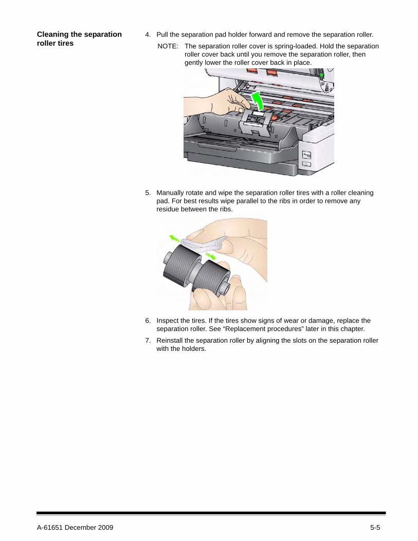
Cleaning the separation roller tires
4. Pull the separation pad holder forward and remove the separation roller.
NOTE: The separation roller cover is spring-loaded. Hold the separation roller cover back until you remove the separation roller, then gently lower the roller cover back in place.
5. Manually rotate and wipe the separation roller tires with a roller cleaning pad. For best results wipe parallel to the ribs in order to remove any residue between the ribs.
6. Inspect the tires. If the tires show signs of wear or damage, replace the separation roller. See “Replacement procedures” later in this chapter.
7. Reinstall the separation roller by aligning the slots on the separation roller with the holders.

5-6 A-61651 December 2009
Cleaning the feed module tires
8. Clean the feed module tires by manually rotating and wiping the feed module tires with a roller cleaning pad. For best results wipe parallel to the ribs in order to remove any residue between the ribs. You do not need to remove the feed module to clean the tires.
9. Inspect the tires. If the tires show signs of wear or damage, replace the feed module tires. See “Replacement procedures” later in this chapter.
Cleaning the Flippable White background strips
10. Wipe the upper and lower background strips with a Staticide wipe.
11. Wipe the upper and lower background strips again with an almost-dry Staticide wipe to remove any streaks.

A-61651 December 2009 5-7
Cleaning the imaging guides — basic cleaning
12. Wipe the upper and lower imaging guides with a Staticide wipe.
13. Wipe the upper and lower imaging guides again with an almost-dry Staticide wipe to remove any streaks.
14. Close the scanner cover.

5-8 A-61651 December 2009
Cleaning the imaging guides — thorough cleaning
Thorough cleaning of the imaging guides is recommended at the start of the day and beginning of each shift.
NOTE: Hold the imaging guides at the green tabs to avoid getting fingerprints on the imaging guides during the cleaning procedure.
Upper imaging guide1. Open the scanner cover.
2. Turn the screw to the left on each end of the upper imaging guide and remove it from its position. Set the imaging guide aside.
3. Carefully vacuum the area between the LEDs.
IMPORTANT: Avoid contact with the LEDs, as contact could cause damage. Do not insert any objects into the area between the upper LED strips, as you may damage the reflective mirrors in the scan module on the illumination system.
4. Clean both the top and bottom of the imaging guide thoroughly with a Staticide wipe.
5. Wipe the imaging guide again with an almost-dry Staticide wipe to remove any streaks.
6. Reinstall the upper imaging guide.

A-61651 December 2009 5-9
Lower imaging guide7. Turn the screw to the left on each end of the lower imaging guide and
remove it from its position. Set the imaging guide aside.
8. Carefully vacuum the area between the LEDs.
IMPORTANT: Avoid contact with the LEDs, as contact could cause damage. Do not insert any objects into the area between the upper LED strips, as you may damage the reflective mirrors in the scan module on the illumination system.
9. Clean both the top and bottom of the lower imaging guide thoroughly with a Staticide wipe.
10. Wipe the imaging guide again with an almost-dry Staticide wipe to remove any streaks.
11. Reinstall the lower imaging guide.
12. Close the scanner cover.
13. When finished with all cleaning procedures, turn on the scanner.
5-10 A-61651 December 2009
Running a transport cleaning sheet
The transport should be cleaned with a Transport Cleaning Sheet fed several times.
1. Remove the wrapping from the Transport Cleaning Sheet.
2. Adjust the side guides to the widest position.
3. Place the transport cleaning sheet in the center of the input elevator in landscape orientation with the adhesive side up.
4. Remove the transport cleaning sheet from the output tray and place it in the center of the input elevator in landscape orientation with the adhesive side down and rescan.
NOTE: When the transport sheet gets dirty and/or loses its tackiness, discard it and use a new one.
Final cleaning steps When finished running the transport cleaning sheet:
1. Open the scanner cover.
2. Wipe the exposed side of the upper and lower imaging guides with a lint-free cloth.
3. Close the scanner cover and scan a test image to ensure image quality.

A-61651 December 2009 5-11
Replacement procedures
This section provides procedures for replacing the following parts. Use the list below as a guideline for frequency of replacement.
• Feed module tires and separation roller tires — tire life will vary depending upon paper types, environment and cleanliness. Nominal tire life is approximately 600,000 documents; results will vary. Degradation of feeder performance, multiple feeds, stoppages, etc. indicate a need to change tires. Change all the tires on the feed module and separation roller at the same time.
• Feed module and separation roller — it is recommended that you install a new feed module and separation roller every 4th tire change. Install a new feed module and separation roller at the same time.
• Pre-separation pad — it is recommended that you change the pre-separation pad at least as often as you change the feed module/separation roller tires.
• Imaging guides — replace when the imaging guides are heavily scratched and defects show in the image.
Replacing the feed module or feed module tires
1. Remove the output tray.
2. Lift up and open the printer access cover.
NOTE: If you do not want to remove the output tray, you can lift the front of the output tray, then lift the printer access cover and position the printer access cover behind the height adjustment tab.

5-12 A-61651 December 2009
3. Turn the feed module release knob and release the feed module.
4. If you are just replacing the feed module, go to Step 11. If you are replacing the tires, proceed with Step 5.
5. With one hand, press the locking tabs (one on each side) while holding the lower housing with the other hand. Pull the upper housing up and away from the rollers.
6. Remove both core assemblies.
7. Replace each tire by sliding the tire off the core.
8. Install each new tire by gently pulling it over the core. The tires do not need to be installed in any specific orientation.
IMPORTANT:Do not overstretch the tire; it may tear.
9. Replace each core assembly in the lower feed module housing and align

A-61651 December 2009 5-13
the tabs on the upper housing with the slots on the lower housing.
10. Press the upper and lower housings together until they snap into place.
11. Insert the pin on the left side of the feed module with the rod (1); align the upper tab with the slot (2); align the pin on the right side of the feed module with the rod (3) and turn the green feed module release knob (4) to re-engage the feed module. Verify that the feed module is securely in place and moves freely after you install it.
12. Close the scanner cover and the printer access cover.
13. Reinstall the output tray.

5-14 A-61651 December 2009
Replacing the separation roller or separation roller tires
1. Open the scanner cover.
2. Pull the separation roller cover forward and remove the separation roller.
NOTE: The separation roller cover is spring-loaded. Hold the separation roller cover back until you remove the separation roller, then gently lower the roller cover back in place.
If you want to replace the separation roller, do Steps 3 and 4. If you want to replace the separation roller tires, go to Step 5.
3. Insert the new separation roller. Be sure to line up the slots on the separation roller with the holders.
4. Release the separation roller cover back in place and close the scanner cover.

A-61651 December 2009 5-15
To replace the tires:
5. Replace each tire by sliding the tire off the core.
6. Install each new tire by gently pulling it over the core.
IMPORTANT:Do not overstretch the tire; it may tear.
7. Reinstall the separation roller. Be sure to line up the slots on the separation roller with the holders.
8. Lower the separation roller holder back in place.
9. Close the scanner cover.
Replacing the pre-separation pad
Change the pre-separation pad when the frequency of multi-fed documents increases.
1. Open the scanner cover.
2. Remove the pre-separation pad by lifting the pad up and out of position.
NOTE: The pre-separation pad fits snuggly in place; therefore, a little force may be required to remove it.
3. Install the new pre-separation pad. Be sure it snaps into place.
4. Close the scanner cover.

5-16 A-61651 December 2009
Replacing the imaging guides
The imaging guides should be replaced when they are heavily scratched and defects show in the image.
NOTE: Handle the imaging guides carefully so as to not put fingerprints on the guides.
1. Open the scanner cover.
2. Loosen the screws on each end of the lower imaging guide and remove it from its position.
3. Install the new imaging guide and tighten the screws to secure the imaging guide.
4. Repeat Steps 2 and 3 to replace the upper imaging guide.
5. Close the scanner cover.
Replacing the Flippable White Background strip(s)
In the rare case that you may need to replace the Flippable White Background strip(s), follow the procedures below.
1. Open the scanner cover.
2. Loosen the two screws on each end of the lower background strip and remove it from its position.
3. Disconnect the background strip connector.
4. Connect the new background strip connector with the cable. Be sure it is securely in place.
5. Install the new background strip and tighten both screws on each side to secure the background strip.
6. Repeat Steps 2 - 5 to replace the upper background strip.
7. Close the scanner cover.
A-61651 December 2009 5-17
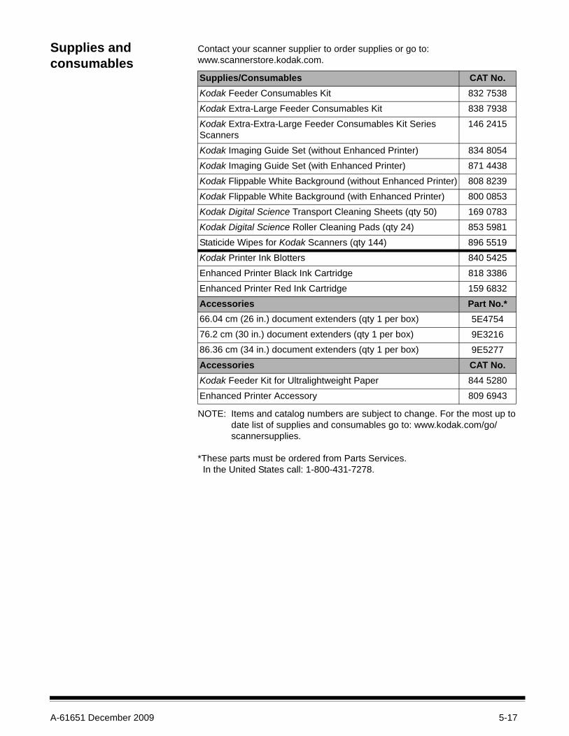
Supplies and consumables
Contact your scanner supplier to order supplies or go to: www.scannerstore.kodak.com.
NOTE: Items and catalog numbers are subject to change. For the most up to date list of supplies and consumables go to: www.kodak.com/go/scannersupplies.
*These parts must be ordered from Parts Services. In the United States call: 1-800-431-7278.
Supplies/Consumables CAT No.Kodak Feeder Consumables Kit 832 7538Kodak Extra-Large Feeder Consumables Kit 838 7938Kodak Extra-Extra-Large Feeder Consumables Kit Series Scanners
146 2415
Kodak Imaging Guide Set (without Enhanced Printer) 834 8054Kodak Imaging Guide Set (with Enhanced Printer) 871 4438Kodak Flippable White Background (without Enhanced Printer) 808 8239Kodak Flippable White Background (with Enhanced Printer) 800 0853Kodak Digital Science Transport Cleaning Sheets (qty 50) 169 0783Kodak Digital Science Roller Cleaning Pads (qty 24) 853 5981Staticide Wipes for Kodak Scanners (qty 144) 896 5519Kodak Printer Ink Blotters 840 5425Enhanced Printer Black Ink Cartridge 818 3386Enhanced Printer Red Ink Cartridge 159 6832Accessories Part No.*66.04 cm (26 in.) document extenders (qty 1 per box) 5E475476.2 cm (30 in.) document extenders (qty 1 per box) 9E321686.36 cm (34 in.) document extenders (qty 1 per box) 9E5277Accessories CAT No.Kodak Feeder Kit for Ultralightweight Paper 844 5280Enhanced Printer Accessory 809 6943

A-61651 December 2009 6-1
6 Troubleshooting
Contents Problem solving .........................................................................................6-1Indicator lights and error codes..................................................................6-3Upgrading software ....................................................................................6-4Contacting Service .....................................................................................6-4
Problem solving Use the chart below as a guide to check possible solutions to problems you may encounter when using the Kodak i4000 Series Scanner.
Problem Possible SolutionDocuments are jamming or multiple documents are feeding
Make sure that:• all documents meet specifications for size, weight, and type, etc. as
outlined in Appendix A, Specifications.• all staples and paper clips have been removed from the documents.• all rollers and tires are clean and the separation roller and feed module
are properly installed. See the procedures in Chapter 5, Maintenance.To remove a document jam:• Remove any documents from the feeder area.• Open the scanner cover.• Locate the jammed document(s) and remove it.• Close the scanner cover and resume scanning.
U9 (document jam) is being displayed in the function window and paper is stopping in the transport, but is not jamming.
Verify that the Document Management: Maximum Length option on the Device-General tab (TWAIN Datasource) or the Longest Document option on the Scanner tab (ISIS Driver) is set to longer than the longest document being scanned. The default is 43.2 cm (17 inches).
The scanner will not scan/feed documents
Make sure that:• the power cord is plugged in and the power is on.• the power button has been pushed on and the green LED is lit.• the scanner cover is completely closed.• documents are making contact with the feed module and are covering
the paper present sensor.• the last document in the stack does not have black in the area covering
the paper present sensor in the input elevator.• documents meet specifications for size, weight, and type, etc.• for thicker documents, toggle the gap release toggle switch during
feeding.• you check the feed module and separation roller for signs of wear, and
replace these parts if necessary.You can also power the scanner down and power it up again.
Image quality is poor or has decreased Make sure that the scanner and imaging guides are clean. Refer to Chapter 5, Maintenance.

6-2 A-61651 December 2009
Problem Possible Solution0 is displayed in the function window after the scanner is powered on indicating the scanner is not communicating with the PC
Try the following:• Check to be sure the USB cable is in good working condition and is
securely plugged into the PC and USB port. • Be sure the software is loaded.• Verify that the PC is recognizing the scanner.
1. Click Start>Settings>Control Panel>Administrative Tools>Computer Management to display the Computer Management window.
2. Select Device Manager and select your PC.
The Kodak i4200 or i4600 Scanner should be displayed under Imaging Devices.
3. Click Action>Scan for hardware changes.“False” paper jams or multifeeds are occurring
• Make sure that the transport area is clean.
35.6 cm (14 in.) or longer documents are not feeding or are jamming
Make sure the input elevator and output tray extenders are pulled out to provide support for long documents or use the optional document extenders. Also see problem U9 (document jam) on page 6-1.
Scanner is running slow • Your PC may not meet the minimum requirements for the scanner.• Some image processing functions will reduce scanner speed.• Resolution (dpi) setting may be set too high.• Your virus software may be scanning all TIFF or JPEG files.• Ensure you are scanning to a local drive.
Documents are skewed during scanning
Make sure that:• the input elevator side guides are adjusted to fit the documents being
fed.• documents are being fed perpendicular to the feed module.• all staples and paper clips have been removed from the documents.• the feed module, separation roller, and drive rollers are clean.• the scanner cover is firmly closed.
Scanner pauses excessively during scanning
Make sure that:• the host computer meets minimum requirements for scanning.• there is enough free space on the hard disk drive.• all other applications are closed.• you are using a USB 2.0 connection.You can also try changing the scanning options (compression, etc.) in your scanning application.

A-61651 December 2009 6-3
Indicator lights and error codes
Steady green: the scanner is scanning.
Fast flashing green: waiting for operator action.
Slow flashing green: the scanner is in power saver mode.
Steady red: indicates a scanner error, such as the scanner cover is open.
Steady red then flashing green — scanner is powering up.
After you power up the scanner, the red and green indicator lights flash. After approximately 12 seconds, both lights go out. When the green indicator light comes back on and the function window displays “1”, the scanner is ready to begin scanning. However, the host computer may require several seconds to detect the scanner.
Falling bar — when the scanner is waiting for an operator action, a blue bar will step down in succession from top to bottom in the function window.
Problem Possible SolutionRoller marks or streaks appear on documents after scanning
Clean the feed module, separation roller and tires. Refer to Chapter 5, Maintenance.
Vertical lines appear on the image • Clean the imaging guides. Refer to Chapter 5, Maintenance.• Enable the Streak Filter option or increase the aggressiveness.
Documents are multifeeding Make sure that:• the leading edges of all batched documents are centered in the feeder
so that each document will come in contact with the feed rollers.• the feed module and separation roller are clean and not worn.• documents with an unusual texture or surface are fed manually.• the gap release toggle switch is not pushed in.
U3 is displayed in the function window The document(s) you are trying to scan is too long.• Verify that the Document Management: Maximum Length option on
the Device-General tab (TWAIN Datasource) or the Longest Document option on the Scanner tab (ISIS Driver) is set to longer than the longest document being scanned. The default is 43.2 cm (17 inches).
• Decrease the resolution.
6-4 A-61651 December 2009
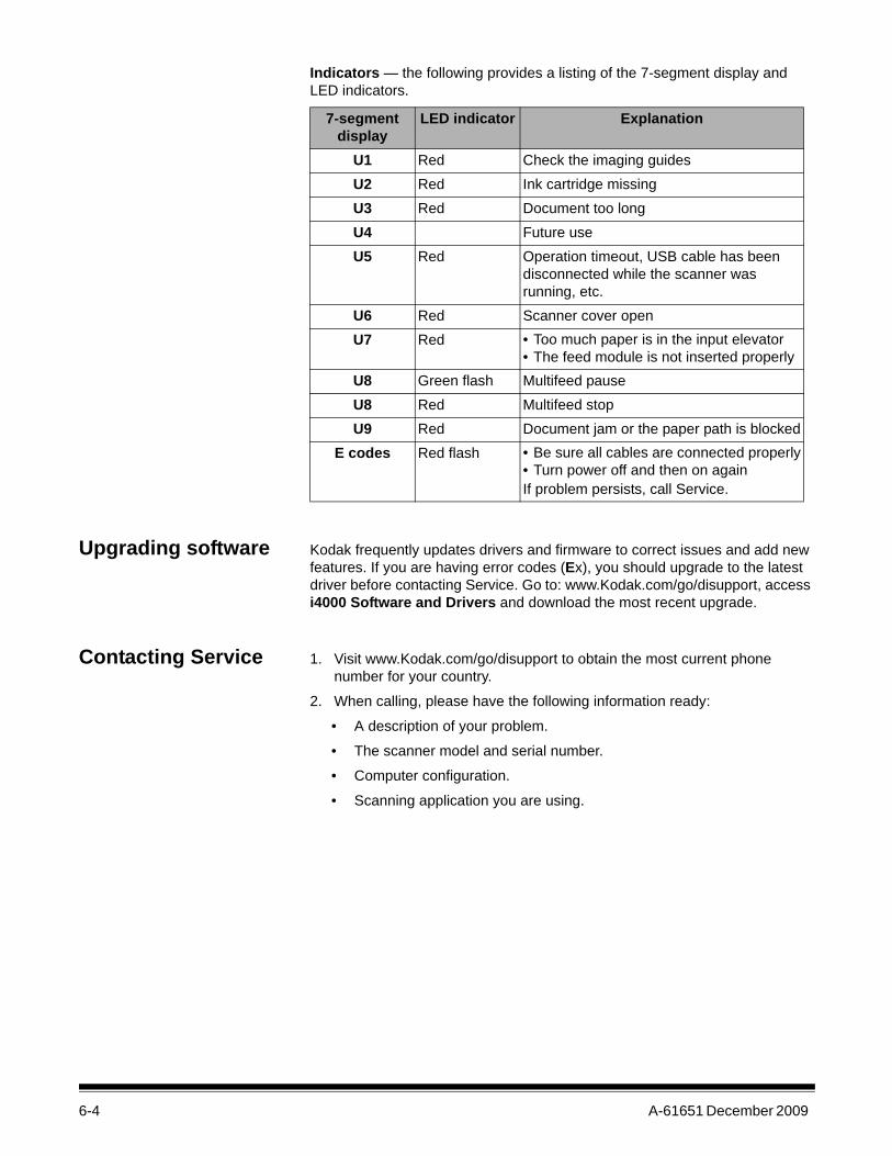
Indicators — the following provides a listing of the 7-segment display and LED indicators.
Upgrading software Kodak frequently updates drivers and firmware to correct issues and add new features. If you are having error codes (Ex), you should upgrade to the latest driver before contacting Service. Go to: www.Kodak.com/go/disupport, access i4000 Software and Drivers and download the most recent upgrade.
Contacting Service 1. Visit www.Kodak.com/go/disupport to obtain the most current phone number for your country.
2. When calling, please have the following information ready:
• A description of your problem.
• The scanner model and serial number.
• Computer configuration.
• Scanning application you are using.
7-segment display
LED indicator Explanation
U1 Red Check the imaging guidesU2 Red Ink cartridge missingU3 Red Document too longU4 Future useU5 Red Operation timeout, USB cable has been
disconnected while the scanner was running, etc.
U6 Red Scanner cover openU7 Red • Too much paper is in the input elevator
• The feed module is not inserted properlyU8 Green flash Multifeed pauseU8 Red Multifeed stopU9 Red Document jam or the paper path is blocked
E codes Red flash • Be sure all cables are connected properly• Turn power off and then on againIf problem persists, call Service.

A-61651 December 2009 A-1
Appendix A Specifications
Scanner Type/Speed • i4200 Scanner: duplex color scanner with an automatic document feeder, 100 pages per minute (landscape) at 200 dpi; black and white.
• i4600 Scanner: duplex color scanner with an automatic document feeder, 120 pages per minute (landscape) at 200 dpi; black and white.
Scanning Technology Dual CCDOutput Resolutions 100, 150, 200, 240, 300, 400 and 600 dpiFile Format Output TIFF, JPEG, PDF (with bundled software)Scan Area Scans up to 30.5 x 330.2 cm (12 x 130 inches). See the section entitled,
“System requirements” for more information.ADF Capacity 500 sheetsRecommended Daily Volume
i4200: 30,000 pages per dayi4600: 50,000 pages per day
Illumination LEDElectrical Requirements 100 - 240 V (international), 50/60 HzScanner Dimensions Height: 34.94 cm (13.7 in.)
Width: 46.0 cm (18.1 in.)Depth: 46.7 cm (18.4 in.)
Scanner Weight 34.28 kg (75.6 lb.)Host Connection Hi-speed USB 2.0Operating Temperature 15°C to 35°C (59°F to 95°F)Humidity 15 to 76% relative humidity Environmental Factors Energy Star qualified scannersPower Consumption - Scanner
Sleep mode: <3 wattsRunning: <85 wattsOff: <0.5 watt
Acoustic Noise(Sound Power level)
Operating: less than 66 dBOff mode or Ready mode: less than 51 dB
Electrical rating 1/N/PE ~ 100 -240 VAC 1.0 - 0.5A 50/60 Hz

A-2 A-61651 December 2009
System requirements Following is the recommended system configuration to run Kodak i4000 Series Scanners.• PC: Intel Core 2 duo, 2 GHz per core• USB port 2.0 high speed• 2 GB RAM• Supported operating systems:
- Microsoft Windows XP (Home and Professional); SP2 and higher- Microsoft Windows XP Professional x64 Edition; SP2 and higher- Microsoft Windows Vista; SP1 and higher- Microsoft Windows Vista x64 Edition- Microsoft Windows 7 (Home and Professional)- Microsoft Windows 7 x64 Edition (Home and Professional)
Included Drivers:• Windows operating systems: TWAIN, ISIS, WIA

A-61651 December 2009 B-1
Appendix B Warranty - US and Canada only
Congratulations on the purchase of a Kodak Scanner. Kodak Scanners are designed to provide end users with the highest performance and reliability. All Kodak Scanners are covered by the following Limited Warranty.
Limited Warranty for Kodak ScannersEastman Kodak Company provides the following Limited Warranty on Kodak Scanners (excluding spare parts and consumables) distributed by Kodak or through Kodak’s authorized distribution channels:
Kodak warrants that a Kodak Scanner, from the time of sale through the Limited Warranty period applicable to the Product, will be free of defects in materials or workmanship and will conform to the performance specifications applicable for the particular Kodak Scanner.
All Kodak Scanners are subject to the Warranty Exclusions described below. A Kodak Scanner found to be defective or which does not conform to the product specifications will be repaired or replaced with new or refurbished product at Kodak’s option.
Purchasers may determine the applicable Limited Warranty period for the Kodak Scanners purchased by calling (800) 822-1414, or by visiting www.Kodak.com/go/disupport or by reviewing the Limited Warranty Summary Card enclosed with the Kodak Scanner.
Proof of purchase is required to demonstrate eligibility for warranty service.
Warranty exclusionsKodak’s Limited Warranty does not apply to a Kodak Scanner that has been subjected to physical damage after purchase, caused, for example, by casualty, accident, acts of God or transportation, including (a) by a failure to properly package and ship the Scanner back to Kodak for warranty service in accordance with Kodak’s then current Packaging and Shipping Guidelines, including failure to replace the shipping restraint prior to shipping, or by a failure to remove the shipping restraint prior to use; (b) resulting from the user’s installation, system integration, programming, re-installation of user operating systems or applications software, systems engineering, relocation, reconstruction of data, or removal of the product or any component (including breakage of a connector, cover, glass, pins, or seal); (c) from service, modification or repair not performed by Kodak or a service provider authorized by Kodak or by tampering, use of counterfeit or other non-Kodak components, assemblies, accessories, or modules; (d) by misuse, unreasonable handling or maintenance, mistreatment, operator error, failure to provide proper supervision or maintenance, including use of cleaning products or other accessories not approved by Kodak or use in contravention of recommended procedures or specifications; (e) by environmental conditions (such as excessive heat or other unsuitable physical operating environment), corrosion, staining, electrical work external to the product or failure to provide electro-static discharge (ESD) protection; (f) by failure to install firmware updates or releases available for the product and (g) by such other supplemental exclusions published from time to time online at www.Kodak.com/go/disupport or by calling (800) 822-1414.
Kodak provides no Limited Warranty for products purchased from countries other than the United States. Purchasers of products from foreign distribution channels must seek warranty coverage, if any, through the original source of purchase.
Kodak provides no Limited Warranty for products that are purchased as part of a third party manufacturer’s product, computer system or other electronic device.
Any warranty for these products is provided by the OEM (Original Equipment Manufacturer) as part of that manufacturer’s product or system.
The replacement product assumes the remainder of the Limited Warranty period applicable to the defective product or thirty (30) days, whichever is longer.
Installation Warning and DisclaimerKODAK WILL NOT BE RESPONSIBLE FOR ANY CONSEQUENTIAL OR INCIDENTAL DAMAGES RESULTING FROM THE SALE, INSTALLATION, USE, SERVICING OR IMPROPER FUNCTIONING OF THIS PRODUCT, REGARDLESS OF THE CAUSE. SUCH DAMAGES FOR WHICH KODAK WILL NOT BE RESPONSIBLE, INCLUDE, BUT ARE NOT LIMITED TO, LOSS OF REVENUE OR PROFIT, LOSS OF DATA, DOWNTIME COSTS, LOSS OF USE OF THE PRODUCT, COST OF ANY SUBSTITUTE PRODUCT, FACILITIES OR SERVICES OR CLAIMS OF CUSTOMERS FOR SUCH DAMAGES.
If there is any conflict between other sections of this appendix and the Limited Warranty, the terms of the Limited Warranty prevail.

B-2 A-61651 December 2009
How to obtain Limited Warranty service Kodak Scanners are supplied with information on unpacking, setup, installation and operation. Careful reading of the User’s Guide will answer most of the technical questions the end user might have regarding proper installation, operation and maintenance of the product. However, should additional technical support be required, you may visit our website at: www.Kodak.com/go/disupport or contact:
Kodak’s Response Center: (800) 822-1414The Response Center is available Monday – Friday (excluding Kodak holidays) 8 a.m. to 5 p.m. EST.
Before placing the call, the eligible purchaser should have the Kodak Scanner model number, part number, serial number and proof of purchase available. The eligible purchaser should also be prepared to provide a description of the problem.
Response Center personnel will assist the end user in resolving the problem over the phone. The end user may be asked to run some simple, self-diagnostic tests and report the resulting status and error code messages. This will assist the Response Center in determining if the problem is the Kodak Scanner or another component and if the problem can be resolved over the phone. If the Response Center determines a hardware problem exists that is covered either under the Limited Warranty or a purchased Maintenance Agreement, a Return Material Authorization Number (RMA) will be assigned as needed, a service request will be initiated and repair or replacement procedures will follow.
Packaging and shipping guidelinesPurchaser must ship all warranty returns in a method that guarantees full protection of the product from shipping damage. Failure to do so will void the Kodak Scanner warranty. Kodak advises the purchaser to keep the original box and packing materials for storing or shipping. Kodak is not responsible for issues related to shipping damage. The purchaser must return only the Kodak Scanner. Prior to shipment, purchaser must remove and retain all “add-on” items, (i.e. adapters, cables, software, manuals, etc.). Kodak accepts no responsibility for these items and they will not be returned with the repaired or replacement Kodak Scanner. All products should be returned to Kodak in the original shipping container, or an authorized packaging box for the units being returned. Purchaser must install the shipping restraint before the Kodak Scanner is shipped. When the original packaging is not available, contact Kodak’s Response Center at (800) 822-1414 for part numbers and replacement packaging ordering information.
Return procedureEligible purchasers seeking services for Kodak Scanners covered under this Limited Warranty must obtain a Return Material Authorization number (“RMA”) by calling (800) 822-1414 and within ten (10) business days from the date of issuance of the RMA must return the Kodak Scanner to the address designated in the RMA at the end user’s own expense and risk, in compliance with Kodak’s current Packaging and Shipping Guidelines.
Any defective products or parts replaced by Kodak become the property of Kodak.
Customer responsibilityBY REQUESTING SERVICE, THE ELIGIBLE PURCHASER ACKNOWLEDGES THE TERMS OF THE LIMITED WARRANTY, INCLUDING THE DISCLAIMER AND LIMITATION OF LIABILITY PROVISIONS. PRIOR TO SEEKING SERVICE, THE END USER MUST BACK-UP ANY DATA OR FILES THAT MAY BECOME DAMAGED OR LOST. KODAK IS, WITHOUT LIMITATION, NOT RESPONSIBLE FOR LOST OR DAMAGED DATA OR FILES.
Warranty Service descriptions Eastman Kodak Company (Kodak) offers a range of service programs to support its Limited Warranty and to assist with the use and care of the Kodak Scanner (“Service Methods”). A Kodak Scanner represents an important investment. Kodak Scanners provide the productivity needed to stay competitive. The sudden loss of this productivity, even temporarily, could seriously affect the ability to meet commitments. Downtime can be very expensive, not just in the cost of the repair but also in time lost. To help alleviate these problems, Kodak may use one of the service methods listed below, depending upon product type, in providing service under its Limited Warranty.
Included with selected Kodak Scanners is a Limited Warranty Registration card and a Limited Warranty Summary card. The Limited Warranty Summary card is specific by model. The Limited Warranty Summary card contains important warranty information, including the model number and the Limited Warranty. Refer to the Limited Warranty Summary card to determine the available Service Methods applicable to the particular Kodak Scanner.
If the Limited Warranty Registration card or Limited Warranty Summary card cannot be located, additional information may be obtained about the product, including updated warranty and service program information and restrictions, online at www.Kodak.com/go/disupport or by phone at (800) 822-1414.
To avoid service delays, Kodak urges end users to complete and return the enclosed Limited Warranty Registration Card at the first opportunity. If you cannot locate the Limited Warranty Registration card, you may register online at www.Kodak.com/go/disupport or by phone at (800) 822-1414.
Kodak also provides a variety of service programs that may be purchased to assist with the use and care of the Kodak Scanner.
Kodak is committed to providing its customers with quality, performance, reliability and service under the Limited Warranty.

A-61651 December 2009 B-3
On-site serviceFor the selected Kodak Scanner, and after the Response Center verifies a hardware problem, a service call will be opened and logged. An Kodak Field Engineer will be dispatched to the product location to perform repair service if the product is located within the contiguous forty-eight (48) United States, in certain areas of Alaska and Hawaii, and if there are no security, safety or physical requirements that would restrict the Field Engineer’s access to the scanner. For additional information on service areas, visit our website at: www.Kodak.com/go/docimaging. On-Site Service will be provided between the hours of 8 a.m. and 5 p.m. local time, Monday through Friday (excluding Kodak holidays).
AURAUR may be one of the easiest and most comprehensive service offerings in the industry. In the unlikely event of a product defect, for eligible purchasers of certain Kodak Scanners, Kodak will replace that product within two business days.
The AUR provides advance replacement on specific failed or broken Kodak Scanner. To be eligible to take advantage of the AUR, the eligible purchaser must obtain an RMA number, sign an Advance Replacement Agreement and provide a credit card deposit to secure the replacement product. The RMA number should be kept in the event that the status of the replacement product needs to be checked. The eligible purchaser will be asked for the address where the replacement product is to be shipped. The eligible purchaser will also be faxed packing and shipping instructions for the malfunctioning product. The eligible purchaser will then receive a replacement product within 2 business days after the service call initiation and Kodak’s receipt of the signed agreement. The malfunctioning product must be received by Kodak within ten (10) days of the end user’s receipt of the replacement product or the end user’s credit card will be charged the list price of the replacement product. Shipment of replacement Imaging Product will be made at Kodak’s expense and choice of freight carrier. Shipments not made under Kodak’s directions and choice of freight carrier may void the Limited Warranty.
Before the product is returned to Kodak, be sure to remove all options and accessories (which include power cord, documentation, etc.) that are not covered by the Limited Warranty. The box and packaging in which the replacement product was shipped must be used to return the malfunctioning product. If the malfunctioning product is not returned in the box and packaging in which the replacement product was shipped the Limited Warranty may be voided. The Return Material Authorization Number (“RMA”) must be clearly marked on the outside of the box to ensure proper receipt and credit of the defective product.
Depot serviceIf the Kodak Scanner is not eligible for Advance Exchange or On-Site Service, an eligible purchaser may utilize our Depot Repair Service. The eligible purchaser will be instructed to ship the product to the nearest authorized Depot Repair Center. Product must be shipped at the eligible purchaser’s risk and expense to the repair center. Before the product is returned to the repair center, be sure to remove all options and accessories (which include power cord, documentation, etc.) not covered by the Limited Warranty. All products should be returned to Kodak in the original shipping container, or in a recommended packing box. The Kodak Scanner must have the shipping restraint installed before it is shipped. When the original packaging is not available, contact Kodak’s Response Center at (800) 822-1414, for ordering information. Eligible purchasers seeking services for Kodak Scanners must obtain a Return Material Authorization number (“RMA”) by calling (800) 822-1414, and within ten (10) business days from the date of issuance of the RMA must return the Kodak Scanner to the address designated in the RMA at the end user’s own expense and risk. The Return Material Authorization Number (“RMA”) must be clearly marked on the outside of the box to ensure proper receipt and credit of the defective product.
Upon receipt of the product, the repair center will repair product within ten (10) business days. The repaired product will be shipped back two-day express mail at no expense to the eligible purchaser.
Important restrictionsEligibility: The Advance Exchange Program and the Depot Service are available to eligible purchasers in the fifty (50) United States, and On-Site Service is available in the contiguous forty-eight (48) states and in certain areas of Alaska and Hawaii for products purchased from authorized distributors of Kodak. The Kodak Scanner will be ineligible for any service under warranty if the product falls under any of Kodak’s then-current Warranty Exclusions, including a purchaser’s failure to return defective products to Kodak in compliance with Kodak’s then current Packaging and Shipping Guidelines. Persons are only considered “eligible purchasers” or “end users” if they originally purchased the Kodak Scanner for their own personal or business use, and not for resale.
Consumables: Consumables are items that wear out under normal use and must be replaced by the end user as needed. Consumables, supplies, other expendable items and those items identified as being the user’s responsibility in the User’s Guide are not covered under the Limited Warranty.
If any of the above excluded parts or services are required, they may be available through an authorized service provider at their hourly rates and at terms then in effect.
Any defective products or parts replaced by Kodak become the property of Kodak.

B-4 A-61651 December 2009
Contacting Kodak For Information on Kodak Scanners:
Website: www.Kodak.com/go/docimaging
For U.S. Service, Repair and Technical Assistance by Telephone:
Telephone technical support is available Monday-Friday between the hours of 5 a.m. to 5 p.m. excluding Kodak holidays. Phone: (800) 822-1414
For Technical Documentation and FAQ’s available 24 hours a day:
Website: www.Kodak.com/go/docimaging
For Service Program Information
Website: www.Kodak.comPhone: (800) 822-1414
