iaea tecdoc series · iaea-tecdoc-1852 iaea-tecdoc-1852 iaea tecdoc series dissimilar metal weld...
TRANSCRIPT

International Atomic Energy AgencyVienna
ISBN 978-92-0-105618-4ISSN 1011–4289
Dissimilar Metal Weld Inspection, Monitoring and Repair Approaches
@
IAEA-TECDOC-1852
IAEA-TECDOC-1852
IAEA TECDOC SERIES
Dissim
ilar Metal W
eld Inspection, Monitoring and Repair Approaches
IAEA-TECDOC-1852

DISSIMILAR METAL WELD INSPECTION, MONITORING AND REPAIR APPROACHES
AFGHANISTANALBANIAALGERIAANGOLAANTIGUA AND BARBUDAARGENTINAARMENIAAUSTRALIAAUSTRIAAZERBAIJANBAHAMASBAHRAINBANGLADESHBARBADOSBELARUSBELGIUMBELIZEBENINBOLIVIA, PLURINATIONAL
STATE OFBOSNIA AND HERZEGOVINABOTSWANABRAZILBRUNEI DARUSSALAMBULGARIABURKINA FASOBURUNDICAMBODIACAMEROONCANADACENTRAL AFRICAN
REPUBLICCHADCHILECHINACOLOMBIACONGOCOSTA RICACÔTE D’IVOIRECROATIACUBACYPRUSCZECH REPUBLICDEMOCRATIC REPUBLIC
OF THE CONGODENMARKDJIBOUTIDOMINICADOMINICAN REPUBLICECUADOREGYPTEL SALVADORERITREAESTONIAESWATINIETHIOPIAFIJIFINLANDFRANCEGABONGEORGIA
GERMANYGHANAGREECEGRENADAGUATEMALAGUYANAHAITIHOLY SEEHONDURASHUNGARYICELANDINDIAINDONESIAIRAN, ISLAMIC REPUBLIC OF IRAQIRELANDISRAELITALYJAMAICAJAPANJORDANKAZAKHSTANKENYAKOREA, REPUBLIC OFKUWAITKYRGYZSTANLAO PEOPLE’S DEMOCRATIC
REPUBLICLATVIALEBANONLESOTHOLIBERIALIBYALIECHTENSTEINLITHUANIALUXEMBOURGMADAGASCARMALAWIMALAYSIAMALIMALTAMARSHALL ISLANDSMAURITANIAMAURITIUSMEXICOMONACOMONGOLIAMONTENEGROMOROCCOMOZAMBIQUEMYANMARNAMIBIANEPALNETHERLANDSNEW ZEALANDNICARAGUANIGERNIGERIANORWAYOMANPAKISTAN
PALAUPANAMAPAPUA NEW GUINEAPARAGUAYPERUPHILIPPINESPOLANDPORTUGALQATARREPUBLIC OF MOLDOVAROMANIARUSSIAN FEDERATIONRWANDASAINT VINCENT AND
THE GRENADINESSAN MARINOSAUDI ARABIASENEGALSERBIASEYCHELLESSIERRA LEONESINGAPORESLOVAKIASLOVENIASOUTH AFRICASPAINSRI LANKASUDANSWEDENSWITZERLANDSYRIAN ARAB REPUBLICTAJIKISTANTHAILANDTHE FORMER YUGOSLAV
REPUBLIC OF MACEDONIATOGOTRINIDAD AND TOBAGOTUNISIATURKEYTURKMENISTANUGANDAUKRAINEUNITED ARAB EMIRATESUNITED KINGDOM OF
GREAT BRITAIN AND NORTHERN IRELAND
UNITED REPUBLICOF TANZANIA
UNITED STATES OF AMERICAURUGUAYUZBEKISTANVANUATUVENEZUELA, BOLIVARIAN
REPUBLIC OF VIET NAMYEMENZAMBIAZIMBABWE
The following States are Members of the International Atomic Energy Agency:
The Agency’s Statute was approved on 23 October 1956 by the Conference on the Statute of the IAEA held at United Nations Headquarters, New York; it entered into force on 29 July 1957. The Headquarters of the Agency are situated in Vienna. Its principal objective is “to accelerate and enlarge the contribution of atomic energy to peace, health and prosperity throughout the world’’.

IAEA-TECDOC-1852
DISSIMILAR METAL WELD INSPECTION, MONITORING AND REPAIR APPROACHES
INTERNATIONAL ATOMIC ENERGY AGENCYVIENNA, 2018

COPYRIGHT NOTICE
All IAEA scientific and technical publications are protected by the terms of the Universal Copyright Convention as adopted in 1952 (Berne) and as revised in 1972 (Paris). The copyright has since been extended by the World Intellectual Property Organization (Geneva) to include electronic and virtual intellectual property. Permission to use whole or parts of texts contained in IAEA publications in printed or electronic form must be obtained and is usually subject to royalty agreements. Proposals for non-commercial reproductions and translations are welcomed and considered on a case-by-case basis. Enquiries should be addressed to the IAEA Publishing Section at:
Marketing and Sales Unit, Publishing SectionInternational Atomic Energy AgencyVienna International CentrePO Box 1001400 Vienna, Austriafax: +43 1 26007 22529tel.: +43 1 2600 22417email: [email protected] www.iaea.org/books
For further information on this publication, please contact:
Nuclear Power Engineering SectionInternational Atomic Energy Agency
Vienna International CentrePO Box 100
1400 Vienna, AustriaEmail: [email protected]
© IAEA, 2018Printed by the IAEA in Austria
September 2018
IAEA Library Cataloguing in Publication Data
Names: International Atomic Energy Agency.Title: Dissimilar metal weld inspection, monitoring and repair approaches / International
Atomic Energy Agency.Description: Vienna : International Atomic Energy Agency, 2018. | Series: IAEA TECDOC
series, ISSN 1011–4289 ; no. 1852 | Includes bibliographical references.Identifiers: IAEAL 18-01179 | ISBN 978–92–0–105618–4 (paperback : alk. paper)Subjects: LCSH: Nuclear reactors — Maintenance and repair. | Nuclear power plants. |
Dissimilar welding. | Stress corrosion.

FOREWORD
Dissimilar metal welds (DMWs) are common in light water reactors at the interfaces between ferritic components and austenitic piping systems and other structural elements. The most important property of DMWs with respect to residual stresses is the difference in the coefficients of thermal expansion between the parent and weld metals.
DMWs in safety critical locations include the connections from the reactor pressure vessel, the steam generator and the pressurizer of the primary circuit, and safety system piping and vessel penetrations (e.g. for the control rod drive mechanism and instrumentation).
Various forms of cracking have been observed in DMWs between piping components in nuclear power plants. Mixed mode loading, inspection difficulties, variability of material properties, residual stresses and conservatism of current engineering methods all combine to create problems for structural integrity assessment.
Recent operating experience in IAEA Member States (e.g. at Kernkraftwerk Leibstadt and Biblis in Germany, at Ringhals in Sweden, and at various EDF plants) has shown that these welds can be susceptible to various forms of service induced cracking. When such cracking is detected, usually during non-destructive examination, the operator has to make an assessment of the situation depending on the extent and severity of the reported damage. Depending on the safety class of the equipment, the results must be presented and reported to the regulatory body.
This publication is aimed at inspection organizations and their managers, operating staff and the local suppliers who provide inspection services for utilities. It aims to share good practices, as well as some practical case studies, for use by operators and utilities in Member States. The publication discusses requirements for an in-service inspection programme; different inspection techniques and methods; inspection qualification and evaluation of results; and challenges for ultrasonic inspection of DMWs. It also discusses techniques for repairing and replacing DMWs, as well as how to mitigate or remove cracks and corrosion that might have an impact on the safety margins.
The information included represents a general consensus among the participating experts as to the best common or individual practices for use at nuclear power plants for the inspection and repair of DMWs.
The IAEA wishes to thank all the experts involved and their Member States for their contributions. The IAEA officer responsible for the preparation of this publication was H. Varjonen of the Division of Nuclear Power.
EDITORIAL NOTE
This publication has been prepared from the original material as submitted by the contributors and has not been edited by the editorial staff of the IAEA. The views expressed remain the responsibility of the contributors and do not necessarily represent the views of the IAEA or its Member States.
Neither the IAEA nor its Member States assume any responsibility for consequences which may arise from the use of this publication. This publication does not address questions of responsibility, legal or otherwise, for acts or omissions on the part of any person.
The use of particular designations of countries or territories does not imply any judgement by the publisher, the IAEA, as to the legal status of such countries or territories, of their authorities and institutions or of the delimitation of their boundaries.
The mention of names of specific companies or products (whether or not indicated as registered) does not imply any intention to infringe proprietary rights, nor should it be construed as an endorsement or recommendation on the part of the IAEA. .
The IAEA has no responsibility for the persistence or accuracy of URLs for external or third party Internet web sites referred to in this publication and does not guarantee that any content on such web sites is, or will remain, accurate or appropriate.

CONTENTS
1. INTRODUCTION ............................................................................................................ 1
1.1. Background ......................................................................................................... 1 1.2. Objectives ........................................................................................................... 5 1.3. Scope .................................................................................................................. 6 1.4. Structure .............................................................................................................. 6
2. REVIEW OF DMW NUCLEAR INDUSTRY OPERATING EXPERIENCES ............. 6
2.1. Introduction ........................................................................................................ 6 2.1.1. The phenomenon of stress corrosion cracking (SCC) ............................ 8
2.2. Difficulties in ultrasonic inspection of DMW’S ............................................... 13
3. IN–SERVICE INSPECTION REQUIREMENTS AND IMPLEMENTATION ........... 14
3.1. Inspection programme ...................................................................................... 14 3.2. In–service inspection programmes review and up–to–date .............................. 16 3.3. Recommended input parameters for inspections .............................................. 17 3.4. Inspection techniques ....................................................................................... 19 3.5. Inspection qualification .................................................................................... 21
3.5.1. Background ........................................................................................... 21 3.5.2. Qualification of equipment ................................................................... 22 3.5.3. Qualification of NDE procedure ........................................................... 22 3.5.4. Modelling .............................................................................................. 24 3.5.5. Test pieces in practical demonstrations ................................................ 25 3.5.6. Qualification of NDE personnel ........................................................... 25
3.6. Evaluation of inspection results ........................................................................ 27 3.6.1. Background information and introduction ............................................ 27 3.6.2. Acceptance standards and methods ...................................................... 30 3.6.3. Exceeding threshold set in acceptance standards ................................. 31 3.6.4. Fracture mechanical analyses ............................................................... 32 3.6.5. Root cause analysis ............................................................................... 33
4. REPAIR, REPLACEMENT OR MITIGATION ............................................................ 36
4.1. Background ....................................................................................................... 36 4.2. Weld repair technique considerations ............................................................... 37
4.2.1. PWSCC susceptible locations ............................................................... 37 4.2.2. SCC susceptible locations in BWRs ..................................................... 39 4.2.3. PWSCC susceptible locations in WWER ............................................. 39
4.3. Repair techniques ............................................................................................. 40 4.3.1. Welding repair techniques .................................................................... 41
4.4. Repair plan ........................................................................................................ 55 4.4.1. Repair method development ................................................................. 56 4.4.2. Development and variations of Filler Metal 52 [48] ............................ 60 4.4.3. Qualification of welding procedure ...................................................... 61 4.4.4. Demonstration mock–up ....................................................................... 61 4.4.5. Inspection .............................................................................................. 65
4.5. Qualification of pre–service inspection ............................................................ 65 4.6. Repair and implementation ............................................................................... 66
4.6.1. Construction and inspection plan .......................................................... 66 4.6.2. Quality assurance programme .............................................................. 67

4.6.3. Vendor oversight / supervision ............................................................. 68 4.6.4. Before repair / replacement activity (mock–up welds) ......................... 68 4.6.5. During the repair / replacement activities ............................................. 69
5. OPERATING EXPERIENCES, LESSONS LEARNED AND RECOMMENDATIONS ................................................................................................ 69
5.1. Arkansas one (pwr) half nozzle repair .............................................................. 73 5.2. Weld overlay using code case n–504 ............................................................... 74 5.3. Davis Besse (pwr) full structural weld overlays ............................................... 75 5.4. Palo Verde (PWR) mechanical nozzle seal assemblY ..................................... 75
REFERENCES ......................................................................................................................... 77
GLOSSARY ............................................................................................................................. 79
ABBREVIATIONS .................................................................................................................. 81
ANNEX I: INSPECTION DATA SHEET ............................................................................... 85
ANNEX II: MODELLING CASE STUDY ............................................................................. 87
ANNEX III: THE WELD STRUCTURE MODEL ................................................................. 89
ANNEX IV: REPAIR STRATEGIES BASED ON UT EXAMNINATIONS WITHIN WWER TYPE NPP’S ..................................................................................................... 95
ANNEX V: WELD OVERLAY OPERATING EXPERIENCE ........................................... 101
CONTRIBUTORS TO DRAFTING AND REVIEW ........................................................ 111

1
1. INTRODUCTION
During the last few decades welds between ferritic and austenitic materials challenged manufacturers and inspectors in nuclear power plants and other boiler operators all over the world. It has been recognized that defects and failures in this kind of welded joints can cause dangerous situations and as well unscheduled outages in nuclear power plants.
Nuclear power plant (NPP) ferritic steel pipe–nozzles in primary systems like reactor pressure vessels (RPV) and steam generators (SG) are connected with dissimilar metal weld’s (DMW) to the austenitic stainless steel Safe Ends. The most common filler material in these dissimilar metal welding’s (DMW) is a nickel–base alloy 82 / 182, because its thermal coefficient is roughly midway between those of ferritic — and austenitic stainless steel. In addition, the use of Alloy 82 / 182 for buttering allows post weld heat treatment (PWHT) of the nozzle to be done in the shop. This makes installation easier since the DMW between the safe end and nozzle (butter) eliminates any additional PWHT.
For WWER–440 and WWER–1000 type reactors, the location of DMWs is in general similar to the locations mentioned at PWRs and BWRs. The principal difference is in the applied materials and much less in their locations. There is also substantial difference in the base metal materials for WWER–440 and WWER–1000 primary circuit piping. Austenitic stainless steel 08Kh18N10T respectively ferritic steel 22K equipped with austenitic cladding is applied for WWER–440 respectively WWER–1000 primary piping. The austenitic stainless steel filler EA410T and the buttering the 1st layer material Sv–10Kh16N25AM6 and the buttering 2nd layer material Sv–04Kh19N11M3 are applied for WWER–440 and WWER–1000 type NPPs. The locations where DMWs are typically found include WWER–440 RPV safe end welds, recirculation inlet and outlet SG nozzles, core spray nozzles, jet pump instrumentation nozzles, and feedwater nozzles.
Operating experiences and continuous research in this difficult welding area has identified few different failure modes, which continue to cause problems. Now, when many of existing nuclear power plants plan their life time extension from planned 40 years operation to the 60, 70 or even 80 years, it is important to find ways to inspect even more precisely these dissimilar metal welding joints and, if some failures were detected, how to properly repair these findings to ensure reliable operation.
Despite improvements in welding methods as well as with the characteristics of weldable materials, these connections and joints continue to concern the entire industry.
This publication outlines the main aspects and issues to be considered when developing and improving dissimilar metal weld (DMW) inspections in NPPs. It also provides in–service inspection (ISI) requirements for DMW’s in NPPs and describes challenges which may occur during inspections.
1.1.BACKGROUND
Several thousand successful non–destructive tests are performed annually in nuclear power plants. Yet there is still much to improve and develop in the performance of technical inspections and as well as the evaluation / analysis of the results.
A large number of welded connections are used in nuclear power plants to achieve the best possible mechanical strength. Reactor pressure vessel (RPV) components are made of ferritic steel, whereas some of the connecting pipelines are fabricated from austenitic stainless steel.

2
As a consequence, different components often need to be connected by so–called dissimilar metal welds (DMW). A DMW refers to a weld joining two materials from different alloy systems. A common power plant application is joining a ferritic low alloy steel to an austenitic stainless steel [1]. A schematic of a DMW is shown in Figure 1.
FIG.1. Typical DMW for PWR and BWR.
Under the liberal market conditions prevailing today, it is important to continue to demonstrate that nuclear power plants are safe to use, cost effective and competitive in relation to other energy sources. One of the most critical aspects from the point of view of a pipe rupture is ageing in DMW’s. Due to the complexity of the dissimilar metal welds, undetected defects or discontinuities can exist. The goal of dissimilar metal welding inspection and monitoring in Nuclear Power Plants (NPP) is ensure the structural integrity of the main components throughout the suspected lifetime.
The use of dissimilar metal welding has achieved significant benefits. Many years of operating experience with these joints reveal the potential for defects that may jeopardize the Nuclear Power Plants safety and availability. However, that same experience demonstrates that periodic maintenance and inspection of these welded joints is an essential part of power plant safety, reliability and long term, sustainable operation.
A buttering layer is often used to provide a transition between the considerably different physical and mechanical properties of the parent materials. A power plant application of DMW is given in ASME Boiler and Pressure Vessel Code, Section XI, Rules for In–Service Inspection of Nuclear Power Plant Components, Division1 [1].
Parent material A/C Stainless steel
Weld metal Cladding: Stainless Steel
Buttering Parent material B: Carbon or low alloy steel

3
TABLE 1: EXAMPLES OF DMW JOINT MATERIAL COMPOSITIONS:
PWR/BWR Material
Joint component Material Nominal
composition
Parent A Inconel 600 72 min. Ni 15 Cr 8 Fe
Weld metal Inconel 82 (ERNiCr-3)
Inconel 182 (ENiCrFe-3)
67 min. Ni 20 Cr 3 max. Fe 59 min. Ni 15 Cr 10 max. Fe
Buttering Inconel 82 (ERNiCr-3)
Inconel 182 (ENiCrFe-3)
67 min. Ni 20 Cr 3 max. Fe 59 min. Ni 15 Cr 10 max. Fe
Parent B ASTM A508 Grade 2 steel 0.75 Ni 0.35 Cr 0.65 Mo
Parent C
304 SS
18 Cr 8 Ni Bal Fe
WWER Material
Vessel/Shell SG collector
22K Steel
0.26 max C 0.25 Cr 0.6 Mn 0.23Ni
Vessel: WWER-440 RPV
15Kh2MFA
0.18 max C max: 3.0 Cr 0.8 Mo 0.35 V
1st layer of cladding: WWER RPV
Sv07Kh25N13
25 Cr 13 Ni
2nd layer of cladding: WWER RPV
Sv08Kh19N10
18 Cr 10 Ni Nb
Vessel: WWER-1000 RPV
15Kh2NMFA
0.18 max C max: 2.3 Cr 1.5 Ni 0.7 Mo 0.10 V
Pipe 08Ch18N10T SS
18 Cr 10 Ni 0.7 Ti Bal Fe

4
1st layer of buttering
Original
EA-395/9 SS Sv-10Kh16N25AM6
15 Cr 25 Ni 6 Mo
1st layer of buttering new option Sv-07Ch25N13 25 Cr 25 Ni 13
2nd layer of buttering Sv-04Kh19N11M3 SS 18 Cr 10 Ni 2 Mo
weld metal filler EA-400/10T 18 Cr 10 Ni
The heat–up and cooldown cycles imposes thermal strains on the DMW having stainless steel as filler metal because the thermal expansion coefficients for the stainless steel is about 30% higher than that for ferritic steel. Thus, the mismatch of the thermal expansion coefficients and possibly carbon migration from the ferritic material to the austenitic material (mostly if a PWHT is done) are more likely to shorten the stress corrosion cracking or fatigue crack propagation life of a DMW having stainless steel as a filler metal.
The use of Ni–based alloys as a filler metal has a less adverse effect on the fatigue life of a DMW because of reduced carbon migration and significantly smaller mismatch in the thermal expansion coefficients between the filler metal and carbon steel base material. However, there will be a significant mismatch in the thermal expansion coefficients between the Ni–based filler metal and the stainless steel base material [2].
Detecting these failures is only possible, if reasons and forms of anomalies are known. These welds usually have degradation in the heat affected zone (HAZ) or in the buttering, where material discontinuity cannot be recognized in all cases.
Especially, for interdendritic stress corrosion cracking (IDSCC) in nickel base alloys weld metal, weld repairs seem to be of great influence for cracks to develop.
The difficulty in detecting SCC in Ni–alloy welds depends on the tight shape of the crack opening displacement (COD) and the intermittent crack openings in the surface. The through wall sizing is also a challenge, in part because the crack surfaces in depth are in contact with each other due to the tightness and presence of unbroken ligaments, which cause a number of diffracted signals. The main problem of this is that cracks may be undersized. Many nuclear power plant’s steam generators (SG) were manufactured according to the same welding procedure as the ones having been damaged. Based on the corrosion damage of this type with the electrochemical corrosion initiation process caused by anodic dissolution of carbon steel and with the dominant degradation mechanism the stress corrosion cracking on the dissimilar metal welds of steam generator lower collectors the occurrence of non–destructive examination (NDE) issues with large corrosion damage even through wall cracks with leaks cannot be excluded.
5
Ultrasonic non–destructive inspection of austenitic welds and DMW components is complicated because of anisotropic columnar grains and dendritic structures leading to beam splitting and beam deflection. Qualification plays an important role in developing advanced reliable ultrasonic testing (UT) techniques and optimizing experimental parameters for the inspection of austenitic welds and dissimilar weld components.
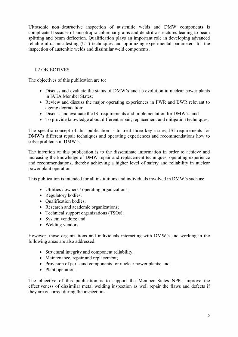
1.2.OBJECTIVES
The objectives of this publication are to:
Discuss and evaluate the status of DMW’s and its evolution in nuclear power plants in IAEA Member States;
Review and discuss the major operating experiences in PWR and BWR relevant to ageing degradation;
Discuss and evaluate the ISI requirements and implementation for DMW’s; and To provide knowledge about different repair, replacement and mitigation techniques;
The specific concept of this publication is to treat three key issues, ISI requirements for DMW’s different repair techniques and operating experiences and recommendations how to solve problems in DMW’s.
The intention of this publication is to the disseminate information in order to achieve and increasing the knowledge of DMW repair and replacement techniques, operating experience and recommendations, thereby achieving a higher level of safety and reliability in nuclear power plant operation.
This publication is intended for all institutions and individuals involved in DMW’s such as:
Utilities / owners / operating organizations; Regulatory bodies; Qualification bodies; Research and academic organizations; Technical support organizations (TSOs); System vendors; and Welding vendors.
However, those organizations and individuals interacting with DMW’s and working in the following areas are also addressed:
Structural integrity and component reliability; Maintenance, repair and replacement; Provision of parts and components for nuclear power plants; and Plant operation.
The objective of this publication is to support the Member States NPPs improve the effectiveness of dissimilar metal welding inspection as well repair the flaws and defects if they are occurred during the inspections.

6
This document provides practical examples and best practices for different techniques of inspections, acceptance limits and criteria for defects and requirements for inspection qualification.
1.3.SCOPE
The scope of this technical document to collect the latest information on the knowledge and practices of DMWs inspections and monitoring practices to improve structural integrity of NPPs.
Relevant topics are:
Monitoring effectiveness of inspection and corrective actions;
Timely remedial actions to arrest continuing or address begin degradation;
Phenomenon of degradation;
Acceptance limits and criteria for defects and flaws, practice and training;
New inspection techniques;
Selection of the appropriate method for inspection;
Techniques for establishing time–dependent changes –> evaluation process;
Evaluation and identification of test results and findings, including development of reporting; and
Repairing of findings and re–inspection after repair.
This document describes code requirements such as ASME Section III and Section XI [1], including coverage of the stainless steel weld and also includes the classification of areas subject to inspection, responsibilities, provision for access, inspection techniques and procedures, qualification of personnel, inspection frequency, documentation, evaluation of results and repair requirements.
1.4.STRUCTURE
The publication is divided into five main sections. Section two gives review of operating experiences and different degradation mechanisms for DMW’s in nuclear industry. Section three describes in–service inspection programmes and different inspection techniques for DMW’s and how to evaluate inspection results. Section four is focused on different repair, replacement and mitigation techniques. Sections five includes a summary of lessons learned, recommendations and a few case studies of DMW’s.
2. REVIEW OF DMW NUCLEAR INDUSTRY OPERATING EXPERIENCES
2.1.INTRODUCTION
This section provides a summary of the major operational PWR and BWR service history relevant to ageing degradation by stress corrosion cracking (SCC) focused on DMWs.

7
These incidents offer a perspective on the design bases and their conservatism relative to operating parameters. It is particularly noteworthy that each has been resolved by a qualified repair programme. Nozzle cracking, stub tube cracking, Safe End cracking and closure stud cracking are all age–related degradation mechanisms; which have been effectively managed. The OECD / NEA SCAP event database (Access is granted from NEA) will provide details of previous SCC events. In the following chapters, we will focus mainly on DMW nuclear industry failures, NDE issues in both BWR and PWR type reactors.
46 NDE issues with some failures investigated can be summarized as follows: 7 RCS nozzle or drain line DMWs, (RCS–reactor coolant system); 7 Pressurizer relief or surge DMWs; 4 Feedwater DMWs; 3 RPV outlet or inlet DMWs; 3 CRDM DMW; 3 Core spray DMW; 3 Safety nozzle DMWs; 2 Surge nozzle DMWs; 2 Decay heat nozzle DMW; 12 other different DMWs.
Detection of NDE indications was performed in many of the above cases by UT (39 of 46), other during walk–down / surveillance or by visual testing (VT) (6 leaks) and the last one during replacement by dye penetrant testing (PT).
Accepted measures include in the majority various kinds of weld overlays (WOL). Seven cases were solved by replacement and / or destructive examination. For five events, monitoring of allowable flaw indications was decided according to the Code requirements. Three flaw indications were acceptable for operation due to the fabrication origin.
The characteristics of failures in DMWs are quite different from those of intergranular stress corrosion cracking (IGSCC) in stainless steel. A prime difference is that the dissimilar metal (DM) flaws are typically located in the weld material, whereas IGSCC is located along the heat–affected zone (HAZ). With DM flaws, the cracking is interdendritic rather than intergranular. The growth pattern can appear to be disconnected or discontinuous.
DMWs are usually wider than normal stainless steel welds. This can lead to difficulties, particularly when the flaw is located on the far side of the weld. Many DMWs at Western type reactors are ground flush, allowing for good access to the weld. Where the DMW is close to (or part of) a diameter or thickness transition, access to the weld might be restricted. DMWs at WWER type reactors are not normally grounds flush, the weld crown in such cases is a significant access restriction especially when the flaw is located on the far side of the weld in the vicinity of the weld buttering or directly on the weld buttering to carbon steel interface.
The DMW flaws at WWER type reactors are not typically located in the weld material, they are prominently located at the weld buttering to carbon steel interface and along the HAZ. With The degradation mechanisms for DM flaws at WWER type reactors are usually combination of corrosion on the carbon steel side and SCC.
8
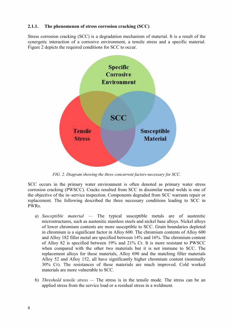
2.1.1. The phenomenon of stress corrosion cracking (SCC)
Stress corrosion cracking (SCC) is a degradation mechanism of material. It is a result of the synergetic interaction of a corrosive environment, a tensile stress and a specific material. Figure 2 depicts the required conditions for SCC to occur.
FIG. 2. Diagram showing the three concurrent factors necessary for SCC.
SCC occurs in the primary water environment is often denoted as primary water stress corrosion cracking (PWSCC). Cracks resulted from SCC in dissimilar metal welds is one of the objective of the in–service inspection. Components degraded from SCC warrants repair or replacement. The following described the three necessary conditions leading to SCC in PWRs.
a) Susceptible material — The typical susceptible metals are of austenitic microstructures, such as austenitic stainless steels and nickel base alloys. Nickel alloys of lower chromium contents are more susceptible to SCC. Grain boundaries depleted in chromium is a significant factor in Alloy 600. The chromium contents of Alloy 600 and Alloy 182 filler metal are specified between 14% and 16%. The chromium content of Alloy 82 is specified between 19% and 21% Cr. It is more resistant to PWSCC when compared with the other two materials but it is not immune to SCC. The replacement alloys for these materials, Alloy 690 and the matching filler materials Alloy 52 and Alloy 152, all have significantly higher chromium content (nominally 30% Cr). The resistances of these materials are much improved. Cold worked materials are more vulnerable to SCC.
b) Threshold tensile stress — The stress is in the tensile mode. The stress can be an applied stress from the service load or a residual stress in a weldment.

9
c) Specific aqueous environment — The occurrence of SCC is very dependent on the temperature, hydrogen concentration and to a lesser extent the Lithium content, pH–value and the presence of zinc [3] SCC is generally considered less credible in PWR at an operating temperature lower than 290oC.
SCC typically shows branched cracks. The cracking morphology of SCC can manifest itself in three forms [4].
a) Intergranular — In this form of crack path, the crack predominantly follows along grain boundaries in materials of wrought forms or the heat affected zone (HAZ) of a weld. SCC taking this form of crack morphology is termed as Intergranular SCC (IGSCC). Figure 3 shows a typical IGSCC. Austenitic stainless steel with sensitized grain structure is susceptible to IGSCC. In the sensitized austenitic stainless steel materials, the grain boundaries are depleted with chromium as a result of formation of complex chromium carbide particles along grain boundaries. The chromium–depleted grain boundaries offer less resistance to corrosion. SCC of alloy 600 in mill annealed condition takes this form of SCC.
b) Transgranular — In this form of crack path, a crack predominantly propagates through grains without a preferential crack path. It is also described as Transgranular SCC (TGSCC). Chloride–induced SCC in austenitic stainless steel has this signature form of cracking morphology. Figure 4 shows a typical transgranular SCC.
c) Interdendritic — This form of crack path can be found in weld deposit consisting of dendritic solidification structure. The crack path tends to follow the interdendritic areas where undesirable microstructural constituents and carbides tend to agglomerate. The interdendritic area can also deplete with chromium. As a result, cracks due to SCC will tend to follow this area in their propagation. SCC showing such crack path patterns is referred to as Interdendritic SCC (IDSCC). SCC of nickel alloy weld deposit in dissimilar metal weld exhibits this form of cracking. This mode of cracking has been seen in WWER DMW. Figure 5 shows a typical interdendritic SCC.
Especially, for interdendritic stress corrosion cracking (IDSCC) in nickel base alloys weld metal, weld repairs seem to significantly influence crack development.
The designation IDSCC indicate that the cracking occurs in weld metal only. Typical orientation is transverse to the weld joint.
Similar to IDSCC in austenitic stainless steels, IDSCC in weld metal shows frequent micro–branching. However, macro–branching is less frequent for IDSCC. Stress corrosion cracking normally produces very sharp crack tips, typically < 1 µm. It is obvious that the crack width doesn’t necessarily decrease with increasing distance from the surface. This appearance is typical for SCC in weld metal. The crack width is varying considerably more along the crack in the thickness direction compared with other crack mechanisms. It is also common that the crack width at the surface is considerably smaller than further below. A crack width close to zero at the intersection with the surface can occur. Due to the three–dimensional (3D) dendritic micro–structure of weld metal, an SCC crack often appears to be discontinuous, when looking at a cross-section. A reasonable

10
explanation is that the growing crack cannot pass through dendrites oriented perpendicular to the crack plane. The crack front must split when it meets the dendrite and is re–joining after passing it. Everywhere the cross–section coincides with such dendrites the crack appears to be discontinuous [4].
FIG. 3. Photomicrograph showing a typical crack path of IGSCC (through wall) (Courtesy of VTT).
FIG. 4. Photomicrograph showing a typical crack path of TGSCC (Courtesy of VTT).

11
FIG. 5. Photomicrograph showing a typical crack path of IDSCC (Courtesy of VTT).
For SCC, as already noted, all three prerequisites; material condition, environment chemistry and stress must be fulfilled. In the original design of LWRs, SCC phenomena were not explicitly considered until, beginning in the mid–seventies, the worldwide BWR fleet began to suffer from a sequence of IGSCC incidents. The ensuing damage resulted in substantial economic losses for utilities, especially in the eighties. A tremendous amount of effort was devoted during the ensuing years to mitigate IGSCC and, in particular, to improve the water chemistry. Due to these efforts, plant availability has increased and, in addition, radiation buildup has been effectively mitigated. The evolution of capacity factor losses, as of 1980, according to Figure 6 reflects that early mistakes have been corrected over time; partly by improving water chemistry but also through component replacements. The dominating early failure type in BWRs was IGSCC of sensitized stainless steel and more recently of cold worked stainless steels; e.g. type 316L. In PWRs, steam generator tube cracking issues were dominant. However, unpredicted SCC attacks still occur and influence plant performance and availability.
FIG. 6: Corrosion related capacity factor losses due to corrosion in BWRs [5].
Dissimilar metal welds on the lower part of the steam generator collectors of WWER–440 nuclear power plants (Figure 7a and 7b) have shown a significant degradation in several facilities in the last third of their design life. The degradation phenomenon is intergranular corrosion attack starting from the internal surface which leads to loss of cohesion of grain boundaries between ferritic collector material and the first layer of the buttering, and then to a large discontinuity. The degradation may occur along the whole circumference and its depth can vary. Its influence on structural integrity needs to be assessed, and in some plants the

12
dissimilar welds have already been repaired, in other plants the extension of ultrasonic examination is planned and further repairs are scheduled based on structural integrity calculations and qualified in–service inspection (ISI) results.
FIG. 7a: Dissimilar metal weld of the steam generator collector [6].
FIG. 7b: Lower part of steam generator [6].
The basic cause of the damage is the strong susceptibility of the interface of the first layer of buttering (austenitic stainless steel to carbon steel) to SCC due to carbon diffusion into the buttering first layer causing non–stabilized steel approximately to the depth of 50μm. Other deficiencies are design failures in the welding procedure in general causing residual stresses to increase due to the post welding heat treatment (PWHT) during the manufacturing phase, the corrosive influence of the secondary medium due to the corrosive deposits occurrence in the crevice and, to less extent, the mechanical loading conditions contribute to the damage.

13
2.2.DIFFICULTIES IN ULTRASONIC INSPECTION OF DMW’s
In PWRs, steam generator tube cracking issues were dominant in the past. For steam generator tube similarly like for RPV safe end welds or other pressurizer or steam generator DMWs SC cracking issues, three main prerequisites; material condition, environment chemistry and stress had to be fulfilled.
Dissimilar metal welds can be found as well in PWR as in BWR plants, and often connect equipment like RPV, SG or pressurizer to the main coolant piping. DMWs of ferritic nozzle to austenitic piping welds are very challenging configurations for UT examination. Various UT beam propagation issues in austenitic structures and the buttering on the carbon steel side has influence on the reliability of inspection. This is due to the presence of multiple acoustic interfaces and the complex geometry (nozzles, tapering, weld surface condition, one side access and weld crown). In the original design of LWRs, SCC phenomena were not explicitly considered. The ensuing damage resulted in substantial economic losses for utilities. The evolution of capacity factor losses reflects that early mistakes have been corrected over time; partly by improving water chemistry but also through component replacements. Unpredicted SCC attacks still occur in PWRs and influence plant performance and availability.
During ultrasonic inspection of anisotropic and inhomogeneous austenitic welds there are some difficulties to which special attention should be paid [6–11].First the elastic properties of the austenitic weld material are directional dependent. Due to the inhomogeneous columnar grain structure, curved ultrasound paths are resulted [7]. One of most significant problems is the scattering of ultrasound at the grain boundaries leads to the high attenuation of the ultrasound beam. Scattering is highly dependent on the relation of grain size to ultrasonic wavelength. When grain size is less than 0.01 times the wavelength, scatter is negligible, and when the grain size is 0.1 times the wavelength or larger, excessive scattering may make it impossible to conduct valid ultrasonic inspections [1]. For this reason, spatially separate low frequency, which gives a longer wave length, sending and receiving transducer arrangement is used for ultrasonic inspection of austenitic welds[7].
When an ultrasound is incident at an interface[7]:
In case of austenitic on weld materials between two adjacent anisotropic columnar grains resulting three reflected and three transmitted waves, and
In case of isotropic ferritic two transverse waves are degenerate and coupling exists only between longitudinal and shear vertical waves.
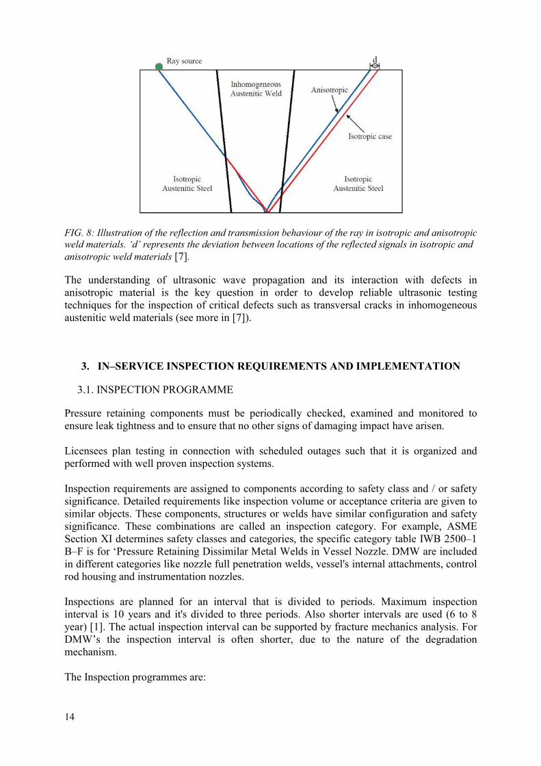
Based on the basic geometric principles in homogeneous isotropic material the defect response is easily calculated whereas in anisotropic austenitic welds geometric laws are not valid due to inhomogeneous anisotropic columnar grain structure leading to complicated defect response (for example see Figure 8) [7].
14
FIG. 8: Illustration of the reflection and transmission behaviour of the ray in isotropic and anisotropic weld materials. ‘d’ represents the deviation between locations of the reflected signals in isotropic and anisotropic weld materials [7].
The understanding of ultrasonic wave propagation and its interaction with defects in anisotropic material is the key question in order to develop reliable ultrasonic testing techniques for the inspection of critical defects such as transversal cracks in inhomogeneous austenitic weld materials (see more in [7]).
3. IN–SERVICE INSPECTION REQUIREMENTS AND IMPLEMENTATION
3.1. INSPECTION PROGRAMME
Pressure retaining components must be periodically checked, examined and monitored to ensure leak tightness and to ensure that no other signs of damaging impact have arisen. Licensees plan testing in connection with scheduled outages such that it is organized and performed with well proven inspection systems. Inspection requirements are assigned to components according to safety class and / or safety significance. Detailed requirements like inspection volume or acceptance criteria are given to similar objects. These components, structures or welds have similar configuration and safety significance. These combinations are called an inspection category. For example, ASME Section XI determines safety classes and categories, the specific category table IWB 2500–1 B–F is for ‘Pressure Retaining Dissimilar Metal Welds in Vessel Nozzle. DMW are included in different categories like nozzle full penetration welds, vessel's internal attachments, control rod housing and instrumentation nozzles. Inspections are planned for an interval that is divided to periods. Maximum inspection interval is 10 years and it's divided to three periods. Also shorter intervals are used (6 to 8 year) [1]. The actual inspection interval can be supported by fracture mechanics analysis. For DMW’s the inspection interval is often shorter, due to the nature of the degradation mechanism. The Inspection programmes are:

15
1. Pre–service inspection programme (PSI); 2. In–service inspection programme (ISI); 3. ISI programme for each outage. Baseline data should be collected for future reference. These data are normally collected in the pre–service Inspection carried out before the start of plant operation; they give information on initial conditions which supplements manufacturing and construction data in providing a basis for comparison with the data from subsequent examinations. In the Pre–Service Inspection the same methods, techniques and types of equipment should be used as those which are planned to be used for in–service inspections. Whenever an SSC has been repaired or replaced, a pre–service inspection should be performed before putting it into operation [13].
Pre–service inspections (PSI) are done to provide basic comparative information for the in–service inspection. Items that are included in up–coming ISI programme are included in PSI programme. For different safety classes requirements might vary. For example, ASME Section XI requires mainly 100% inspection for safety class (SC) 1 welds with some exemption. Data is needed to gather information about the original condition of the components in the scope of ISI. Information about manufacturing defects is needed to enable the evaluation of service induce defects. PSI is essential data when analysing DMW inspection results due their complexity. The same inspection methods and techniques, like in planned ISI, should be used to ensure reliable data. Thus, inspection techniques are not comparable to the inspection performed during manufacturing but those give supplementary information of the final condition of the component before operation. Both manufacturing and PSI is needed before operation. PSI is done before commissioning of new units or before start up after repair.
It is important to understand that there is a difference between the examination by the vendor and pre-service inspection. The examination by the vendor is according to construction code, for example, ASME Section III [1] and before the item be installed in its place. The PSI is according to ISI code, for example ASME Section XI and the examination is performed after the item is installed in its place [1].
Over the plant’s operating lifetime, the operating organization should examine SSCs for possible deterioration to determine whether they are acceptable for continued safe operation or whether remedial measures should be taken. Emphasis should be placed on examination of the pressure boundaries of the primary and secondary coolant systems, because of their importance to safety and the potentially severe consequences of their failure [13].
In–service programmes are done as required by the regulator. Typically, those are determined by inspection items per category. For example Finnish, requirements state that ‘The plan for principles of in–service inspections shall be drawn up in a manner where it covers all components and structures in safety classes 1 and 2 as well as others considered important to nuclear safety, such as pressure vessels, pumps, piping, valves and their supports, reactor pressure vessel internals, the flywheels of main coolant pumps, and the inspection areas of piping that have been selected in a risk–informed manner‘ [14]. These programmes are reviewed and updated according operating experiences and reworked when a new inspection interval starts.

16
ISI programmes for each outage are done such that the requirements of each category in the relevant interval and period are met. Maintenance programmes might influence when a specific inspection is done within a specific period.
When flaws are found and after component analyses are accepted for continued service, inspection programmes should be reanalyzed. The areas containing flaws should be re-examined subsequently to confirm possible crack growth rate. If a component doesn't need repair or replacement after three consecutive inspections at different outages then the relevant inspection programme is re-evaluated. It might be shown that an indication can be from a welding defect like root undercut and not service induced SCC. Indications resulting from welding defects do not increase SCC risks that result from in–service / environmental conditions. Actions should be designed and implemented in a manner to ensure the integrity and operability of the systems, structures and components during the next interval and finally through components service life [1].
To be commissioned, mechanical components are designed, manufactured, installed and inspected to maintain safety in connection with all events up to and including the event class ‘unlikely events’.
A component in which damage occurred is typically permitted to remain in operation without repair or replacement when it has been demonstrated that sufficient safety margins are in place against fracture, leakage and other deficiencies that could have an impact on safety during the intended period of operation.
Dissimilar metal welds typically join two or more different materials, and mostly involve Inconel Alloys in PWRs with exception of WWER type LWRs where there is no Inconel Alloy except in SCC sensitive material of the first layer of buttering. These types of welds can be found as well in PWR and BWR plants, and often connect equipment (RPV, SG, Pressurizer,…) to the main coolant piping. Dissimilar metal welds are very challenging configurations for UT examination due to the various propagation issues in austenitic structures, the presence of multiple acoustic interfaces and the complex geometry (nozzles, tapering, weld surface condition, one side access and weld crown). The presence of equipment nozzle to piping welds, tapering due to different equipment to piping thicknesses, one side access due to equipment nozzle to pipe welds with not regularly grounded weld crowns are reasons DMWs are difficult to examine, are equipped with weld overlays to make them easier to examine or are repaired or replaced by other technical solutions or DMWs.
3.2.IN–SERVICE INSPECTION PROGRAMMES REVIEW AND UP–TO–DATE
Previous inspection results, feedback from qualification, operating experience from other units and / or fracture analyzes might impact inspection programmes. Inspection programmes must be evaluated periodically to ensure, for example, optimized inspection timing. In–service inspection programmes should be continuously kept up–to–date. Updates should be done according code and standards, taking regulatory / authority requirements in account. Surveillance of inspection programme should be done annually to confirm the fulfilment of the original interval programme.
Stress corrosion cracking in DMW typically manifests itself as physical degradation in mechanical components. Major failures, repair or replacement, and modification work should
17
be analyzed. Assessment of operability and ageing–induced degradation related to relevant safety margins should follow also within an aging management programme.
Typical reasons for modification of the inspection programme include:
Changes in requirements, standards or risk analyses; Detected defects in similar structures in current unit or equivalent unit; Failure potential reduced due repair or replacement activity; Crack growth rate potential reduced; Feedback from qualification that inspection techniques is improved so that defects
can be detected earlier; and Inspection and operating experience.
When increased risk of failure is detected, inspection programme should be revised according fracture mechanism analyses. Respectively, inspection interval and periods can be often extended if risk of failure is removed after that. Before making changes in an inspection and surveillance programme after repair, feasibility of repair method for operation condition should be analyzed. Qualified inspection techniques are used to determine integrity typically after one or two years of operation. This measurement is done to support analyzes and to confirm integrity. Repaired areas should be included to inspection programme as defined in requirements or standards. The target for qualification of inspection is to give reliable and traceable information of inspections. Any feedback from inspections should be analyzed and qualifications modified accordingly. Especially, when inspecting DMW, inspection technique should be assessed when feedback from sizing real flaws are done. For example, signal to noise ratio in ultrasonic can vary from qualification coupons and the technique should be improved. If there is a hint of under sizing then the programme must be modified to ensure that defects are detected early enough. After repair activities, the inspection volume should also be analyzed. Extension of welds should include in the inspection volume. Overlay welds might reduce the inspection volume in base material. A typical requirement is the overlay weld plus 25% of base material when the overlay is pressure retaining. Authorities might have requirements to make previous defects sizing in base material. The inspection might be challenging due to compression stresses and accessibility.
When DMW's has been in reduced inspection programme and repaired successfully, extended inspection programme can be reconsidered after repair. A new inspection concept needs to be integrated into the maintenance and inspection programme. Integration might have possibility for significant cost savings when for example inspections are compound to same frequency.
3.3.RECOMMENDED INPUT PARAMETERS FOR INSPECTIONS
In order to create good prerequisite requirements for the Vendor and Inspection Qualification Body (IQB), reliable and correct data about the test object is required. This data comprises both basic information from the inspection documentation, as well as a series of different object–specific details and working environment factors. These jointly make-up the object description.
It is Licensee’s responsibility to ensure that the necessary information is produced. In order to facilitate the production of inspection objectives, information can be summarized in an

18
Inspection Datasheet, which forms the input information for inspection vendors and qualification bodies, see Annex 1.
The Licensee releases the draft Inspection Datasheet for comment by the IQB and any other relevant involved parties, to get consensus that the requirement is properly described.
The following section provides guidance as to what should be included as the minimum content.
In defining the content and format of an inspection data sheet, there are several key points:
A full description of the component to be tested including material, surface finish and access;
Type, dimension, orientation and location of defects to be detected and / or sized, depending on the defect situation considered;
The inspection performance (detection, characterization, sizing and location) to be achieved;
Non–Destructive Testing (NDT) procedure, equipment and personnel requirements; and
Environmental consideration if applicable.
Inspection datasheet of inspection requirements:
A unique identifier — Each Inspection Datasheet should be given a unique identifier taken from a recognized reference system.
Name of Component / Code Item — This should be unambiguous and be self–explanatory — nozzle attachment weld, thermal shield support ledge, system identification etc.
Type of Inspection — Pre–service or in–service inspection.
Scope — The full range of component geometries, dimensions and materials to which the Inspection Data Sheet applies.
Component material and geometry — Manufacturing / Welding Details / Appropriate Drawings–A list of the drawings and information that indicate the geometry, materials and fabrication process of the component that is relevant to the inspection. This information should also provide a clear indication of the space envelopes available around the inspection area for access–this is particularly important for ISI.
Component material and geometry — Parent / Welding / Buttering Material–The types of material used to fabricate the component including parent materials and welding consumables. This information is very important and has a significant impact on inspection system design.
Weld crown configuration — Specify if weld crown is grinded planar to base material or not.
Welding processes
Component material and geometry — Surface Form and Roughness — The surface morphology of the inspection surface can have a significant influence on achievable inspection performance. Ideally quantitative statements should be given (e.g. 3.2μm
19
Ra for a good machined surface finish) and an indication as to how the final surface was fabricated (i.e. machined, hand ground, as–welded etc.)
Historical information — Information and results from previous performed inspections on the actual object.
Defect Description — Nature of Defect — Brief description of the type and location of defects. For instance:
(i) For fabrication inspection — lack of fusion, slag inclusion or underclad cracking defects. Those are in most cases embedded flaws;
(ii) For in–service inspection (ISI) — thermal fatigue or mechanical fatigue and SCC are some of the types that may be expected. Those are in most cases surface breaking.
Defects description — Orientation — The possible orientations of the defect(s) should be indicated. This is conventionally specified via “circumferential”, “axial”, ‘tilt’ and ‘skew’ ranges relative to a reference plane.
Defect description — Crack Opening Displacement COD — An indication of the distance between the crack faces. It depends on crack type, material and location.
Defect description — Roughness — This refers to the roughness of the defect faces, which can have a significant impact on ultrasonic inspection capability. It depends on crack type, material and location and further information can be found in “Wåle J., Crack characterisation for in–service inspection planning [15].
Defect description — Qualification Defect Size — In many cases the qualification defect size, depth, length and width, will be defined via a structural analysis and fracture mechanic calculation. For instance, crack width is important for visual inspection techniques. It can be done for respectively object and situation or values can be taken from a Code and Standard.
Sizing / Locational accuracy — required tolerances on the reported size, both length and height, and position of the defect. Value of ligament of embedded flaws and tolerances of ligament measurement should be defined.
Examination volume — The region within which detection and sizing of the defects is required.
Defect specification — An as–built drawing of open test block showing the inspection volume, geometry of the component, position and orientation of defects, defects tilt and skew should be included.
Notes — Any other relevant information as human– and environmental factors.
3.4.INSPECTION TECHNIQUES
Nickel–based alloy cracking of reactor pressure boundary components has been a worldwide concern for about 25 years. Increased inspection frequencies, improved inspection practices, and increased licensee vigilance continue to identify nickel–based alloy cracking in vessel penetrations and various components of the primary coolant loop. To address the issue of

20
quantifying the effectiveness of Non–Destructive Examination (NDE), many international Round Robin Tests (RRT) have been conducted since 1986.
The most common NDE techniques for inspections on DMW’s are Ultrasonic (UT) and Eddy Current (ECT). The use of ECT prerequisite inspection from the inner surface of component, i.e. from the surface where cracks are propagating. When inspections are performed from the outer surface, UT is the method that is normally used.
All inspections on the inner diameter (ID) are done as mechanized inspections, i.e. encoded systems, but outer diameter (OD) inspections could be done as both manual (non–encoded) or mechanized.
UT is a volumetric inspection method as Radiographic testing (RT), but of different circumstances like of height sizing of cracks and accessibility, the RT is not a technique to be recommended.
For UT there are several different approaches like conventional pulse-echo, phased–array probes (PAUT), and time–of–flight diffraction (TOFD) technique.
Below are a few conclusions from different international studies about those techniques and to get the most reliable inspection result.
The use of a diversity of techniques (UT, PAUT, TOFDT and ECT)–tended to improve performance for detection, depth–, and length sizing.
The advances in the use and deployment of Phased Array Ultrasonic Testing (PAUT) is significant and procedures including this technology tended to perform better than those relying on conventional UT using one or only a few inspection angles.
Having access to the ID surface from which Primary Water Stress Corrosion Cracking (PWSCC) initiates for complex Dissimilar Metal Welding (DMW) configurations, is preferred.
There was a wide variety of scatter in the performance data thus, all three studies recommend the need for procedure, equipment and personnel qualification.
DMWs are very complex because of geometry and metallurgy, making them one of the most challenging nuclear power plant components that need to be reliably inspected during in–service inspection.
Length sizing accuracy appears to support the needed level of performance required by the current code and standards particularly when PWSCC initiation surface is available for inspection.
Correct flaw manufacturing techniques in test assemblies for performance demonstrations are important to get a realistic signal response compared with a real SCC.
For individual NDE inspection methods and NDE techniques there are different surface conditions and accessibility requirements given in inspection procedures.
Manually driven or encoded examinations of DMWs produce data acquisition files with ultrasonic data. Qualified data analysts using an encoded UT inspection procedure determine the presence of in–service flaw indication caused by in–service degradation in the examined

21
component with the DMW. The DMW data files can be re-evaluated by multiple analysts either during the examination or more usually later with a possibility to compare data files against data from a subsequent examination.
3.5.INSPECTION QUALIFICATION
3.5.1. Background
The objective of this section is limited to a general guideline on how inspection qualification for DMW’s should be carried out. The decision on whether an inspection should be qualified is a matter for agreement between the parties involved or it is requirement of the Regulatory Body. The NDE qualification will not be required for all routine NDT inspections. Qualification should be considered where the safety or economic consequences of possibly poor NDT performance, and / or the difficulty of applying the NDT, are such that additional assurance is desirable that the NDT can meet the requirements. Qualification should also be considered when a novel NDT technique is proposed for DMW inspection. In such a case the inspection procedure for a novel NDT technique and the technical justification should contain specific analysis of essential variables derived from the inspection procedure for flaw distribution based on degradation mechanisms, inspection procedure search units applied parameters analysis and the component description described in technical specification.
Inspection Qualification or Performance Demonstration, by definition, is a process of systematic and independent assessment, by all those methods that are needed to provide reliable confirmation, of specific non-destructive examination (NDE) system to ensure it can achieve the required performance under real inspection conditions.
Reliable results of non–destructive examinations in nuclear power industry are of outmost importance and fundamental for the safe operation of any nuclear power plant, therefore a failure to detect a flaw that may threaten nuclear power plant’s primary circuit integrity or to declare flaw detection in an unflawed component of nuclear power plant is undesirable. Through the process of qualification (performance demonstration) an assessment of the capabilities and limitations of NDE systems is performed. An objective of qualification is to ensure that the detection, characterization and sizing of flaws are reliably achieved throughout components of nuclear power plants, hence resulting in effective NDE that contributes to the overall ISI effectiveness.
Two main qualification methodologies for performance of inspection qualification exist, ASME / PDI and ENIQ. A third approach, which was primarily developed for WWER nuclear power plants is the IAEA methodology which combines the ENIQ and ASME approaches.
Therefore, the qualification scope of a NDE system consists of three main elements:
The qualification of equipment which are used for the examination;
The qualification of personnel who performs the examination; and
The qualification of procedure that instructs how to perform the examination.

22
3.5.2. Qualification of equipment
Equipment, as per ASME Section XI Appendix VIII approach [1], is qualified together with the procedure through the blind trials. Equipment essential parameters with allowable values and tolerances are identified within the procedure, and verified/measured, as appropriate, during the practical demonstration.
Within the ENIQ methodology [16], equipment (manipulator) can be qualified together with the procedure on the open demonstration or be qualified separately on an object specific mock–up. If equipment is qualified by itself, a technical justification is presented for review by the QB, together with a practical demonstration on a mock–up. A certificate is valid as long as no modification has been done to the equipment.
3.5.3. Qualification of NDE procedure
The purpose of an Inspection Procedure, written by vendor, is to be an important instruction for inspectors when performing the inspection in plant. Therefore, the procedure shall be written in an unambiguous way, which means that different inspectors will do the same and come to similar result when they follow the procedure, i.e. a clear instruction describing what and how to perform the inspection and not why.
The qualification for instance within the European Network for Inspection and Qualification (ENIQ) [16] is to demonstrate the inspection procedure step–by–step on open test pieces, and to be approved, if all included flaws have to be detected, characterized and sized within stipulated criteria and tolerances.
The certificate is valid unless there are changes to the technique.
Procedure qualification as per ASME Section XI Appendix VIII [1] approach includes at least three personnel performance demonstration test sets from the blind trials. Appendix VIII listing the essential variables whose value must be specified in the inspection procedure to ensure, that there are no unspecified variables which could cause the performance to vary from that established by qualification. Successful qualification of procedure is required by demonstration the detectability of required number within its scope. At least one successful personnel qualification should be performed and successful personnel qualification might be combined to satisfy requirements for procedure qualification.
The procedures should have clear criteria for analysis and reporting of detected flaws and define the responsibilities for resolution and disposition of all flaws reported.
There are two basic elements included in an inspection qualification for dissimilar metal welds: Technical Justification and Practical trials. Of practical reasons test piece trials often provide only limited information on the performance of an NDT system, due to a limit number of flaws.
The purposes of the technical justification (ENIQ) are:
1. To overcome these limitations by citing all the evidence which supports an assessment of the capability of the NDT system to perform to the required level; it follows that a better defined confidence in the inspection is provided.
23
2. To complement and to generalize any practical trials results by demonstrating that the results obtained on the specific defects in the test pieces would equally well have been obtained for any other of the possible defects.
3. To provide a sound technical basis for designing efficient test piece trials.
4. To provide a technical basis for the selection of the essential parameters of the NDT system and their valid range.
5. Technical justification includes a written statement of the evidence which supports the case that an inspection can meet its requirements. It comprises a mixture of experimental evidence and theoretical assessment as appropriate. The ENIQ technical justification typically includes:
A technical justification may be structured in accordance with the ENIQ RP 2 [3]:
1. Summary;
2. Section 1: Introduction;
3. Section 2: Summary of Relevant Input Information;
4. Section 3: Overview of Inspection System 6;
5. Section 4: Analysis of the Influential and Essential Parameters;
6. Section 5: Physical Reasoning (Qualitative Assessment);
7. Section 6: Prediction by Modelling (Quantitative Assessment);
8. Section 7: Experimental Evidence;
9. Section 8: Parametric studies;
10. Section 9: Equipment, Data Analysis and Personnel Requirements 8;
11. Section 10: Review of Evidence Presented;
12. Section 11: Conclusions and Recommendations, and
13. References.
6. Sometimes theoretical assessment is needed to relate experimental evidence from similar inspections to the actual situation. Theoretical assessment can also provide independent evidence on the adequacy of the proposed inspection.
7. A more quantitative approach to theoretical assessment involves the use of mathematical models of the inspection where these are available. Care should be taken in using such models to ensure that they have been validated under the conditions of the particular inspection. Models can be particularly valuable in being able to extrapolate and interpolate practical inspection results gained under one set of conditions to others. In doing this, they enable specific practical results to be generalized. They can also allow results gained on test pieces to be extended to the real component thereby permitting the use of simple test pieces. Further guidance on the use of mathematical models can be found in ENIQ Recommended Practice 6 [17].
8. All possible parameters of the equipment, the defects and the component which might have an influence on the outcome of the inspection are called influential parameters. In general, of all the possible influential parameters, only a limited number, the essential parameters, will indeed have a significant influence on the inspection

24
outcome. These essential parameters should be identified and the range in which they can vary should be defined. For the defects and the component, the essential parameters are defined in the input information to be provided prior to inspection qualification and the qualification is only valid within the defined boundaries. For the NDT equipment and procedure, it should be verified during qualification that requirements are included (e.g. calibration requirements) which ensure that the essential parameters remain within the defined boundaries in order not to invalidate the qualification. Further guidance on influential and essential parameters can be found in ENIQ Recommended Practice 2 [3].
9. If practice test pieces (mock–up / open test specimens) are made available prior to the start of inspection qualification, the results obtained on them can be very useful in justifying some of the chosen inspection parameters, especially (for ultrasonic inspection) in the case of austenitic components (provided that the practice test pieces are similar in all relevant aspects to the ones used during qualification).
10. An important element of the technical justification is the feedback of field experience, mentioned above. This source of information can become the most important one if the populations of similar components or plants are large enough. This feedback has, however, to be validated. The information generated should not be biased by experts’ impressions. Evaluation, possibly involving destructive examination, is often necessary to validate the information coming from plant inspections.
11. If the process of assembling the evidence for the technical justification reveals any shortcomings in the capability of the inspection, as compared to the desired performance, these shortcomings should be clearly stated both in the text of the technical justification and in its conclusions.
3.5.4. Modelling
The purpose of modelling is to generate quantitative and qualitative predictions about aspects of inspection performance using mathematical models of the physical phenomena on which the NDT technique under consideration is based. Normally the mathematical model is implemented as a computational model although some mathematical models may be amenable to hand calculation using simple mathematical formulae or implementation in spreadsheets. In the following the focus is on the computational models and corresponding software codes, which will be referred to as “models” and “codes”.
Modelling can be an attractive option for generating evidence on inspection capability for technical justifications. It has four key advantages over the alternative approach of performing experiments on test specimens: speed, cost, versatility and invariance of experimental error.
The speed and cost advantages are clear. Running a model is generally much quicker and more cost efficient than manufacturing and inspecting test specimens. This is especially true if realistic defects are required in the test specimens, rather than simple reflectors such as notches or flat-bottomed holes, provided the model is able to handle realistic defects.
The third advantage is that of versatility. A good model should be able to handle a wide range of inspection parameters and possible defect positions, shapes, sizes and orientations. A test specimen, by contrast, can only include a limited number of defects, and it will not normally be possible to cover the full range of plausible defects, as defined in Input Parameter Specification [5]. A good model can fill the gaps in the experimental results and reduce the

25
number of test specimens needed. Provided they remain within their regimes of validity, models can also be used to extrapolate experimental data over the full range of essential parameters and so generalize experimental data.
The last advantage — the results from modelling do not include inherent variation due to experimental error or environmental influence as would be encountered with test piece trials. Sources of errors such as uncertainty in defect size and shape are also not encountered, and sources of error unique to modelling (e.g. numerical error) are typically much smaller.
Despite these advantages, modelling is rarely used alone to provide evidence for a technical justification. More usually it provides one element of evidence, alongside other sources (e.g. experimental evidence, parametric studies, physical reasoning, feedback from field experience, equipment considerations) [17].
3.5.5. Test pieces in practical demonstrations
Before a test piece is used in qualifications it has to undergo a quality assurance inspection. It means that flaw locations, orientations, sizes and signal responses must be checked with an appropriate inspection technique. Normally this is done by the qualification body, and always when blind test pieces shall be used.
Practical trials may involve test pieces replicating the component being inspected in size and geometry. The defective condition may also be accurately replicated. If metallurgical flaws are involved, the test piece will be designed to contain flaws of the type judged to be possible in appropriate positions and will normally include the “worst case” defects defined as those most difficult to detect, characterize and size for the given inspection situation. Also, the most likely — and the highest safety consequence defects are included.
Such test pieces will produce realistic result but are expensive to manufacture and can usually only replicate a small fraction of the flaws which might occur.
Test pieces are essential for open and blind trials of qualification process, together with the technical justification. Open trial is a practical demonstration in which the inspection personnel is previously informed on the type, number and characteristics of the test pieces as well as on the type, morphology, position and dimensions of the flaws to be detected and sized.
For example, both ASME and ENIQ approach relies highly on performance demonstration by using full–scale test pieces. The design of test pieces is based on the information taken from the Technical specification, i.e. the input parameters for inspection.
3.5.6. Qualification of NDE personnel
In the context of the ENIQ and ASME methodology, personnel qualification is defined as the process that demonstrates that personnel are capable of implementing a specific qualified inspection or inspections.
Certification is defined as the process that demonstrates personnel have the basic skills to implement an inspection method and may not refer to specific procedures. Usually, member countries will have their own certification schemes that meet some recognized standard such as ISO 9712 [18] or ANSI / ASNT CP189 [19]. Complementary certificates can be

26
implemented by independent organization / qualification body for nuclear application that are specified to specific procedure for DMW.
The ENIQ Recommended Practice RP10 [20] “provides recommendations for the qualification of inspection personnel where this is required. The recommended practice does not give guidance of when personnel qualification should be performed — this is an issue to be agreed with the relevant organizations”.
“The recommended practice RP10 [20] is relevant to any non–destructive testing method. It is emphasized that the general principles given in this recommended practice can also be used for qualification of manufacturing inspections.
The principal objective of personnel qualification is to ensure that those carrying out an inspection are appropriately trained, experienced and examined to ensure it is applied correctly and effectively. Automated inspections usually involve several stages which may be performed by different personnel: for example, manipulator operators, and data collectors and data analysts. It may be necessary to qualify some or all the personnel undertaking these roles in different ways to demonstrate that they are capable of performing the tasks required of them. Specifically, for automated inspections, it may only be necessary to qualify the data analysts as there may be sufficient checks on the data that an incorrectly mounted manipulator will be clear from the data quality and therefore there is no need to qualify the manipulator operators.
It is necessary, when an inspection procedure is developed, to determine the requirements which the personnel who will carry out the inspection should meet. These should be clearly defined and will be determined by several factors:
Whether the inspection is manual or automated and the different roles fulfilled by different groups of personnel in the latter case;
If the inspection is a manual one, whether the inspection imposes technical demands beyond those examined through a national certification scheme such as those discussed above; and
If the inspection is automated, whether it has features which require particular skills beyond those normal for automated inspections” [20].
In the ENIQ methodology personnel qualification is done through one or any combination of the following:
Theoretical and / or open practical examination; or Blind trials.
In some cases, are personnel approved through a national NDT personnel certification scheme, but this is not the same as qualification on an object specific inspection procedure.
Qualification of personnel as per ASME Section XI Appendix VIII approach, for both manual and automated examinations, is exclusively through the blind trials and only for the data analysis personnel. An initial requirement for personnel qualification is that candidate is certified to at least Level II through a national NDE certification scheme, i.e. ISO 9712:2012 [18]. Successful personnel qualification might be combined to satisfy requirements for procedure qualification. Other personnel (data operators / acquisition, supporting personnel,

27
etc.) requirements including their training requirements are specified in the examination procedure. Qualification of personnel for manual examinations is performed using generic qualified procedures and equipment. Criteria for successful personnel qualification with regards to detection and false calls, location tolerance, length and depth sizing are given in respective Supplements of Appendix VIII or another qualification requirement.
The IAEA methodology for qualification [21] is based on very similar principles as the ENIQ methodology [22]. The main differences are in the additional personnel qualification requirements. In the IAEA methodology is personnel qualified after the qualification of inspection procedure and equipment through practical trials under "blind" conditions. Other not negligible differences are for example in the role of the Regulatory Body as there is required the approval and periodical audits of the quality system of the Qualification Body, review and approval of qualification protocols, review and comments on qualification procedures.
Especially for high majority of the manual ultrasonic examinations of DMWs cannot be generally recommended to consider personnel certification as sufficient without additional personnel qualification using the appropriate qualified inspection procedure.
3.6.EVALUATION OF INSPECTION RESULTS
3.6.1. Background information and introduction
The character of SCC is changing from small multiple cracks to one or several branched SCC propagated from the marginal defect. The focus on DMWs and occurrence of specific degradation mechanisms after more than 30 years of operation in relation to extended lifetime assessment of appropriate components and piping systems with these welds has been initiated and supported by DMW SCC latest issues in the world (5 axial PWSCC at North Anna or circumferential SCC on WWER–440 type SG collector DMWs in Russia and Ukraine) and Regulatory Body requirements on provided License Renewal documentation related to the lifetime extension.
The knowledge of at least the following details of manufacturing and inspection history of DMWs is important for successful evaluation of DMW NDE examination:
Surface condition; Welding process details from the weld drawing (as weld bevel angle, weld crown
and weld root dimensions, counterbore, etc.); Weld accessibility.
Similarly, the evaluation of data quality for encoded examinations should be considered during outage as follows:
The utility should schedule the work process of DMW NDE examinations accordingly and be prepared for the necessity of rescans. The impact of rescans can be minimized by requiring review and approval of the DMW data quality by a qualified analyst before authorizing the acquisition team to move to the next component. If the examination schedule will not facilitate completion of data review before moving to the next component, the weld should remain readily accessible (for example, insulation still removed and scaffold still up) until the data review is completed.

28
Degradation initiation rate; and Degradation growth rate.
Both height and length can be determined by analytical evaluation of allowable flaw height (depth) and length calculation according to appropriate standard as ASME code Section XI [1].
The approach of ASME, 2013 Section XI was applied for evaluation of allowable flaw sizes in the WWER–440 type primary collector DMWs [1]. The ASME SCC growth rate curves were verified by the tests performed in UJV Rez autoclaves to be applicable on WWER–440. Allowable flaw sizes and partially verified SCC growth curves provide better planning of weld repair time schedule. Flaws of depth app. 25 % are not rare in many WWER–440 Units. From the results can be seen that maximum ISI allowable crack can be reached after 26 months and the critical crack after one more year. For fully justifiable conclusions, more autoclave tests are needed as only limited number of tests was performed within the verification process. Moreover, verification of ASME XI [1] factors for WWER steels should be performed as well.
Inspection interval;
Inspection interval is usually determined according to applicable standard.
Probability of degradation detection as a function of degradation type, size, location, etc.
POD curves can be determined based on the blind RRT or blind UT qualification tests performed on test pieces with intended defects or using UT inspection simulation software verified by experimental trials. In the majority of cases the numbers of blind RRT results or blind UT qualification tests are not sufficient.
Accuracy of degradation sizing as a function of degradation type, size, location, etc. to ensure that the proper corrective action can be taken.
After an indication is reported by NDE during ISI, it has to be evaluated to determine if it is a relevant flaw which can be treated as a defect. The extent or size of a defect is to be characterized in accordance with regulatory code if application, e.g. ASME XI IWA–3300 [1]. The flaw should then be evaluated in accordance with relevant code or standard (e.g. ASME XI IWB–3500) if it is acceptable with no further action. When the defect exceeds the size of allowable size in an acceptance standard, the defect can further evaluated analytically as recommended by the code to calculate its growth until the next inspection or the end of service lifetime of the component, e.g. ASME XI IWA–3600 [1]. If the flaw is found to be non–acceptable for fit for service, the flaw will be treated as a defect which warrant repair. Figure 9 illustrates the process of flaw evaluation in accordance with ASME XI [1].
The flow chart for evaluation of the inspection results, the evaluation process may proceed as follows [14]:

29
FIG. 9. Flow chart evaluation of the inspection results [14].
End of operation period and start of outage.
1. In–service inspections are performed and indications exceeding the recording level are recorded, the flow chart for evaluation of in–service inspection results apply.
2. Indications exceeding the recording level are characterized and it is investigated whether they are geometrical or from a flaw.
3. The flaw is compared against the results of previous in–service inspections, and it is investigated whether the flaw is new or whether it has grown.
4. If the flaw has been characterized as a macroscopic imperfection and exceeds the acceptance standard, it should be defined as a defect and be part of further analysis like sizing

30
5. The type, location and size of a new or grown defect are characterized by applicable characterization technique.
6. A risk analysis is applied on any defect larger than the limits specified in the acceptance standard and the cause of the flaw is assessed.
7. After the cause of the defect is assessed and a risk analysis applied it is decided whether the defect is allowed in the structure.
8. If the defect is allowed in the structure, measures are taken to eliminate causes of the defect and to prevent and monitor growth.
9. If the defect is not allowed in the structure, the area is repaired or replaced and pre–service inspections are conducted. The causes of the defect are eliminated and the need for further measures assessed.
10. A decision is made about the structure’s fitness for its purpose [13].
Follow-up of these additional measures are strongly recommended for the evaluation of inspection results:
a) Extend inspection to similar material, structures in environment; b) Repair or replacement when defect is not allowed in structure; c) Update inspection programme if flaw or defect is accepted to structure; d) Re-examination in next outage to confirm analyzed crack growth, and e) Maintain or development of repair techniques.
Exclusion of causes and the measures to monitor structure could include e.g.:
Restrictions or alterations to operating conditions; Continuous flaw monitoring; Structural modifications such as weld overlays or modifications of supports, and Additional inspections and reduction of inspection interval.
3.6.2. Acceptance standards and methods
The basic requirement level of in–service inspections (ISI) is determined in codes and standards. Deviations should be justified. Supplementary guidelines are provided in the International Atomic Energy Agency’s guide document IAEA Safety Standards Series No. NS-G-2.6, Maintenance, Surveillance and In–service Inspection in Nuclear Power Plants [13].
Inspection target defect size shall be primarily based on defects allowed during the nuclear facility’s operation by the standard applied in the design of the component or structure in question. Acceptance standards are supported with specific fracture mechanical analyses that has made to the structure before inspection. These can be done for example accordance with the acceptance criteria of ASME Code, Section XI Subarticle IWB–3600, or some other procedure separately approved by authority. Calculations which have been done before inspection support efficient decision making. Urgent repair needs are identified immediately.

31
3.6.3. Exceeding threshold set in acceptance standards
If defects are found and analyzed size exceeds the threshold that is specified in the acceptance standard, further actions should be done. Flaw should be sized with qualified techniques to provide correct information for analyzes. Inspection techniques qualifications should be analyzed to confirm reliability of the inspection result. If needed further inspection should be done with another qualified technique or method.
When the flaw is confirmed and sized following actions should be done:
An assessment of the mechanisms affecting flaw (root cause analysis) should be always presented;
Safety analysis (PRA); Fracture mechanical analyses; Structure replacements or repairs if needed; The inspections are extended to cover equivalent areas, as required in specifications;
and Modifications to inspection programmes.
Safety analysis of component or piping system with the flaw takes into account calculated potential consequences for the component or piping system using probabilistic safety methods.
If the flaws are to be approved to remain in the structure based on fracture mechanical analyses and without repairs or replacements made to the structure, tightened inspection intervals and special measures to prevent and monitor flaw growth, is needed. Also, evaluation of qualification of inspection technique is needed. When inspecting DMW's, the possibility of under sizing should be evaluated.
Typical reasons for under–sizing flaws in DMWs are:
Inspection technique is not qualified; Inspection technique is qualified for sizing only for inspection volume in DMW's
which is typically 1/3 of thickness; Ultrasonic inspection frequency is too low for measurement of tight cracks height in
DMWs; Ultrasonic inspection frequency is too high compared to sound path and it can't
propagate to DMW material to make sizing correctly; and Sizing with ultrasonic is done with too long sound beam related to DMW (wrong
side of pipe OD / ID; see previous point).
The fitness for service (FFS) assessment results can yield, for example, the required minimum fracture toughness for a given loading conditions and postulated defect size or can provide maximum tolerable defect size (e.g., weld imperfection) for a given material, loading conditions and fabrication route.
The FFS assessment modules require, in general, for the components in–service the following interdisciplinary inputs:
Description/knowledge (mechanism) of damage; Determination of operating conditions, load/stress analysis;
32
Flaw characterization (location, sizing via NDE), and Material properties (incl. environmental effects).
There are no such standards or procedures for multi–metallic components or specimens that are made up of different material sections joined together via a weld. Number of different level options of analysis available to the user, each being dependent on the quality and detail of the material's property data available as it is well described in the FITNET Fitness–for–service procedure section 6 [23] for instance. Some of them requires advanced numerical modelling and offer sophisticated results, but detailed material information and high level experts needed to carry out the analysis. Other methods can be applied with less detailed material data but higher safety margin has to be set due to the lower quality of the results. So called engineering assessment methods allow evaluation of cracked structures without the need to conduct detailed FE analyses, based on analytical equations. For FFS assessment particularly versatile method is R6 R/H/R6-Revision 4 [24], 1995 or BS 7910, 2013 [25] which is based upon the use of failure assessment diagram (FAD) [25]
3.6.4. Fracture mechanical analyses
The complexity of the problem results from the prevailing mixed–mode loading conditions, the variation in material constitutive equations across the weld zone, and the presence of large residual stress fields. Under these circumstances, classic fracture mechanics concepts are difficult to apply. The analysis work requires extensive materials characterization around the fusion line: strength, ductility and fracture behaviour of the weld heat affected zones (HAZs) and the dissimilar parent metals. JIC–values and fracture resistance (R) curves, characterizing the fracture initiation toughness and ductile crack growth, respectively, are required as inputs to the structural integrity analyses.
Three basic methodologies can be followed: conventional flaw assessment methods, more advanced J methods and Local Approach methods.
The major conclusions of the methodologies are the following:
Finite element analyses can successfully model the macroscopic deformation and fracture behaviour.
The analysis could predict the load at initiation of ductile tearing accurately, but the prediction was critically dependent on the degree of representation of the resistance curve derived from the small–scale fracture test to that of the full–size test pipe in term of crack sharpness, material microstructure, and constraint.
The analysis successfully predicts the narrow range of load over which significant growth of the defect occurred, a consequence of the low tearing resistance of the buttering material.
The growth of the defect through the wall but without change in circumferential extent can be predicted from the analysis results. It is behaviour typical of a long-part–through–surface breaking defect in ductile material subject to a uniform tensile stress field.
The integrity assessment and life estimation for such welded structures require consideration of residual stresses. Therefore, it is necessary to map and assess the distribution of these residual stresses in welded joints. The residual stresses in similar and dissimilar metal welds
33
are generated by the thermal contraction of the weld metal and the adjacent heated parent metal, and hence the residual stress distribution in an as–welded DMW is broadly similar to that in a similar metal weld. Although information on the magnitude and distribution of welding residual stresses is available in several codes and standards, these are not validated extensively for DMWs. It is recommended that residual stresses in DMWs should be measured physically or calculated numerically by computational welding simulation.
The welding of DMW can be simulated using three–dimensional (3D) thermos–mechanical and metallurgical finite element model. Work tasks:
Simulate the cladding process; Simulate the buttering process; Simulate the heat treatment after the buttering, and Simulate the butt–weld process.
The procedure can be applied during the design, fabrication or quality control as well as operational stages of the lifetime of a structure, and also applicable to failure analysis.
In order to cover the above described cases, the fracture analysis of the component containing a crack or crack–like flaw is expected to be controlled by the following three parameters:
The fracture resistance of the material; The component and crack geometry; The applied stresses including secondary stresses such as residual stresses.
If, as is usually the case, two of these parameters are known, the third can be determined by using the relationships of fracture mechanics.
An in–service inspection interval can be specified based on the residual lifetime that an assumed initial crack given by the NDE detection limit under service conditions requires to extend to its critical size. In this case the present module will be part of a fatigue crack extension analysis. Finally, a minimum required fracture resistance of the material can be specified based on the critical crack size or the NDE detection limit under service conditions to avoid failure during the projected lifetime of the component.
Components and piping, or parts thereof, in which defects exceeding acceptance standards are detected during in–service inspections must usually be repaired or replaced.
3.6.5. Root cause analysis
Root cause analysis (RCA) is a collective term used to describe a wide range of methods and tools used to uncover the underlying or “root” causes of problems. Root causes are eliminated by identifying factors that contribute to the problem and finding solutions. RCA focuses primarily on systems and processes, not individual performance.
Every root cause investigation and reporting process should include five phases. Descriptions of this approach may be found in the root cause analysis guidance document, US DOE Guideline, DOE-NE-STD-1004-92 [26] and Root Cause Analysis Following an Event at a Nuclear Installation: Reference Manual, IAEA-TECDOC-1756 [27].

34
While there may be some overlap between phases, every effort should be made to keep them separate and distinct.
Data Collection
“It is important to begin the data collection phase of root cause analysis immediately following the occurrence identification to ensure that data are not lost. (Without compromising safety or recovery, data should be collected even during an occurrence.) The information that should be collected consists of conditions before, during, and after the occurrence; personnel involvement (including actions taken); environmental factors; and other information having relevance to the occurrence.
Application: This method is always used for any event investigation in which a timeline or sequence of events might apply regardless of the initiating event being equipment failure or human performance” [27].
The attributes of the Event and causal factor charting:
Graphically display concisely captures the entire event; Breaks down the entire case into a sequence of occurrences; Shows exact sequence of events from start to finish in a chronological order; Allows addition of barriers, conditions, secondary events, presumptions; Facilitates the integration of information gathered from different sources; Useful for both simple and complex problem solutions; Many causal factors become evident as the chart is developed; and Presents the information in a structured manner.
FIG. 10. Structure of an event and casual factor chart [27].

35
1. Assessment methods:
Change Analysis: Change Analysis is used when the problem is obscure. It is a systematic process that is generally used for a single occurrence and focuses on elements that have changed, but does not lead directly to the root cause. Figure 11 shows the six main steps involved in Change Analysis.
FIG. 11. Six steps involved in change analysis [27].
Barrier Analysis: Barrier Analysis is a systematic process that can be used to identify physical, administrative, and procedural barriers or controls that should have prevented the occurrence. Barrier analysis is based on the concept that hazards represent potentially harmful conditions from which a target (personnel, equipment and environment) must be protected.
Management oversight and Risk Tree (MORT) Analysis: MORT and Mini–MORT are used to identify inadequacies in barriers / controls, specific barrier and support functions, and management functions. It identifies specific factors relating to an occurrence and identifies the management factors that permitted these factors to exist.
Human Performance Evaluation: Human Performance Evaluation (HPE) identifies those factors that influence task performance. The focus of this analysis method is on operability, work environment, and management factors. Man–machine interface studies to improve performance take precedence over disciplinary measures.
Corrective Actions:
36
Implementing effective corrective actions for each cause reduces the probability that a problem will recur and improves reliability and safety.
Inform:
Entering the report on the Occurrence Reporting and Processing System (ORPS) is part of the inform process. Also included is discussing and explaining the results of the analysis, including corrective actions, with management and personnel involved in the occurrence. In addition, consideration should be given to providing information of interest to other facilities.
Follow–up:
Includes determining the corrective action if those has been effective in resolving problems. An effectiveness review is essential to ensure that corrective actions have been implemented and are preventing recurrence.
Management involvement and adequate allocation of resources are essential to successful execution of the five root cause investigation and reporting phases.
4. REPAIR, REPLACEMENT OR MITIGATION
4.1.BACKGROUND
Pressure retaining components containing flaws, particularly unacceptable flaws, would require replacement or repair. Decision of opting for replacement depends on many factors for consideration, e.g. cost, plant remaining operating life, accessibility, lead time of acquiring the component etc. However, the replacement option has the advantages of utilizing the latest improved materials, improved dissimilar metal welds and design changes to mitigate SCC. The classic example is the replacement of steam generators containing the PWSCC–prone Inconel 600 tubes. The replacements are consisted of Inconel 690 tubing which improves resistance to PWSCC. The connection welds of the Safe Ends to the SG nozzles are comprised of 52M weld metal which has improved resistance to Inconel 82 and Inconel 182 weld metal.
The operator of Candu pressurized heavy water reactors located in Ontario, Canada, took the opportunity during the refurbishment of the units to replace flow elements with improved materials. These flow elements are consisted of orifices to measure flow. These devices are installed in some of the pipes which feed primary heavy water to the reactor fuel channels. The original material is Inconel 600 welded to carbon steel feeder pipes with Inconel 82. It has been determined that the flow element to carbon steel feeder tube weld could be vulnerable to PWSCC as seen in PWR. Noting that PWSCC is thermally activated mechanism, the cracking propensity of the flow elements is deemed to be lower because the highest operating temperature of the flow element is at about 312oC which is lower than the operating temperature (about 325oC) of PWR. The operator conservatively decided to replace these flow elements with Inconel 690. The elements are joined to pipes with 52M.
PWSCC is defined as the inter-granular or inter–dendritic cracking of nickel–base alloys that occurs in-service and originates from the surfaces of a component that are wetted by the primary water of a pressurized water reactor (PWR).

37
IDSCC (inter–dendritic stress corrosion cracking) refers to SCC in which crack growth propagates between the tree–like grains that can form in castings or weld metal.
The term PWSCC implies applicability limited to PWR–type components. The convention adopted in this publication is to refer to the target degradation as PWSCC / IDSCC because the intended focus is to address SCC that occurs in nickel alloy components exposed to light water reactor conditions, inclusive of both PWR and BWR conditions.
4.2.WELD REPAIR TECHNIQUE CONSIDERATIONS
4.2.1. PWSCC susceptible locations
Locations potentially susceptible to SCC for Westinghouse, Combustion Engineering, and Babcock & Wilcox PWRs are summarized in Table 2 [28]. A location is determined to be susceptible if Alloy 82 / 182 were used during fabrication. It should be noted that while Alloy 82 and 182 are frequently listed together the chromium content of Alloy 82 and 182 are not the same. In fact, Alloy 82 has a specification range of 18%–22% Cr and 182 has a specification range of 13%–17% Cr. [29]. Therefore, areas welded with Alloy 82 would be expected to be less susceptible to SCC compared to Alloy 182. Note that in Table 2 RCS, SG, RCP, HL, and SDC are acronyms for reactor coolant system, steam generator, reactor coolant pump, hot leg, and shutdown cooling respectively.

38
TABLE 2. EXAMPLE OF LOCATIONS INVOLVING ALLOY 82 / 182 PIPE BUTT WELDS [22].
Location Westinghouse Design Plants
Combustion Engineering
Design Plants
Babcock & Wilcox Design
Plants
Reactor Vessels
Inlet & Outlet Nozzles Yes No² No
Core Flood Nozzles N/A N/A Yes
Pressurizers
Surge Line Nozzles Yes Yes Yes
Spray Nozzles Yes Yes Yes
Safety & Relief Valve Nozzles Yes Yes Yes
RCS Piping Loop
SG Inlet & Outlet Nozzles No4 No4 No
RCP Suction & Discharge Nozzles No Yes³ Yes
RCS Branch Line Connections
HL Pipe to Surge Line Connection No Yes Yes
Charging Inlet Nozzles No Yes Yes
Safety Injection and SDC Inlet No Yes Yes
Shutdown Cooling Outlet Nozzle No Yes Yes
Pressurizer Spray Nozzles No Yes Yes
Let-Down and Drain Nozzles No Yes Yes
1. Table does not include butt welds in instrument nozzles 1" NPS and smaller or welds that operate at less than 550˚F CRDM nozzle to flange butt welds, BMI nozzle to pipe butt welds, core flood tank nozzle butt welds) which are out of scope of this document 2. One CE design plant has Alloy 82 / 182 welds and evaluated with the Westinghouse design plants.
3. One CE design plant does not have Alloy 82 / 182 RCP suction and discharge nozzle welds.
4. One Westinghouse design plant and one CE design plant have Alloy 82 / 182 butt welds at this location.

39
4.2.2. SCC susceptible locations in BWRs
The application of Alloy 82 / 182 type filler metal was used for dissimilar metal welds primarily for buttering of nozzles and/or weld joints for Safe Ends. The locations where dissimilar metal welds are typically found could include recirculation inlet and outlet nozzles, core spray nozzles, jet pump instrumentation nozzles, and feedwater nozzles. Although it should be noted that the extent to which Alloy 82 / 182 was used during fabrication depended on the specific manufacturer [30].
4.2.3. PWSCC susceptible locations in WWER
The application of material Sv-10Kh16N25AM6 for the first layer and Sv-04Kh19N11M3 for the second layer of the buttering was used for dissimilar metal welds, as mentioned, primarily for buttering of nozzles and /or weld joints. The locations where dissimilar metal welds are typically found include RPV, recirculation inlet and outlet SG nozzles, core spray nozzles, jet pump instrumentation nozzles, and feedwater nozzles as you can see in the following table 3 below.
TABLE 3. EXAMPLE OF LOCATIONS IN WWER
Location WWER 440
Design Plants WWER 1000 Design Plants
Reactor Vessels
RPV Nozzle Safe End DMW Yes No²
RPV other nozzle DMWs Yes N/A
Pressurizers
DMW under the pressurizer Yes N/A
Pressurizer line DMWs NO Yes
RCS Piping Loop SG Inlet & Outlet Nozzles, super emergency piping DMWs
YES NO
ECCS Piping Loop
ECCS line DMWs NO YES
Hydro–accumulator nozzles DMWs YES NO

40
4.3.REPAIR TECHNIQUES
Cracks and corrosion that might have an impact on the safety margins may be removed without subsequent repair of material or welds provided that:
The necessary structural integrity and functional margins are maintained; The probable root cause has been identified, and that; The necessary measures have been taken in order to prevent new damage from
occurring.
Measures taken to remove such damage without subsequent repairs are to be performed and checked using methods that are qualified for the purpose. As far as concerns components belonging to quality classes 1 and 2, the licensee must ensure that:
Approval of weld qualification methods is monitored and assessed by an independent approved body, and;
Machined surfaces are checked in the form of non–destructive examination which to an applicable extent has been qualified and assessed.
If the extent of the kinds of damage is such that the necessary safety margins for structural integrity and functions cannot be maintained, then the device, component or system must be replaced or repaired. Before repair or replacement measures are begun, the probable root cause shall be identified and the necessary measures taken in order to prevent new damage from occurring.
Repairs are to be performed in accordance with repair programmes qualified for the purpose and which, with sufficient safety margins, restore the properties required in order for the component to fulfil fundamental conditions for use. The licensee ensure that qualification of repair programmes is monitored and assessed by an accredited or approved body if the repair measures relate to components assigned to quality classes 1 and 2.
There are many references to ASME Section XI in this document and the following is provided to assist with familiarization of this Code and associated subsections. The rules for pre-service and in–service inspection, examination evaluation standards, repair and replacement activities, pressure testing, records / reports and a glossary are contained in ASME Section XI. These rules can be applied to a plant when a system has been turned over following completion of construction in accordance with ASME Section III or the Construction Code of Record. Section XI must be applied (if required by utility, regulation, country, etc.) when the plant / unit commences commercial operation. In addition, IWA requires such things as oversight and inspection by an independent third party authorized inspection agency and ensuring that the applied repair and replacement programs and plans are developed and implemented in accordance with the same Code of Record as the code used for the in–service inspection program. Subsection IWA contains topics detailed below [31]:
Subsection IWAGeneral Requirements: Scope and Responsibility; Examination and Inspection; Standards for Examination Evaluation; Repair / Replacement Activities; System Pressure Tests; Records and Reports, and

41
Glossary.
The rules of Subsection IWA are not standalone and must be used in conjunction with all the other Subsections. The following Subsections have articles, similar to IWA, which address specific requirements for the activities associated with a given ASME Code Class system or component [31].
Subsection IWB–Requirements for Class 1 Components of Light–Water Cooled Power Plants;
Subsection IWC–Requirements for Class 2 Components of Light–Water Cooled Power Plants;
Subsection IWD–Requirements for Class 3 Components of Light–Water Cooled Power Plants;
Subsection IWE–Requirements for Class MC and Metallic Liners of Class CC Components of Light–Water Cooled Power Plants;
Subsection IWF–Requirements for Class 1, 2, 3, and MC Component Supports of Light–Water Cooled Power Plants;
Subsection IWL–Requirements for Class CC Concrete Components of Light–Water Cooled Power Plants.
It is important to note that flaw acceptance criteria may be different depending on the components classification (e.g. Class 1, Class 2, etc.) and must be reviewed when dispositioning a flaw.
4.3.1. Welding repair techniques
Direct replacement of a defective part can be considered. However, this option is often not possible due to high capital cost, ALARA and the stringent original construction code requirements such as post weld heat treatment (PWHT) which cannot be performed in the field. It should be noted that the repairs discussed in this section may or may not be acceptable for use in the various member states. Ensure all necessary approvals required for your respective utility and country are obtained before implementing these repair techniques.
4.3.1.1. Removal of a defect
When a flaw is deemed not acceptable, it has to be removed completely or partially to meet an acceptance standard or mitigated by welding in order for a component to return to service. A defect can be excavated by thermal methods or mechanical processing. Surface type NDE should be performed to verify the complete removal of the defect. Volumetric examination of the affected area can be required if the defect is detected by volumetric examination (ASME XI IWA–4412) [1].
4.3.1.2. Local weld repair
Localized weld repairs which can readily meet the code requirements is often the simplest way to restore pressure boundary integrity. Repair or replacement of pressure vessels or piping components involving welding is often regulated by the regulatory bodies. References are made to the codes, standards or regulation. Approval, relief or concession from the regulatory bodies would be required for a weld repair if the repair deviates from the established codes and standards. There are well established and proven weld repair techniques for mitigating SCC. In this section, the techniques will be discussed. Code cases which serve

42
as the bases for the regulator’s approval for weld repair in the US will be referenced in the weld repair techniques for illustration purpose so readers can comprehend the effectiveness of the weld repair techniques. The use weld repair techniques discussed in this and subsequent sections, associated Code cases, and Code rules may not be accepted in all countries and their use would require approval by the appropriate governing bodies.
Weld repair requires complete excavation of a volume of material containing cracks and the cavity by grinding or arc gouging to reduce the defect to acceptable size as per ASME XI Paragraphs IWA–4420 / IWA–4422 [1] and the cavity is back filled with weld material. Depending on the thickness of the repaired volume and / or the thickness of the base metal and alloy composition of the base metal, postweld heat treatment can be required as per the original construction code. PWHT is a fairly complex process involving heat treating the welded area to a temperature at 1100˚F (590˚C) or higher. Field condition and the operation of a component may prevent the execution of PWHT. In such situation, “temper bead” welding can be employed in according with the code as permitted in ASME XI Paragraph IWA–4600 [1] or Code Cases such as N–638–5/6/7/8 and N–839 [32, 33]. Use of these code cases may require prior approval from the regulator even though they have been approved by ASME.
4.3.1.3. Temper bead welding
Temper bead welding is primarily used for repairs on ferritic components when conditions make applying elevated preheat or postweld heat treatment impractical or undesirable. Temper bead welding techniques can be completed with or without an elevated preheat. Repairs involving water backed piping or heavy section components are examples where the utility may consider using temper bead welding. Temper bead welding is a controlled welding process where weld beads and weld layers are placed with the purpose of affecting the metallurgical properties of the heat affected zone. The desired metallurgical effect is largely determined by which temper bead technique is used and the operating plant conditions. Obtaining acceptable toughness in the HAZ is the prominent requirement for nuclear plants. Therefore, temper bead techniques with the purpose to develop a HAZ with elevated toughness properties were created such as the consistent layer temper bead technique (CLTT) developed by Electric Power Research Institute (EPRI) in the early 1990s [34]. The CLTT obtains elevated toughness by increasing the proportion of tempered martensite in the HAZ compared to the unaffected base metal. Other temper bead techniques may achieve increased toughness in the HAZ primarily through grain refinement. A schematic of the CLTT using gas tungsten arc welding is provided in Figure 12 showing layer 2 temper the HAZ of layer 1.

43
FIG. 12. Schematic of gas tungsten arc welding (GTAW) temper bead.
The rules for qualification and use of temper bead welding are determined by the Code, utility / plant requirements, and regulatory agency. Rules for qualification of temper bead welding in the US are found in American Society of Mechanical Engineers (ASME) Section IX QW–290 [35] with supplemental requirements located in specific construction codes or code cases (e.g. ASME Section XI, Code Case N–740 [36], etc.). The test requirements for temper bead qualification involve mechanical tests such as tensile, guided bend, and Charpy V–Notch impact specimens in most cases. Impact test specimens of the unaffected base metal, HAZ, and sometimes the weld metal are taken at a temperature within the lower region of the ductile to brittle transition temperature curve. The test region and resulting test temperature are acceptable where the base metal sample achieves 0.89 mm to 1.3 mm (35 to 50 mils) lateral expansion. Note that “mils” is a unit frequently encountered in American codes and is equivalent to a thousandth of an inch (e.g. 35 mils is equivalent to 0.035 inch). It is critical that impact test specimens are tested in this region to ensure results from the base metal and HAZ can be resolved. When impact test specimens are tested on the upper shelf of the Charpy V–Notch curve it becomes difficult to determine if the qualification was acceptable. The temperature used during Charpy–V–Notch testing is dependent on the ferritic base metal used for qualification and thus changes with each qualification test. The HAZ Charpy V–Notch specimens must demonstrate properties equal to or greater than the unaffected base metal for a successful qualification. Thus, it demonstrates that the temper bead welding process did not degrade the base metal properties, and in many cases the HAZ shows significant improvement. Some provisions are provided in the Code for test specimens that do not have properties meeting or exceeding the unaffected base metal. Careful review of these requirements is recommended before performing qualification.
Layer 1
Layer 2 WELD
BEAD 2 DEPOSIT 2
FUSION ZONE 2 WELD BEAD 1
TEMPERED ZONE
HAZ 2
HAZ 1
UNAFFECTED BASE METAL
TRAVEL DIRECTION
TUNGSTEN ELECTRODE
FILLER METAL
MOLTEN WELD
METAL
44
Codes outside of the US may have additional qualification requirements such as hardness testing, volumetric examination, and macroscopic–examination. For example, International Organization for Standardization (ISO) 15614–1 [37] details the qualification of carbon and nickel alloy welding procedures and requires visual, volumetric, surface crack detection, tensile, bend, impact, hardness, and macroscopic examination for full penetration butt joints. However, it should be noted that temper bead welding is not specifically addressed in some requirements normal to traditional weldments, and may cause difficulties during the qualification process. The addition of hardness requirements has been one area of difficulty during qualification, as temper bead HAZs have been found to have localized areas of hardness above the maximum permitted by ISO 15614–1 [37] . The unacceptable hardness values have not compromised the impact values of the temper bead weldment. In this case welding parameters may need to be adjusted to ensure hardness requirements are met, potentially resulting in reduced impact values. Thus, it is important to evaluate these potential issues before starting a temper bead qualification. Temper bead qualification should be a topic of discussion when using service vendors to implement the repair process.
Temper bead welding has traditionally been used as a part of an overall mitigation plan or repair. Numerous full structural weld overlays, repair technique discussed next, have been used to mitigate DMWs in the US where temper bead welding was needed when welding over or encroaching onto the low alloy steel material. Thus, the use of temper bead welding permits alternative repair options that could not be accomplished if PWHT was required after the repair was implemented.
4.3.1.4.Alternative repair techniques
A. Full structural overlay and optimized weld overlay,
Weld overlay has been successfully implemented to mitigate SCC. In this technique, weld metal is deposited around the full circumference of a pipe with the defect remaining in the pipe. The overlay can be applied in two forms which are the full structural weld overlay and the optimized weld overlay. Full structural weld overlay is applied with the assumption of a defect which is through wall (Figure 13(a)). The overlay acts as the sole pressure boundary. The optimized overlay is designed with the assumption of a defect which is 75% through wall and a credit of the pressure boundary capability is given to the base metal with the defect contained (Figure 13 (b)).
The shrinkage and thermal expansion resulted from the weld metal deposit in the overlay creates residual stresses. The overlay is designed in such a fashion to optimize the residual stress pattern. The aim is to create compressive stress in the inside of a pipe / component to delay or mitigate crack initiation, or arrest the growth of SCC by placing the crack tip(s) in compression. There are two ASME Code Cases for the dissimilar metal welds overlay application: N–740 [36] for full structural overlay and N–754 [38] for optimized overlay [31].

45
a) Full structural weld overlay (FSWOL)
b) Optimized weld overlay (OWOL)
FIG. 13. Full structural and optimized weld overlay design basis flaw size assumptions [31].
B. Inlay or onlay,
Inlay is a deposit of layers of corrosion resistant weld metal inside a pipe after a band of pipe material including cladding affected by SCC is removed. The inlay is blended smooth with the pipe surface (Figure 14). The deposited layer is subsequently machined and polished to the required surface finish. The deposited weld metal serves as a barrier between the base metal and the process fluid to isolate the base metal from PWSCC. Onlay serves the same purpose as the inlay but the weld metal is deposited on the inside of a pipe after the surface is dressed to remove the surface contamination. The deposited layer of weld metal does not blend smoothly with the pipe surface (Figure 15). ASME N–766 [39] provides the technical requirements for the application of inlay and onlay.

46
FIG. 14. Typical inlay [39].
FIG. 15. Typical onlay [39].
C. Excavate and weld repair
Excavate and Weld Repair (EWR) is a new repair approach for mitigation of similar and dissimilar metal welds that was approved by ASME in 2016. An EWR effectively excavates a portion of the PWSCC susceptible filler metal and surrounding base metal and then fills in the cavity with new resistant filler metal. The code case permits full 360° or a portion of the butt weld to be excavated, called full 360° or partial arc EWR respectively. Figure 16 is a schematic showing a EWR for a dissimilar metal weld. A EWR has not yet been used but this repair technique could be valuable when spatial constraints restrict access to the outside or inside surface of a component. In these cases, the use of a more traditional weld repair such as weld overlay or inlay / onlay may not be possible. ASME Code Case N–847 [40] provides the technical requirements for application of a full 360° or partial arc EWR (Figure 17).
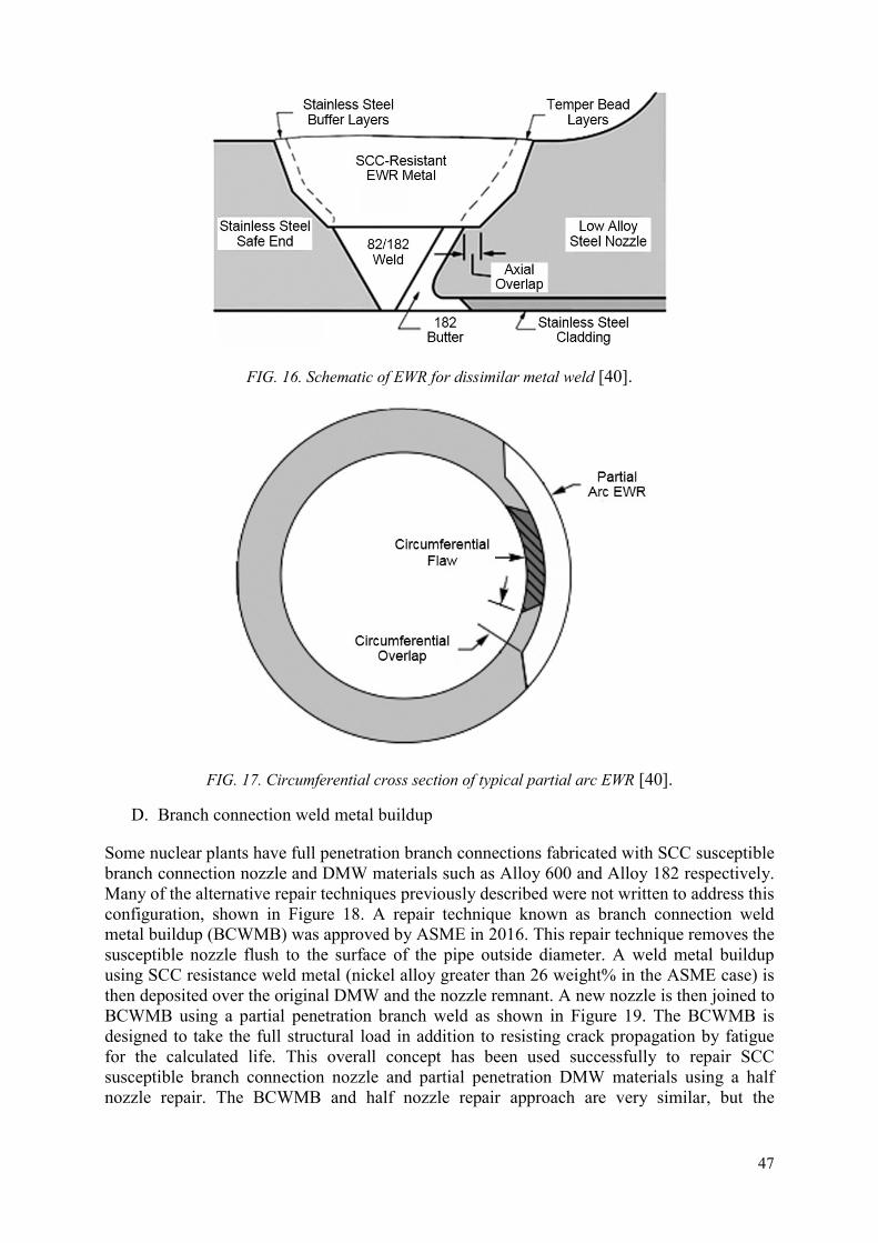
47
FIG. 16. Schematic of EWR for dissimilar metal weld [40].
FIG. 17. Circumferential cross section of typical partial arc EWR [40].
D. Branch connection weld metal buildup
Some nuclear plants have full penetration branch connections fabricated with SCC susceptible branch connection nozzle and DMW materials such as Alloy 600 and Alloy 182 respectively. Many of the alternative repair techniques previously described were not written to address this configuration, shown in Figure 18. A repair technique known as branch connection weld metal buildup (BCWMB) was approved by ASME in 2016. This repair technique removes the susceptible nozzle flush to the surface of the pipe outside diameter. A weld metal buildup using SCC resistance weld metal (nickel alloy greater than 26 weight% in the ASME case) is then deposited over the original DMW and the nozzle remnant. A new nozzle is then joined to BCWMB using a partial penetration branch weld as shown in Figure 19. The BCWMB is designed to take the full structural load in addition to resisting crack propagation by fatigue for the calculated life. This overall concept has been used successfully to repair SCC susceptible branch connection nozzle and partial penetration DMW materials using a half nozzle repair. The BCWMB and half nozzle repair approach are very similar, but the

48
BCWMB repair mitigates full penetration DMW which is the main difference. ASME Code Case N–853 [41] provides the technical requirements for applying a BCWMP.
FIG. 18. Typical full penetration branch connection [41].
FIG. 19. Modified configuration with BCWMB and partial penetration nozzle to BCWMB weld mitigation techniques [41].
4.3.1.5. Mechanical nozzle sleeve assembly (MNSA) [42].
The MNSA device is a proprietary mechanical assembly design. When the MNSA is attached to a vessel in the area of a leaking penetration tube, it provides structural stability and leak tightness around the tube. It should be noted that this type of repair is specific to nozzle geometry and may not be effective for all DMW locations. In addition, the use of this device normally requires the Owner to submit a relief request and obtain regulatory permission to modify the vessel configuration. The assembly consists of several parts that may be attached to the outer vessel wall either by mechanical bolting or by use of attachment welds. It is positioned around the leaking penetration tube on the vessel’s upper or lower head. A groove is usually machined in the penetration tube to allow for a mechanical interface with the
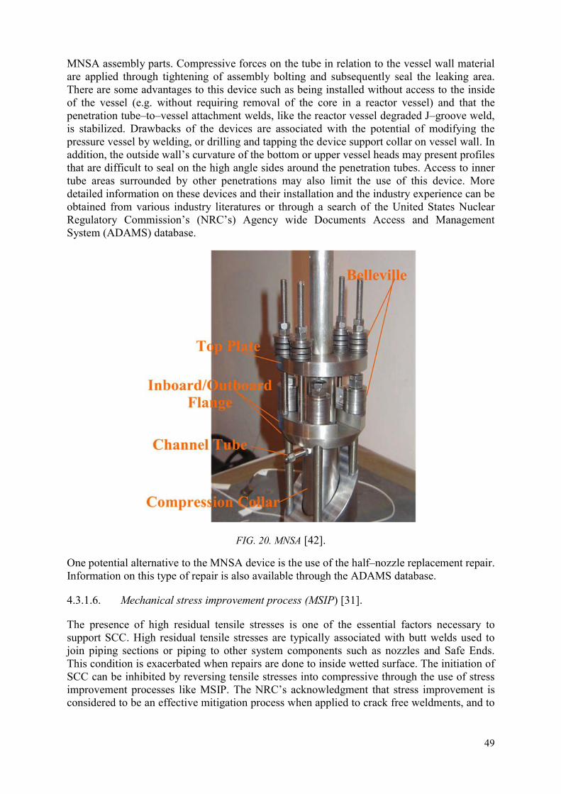
49
MNSA assembly parts. Compressive forces on the tube in relation to the vessel wall material are applied through tightening of assembly bolting and subsequently seal the leaking area. There are some advantages to this device such as being installed without access to the inside of the vessel (e.g. without requiring removal of the core in a reactor vessel) and that the penetration tube–to–vessel attachment welds, like the reactor vessel degraded J–groove weld, is stabilized. Drawbacks of the devices are associated with the potential of modifying the pressure vessel by welding, or drilling and tapping the device support collar on vessel wall. In addition, the outside wall’s curvature of the bottom or upper vessel heads may present profiles that are difficult to seal on the high angle sides around the penetration tubes. Access to inner tube areas surrounded by other penetrations may also limit the use of this device. More detailed information on these devices and their installation and the industry experience can be obtained from various industry literatures or through a search of the United States Nuclear Regulatory Commission’s (NRC’s) Agency wide Documents Access and Management System (ADAMS) database.
FIG. 20. MNSA [42].
One potential alternative to the MNSA device is the use of the half–nozzle replacement repair. Information on this type of repair is also available through the ADAMS database.
4.3.1.6. Mechanical stress improvement process (MSIP) [31].
The presence of high residual tensile stresses is one of the essential factors necessary to support SCC. High residual tensile stresses are typically associated with butt welds used to join piping sections or piping to other system components such as nozzles and Safe Ends. This condition is exacerbated when repairs are done to inside wetted surface. The initiation of SCC can be inhibited by reversing tensile stresses into compressive through the use of stress improvement processes like MSIP. The NRC’s acknowledgment that stress improvement is considered to be an effective mitigation process when applied to crack free weldments, and to

50
weldments having only short or shallow cracks, is detailed in Generic Letter 88–01 “Staff Position on Stress Improvement (SI) of Cracked Weldments”. Specifically, welds with cracks that are no longer than 10% of the circumference, and are no deeper than 30% of the wall thickness can be considered to be mitigated by SI.
MSIP is a mechanical process where forces are applied to the outside of a pipe wall so that it is constricted according to a prescribed displacement. The design of the MSIP device is a collar shape that conforms to the outside circumference of the pipe. It is installed over the pipe at a position adjacent to, but slightly offset from, the weld area where it is desired to have the improved stress profile. Special pads are used under to clamps to uniformly distribute the loading. Through hydraulics the clamp device is forced against the pipe wall to compress and bend the outer wall inward. The overall displacement is limited by the equipment design and is adjustable by use of shims. A small inward displacement deforms the pipe wall plastically and generates both axial and hoop compression strains. After the hydraulic clamp is released, a small permanent set is achieved and compressive stresses are maintained on approximately 50% of the innermost wall thickness — the location most vulnerable to SCC. Since the displacements are always compressive, the extension of prior small cracks is not a concern. MSIP does generate tensile stresses outboard of the pipe weldment in order to balance the compressive stresses that were generated; however, these stresses are generally distributed over a larger area well removed from any thermal effects due to welding. The use of MSIP has been applied widely and has been very effective for mitigating SCC of piping weldments.
FIG. 21. MSIP schematic [43].

51
FIG. 22. Basic concept of MSIP [44].
Modifying the residual stresses to a compressive state at the critical location is an effective way to mitigate the initiation of cracking due to fatigue or stress corrosion. All surface stress improvement processes are based on the same principle: deformation of the surface induces compressive residual stress in the surface layer of processed parts. The surface stress improvement processes differ principally in the surface deformation (method of deformation, with or without contact) and the residual stress and cold work profiles resulting from the deformation.
4.3.1.7. Peening
There are many stress improvement processes that have been developed for achieving desired residual stress modification on material surfaces for mitigating material degradation. These processes are commercially available (mostly for the aeronautic industry), such as shot peening and gravity peening, low–plasticity burnishing, ultrasonic peening, and abrasive water jet peening. Shot and gravity peening use the impact of small metallic or glass spheres with air blast or gravity to produce local deformation. Low–plasticity burnishing uses a free rolling spherical tool applied with a normal force to deform the surface. Ultrasonic peening uses an ultrasonic transducer to convert electrical energy into mechanical vibrations. Abrasive water jet uses high–pressure jets in combination with shot or abrasive particles. All of these processes use particles (for shot peening, gravity peening, and abrasive water jet peening) or tools (for lo–plasticity burnishing and ultrasonic peening) and can be categorized in methods deforming the surface with direct contact of a solid material on the treated surface, which can be an issue in a nuclear power plant environment [45].
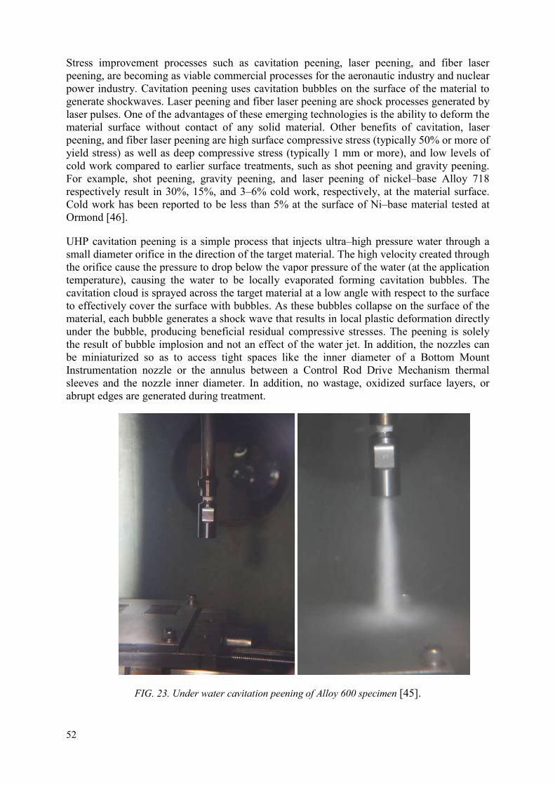
52
Stress improvement processes such as cavitation peening, laser peening, and fiber laser peening, are becoming as viable commercial processes for the aeronautic industry and nuclear power industry. Cavitation peening uses cavitation bubbles on the surface of the material to generate shockwaves. Laser peening and fiber laser peening are shock processes generated by laser pulses. One of the advantages of these emerging technologies is the ability to deform the material surface without contact of any solid material. Other benefits of cavitation, laser peening, and fiber laser peening are high surface compressive stress (typically 50% or more of yield stress) as well as deep compressive stress (typically 1 mm or more), and low levels of cold work compared to earlier surface treatments, such as shot peening and gravity peening. For example, shot peening, gravity peening, and laser peening of nickel–base Alloy 718 respectively result in 30%, 15%, and 3–6% cold work, respectively, at the material surface. Cold work has been reported to be less than 5% at the surface of Ni–base material tested at Ormond [46].
UHP cavitation peening is a simple process that injects ultra–high pressure water through a small diameter orifice in the direction of the target material. The high velocity created through the orifice cause the pressure to drop below the vapor pressure of the water (at the application temperature), causing the water to be locally evaporated forming cavitation bubbles. The cavitation cloud is sprayed across the target material at a low angle with respect to the surface to effectively cover the surface with bubbles. As these bubbles collapse on the surface of the material, each bubble generates a shock wave that results in local plastic deformation directly under the bubble, producing beneficial residual compressive stresses. The peening is solely the result of bubble implosion and not an effect of the water jet. In addition, the nozzles can be miniaturized so as to access tight spaces like the inner diameter of a Bottom Mount Instrumentation nozzle or the annulus between a Control Rod Drive Mechanism thermal sleeves and the nozzle inner diameter. In addition, no wastage, oxidized surface layers, or abrupt edges are generated during treatment.
FIG. 23. Under water cavitation peening of Alloy 600 specimen [45].

53
FIG. 24. Under water cavitation peening of Titanium Alloy [45].
FIG. 25. Laser peening process: (a) Set-up of work piece, ablative layer, inertial tamping layer, and incoming laser beam and (b) A high pressure plasma is generated by the laser impact, resulting in a pressure wave from the laser impact [45].

54
FIG. 26. Fiber laser peening of bottom mounted nozzle (BMN)-size specimen (left) and BMN mock-up (right) [45].
Qualification requirements for stress improvement processes vary greatly on existing code rules and regulatory environment. This variation is especially applicable for countries that have yet to implement a stress improvement processes. In these situations, it is not known what will be mandated to approve the repair such as mock–ups, analyses, etc. However, typical requirements for qualification include demonstrating via mock–up or analysis the depth of compression (assuming construction weld repair was made in the area being treated), resultant compression during normal operating conditions (start up, operating, shutdown), crack growth analysis of existing flaws, and analysis or testing to demonstrate that undesirable effects do not occur after treatment [47].
Recently, the US Nuclear Regulatory Commission (NRC) provided a safety evaluation dated August 24, 2016 regarding the use of peeing for mitigation of PWSCC. Their review was specific to EPRI Material Reliability Program (MRP)–335 “Materials Reliability Program: Topical Report for Primary Water Stress Corrosion Cracking Mitigation by Surface Stress Improvement (Peening)”[46] which was developed to demonstrate the effectiveness of surface stress improvement processes as a mitigation method, and subsequently provide inspection relief for peened components. The NRC noted during their evaluation that it was not based on specific peening processes, but on the resultant performance criterion (e.g. depth and magnitude of compression, inspectability, etc.). This is important because it supports the MRP’s position that any peening process that demonstrates effectiveness and meets specific performance criteria can be used to mitigate SCC. Thus, it is not necessary for a preening process to be included in the MRP document for it to be accepted under the NRC safety evaluation. The NRC staff did provide some conditions regarding inspection requirements.
The NRC concludes the safety evaluation with the following paragraphs:
“The NRC staff finds that MRP–335R3 [46] has adequately described the affected components, processes for peening, the supporting analyses of the peening application, testing

55
used to verify the effectiveness of peening, and the proposed inspection requirements of peened components. The NRC staffs also finds that the MRP has demonstrated that there is a beneficial effect from peening on the residual stress in the DMW and RPVHPN. The MRP has demonstrated by mock-up testing as shown in MRP–267, Revision 1 and analyses in MRP–335R3 [46] that the peening application will achieve a certain post–peening stress profile to minimize PWSCC initiation. Based on information provided in MRP–335R3 [46], and operating experience such as shot peening applied to steam generator tubes and abrasive water jet machining (peening) applied to repaired RPVHPNs, the NRC staff finds that peening application is a viable mitigation to minimize PWSCC initiation.
However, the NRC staff had questions regarding the details of the peening application, such as the adequacy of the post–peening stress field, the compression stress depth, and the potential for the small flaws that are not detected before peening that may grow after peening. The NRC staff finds that, given the input variables proposed in MRP–335R3 [46], the analyses provided do not fully support the inspection intervals proposed in MRP–335R3 [46]. Therefore, the NRC staff has imposed conditions to ensure that the proposed inspection requirements in MRP–335R3 [46] will provide adequate monitoring of the peened DMWs and RPVHPNs between required inspections.”
It recommended that those interested in pursuing peening as a mitigation method to review MRP–335 Revision 3–A [45] for more information. Some of the questions and concerns from regulators outside of the US may have been addressed in MRP–335 Revision 3–A [46] and it could be a useful reference.
4.4.REPAIR PLAN
A well–designed repair plan is crucial for the success of implementing a weld repair to mitigate SCCs. At the very least, a repair plan should include:
Design of the weld repair; Review the codes, standards and regulatory requirements; Select the process for repair/mitigation (welding or not welding process); Perform safety analysis; Follow the design change process; Revise documents (procedure, drawings, ISI program and others); and Development of the welding process and execution.
The concept of the weld repair would have to be designed with reference to the design base requirement and the relevant regulation, code and / or code cases. The design of the repair should consider the post–repair inspection requirement for the future monitoring of the integrity of the repair, i.e. does the repair lend itself for the inspection technique. Elements in for consideration in the design of the repair:
Repair with water backing or without water backing; Excavation of a defect completely or partially or no excavation of a defect; Meeting code requirement; Any previous concession / relief from the regulatory if the repair does not meet the
code; Accessibility;

56
In–house capability or vendor-provided repair service; Availability of qualified welders / welding operators; Worker radioactive dosage exposure minimization; Worker welding fume exposure minimization; and Operating experience (OE).
If the contemplated repair cannot fully be in compliance with the regulation requirement or code due to its impractical aspect, a request to the regulatory authority for their approval for the deviation or variance would be required. Depending on the nature of the request, it can be a lengthy process. The repair schedule would have to be adjusted to allow this review process.
4.4.1. Repair method development
When choosing a weld repair method, extensive development work will not be required if a proven repair methodology exists. The method can be modified to accommodate the field condition. A high fidelity mock–up will have to be in place to test out the method to ensure that the field condition can be accommodated for the weld repair and post–repair inspection. The mock–up can also serve as pre–production qualification or demonstration of new tooling or any changes in configuration. Another important attribute is that the mock-up also provides the welders additional practice with the materials being used in the repair. The materials, as will be discussed next, can be a significant challenge for obtaining a successful repair.
An important welding consideration during repair plan/method development is the weldability of the selected filler metal(s). The weldability or ease of welding, of filler materials can be one of the largest challenges to overcome from procedure qualification to field implementation. In particular, high nickel alloy filler metals have relatively poor weldability such as problematic issues in the form of hot cracking or ductility dip cracking. In addition, the sluggishness of the weld puddle and tendency to form oxides can create challenges for the welder which can lead to lack of bond type defects. Over the years, a lot of studies and research have been performed to mitigate the issues. Any change in filler metal selection of the weld repair should be adequately evaluated to ensure welds with acceptable quality can be repeatedly produced.
Use of high chromium nickel based filler metals, such as 52 and 52M, has been found to be effective in mitigating SCC. The microstructures of welds using these filler metals are fully austenitic. Operating experience with these alloys has shown that the welds are vulnerable to defects in the forms of cracking, lack of bond and porosity.
Two types of micro–cracks (micro–fissures) of ~0.25–2 mm in magnitude are commonly discovered in the post weld inspection, namely ductility dip cracks and solidification cracks. Ductility dip cracking (DDC) is a phenomenon where the weld metal exhibits a drop of ductility upon the weld reaching an elevated temperature (below the liquidus). DDC occurs in temperature ranges below the solidus of the filler metal on cooling, typically between 650–1200°C. The loss of ductility results in small separations of grain boundaries, creating microfissures. Thermal or mechanical strains, such as those developed in high–restraint welds, further exacerbate the phenomenon and can result in much larger cracks. DDC occurs primarily in previously deposited weld beads in multiple pass welds. Hence, DDC is often found in overlays where multiple layers of welds are deposited. DDC can be difficult to detect by current ultrasonic testing (UT) methods and might have serious consequences in critical applications. Under a constraint from contraction upon cooling, micro–cracks can form along

57
migrated dendritic grain boundaries. This is particularly so in cases where the defect tolerance is low and repair is both difficult and costly, such as nuclear applications where volumetric examination is required for all critical welds. (Figure 27 to show a typical DDC)
The presence of some level of ductility dip cracks are expected in fully austenitic high nickel welds. Discovering clusters of micro–fissures does not necessarily result in an unacceptable weld. The inspection criteria in the specific code being used may allow permissible amounts of clusters indications. Other codes and standards may be more stringent when compared to American standards (ASME Code). Defining realistic acceptance criteria of indications and defects in a site or procurement specification is important to avoid unnecessary rejection of “acceptable welds”. This criteria would have to be realistically established based on the input of the potential repair vendor (if applicable), code / standard acceptance criteria and owner’s engineering specification [48].

58
FIG. 27. Two examples of DDC in Alloy 52M [31].
Hot–cracking is another cause of crack–like defects found in welds of fully austenitic microstructure. Two mechanisms are identified to be responsible for hot–cracking, solidification cracking and liquation cracking. Solidification cracking is a result of weld shrinkage stresses and the weakening of grain boundary due to undesirable alloy impurities such as sulphur, phosphorus and silicon, which promote low melting point constituents. Liquation cracking happens in the grain boundary of the heat affected zones between weld passes. A thin film of liquid (unsolidified layer) of lower melting temperature than the bulk of material weakens the grain boundary. As a weld pool further cools, the stresses from the contraction causes separation at the grain boundary with a thin film of liquid. Welds of 100% austenite, typical of high nickel alloy, tends to form long and straight solidification dendrites which are highly susceptible to hot cracking. Hot cracking can be exacerbated by improper welding parameters which results in excessive heat input and unwanted amount of dilution from the base metal which has impurity elements [48].

59
FIG 28. Hot cracking in an Alloy 52 weld deposit [48].
Some filler materials are more susceptible to hot cracking than others, and Alloy 52 is particularly prone to cracking of both DDC and hot cracking. Many weld tests have been devised over the years to determine how susceptible a filler metal is to hot cracks. Through much of this testing two broad solutions can be applied to minimize the presence of hot cracking by filler metal composition or by dilution control. Filler wire manufacturers improve the resistance to such phenomena by controlling the composition to improve grain boundary strength. One approach is to add elements to the composition that tie up the impurity segregates to render them harmless or to increase grain boundary strength directly. Another strategy is the creation of a filler material composition with increased amounts of liquid available to backfill any cracks formed at the end of solidification. Developing certain welding parameters or techniques for base materials with higher amounts of deleterious elements (S, P, Si) can also minimize hot cracking by reducing weld dilution. Therefore, hot cracking is controlled both by filler metal composition and welding process parameters and techniques [48].
Hot cracking has been seen during the application of structural weld overlays in the United States when applied over austenitic stainless steel substrate with elevated levels of phosphorus, sulphur, and silicon. Mitigation of hot cracking was done using a combination of new weld parameters and application of one or more buffer layers. A buffer layer(s) is applying one or more layers of austenitic stainless steel filler metal over the stainless steel base metal prior to depositing Alloy 52. The buffer layer(s) effectively dilute the deleterious elements to a level that Alloy 52 can be applied without experiencing hot cracking. Weld parameters were reviewed and optimized for specific base material substrates. These parameters were developed to minimize weld dilution with the base metal. However, low dilution weld parameters may cause lack of fusion type defects on some base metal substrates and should not be used without prior evaluation. These two techniques are effective at mitigating hot cracking when proper planning and evaluation of the base metal substrate is done prior to attempting the repair.
Lack of bond or lack of fusion defects can be primarily attributed to improper welding parameters, techniques, and experience welding high nickel alloys. Alloy 52 type filler metal

60
produces a weld puddle that is sluggish and can have a significant amount of oxides on the weld surface contributing to welding difficulties. The use of uphill welding progression and interlayer cleaning has assisted in the reduction of these types of defects and reducing trapped oxides. Additionally, Alloy 52M was developed specifically to minimize surface oxides which assisted in reducing the amount of interlayer cleaning.
Porosity is another welding discontinuity that can occur during welding in general. It has been observed during welding with Alloy 52. The causes of porosity have typically been found to be improper shielding gas coverage, issues with gas lines, and surface contaminants (e.g. oil, water, etc.). Ensuring gas shielding system and surface cleanliness are maintained should reduce occurrences of porosity.
4.4.2. Development and variations of Filler Metal 52 [48]
There has been a considerable amount of research related to Alloy 690 compatible filler materials since the early 1980s. This included a number of experimental heats for alloys 52, 152, and 72. Weldability issues with a few heats of materials were identified in early EPRI research, but in general, the filler metals appeared to perform adequately. Research by the U.S. Navy and others identified cracking that was found in tube–to–tube sheet welds, as reported by Special Metals. These findings led to investigations by Special Metals and others to determine the cause of the cracking and associated remedies. The metallurgical phenomenon was DDC and it was determined to be the root cause for cracking.
Several organizations have continued researching Alloy 52 with objectives to eliminate DDC while increasing weldability. This effort has created variations of Alloy 52 each with unique characteristics. The list below is presented to provide a history of the Alloy 52 variants, reasoning for the changes, and hopefully clarify any confusion regarding the designations/trademarks.
Alloy 52 [AWS A5.14 ErNiCrFe-7]: Original chemistry, still manufactured for single–layer overlays and other industries. (Applied at Hope Creek in 1997.)
Alloy 52M [AWS A5.14 ErNiCrFe-7A]: The M designation refers to changes in the alloy composition to reduce deoxidizers (i.e. Al and Ti), the result is a reduction of oxide inclusions and surface oxide buildup. This could eliminate or reduce the amount of grinding required before applying the next weld layer(s).
Current Alloy 52M [AWS A5.14 ErNiCrFe-7A]: The M designation refers to changes in the alloy composition to reduce deoxidizers (i.e. Al and Ti), the result is a reduction of oxide inclusions and surface oxide buildup. In addition, the wire has improved cleaning processes during wire drawing. This version of the filler material was used in a large diameter weld overlay with no defects.
Alloy 52MSS [AWS A5.14 ErNiCrFe-13]: The M designation refers to the final chemistry (-M), manufacturing process (-S), and serpentine grain boundaries (-S). This 52 variant has the additions of roughly 2.5 % Nb and 4.0 % Mo and was targeted to eliminate DDC. Solidification cracking can still be an issue as it is with every heat of Alloy 52 filler material.
Alloy EN52i [AWS A5.14 ErNiCrFe-15]: This filler material was developed to have similar welding properties of Alloy 82 with increased amounts of chromium to resist PWSCC. This high chromium variant is targeted to have a nominal composition of 27% Cr, 2.5% Fe, 3.0%
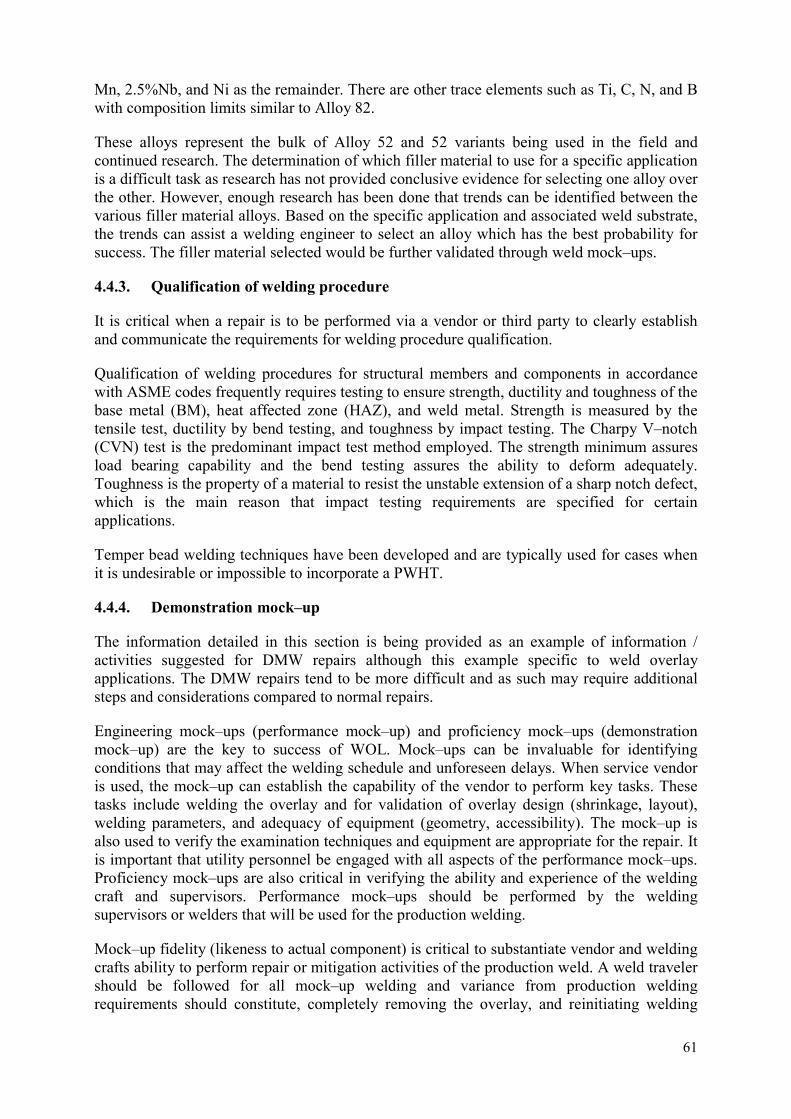
61
Mn, 2.5%Nb, and Ni as the remainder. There are other trace elements such as Ti, C, N, and B with composition limits similar to Alloy 82.
These alloys represent the bulk of Alloy 52 and 52 variants being used in the field and continued research. The determination of which filler material to use for a specific application is a difficult task as research has not provided conclusive evidence for selecting one alloy over the other. However, enough research has been done that trends can be identified between the various filler material alloys. Based on the specific application and associated weld substrate, the trends can assist a welding engineer to select an alloy which has the best probability for success. The filler material selected would be further validated through weld mock–ups.
4.4.3. Qualification of welding procedure
It is critical when a repair is to be performed via a vendor or third party to clearly establish and communicate the requirements for welding procedure qualification.
Qualification of welding procedures for structural members and components in accordance with ASME codes frequently requires testing to ensure strength, ductility and toughness of the base metal (BM), heat affected zone (HAZ), and weld metal. Strength is measured by the tensile test, ductility by bend testing, and toughness by impact testing. The Charpy V–notch (CVN) test is the predominant impact test method employed. The strength minimum assures load bearing capability and the bend testing assures the ability to deform adequately. Toughness is the property of a material to resist the unstable extension of a sharp notch defect, which is the main reason that impact testing requirements are specified for certain applications.
Temper bead welding techniques have been developed and are typically used for cases when it is undesirable or impossible to incorporate a PWHT.
4.4.4. Demonstration mock–up
The information detailed in this section is being provided as an example of information / activities suggested for DMW repairs although this example specific to weld overlay applications. The DMW repairs tend to be more difficult and as such may require additional steps and considerations compared to normal repairs.
Engineering mock–ups (performance mock–up) and proficiency mock–ups (demonstration mock–up) are the key to success of WOL. Mock–ups can be invaluable for identifying conditions that may affect the welding schedule and unforeseen delays. When service vendor is used, the mock–up can establish the capability of the vendor to perform key tasks. These tasks include welding the overlay and for validation of overlay design (shrinkage, layout), welding parameters, and adequacy of equipment (geometry, accessibility). The mock–up is also used to verify the examination techniques and equipment are appropriate for the repair. It is important that utility personnel be engaged with all aspects of the performance mock–ups. Proficiency mock–ups are also critical in verifying the ability and experience of the welding craft and supervisors. Performance mock–ups should be performed by the welding supervisors or welders that will be used for the production welding.
Mock–up fidelity (likeness to actual component) is critical to substantiate vendor and welding crafts ability to perform repair or mitigation activities of the production weld. A weld traveler should be followed for all mock–up welding and variance from production welding requirements should constitute, completely removing the overlay, and reinitiating welding

62
sequence. A high fidelity mock–up is an opportunity to mimic the exact welding, paperwork, inspections, etc. that will be done in the field.
For a complex repair such as welding overlays, one engineering mock–up of each configuration should be performed to an acceptable (no rejectable) result. If rejectable flaws are identified, additional mock–ups should be performed until no rejectable conditions are achieved and causes of rejectable flaws are evaluated. This is good practice and should not be considered optional. Welding should not commence in the plant until all issues that occurred during the mock–up are resolved. Utility personnel should also consider this an opportunity for the service provider or utility (when welding is self–performed) to demonstrate their contingent repair process (i.e. how they would repair and inspect a rejectable flaw). The utility should also ensure the repair procedure / traveler is followed during the repair process.
Proficiency mock–ups completed using production equipment and personnel have been considered a best practice for difficult repairs. The scope of proficiency mock–ups should include activities (as applicable to site conditions): sealing a leak / localized thinned area, localized weld repair, and overall welding. Each welder / welding operator should have demonstrated the ability to successfully perform all welding activities that may be necessary during field implementation. Examples of welding activities that should be demonstrated for a weld overlay are pre–weld cleaning, WOL layout, weld orientation, component material and configuration, welding parameters and equipment, safety requirements and practices, and welding personnel. Each is described below in further detail.
4.4.4.1. Pre / post–weld cleaning
The immediate WOL area and adjacent area need to be made accessible for associated tooling and personnel. The WOL area and adjacent base material surface area need to be cleaned for welding and pre–weld inspection as will be done during field welding. This could also involve some surface preparation such as grinding or machining. In addition, the post weld overlay machining and final cleaning is important for ensuring successful surface and volumetric examination. The cleaning and surface preparation process(es) used during the mock-up for both pre / post weld overlay should reflect those that will be used during field implementation. It is also recommended that NDE personnel be involved during this and other mock–ups to ensure final surface preparation meets the requirements to perform the required examinations.
4.4.4.2. WOL layout
Start and stop locations of the overlay should be identified with punch marks. Punch marks should also be placed at a location removed from the start and stop so they remain visible after the first layer of weld is deposited. The punch marks away from the weld toes are frequently used for determination of shrinkage. Thus, they are important for post–overlay calculations and their importance should be communicated to the craft. If punch marks are consumed by weld or cleaning process, punch mark locations should be verified and replaced immediately.
4.4.4.3. Machining
The surface preparation required for performing the repair should be demonstrated to ensure the effectiveness of the craft, equipment, and procedures. Demonstrating this activity is important to minimize issues during field implementation such as delays due to equipment / tooling failures or improper preparation. One additional example of an issue experienced

63
during this phase was incorrect location of machining on the component due to machining operator and procedure errors. It should be noted that some member states could require the machining activity to be qualified prior to being used in the field.
4.4.4.4. Weld orientation
Welding positions that will be found in the field should be maintained for all activities including:
Welding (engineering mock–up and demonstration mock–up); Interpass / interlayer cleaning; and Contour grinding and measurements.
4.4.4.5. Component material and configuration
Nozzle size (diameter) and geometry may affect arc voltage control (AVC) reaction, travel speed, and wire feed speed, which have implications to chromium recovery and TB requirements. Chromium recovery refers to the amount of chromium in the deposited filler metal after dilution with existing base and filler metals. The use of high chromium filler metals around 26% and greater are used (e.g. Alloy 52M) to minimize SCC in BWR and PWR environments. However, the amount of chromium in these filler metals decrease via dilution when they are deposited over existing base and filler metals with lower chromium content. Therefore, many ASME Code Cases for repair of DMWs require that chromium content be measured on the production weld or a mock–up to verify minimum chromium content. The minimum amount of chromium is specified to be 20% for BWR and 24% for PWR applications. The thickness of the deposited weld metal can be credited towards the repair once the minimum chromium content has been achieved [36, 38–40].
A minimum amount of delta ferrite is frequently specified by ferrite number when austenitic stainless steel filler metal is used in the repair. The calculation of the ferrite number should also be done during the production weld or mock–up when austenitic filler metals are used. It is important to note that the minimum chromium content and ferrite number requirements for nickel alloys and austenitic stainless steel respectively are intended for SCC susceptible regions. Thus, for regions (materials) that are already resistant to SCC those requirements have little purpose. However, this should be discussed internally and with the respective regulatory agency for agreement.
Mock–ups should reflect the nozzle and pipe geometry for all parameter development, and equipment set–up trials. Nozzle geometry that affects the welding (that is, the overlay length and thickness) should be reflected in mock–up welding demonstrations. Mock–ups should accurately depict the production weld including the following:
Elbows; Transitions; Diameter; Weld locations (using same filler metal as seen in the field); Clearances and physical restrictions: minimum clearances in all directions should be
recorded and utilized during mock–up welding; and Weld Restrictions (distance to control room, cable lengths).

64
A thorough walk down of welding area with accurate mapping of components, clearance and restrictions is critical for successfully mobilizing welding equipment and verifying the complete range of travel of welding head and carriage.
The mock–up should consist of like base material (such as cast stainless), weld material (DM weld), buttering, and cladding since the mock–up could be used to verify chemistry requirements (chromium recovery), temper bead parameters verification tests, material weldability issues, and verification of shrinkage measurements. If actual material is not available, a review of CMTRs should be conducted to highlight potential material welding issues such (as hot cracking). Weld filler material should be consistent (same heat) as productions weld. Alternative filler materials should not be used for performance or proficiency mock–ups.
4.4.4.6. Welding parameters and equipment
Welding parameters and conditions for production welds should be verified to be consistent with mock–up welds. Welding parameter verification should include wire size, power supply, track, wire feed speed, travel speed, heat input, welding head, torch angle, welding position, shielding gas etc. Equipment intended for production welds should be of the same make and model used for mock–up welding and training. Equipment issues should be reviewed during mock–up welding activities. This includes power supply, control panel, monitoring, carriage / track, lead length, and weld head configuration.
4.4.4.7. Safety requirements and practices
Safety procedures and practices may directly affect the performance and should be implemented in the mock–up demonstration. All safety conditions should be verified and reviewed during mock–up welding and include items like the following:
ALARA; Hexavalent chrome practices; Fall protection; PPE; FME—fall or catch basin / tarp for tools; Protective clothing; Confined space (argon buildup); Electrical shock hazard; and If Thoriated tungsten is used, precautions should be taken when grinding to ensure
the dust is not inhaled by personnel. Station personnel should inform the service provider (if applicable) if thoriated tungsten is not permitted on–site during planning stages of the weld overlay. Station personnel should ensure the service provider has developed or verified welding parameters have not changed if there is a switch from thoriated tungsten to non–thorium bearing tungsten electrodes.
4.4.4.8. Welding personnel
Welding personnel should have prior experience with filler metal and base metal used during repair activities. Filler metal like Alloy 52 requires practice and experience to achieve acceptable results.
Consideration for the production welding personnel includes:
65
Involvement with all aspects of the mock–up welding:
(a) Interlayer cleaning; (b) Profile requirements; (c) Leak sealing techniques; and (d) Weld bead log and bead map (consistency in comments and required
documentation).
Familiar with intricacies of welding with filler metal used during repair:
(a) Chemistry requirements (e.g. chromium recovery); (b) Temper Bead (TB) welding criteria; and (c) Demonstrate ability to maintain taper and length of overlay on mock–ups. Familiar with measurement techniques (quality control function):
(a) Template for contour measurements and monitoring; (b) Shrinkage measurement techniques and locations; and (c) Thickness measurement techniques and locations;
All welders’ performance qualifications and training should be documented and reviewed during mock–up welding activities and prior to production welding.
4.4.5. Inspection
The information detailed in this section is being provided as an example of information / activities suggested for DMW repairs although this example specific to weld overlay applications.
UT inspection should be performed (e.g. PDI) on mock–up to verify quality of weld. Interlayer inspection (PT) should be considered. Verify if other activities can interfere with qualified UT inspection (that is, grinding, welding, and so on). Discussing and addressing these considerations early will minimize surprises during actual application.
4.5.QUALIFICATION OF PRE–SERVICE INSPECTION
The licensee shall ensure that testing in connection with installation and repairs of installed components are performed by an approved laboratory in accordance to the countries regulation.
Testing in connection with manufacturing of materials and semi–finished products may nevertheless be performed by the manufacturing organization if it applies a quality assurance system to control testing activities that is certified by an authority.
Non–destructive examination in connection with inspections must be performed using either:
A well proven examination system that has been demonstrated as capable of reliably identifying and classifying the faults and deviations that the processes of repair, manufacturing and installation might give rise to, or;

66
Examination systems that to a sufficient extent have been qualified and assessed by an independent qualification body.
4.6.REPAIR AND IMPLEMENTATION
4.6.1. Construction and inspection plan
The organization that performs repair / replacement activity should establish documentation that defined manufacturing techniques and inspection methods and criteria. This programme should follow general requirement of licensee and it should follow repair (construction) code and authority requirement. Approval process required in authority requirements must be followed. This programme is defined typically in construction plan.
Minimum content of construction plans are:
Reference to requirements and standards that are followed; Classification of component; Organizations for manufacturing, inspection and quality control; Summary by the design organization of how the design bases are met; General design, calculations and drawings; and Construction materials, welding consumables and coatings used.
An item to be use for repair / replacement activities should meet the Construction Code. A defect can be only removed however minimum material thickness should not be less than the minimum required thickness. It this is the case the component should be corrected. Surface examination after removal of defect is typically required prior to welding. After repair inspections according, construction code should be followed. DMW's might have limitations accessibility and penetrant surface inspections are replaced with eddy current. These case limitations of eddy current technique should be noticed. Techniques should be selected so that all orientations can be inspected.
After examination inspections according, construction code and PSI should be done. Also, same examination technique after repair should be used that was used for detection as far as possible. PSI is normally required and this fulfils this requirement. Principle for examination after repair is that same method should be used that was used for detection as far as possible. After repair PSI is normally required and this fulfils this requirement. Manufacturing inspections are not typically replacing pre–service inspection. Exceptions are typically in surface inspection. Pre–service inspections are done normally using qualified in–service inspection techniques to provide basic comparative data for the in–service inspections. Object is to get supplementing data to manufacture and installation inspections result to determine the original condition of the components when inspected within the in–service inspection techniques. As far as possible, the inspections should be conducted using the same methods, techniques and types of inspection equipment as are intended to be used in individual in-service inspections. If flaws are found in pre–service inspection acceptance criteria of in–service code (PSI) can typically be followed instead of construction code.
Pre–service inspections should be done after pressure test to components like nozzle to Safe End, if required. For piping welds like safe end to pipe inspections can be done before pressure test. PSI should be done always before approval to operation. This should be done

67
whenever an area inspected in a component or structure within the inspection scope is repaired, modified or replaced.
Materials, products and welded joints must undergo the inspections necessary in order to ensure that no defects or other deviations remain that have safety significance. The inspections must be performed in accordance with the relevant methods of design, repair and manufacturing together with the basis for the inspections adapted to the quality classification.
This work shall encompass:
Inspection plans clearly specifying the type and scope of inspections at different stages, in connection with repairs, during manufacturing and in connection with installation at the facility; and
The procedures and instructions necessary to define performance of inspections, non-destructive examination and other investigations.
4.6.2. Quality assurance programme
Quality assurance programme is plan where systematic actions are defined to ensure confidence that requirements are met. Quality assurance programme are done by organization that perform repair and its fulfilment followed by authority or regulatory. Purpose of this document is to ensure safety and quality–related risk management of project. Project management is established with the applicable standards like for example (ref 10CFR50 app. B) [49].
The 18 QA Basic requirements are applicable [50]:
1. Organization; 2. Quality assurance program; 3. Design control; 4. Procurement Document control; 5. Instructions, procedures and drawings; 6. Document control; 7. Control of purchase material, equipment, and services; 8. Identification and control of materials, parts and components; 9. Control of special processes; 10. Inspection; 11. Test Control; 12. Control of measuring and test equipment; 13. Handling, storage and shipping; 14. Inspection, test and operation status; 15. Nonconforming materials, parts, or components; 16. Corrective action; 17. Quality assurance records; and 18. Audits.
For repair / replacement, for example, WOL activities, the utility may write a special Quality Assurance Plan, especially if the utility has interface with vendors.

68
4.6.3. Vendor oversight / supervision
Utility oversight of welding contractor(s) is imperative to verify adherence to weld procedure specifications, schedule and ALARA need to be established and communicated prior to initiation of all welding applications (mock–up and production welds). The meaning of oversight / supervision may be different for each member state. The use of those terms in this section refers to utility providing assurance that the vendor is following procedures and the overall plan through surveillance and frequent engagement. These activities can be provided at the corporate or station levels, likely both. Oversight of all aspects of welding activities can be implemented by surveillance by the owner. Witnessing of critical steps is recommended and the witness points should be identified in an Inspection and Testing Plan. The key takeaway is that oversight is necessary and should be considered and planned before the repair takes place [48].
When the utility chooses a vendor to provide the repair service, it is important that: The vendor is including in the “qualified supplier list” — Vendor needs to follow a QA program (10 CFR 50 App requirement II); Stablish hold points during the process qualification — The utility needs to approve all the process. It is very important to stablish a sequential plan where all steps can be checked and approved by the contractor. (10 CFR 50 App B V requirement XIV and VII) Stablish a contract describing all technical specification (10 CFR 50 App B requirements IV and VIII).
Utility oversight of welding contractor(s) is imperative to verify adherence to weld procedure specifications, schedule and ALARA need to be established and communicated prior to initiation of all welding applications (mock–up and production welds). Oversight of all aspects of welding activities can be implemented by surveillance by the owner. Witnessing of critical steps is recommended and the witness points should be identified in an Inspection and Testing Plan. The key takeaway is that oversight is necessary and should be considered and planned before the repair takes place [45]. The Annex “V” is a model to utilities organizes hold points or witness points during the vendor activities.
It is very important the utility stablish witnessing of critical steps (hold points) during all vendor activities.
4.6.4. Before repair / replacement activity (mock–up welds)
The principal witness points (hold point) shall be during:
Weld Procedure Qualification; Machining Qualification; Personnel qualification; and Tests (destructive and non–destructive).
According to ASME Section IX [1]: “QW–100.1–The purpose of the Welding Procedure Specification (WPS) and Procedure Qualification Record (PQR) is to determine that the weldment proposed for construction is capable of providing the required properties for its intended application. It is presupposed that the welder or welding operator performing the welding procedure qualification test is a skilled workman. That is, the welding procedure qualification test establishes the properties of the weldment, not the skill of the welder or

69
welding operator. In addition to this general requirement, special considerations for notch toughness are required by other sections of the Code. Briefly, a WPS lists the variables, both essential and nonessential, and the acceptable ranges of these variables when using the WPS. The WPS is intended to provide direction for the welder / welding operator. The PQR lists what were used in qualifying the WPS and the test results.
QW–100.2 In performance qualification, the basic criterion established for welder qualification is to determine the welder’s ability to deposit sound weld metal. The purpose of the performance qualification test for the welding operator is to determine the welding operator’s mechanical ability to operate the welding equipment.”
Some member states require the complete repair process such as from initial surface preparation / inspection through actual repair to final inspections to be demonstrated / qualified. The qualification requirement could originate from the regulator or associated codes. Therefore, the member state should be aware of any potential requirements for qualifying the machining process so that it can be planned accordingly.
System tests (e.g. pressure or leak tests) after the repair or replacement activity has been completed should be considered during the planning stages of the project. The potential change in system configuration resulting from the repair or replacement activity could create challenges to perform the system tests. However, in some instances there are exemptions permitted for the system test requirements.
4.6.5. During the repair / replacement activities
All procedures shall be approved by the utility before it be used. The utility shall assure that the welding procedures employed and welders have been qualified according the mock–up welds. The vendor shall submit evidence to the utility that these requirements have been met.
5. OPERATING EXPERIENCES, LESSONS LEARNED AND RECOMMENDATIONS
This section includes a summary of lessons learned and recommendations that may be obtained from several international studies on DMW with different NDE techniques and procedures [51].
Lessons learned from NDE an inspection study on DMW shows that:
ID procedures provide superior performance over OD procedures for large bore nozzles (PWR–nozzles) measured by POD, depth sizing RMSE, and length sizing RMSE.
Inspections performed on small bore nozzles (BWR–nozzles) exhibit better performance than OD inspections performed on large bore nozzles based on POD and depth sizing RMSE.
Further, length sizing RMSE of axial flaws is also better for small bore nozzles in comparison to OD access of large bore nozzles.

70
Defect orientation has an influence on detection performance with circumferential defect exhibiting a greater likelihood of detection than axial defect, as a function of depth.
Defect orientation does not influence depth sizing performance based on depth sizing RMSE results for large bore nozzles and small bore nozzles.
Procedures that include ECT performed better at length sizing than procedures that do not include ECT, particularly for axial defect, as indicated by RMSE values.
PAUT performance is better than conventional UT performance for small bore nozzles as measured by POD and depth sizing RMSE.
PAUT performance is marginally better than UT performance for large bore nozzles as measured by POD and depth sizing RMSE.
Detected flaws might have influence to inspection qualification. Mitigation might have influence to cost due longer inspection interval.

71
Technique Case History
Risk-Informed Assessment of PWSCC Issue in CANDU Feeder Piping
Primary Water Stress Corrosion Cracking (PWSCC) is considered as a possible cracking mechanism for Dissimilar Metal Welds (DMWs) in outlet feeders at some CANDU plants. These DMWs join SA-106 carbon steel piping with Alloy 600 flow element and are fabricated using Gas Tungsten Arc Welding (GTAW) with filler metal Alloy 82 or Alloy 182. Based on the effective degradation years (EDY) method, DMWs at some CANDU plants with flow elements in the outlet feeders are currently in the high range prior to reaching end of life. These DMW welds shall be subject to periodic inspection as per the CSA N285.4–05 requirements because of the susceptibility to PWSCC. Due to the consideration of high radiological dose and the inherent difficulty of Non–Destructive Examination (NDE) technique associated with the feeder DMW inspection, a technical approach based on Risk–Informed Leak–Before–Break (RI–LBB) is being developed to support a request for inspection exemption of these outlet feeder DMWs. A tiered composite risk-informed LBB case has been developed for the postulated cracking of outlet feeder dissimilar metal welds. The deterministic LBB assessment shows that 90% of the DMWs at risk satisfy the five mandatory requirements: factor on load, factor on crack length, factor on leak rate, time from detectable leakage to rupture, and factor on consequential leakage. For the remaining 10% of the DMWs at risk have an insufficient factor on leak rate, the advanced FEA flaw evaluation demonstrates there are at least 58 days available for operator action to shut down the reactor. The probabilistic LBB assessment concludes that the 95th percentile of rupture probability from a single DMW is 5.95×10⁻⁸ and that even 100% inspection every outage (~2.5 EFPY) does not significantly reduce the rupture probability. Of the input parameters for the probabilistic LBB assessment, the operational leak detection limit has the most significant impact on the rupture probability and the influence of weld residual stress is important [52].
Cracking observed in the early 1990s in reactor components in France and other countries was attributed to PWSCC, leading to replacement of reactor vessel heads, piping, etc. The problem resurfaced in 2000 when, at the Oconee plant in the United States, leakage was discovered from a control rod drive mechanism penetration fabricated using Alloy 600, resulting in deposits of boric acid crystals on the vessel head. Further investigation led to the identification of PWSCC cracks in the reactor penetration tubes and attachment J–groove welds. Circumferential cracking of CRDM nozzles has been identified at Oconee Units 2 and 3 and Crystal River Unit 3. An extreme consequence of such cracking was illustrated by the discovery of wastage on the Davis–Besse reactor vessel head. More recently, boric acid deposits and NDE flaws found at the South Texas Project BMI nozzles have

72
been attributed to PWSCC.
Cracks also have been found in reactor nozzle hot leg dissimilar metal welds at the V.C. Summer plant in the United States and at the Ringhals plant in Sweden, providing further evidence that PWSCC is a generic concern [51].
In the USA there have been a number of events related to PWSCC in DMWs. A recent report by Sullivan and Anderson (2014) [53] examined the management of PWSCC in butt welds by mitigation and inspection. The report provides details and extensive references for these events in the USA as well as those that have been reported world–wide. The reader is directed to the US NRC website where this report can be downloaded (http://www.nrc.gov/reading–rm/doc–collections/nuregs/contract/cr7187/). The intent in this paper is to just highlight some of the salient features of these events that are relevant to these RRTs. The events in the USA began in 1993 at Palisades with PWSCC in the heat affected zone of a power–operated relief valve Alloy 600 Safe End located near the pressurizer. The most recent event occurred at the North Anna Power Station, Unit 1 in the ”B” reactor coolant loop hot–leg–to–steam generator nozzle weld in 2012.
There have been 17 events reported for butt weld PWSCC from 1993 through 2012. It is interesting to note that nearly one–half of these events involved PWSCC that had circumferential flaw orientation. Only one of these circumferential cracks had significant depth that was estimated to be 65% through wall in one location. The axial flaws were typically deeper in through wall extent than the circumferential flaws. Furthermore, a number of these PWSCC were discovered by non–NDE methods such as, water on the floor, accumulated boric acid deposits or leakage uncovered when the mitigation was being applied. This has raised some important questions about the effectiveness of the NDE being applied to detect PWSCC in DMWs and was one of the driving forces for the PINC and the PARENT programs. Since many of these examinations were conducted under the requirements of ASME Boiler and Pressure Vessel Code, Section XI, Division 1, Appendix VIII, questions for why the PWSCC have been missed remain. Many factors such as the NDE methods and technology being employed and the representativeness of the simulated PWSCC and component configurations in the Appendix VIII testing are being assessed to try to understand where improvements need to be made. The PINC and PARENT program results will hopefully, answer some of these questions and provide direction on what needs to be done so that there will be fewer events in U.S. NPPs. Thus, in the future NDE will find these conditions before leakage occurs and in a timely manner so that appropriate mitigation can be deployed [51].

73
Case studies from: Welding and Repair Technology Center: Repairs to Leaking American Society of Mechanical Engineers (ASME) Class Systems—Update. EPRI, Palo Alto, CA: 2015. 3002005537
5.1.ARKANSAS ONE (PWR) HALF NOZZLE REPAIR
In April 2010, Entergy submitted relief request R&R-013 for repair of a leaking pressurizer instrumentation nozzle using a “half nozzle” repair. This repair involves removal of the outer portion of the nozzle and boring into the pressurizer shell a fixed distance such that a small portion of the original nozzle remains intact—including the original Alloy 82 / 182 pressure boundary weld which had cracked due to PWSCC and caused the leakage. An Alloy 52M weld pad was then applied to the ferritic surface of the pressurizer using temper bead welding in accordance with Code Case N–638–1 to function as the new pressure boundary attachment. The pad was then bored slightly larger than a new Alloy 690 instrument nozzle, a weld groove was machined into the Alloy 52M pad, and the new nozzle was inserted through the pad and welded by partial penetration weld to the new Alloy 52M weld pad as shown in Figure 29.
FIG. 29, Arkansas Nuclear One: Half nozzle repair.
As an alternative to characterizing the actual size of the flaw and then calculating projected crack growth, Entergy assumed the worst case flaw and applied finite element fatigue analysis which demonstrated that the worst case flaw is acceptable for a 60 year plant operating period. Entergy also requested that the 48-hour time limit on performance of surface examination after completion of welding as required by Code Case N–638–1, to begin instead after the third temper bead weld layer was completed on the built–up pad.
Verbal approval was granted one week after the initial submittal, and the formal SER was issued in January 2011.

74
5.2.WELD OVERLAY USING CODE CASE N–504
US plant observed leakage from the 2 inch N–11 B–1 process pipe to Safe End location associated with Feedwater level instrumentation during the scheduled pressure test at the end of their refuelling outage. The leakage was characterized as approximately 15 drops per minute. Further characterization of the flaw utilizing a PDI / IGSCC qualified ultrasonic procedure determined the flaw to be oriented circumferentially and approximately 1.1 inch in length (ID) at the 11:00 position looking toward the nozzle. The flaw was located approximately 0.5 inches from the weld centreline in the austenitic stainless steel safe end side of the weld joint adjacent to the heat affected zone. The cause of the crack was concluded to be IGSCC promoted by excessive internal stresses resulting from ID boring of the forged Safe End during manufacture.
Replacement of the safe end was considered too time–consuming, and a permanent engineered weld overlay in accordance with Code Case N–504–3 was determined to be the best repair method. The automated GTAW process was selected to ensure the least change in chemical composition from the wire to the deposit, and to minimize dilution carryover as subsequent weld passes are applied. The utility requested and received verbal approval to utilize a system leakage test in accordance with IWA–5000 at nominal operating pressure and temperature in lieu of the system hydrostatic test required by Code Case N–504–3.
Design of the overlay called for a thickness of 0.13 inch and a minimum length of 0.8 inch, however these were increased to 0.15 inch and 0.20-inch depth and a minimum length 3.95 inch to accommodate ultrasonic volumetric examination.
FIG. 30, Applied Weld Overlay.
Internal pressure at the time of the repair was about 1 psig, and the temperature was approximately 130 degrees Fahrenheit. The indication was surface-examined by PT (water interfered with final interpretation, but a 3/16 inch rejectable linear indication was detected), and sized by ultrasonic examination. The weeping leakage was stopped prior to application of the overlay by peening the crack shut and seal welding. Punch marks were applied at four quadrants along the axis outside of the overlay zone for measurement of axial shrinkage. The final surface was machined to a 250 RMS finish to facilitate ultrasonic examination.
Post–repair NDE included liquid penetrant surface examination, ultrasonic volumetric examination, and VT–2 leakage examination during the system pressure test. Post–overlay measurements indicated significant shrinkage in both the radial and axial directions.
Follow-up UT inspections were performed in accordance with ASME Section XI, Appendix Q, Weld Overlay Repair of Austenitic stainless steel Piping. Extent of condition examinations involved immediate UT examination of the other instrument connections for all units. One

75
other 2 N12 connection was found to have an 80% through-wall crack, resulting in a similar overlay being applied the year after.
Lessons learned: Mock–up training, careful planning, attention to detail, and close vendor oversight are essential for a successful overlay repair.
5.3.DAVIS BESSE (PWR) FULL STRUCTURAL WELD OVERLAYS
(2008) Davis–Besse committed to fulfil the examination or mitigation schedule contained in MRP–139 for the applicable pressurizer welds by the end of 2007. To meet these requirements, Davis–Besse scheduled installation of full structural overlays on all welds containing 82 / 182 material in the scope of MRP–139 operating at or exceeding hot leg temperatures during the refuelling outage starting on December 31, 2007. No ultrasonic examinations were planned to be conducted on these welds prior to the weld overlays. However, due to a through–wall leak that resulted during one of the overlays, an ultrasonic examination was conducted on that weld without the overlay in order to characterize the flaw. Based on the flaw characterization this weld was then overlaid as planned.
5.4.PALO VERDE (PWR) MECHANICAL NOZZLE SEAL ASSEMBLY
(2004) Unit 3 had been shut down and was being maintained in Mode 3, Hot Standby, and while trouble shooting a turbine–generator excitation problem. While conducting a required boric acid walk down, engineering personnel discovered boric acid on the Class 1 pressurizer heater sleeve.
PVNGS submitted a relief request and was granted permission to defer detailed inspections until the next refuelling outage, and instead install a mechanical nozzle seal assembly (MNSA) at this time in accordance with a relief request previously approved for application at PVNGS. Inspection of the nozzle during the current unplanned outage would require placing the unit in reduced inventory, with the RCS breached for the duration of the inspection. Shutdown risk is higher in this condition than the condition required for installation of the mechanical nozzle seal assembly (MNSA).
FIG. 31 Palo Verde mechanical nozzle seal assembly (MNSA).
76
The cause of the boric acid leakage was attributed to PWSCC (primary water stress corrosion cracking) of alloy 600 materials in the pressurizer heater sleeve. The amount of boric acid found was small.
The MNSA is a mechanical device consisting of a split gasket/flange assembly that is placed around the leaking penetration. The gasket is made of Grafoil packing, a graphite compound that is compressed within the assembly to prevent RCS leakage past the penetration. The assembly is bolted into holes drilled and threaded on the outer surface of the pressurizer. Another assembly is bolted to the flanges, which serves as the structural attachment of the sleeve to the wall. This assembly serves to carry the loads in lieu of the J–groove welds on the Alloy 600 penetrations. Post installation testing of the MNSA at normal operating pressure and temperature demonstrated the acceptability of the installation.
77
REFERENCES
[1] ASME Boiler and Pressure Vessel Code, Section XI, Rules for In service Inspection of Nuclear Power Plant Components, Division1, Rules for Inspection and Testing of Components of Light water Cooled Plants, ASME International, USA (2001).
[2] INTERNATIONAL ATOMIC ENERGY AGENCY, Assessment and Management of Ageing of Major Nuclear Power Plant Components Important to Safety:Primary Piping in PWRs, IAEA-TECDOC-1361, IAEA, Vienna (2003).
[3] ENIQ Recommended Practice 2 Strategy and Recommended Contents for Technical Justifications Issue 3, ENIQ (2017) p. 37.
[4] WÅLE, J., “Crack Characterisation for In-Service Inspection Planning – An Update”, SKI, Stockholm (2006).
[5] JONES, R., Mitigation Corrosion Problems in LWRs via Chemistry Changes, EPRI, Palo Alto, CA (2004).
[6] SZAVAI, S., VVER Type Mock-up Manufacturing Report, Deliverable D3.3, (2012). [7] KOLKOORI, S., Quantitative Evaluation of Ultrasonic Wave Propagation in Inhomogeneous Anisotropic
Austenitic Welds Using 3D Ray Tracing Method: Numerical and Experimental Validation, Berlin (2014). [8] MUNIKOTI, V.., BREKOW, G., TESSARO, U., ERHARD, A., Ultrasonic testing for transverse
discontinuities in dissimilar welds, Mater. Eval. 62 (2004) 1148. [9] KURTULMUS, M., YUKLER, I., Effects of probe properties on ultrasonic inspection of austenitic
stainless steel weldments, Sci. Res. Essays 6 (2011) 305. [10] KAPRANOS, P.., WHITTAKER, V.., Difficulties in the ultrasonic inspection of 316 austenitic steel welds
arising from acoustic impedance mismatch, Nondestruct. Test. Commun. 1 (1983) 81. [11] CLAYTOR, T.., KUPPERMAN, D.., REIMAN, K.., Visualization of ultrasonic beam distortion in
anisotropic stainless steel, J. Phys. 46 (1985) 795. [12] ROBERTS, R.., KUPPERMAN, D.., Ultrasonic beam distortion in transversely isotropic media, Review
of progress in quantitative NDE, Eds Thompson Chimenti 7A (1988) 49. [13] INTERNATIONAL ATOMIC ENERGY AGENCY, Maintenance, Surveillance, and In-Service
Inspection in Nuclear Power Plants, IAEA Safety Standards Series No. NS-G-2.6, IAEA, Vienna (2002) 74 pp.
[14] SÄTEILYTURVAKESKUS (STUK), In-Service Inspection of Nuclear Facility Pressure Equipment with Non-Destructive Testing Methods YVL E.5, STUK, Helsinki (2014).
[15] WALE, J., Crack Characterisation for In-Service Inspection Planning, SKI 2006:24, SKI, Stockholm (2006).
[16] European Framework Document for Risk-informed In-service Inspection, ENIQ Report nr. 23, EUR 21581 EN, European Commission JRC (2005) p. 48.
[17] ENIQ Recommended Practice 6: The Use of Modelling in Inspection Qualification, Europear Commission JRC (2011).
[18] EN ISO 9712/NORDTEST SCHEME for examination and certification of non destructive testing personnel, ISO (2005).
[19] NDT Personnel Training, Qualification and Certification — Audit Checklist 2011 CP-189, (2012) 33 pp. [20] ENIQ RECOMMENDED PRACTICE 10 Personnel Qualification, European Commission JRC (2010). [21] INTERNATIONAL ATOMIC ENERGY AGENCY, Methodology for Qualification of In-Service
Inspection Systems for WWER Nuclear Power Plants, IAEA-EBP-WWER-11, IAEA, Vienna (1998). [22] European Methodology for Qualification of Non-Destructive Testing, 3rd Issue, EUR 22906 EN, nr. 31,
ENIQ, Luxembourg (2007). [23] FITNET, FITNET FFS MK7– Section 6, Fracture Module, MK7, FITNET (2006). [24] Assessment of the integrity of structures containing defects. British Energy Generation Report R/H/R6,
Revision 4, EDF (2001). [25] Guide to methods for assessing the acceptability of flaws in metallic structures. BS 7910:2013, (2013) 490
pp. [26] Root cause analysis, Guidance document, DOE Guideline, DOE-NE-STD-1004-92, Department of Energy
DOE (1992) p. 69. [27] INTERNATIONAL ATOMIC ENERGY AGENCY, Root Cause Analysis Following an Event at a
Nuclear Installation: Reference Manual, IAEA-TECDOC-1756, IAEA, Vienna (2015). [28] Material Reliability Program: Primary System Piping Butt Weld Inspection and Evaluation Guideline
(MRP-139, Revision 1), EPRI, Palo Alto, CA (2008). [29] ASME Boiler and Pressure Vessel Code, Section B, Part C, ASME International, USA (2015). [30] Materials Reliability Program: GE Experience Report on Cracking in Alloy 182 (MRP-57): BWR Alloy
182 Stress Corrosion Cracking, Palo Alto, CA (2001) p. 34.
78
[31] Welding and Repair Technology Center: Repair Welding Handbook, EPRI Palo Alto, CA, (2015) 148 pp. [32] Similar and Dissimilar Metal Welding Using Ambient Temperature Machine GTAW Temper Bead
Technique, Code Case N-740, ASME International, ASME International. [33] Similar and Dissimilar Metal Welding Using Ambient Temperature SMAW Temper Bead Technique,
Code Case N-839, ASME International, ASME International. [34] Temperbead Welding Repair of Low Alloy Pressure Vessel Steels, EPRI Palo Alto, CA, EPRI (1994) 266
pp. [35] ASME Boiler and Pressure Vessel Code, Section IX, Qualification Standard for Welding, Brazing, and
Fusing Procedures: Welders, Brazers: and Welding, Brazing, and Fucing Operators, ASME International, USA (2015).
[36] Full Structural Dissimilar Metal Weld Overlay forRepair or Mitigation of Class 1,2 and 3 Items, Code Case N-740, ASME International, ASME International.
[37] Specification and qualification of welding procedures for metallic materials -- Welding procedure test -- Part 1: Arc and gas welding of steels and arc welding of nickel and nickel alloys, ISO, Germany (2004) 28 pp.
[38] Optimized Structural Dissimilar Metal Weld Overlay for Mitigation of PWR Class 1 Items, Code Case N-754, ASME International, ASME International.
[39] MARLETTE, S.E. et al., Technical Basis for Case N-766-1 Nickel Alloy Reactor Coolant Inlay and Onlay for Mitigation of PWR Full Penetration Circumferential Nickel Alloy Welds in Class 1 Items, ASME International (2012).
[40] Partial Excavation and Deposition of Weld Metal for Mitigation of Class 1 Items, Code Case N-847, ASME International.
[41] ASME Boiler and Pressure Vessel Code, Code Case N-853-PWR Class 1 Primary Piping Alloy 600 Full Penetration Branch Connection Weld Metal Buildup for Material Susceptible to Primary Water Stress Corrosion Cracking Section XI, Division 1, ASME International, USA (2016).
[42] INTERNATIONAL ATOMIC ENERGY AGENCY, Stress Corrosion Cracking in Light Water Reactors Good Practices and Lessons Learned, IAEA Nuclear Energy Series No. NP-T-3.13, IAEA, Vienna (2011).
[43] FREDETTE, L., SCOTT, P., Evaluation of the Mechanical Stress Improvement Process (MSIP) as a Mitigation Strategy for Primary Water Stress Corrosion Cracking in Pressurized Water Reactors, NRC (2009) 153 pp.
[44] Materials Reliability Program: Mechanical Stress Improvement Process (MSIP) Implementation and Performance Experience for PWR Applications, EPRI, Palo Alto, CA (2004) 56 pp.
[45] Materials Reliability Program: Program on Technology Innovation: An Evaluation of Surface Stress Improvement Technologies for PWSCC Mitigation of Alloy 600 Nuclear Components (MRP- 162), EPRI Palo Alto, CA, EPRI, Palo Alto, CA (2006).
[46] Materials Reliability Program: Topical Report for Primary Water Stress Corrosion Cracking Mitigation by Surface Stress Improvement (MRP-335, Revision 3-A), EPRI (2016).
[47] ASME BPVC Section XI, Division 1, Code Case N-770. “Alternative Examination Requirements and Acceptance Standards for Class 1 PWR Piping and Vessel Nozzle Butt Welds Fabricated With UNS N06082 or UNS W86182 Weld Filler Material With or Without Application of Listed Mitigation Activities, ASME International (2015).
[48] Welding and Repair Technology Center: Overlay Handbook, Palo Alto, CA (2013) 246 pp. [49] Domestic Licencing of Production and Utilization Facilities, Title 10, Code of Federal Regulation Part 50,
United States Nuclear Regulatory Commission, U.S.NRC. [50] Quality Assurance Criteria for Nuclear Power Plants and Fuel Reprocessing Plants. Appendix B to Part
50, NRC (2013). [51] ZETTERWALL, T., Effectiveness Evolution of DMW Inspection Techniques Assessed Through Three
International RRT’s, Jeju Island Rep. of Korea (2015). [52] Xinjian Duan, Ming Li, Min Wang Risk-Informed Assessment of PWSCC Issue in CANDU Feeder Piping
17th International Conference on Environmental Degradation of Materials in Nuclear Power Systems- Water Reactors, Fairmont Chateau Laurier, Ottawa, Ontario (2015).
[53] EDELMANN, X., Ultrasonic examination of austenitic welds at reactor pressure vessel, Nucl. Eng. Des. 129 (1991) 341.
79
GLOSSARY
Defect. Macroscopic imperfection. Includes flaws as well as other macroscopic imperfections like over penetration in welds that exceed acceptance standards
Degradation. Phenomena or process that attacks (wear, cracking etc.) the component material and might result in a reduction of component integrity
Flaw. An imperfection or discontinuity that may be detectable by NDE and is not necessarily rejectable
Indication, The response or evidence from the application of a NDE inspection
Inspection qualification. The systematic assessment, by all those methods that are needed to provide reliable confirmation, of an inspection system to ensure it is capable of achieving the required performance under real inspection conditions
Inspection system. All parts of the non-destructive examination including equipment, inspection procedure and personnel which can influence the outcome and quality of inspection
In–Service Inspection (ISI). A periodic non-destructive examination of NPP components in order to provide information about their current condition and any damage, flaw or degradation that might occur
Ligament. Distance between the flaw and closest component surface
Modelling. The use of mathematical models of NDE to predict quantitatively the outcome of the inspection.
Performance demonstration. The process of qualification of an inspection system according to ASME Section XI, Appendix VIII.
Probability. A numerical measure of the state of confidence about the outcome of an event
Qualification. See inspection qualification
Risk. The product of the measure of the (generally undesirable) consequence of an initiating event, and the probability of that event occurring within a given period of time.
Safe End. For example, a fitting to transition from the post weld heat treated RPV nozzle to the stainless steel piping.
Scanning. Systematic movement of the probe over the material to be tested. It can be performed manually or automatically.


81
ABBREVIATIONS
3D three dimensional ADAMS Agency–wide Documents Access and Management System ALARA as low as reasonably achievable ANSI American National Standards Institute ASME American Society of Mechanical Engineers ASNT American Society for Non–destructive Testing AVC arc voltage control BCWMB branch connection weld metal buildup BM base metal BWR boiling water reactor CAD computer aided design CANDU Canada Deuterium Uranium CLTT consistent layer temper bead technique CMTR certified material test report COD crack opening displacement CRDM control rod drive mechanism CVN Charpy V-notch DDC dip ductility cracking DM dissimilar metal DMW dissimilar metal welding E event ECT eddy current testing EDF Électricité de France EN Eurocode ENIQ The European Network for Inspection and Qualification EPRI Electric Power Research Institute EWR excavate and weld repair FAD failure assessment diagram FEA finite element analysis FFS fitness for service FME foreign material exclusion FSWOL full structural weld overlay GTAW gas tungsten arc welding HAZ heat affected zone HL hot leg HPE human performance evaluation IAEA International Atomic Energy Agency ID inner surface IDSCC interdentric stress corrosion cracking IGSCC intergranular stress corrosion cracking IQB inspection qualification body ISI in-service inspection ISO International Standards Organization KHNP Korea Hydro and Nuclear Power KKL Kernkraftwerk Leibstadt LAS low alloy steel LBB leak before break LOF lack of fusion LRUT long-range ultrasonic testing

82
LTO long term operation LWR light water reactor MNSA mechanical nozzle sleeve assembly MORT management oversight and risk tree MRP materials reliability program MSIP mechanical stress improvement process NDE non-destructive examination NDT non-destructive testing NDT&E non-destructive testing and evaluation NPP nuclear power plant NRC Nuclear Regulatory Commission OD outer diameter OE operating experience OECD Organisation for Economic Co-operation and Development OECE/NEA OECD Nuclear Energy Agency ORPS occurrence reporting and processing system OWOL optimized weld overlay PAUT phased array ultrasonic testing PDI performance demonstration initiative POD probability of detection PPE personal protective equipment PQR procedure qualification record PRA probabilistic risk analysis PSI pre-service inspection PT penetrant testing PT practical trials PWHT post weld heat treatment PWR pressurized water reactor PWSCC primary water stress corrosion cracking R resistance RCA root cause analysis RCP reactor coolant pump RCS reactor coolant system RI-LBB risk-informed leak before break RMSE root mean square error RP recommended practice RPV reactor pressure vessel RRT round robin test RT radiographic testing SC safety class SCC stress corrosion cracking SDC shutdown cooling SG steam generator SI stress improvement STUK Radiation and Nuclear Safety Authority, Säteilyturvakeskus TB temper bead TECDOC publication in the IAEA-TECDOC series TGSCC transcranular stress corrosion cracking

83
TJ technical justification TOFD time-of-flight diffraction technique US United States UT ultrasonic testing VT visual testing WOL weld overlay WPS welding procedure specification WWER water cooled, water moderated power reactor


85
ANNEX I: INSPECTION DATA SHEET
Inspection Data Sheet
Scope Vessel or region to be inspected Type Fabrication or ISI
Component Material and Geometry
Manufacturing Details: Relevant details of manufacturing process
Appropriate Drawings: List of those applicable and relevant to inspection
Parent Material: e.g. low alloy steel (MnMo) forgings (DGS MS LAS 4301/F)
Welding process, procedure and material:
As applicable
Buttering Material: As applicable
Weld Crown Configuration: Machined flush, as welded, hand ground etc.
Surface Roughness: The roughness of the scanning surface
Defect Description
Nature of Defect Tilt Skew
Brief description of the type and location of the defect (s): buried weld defects, lack of sidewall fusion etc. - growing from fabrication defect by fatigue(mechanical or thermal)
Orientation of defect(s) (with axes clearly defined, e.g. in a drawing) For example: i) Longitudinal with the following local deviations:tilt up to ±10˚, skew up to ±2°
Gape: Distance between faces of defect e.g. 25 µm (min) Roughness:
Roughness of defect faces e.g. between 3µm and 20µm
Qualification defect Size
E.g. i) a=10mm, L=20mm (with a and L defined in a drawing)
Inspection Volume: Refer to A-B-C-D in Fig. N
Sizing accuracy: E.g. ±5mm both a and L (ability to resolve defects may also need to be specified)
Locational accuracy: E.g. within 5mm axially and 3 circumferentially
Positional accuracy: E.g. within a mm through wall, L mm parallel to the flaw axis and L/2 transverseto the flaw axis
Notes and Previous inspections:
Authorised for Issue - Licensee
Signature and date:
Endorsed by – Qualification Body
Signature and date


87
ANNEX II: MODELLING CASE STUDY
II-1. UT MODELLING CASE STUDY
In the past, this was usually done by carrying out tests on mock-ups of the component in the laboratory. However, more recently, numerical modelling of the interaction of ultrasound with the component has found an increasing role.
Such tools have been continuously extended through the development of simulation models, from the early nineties, to account for realistic testing configurations in terms of probes (monolithic, phased arrays…), flaws and arbitrary component shapes (canonical shapes, parametrically defined or 2D / 3D Computer Aided Design i.e. CAD defined).
The ability to use modelling software is based on the purpose of the simulation and usage of simulated data. The differences regarding signal response amplitude between simulations and experiments is in the same order of magnitude as what can be expected between arbitrary ultrasonic operators performing an arbitrary inspection, as seen in the measurement error analysis.
The largest discrepancy between the simulations and experiments in this report, and also in ISI (In–Service Inspection) in general is noise, or rather signal to noise ratio. When trying to simulate “real” or “rough” defects within modelling software, a lot of effort has to be put into the work and the result is heavily dependent on the skill of the person creating the defect model.
From a qualification body´s view simulations can be used in two different ways. Either in technical documentation such as a technical justification referring to simulations as a link in the chain of proof to prove that the technique is robust. Or the qualification body may use simulation as a means of controlling or verifying a statement in a technical justification. One can imagine performing parametric studies as a compliment to the measurement error analysis.
The issues discussed above means that it is clear that it is not possible to simulate a complete inspection, or validate an inspection procedure by simulations with simulation software at the current time. The conclusion is that simulations can be used when specific problems or technical solutions must be solved or developed.
One has to keep in mind though, that both the producer of simulated data and the evaluator must have great knowledge about the software to be able to draw the right conclusions from the results and choices in the simulation set–up must be justified just as any setting or choice in the inspection procedure to be qualified, else the qualification body cannot draw any conclusion regarding the statements validity.
Advantages
Modelling reduces the time required for on–site testing and increases the reliability of the tests.
Applications
Modelling can be used for:

88
Prediction and visualization of ultrasonic fields;
Calculation of focal points;
Design of phased array transducers;
Design of focusing in long-range ultrasonic testing (LRUT);
Prediction of the interaction of ultrasound with flaws of various types; and
Verification of the behaviour of ultrasound in components of complex geometry (e.g.pressure vessel nozzles).
Finite element analysis has the advantage that it is the most accurate method against which other methods can be calibrated. Its principal drawback is that it is extremely demanding in terms of computer time.
General–purpose ultrasonic modelling software provides:
Calculation of focal laws;
Accurate modelling of ultrasonic fields, including diffraction;
Visualization of ray paths in multilayer components;
Accurate calculation of scattered echoes from defects;
Interpretation of experimental or field data; and
Development and verification of transducer designs.
Most of the developed models are based on semi–analytical methods since they aren’t heavy on computation time. The ultrasonic simulation tools allow to fully predict a real ultrasonic inspection in a various range of applications which requires the computation of the beam propagated, as well as its interaction with flaws. Three kinds of models for the scattering of ultrasound by flaws: approached analytical solutions, exact analytical solutions and numerical modelling methods.
The beam propagation model is based upon a semi-analytical method which calculates the impulse response of the probe inside the component, assuming individual source points distributed over the radiating surface of the probe. Each elementary source point contribution of the probe toward the computation point is therefore evaluated using a so–called pencil method applied to elastodynamics [1]. This model allows computing the ultrasonic field in the component for wedge.
REFERENCES
[1] CURTIS, G.., IBRAHIM, N., Texture studies of austenitic weld metal using elasticsurface waves, Met. Sci. 15 (1981) 566.

89
ANNEX III: THE WELD STRUCTURE MODEL
III-1.THE WELD STRUCTURE MODEL, MACROGRAPH OF AUSTENITIC WELDAND RAY TRACING MODEL
III-1.1. Material issues
The knowledge of the anisotropic and heterogeneous behaviour of the material is the key point for understanding ultrasonic testing. An ultrasonic beam propagating through such a component may be greatly deviated, split and attenuated, depending on local grain orientation. So, the optimization of an ultrasonic process or performance demonstration through technical justifications requires a thorough understanding of wave propagation within these structures.
As it has already been mentioned understanding of ultrasonic wave propagation and its interaction with defects in anisotropic materials is very important in order to develop reliable ultrasonic testing techniques for the inspection of critical defects such as transversal cracks in inhomogeneous austenitic weld materials [1].
Based on the literature [16–18] we can say that when an ultrasonic wave impinges at an interface between two anisotropic solids, generally, three reflected and three transmitted waves propagate in the medium 1 and medium 2 (see Figure III-1.) [1].
FIG. III-1, Schematic of the energy reflection and transmission behaviour at an interface between columnar grained austenitic steel material and isotropic ferritic steel material [1].
In a weld described as a set of several homogeneous media, the spatial variations of the physical properties are constant which means that the slowness vector is constant in each domain. Taking into account the inhomogeneity of the medium implies to describe the weld by a continuously variable representation of the physical properties and more specifically a continuously variable description of the crystallographic orientation. In the two differential systems, allowing respectively the evaluation of the ray trajectories and the travel–time and the amplitude associated to a ray tube, the inhomogeneity of the medium is represented by the spatial derivatives of the elastic constants with respect to the position. Describing the weld with a continuously variable representation allows to compute these spatial derivatives and to precisely evaluate the ray trajectories, the travel–time and the amplitude associated to a ray tube at each time–step. Then, the rays no longer propagate in straight lines as shown in Figure III-2, and the slowness vector is re-evaluated at each step.

90
FIG. III-2, Representation of the ray trajectories in a homogeneous and an inhomogeneous media.
III-2. WELD STRUCTURE MODEL AND MACROGRAPH OF AUSTENITIC WELD
The subject of experimental investigation is shown on Figure III-3 [1], namely the macrograph of the Cr–Ni based V–butt austenitic weld (specimen Q1). It can be seen from Figure III-3, that starting from the weld root and weld fusion face up to the weld crown the austenitic weld materials exhibit epitaxial grain growth, which results in spatial variation of columnar grain orientation within the weld metal. Figure III-3 (b) shows a comparison between modelled weld structure and macrograph of the weld specimen Q1.
(a) (b)
FIG. III-3: (a) Macrograph of the Cr-Ni based austenitic weld specimen Q1. Weld data: root tungsten inert gas welded, filler layers manual metal arc welded, V-butt austenitic weld thickness 32 mm, (b) comparison between weld structure model and real macrograph of the specimen Q1[1, 2].
Based on Figure III-3 (b) the comparison shows a good qualitative agreement between modelled weld structure and the macrograph of the austenitic weld specimen and a symmetrical columnar grain structure can be observed. Due to the different welding conditions such as the welding current, the number of weld passes, the incline of weld passes

91
and the temperature gradient directions in the weld pool during welding process it can say that some of the austenitic weld materials may contain non-symmetrical columnar grain structure.
III-3. INHOMOGENEITY OF AUSTENITIC WELD
For determining the macrograph of the weld specimens a reliable weld structure model is considered which accounts the spatial variation of grain orientation in the macrograph of real life austenitic and dissimilar weld materials [1]. Based on Ogilvy [3], mathematical empirical relation—a local columnar grain structure of the inhomogeneous austenitic weld material can be described. During the investigation the inhomogeneous region of the austenitic weld material is discretized into several homogeneous layers and it is surrounded by a homogeneous isotropic austenitic steel material on either side. Figure III-4 (a) and (b) shows inhomogeneous austenitic weld structure and its layered representation.
FIG. III-4, (a) Inhomogeneous weld structure, (b) layered representation of inhomogeneous weld [1].
During the simulation, for example a studied V–butt weld has to be described as a set of several homogeneous domains with the same elastic constants but a specific crystallographic orientation.
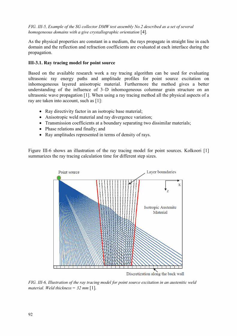
92
FIG. III-5, Example of the SG collector DMW test assembly No.2 described as a set of several homogeneous domains with a give crystallographic orientation [4].
As the physical properties are constant in a medium, the rays propagate in straight line in each domain and the reflection and refraction coefficients are evaluated at each interface during the propagation.
III-3.1. Ray tracing model for point source
Based on the available research work a ray tracing algorithm can be used for evaluating ultrasonic ray energy paths and amplitude profiles for point source excitation on inhomogeneous layered anisotropic material. Furthermore the method gives a better understanding of the influence of 3–D inhomogeneous columnar grain structure on an ultrasonic wave propagation [1]. When using a ray tracing method all the physical aspects of a ray are taken into account, such as [1]:
Ray directivity factor in an isotropic base material; Anisotropic weld material and ray divergence variation; Transmission coefficients at a boundary separating two dissimilar materials; Phase relations and finally; and Ray amplitudes represented in terms of density of rays.
Figure III-6 shows an illustration of the ray tracing model for point sources. Kolkoori [1] summarizes the ray tracing calculation time for different step sizes.
FIG. III-6, Illustration of the ray tracing model for point source excitation in an austenitic weld material. Weld thickness = 32 mm [1].

93
III-4. SIMULATION MODEL OF PHASED ARRAY TECHNIQUES FOR AN ARTIFICIAL DEFECT
In case of dissimilar metal welds, which have been already performed, based on known grain size and orientation, or in case of designed welds [5], based on software identified properties, optimal ultrasonic beam can be found by simulation of the inspection. The testing has been recently developed in the CIVA software in order to determine the index distances regarding the given orientation artificial defect analysis and the incident angles for longitudinal and transversal tests. Acoustic properties of materials in these joints were considered [6], as well as the effect of grain to the form of the ultrasonic beam, the probability of detection and determination of the location and orientation of the material discontinuities.
FIG. III-7, Simulation model of phased array techniques for an artificial defect.
a) Simulation b) Inspection
FIG. III-8, Simulated and real S-pictures.

94
III-5. CONCLUSIONS
By comparing the experimental and simulation tests results, conclusions can be drawn to quantitatively assess the contribution of phased array techniques to improved NDE performances of such parts, as well as the ability of simulation to help for design, optimization and interpretation of such inspections. The investigation of various PAUT systems will comfort confidence on NDE techniques and widen the feedback and knowledge of various partners. In addition to reporting of experimental and simulation tests, conclusions drawn from these studies and analysis of further development will be discussed for increased knowledge in the NDE and Nuclear communities.
Further information can be found in publication [7].
REFERENCES
[1] KOLKOORI, S., Quantitative Evaluation of Ultrasonic Wave Propagation in Inhomogeneous Anisotropic Austenitic Welds Using 3D Ray Tracing Method: Numerical and Experimental Validation, Berlin (2014).
[2] GRONG, O., Metallurgical Modelling of Welding, University Press, Cambridge (1997).
[3] OGILVY, J., Computerized ultrasonic ray tracing in austenitic steel, NDT Int. 18 2 (1985) 67.
[4] GARDAHAUT, A., LESKELA, E., MEHESZ, I., TAKACS, C., PAUT Modelling and Testing of Artificial Material Discontinuities, MAPAID D6.1.5, (2016).
[5] BEZI, Z., SZAVAI, S., OHMS, C., Numerical Simulation of Dissimilar Metal Welding, (2015).
[6] GARDAHAUT, A., LOURME, H., JENSON, F., LIN, S., NAGAI, M., Ultrasonic Wave Propagation in Dissimilar Metal Welds — Application of a Ray–Based Model and Comparison with Experimental Results, Prague, Czech Republic (2014).
[7] Modelling of Phased Array Ultrasonic Inspection of a Steam Generator Dissimilar Metal Weld, (2016) pp. 1015–1022.

95
ANNEX IV: REPAIR STRATEGIES BASED ON UT EXAMNINATIONS WITHIN WWER TYPE NPP’S
IV-1. REPAIR STRATEGIES BASED ON UT EXAMINATIONS WITHIN WWER TYPE NPP NDE ISSUES WITH SCC OCCURRENCE
IV-1.1. Summary:
This case study is devoted to several objectives. The first one is to show recent advanced UT implementation achievements and the history of the UT qualification activities on dissimilar metal welds (DMWs). There is described mechanized UT qualification for pulse echo technique performed in two phases and status of mechanized pulse echo and PAUT examination site feedback on WWER–440 type hot and cold SG collector DMWs at Dukovany NPP. The second goal is to present the approach how to ensure the readiness to repairs, repairs planning and effective changes of inspection intervals based on results of mechanized UT qualified examinations and knowledge of crack growth trends. The main focus is on WWER–440 type hot and cold SG collector DMWs at Dukovany NPP due to occurrence of corrosion degradation mechanisms including stress corrosion cracking. Destructive examination results with SCC occurrence in the repaired welds are presented together with advanced mechanized PAUT examination results.
IV-1.2. Introduction
This paper is devoted similarly like [1] to advanced UT implementation achievements and qualification activities on dissimilar metal welds (DMWs) in the Czech Republic. This paper contains a brief summary of recent advanced UT technology implementation based on ZIRCON UT phased array (PAUT) application with dual PAUT matrix search units and UT qualification achievements reached mainly for WWER–440 type Dukovany NPP with a focus on support of lifetime extension assessment and further Long Term Operation (LTO) of WWER type NPPs, partially for much younger WWER–1000 type Temelin NPP. The focus on DMWs and occurrence of specific degradation mechanisms in relation to extended lifetime assessment of appropriate components and piping systems with these welds has been initiated and supported by DMW SCC latest issues in the world (like 5 axial PWSCC at North Anna or circumferential SCC on WWER–440 type SG collector DMWs in Russia and Ukraine) and the State Office for Nuclear Safety (Czech Regulatory Body) requirements on provided License Renewal documentation related to the lifetime extension over 30 years of operation. Due to the fact that welding technology, partially base metals and mainly buttering material sensitive to SCC degradation is the same for WWER 440 SG collector DMWs and the other WWER–440 and WWER–1000 DMWs around the world, there is no surprise that a high level attention has been devoted to the potential occurrence of SCC type degradation at those NPPs especially when these plants are operated relatively close to or over 30 years. UT examinations analysed and performed during laboratory and qualification practical trials on the new test assembly have been completed from both austenitic and ferritic sides. Similarly, examinations and CIVA simulations have been conducted for both realistic conditions (with and without weld crown). These different search units have been also analysed using CIVA simulations and conducting examinations on available test assemblies.
IV-1.3. Recent UT qualifications of DMWs
2.1 Cold and Hot WWER–440 type SG collector DMWs at Dukovany NPP.

96
IV-1.4 Description of SG collector DMWs
Dissimilar metal welds at WWER type NPPs belong to the inspection areas of the highest concern in the last years. For WWER–440 type NPPs like Dukovany NPP the highest attention has been devoted to hot and cold steam generator DMWs (see Figure IV-1).
Hot and cold steam generator (SG) dissimilar metal welds:
two DMWs per SG; 12 DMWs per Unit; 48 DMWs at Dukovany NPP.
Were manufactured using the following materials:
Material of piping: 08Ch18N10T stainless steel (SS)
Material of nozzle: 22K carbon steel (CS)
Weld joint electrode: EA 400/10T.
FIG. IV-1: Simple drawing with cold and hot WWER–440 type SG collector DMW configuration.
IV-1.5. Pulse echo UT qualification
IV-1.5.1 The first phase of mechanized UT qualification
Mechanized UT qualification for pulse echo technique was performed in two phases. The first phase was completed in 1998 within PHARE project PH 1.02 / 94 as follows:
a) Completed qualification trial including inspection procedure (IP), technical justification (TJ) and practical trials (PT) where representatives of PHARE project PH 1.02 / 94 consortium (JRC Petten) were in the role of the Qualification Body;
CS 22K SS 321
DMW

97
b) Used simplified list of degradation mechanisms due to at that time worldwide unknown sensitivity of WWER type buttering material to SCC; and
c) Simple test block can be seen on Figure IV-2 (degradation mechanism only general mechanical fatigue, low number of defects (4), full scale 1:1 test assembly segment, no specific location of defects except the weld and weld bevels).
IV-2a) the test assembly from PHARE project IV-2b) national qualification test block
FIG. IV-2: Test assemblies for WWER 440 type SG collector DMW UT qualification.
IV-1.5.2. The second phase of mechanized UT qualification
The second phase of the pulse echo UT qualification was completed in 2011 with the following changes to the first phase:
a) Completed qualification of the same inspection procedure using the same equipment, manipulator and personnel;
b) Elaborated technical justification and performed practical trials under the supervision of the Czech Qualification Body; and
c) Practical trials conducted on a new full scale 1:1 test assembly (see Figure IV-2b) with 20 defects (7 realistic fatigue crack simulations and 13 artificial defects including fabrication lack of fusion type defects, but no stress corrosion cracking type defects) located in different positions.
Defects in the new test assembly (see Table 1) are located in the weld, along weld bevels and some specific defects are positioned on different interfaces (ferrite material to the 1st buttering layer, 1st buttering layer to 2nd buttering layer and 2nd buttering layer to the weld).
The distribution of defects in the new test assembly meets the requirements based on the knowledge before 2011 (general degradation mechanism mechanical/thermal fatigue, no specific aggressive degradation mechanism like SCC / PWSCC, service induced defect initiated from the inner surface, the maximal height up to 1/3 of the SG collector wall).
IV-1.6. PAUT qualification
Mechanized UT qualification for PAUT technique started in 2012 as follows:

98
(a) With PAUT inspection procedure also developed for dual search units (IMASONIC 1,5M32x2E64-15 with ZPA-ACC-W-DMW wedge and HQ Sonics 1,5 MHz, 64 elements (2rows of 32)) search unit with integrated wedge);
(b) And new calibration blocks (based on EPRI PDI experience); (c) Elaborated technical justification not yet completed for all dual probes and all
defect types; and (d) Performed laboratory practical trials on new full scale 1:1 test assembly segment
with 20 defects (7 realistic fatigue crack simulations and 13 artificial defects including fabrication lack of fusion type defects, but no stress corrosion cracking type defects) located in different positions.
FIG. IV-3: Laser scan image of the test assembly for WWER–440 type SG collector DMW UT qualification.
To improve our knowledge on the new test assembly shape a laser scanning of the test assembly was performed to avoid potential impact of different types of uncertainties due to test assembly ovality, weld crown and the weld crown vicinity. Figure IV-3: Laser scan image of the test assembly for WWER–440 type SG collector DMW UT qualification PAUT examinations analysed and performed during laboratory and qualification practical trials on the new test assembly were completed from both austenitic and ferritic sides. Similarly PAUT CIVA simulations were conducted for both realistic conditions (with and without weld crown) and from both sides. All the different search units were also analysed using CIVA simulations and conducting examinations on available test assemblies.
IV-2. SITE FEEDBACK FROM SG COLLECTOR DMWS ISI AT DUKOVANY NPP
IV-2.1. Corrosion degradation mechanisms occurrence
IV-2.1.1. Two examples of stress corrosion cracking indications detection
Circumferential stress corrosion cracks were detected and sized predominantly in the position along the interface of the buttering first layer to ferritic SG collector material by pulse echo traditional ultrasonic mechanized inspection and encoded phased array examination using either OMNISCAN or ZIRCON equipment with linear 16 elements search units and later with dual matrix phased array search units (see Figure 43).

99
Probe A, PAUT dual probe Probe B, PAUT dual probe
FIG. IV-4: Example 1 of SCC indication from WWER–440 type SG collector DMW before repair.
IV-2.2. Readiness to repairs of SG collector DMWs at Dukovany NPP
Readiness to repairs was influenced by the level of knowledge of degradation mechanisms and NDE issue root causes. Several factors like design failures, operational aspects and detailed knowledge of degradation mechanisms were of high importance. Very important role in root cause analysis was played by several operational aspects as strain loading up to app. 33% due to thermal expansion differences, non-standard corrosion medium (under corrosion deposits), corrosion medium in direct contact with the first layer of buttering sensitive to SCC and stress concentration factors on the crack tip. The mentioned degradation mechanisms were identified described and finally verified using also destructive examination results within the national Czech R&D project sponsored by CEZ.
Design failures, understood and considered only for the case of WWER 440 SG lifetime over 30 years, were caused mainly by the level of post welding heat treatment enabling carbon diffusion into the first layer of buttering and M23C6 on grain border and by applied non-stabilized steel with higher content of P and increased sensitivity to SCC Due to the fact that welding technology, partially base metals and mainly buttering material sensitive to SCC degradation is the same for WWER 440 SG collector DMWs and the other WWER–440 and WWER–1000 DMWs around the world, there is no surprise that a high level attention has been devoted to the potential occurrence of SCC type degradation at those NPPs especially when these plants are operated relatively close to or over 30 years. Implementation of Russian technology was conducted within the following phases:
1. Repair Technology was qualified in Czech Republic and implemented for Dukovany NPP by SKODA JS (known in the past as Skoda Nuclear Machinery)
2. Small lack of fusion (LOF) detected by UT in the weld root area of welding technology qualification test block
3. Challenge for CIVA simulation of LOF and comparison with real conventional and PAUT inspection results
4. Finally two SG hot collector DMWs repaired at Dukovany NPP at the end of 2012 (11/2012 – 12/2012) and in spring 2013 (04/2013).

100
Repairs were performed within acceptable period of time of approx. 20 days.
Near–far potential future candidates for SG collector repairs at Dukovany NPP will be determined based on Action plan of SG repair dependent on detected and sized corrosion type defect indications with SCC type degradation mechanism typical features. Typical determined features and parameters of SCC defect indications are
a) Inner surface breaking defect indication;
b) Location at or close to the interface carbon steel-the first layer of buttering; and
c) stress corrosion cracking spots at B-scans and defect indication echo dynamic behaviour.
IV-3. CONCLUSIONS
This case study is devoted to recent NDE issue related to WWER–440 type SG collector dissimilar welds. There is described and highlighted the whole UT qualification process both for conventional pulse echo UT and phased array UT techniques. The NDE issue leading to repairs of 2 hot SG collector dissimilar welds at Dukovany NPP is described from the point of degradation mechanisms identified, experimentally described and finally verified using also destructive examination results after the repairs within the national Czech R&D project sponsored by CEZ. From the point of lessons learnt there are summarized design failures and revealed operational aspects important for the initiation and propagation of revealed degradation mechanisms. Potential near future candidates, if any, for SG collector repairs at Dukovany NPP will be determined based on Action plan of SG repair dependent on detected and sized corrosion type defect indications with SCC type degradation mechanism typical features within in–service inspections. Readiness to repairs, repairs planning and effective changes of inspection intervals based on results of mechanized UT qualified examinations and knowledge of crack growth trends can be considered as the next objective.

101
ANNEX V: WELD OVERLAY OPERATING EXPERIENCE
V-1. WELD OVERLAY OPERATING EXPERIENCE
The use of weld overlays as a permanent repair technique has been in used for over two decades. Table V–1 provides an abbreviated listing of weld overlays applied in the United States by date, plant, component, and nozzle diameter. Temper bead welding was used in all recent overlays involving a nozzle made of low alloy steel.
TABLE V-1 WELD OVERLAY EXPERIENCE
Date Plant Component Nozzle
diameter (in)
2012 KKL N5 Nozzle 14.2
July–August 2010 Angra 1
PZR spray nozzle Safety/relief
nozzles PZR surge nozzles
4.5 6.63 12.75
December 2007 SCE/SONGS 2 PZR surge nozzle 12 November 2007 Duke/Oconee PZR spray nozzle
safety/relief nozzles PZR surge
nozzle
4 4.5 10
November 2007 APS/Palo Verde 3 PZR spray nozzle safety/relief
nozzles PZR surge nozzle
4 6
12 October 2007 SCE/SONGS 2 PZR surge nozzle 12 October 2007 Duke/Catawba 2 PZR spray nozzle
safety/relief nozzles PZR surge
nozzle
4 6
14 October 2007 PSEG/Hope Creek Recirc. Inlet
Nozzle 10 October 2007 TVA/Sequoyah 1 PZR spray nozzle
safety/relief nozzles PZR surge
nozzle
4 6
12 October 2007 Tai Power/Kuosheng
2 Recirc. Inlet
Nozzle 10 September 2007 Progress/Harris PZR spray nozzle
safety/relief nozzles PZR surge
nozzle
4 6
14 June 2007 APS/Palo Verde 1 PZR spray nozzle
safety/relief nozzles PZR surge
nozzle
4 6
12

102
Date Plant Component Nozzle
diameter (in)
May 2007 Entergy/ANO 1 PZR spray nozzle safety/relief
nozzles PZR surge nozzle
4 4.5
10 May 2007 Duke/Oconee 2 PZR spray nozzle
safety/relief nozzles PZR surge
nozzle
4 4.5
10 April 2007 Duke/McGuire 1 PZR spray nozzle
safety/relief nozzles PZR surge
nozzle
4 6
14 April 2007 STPNOC/South
Texas 2 PZR spray nozzle
safety/relief nozzles PZR surge
nozzle
6 6
16 March 2007 FPL/Duane Arnold Recirc Inlet
Nozzle 10 March 2007 TPC/Chin Shan Recirc Inlet
Nozzle 23 March 2007 Entergy/Pilgrim Recirc Inlet
Nozzle 10 December 2006 TVA/Sequoyah 2 PZR spray nozzle
safety/relief nozzles PZR surge
nozzle
4 6
14 November 2006 SCE/SONGS 3 PZR spray nozzle
safety/relief nozzles PZR surge
nozzle
5.1875 8
12.75
TABLE V-2 WELD OVERLAY EXPERIENCE (CONCLUDED)
Date Plant Component Nozzle
diameter (in)
November 2006 Duke/Catawba Unit 1 PZR spray nozzle 4 safety/relief nozzles 6 PZR surge nozzles 14
November 2006 Duke/Oconee Unit 1 PZR spray nozzle 4.5 safety/relief nozzles 4.5 PZR surge nozzles 10.875 HL Surge nozzle 10.75
October 2006 Duke/McGuire Unit 2 PZR spray nozzle 4 safety/relief nozzles 6

103
Date Plant Component Nozzle
diameter (in)
PZR surge nozzles 14 April 2006 FENOC/Davis Besse Hot leg drain nozzle 4
February 2006 SCE/SONGS Unit 2 PZR spray nozzle 8 safety/relief nozzles 6
November 2005 TPC/Kuosheng Unit2 Recirculation outlet nozzle 22
April 2004 PPL/Susquehanna Unit 1 Recirculation inlet nozzle 12 Recirculation outlet
nozzle 28 November 2003 AmerGen/TMI Unit 1 Surge line nozzle 11.5 October 2003 Entergy/Pilgrim Core spray nozzle 10
CRD return nozzle 5 October 2002 Exelon/Peach Bottom Core spray nozzle 10
Units 2&3 Recirculation outlet nozzle 28
CRD return nozzle 5 October 2002 AmerGen/Oyster Creek Recirculation outlet
nozzle 26 December 1999 FPL/Duane Arnold Recirculation inlet nozzle 12
June 1999 FENOC/Perry Feedwater nozzle 12 June 1998 CEG/Nine Mile Point Feedwater nozzle 12
Unit 2 March 1996 Progress/Brunswick Feedwater nozzle 12
Units 1&2 February 1996 Southern/Hatch Unit 1 Recirculation inlet nozzle 12 January 1991 Entergy/River Bend Feedwater nozzle 12 March 1986 Entergy/Vermont
Yankee Core spray nozzle
10 July-August 2010 Angra 1 PZR spray nozzle
Safety/relief nozzles PZR surge nozzles
114.3 168.3 323.9
Some plants outside the United States have also applied weld overlays although the operating experience is not as extensive. Korea Hydro and Nuclear Power (KHNP) successfully applied five weld overlays to Kori Unit 1 pressurizer dissimilar metal welds in the fall of 2009. This was the first application of weld overlays in Korea. Taiwan Power Company installed pre-emptive weld overlays on pressurizer DMWs at Maanshan Nuclear Power Plant. The result was 12 weld overlays with mock-ups beginning in 2008 and implementation finished in 2011. In addition to Maanshan, 3 stainless steel overlays and 1 DMW overlay was applied at Kuosheng in 2000 and 2010 respectively.
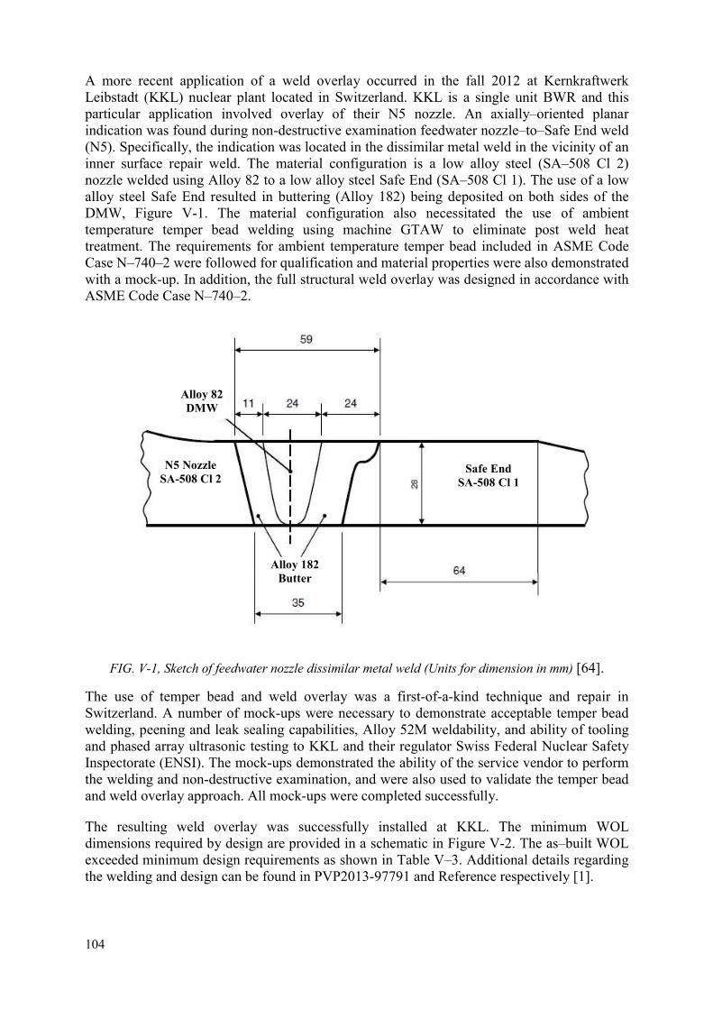
104
A more recent application of a weld overlay occurred in the fall 2012 at Kernkraftwerk Leibstadt (KKL) nuclear plant located in Switzerland. KKL is a single unit BWR and this particular application involved overlay of their N5 nozzle. An axially–oriented planar indication was found during non-destructive examination feedwater nozzle–to–Safe End weld (N5). Specifically, the indication was located in the dissimilar metal weld in the vicinity of an inner surface repair weld. The material configuration is a low alloy steel (SA–508 Cl 2) nozzle welded using Alloy 82 to a low alloy steel Safe End (SA–508 Cl 1). The use of a low alloy steel Safe End resulted in buttering (Alloy 182) being deposited on both sides of the DMW, Figure V-1. The material configuration also necessitated the use of ambient temperature temper bead welding using machine GTAW to eliminate post weld heat treatment. The requirements for ambient temperature temper bead included in ASME Code Case N–740–2 were followed for qualification and material properties were also demonstrated with a mock-up. In addition, the full structural weld overlay was designed in accordance with ASME Code Case N–740–2.
FIG. V-1, Sketch of feedwater nozzle dissimilar metal weld (Units for dimension in mm) [64].
The use of temper bead and weld overlay was a first-of-a-kind technique and repair in Switzerland. A number of mock-ups were necessary to demonstrate acceptable temper bead welding, peening and leak sealing capabilities, Alloy 52M weldability, and ability of tooling and phased array ultrasonic testing to KKL and their regulator Swiss Federal Nuclear Safety Inspectorate (ENSI). The mock-ups demonstrated the ability of the service vendor to perform the welding and non-destructive examination, and were also used to validate the temper bead and weld overlay approach. All mock-ups were completed successfully.
The resulting weld overlay was successfully installed at KKL. The minimum WOL dimensions required by design are provided in a schematic in Figure V-2. The as–built WOL exceeded minimum design requirements as shown in Table V–3. Additional details regarding the welding and design can be found in PVP2013-97791 and Reference respectively [1].
Alloy 182 Butter
N5 Nozzle SA-508 Cl 2
Safe End SA-508 Cl 1
Alloy 82 DMW

105
FIG. V-2 Schematic representation of KKL full structural weld overlay geometry, minimum required dimensions (mm)[1].
TABLE V-3 FULL STRUCTURAL WELD OVERLAY DIMENSION, MINIMUM AND AS–BUILT
Location Minimum Required As-Built Thickness
(mm) Nozzle Side 9.4 17.5
Safe End Side 9.4 17.5 Length (mm)
Nozzle Side 24.7 60.2 Safe End Side 30.5 66.3
V-2. MSIP-OPERATING EXPERIENCE
Mechanical Stress Improvement Process (MSIP) has been used successfully for many decades on both BWR and PWR plants as can be seen in Table V–4. There has also been operating experience using MSIP to mitigate weldments with pre-existing cracks as shown in Table Y. Significant amount of research has been done to demonstrate the effectiveness of MSIP which is publicly available for review. This information will be beneficial to plants looking to implement MSIP to mitigate dissimilar metal weldments susceptible to PWSCC.
TABLE V-4 MSIP EXPERIENCE
Utility Plant Year Pipe and
Fittings
Nozzles and Safe Ends
Total Notes
CECo Dresden 3 1986 50 2 52 CECo LaSalle 2 1987 25 29 54 3 CECo Quad Cities 1 1987 36 2 38 CP&L Brunswick 2 1988 0 15 15 1, 3 CECo Quad Cities 2 1988 43 4 47
Nuclenor Santa Maria de Garona 1988 24 0 24
OKG Aktiebolag Oskarshamn 2 1988 1 0 1 1

106
Utility Plant Year Pipe and
Fittings
Nozzles and Safe Ends
Total Notes
CP&L Brunswick 1 1988 0 10 10 3 CECo LaSalle 1 1988 15 15 30 CECo LaSalle 2 1988 8 0 8 CECo Dresden 2 1988 82 22 104 PECo Limerick 2 1988 2 16 18 Northeast Millstone 1 1989 0 22 22 3 Detroit Edison Fermi 2 1989 6 21 27 3 CECo Quad Cities 1 1990 28 12 40 CP&L Brunswick 2 1989/90 16 20 36 2 CECo Quad Cities 2 1990 30 14 44 2 Teollisuuden Voima TVO 1990 5 0 5
Niagara Mohawk Nine Mile Pt 2 1990 0 1 1 1, 3
Taiwan Power Kuosheng 2 1990 2 0 2 1 CP&L Brunswick 1 1990/91 10 24 34 2 Northeast Millstone 1 1991 34 9 43 Iberdola Cofrentes 1991 0 42 42 3 Boston Edison Pilgrim 1 1991 16 0 16 2
TABLE V-5 MSIP EXPERIENCE (CONCLUDED)
Utility Plant Year Pipe and
Fittings
Nozzles and Safe Ends
Total Notes
PECo Peach Bottom 3 1991 10 0 10
PECo Limerick 1 1992 0 7 7 1 Cleveland Elec. Perry 1 1992 0 27 27 1, 3
TVA Browns Ferry 3 1992 71 29 100 2
GPU Oyster Creek 1992 70 0 70 2 Georgia Power Hatch 1 1993 18 11 29 3
TVA Browns Ferry 2 1993 12 0 12 2
PP&L Susquehanna 1 1993 8 6 14
PECo Limerick 1 1994 4 14 18 Georgia Power Hatch 2 1994 0 18 18 3

107
Utility Plant Year Pipe and
Fittings
Nozzles and Safe Ends
Total Notes
PP&L Susquehanna 2 1994 7 5 12
GSU River Bend 1994 0 28 28 3 WPPSS WNP-2 1994 6 38 44 3 GPU Oyster Creek 1994 39 16 55
PP&L Susquehanna 1 1995 5 15 20
Consumer Pr. Palisades 1995 0 3 3 3, 4
PP&L Susquehanna 2 1995 5 16 21
North–east Util. Millstone 1 1995 13 0 13 North–east Util. Millstone 1 1996/97 71 0 71 PSE&G Hope Creek 1999 0 17 17 Exelon Quad Cities 1 2000 5 0 5 Amergen Oyster Creek 2000 17 0 17 Exelon Quad Cities 2 2002 4 0 4 SCE&G VC Summer 2002 0 2 2 1, 4 PSE&G Hope Creek 2003 0 2 2
Electrabel Tihange 2-TSP 2003 0 0 0 1, 4, 5 TOTALS 798 534 1,332
Notes: 1. Some weldments with pre–existing cracks. 2. Weldments for replacement piping made of SCC-resistant materials. 3. Treated weldments include Inconel 600 Safe Ends. 4. Application to PWRs.
5. Tihange 2-TSP may be rescheduled for spring 2005
TABLE V-5 MSIP TREATED WELDMENTS WITH PRE-EXISTING CRACKS (CONCLUDED) [2]
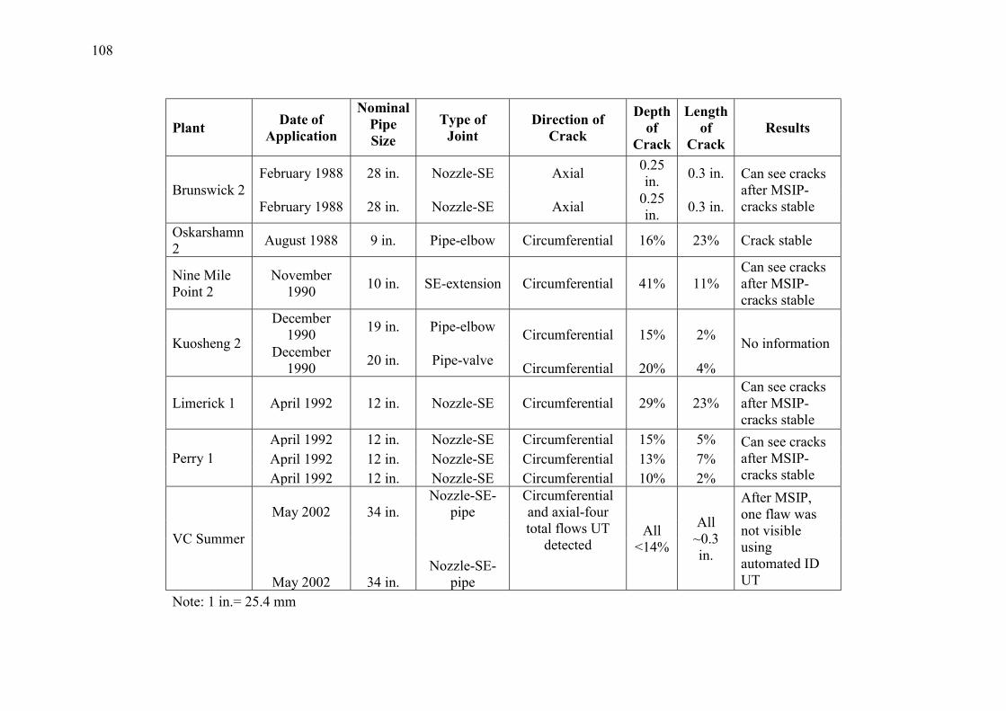
108
Plant Date of
Application
Nominal Pipe Size
Type of Joint
Direction of Crack
Depth of
Crack
Length of
Crack Results
Brunswick 2 February 1988 28 in. Nozzle-SE Axial
0.25 in.
0.3 in. Can see cracks after MSIP-cracks stable February 1988 28 in. Nozzle-SE Axial
0.25 in.
0.3 in.
Oskarshamn 2
August 1988 9 in. Pipe-elbow Circumferential 16% 23% Crack stable
Nine Mile Point 2
November 1990
10 in. SE-extension Circumferential 41% 11% Can see cracks after MSIP-cracks stable
Kuosheng 2
December 1990
19 in. Pipe-elbow Circumferential 15% 2%
No information December
1990 20 in. Pipe-valve
Circumferential 20% 4%
Limerick 1 April 1992 12 in. Nozzle-SE Circumferential 29% 23% Can see cracks after MSIP-cracks stable
Perry 1 April 1992 12 in. Nozzle-SE Circumferential 15% 5% Can see cracks
after MSIP-cracks stable
April 1992 12 in. Nozzle-SE Circumferential 13% 7% April 1992 12 in. Nozzle-SE Circumferential 10% 2%
VC Summer
May 2002 34 in. Nozzle-SE-
pipe Circumferential and axial-four total flows UT
detected All
<14%
All ~0.3 in.
After MSIP, one flaw was not visible using automated ID UT
May 2002 34 in. Nozzle-SE-
pipe Note: 1 in.= 25.4 mm

109
REFERENCES
[1] ENGEL, R., HELDT, J., KRAUSE, C., Design and Analysis of a Full Structural Weld Overlay for a Feedwater Nozzle-to-Safe End Dissimilar Metal Butt Weld, IASMiRT, San Francisco, CA (2013). [2] Materials Reliability Program: Program on Technology Innovation: An Evaluation of Surface Stress Improvement Technologies for PWSCC Mitigation of Alloy 600 Nuclear Components (MRP- 162), EPRI Palo Alto, CA, EPRI, Palo Alto, CA (2006)

111
CONTRIBUTORS TO DRAFTING AND REVIEW
Baliza, M.
Duchacek, P.
Efsing, P.
Fazekas, F.
Frederick, G.
Electronuclear, Brazil
CEZ, Temelin, Czech Republic
Ringhals AB, Sweden
HAEA, Hungary
EPRI, United States of America
Gaboyan, P.
Horacek, L.
Irimescu, C.
Khalid, M.
Kuusinen, P.
Metsamor, Armenia
ÚJV Řež, a. s., Czech Republic
CNE Cernavoda, Romania
PAEC, Pakistan
TVO, Finland
Liu, S.
Mlejnek, A.
Mohr, N.
Salles, C.
Saroj, P.
Szabolcs, S.
Viard, E.
York, C
Canadian Nuclear Safety Commission, Canada
CEZ, Dukovany, Czech Republic
EPRI, United States of America
CNEA, Argentina
Bhabha Atomic Research Centre, India
Bay Zoltan Nonprofit Ltd., Hungary
IRSN, France
IWE, Canada
Zettervall, T. SQC, Sweden
Consultants Meetings
Vienna, Austria: 10-13. November 2015, 12–15 April 2016, 8–10 October 2016, 2-4 September 2017
Technical Meeting
Vienna, Austria: 11-14. July 2017


ORDERING LOCALLYIn the following countries, IAEA priced publications may be purchased from the sources listed below or from major local booksellers.
Orders for unpriced publications should be made directly to the IAEA. The contact details are given at the end of this list.
CANADARenouf Publishing Co. Ltd22-1010 Polytek Street, Ottawa, ON K1J 9J1, CANADATelephone: +1 613 745 2665 Fax: +1 643 745 7660Email: [email protected] Web site: www.renoufbooks.com
Bernan / Rowman & Littlefield15200 NBN Way, Blue Ridge Summit, PA 17214, USATel: +1 800 462 6420 • Fax: +1 800 338 4550Email: [email protected] Web site: www.rowman.com/bernan
CZECH REPUBLICSuweco CZ, s.r.o.Sestupná 153/11, 162 00 Prague 6, CZECH REPUBLICTelephone: +420 242 459 205 Fax: +420 284 821 646Email: [email protected] Web site: www.suweco.cz
FRANCEForm-Edit5 rue Janssen, PO Box 25, 75921 Paris CEDEX, FRANCETelephone: +33 1 42 01 49 49 Fax: +33 1 42 01 90 90Email: [email protected] Web site: www.form-edit.com
GERMANYGoethe Buchhandlung Teubig GmbHSchweitzer FachinformationenWillstätterstrasse 15, 40549 Düsseldorf, GERMANYTelephone: +49 (0) 211 49 874 015 Fax: +49 (0) 211 49 874 28Email: [email protected] Web site: www.goethebuch.de
INDIAAllied Publishers1st Floor, Dubash House, 15, J.N. Heredi Marg, Ballard Estate, Mumbai 400001, INDIATelephone: +91 22 4212 6930/31/69 Fax: +91 22 2261 7928Email: [email protected] Web site: www.alliedpublishers.com
Bookwell3/79 Nirankari, Delhi 110009, INDIATelephone: +91 11 2760 1283/4536Email: [email protected] Web site: www.bookwellindia.com
@ No. 25

ITALYLibreria Scientifica “AEIOU”Via Vincenzo Maria Coronelli 6, 20146 Milan, ITALYTelephone: +39 02 48 95 45 52 Fax: +39 02 48 95 45 48Email: [email protected] Web site: www.libreriaaeiou.eu
JAPANMaruzen-Yushodo Co., Ltd10-10 Yotsuyasakamachi, Shinjuku-ku, Tokyo 160-0002, JAPANTelephone: +81 3 4335 9312 Fax: +81 3 4335 9364Email: [email protected] Web site: www.maruzen.co.jp
RUSSIAN FEDERATIONScientific and Engineering Centre for Nuclear and Radiation Safety107140, Moscow, Malaya Krasnoselskaya st. 2/8, bld. 5, RUSSIAN FEDERATIONTelephone: +7 499 264 00 03 Fax: +7 499 264 28 59Email: [email protected] Web site: www.secnrs.ru
UNITED STATES OF AMERICABernan / Rowman & Littlefield15200 NBN Way, Blue Ridge Summit, PA 17214, USATel: +1 800 462 6420 • Fax: +1 800 338 4550Email: [email protected] Web site: www.rowman.com/bernan
Renouf Publishing Co. Ltd812 Proctor Avenue, Ogdensburg, NY 13669-2205, USATelephone: +1 888 551 7470 Fax: +1 888 551 7471Email: [email protected] Web site: www.renoufbooks.com
Orders for both priced and unpriced publications may be addressed directly to:Marketing and Sales UnitInternational Atomic Energy AgencyVienna International Centre, PO Box 100, 1400 Vienna, AustriaTelephone: +43 1 2600 22529 or 22530 • Fax: +43 1 2600 29302 or +43 1 26007 22529Email: [email protected] • Web site: www.iaea.org/books 18
-03881

International Atomic Energy AgencyVienna
ISBN 978-92-0-105618-4ISSN 1011–4289
Dissimilar Metal Weld Inspection, Monitoring and Repair Approaches
@
IAEA-TECDOC-1852
IAEA-TECDOC-1852
IAEA TECDOC SERIES
Dissim
ilar Metal W
eld Inspection, Monitoring and Repair Approaches
IAEA-TECDOC-1852