iain blampied university portfolio
DESCRIPTION
ÂTRANSCRIPT

UNIVERSITY PORTFOLIOIAIN BLAMPIED
UNIVERSITY OF SYDNEYSEDIMENTARY - YEAR 5 - 2011
THEATRE OF EROSION - YEAR 5 - 2011
HYDE CYCLE CENTRE - YEAR 4 - 2010
UNIVERSITY OF PORTSMOUTHEMSWORTH ACTIVITY CENTRE - YEAR 3 - 2007
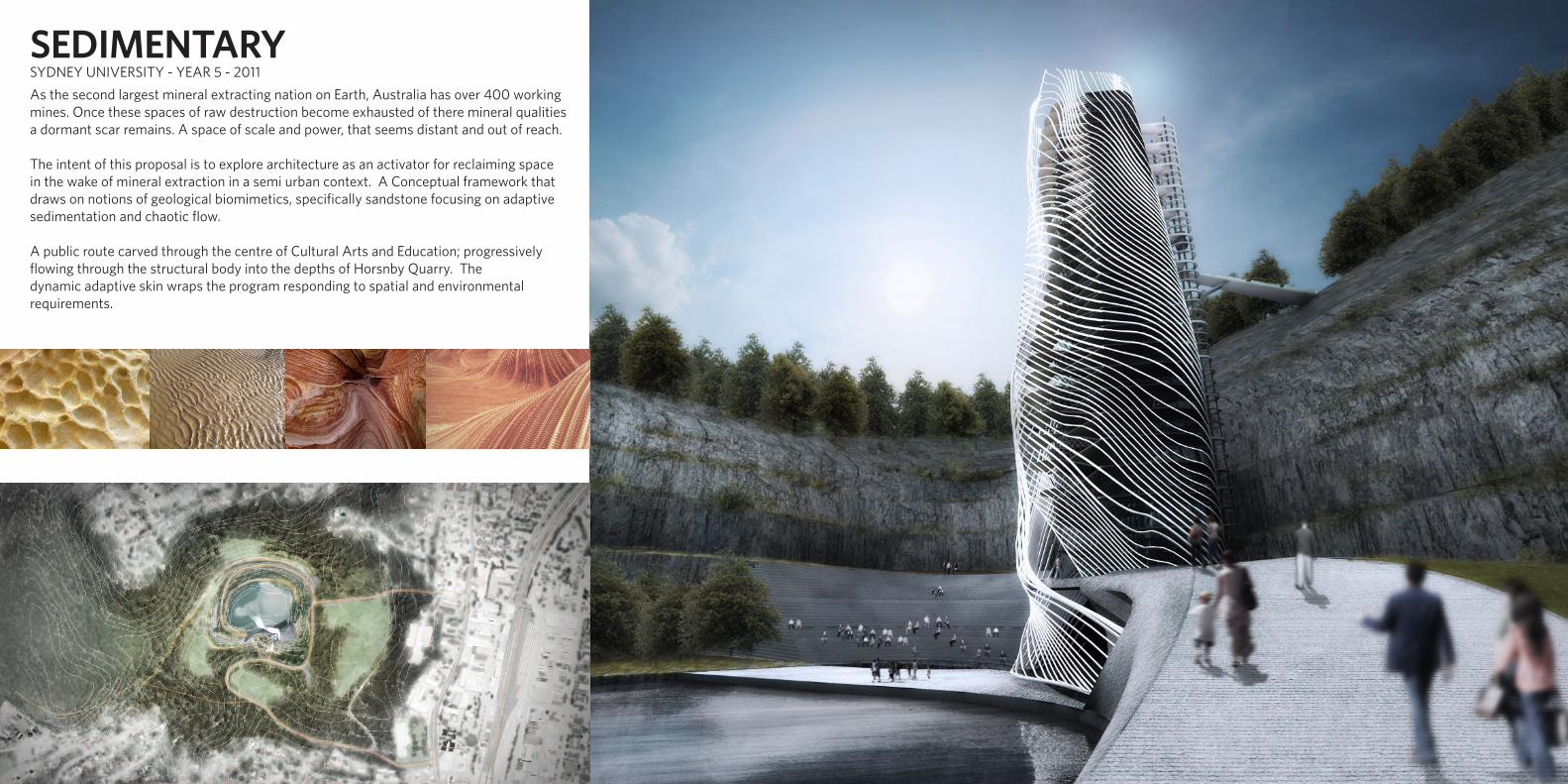
SEDIMENTARYAs the second largest mineral extracting nation on Earth, Australia has over 400 working mines. Once these spaces of raw destruction become exhausted of there mineral qualities a dormant scar remains. A space of scale and power, that seems distant and out of reach.
The intent of this proposal is to explore architecture as an activator for reclaiming space in the wake of mineral extraction in a semi urban context. A Conceptual framework that draws on notions of geological biomimetics, specifically sandstone focusing on adaptive sedimentation and chaotic flow.
A public route carved through the centre of Cultural Arts and Education; progressively flowing through the structural body into the depths of Horsnby Quarry. The dynamic adaptive skin wraps the program responding to spatial and environmental requirements.
SYDNEY UNIVERSITY - YEAR 5 - 2011

1 2
4 5
3
1. Entrance Bridge2. Lifts3. Public Ramp4. Entry Cafe5. Ticket office + Building information centre
In section a standard structural grid system denotes rigid space division and movement between levels.. A standard system uses columns and beams that have a primary role of structural stability
The Floor plates were fractured, forming a stronger visual link between levels. Breaking each floor plate into three created a set of progressive plateaus that lead to the level below.
Linking the plateaus with ramps increases the physical connection between levels. A natural hierarchy of levels began to form, the route down the building was carved out between the plateaus.
Linking alternate levels formed a line of connection between ramp surfaces this became a component for structural stability.
The flowing circulation is within the structure, forming two major circulation pathways, vertical (local) and horizontal (global) routes.
ENTRY LEVEL PLAN
SPATIAL CONNECTIVITY
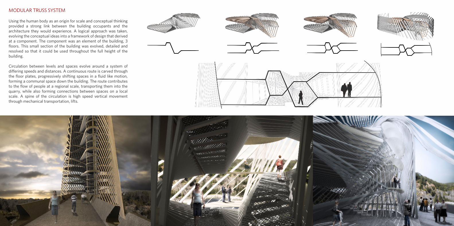
MODULAR TRUSS SYSTEM
Using the human body as an origin for scale and conceptual thinking provided a strong link between the building occupants and the architecture they would experience. A logical approach was taken, evolving the conceptual ideas into a framework of design that derived at a component. The component was an element of the building, 3 floors. This small section of the building was evolved, detailed and resolved so that it could be used throughout the full height of the building.
Circulation between levels and spaces evolve around a system of differing speeds and distances. A continuous route is carved through the floor plates, progressively shifting spaces in a fluid like motion, forming a communal space down the building. The route contributes to the flow of people at a regional scale, transporting them into the quarry, while also forming connections between spaces on a local scale. A spine of the circulation is high speed vertical movement through mechanical transportation, lifts.
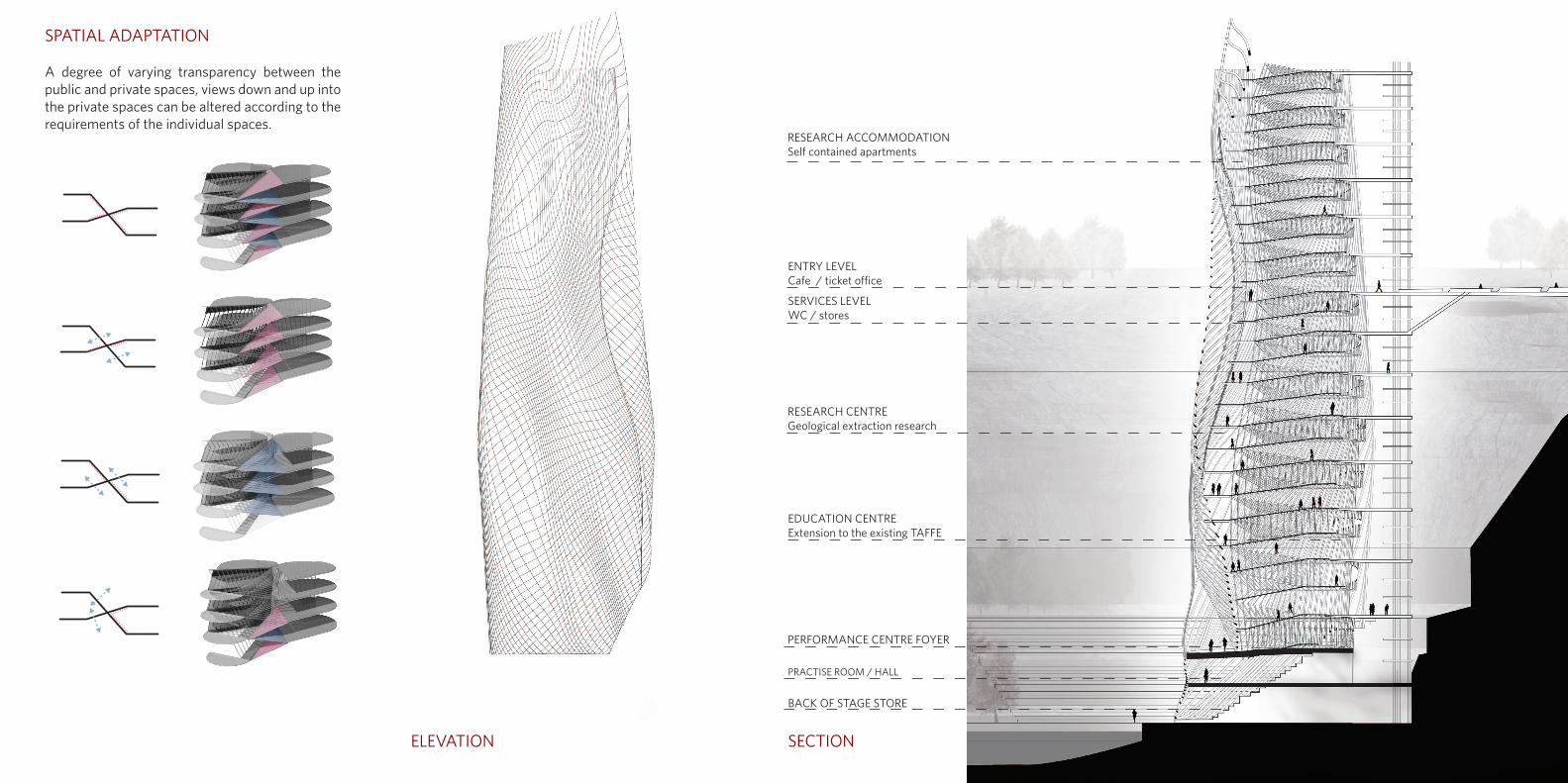
RESEARCH ACCOMMODATIONSelf contained apartments
ENTRY LEVELCafe / ticket office
SERVICES LEVELWC / stores
RESEARCH CENTREGeological extraction research
EDUCATION CENTREExtension to the existing TAFFE
PERFORMANCE CENTRE FOYER
PRACTISE ROOM / HALL
BACK OF STAGE STORE
A degree of varying transparency between the public and private spaces, views down and up into the private spaces can be altered according to the requirements of the individual spaces.
SPATIAL ADAPTATION
ELEVATION SECTION
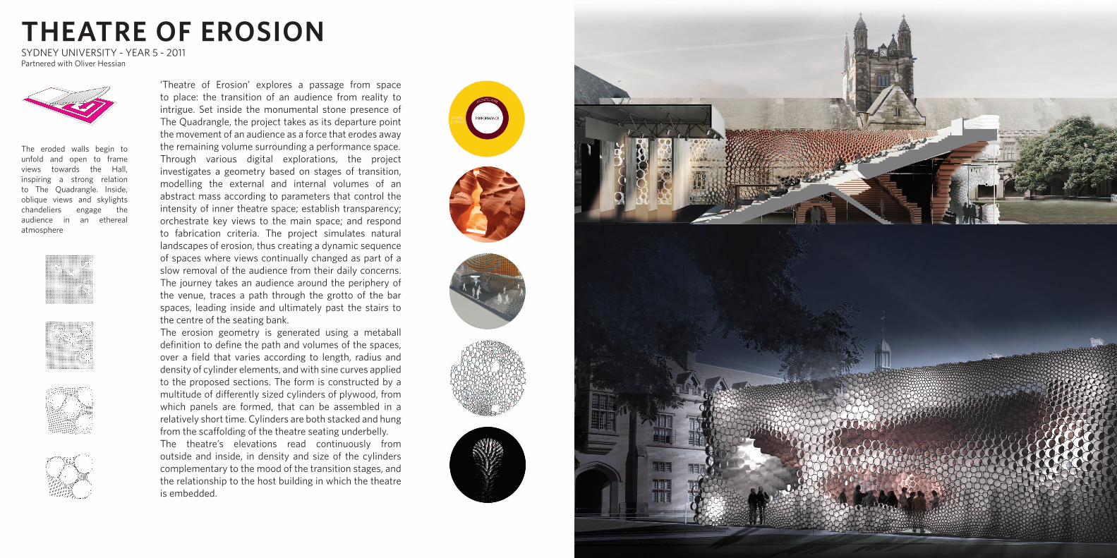
‘Theatre of Erosion’ explores a passage from space to place: the transition of an audience from reality to intrigue. Set inside the monumental stone presence of The Quadrangle, the project takes as its departure point the movement of an audience as a force that erodes away the remaining volume surrounding a performance space. Through various digital explorations, the project investigates a geometry based on stages of transition, modelling the external and internal volumes of an abstract mass according to parameters that control the intensity of inner theatre space; establish transparency; orchestrate key views to the main space; and respond to fabrication criteria. The project simulates natural landscapes of erosion, thus creating a dynamic sequence of spaces where views continually changed as part of a slow removal of the audience from their daily concerns. The journey takes an audience around the periphery of the venue, traces a path through the grotto of the bar spaces, leading inside and ultimately past the stairs to the centre of the seating bank.The erosion geometry is generated using a metaball definition to define the path and volumes of the spaces, over a field that varies according to length, radius and density of cylinder elements, and with sine curves applied to the proposed sections. The form is constructed by a multitude of differently sized cylinders of plywood, from which panels are formed, that can be assembled in a relatively short time. Cylinders are both stacked and hung from the scaffolding of the theatre seating underbelly. The theatre’s elevations read continuously from outside and inside, in density and size of the cylinders complementary to the mood of the transition stages, and the relationship to the host building in which the theatre is embedded.
The eroded walls begin to unfold and open to frame views towards the Hall, inspiring a strong relation to The Quadrangle. Inside, oblique views and skylights chandeliers engage the audience in an ethereal atmosphere
THEATRE OF EROSIONSYDNEY UNIVERSITY - YEAR 5 - 2011Partnered with Oliver Hessian
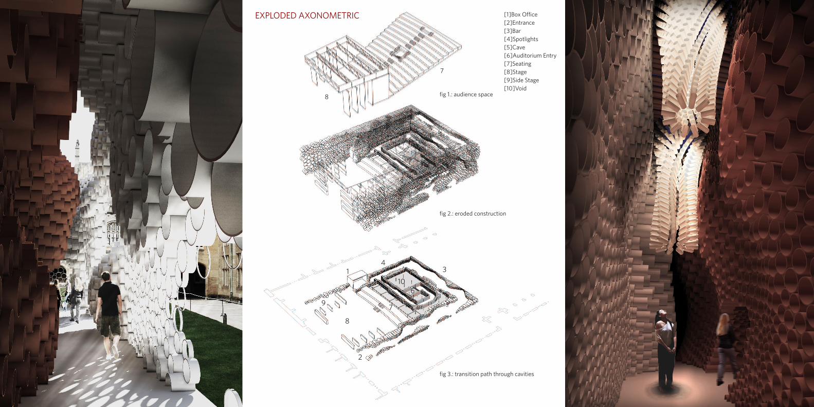
[1]Box Office [2]Entrance [3]Bar [4]Spotlights[5]Cave [6]Auditorium Entry[7]Seating[8]Stage [9]Side Stage [10]Void
1
2
34
56
7
8
9
10
7
fig 1.: audience space
fig 2.: eroded construction
fig 3.: transition path through cavities
8
EXPLODED AXONOMETRIC
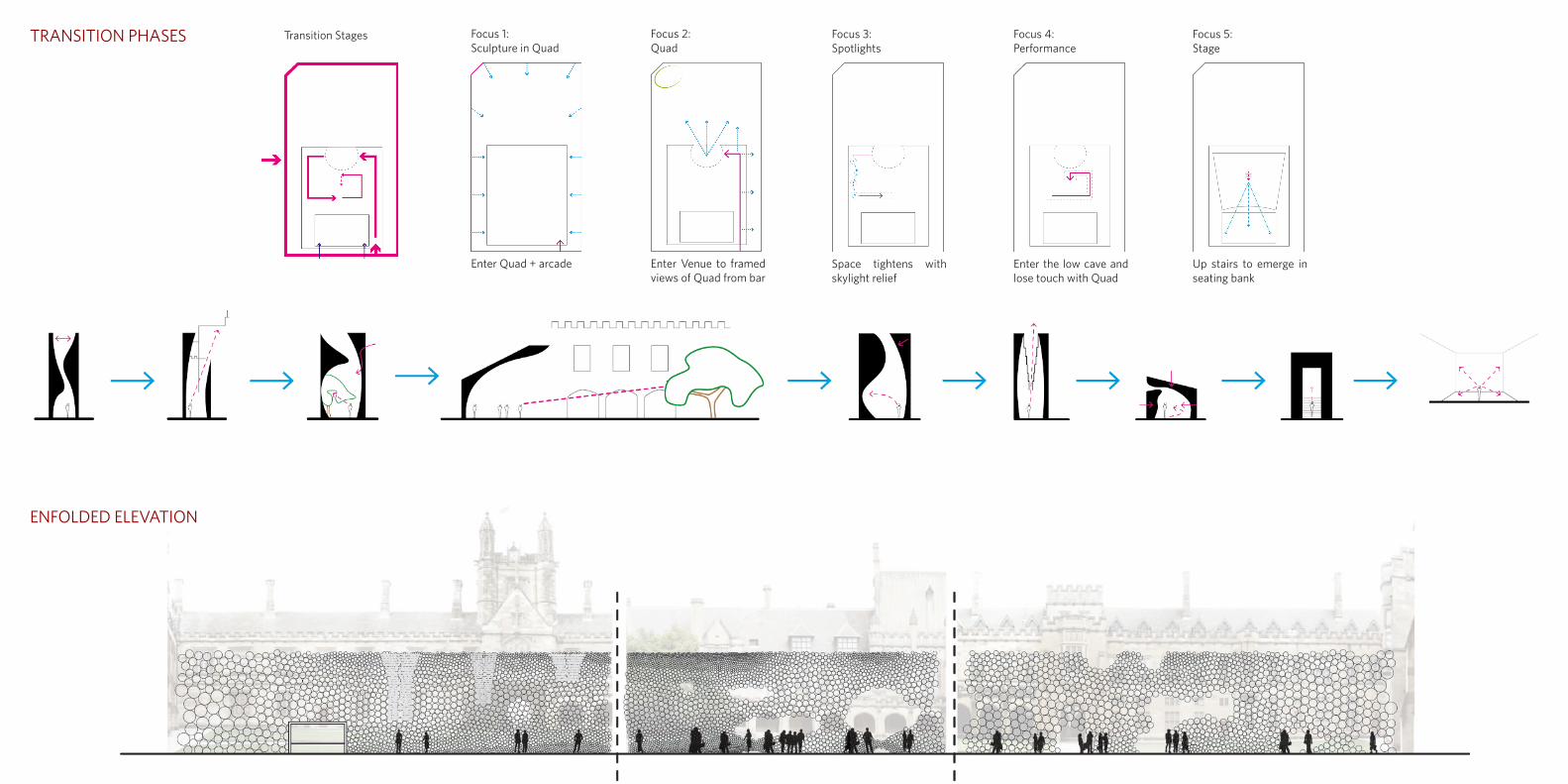
Transition Stages Focus 1: Sculpture in Quad
Enter Quad + arcade
Focus 2: Quad
Enter Venue to framed views of Quad from bar
Focus 3: Spotlights
Space tightens with skylight relief
Focus 4: Performance
Enter the low cave and lose touch with Quad
Focus 5: Stage
Up stairs to emerge in seating bank
TRANSITION PHASES
ENFOLDED ELEVATION

In order for the fabrication to be as straightforward as possible we have limited the cylinder radius to nine sizes. These could then be ordered in bulk at their standard length and cut to size for the panel assembly. These prefabricated panels would then be bolted together on site.
CONSTRUCTION DIAGRAM
SCHEME MODELS
YOUTOPIA EXHIBITION Photos by Kathrine Lu
BICYCLE HUB
Member of the bicycle hub
Daily commute Connect to bike, helmet on,
become one with bike and ride into city
Heavy exerciseArrive hot and sweaty
None member of bicycle hub
Occasional cyclistCausal expirence, slowly make
way into the city
Gentel exercise Arrive reasonably fresh
Tourist
Public transport walk into the city from
accommodation
Light exerciseArrive fresh
Hire bike+
equipmentStore bicycle short termStore bicycle long or
short term
Changing facilities, toilets, showers and
lockers
Eat + Drinkat cafe
Bicycle Repair centre
Walk to locations wthin city Cycle around the city
Return with bicycle
Guided toursBicycle route maps of the city
Bicycle repair facilities
Return for bicycle from store
Loby
Member Bike
Storage
Lockers
Changing Facilities
Retail and Bike RepairsTourist Bikes
Flexi Housing
Eat + Drink
Member Bike Storage Street
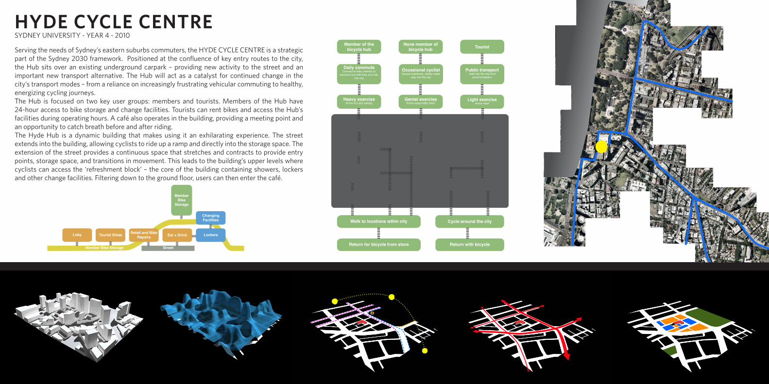
HYDE CYCLE CENTREServing the needs of Sydney’s eastern suburbs commuters, the HYDE CYCLE CENTRE is a strategic part of the Sydney 2030 framework. Positioned at the confluence of key entry routes to the city, the Hub sits over an existing underground carpark – providing new activity to the street and an important new transport alternative. The Hub will act as a catalyst for continued change in the city’s transport modes – from a reliance on increasingly frustrating vehicular commuting to healthy, energizing cycling journeys.The Hub is focused on two key user groups: members and tourists. Members of the Hub have 24-hour access to bike storage and change facilities. Tourists can rent bikes and access the Hub’s facilities during operating hours. A café also operates in the building, providing a meeting point and an opportunity to catch breath before and after riding.The Hyde Hub is a dynamic building that makes using it an exhilarating experience. The street extends into the building, allowing cyclists to ride up a ramp and directly into the storage space. The extension of the street provides a continuous space that stretches and contracts to provide entry points, storage space, and transitions in movement. This leads to the building’s upper levels where cyclists can access the ‘refreshment block’ – the core of the building containing showers, lockers and other change facilities. Filtering down to the ground floor, users can then enter the café.
SYDNEY UNIVERSITY - YEAR 4 - 2010

SKINSTORAGE TOWERSREFRESHMENT BLOCKRAMPSITE
NORTH ELEVATIONSCHEME MODELS
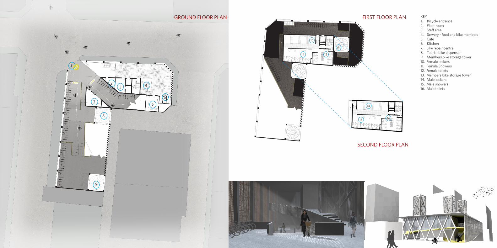
KEY1. Bicycle entrance 2. Plant room3. Staff area4. Servery - food and bike members 5. Cafe6. Kitchen 7. Bike repair centre8. Tourist bike dispenser9. Members bike storage tower 10. Female lockers11. Female Showers12. Female toilets13. Members bike storage tower14. Male lockers 15. Male showers16. Male toilets
1
4
5
6
2
8
3
10
11 12
13
14
15 16
SECOND FLOOR PLAN
7
9
FIRST FLOOR PLANGROUND FLOOR PLAN
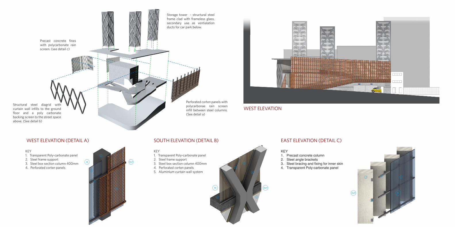
Precast concrete fines with polycarbonate rain screen. (see detail c)
Perforated corten panels with polycarbonae rain screen infill between steel columns. (See detail a)
Structural steel diagrid with curtain wall infills to the ground floor and a poly carbonate backing screen to the street space above. (See detail b)
Storage tower - structural steel frame clad with frameless glass, secondary use as ventialation ducts for car park below.
WEST ELEVATION (DETAIL A) SOUTH ELEVATION (DETAIL B) EAST ELEVATION (DETAIL C)
KEY1. Transparent Poly-carbonate panel 2. Steel frame support3. Steel box section column 400mm4. Perforated corten panels
KEY1. Precast concrete column 2. Steel angle brackets3. Steel bracing and fixing for inner skin4. Transparent Poly-carbonate panel
WEST ELEVATION
PHASE 1
Prepae existing site, remove all existing trees, shrubery, soft landscaping surfaces and steel fencing. Removing all existing render to reveal the bare faced structure to the existing car park. This is to provide a suitablely stripped site to allow construction to procceed whilest also for aesthetical reasons. Piles and transfer beams are to be positioned to insure the load of a new sturcutre is fully self supported and deos’t rely on the existing structure at all.
PHASE 2
Construct new base over the site in concrete, this will also form the beginning of the ramp on each side, untill the ramp becomes suspended using a different structural system. Along the west side of the site the proposed concrete will be set back from the existing to create a diffining edge between the two, whilst still creating an effect of drapping the proposed over the existing site.
PHASE 3
Form the second phase of insitu concrete construction, the two primay elements being the refresment block and the parting wall to the end of the west elevation.
PHASE 4
Construct the steel frame, this included the columns down the west elevation, the diagrid along the south elevation, the diagrid of the towers and the roof structure. The precast concrete fins to the rear elevations are also to be constructed during this phase. They are to arrive on site in short sections and bonded on site, they will be given lateral rigidity using the frame for the poly-carbonate inner skin, because the fins strength is in compression and not in a lateral direction. The steel frame is to be a simple mechano style system and is to have a sprayed painted finished.
PHASE 5
Construct the top section of the ramp, see detailed section. Steel beams are to be hung between the outer fame and the concrete structure of the refreshment block. This phase signifise the completion of the major structural elements of the building.
PHASE 6
This phase is the finishing stage. The west elevation is to have the corten panels hung to the outside of the columns and the poly-carbonate infiles fitted. The south elevation will have the poly-carbonate backing fixed above the ramp level and the curtain wall in installed below. Along the inner face of the pre cast concrtee fins a layer of ply carbonate is to be fixed creating a rain screen thought the building. The roof is to be finished and made water tight ensuring the correct falls are created. A glass skin is to be hung from the steel of the tower and the mechanism istalled inside.
WEST ELEVATION (DETAIL A) SOUTH ELEVATION (DETAIL B) EAST ELEVATION (DETAIL C)
1
3
4
5
2
KEY
1. Transparent Poly-carbonate panel
2. Steel frame support
3. Steel box section column 400mm
4. Perforated corten panels
KEY
1. Transparent Poly-carbonate panel
2. Steel frame support
3. Steel box section column 400mm
4. Perforated corten panels
5. Aluminium curtain wall system
KEY
1. Precast concrete column
2. Steel angle brackets
3. Steel bracing and fixing for inner skin
4. Transparent Poly-carbonate panel
CONSTRUCTION PROCCESS DIAGRAMS
4
3
2
1
3
2
1 4
OUTIN
OUTIN
INOUT
KEY1. Transparent Poly-carbonate panel 2. Steel frame support3. Steel box section column 400mm4. Perforated corten panels5. Aluminium curtain wall system
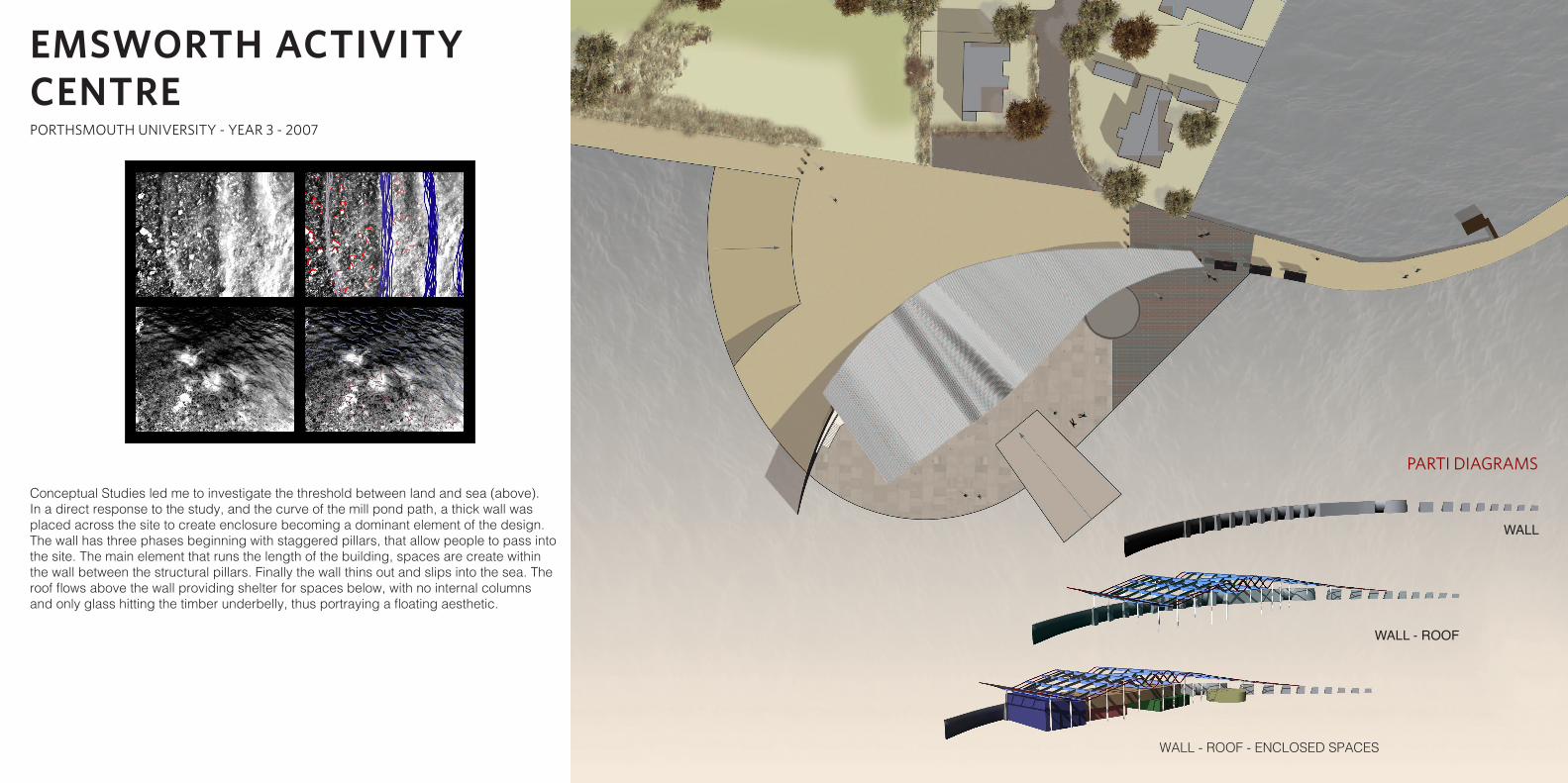
PARTI DIAGRAMS
WALL
WALL - ROOF
WALL - ROOF - ENCLOSED SPACES
Conceptual Studies led me to investigate the threshold between land and sea (above). In a direct response to the study, and the curve of the mill pond path, a thick wall was placed across the site to create enclosure becoming a dominant element of the design. The wall has three phases beginning with staggered pillars, that allow people to pass into the site. The main element that runs the length of the building, spaces are create within the wall between the structural pillars. Finally the wall thins out and slips into the sea. The roof flows above the wall providing shelter for spaces below, with no internal columns and only glass hitting the timber underbelly, thus portraying a floating aesthetic.
EMSWORTH ACTIVITY CENTREPORTHSMOUTH UNIVERSITY - YEAR 3 - 2007
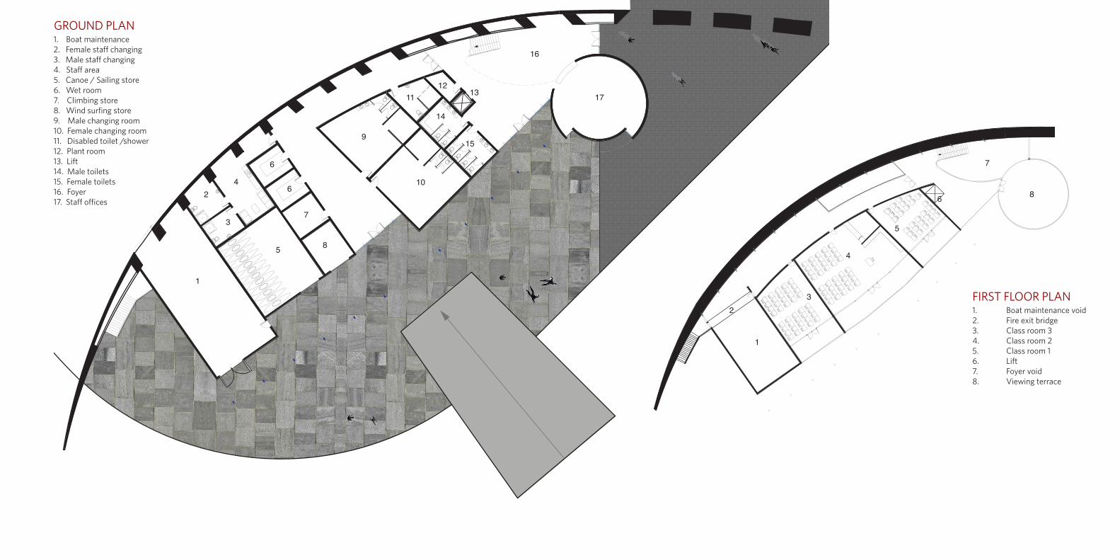
1. Boat maintenance void2. Fire exit bridge3. Class room 34. Class room 25. Class room 16. Lift7. Foyer void8. Viewing terrace
FIRST FLOOR PLAN
GROUND PLAN1. Boat maintenance2. Female staff changing 3. Male staff changing4. Staff area5. Canoe / Sailing store6. Wet room7. Climbing store8. Wind surfing store9. Male changing room 10. Female changing room 11. Disabled toilet /shower12. Plant room13. Lift14. Male toilets15. Female toilets16. Foyer17. Staff offices
1
2
3
4
5
6
6
7
8
9
10
11
14
15
1213
16
17
1
23
4
5
6
7
8

CONCEPTUAL SKETCHES
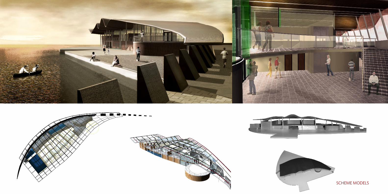
SCHEME MODELS