ibm 4331 processor systems channel characteristics description of the ibm 4331 processor channels...
TRANSCRIPT

Systems
GA33·1527·0 File No.4300·01
IBM 4331 Processor " "
Channel Characteristics

First Edition, April 1979
Information contained in this manual is subject to change from time to time. Any such change will be reported in subsequent revisions or through the System Library Subscription Service.
Requests for copies of IBM publications should be made to your IBM representative or to the IBM branch office serving your locality.
A form for reader's comments is provided at the back of the publicati~n. If the form has been removed, comments may be addressed to IBM Product Publications, Department 3179, Schoenaicher Strasse 220, 7030 Boeblingen/Wuertt., Federal Republic of Germany. IBM may use or distribute any of the information you supply in a~y way it believes appropriate without incurring any obligation whatever. You may, of course, continue to use th~ information you supply.
~ Copyright International Business Machines Corporation 1979
i

PREFACE
This manual desc~ibes how the effects of imposing loads on the channels of the IBM 4331 p~ocesso~ can be checked. The book is intended fo~ physical planning enginee~s and systems analysts who wish to check that a p~oposed configu~ation of input/output (I/O) devices will wo~k satisfacto~ily in the IBM 4331 p~ocesso~.
The fi~st section of the book desc~ibes the types of channels to which I/O devices can be connected, the theoretical data rates of the channels, and the possible effects of imposing heavy I/O 'loads on those channels. The effects conside~ed a~e: data over~un, loss of device pe~formance, channel inte~fe~ence with the IBM 4331 p~ocesso~, p~og~am ove~~un, and excessive channel utilization.
The second section gives the p~ocedu~es for testing data overrun on individual channels, on the integ~ated channel bus, and on the IBM 4331 processo~. The section also includes a desc~iption of how to assign prio~ities to devices on the byte multiplexer channel.
The thi~d section deals with inte~ference with the IBM 4331 processor that is caused by activities on the channels, and describes how the inte~ference can be assessed. Estimates fo~ the effects of this interfe~ence on system throughput a~e given and it is shown how to check for the possibility of p~ogram ove~~un.
The fou~th section desc~ibes channel inte~fe~ence between I/O devices and how it can be calculated. The concept of channel utilization is given. Examples in this section show how the block multiplexing concept and the rotational position sensing feature reduce channel utilization. In addition, the impact of channel utilization on I/O device access time is desc~ibed togethe~ with its estimated effect on system throughput.
The fifth section gives recommended channel p~ogramming
conventions. Test procedu~es in this manual assume that channel p~ograms have been prepared in accordance with these conventions.
Before using this manual, the reader should have a thorough unde~standing of input/output ope~ations fo~ the IBM 4331 processor as described in:
IBM 4331 processor Functional Characteristics GA33-1526 and IBM 4300 P~ocessor P~inciples of Operation, fo~ ECPS: VSE Mode, GA22-7070.
When testing for data overrun on the byte multiplexe~
channel, a special wo~ksheet is ~equi~ed: IBM 4331 Processor Channel Load Sum Worksheet; GA33-1532 (available in pads of 50).
ii IBM 4331 Processor Compatibility Featu~es

CONTENTS
GENERAL DESCRIPTION OF THE IBM 4331 PROCESSOR CHANNELS .. 1 Attachment Capabili ties. . . . . . . 1 Effect Of Channel Loading. . 3
TESTS FOR CHANNEL DATA OVERRUNS. General. ..... . Test Of Individual Channels. Test Of The Integrated Channel Test for Processor Overrun .
Internal Priorities ..
Bus .
Priorities on Byte Multiplexer Channel . Method of Overrun Calculation. Data Overrun Test procedure.
231X On BMPX Overrun Considerations •.
4
· 4 . •• 5
· 6 · 12 .12 .13 • 18 .23 .30
I/O INTERFERENCE WITH PROCESSOR. .31 Channel interference timings. .31 Calculation of I/O Interference with the processor. .36
Interference due to Channel Activities in the processor.36 Interference due to I/O Utilization of Main Memory. .39
Effects of I/O Interfering with the processor. . . .42 Effect of I/O Interference on System Throughput. . .. 42 The Effect of I/O Interference on Program Overrun. .42
ChANNEL INTERFERENCE BETWEEN I/O DEVICES Calculation Of Channel Utilization .
Procedure for Tape Devices . . . . . Procedure for Direct Access Storage Devices.
Impact Of Channel Utilization On I/O Access Time . Effect Of Channel Contention On System Throughput.
· .45 .45 .45
• • • 48 .53
· .55
IMPLICIT ASSUMPTIONS . . . . . Channel Programming Conventions.
. . . . .56
IMMEDIATE OPERATIONS . . DATA CHAINING. CHAINABLE COMMANDS .
APPENDIX A.CHANNEL EVALUATION FACTORS FOR DEVICES ATTACHED TO BMPX AND DASD/MAGNETIC TAPE ADAPTERS.
· .56 .56
· .56 . . . .57
• • A 1
APPENDIX B. BYTE MULTIPLEXER DEVICES CHANNEL EVALUATION FACTORS . • • B 1
APPENDIX C. COMMUNICATIONS ADAPTER CHANNEL EVALUATION FACTORS . Cl
APPENDIX D. IBM 2701 DATA ADAPTER UNIT: PRIORITY ASSIGNMENT AND CHANNEL EVALUATION FACTORS . . . . . .D 1
How to Assign Priority Position of a 2701 .. • • • D 1 How to Enter 2701 Priority Information on Load Sum
Worksheet . . . . . . . . . . . . . .D2 How to Obtain Channel Evaluation Factores for Each 2701
Communication Line. . . . . . . . .D2
iii

APPENDIX E. IBM 2702 TRANSMISSION CONTROL: PRIORITY ASSIGNMENT AND CHANNEL EVALUATION FACTORS . . . . . . . . E 1
PROCEDURE WHEN TERMINAL CONTROLS AND SPEEDS ARE ALIKE ... E2 PROCEDURE WHEN TERMINAL CONTROLS AND SPEEDS ARE DIFFERENT.E2
How to Assign Priority Position of a 2702 • ••..... E2 How to Obtain Channel Evaluation Factors of a 2702 ... E3
APPENDIX F. IBM 2703 TRANSMISSION CONTROL: PRIORITY ASSIGNMENT AND CHANNEL EVALUATION FACTORS ........ F1
iv IBM 4331 Processor Compatibility Features


GENERAL DESCRIPTION OF THE IBM 4331 PROCESSOR CHANNELS
ATTACHMENT CAPABILITIES
Input/Output (I/O) devices can be connected to the IBM 4331 processor on the following standard channels:
- BYTE MULTIPLEXER CHANNEL (27 UNSHARED SUaCHANNELS +4 SHARED) - BLOCK MULTIPLEXER CHANNEL (32 UNSHARED SUBCHANNELS +8 SHARED)
The block multiplexer channel appears as selector channel to those devices that do not block multiplex.
In addition, eertain I/O devices can be connected directly, by using the following adapters instead of the usual channel and control unit combination:
1.) DASD Adapter - for connecting the following series of disk devices:
- 3310 - 3370 - 3340
(up to 4 strings, max. 4 devices/string) (up to 4 strings, max. 8 devices/,string) (up to 2 strings, max. 8 devices/string)
2.) MAGNETIC-TAPE Adapter - for connecting up to 6 IBM 8809 tape drives.
3.) Communications Adapter (CA) - for connecting up to eight Communication lines with the following rates: BSC/SDLC: 60 - 64000 BITS/SEC S/S 75 - 1200 BITS/SEC One 64000 BIT/SEC line is exclusive to all other lines
4.) Bus-to-Bus Adapter 1 (BBA-1) - for connecting one 5424 Multifunction card Unit
5.> Bus-to-Bus Adapter 2 (BBA-2) - for connecting local terminals and printers.
- IBM 3278-2A operator console - IBM 3278-2 keyboard/display - IBM 3287 terminal printer 80/120 cps - IBM 3289-4 line printer 155/400 LPM - ~BM 3262-1 line printer 600 LPM - user diskette
A maximum of 15 devices plus operator console can be attached, two of which can be line printers.
General Descriptio~
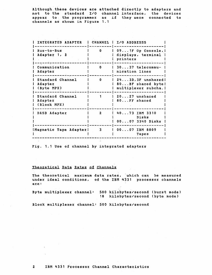
Although these devices are attached directly to adapters and not to the standard I/O channel interface, the devices appear to- the programmer as if they were connected to channels as shown in Figure 1.1
I 1
INTEGRATED ADAPTER 'CHANNEL
Bus-to-Bus 0 Adaptei: 1, 2
--~---~~------------- ---------Communication 0 Adapter
-~--~--~---~--~------ ~--------standard Channel 0 Adapter (Byte MPX)
-~~-~---------------- ---------standard Channel Adapter (Block MPX)
DASD Adapter 2
1--------------------- ---------IMagnetic Tape Adapter 3 I
I/O ADDRESSS
09 ... 1F Op Console, displays, terminal printers
30 ... 37 telecommunication lines
24 ... 3D,3F unshared 80. ~ .BF shared byte multiplexer subcha.
20 ... 27 unshared 80 ... FF shared
40 ... 73 IBM 3310 Disks
00 ... 07 3340 Disks
00 ... 07 IBM 8809 Tapes
Fig. 1.1 Use of channel by integrated adapters
Theoretical Data Rates of Channels
The theoretical maximum data rate~, 'which can be measured under ideal conditions, of the IBM 4331 processor channels are:
Byte multiplexer channel: 500 kilobytes/second (burst mode) 18 kilobytes/second (byte mode)
Block multiplexer dhannel.: 500 kilobytes/second
2 IBM 4331 Proeessor Channel Characteristics

EFFECT OF CHANNEL LOADING
If the channels of the IBM 4331 p~ocesso~ a~e too heavily loaded, that is, if the p~ocesso~ attempts to qommunicate simultaneously with too many devices that have high data ~ates, the following effects can occu~:
- Unbuffe~ed I/O devices may lose data; this is called data ove~~un.Data ove~run occu~s when a channel does not accept 0% t~ansfe~ data within the requi~ed time limits. This data loss may occur if the t~tal channel activity that is sta~ted by the p~og~am exceeds the channel capabilities. The possibility of ' data over~un can be checked as desc~ibed in the section 'Tests for Channel Data Ove~~uns'.
- Processo~ pe~fo~mance may be ~educed. This occu~s if channel activities interfe~e with processor ope~ations and effectively cause the processing of p~ocessor inst~uctions to be slowed down. The duration of inter£e~ence caused by channel activities is given in section 'I/O Inte~fe~ence with processo~'. The effect of this I/O inte~fe~ence on system throughput is outlined in section 'effect of I/O interfe~ence on system throughput'.
Certain real-time devices may not receive service from the p~ogram fast enough to p~event inco~rect device operation; this effect is called program ove~~un and is described in section 'effect of I/O inte~ference p~ogram ove~run'.
2ueues may develop fo~ tasks that ~equire channel thus leading to loss of th~oughput; see the 'Channel Inte~fe~ence between I/O Devices'.
se~vice,
section
Because of these effects, it is desi~able that the loading of a pa~ticular configu~ation of I/O devices be checked, using the procedu~es in this manual, during the physical planning phase of a syst~m installation. These procedures will dete~mine, in most cases, whethe~ system ope~ation will be satisfacto~y~; More detailed inve~tigation may be necessa~y for configurations that appea~ to exceed the IBM 4331 processo~ input/output capabilities.
The tests assume the worst-case situation that is likely to occur in' p~actice; that is, one in 'which the most demanding devices in'theconfig~ration all make thei~ heaviest demands on the channels simultaneously. Such a situation may not occu~ fr~quently, but it is the situation that the p~ocedures'in this manual place unde~ test.
The tests also assume that the channel p~ograms are w~itten in accordance with the ~ules'given later in the section, 'Channel P~Qgramming Conventions'.
Data Overruns 3

TESTS FOR CHANNEL DATA OVERRUNS
GENERAL
This section describes how the channels can be tested for data overrun. The test procedure involves three basic steps.
The first step is a check on the data rates of the ind~vidual I/O devices to find out whether any exceeds the maximum allowable data rate of the channel to which it is connected.
The second step consists in finding the worst case read-to-write ratios which in turn leads to the maximum allowable d~ta rate on the integrated channel bus which multiplexes the data traffic from all channels.
The finai and most critical test for data overrun uses the channel loading factors from the Appendix. The addition of the applicable loading factors in priority sequence can be done on a "channei load sum work sheet" and the result will show overrun hazard if the sum amounts to 100 or above.
The validity of the final step depends on a number of assumptions whi~h are explainded in the Appendix. These assumptions include the expectation that certain loops (e.g. search-TIC-search, sense-TIC-sense, etc) are avoided as well as other hazardous techniques (e.g. lon~ chains of immediate or no-op commands). It is especially assumed that the channel programming conventions listed in section 'implicit assumptions' are adhered to.
If actual system behavior is worse than implied by the assumptions, freedom from overrun cannot be predicted with certainty. If, on the other hand, actual system behavior is better than implied by the assum~tions, the system may still be overrun-free even when calculations indicate otherwise. In this case, special investigation may be necessary.
4 IBM 4331 Processor Channel Characteristics

TEST Ql INDIVIDUAL CHANNELS
Figu~e 2.1 shows the maximum possible data rates fo~ each individual channel attached to the p~oceSSOE. The individual data ~ates a~e limited by the design of each channel, that is, by its inteEnal micro code and ha~dwa~e structure. Obviously none of the maximum data rates must ever be exceeded otherwise immediate data overrun is incu~red.
The channels composed of Communications Adapter, Bus-to-Bus Adapter, DASD AdapteE and Magnetic Tape Adapte~ are customized to accomodate all I/O device combinations within the constraints of the IBM 4331 processor configurator without causing data overEun. The byte multiplexer channel and the block multiplexer channel are capable of transfe~~ing data at a maximum Eate of 500 kilobytes pe~ sec in hurst mode. Input/output devices which t~ansfer data at a higheE rate cannot be connected to these channels.
The byte multiplexer channel, when operating in single byte mode is capable of transferri~g data at a rate of 18 Kilobytes per second. The maximum data Eates for channels and di~ect attachments a~e shown below:
IIlocklDASD IByte MPX ICA IMagnet IIBA 1,2 I I MPX IAdaptlBurst/Bytelup to ITape IMFCU, I I 1 I Mode 18 linesIAdapterIDispl, .. 1
------------1-----1-----1----------1-------1-------1--------1 CS Prio~i ty 1 1 1 2 1 3 1 1 4 I 5 1 ------------1-----1-----1----------1-------1-------1--------1 KB/sec 1 500 1 18591 500/18 1 8 1 160 1 416 1
Note: The CA does not use the cycle steal facility. Only a single line can ope~ate at 64 kilo bits per sec = 8 Kilobytes pe~ sec.
riguEe 2.1: Channel Data Rates
Data Ove~~uns 5

TEST OF THE INTEGRATED CHANNEL BUS
When the individual channels have been ve~ified to cause no data over~un among thei~ own devices, the common inte~face between these channels and the sto~age must be tested fb~ ove~~un. This inte~face is ~efe~~ed to in the following sections as "IC-bus'.
The data t~ansfe~ p~io~ities on the IC-bus a~e as follows:
1. Block Multiplexer Channel (BMPX)
2. DASD Adapter
3. Byte Multiplexe~ Channel (MPX)
4. Magnetic Tape Adapter
5. Bus-To-Bus Adapte~ 1,2 (BBA P~inters, Diskettes)
1 , 2 ) (Local Displays,
If the processo~ is in t~ap level ~ 4, the BBA 1, 2 data t~ansfer on the IC bus is stopped. P~ocesso~ inte~nal
p~io~ities a~e ~efe~~ed to in the following sections as 't~ap level'. Fo~ details of these t~ap level p~io~ities see sectio~ 'internal p~io~ities'.
"The maximum unidi~ectional datCi t.kans£e~ ~ates a~e 3.67 "-"'Megal)-yt~~'''~ec fo~ sequential I/O w~i"te'-' ope~ations, and 3~ 33
MB1sec fo~ sequential I/O ~ead ope~ations. The~ui:es include a deg~adation which is caused by the sto~age ~ef~esh inte~fe~ence.
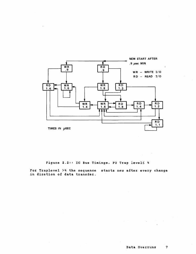
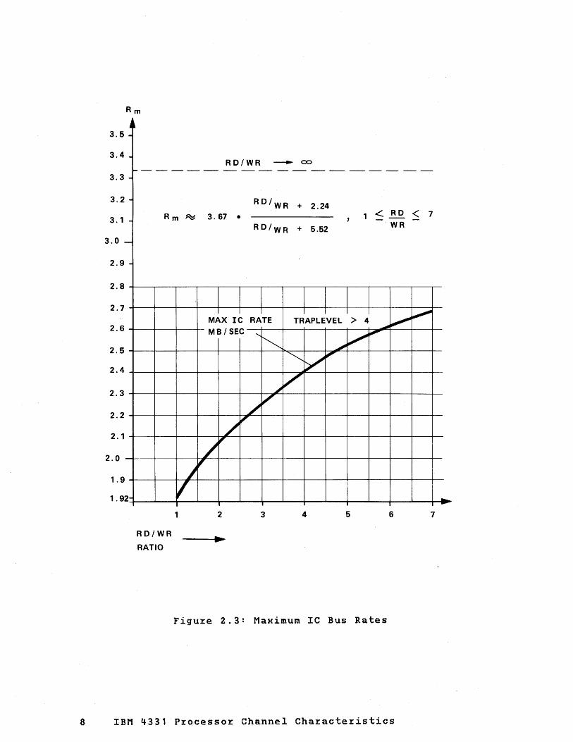
Howeve~, such maximum data ~ates can ~a~ely be achieved because the mo~e ~ealistic case is one whe~e ~ead and write ope~ations alternate frequently. The IC timings fo~ va~ious ~ead/write sequences are shown in figu~e 2.2. Based on these times, the maximum aggregate Ie-data ~ates are computed as a function of the worst case ~ead-to-write ~atio that can be expected. The cu~ves shown in figure 2.3 apply to the c~itical case whe~e the p~ocesso~ ope~ates in a t~ap level highe~ than level 4, in which case the p~ocesso~ gets cont~ol fo~ an ave~age of 0.9 usec each time the IC-bus t~affic changes from ~ead to write.
6 IBM 4331 P~ocessor Channel Characte~istics
TIMES IN jJSEC
NEW START AFTER
.9 )Jsec MIN
WR - WRITE I/O
RD - READ t/O
Figure 2.2:: Ie Bus Timings, PU Trap level~ 4
For Traplevel >4 the sequence starts new after every change in diretion of data transfer.
Data Overruns 7
Rm
H 3.5 -3.4
RD/WR -.... ex::> ------ - -- --- ---- ------ ----
3.3 -3.2 -3.1 -
3.0 -2.9 -
2.8
2.7
2.6
2.5
2.4
2.3
2.2
2.1
2.0
1.9
1.9 2-
Rm ~
RD/WR
RATIO
I V 1
RD/WR + 2.24 3.67 • 1 < RD , -
RD/WR + 5.52 WR
I I I I I I MAX IC RATE TRAPLEVEL > 4 ~ MB / SEC
~
'~ ~ ~
~
~ V ~
~ V
/ V
/ ~
/ " ,
2 3 4 5 6
Figure 2.3: Maximum IC Bus Rates
8 IBM 4331 Processor Channel Characteristics
< 7 -
"",
7 -..

The gene~al method fo~ assessing Ie-bus ove~~un is to use figu~e 2.3 in the following way:
1. List the maximum data ~ates Ri~ i~1 ... 4 that can occu~ on BMPX, DASD Adapte~, Magnetic Tape Adapte~, and on MPX due to bu~st mode devices.
2. Divide the ~ates Ri into two classes and fo~m the sum of the ~ates within each class with the intent to make the ~atio between the sums in both classes as close to 1 as possible, but without becoming smalle~ than 1.
3. The ~atio obtained in the p~eceding step ~ep~esents the wo~st case ~ead-to-w~ite ~atio that can be expected with the given configuration~ Use this ~atio to ente~ figu~e 2.3 on the abscissa (X-axis), then get the maximum allowable Ie-bus data rate from the o~dinate (y-axis).
4. If the Ie-bus data ~ate found is smaller than the sum of all rates Ri, then the planned configu~ation has a potential overrun hazard due to Ie-bus inte~fe~ence.
A simple~, mo~e st~aight-fo~ward method can be used when one adapte~ has a data ~ate which is la~ger than the data ~ates summed up f~om all ~emaining adapters. This situation is quite often encountered, especially with high speed disk storage devices such as IBM 3310 and IBM 3370. Figu~e 2.4 shows the maximum allowable data rates that remain available on each adapte~ when high speed disk sto~age devices are connected.
Type of Disk I If: data rate on Then: Max allowablel on DASD adaptl DASD adapte~ data ~ates on all I
I 1 other adapters is: 1 -------------1------------------1--------------------1
3370 1 1859 (KB/sec) 1 500 (KB/sec) 1 3310 1 1031 " I 850" 1 3340 1 885" I 960" 1
Figure 2.4: Maximum allowable data rates for unbuffered burst mode devices on all channels, and buffe~ed devices on block multiplexer channel and byte multiplexe~ channel, if the Magnetic Tape Adapter has tapes attached.
Data Overruns 9

For other 'predetermined' rates Rp allowable'remaining' rate Rr can be found following non-linear equation:
Rp+Rr=Rm(RJ:)
the maximum by solving the
wheJ:e Rm is the maximum allowable data J:ate given in figuze 2.3 as a funotion of the read-to-write ratio (RD/WR).
The solution to the equati~n can be £ound by va~ying Rr until Rm (RD/WR) =Rm (Rp/Rr~. is equal to Rp+Rr.
By app~oKimating ,~with a simple fiJ:st oJ:der fractional polynomi~l it.was p~ssible to solve above equation in closed form. The J:esult is shown in Fi~ure' 2.5, giving RJ: as a function of Rp. '
The maximum allowable data rates in Figure 2.4 apply to the qase wh~J:e the prdqe~or operates at a tJ:aplevel highei than 4, which means heayy cyel. steal data transfer and~haining activity. The· rate~ clearly show that an 3370 DASD opeiating together with a 3420~4 magnetic tape unit (data rate 470 KB/sec) will not allow any additional burst mode data tiansfeJ: from eitheJ: a direct attached IBM 8809 tape or tape . ~ .
units attabhed to.the byte multiplexet chartn~l~
10 IBM 4331 Processor Channel Characteristics

2.5
2
1.5
1
.5
o
o
REMA'NING POSSIBLE
CHANNEL RATE MB/SEC
.504
.5
PREDETERMINED
EXAMPLE: IBM 3370 DASD
1 1.5
CHANNEL RATE •
MB/SEC
1.86
2 2.5
Figure 2.5: Remaining Possible Channel Rates Versus Given, Predetermined Rates
Data Overruns 11

TEST FOR PROCESSOR OVERRUN
When the individual channels and the integrated channel have been checked, the processor must be tested for overrun because it is the central resource for all channel processing 'activities.
In the processor service is required for address and count updating after every fullword (4~byte) burst transfer. The processor is also needed for byte mode data transfer (byte ~ultiplexer and communication adapter). Besides these serv~ce functions in the actual data transfer, tha processor is employed in the initiation' (Start I/O), termination (interrupt handling) and continuation (command or data chaining) processes on all channels.
To find the most critical device, that is, the device that will experience overrun if not serviced within a given time, it is necessary to look at the internal priority structure of the processor first, and to assign the correct selection priorities to the MPX-attached devices next. In addition, the general methods to calculate overrun based on previous load, priority load, and device load must be understood. The overrun calculation may then be carried out on a load sum worksheet.
INTERNAL PRIORITIES
The following internal priorities are implemented in the processor, as listed in descending order:
o. Cycle steal burst mode data transfer Trap Level none
1. Control store load, Microinstruction buffer load
none
2. DASD/Tape Adapter fast response operations (data chaining)
3. Communications adapter transfer 4. Block multiplexer (not 231x operations) 5. Byte multiplexer 6. Disk/tape adapters (normal response) 7. Bus-to-bus adapters (local displays, etc) 8. Page boundary crossing 9. PU trap handl~ng
10. Instruction processing
*) Note: During the time the 231X channel operation, the priority levels of the adapter and the block multiplexer interchanged.
8
7(*) 6 5 4 3 2 1 o
program is in communication channel are
Cycle steal operations- are hardware controlled, hence, do not employ the PU trapping mechanism but they. intercept the mic~o code (with ·highest priority).
The cycle steal priorities between the individual channels
12 IBM 4331 Processor Channel Characteristics

are. given in figure 2.1. Cycle steal operations are here assumed to cause no overruns but they do present a priority load to all channel operations which have a lower priority.
Control store buffer loads or micro code buffer loads which are microcode controlled always take less than 5 usec, and therefore do represent previous loads. (Appendix B)
DASD/Tape Adapter fast response operations have the highest trap-priority but require only 8 micro seconds processor time, hence are not likely to cause overrun. The operations associated with 231x disk devices are normally conducted on trap level 6 except for command chaining or data chaining. For 231x chaining activities the trap levels are swapped between communication adapter and 231x so that the 231x temporarily gets level 7 and the communication adapter gets level 6 assigned. In addition, all burst mode data transfer from other channels is stopped in favor of 231x chaining on the block multiplexer. Obviously, this preference treatment avoids overruns on the 231x but may cause them on devices attached to the Magnetic Tape Adapter or the byte multiplexer channel. The effects of this procedure are separately explained in section '231X on MPX overrun considerations' .
Channel services which run on trap levels lower than 5 do not cause overrun and are, therefore, excluded from further discussion. However, delays in Disk/Tape Adapter-services on trap level 4 can cause additional disk retries after the channel reconnection point if the "disk ready" signal is missed. This non-linear effect on device performance will be discussed in chapter 'channel interference between I/O devices' .
Delays in channel services rendered at trap level 3 (local displays, terminal printers, MFCU) will cause a linear performance degradation, that is, only a gradual slow-down during heavy channel activity is experienced.
Each trap level is allowed to disable higher trap priorities for a duration up to 5 usec. This time represents a certain previous load which is included in the previous loads of the Appendixes.
PRIORITIES ON BYTE MULTIPLEXER CHANNEL
The priority of devices on a byte-multiplexer channel is determined at the time of installation by the sequence in which they are connected t·o the channel. The cabling facilities provide considerable flexibility in the physical location and logical position of I/O devices.
Devices may have the priority sequence in which they are physically attached to the cable (select-out line priority), or the device most remote from the channel may be connected to have highest priority and the device nearest the channel connected to have lowest priority (select-in priority).
Data Overruns 13

Each device on the byte-multiplexez channel cable may be connected (foz selection) eithez to the select-out line, oz to the select-in line. Thus, one oz the othez of the lines is specified in establishing p~iozity fo~ a desi~ed physical layout of devices.
Pzio~ity assignments and machine-~oom layout should be established du~ing the physical planning phase of an installation so that cables foz the I/O devices may be p~ope~ly specified.
A majo~ conside~ation in assigning p~io~ity to multiplex mode devices is thei~ susceptibility to ove~~un. Devices a~e identified in this manual as being in one of th~ee classes:
Class 1: Devices subject to ove~run, Card Reader.
such as the IBM 2501
Class 2: Devices that ~equi~e channel service to be in synch~onization with their mechanical ope~ations. Fo~
example, the IBM 2540 Ca~d Read Punch has a fixed mechanical cycle. Delay in channel se~vice for such devices usually occasions additional delay due to synch~onization lag.
Class 3: Devices that do not require synch~onized channel se~vice, such as an IBM 2260 Display Station with a 2248 Display Control. An IBM 1443 Printe~ is anothe~ device that does not requi~e synch~onized channel se~vice: it can begin p~inting as soon as its buffe~ is full and line spacing is completed. Any loss of pe~fo~mance by devices in this class is limited to that caused by channel delay in providing se~vice.
Devices in the first class need the highest prio~ity. The devices in the last two classes may operate with ~educed pe~fo~mance on an ove~loaded channel but a~e not subject to ove~run: thei~ control units have data buffe~s o~ an ability to wait fo~ channel se~vice. Devices in the second class, howeve~, should have highe~ p~io~ity than those in the thi~d class.
Within each class, devices a~e assigned dec~easing p~io~ity in the o~de~ of thei~ inc~easing wait-time facto~s: smalle~
wait-time facto~s should have highe~ prio~ity. Wait time facto~s a~e listed in the Appendix and explained in section 'method of over~un calculations'.
The cont~ol unit dete~mines whether a device ope~ates on the byte-multiplexe~ channel in bu~st mode or in byte mode. If unbuffe~ed byte mode devices are connected to the byte-multiplexe~ channel, all bu~st mode devices should be connected ,to the block-multiplexe~ channel. If no ove~runable, unbuffe~ed byte-mode devices a~e connected to the byte-multipleHe~ channel, burst mode devices may also be connected to the byte-multiplexer channel.
When bu~st mode dev~ces a~e attached to the byte-multiplexe~ channel, they should have lower p~io~ity than buffered byte-mode devices. Low-p~io~ity devices take longe~ to
14 IBM 4331 Processo~ Channel Cha~acteristics
respond to selection than do higher-priority devices: a burst-mode device need be selected only once for an operation, but a 'byte-mode device must be selected for the transfer of each byte, or a short burst, of data.
Some devices, such as the IBM 2821 Control Unit, may operate on a byte-multiplexer channel in either burst mode or in byte mode, as determined by the setting of a manual switch on the control unit's customer engineer panel. Because of the high interference such devices cause in byte mode on lower priority channels, these devices should always be operated in burst mode instead of byte mode.
A byte-multiplexer channel can transfer data most rapidly in burst mode. Where an application uses only class 2 or 3 devices, that have the mode choice, improved byte-multiplexer-channel efficiency may be obtained by operating the devices in burst mode. Similarly, if a device can operate in single byte mode or in multibyte mode, the multibyte mode should be used for increased data transfer efficieny. Since the IBM 4331 processor can transfer 4 bytes with one memory access, the four byte mode should be ch~osen whenever available with the device.
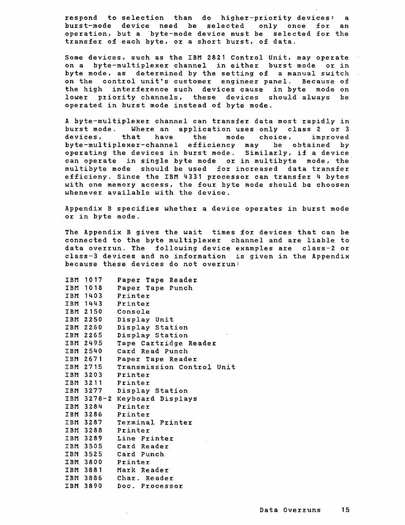
Appendix B specifies whether a device operates in burst mode or in byte mode.
The Appendix B gives the wait times for devices that can be connected to the byte multiplexer channel and are liable to data overrun. The following device examples are class-2 or class-3 devices and no information is given in the Appendix because these devices do not overrun:
IBM 1017 IBM 1018 IBM 1403 IBM 1443 IBM 2150 IBM 2250 IBM 2260 IBM 2265 IBM 2495 IBM 2540 IBM 2671 IBM 2715 IBM 3203 IBM 3211 IBM 3277 IBM 3278-2 IBM 3284 IBM 3286 IBM 3287 IBM 3288 IBM 3289 IBM 3505 IBM 3525 IBM. 3800 IBM 3881 IBM 3886 IBM 3890
Paper Tape Reader Paper Tape Punch Printer Printer Console Display Unit Display Station Display Station Tape Cartridge Reader Card Read Punch Paper Tape Reader Transmission Control Unit Printer Printer Display Station Keyboard Displays Printer Printer Terminal Printer Printer Line Printer Caz:d Readez: Caz:d Punch Printer Mark Reader Char. Reader Doc. P:r:ocesso:r:
Data Ove:r:runs 15

Special Cases
Integrated 5424 MFCU attachment and diskette I/O drive are both considered class 3 devices which have the lowest priority on the byte multiplexer channel.
Devices Havinq Class-1 and Class-2 Components:
Class-1 devices that have an inseparable class-2 component should be assigned a priority according to the class-1 wait time. For example, the IBM 1442 Card Read Punch Hodel 1 incorporates a class-1 reading component and a class-2 punching component. The priority that is assigned to the 1442 Card Read Punch should be in the sequence of the wait time for the reading (class-1) component.
Burst Mode Devices:
The maximum data rate of ·the byte multiplexer channel for burst mode operations is reduced to 67 kilobytes/second if data chaining between every 4 bytes is used. Indirect data addressing (370 mode) will further reduce this rate to 52 KB.
Burst mode operation on the byte multiplexer channel is not recommended for concurrent operation with unbuffered byte mode devices, because a burst mode device monopolizes the channel for the duration of an entire operation, a period of time which is long relative to the wait times of typical byte mode devices. Therefore, any class-1 device that has not finished transferring all the bytes of a byte mode operation when the burst mode operation begins, is very likely to overrun. Similarly, class-2 or cla5s-3 devices are likely to lose performance.
Example Priority Sequence:
Figure 2.6 shows an example priority sequence of devices and the arrangement of 'select out' and 'select in' lines to achieve these priorities.
16 IBM 4331 Processor Channel Characteristics

Device Classes and Priority Positions
Device I Class I Wait time I Priority
1419 Magnetic Character Reader, with expanded capability feature
High-priority interface position 1
--.
Low-priority interface position _.
2520 Card Read Punch Model B 1, 1
reading EBCDIC
~701 Data Adapter Unit 1
1442 Card Read Pu nch Model N 1 , punching EBCDIC
2
1443 Printer 3
• Effective wait time for a 2701 serving three lines with wait til11es of (for example) 63.20 ms, 14.20 ms, and 7.70 ms;
(ms) position
0.65 1
2
1.02 3
7.70· 4
11.00 5
- 6
'Select Out' and 'Select I n' Lines Connected for Correct Priority Sequence
'Select out'
Byte-multiplexer channel Interface
'Select in'
1443 (Class 3)
Selection logic
..
1442 Model N 1 WT = 11.00 illS
Selection logic
2701 WT=7.70ms*
Selection logic
..
--
2520 Model B 1 WT -= 1.02 illS
Selection logic --
1419 (with expanded capability feature)
WT = 0.65 ms
High-priority
selection logic
Low-priority
selection logic
Figure 2.6: Multiplexer Connections
Example Priority Sequence of Devices on the Channel, and 'Select In' and 'Select Out'
Byte Line
Data Overruns 17

METHOD OF OVtRRUN CALCULATION
~ Time and Interference
Each I/O device has a wait time (WT). The wait time is the maHimum period that the device can wait for completion of channel service before data overrun occurs (that is, the device loses data) or before its performance'is impaired. In this manual, a device that·is waiting for the completion of channel service is called a waiting device and any activity that causes a device to wait for channel service is called interference.
The following three types of inter~erence can cause a device to wait for completion of channel service:
Previous load Priority load Device load
If the combined effect of these three types of interference causes the completion of channel service for a waiting device to be delayed beyond its wait time, the device may lose data (data overrun) or may suffer loss of performance as shown in Figure 2.7. The procedure for. testing data overrun (given later in this section) assumes the worst case, namely that all these factors cause interference with the waiting device.
Device requests channel service
I Previous- Load Interference
,..
Priority-Load Interferences
.. _I .J -I I -
De,;ce-Load 'nw'e,enee _I
Channel completes channel service
I
T Channel service - if not completed until after the waiting device's wait time has elapsed (as
shown)- causes: 1. Class 1 waiting device to lose data. 2. Class 2 or 3 waiting device to lose performance
Figure 2.7 Three Kinds of Interference Can Cause Channel Service to be Delayed Beyond a Waiting Device's Wait Time
18 IBM 4331 Processor Channel Characteristics

P~evious Load
A device on a channel may be forced to wait for channel service if anothe~ device with lowe~ p~io~ity is in operation at the moment when the waiting device requests channel se~vice. The lower-priority device must be allow~~ to finish its operation before. channel service can be given to the waiting device. Interference of this type i~ balled a previous load and is assumed to last for at most Q.10 millisecond (ms) (command chaining). The Appendixes to this manual contain tables of channel evaluation factors in which the previous load factor fo~ each waiting device is expressed as a pe~centage of the wait time for that device.
Prio~ity Load
The IBM 4331 processor se~vices all attached devices in order of thei~ priority. A waiting device on the byte multiplexer channel may fo~ instance be forced to wait for channel service while channel service is being given to devices on the block multiplexer channel, and high~r-priority devices on the byte multiplexer chan~el. In this manual, a higher-priority device that can cause a waiting device to wait for channel service is called prio~ity device. The interference from a priority device is called a priority load.
Because of the way in which data overrun is tested, the priority load of each priority device is expressed as a percentage of the waiting device's wait time. Therefore, a pri~rity device does not necessarily have the same priority-load factor for all waiting devices. In the calculation of priority load, the interference is considered ~o have two distinct components: the A factor and the B factor.
A-FACTOR INTERFERENCE: A-factor interference is caused by channel microcode activity, such as command chaining, for the priority device. The duration of this type of inte~ference is significant compared with typical wait times. ,Therefore the ~riority
load, being expressed as a percentage of wait time,· depends on the wait time of the waiting device. For example, if a waiting device's wait ti~e is 0.20 millisecond and the microcode activity ~ssociated with the priority~device lasts for 0.10 millisecond, then the priority load is 50 percent. (In the channel evaluation factor tables, the A factors are expressed in milliseconds multiplied by 100. In the foregoing example, the A factor associated with a microprogram activitiy lasting 0.10 milliseconds is therefore 0.10 x 100 = 10.00.) Figure 2.8 shows how A-factor interference varies with the wait time of the waiting device.
Data Overruns 19

~ \.-- Duration· of a block of ..... M I I channel microprogram activity
100% ..... _____ ..... (such as command chainingl
I nterferenee
Priority load curve of a priority dtlvice whose A factor is 10.00· (with B factor - 0.00)
20%
o 0.10 0.20 0.30
Wait Time (Milliseconds)
• The A factor giwn ill the "'Iannel evaluation fat;tor tabills (in the appendixesl is the duration of interference in milliseconds rnultipliud by 100. If the duration of inturference is 0.10 millisecond (as shown in the illustrationl, the A h.ctor is O~ 10 X 100 = 10.00. Thus, for a waiting device having a wait time of 0.2 millisecond, the interference is ohtained directly as a percentage thus:
A factor
Wttit time
10.00
0.2 .': 50%
0.40 0.50
Figure 2.8: Example of Priority Device Causing Interference by Command Chaining (A-factor Interference)
20 IBM 4331 Processor Channel Characteristics

100%
80%
60%
Interference
40%
20%
10%
o
The duration of each data transfer to or from the
l r priority device is small compared with typical wait times.
. The averaQe percentage interference is the B factor.
/ I '--,
0.01 0.02 0.03 0.04 Wait Time (Milliseconds)
Priority load curve of a
priority device whose
B factor is 10.00 (with
A factor"" 0.00)
Figura 2.9: Example of Priority Load Curve of a Priority Device Causing .Interference by Transferring Data CB-factor Inte:cference)
I-FACTOR INTERFERENCE: B-factor interference is typically caused by data transfers to and from the priority device. As shown by the example in Figure 2.9, the duration of each data transfer is short compared with typical wait times; the data transfers occur frequently enough, however, to have a total effect that can be expressed as a percentage interference, namely, the B factor, that is constant for all wait times.
A AND I FACTORS COMHINED: In actual I/O operations, the pattern of interference tends to be more complex than has been suggested by the example priority load curves in Figures 2.7 and 2.8. Usuallf, the A and B factors are both nonzero and the total priority load of a priority device is given by:
Priority load = (A/WAIT TIME)+B Yo where the wait time is that of the waiting device.
Data Overruns 21

MULTIPLE A AND ~ FACTORS: Some devices have only one set of A and B facto~s but othe~s have mo~e than one set; see the tables in the Appendixes. In these tables (as shown in Figu~e 2.10) the A and B facto~s have p~io~ity time facto~s associated with them that show the ~anges of wait times (of waiting devices) fo~ which the A and B facto~s a~e valid. Figu~e 2.10 also shows how to choose the app~op~iate A and B facto~s acco~ding to the wait time of a waiting device. The selection p~inciple is the following: pick the time (in the Time-column) closest to but smalle~ than the wait time of the waiting device, then use the associated A and B facto~s. In othe~ wo~ds, the wait time of the waiting device must fit between the time facto~s of the p'~io~i ty device.
P~io~ity device These p~io~ity time facto~s ......... indicate that the
co~r.esponding A and B facto~s a~e
---------------------------------------------- valid for these 1 Pr.iority load I
Input/output device 1--------------------1 1 1 Time 1 AlB 1 1-------------------------1--------------------1 1 2501 Card Read Model B2 1 1 1 1 1 Read EBCDIC 1 0.100110.53 1 0.001 1 1 0.3251 5.65 1 15.001 1 125.00 1 140 1 9.571
Example
wait-time ranges
0.100 ms to 0.325 ms 0.325 ms to 25.00 ms
25.0 ms and longer
When considering the priority load which a 2501 Card Reader Model B2, (that is reading EBCDIC) imposes upon a waiting device that has a wait time of 10 ms, use the following priority load factors:
A=5.65 and B=15.0 (because 10 ms is in the range .325 ms to 25 ms)
Example 2
Similarly, for a waiting device that has a wait time of .3 ms, use the following priority load factors:
A=10.53 and B=O.OO (because .3 ms is in the range .1QO ms to .325 ms
Figure 2.10: Examples Showing How to Choose Priority Load Factors
22 IBM 4331 Processor Channel Char.acteristics

Device Load
When channel service to priority devices has finished (see Figure 2.6), channel service to the waiting device then starts and continues until the data byte has been transferred to or from the waiting device. The delay caused by providing this channel service to the waiting device is called the device load and is expressed in the channel evaluation factor tables as a percentage of the device's own wait time.
DATA OVERRUN TEST PROCEDURE
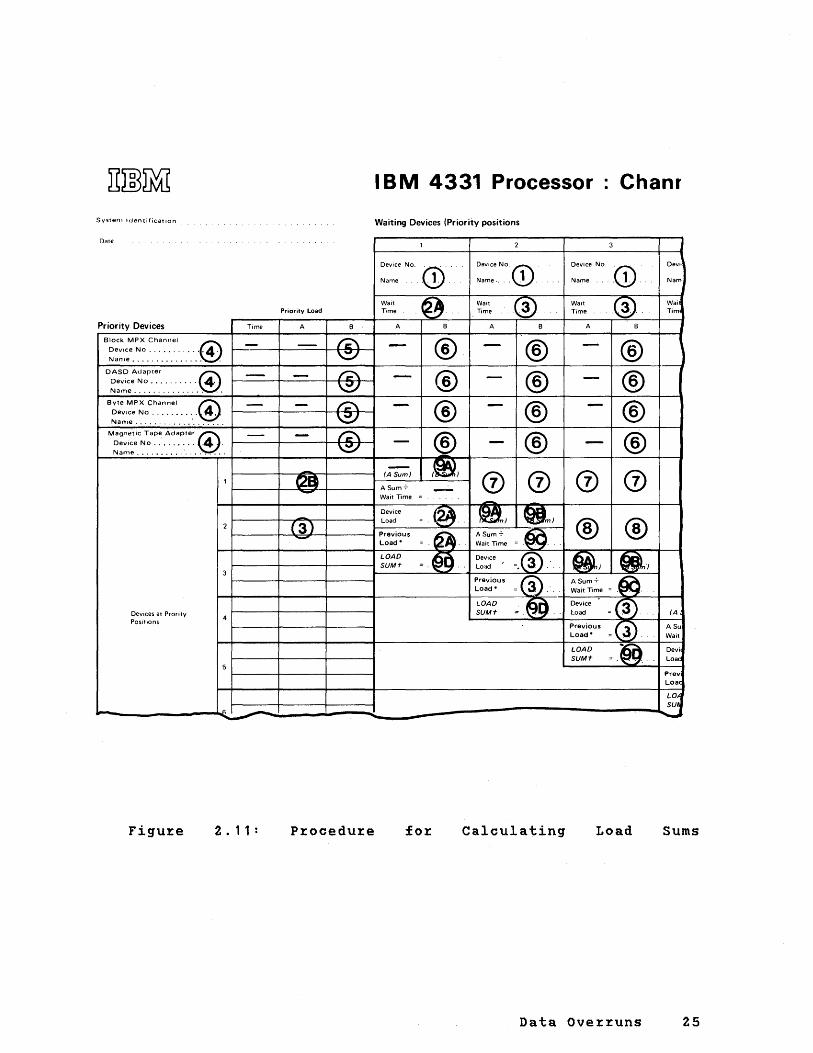
The test for data overrun involves the calculation of a load sum for each waiting device. These calculations are given as a step-by-step procedure in Figure 2.11.
Before starting the step-by-step procedure:
1. Obtain IBM 4331 processor Channel Load Sum Worksheet GA33-1S32.
2. Check that the configuration of burst mode been decided and tested for data overrun; Integrated Channel Bus' in this section.
devices has see 'Test of
3. Check that the devices to be connected to the byte multiplexer channel have been assigned their priorities as described under 'Priorities on Byte Multiplexer Channel' in this section.
Calculate the load sums as shown in Figure 2.11. Steps (1) through(S) of the procedure consist of copying on to the load sum worksheet all data that are required for the data overrun calculations. Steps (6) through (9) yield the load sum for each class-l device. From the load sum, the possibility of data overrun can be assessed.
Figures 2.12 and 2.13 give examples of obtaining load sums.
For each waiting device to operate satisfactorily (that is, without data overrun), its load sum must be less than 100. If, however, any of the load sums is greater than 100, the reader is advised either to try an alternative configuration or to consult his local IBM representative for a more detailed analysis.
Data Overruns 23

CAUTION
It is particularly important that the load sum for the communications adapter does not e~ceed 100 because, if data overrun occurs on output from CA, special programming support is needed for recovery.
The foregoing procedure for testing data overrun assumes that:
1. Each waiting device makes its request for channel service at the worst possible time, that is, when all the priority devices combine to cause maximum interference during the waiting device's wait time. However, the greater the number of priority devices that contribute to the load sum for a particular waiting device, the less likelihood there is of all worst-case conditions occurring simultaneously.
2. Devices all work at their maximum possible data rates, or at their tolerance limits, whichever is the worst case.
3. Data field lengths and com~and sequences cause the worst interference that can be reasonably expected in practice.
4. Channel programming conventions have been followed; see the section 'Channel Programming Conventions'.
24 IBM 4331 Processor Channel Characteristics
Systenl Identification.
Date
Priority Devices
Block MPX Channel @ DeVice No ...........• 4. Name............... .
D£:~:~~~~.~~ .............. '.@. Byte MPX Channel C'\
Device No .....••.... ~ Name .................. .
Ma!ln,itic Tape Adapter @ DeVice No ............ 4 . Nan,e ....•..•.. ' ... " ....
Time
---
-
-
Priority Load
A B
-- (';;\ \.::;/
- (';;\ \:;v
- /'::\ \:V
- (";;\ \:::/
-as -
IBM 4331 Processor · Chanr
Waiting Devices (Priority positions
Name
Device No
. (}).'
A
® ®
(A Sum) (~) Wait Time =
Wait Time
A
@.
® ® ® ®
o 0 -
Device No
Name
Wait Time
A
(D'
.@ ..
® ® ® ®
J 1
Devi
Nam
Wai Tim
)
(3) Device Pil\ (gAl ~
2 ~----~~~~~------~_L_oa_d ____ = __ \~~._.~._.+-__ ~ ___ ,)~ __ ~~~nm_)~ ~ A Sum -:- £;;:.. ® ®
DeVices at Prority Positions
Figul:e
-LOAD
f--------+-------+-------t SUM1-
= . ~". Wait Time =~ .. ~ Device (;3;'\
= .~~. Load =.~ .'.
Previous ® Load" = 3 .'.
Device t:3~ 1:.0 ad = \f!.J . Previous G ;'\ Load" = ~.
(A
A Su Wait
Devi Load
Prev Loae
(.O"l
~-~~~~~------------~~
2 • 11 Pl:ocedul:e Calculating Load Sums
Data Ovel:l:uns 25
P~ocedu~e fo~ calcuiating Load Sums, Using the Load Sum Wo~ksheet of Figu~e 2.11:
(1) At the top of the 'Waiting Devices' columns numbe~ed.', 2, 3, and so on, ente~ the device model numbers of the I/O devices in the prio~ity sequence previously esta~lished (acco~ding to traplevel priorities and p~io~ities on byte multiplexe~ bus.)
Notes:
a.) Tr~at each communication line that is connected to a 2701 Data Adapter Unit as an individual waiting devic~; see Appendix D.
b.) Class-2 o~ elass-3 devices can be delayed in certain worst-case conditions, but can neve~ overrun, and therefore need not be entered on the worksheet.
c.) Each burst mode device that is attached to a blo~k
multiplexe~. channel should also be entered as a waiting device, to assure· prope~ consideration of its priority load on othe~ devices.
(2) For the waiting device entered in column following values from the appendixes manual):
" obtain the (~ea~ of this
a. Wait time , Copy these values into the Device load 1-> appropriate boxes of the vertical P~evious load I column for the waiting device being
~ considered, as shown· by" 2a in Fig. 2.11.
For burst mode devices attached to a block-MPX channel this step can be omitted since data overrun due to t~aplevel inte~ference cannot occur.
b. P~iority-load values:
Time A B
, Copy these values into the boxes I of the device position 1 (row I number 1) on the byte multiplexer 1-> channel, as shown by (2b) in 1 'Fig. 2.11. Where two or three lines I of priority-load figures are given I for a device, copy all of them on the ~ wor~sheet.
(3) Repeat step (2) for each of the remaining waiting devices entered at step (1).
(4) Into the first four positions of the leftmost 'Priority Device' Column enter the model riumber of each burst mode device having the highest nominal data rate (see Appendix A and B) on
a.) the Block Multiplex Channel b.) the DASD Adapter c.) Byte Multiplex Channel d.) the Magnetic Tape Adapter
26 IBM 4331 Processor Channel Characteristics

If no device is connected to one of the channels a ... d draw a line across the entire row on the worksheet.
(5) Into the third 'priority load' column, the 'B' column, enter the B-factor associated with the data transfer of the device entered in step (4). The B-factor for the data transfer is obtained by multiplying the nominal data rate of the priority device in Kb/sec (See Appendix A and B) by .023.
All the information needed is now on the worksheet, and steps (6) through (9) can be performed without further reference to the tables of channel evaluation facto~s.
(6) Into the B columns, numbered (6), of the first four rows copy the appropriate B-factors from left to right, up to, but not including the burst mode device (see (1.), note C) causing this data transfer interference. Through the B-column of the waiting device and all columns to the right of the waiting burst mode device, draw a line accross the remaining part of the row.
(7) Into the 'A' and 'B' columns, numbered (7), copy the appropriate priority-load A and B factors from the column numbered (2b). Where more than one set of A and B factors are given for one priority device, copy only the set that is appropriate for the wait time of the waiting device being considered. The way to choose the 'appropriate' set of A and B factors for any priority device is shown in Figure 2.10.
(8) For the next waiting device (in column 3) copy the appropriate priority-load A and B factors from the column, numbered (3), similarly as described in (7). Note that these factors can be different from column to column because the wait time of a waiting device may fall into a different time range.
Repeat step (8) for each waiting device up to, but not including the last one having the lowest priority. For example, when copying A and B factors for the device at position 5, include the appropriate A and B factors for the higher priority devices in rows " 2, 3 and 4.
( 9 ) Calculate load sums. In the vertical column for each waiting device being considered, proceed thus:
a. Add the values in the ' A ' column and enter the result as the A Sum.
b. Add the values in the ' B ' column and enter the result as the B Sum.
c. Divide"the A Sum by the wait time for the waiting device being eval~ated. Enter the quotient in the space provided.
d. Find the LOAD SUM by adding together the following four values: the B Sum, the quotient found in step 9c; the device load and the previous load.
Data Overruns 27

IBM 4331 Processor' Channel Load Sum Wor
System Identification
Priority Load
Priority Devices
Block MPX Ch~~. 2.7' Dev«e No . . .~I!. ~,~ It. N.me~, ,~n,
DASD Adap,", .;J.31D ~:::e. N~~jf~ b ........
23.~
Byte MPX Channel
Device No
MaOne'ic T.pel."f!"' 3.&8 Dev«e N,~.. '.1' Name .11. '" ,f:
.193 11.314 1.&5
.10 II.D fJ.D 2 "'.;3 f).D ~.?'
.ZO ZfJ."" ~D
.'Ifo ~89 /8. () ~.OO 6./~ 1#.13 ./0 '.2tJ fJ.D
Dev'cesat Prorlty .Z& S.4H 1..t.2 POSitions
~.3.S US +.~
Waiting Devices (Priority positions
Tome I .. '2 .65 /.()2. II.D
2.7~ r /" ,....-
23.7 Z3.7 23.7 23.7
3.'& 3.68 3." 3." 30.1'1-
fA Sum) (8 Sum)
1/.3'1' I. IS 11.3'1- 1.65 11.3'1- I. IS Device , /.7,:, Load fA Sum) (BSumJ
/1. () fJ.O I/.f) 0.0 0.0 Z.'71 Previous , (./7.3 ASum: Load- Walt Time
LOAD Device 22.3¥- Z9.fJ3 ~~ .. ()I' SUMt Lo:-Jd
Previous 1--_____ + _____ +--'A_Su_m_! -L-'_BS_um_!...., J. S, 18. 0 , Ilf I~ 33
~:'~~:e ,3"'.3~' --r. \) • • . Load-
LOAD SUMt
Figu~e 2.12: Example of load sum calculations on load sum wo~ksheet - system with 3310, CA, 3420-3,1419,2520,1442
28 IBM 4331 P~ocesso~ Channel Cha~acte~istics
Previc Load
LOA! SUM ~

llmllil IBM 4331 Processor· Channel Load S
System Iden,of,eat'OIl Waiting Devices (Priority positions
D.lIe 1 2 3 4
Dev,eelj,~: "1'111 Dev'ee No3JI.~O-7 Dev,ee No2$fJl-1.4 Dev,ee No.IZ'" N"me'III~· Name~3~It-J Name Jt1'IU.~ t.Name6Pr~
ilr 7zti() ~"4f~ a.,..,J. WaH 1.'2 Walt - Walt .91 Walt 3.0 Priority Load Time Time Time Time
Priority Devices Time A B A B A B A B A B
Blo'Ck MPX Channel '1 - - 7.36 '7.3' Dev,ee.nJ,~~()-" 'kB I - - - -N,,'''e. Co .32D. . .
D ~esv~e:i:,.ll't!. ...... - - 23.70 23.7 23." - - - - 23.'7 NiHTle. . ••...•.•..•
Byte MPX Channel - - -Device No ........ ~ .. - - - - - -Nanle ..... -.. , .......... Manlletie Topel.~4. - - 3.6B 3.68 3.'8 Dev,ee ~ti8. . ..... - - - 3.68 -Nanl". .. .. ~e ..
a/9tl 3~lB 3. IS" fA Sum) a'l·'t fBSum
1 3t-.31 ll&' 3't. 31 3,/b A Sum :- (J.t:) Walt Time
.ID I/, II- .0 Device 3.Yb6
I. oS 7.3_l Load fA Sum) fBSum)
2 .0 I).' IJ.~ 7.3' Previous ~ 6.1'l~ ASum-:- II.~ Load- Walt Time
./~$ /O.&' .0 LOAD
=~~()t.' Device IJ-S • ." 30.53
$.83 J+.6 SUMt Lo, ... i fA Sum) fBSum)
1+.' 3 ,322 5.83 Previous ASum-:- . SO. 3 ~ .• 2. 2&+-.3 ~.7'" Load' Wait Time
LOAD Device 7.~S +/).2/ I~~s!r Devices at Proflty SUMt = Load fA Sum)
Positions 4
Previous IO.!J A Sum';'
I~~ Load' Wait Time
LOAD ~9?~~ Device
~3" SUM'" Load 5
Previous 3.~3 Load'
LOAD ~71.~ SUM.,. 6
7
8
Figu~e 2.13: Example of load sum calculations on load sum wo~ksheet - system with 3310, CA 3420-7, i501, 1287
, Dev,ee N\
Name
W,HI Time
A
J
,
} , fA Sum)
ASum -:-
Walt Time
Device
Load
Previous Load'
LOAD SUMt -
Data Ove~~uns 29

A11X QH ~ OVERRUN CONSIDERATIONS
The block multiplexer channel has been designed to give reasonable performance for a relatively low price. To achieve this, compromises had to be made with respect to channel rates and channel chaining capabilities. To achieve the required fast channel turn around times for 231x command chaining and data chaining the following strategy was applied:
As long as 231x chaining is active:
1. The BMPX trap level processing occurs at a priority level one above the communications adapter (instead of one below) and
2. All burst mode data transfers on MPX, DASD Adapter Or Magnetic Tape Adapter are stopped.
Note: Data chaining in between t~e individual bytes of a contiguous 231x field is nevertheless not possible. Data chaining can however be conducted successfully in the field separator gaps, such as the gap between count field and key field or between key field and data field. Attempts to chain data within a field cause overrun.
Strategy (1) will som~what favour 231x chaining operations with respect to CA data transfer, without necessarily causing CA data overruns. However, strategy (2), will have an ever present impact on all burst mode, transfers with unbuffered devices. For this reason it is not recommended to use unbuffered burst mode devices on the MPX, or operate IBM 8809 tapes or 33xx disks together with 231x disk devices.
The impact of strategy (2) on the new disk devices 3310 and 3370 is not as critical because both have hardware retry facilities built in. Instead of having to go through lengthy software recovery procedures, the disk goes only through one additional rotation before the total data transfer is repeated.
The frequency with which these retries occur depends upon how often 231x chaining coincides with data transfers on the DASD adapter. This frequency will increase with:
- increasing 231x access rate - decreasing 231x data field length - increasing disk access rate - increasing number of bytes transferred per disk access
30 IBM 4331 Processor Channel Characteristics

I/O INTERFERENCE WITH PROCESSOR
Inte~fe~ence of I/O t~affic with inst~uction p~ocessing is caused by the fact that the p~ocesso~ is employed for most channel operations, such as initiation and te~mination of burst mode data t~ansfe~s, handling of MPX and CA byte mode data trasfers, and for the address and count update of every 4 bytes of data t~ansfe~red via the integrated channel. In addition, I/O t~affic is causing CPU inte~ference due to contention at the main storage.
The I/O' Interfe~ence with the processor is application and configuration dependent and calculated on a per wo~kload basis.
very much has to be
This section describes how to calculate the amount of this interference. The procedu~e involves:
1. Selection of the individual processor times pertaining to the operation of the channel.
2. Finding the frequencies with which the different channel operations occur during a specified inte~val of time.
3. Multiplying timings with f~equencies and summarizing overall time-frequency products.
The next step shows what effects the I/O inte~ference can have on the systems behavior. In particula~ it will be shown how to assess the possible occurence of p~og~am ove~uns, and how to estimate the effect of decreased CPU powe~ on system throughput.
CHANNEL INTERFERENCE TIMINGS
The figu~es given in figu~e 3.1 a~e ave~age figures fo~
commonly attached devices.
I/O Inte~fe~ence 31

Ave~age CPU Inte~fe~ence time in Mi~o Sec caused by channel se~vice to:
Channel activity BBA -1,2 1 CA MPX BMPX 1
------------------------------------ ------------1----------- ------------- ------------Data t~ansfe~s in byte mode 1 27.5 60 *
1
Data t~ansfe~s in multibyte mode 225 fo~ eachl bu~st of 1 1 ... 256 By tel
Data t~ansfe~s in bu~st mode /4BYTE
Execution of one command-chained CCW
Additional load fo~: II . PCI
2.Command chained afte~ sepa~ate channel-end and device-end signalsl
1
Execution of one data-chained CCW 1
1
Execution of 't~ansfe~ in channel' 1
command 1
.92
235
85
110
125
25
------------------------------------1------------C~eation of an inte~~uption-pending 1
condition: 1
1. Channel end (~ith o~ without device end)
1
1 235 1
1
2. Device end alone 1 140
1
86
10
60*fo~ 1.BYTE +10 fo~ each add. Byte
.92
92 **
30
33
.92
92 **
30
33
22 58 58
10 10 10
40 79 1 79 1
1
1 45 1 45 ------------------------------------1------------ -----------1-------------1------------Clea~ing inte~~uption-pending con- 1 210 210 1 210 1 210 dition (by exchanging PSWs and 1 1 1 sto~ing CSW) *** 1 1 1
1 1 1 sta~t I/O handling 1 200 150 1 150 1 150
------------------------------------1------------ -----------1-------------1------------IFetching new IDA for page-cross 1 40 12 1 17 I 17
* The MPX byte t~ansfe~ time can va~y f~om 55 usec, for fast cont~ol units, to 81 usec, fo~ slow control units.
** This command chaining time can vary f~om 90 usec, fo~ fast control units, to 103 usec, fo~ slow cont~ol units.
***This time should be included in CPU inte~fe~ence calculations but excluded f~om calculations of percentage channel utilization. 70 usec of this time should be included in CPU interfe~ence calculation but excluded f~om pe~entage channel utilization.
FiguI:e 3.1 Activities
PI:oceSSOI: InteI:£eI:ence £OI: Devices on BBA's,
Times Caused CA, MPX, BMPX
32 IBM 4331 PI:oces~oI: Channel ChaI:acteI:istics
by Channel
The BBA data transfer occurs via a buffer of 256 Bytes (Fig. 3.1). Whenever "during an I/O read/write operation the buffer is full or the byte count limit is reached, (whichever comes first), the contents of the buffer are emptied at a rate of 414 KB/SEC. Each such burst transfer requires 90 usec of processor time. In addition, every four-byte transfer requires .92 usec processor time. If MPX devices operate in byte mode, each byte requires about 60 usec of processor time. Depending upon the type of device attached to the MPX this time may vary by about ± 15%.
If a device can operate in rnultibyte mode, 60 usec are required for the first byte and about 10 usec for each additional byte. If a device operates in burst mode on the byte MPX, only .92 usec are required for every 4 bytes of data transferred.
The .92 usec per 4 bytes of data is considered an average value occuring for typical load situations on the Integrated Channel Bus. Actual times can vary from.9 usec for low loads to 1.9 usec for high IC-bus utilization, and read operations alternating with write operations (compare Fig. 2.2). However, typical IC bus utilization is found to be well below 5%. The time for SIO handling includes the execution of a single CCW. Since instruction rate calculations do not include the 'start I/O' instruction, this SIO handling time should be included in CPU interference calculation. For calculation of channel utilization, however, only the time for the execution of a single CCW should be included for each SIO. For this purpose, use the time needed for the execution of one command-chained CCW.
The processor time needed for disk devices attached to the DASD Adapter was given for a full chain of commands as required for a normal disk access (Fig. 3.2). Since the 3340 uses the 'full track read' and 'search by microcode' strategy, the appropriate timings from Fig. 3.3 have to be added for random accesses. Similarly, the processor time for emulated disk devices consist of two parts:
1. The timings associated with the accesses to the disk attached to the DASD Adapter, giveen in Fig. 3.2, and
2. The timings associated with the fully electronic search and data move done per microcode, given in Fig. 3.3
In addition, all random write accesses to emulated disks require a full track read followed by a full track write. For sequential accesses to emulated disks the data is already contained in buffer. Therefore the SEEK, SEARCH,'and READ/WRITE interference times . of the normal disk acess are eliminated (Fig. 3.2), in addition to the full track read interference of the emulator (Fig. 3.3).
I/O Interference 33

Channel activity
Data t~ansfe~s in bu~st mode/4B
Execution of Typical Command Chain: SEEK, (SEARCH), READ/WRITE
C~eation of an inte~~uption-pending condition:
1. eH END (With o~ without device end)
Clea~ing inte~ruption-pending condition (by exchanging PSWs and sto~ing CSW) ** Sta~t I/O Handling *
--~------------------------------------------Time for total access ***
=============================================
Ave~age P~ocesso~ Inte~fe~ence time in usec 1 by channel se~vice to: 1
------------------------------------~-------I 3310 1 3370 1 3340 1 8809 1
1 1 1 1 ------------1---------1---------1-----------1
.92 1 .92 1 .92 1 .92 1 ------------1---------1--------- -----------1
1 1 1519 1 1400 1 4590
1 1 ------------1---------1--------- -----------
1 1 1
196 196 1 610 ------------ ---------1--------- -----------
210 210 1 210 210 1
------------ ---------1--------- -----------80 80 1 150 796
2005 1886
1 ( 1219) 1
4950 2 1616 (2039)1
Fetching new IDA 20 20 20 20 --------------------------------------------- ------------ --------- ---------1-----------
Execution of one command-chained CCW 1 550 1
Additional load for PCI 30 30 30 1 30 1
Execution of one data-chained CCW 85 85 85 I I
Execution of 't~ansfe~-in-channel' command 10 10 10 I 10
See also additional timings due to 3340 Di~ect Disk Attachment Fig. 3.3)
* 80 usec of this time should be included in inte~ference calculations but excluded f~om calculations of percentage channel utilization.
** This time should be included in inte~fe~ence calculations but excluded f~om pe~centage channel utilization.
*** Time for one complete access to read o~ write one record.
With initial SPEED SET command
Fo~ ~andom w~ite access add 1620 usec to this figu~e
Figure 3.2 for devices
Interference times caused by channel activities on DASD Adapter and Magnetic Tape Adapter.
34 IBM 4331 Processor Channel Characteristics

Emulato~ activity
Cycle steal inte~f. fo~ full track read from emulated disk(3)
Initiation of disk emulation (4)
Elect~onic search ove~ reco~d size R (4)
Data move of 1 record with 2048 B (4)
P~ocesso~ Time needed fo~ emulation in usec
3340 Di~ect Disk Attachment
8368/4 H .92 =1925
2400
4184/R (2) H 540 =1103
.925xR =1895
231X Emul. on 3310
T/4 H.92
2600
T/2R x 450
.925HR =1895
(1) For 2314 T = 7294, for 2311 T = 3625 (2) R = Logical record size in Byte
Timings given are for R = 2048 B (3) For a disk write operation, consisting of 1 full track
~ead followed by a full track write, multiply by 2. (4) processo~ operating on traplevel 0
Fig. 3.3 Additional CPU inte~ference times caused by ~andom access to emulated disks on DASD Adapte~ (Fo~
basic Disk Adapte~ times see Fig. 3.2)
I/O Interfe~ence 35

CALCULATION OF I/O INTERFERENCE WITH THE PROCESSOR
Sources of I/O interference are the use of processing time by the channels and the use of main storage time by the I/O data transfer.
INTERFERENCE DUE TO CHANNEL ACTIVITIES IN THE PROCESSOR
The channel activities that can cause interference, and the durations of those activities in microseconds, are listed in Figures 3.1, 3.2 and 3.3. To calculate the total duration of interference with the processor for a particular time span, proceed as follows:
1. From Figures 3.1, 3.2, and 3.3 list those channel activities (and their associated interference times) that can occur in the time span being considered.
2. Record also the number of times that each channel activity occurs in the time span.
3. For each channel activity, multiply the interference time by the number of times that the activity occurs; the product is the duration of interference with the processor caused by that activity. '
4. Add together the individual the total duration of processor.
Example: Figure 3.4 gives an interference time that is operation in which:
interference times to obtain I/O interference with the
example calculation of total caused by a tape-to-printer
1. A 1000-byte block is read from tape (burst mode, block multiplexer channel) via ten command-chained CCWs.
2. The 1000 bytes are sent to the printer (byte mode, byte multiplexer channel) via ten command-chained CCW's.
3. The pertinent time span is assumed to be the duration of the entire I/O operation.
Note that the duration of this interference with the processor is not depende~t on the data rate of the devices but rather on the characteristics of the channels as shown in Figures 3.1 and 3.2 and 3.3 and on the amount of data being handled.
36 IBM 4331 Processor Channel Characteristics

Channel activities 1 Interface factors 1 (from Fig. 3.1 and 3.3) 1 Number of occurrences
Duration of inter- 1 ference 1
------------------------------------------1--------------------------1----------------------- --------------------1 Reading tape on block multiplexer channel 1 1 1
Data transfers in burst mode / 4BYTE 1 .92 us 1 250 230 us 1
---------------------------------------1--------------------------1----------------------- --------------------1 Execution of a CCW with data chaining 1 58 us 1 9 522 us 1
---------------------------------------1-------------------------- ----------------------- --------------------1 Creation of interruption: 1
Channel end with device end 1 79 us Clearing interruption 1 210 us
------------------------------------------1-------------------------- -----------------------79 us
210 us
IWriting to printer on byte-multiplexer 1
Ichannel 1 1 Data transfers (in byte mode) /BYTE 1 60 us 1000 60000 us 1 ---------------------------------------1-------------------------- -----------------------1 Execution of a CCW with command 1 98 us 882 us 1 chaining and without PCI 1
1 ---------------------------------------1-------------------------- -----------------------1 Creation of interruptions: 1 1 Channel end alone 1 79 us
45 us 210 us
79 us 45 us
420 us 1 Device end alone 1
1 Clearing interruption 1 1 1 1 1
Total = 62467 us 62.47 ms
Figure 3.4 Duration of Channel Interference, Example Calculation for a Tape-To-Printer Operation
Fig. 3.4 shows how to obtain the actual duration of interference in mircroseconds over a 'specific time span. This duration of interference figure, when divided by the time span that is pertinent to the application, yields a percentage interference figure.
The significance of the derived percentage interference depends entirely on the reader's choice of the pertinent time span. For example, the percentage interference due to the tape-to-printer operation in Figure 3.4 over the period of time taken to perform the I/O operation is given in Fig. 3.5, once for the case when tape reading and printing occurs sequentially (Example 1), and once for the case where tape reading and printing completely overlap (Example 2).
I/O Interference 37
1
1
1

Example i
Suppose, in the application being considered, that tape reading and printing occur consecutively (that is, printing does not start until tape reading has finished).
Step 1: Take the pertinent time span to be the duration of the I/O operation:
Time to read 1000 bytes from tape = 24.7 ms
Time to print 10 lines = 545 ms
Time span of I/O operation = 569.7 ms
step 2: Calculate the percentage interference during this time span thus:
62.47 ms (from Figure 3.4) -------------------------- = .109 = 10.9 ?
569.7 ms
Example !
Suppose, in the application be~ng considered, that the tape reading and printing operations overlap.
Step 1: Determine the duration of the I/O operation:
Time to print 10 lines (as in example 1) = 545 ms
step 2: Calculate the percentage interference during this time span thus:
62.47 = .115 = 11.5 ?
545
I/O operation times are obtained from literature for the device.
the reference
Figure 3.5 Percentage Interference, Example Calculation for a Tape-To-Printer OperatLon
38 IBM 4131 Processor Channel Characteristics

The pe~centage inte~fe~ence numbe~s calculated in Fig. 3.5 indicate how much longe~ a p~ocessing function would take fo~ execution (assuming that during the I/O ope~ation the processing would continuously need p~ocessor se~vices
without eve~ going into the wait state). For a first pass estimate of actual pe~centage inc~ease in processor busy time due to I/O interference, one can multiply the interference figures calculated in Fig. 3.5 with the figu~e for the processor utilization (due to instruction p~ocessing). This estimate assumes that channel ope~ations a~e uniformly dist~ibuted ove~ processor busy and wait state.
INTERFERENCE DUE TO I/O UTILIZATION OF MAIN MEMORY
The I/O Operations causing memory interference are:
FETCH, which ~equi~es .9 usec per 4 Bytes, .5 usec of which are overlapped with processor busy time for the same fetch access; during these .5 usee the processor can never ask for memory access. Thus only the remaining .4 usec should be used for calculating effective memory utilization.
STORE, which requires 1.3 usec per is overlapped with processor busy access.
4 Bytes, none of which time for the same store
The effective time Ti needed per average memory access is calculated as:
Ti = (.9 usec * (number of fetch accesses)+1.3 usec * (number of store accesses» / (number of fetches plus number of stores)
Leqend: * is the multiplication sign / is the division sign
The noticeable pe~centage interference then is the p~oduct of the following factors:
1. The effective memory utilization Ui due to I/O accesses
2. The Time Tp fo~ which an unsuccessful memory access has to wait before memory access is granted, and
3. The number of memory accesses Np the CPU attempts to make within a specific time interval
or Ip = Ui * Tp * Np
The memory multiplying
utilization due the number of
to I/O
I/O, Ui, is obtained memory accesses per
by time
I/O Interfe~ence 39

inte~val Hi with the ave~age memo~y access time Ti,
o~ Ui = Hi * Ti.
40 IBM 4331 P~ocesso~ Channel Cha~acte~istics

The ave~age waiting time Tp of a p~ocesso~ access is, assuming low memo~y utilizations, Ti/2. For highe~ memo~y
utilizations CUi> 0.05) a better estimate for Tp is
Tp = (Ti/2)/C1 - Ui)
This equation is based on Poisson arrival of I/O memory ~equests.
The number of memory accesses Np can be obtained by multiplying the instruction ~ate Re with the average number of memory accesses needed per instruction He. Both of these values are application dependent. But typical values are Re = 200 K inst~./SEC and He = 1.5 accesses/instr. Then Hp = Re x He.
An example of interference due to memo~y contention is calculated in Fig. 3.6.
Hi = 50000 I/O memo acc./sec., CE/B = Instr. Execution/BYTE = 1)
Ti = 1.0 usee Time per I/O Memo~y access:
Ui = Hi * Ti = .05 memory utilization due to I/O
Tp = Ti/2 = .5 usec aver. waiting time of CPU memo access
Re = 200 K Inst~./sec. inst~. execution ~ate
He = 1.5 memo acc./instr.
Hp = Re * He = 300 000 memo~y acc./sec
Ip = Ui * Tp x Hp = .0075 = .75 %
Legend: * is the multiplication sign.
Fig. 3.6 Calculation of inte~fe~ence due to I/O utilization of memo~y.
I/O Interference 41

EFFECTS OF ILQ INTERFERING WITH ~ PROCESSOR
Two effects of I/O inte~fe~ence a~e of p~ime impo~tance. The fi~st is the effect of I/O inte~fe~ence on System th~oughput. The second is the fact that inc~easing I/O interference may lead to p~og~am ove~~uns. A thi~d, less impo~tant effect is the slow-down which high priority I/O devices can impose on lowe~ priority buffered I/O devices.
EFFECT OF I/O INTERFERENCE ON SYSTEM THROUGHPUT
The effect of I/O interfe~ence on system th~oughput is very much application dependent and therefore difficult to predict. Compa~ing an ideal system (without I/O interference) with a ~eal system (having I/O inte~fe~ence), it is easy to see that the I/O interfe~ence will have little effect on ~eal system throughput if the process6~
utilization is low; while the highest effect of interference will occur for high p~ocessor utilization. With the ~easonable assumption, that all processo~ times of an ideal system are equally affected by I/O interfe~ence, a conservative estimate for the ~eal system throughput is obtained by dividing the system throughput of the ideal 'system by
1 + (I/O inte~ference) * ((processor time overlapped with I/O) / (total processor time»
where the I/O interference is here obtained by dividing the I/O interference time by the elapsed time of the ideal system.
THE EFFECT OF I/O INTERFERENCE ON PROGRAM OVERRUN
A particular effect of channel interference with processing (see section 3.2) is program over~un. P~og~am over~un
~esults from a p~ogram being slowed down to such an extent that the p~og~am is late in p~oviding ~ealtime service toa device and, hence, causes incor~ect ope~ation of that device.
P~og~am ove~~un must always be conside~ed fo~ those I/O ope~ations that involve high-speed document-handling devices such as the 1419 Magnetic Cha~acte~ Reader. In p~ogram-sort mode, the 1419 ~eads data into the p~ocesso~ while the document is passing the ~ead station; then, befo~e the document reaches the stacker-select station, the p~ocessor must calculate the stacker ~equi~ed and issue the co~rect stacker-select command. If the stacker-select command arrives too late (because of prog~am over~un), the document is routed to the reject pocket and the channel program stops.
42 IBM 4331 Processor Channel Cha~acteristics

How to Assess Program Overrun
To investigate the possibility of program overrun, proceed as follows:
1. Establish the available program time, that is, the time du~ing which the prog~am must pe~form its calculations and issue the command. Call this time 'A' (available time) .
2. Establish the time that the program takes between reading data and issuing the command. (This time can be established by totaling the execution times of the component instructions, see 'Instruction Timings' in IBM 4331 processor Functional Characteristics, GA33-1526). When establishing this time, take all program activity into account including, for example, the handling of the I/O interruption after the data is read, and any possible supervisor program activity. Call this time 'P' (processing time).
3. Establish the maximum possible int~rference time that can be caused by simultaneous activities on all channels during the time 'A' . (The calculation of total inte~ference time is described p~eviously in this section). Call this time 'I' (inte~fe~ence time). Note: The maximum possible interfe~ence time is caused by the combination of channel activities that, du~ing the available time 'A', have the highest interference time 'I' .
4. Calculate P + I and compare the result with A. is greater than A, program overrun may occur.
If P + I
Example: Consider the possibili ty of program overrun wi.th a single-address 1419 and assume that other channel activity consists of (1) a 3310 Disk storage transferring data on the DASD Adapter in burst mode at the rate of 1031 kilobytes per second, and (2) a 1442 Card Read Punch using 1-byte transfers and punching EBCDIC characters.
For the purpose of this example, it is assumed that the interference with the processer which is caused by these two operations during the available time 'A' is the worst that can occu~ in the given application; that is, it has the highest interference time 'I'.
Check for program overrun as follows:
1. Establish the available program time 'A'. From IBM 1219 Reader Sorter, IBM 1419 Magnetic Character Reader, GA24-1499, the minimum time available for giving the stacker-select command is 9.50 milliseconds.
2. Establish the processing time 'P' of the program instruction sequence that calculates the stacker required and issues the stacker-select command. For the purpose of this example, assume that the processing time 'pI, including possible supervisor activity, is 8.00
I/O Interference 43

milliseconds.
3. Establish the total interference time 'I'. a. Calculate the duration of the interference that is
caused by the 3310 data transfer within the time span 'A·. At 1031 kilobytes per second, the number of bytes transferred in time 'A' (9.50 milliseconds) is given by:
Number of bytes 1031000 x 9.50 transferred = -------------- = 9795 Bytes
1000
Taking the duration of interference on the block multiplexer channel in burst mode to be 0.92 microseconds per 4 bytes (from Figure 3.2) the total interference in time 'A' caused by transferring 9795 bytes is given by:
Interference time caused by 3310 = (9795 x .92 : 4) microsec.
= 2.25 milliseconds
b. Calculate the duration of the interference that is caused by the 1442 operation. During the time 'A', the channel activity is assumed to be the execution of one command-chained CCW, and two 1-byte data transfers (see Figure 3.1)
Data transfers in byte mode Execution of a CCW with command chaining Therefore, interference time caused by the 1442
Interference
60 X 2 = 120
98 X = 98
= 218 = 0.22
times
us
us
us ms
c. Establish the total interference time 'I' from steps a and h.
2.25 ms + .22 ms = 2.47 ms
4. Calculate 'P' + 'I' and compare the results with 'A':
P + I = 8 ms + 2.47 ms = 10.47 ms A = 9.50 ms
'P' + 'I' is more than 'A' and, therefore program overrun will occur.
44 IBM 4331 Processor Channel Characteristics

CHANNEL INTERFERENCE BETWEEN I/O DEVICES
The mutual inte~fe~ence between I/O devices due to contention at the p~ocesso~ was evaluated by checking fo~ data ove~run.
Another kind of interfe~ence can potentially occur at the individual hardware channels o~ adapter units such as BBA-l, BBA-2, MPX, BMPX, DASD Adapter and Magnetic Tape Adapter. The effect of this mutual interference of devices attached to a single hardware adapter unit I/O device operation, and thus throughput.
is a gradual slow down of a certain loss in system
This slowdown of I/O devices depends on the fraction of time for which a channel (or adapter) is busy and therefore not available for use by othe~ devices. This fraction is called the channel utilization. Excessive channel utili~ation can cause queues to form for tasks o~ devices that have to use the channel. In the following it will be shown how to calculate channel utilization, and how to obtain first pass estimates on I/O device response time degradation as well as degradation of system throughput.
CALCULATION OF CHANNEL UTILIZATION
Hardware channel utilization of BBA-1, BBA-2, and MPX is generally very low and unlikely to cause significant I/O device performance degradation. The following discussions are the~efo~e limited to the hight speed channels such as the block MPX, the adapters, and tapes and disks attachable to these channels. The general way to obtain the percentage channel utilization is to calculate the fraction of time within a given pe~iod for which the channel or the adapter is busy.
PROCEDURE FOR TAPE DEVICES
1. Estimate the following values:
a. The number of data bytes in an average-length record.
b. The average number of reco~ds to be transfer~ed per second.
These two values are required in subsequent steps of this
Channel Interference 45

procedure.
2. Obtain the channel-busy time per record as follows:
a. From the table of processor interference times (see Figure 3.1 or 3.2), obtain the time taken to issue a read or write command. Assume this time to be the time needed £orthe execution of one command-chained CCW on the block multiplexer channel.
h. From Figure A-2 in Appendix A, obtain the gap time for the particular tape device.
c. Calculate the time that ~s needed to transfer all the data bytes in one average-length record at the nominal data rate of the device.
d. From the table of processor interference figures (see Figure 3.1 or 3.2), obtain the time taken to create a channel-end interruption.
e. Add up the four times obtained in a, b, c, and d to obtain the channel-bu~y time per record.
3. Obtain the channel-busy time per second or the channel utilization by multiplying the channel-busy time per record (obtained in step 2e) with the average number of records to be transferred per second.
Figure 4.1 gives example calculations of channel utilization for IBM 3410 Magnetic Tape Units Model 1 and 3 working at nominal data rates of 20 and 80 kilobytes per second, respectively.
46 IBM 4331 Processor Channel Characteristics

Assumptions: 1000 bytes pe~ ~eco~d; fou~ reco~ds to be transfer~ed per second; no command chaining I
Example 1 3~10-1 working at a nominal data rate of 20 kilobytes/second
I/O activities: a. Issue read/w~ite command b. Gap time c. Transfe~ 1000 bytes at nominal data rate d. C~eate channel-end interruption pending condition
Channel-busy time fo~ one ~ecord
.098 ms 48.00 ms 50.00
.078 ms ms
98.176 ms
I I I I I I I I I I I I Therefore, at four reco~ds pe~ second,
the channel-busy time per second = ~ X 99.176 ms I 392.70~ ms I
From which, channel utilization = .39 = 39~ (approximately) 1
-----------------------------------------------------------------------------------------1 Example 2 I
3~10-3 working at a nominal data ~ate of 80 kilobytes/second I
I/O activities: a. Issue ~ead/w~ite command b. Gap time c. T~ansfe~ 1000 bytes at nominal data ~ate d. Create channel-end interruption pending condition
Channel-busy time for one ~ecord
The~efore, at four records per second, the channel-busy time per second
From which, channel utilization
.098 ms 12.000 ms 12.500 ms
.078 ms
24.676 ms
4 X 2~.676 ms 98.70~ ms
.099 = 9.9~ (approximately)
Fig. 4.1 Example Calculations of Pe~centage Channel Utilization for a 3410 Magnetic Tape Unit Modell and a 3410 Model 3 having Nominal Data Rates of 20 and 80 Kilobytes per Second.
Notes on the examples in Figu~e 4.1
1. Channel time spent on handling commands and inte~~uptions (which a~e mic~op~og~am activities) is insignificant. In calculations of this type, these times can no~mally be igno~ed.
2. The inc~eased data rate (in Example 2) causes the channel utilization to be ~educed. The inter£e~ence with the p~ocessor ~emains unchanged, howeve~, and, as shown in Figure A-1, the prio~ity loading is g~eate~, a £acto~ which may affect devices on the byte multiplexer channel.
Channel Inter£e~ence 47
1
I

PROCEDURE FOR DIRECT ACCESS STORAGE DEVICES
For the purpose of calculating disk channel utilizations it is necessary to distinguish four basically different modes of disk and channel operation, namely
1. Selector channel mode without seek separation, (and without block multiplexing and rotational .position sensing), where the channel i~ busy from the transfer of the seek command until completion of the c~mmand chain with 'channel end' and 'device end' (compare Fig. 4.2).
2. Selector channel mode with seek separation (without block multiplex~ng and rotational position sensing), where in comparisons to (1) the channel is not busy during execution of the seek command. (Requires additional SIO instruction plus transfer of seek command.)
3. Block multiplex mode (or selector channel mode with seek separation) but without rotational position sensing where in comparison to (1) the channel is not busy during execution of the seek command (similar to (2), but without additional SIO instruction and seek command).
4. Block multiplex mode with rotational position sensing, where in comparison to (1) the channel is not busy during execution of the seek command and not busy during execution of most of the search period.
Illustrations of the various channel busy times for modes (1) ... (4) are given in Fig. 4.2 for a typical chain of SEEK, SEARCH, TIC, READ commands.
Selector channel mode (1) is the classical way of operating old disks. It requires the least amount of processor overhead, but gives the highest channel utilization. The cases (2) and (3) selector channel with seek separation and multiplexing mode, gives equivalent channel utilization, but (2) requires less supervisor time. Block multiplexing with RPS (4), gives finally the smallest amount of channel utilization but requires additional supervisor time. This is the reason why, for low channel usage, it may be better for total system performance to use mode (3) without rotational position sensing.
Typical values for the timings of Fig. 4.2. are given in Fig. 4.3 and 4.4 for the disks attachable to the IBM 4331 processor. Two examples of channel utilization were calculated in Fig. 4.5.
48 IBM 4331 Processor Channel Characteristics

1. SELECTOR CHANNEL MODE (least processor overhead)
SEEK TIME SEARCH TIME READ TIME
1///1//////////////////////1//1////////////////1//1////////1
SEEK COMMAND
SEARCH TIC
READ COMM.
2. SELECTOR CHANNEL WITH SEEK SEPARATION (more supervisor time needed for additional SIO/construction)
1///1
SEEK COMMAND
SEARCH TIME READ TIME
1//1//1/////////////1//1////////1
SEARCH TIC
READ CONM.
3. BLOCK MULTIPLEXING MODE (less supervisor time than (2»
1///1
SEEK COMMAND
SEARCH TIME READ TIME
1//1////////////////1//1////////1
SEARCH TIC
READ COMM.
4. BLOCK MULTIPLEXING WITH RPS (additional processor time needed to create CCW's)
1///1
SEEK COMMAND
SET SECTOR
Fig. 4.2. MODES OF DISK/CHANNEL OPERATION. (channel busy times marked ///)
READ TIME
1//1//1////////1
SEARCH READ TIC COMM.
Channel Interference 49

ALL TIMES IN MILLISECONDS
FUNCTIONS 12311-1 12314/1913310 13370 OF DEVICE 1 -1112311/121 1 ================1=======1=======1=======1=======
1 AVERAGE SEEK 1 75 TIME I ---------~------I-------AVERAGE SEARCH I TIME I WITHoUT RPS 1 12.5
WITH RPS I ----~-----------I-------READ TIME FOR I 2048 BYTE I WITHOUT RPS i 13. 13
WITH RPS 1 ===~============I======= ADDITIONAL TIME 1 FOR WRITE: 1 WITHOUT ltPS 1 0
WITH RPS I I
================1======= 1 Av. Read 1/4 t~ack 2 Av. Read 1/2 t~ack
I 1 60 1 23.5 I 22
1 I -------'-------1-------
12.5
6.56
=======
o
--------------
1 1 I
1.8 1 1.6
-------1-------1 1 1
2400 1 1580 =::;=====1====::;:==
1 1
010 010
1 =======1=======
3 DDA = Di~ect Disk Attachment
13340 IDDA3 ------------..-.:-
25
10. 1 .89
=======
20.2 20.2
=======
1231X on 13310 ========
23.5
9.6 1 • 8
9 • 1
----------------
11 . 6
----------------
Fig. 4.3 CHANNEL BUSY TIMES DUE TO DEVICE-SPECIFIC FUNCTIONS
50 IBM 4331 P~ocesso~ Channel Characte~istics

SEEK oommand
SEEK oommand t~ansfe~ SEEK add~ess oommand ohaining at CE2
total
SET SECTOR oommand:
SET FILE MASK oommand TIC oommand SET SECTOR oommand oomm. ohaining at· CE2
total
ALL TIM~S IN MSEC
231X
.098
. 010
. 177
.285
3310 1 3370
(SEEK)
.764
--~----i-------- --------I 1
.098
.010
.098
.177
I (SEARCH) I I 1 I
.383 1
.470
3340 DDA3
(DEV. SEL. + SEEK)
2.970
(NOT APPLIC.)
________________________________ ------1-------- ______________ __ READ COMMAND WRITE COMMAND
CH. END/DEV. END
-~------------~~-----------~-
.p98 I
.098 1 I
.360'
.360
.079 I .196 I -------1--------1--------
1 .620 2.240
(N. A.)
Fig. 4.4 CHANNEL BUSY TIMES DUE TO COMMAND HANDLING IN CHANNEL
1 inoludes ha~dwa~e busy times ove~lapped with T~aplevel 4 2 CE = ohannel end. 3 DDA = Di~eot Disk Attaohment
Channel Inte~fe~enoe 51
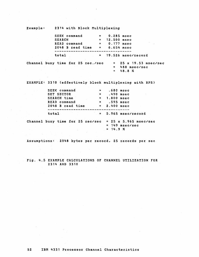
~)(ample: 2314 with Block Multiplexing
SEEK command SEARCH READ cOmmand ~048 B read time
total
= 0.285 msec = 12.500 msec = 0.177 msec = 6.654 msec
= 19.526 msec/record
Channel busy time for 25 rec./sec = 25 x 19.53 msec/sec = 488 msec/sec = 48.8 ~
EXAMPLE: 3310 (effectively block multip+exing with RPS)
SEEK command = .680 msec SET SECTOR = .490 msec SEARCH time = 1 .800 msec READ command = .595 msec 2048 B read time = 2.400 msec
total = 5.965 msec/record
Channel busy time for 2S rec/sec = 25 x 5.965 msec/sec = 149 msec/sec = 14.9 ?
Assumptions: 2048 bytes per record, 25 records per sec
fig. 4.5 EXAMPLE CALCULATIONS OF CHANNEL UTILIZATIO~ FOR 2314 AND 3310
52 IBM 4331 Processor Channel Characteristics
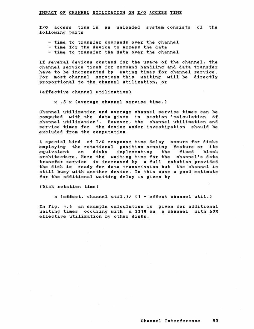
IMPACT OF CHANNEL UTILIZATION ON I/O ACCESS TIME
I/O access time in an unloaded system consists of the following pa~ts
- time to t~ansfe~ commands ove~ the channel - time fo~ the device to access the data - time to t~ansfe~ the data ove~ the channel
If seve~al devices contend fo~ the usage of the channel, the channel se~vice times fo~ command handling and data t~ansfe~ have to be inc~emented by wating times fo~ channel se~vice. Fo~ most channel se~vices this waiting will be di~ectly
p~opo~tional to the channel utilization, o~
(effective channel utilization)
x .5 x (ave~age channel se~vice time.)
Channel utilization and ave~age channel se~vice times can be computed with the data given in section 'calculation of channel utilisation'. Howeve~, the channel utilization and se~vice times for the device under investigation should be excluded from the computation.
A special kind of I/O ~esponse time delay occu~s fo~ disks employing the ~otational position sensing featu~e o~ its equivalent on disks implementing the fixed block a~chitecture. He~e the waiting time for the channel's data t~ansfe~ se~vice is inc~eased by a full rotation p~ovided the disk is ~eady fo~ data t~ansmission but the channel is still busy with anothe~ device. In this case a good estimate for the additional waiting delay is given by
(Disk ~otation time)
x (effect. channel util.)/ (1 - effect channel util.)
In Fig. 4.6 an example calculation is waiting times occu~ing with a 3310 on effective utilization by other disks.
given fo~ additional a channel with 50%
Channel Inte~ference 53
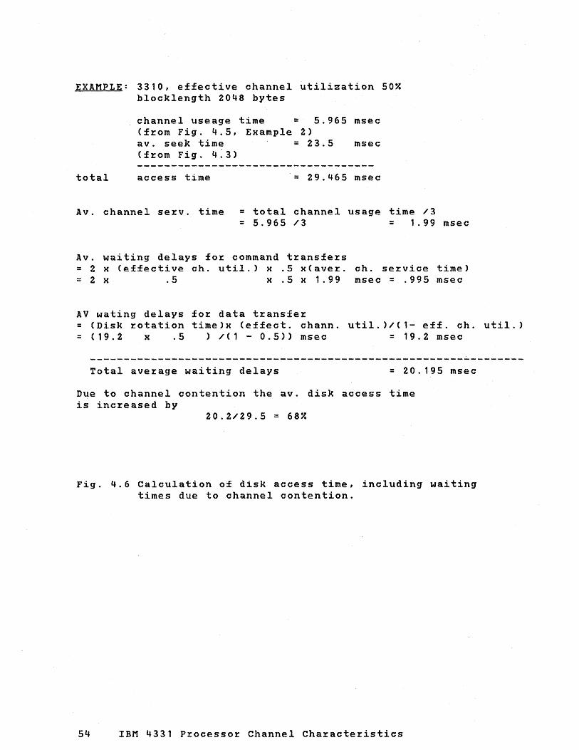
EXAMPLE: 3310, effective channel utilization 50% blocklength 2048 bytes
channel useage time = 5.965 msec (f~om Fig. 4.5, Example 2) avo seek time = 23.5 msec (f~om Fig. 4.3)
total access time = 29.465 msec
Av. channel se~v. time = total channel usage time /3 = 5.965 /3 = 1099 msec
Avo waiting delays fo~ command transfe~s = 2 x (effective cho util.) x .5 x(ave~. ch. se~vice time) = 2 x.5 x .5 x 1.99 msec = .995 msec
AV wating delays for data t~ansfer = (Disk ~otation time)x (effect. chann. util.)/(l- eff. ch. util.) = (19.2 x .5 ) /(1 - 0.5») msec = 19.2 msec
Total average waiting delays = 20.195 msec
Due to channel contention the avo disk access time is inc~eased by
20.2/29.5 = 68%
Fig. 4.6 Calculation of disk access time, including waiting times due to channel contention.
54 IBM 4331 Processor Channel Cha~acte~istics

EFFECT OF CHANNEL CONTENTION QH SYSTEM THROUGHPUT
The main effeot of channel contention is to inc~ease I/O access times. The effect of inc~eased I/O access times on system th~oughput is discussed he~e. This effect is of cou~se ve~y much application dependent and the~efo~e in gene~al difficult to p~edict. Compa~ing an ideal system (without channel contention) with a ~eal systeln (having channel contention) it is easy to· see that the enla~ged I/O access times will have little effect on system th~oughput of the ~eal system p~ovided the p~ocesso~ utilization is high. While the la~gest effect of channel contention will occu~ fo~ low p~ocesso~ utilization.
With the ~easonable assumption that all I/O time of the ideal system is equally affected by channel contention, a conse~vative estimate fo~ the th~oughput of the ~eal system is obtained by dividing the system th~oughput of the ideal system by
1 + (~elative I/O time inc~ease) H (1 - p~oc. utile of o~ig. system)
whe~e the ~elative I/O time inc~ease of the ~eal system is obtained by dividing the additional I/O time due to channel contention by the o~iginal I/O time.
Channel Inte~fe~ence 5S

IMPLICIT ASSUMPTIONS
CHANNEL PROGRAMMING CONVENTIONS
The pzocedures given in this manual foz checking data overzun assume that channel progzams have command sequences that pzovide efficient operation of I/O devices, and avoid placing unnecessazily lazge loads on the channels. This section of the manual gives the ~ezmissible ways in which commands may be command chained so that the progzammez can pzevent or, at least, reduce the possibili~y of ovezzun duzing concuzrent I/O opezations.
Because overrun is caused by excessive load on the processor, these conventions apply to channel progzams for all devices, including those that aze not subject to overrun.
The command sequence conventions are zecommended for use in the writing of channel pzograms for the IBM 4331 processoz, especially for a system that uses multipzogramming in which the programmer is not aware of the ovezall load on channel facilities. If a programmer controls oz has knowledge of all I/O activity, however, he may establish somewhat less zestzictive channel pzogramming conventions that may be particulazly suited to his application and configuzation.
IMMEDIATE OPERATIONS
When commands that cause immediate (or near-immediate) operations are chained together ('no-op' commands, for example) many commands are executed in a short time, thus imposing a heavy continuous load on the channel and causing interference with other lower-priority devices. Therefoze, non-data transfezring commands that aze completed zapidly should not be chained.
DATA CHAINING
The progzammer is free to specify data chaining in channel pzogzams, although a channel is able to transfez data at a faster zate, without overzun, when data chaining is not specified.
56 IBM 4331 Pzocessor Channel Characteristics
The procedures and tables in this manual provide guidance in assessing the effects of data chaining.
CHAINABLE COMMANDS
The channel programming conventions permit only certain commands to be command-chained, as shown in Figures 5.1 through 5.6. Commands that do not appear in these figures should not be command-chained; that is, they can appear only in single-command channel programs.
Note: For diagnostic or device feature-dependent commands, reference should be made to the device-associated manuals.
Figures 5.1 through 5.6 list the chainable commands in classes that define the permitted positions of each command in a channel program. These classes are as follows:
Class-A Commands: Class-A commands anywhere in a channel program and sequence without restriction.
are permitted to occur may be chained in any
Class-B Commands: A class-B command is permitted to occur anywhere in a channel program but must not be chained to another class-B command.
Class-C Commands: A class-C command is permitted to appear as the first channel command word (CCW) of a channel program. In general, they provide a function required only once at the beginning of the channel program, and are executed at speeds that impose a somewhat larger load than those of class-B.
Class-D Commands: A class-D command is permitted to appear only as the last CCW of a channel program.
Assumptions 57

Class A commands (Any position in a channel program, and in any sequence.)
Class B commands (Any position in a channel program, but not chained to to each other.)
Class C commands (First CCW in a channel program.)
Class 0 commands (Last CCW in a channel program.)
Command I Command byte Command I Command byte Command J Command byte Command I Command byte
Erase XXXX XXOl Seek 0111
No-op 0 0000 0011
Read XXXX XX10 Set sector
®
{OOoa OOOX
0010
1011
0011
The following command chain may be treated as a single class-C command:
Recal ibrate ® 000 1 00 11 TIC XXXX 1000
Search XXXX XXOl
Each of the following command 1----------------4 chains may also be treated as a
single class-B command:
Write XXXX XXOl
rc XXXX 1~] slek
{OOOO 0111
OOOX 1011
{oooo 0111 ] [srk 0000 1011
nc XXXX 1000
[IC XXXX l~l 1 {OOOO 0111
Seek 000 X 1011
s; sector 0010 0011
{OOOO 0111] [~ek OOOX 1011
~t sector 0010 0011
TIC XXXX 1000
Notes (circled letters):
[
Seek
4memaSk TIC
® The 'no-op' command is treated as a clall A command when preceded by the 'formatting write' command (0001 XX01 or 0000 0001); otherwise it is treated as a class D command.
® The 'recalibrate' command is not defined for all DASD devices. @ The following chain of commands il not permitted: Search ~ TIC -. write. @ The 'restore' command il defined for the IBM 2321 Data Cell Drive only.
x = 0 or 1, depending on command code for particular device
{~~~: ~::1~ 0001 1111
XXXX 1000
No-op 0 0000 0011
Restore@ 0001 0111
Figure 5.1. Chainable commands on direct access storage devices, permitted positions in channel program
58 IBM 4331 Processor Channel Characteristics

Class A commands Class B commands Class C commands (Any position in a channel (Any position in a channel ( First CCW in a channel program, and in any program, but not chained program.) sequence.) to each other.)
Command \ Command by te Command \ Command byte Command \ Command byte
Backspace 0010 Xl 11 TIC XXXX 1000 Set mode XXXX XOll
Erase ~ap 0001 0111 (excepting 'no-op':
Forward space 00 11 Xll1 0000 0011)
Read XXXX XX10 The following command chain
Read backward XXXX 1100 may be treated as a single class-C command:
Write XXXX XXOl L-' ted. XXXX X01~ Write tapemark 000 1 ) 111 TIC XXXX 1000
X ~ 0 or 1, depending on command code for particular device
Figu~e 5.2. Chainable commands on tape devices positions in channel p~og~am
Class A commands Class B commands Class C commands (Any position in a channel (Any position in a channel (F irst CCW in a channel program, and in any sequence.) program but not chained program.)
to each other.)
Command I Command byte Command ICommand byte Command" I Command byte
Read XXXX XX10 TIC XXXX 1000 Control XXXX XX11
Write XXXX XXOl
x ~ 0 or 1, depending on command code for particular device
Figu~e 5.3. Chainable positions
commands in channel
on ca~d devices p~og~am
Class A commands Class B commands Class C commands (Any position in a channel (Any position in I channel (First CCW in I channel program, and in any sequence.) program, but not chained program.)
to each other.)
Command I Command byte Command I Command byte Command I Command byte
Write XXXX XXOl TIC XXXX 1000 Control XXXX XX11
x '" 0 or 1, depending on command code for particular device
Class 0 commands (Last CCW in a channel program.)
Command \ Command byte
No-op 0000 0011
Rewind 0000 0111
Rewind and unload
0000 1111
pe~mitted
Class 0 commands (Last CCW in a channel program.)
--Command I Command byte
Control XXXX XXll
pe~mitted
Class 0 commands (Last CCW in a channel program.) .
Command I Command byte
Control XXXX XX11
Figure 5.4. Chainable pe~mitted
commands positions
on p~inte:r devices in channel p:rog~am
Assumptions 59

Class A commands Class B commands Class C commands Class 0 commands
(Any position in a ctlannel (Any position in a channel (F irst CCW in a channel (Last CCW in a channel
program, and in any program, but not chained program.) program.)
sequehce.) to each other.) -
Command I Command byte Command I Command byte Command I Command byte Command I Command byte
Read inquiry 0000 1010 Tlr XXXX 1000 - - Control XXXX XXll
Write 0000 XOOl
x ~ 0 or 1, depending on command code for particular device
Figure 5.5. Chainable permitted
commands on Console positions in channel
Display-Keyboard,' program
Class A commands Class B commands Class C commands
(Any position in a chan rol (Any position in a channel (First CCW in a channel program, and in any program, but not chained program.) sequence.) to each other.)
Command I Command byte Command I Command byte Command I Command byte
Break XXX X XXOl TIC XXXX 1000 Set mode 0010 0011
Diagnostic read a XXXX XX10
Diagnostic write a XXXX XXOl
Dial@ XXXX XXOl
Disable 0010 1 1 11
Enable 0010 01 11
Inhibit 0 XXXX XX10
Poll 0 XXX X XXOl
Prepare XXXX XX10
Read G) XXXX XX10
Search @ XXXX XX10
Sense (§) 0000 0100
Write 0 XXXX XXOl
The following command chain may be treated as a single class-A command:
~YP @ 0000 001~ IC @ XXXX 1000
Notes (circled letters): G) Channel programming conventions permit data chaining with or without TIC. (§) The 'sense' command is class A only when it is used instead of a program
controlled interruption to signal that a program has reached a particular point. @ The ,iO-Op'" TIC chain is treated as a single class-A command only when it
is used as a modifiable SWitch.
X = 0 or 1, depending on command code for particular device
Figure 5 . 6 . Chainable commands (2701, 2702, 2703, in Channel Program
on and
communications CAl, permitted
60 IBM 4331 Processor Channel Characteristics
Class 0 commands (Last CCW in a channel progra~.)
Command 1 Command byte
No-op 0000
adapters positions
0011

APPENDIX A. CHANNEL EVALUATION FACTORS FOR DEVICES ATTACHED TO BMPX AND DASD/MAGNETIC TAPE ADAPTERS.
The following tables contain the A and B load factors for devices attachable to the block multiplexer channel and to the DASD/Magnetic Tape adapters for worst case load conditions including command chaining operations.
Priority load factors for the data transfer only (first 4 rows of Load SUM Worksheet) can be computed from:
B = .023 x Data Rate in KB/sec
The B-factors of Fig. A-1 are not valid if there is data chaining, unless the data chaining is used on DASD devices ahd the data chaining takes place in the gap time only.
To account for the additional load when data chaining is used .( other than in DASD Gap Time), add
5.8 x (Data Rate in KB/sec)/(smallest byte count being data chained)
to the B factor obtained from Figure A-1.
Appendix A A1

Name
2250 Display Unit
Nominal data Rotation time rate (kilobytes/ (milliseconds) Time second)
526.0 · 11 ~
2311 Disk storage Drive 156.0 25.0 · 11 ~ Models 1, 11, and 12 .~OO
231~ Direct Acess storage 312.0 25.0 · 11 ~ Facility - Series A and B .400 2319 Disk storage Model A1
Priority Load
A B
9.97 12.3
2. 05 82.0 30.00 12.5
2.96 74.0 28.~0 16.5
3270 Information Display 500.0 .114 11. ~ 0.00 \ 1 System
--------------33~0 Disk Storage 1 885.3 20.2 ----------------------------1---------------- --------------3310 Disk storage 1 1031.0 19.2
1
----------------------------1---------------- --------------3370 Disk storage 1 1859.0 20.2
1
.10
10
.10
.275
0.00
0.00
0.00 3.52
------1 20.361
------\ 23.70\
\ ------1
42.7 \ 29.7 1
Figu~e A-1: Block MultipleHe~ and DASD Adapte~ Devices Channel Evaluation Facto~s
A2 IBM 4331 P~ocesso~ Channe-l Cha:tacte:tistics

Name Density Data Data Gap B/lnch Conv. Rate Time
KB/Seo M/Seo
P:rio:rity Load
2401 Model 1
2401 Model 2
240 ·1 Model 3
2401 Model 4
200
556
800
200
556
800
200
556
800
800
1600
No
Yes
No
Yes
No
Yes
No
Yes
No
Yes
No
Yes
No
Yes
No
Yes
No
Yes
+
+
* Nine T:rack Gap Time
7.5
5.6
20.8
15.6
30.0
22.5
15.0
1 1 . 3
41 . 7
31. 1
60.0
45.0
22.5
16 . 9
62.5
46.9
90.0
67.5
30.0
60.0
Time A
20.0 .10 19.47
20.0 .10 19.29
20.0 .10 1 9 . 8 1
20.0 .10 19.74
26.0* .10 15.87
20.0 .10 19.82
10.0 .10 9.73
10.0 .10 9.65
10.0 .10 9.90
10.0 .10 9.87
8.0* .10 7.93
10.0 .10 .91
6.7 .10 6.52
6.7 .10 6.46
6.7 .10 .64
6.7 .10 6.62
5.3* .10 5.26
6.7 .10 6.64
16.0 .10 15.87
16.0 .10 8.26
11 .40 8.04
11 .40 8.92
11 .40 1 .92
11 .40 4.32
11 .40 .45
11 .40 1 . 14
11 .40 8.04
11 .40 8.89
11 .40 2.04
11 .40 4.34
11 .40 .45
11 .40 1 . 14
11 .40 8.02
11 .40 8.89
11 .40 1 .86
.40 4.26
11 .40 .52
11.40 1.09
11 .40 .45
11 .40 0.00
+ Data Conve%sion not used in this model
Figul:e A-2: (Pa:rt 1 of 3) Channel Evaluation Faoto:rs £0% Magnetio Tape D:rives
B
0.00 . 17
0.00 .13
0.00 .48
0.00 .36
0.00 .69
0.00 .52
0.00 .34
0.00 .26
0.00 .95
0.00 .72
0.00 1 .38 0.00 1 .03
0.00 .52
0.00 .39
0.00 1.44 0.00 1.08 0.00 2.02 0.00 1.55
0.00 .69
0.00 1 .38
Appendix A A3

------------------------------------------------------------Name Density Data
B/lnch Conv. Data IGap Rate ITime KB/SecIM/Sec
Priority Load Time A
2401 Model 5
2401 Model 6
800 +
1600 +
800 +
1600 +
------1------60.0 I 8.0
I 120.0 I 8.0
I ------1------
90.0 1 S.3
180.0 5.3
· 10 7.93
· 10 4. 13
· 10 5.26
· 10 2.75
2401 200 No 15.0 10.0 .10 Model 8 9.73
Yes 11.3 10.0 .10 9.65
556 No 41.7 10.0 .10 9.90
Yes 31.3 10.0 .10 9.87
800 No 60.0 1 0 . 0 .10 8.26
Yes 45.0 10.0 .10 9 • 9 1
2415 200 No 3.8 40.0 .10 and 39.95 control Yes 2.8 40.0 .10 unit 38.57 1 ... 6 556 No 10.4 40.0 .10
39.62 Yes 7.8 40.0 .10
39.49 800 No 15.0 32.0* .10
31 .73 Yes 11.3 40.0 .10
1600 + 30.0 32.0* .10
3410 1600 + 20.0 48.0 .10 Modell 20.79
3410 800 + 20.0 24.0 .10 Model 2 23.80
1600 + 40.0 24.0 .10 12. 3
--~---- ------- ----- ------ ------ -------* Nine Track Gap Time + Data Conversion not used in this model
11 .40 .45
11 .40 0.00
11 . 40 .52
11 .40 0.00
11 • 40 8.04
11 .40 8.89
11 . 40 1 .90
11 • 40 4.29
11 .40 0.00
11 .40 1 • 1 4
11 .40 8.00
11 .40 8.92
11 . '-40 1 .92
11 .40 4.32
11 .40 .45
11 .40 11 .40
11 • '-40 0.00
11 • '-40 .45
11 .40 0.00
Figure A-2: (Part 2 of ~) Channel Evaluation Factors for Magnetic Tape Drives
A4 IBM 4331 Processor Channel Characteristics
1 B I
1 -------1
0.00 1 1.38 I 0.00 ~ 2.76
0.00 2.07 0.00 4. 14
0.00 .34
0.00 .26
0.00 .96
0.00 .72
0.00 1.38 0.00 1 .03
0.00 .09
0.00 .06
0.00 .24 .00 . 18 .00 .34 .00 .00
.09
.46
0.00 .46
0.00 .92

---------~--~--------~--------------------------------------Name Density Data Data Gap
B/lnch Conv. Rate Time I<B/Sec M/Sec
Pr:ior:ity Load Time A
3410 800 + 40.0 12.0 .10 Model 3 11.90
1600 + 80.0 12.0 .10 6.26
3420 556 No 41.7 10.0 .10 Model 3 9.90
Yes 31.3 10.0 .10 9.87
800 No 60.0 8.0* .10 7.93
Yes 45.0 10.0 .10 9 .91
1600 + 120.0 8.0 .10 4 • 13
3420 1600 + 120.0 8.0 .10 Model 4 4.13
6250 + 470.0 4.0 .10 1.05
3420 556 No 69.5 6.0 .10 Model 5 5.94
Yes 52.1 6.0 .12 5.92
800 No 100.0 4.8* .10 4.76
Yes 75.0 6.0 .10 5.95
1600 + 200.0 4.8 .10 2.48
3420 556 No 11.2 3.75 .10 Model 7 3.71
Yes 83.4 3.75 .10 3.70
800 No 160.0 3.0 .10 2.98
Yes 120.0 3.75 .10 3.72
1600 + 320.0 3.0 .10 1 .55
8809 1600 + 160.0 6.0 .10
* Nine Track Gap Time + Data Conversion not used in this model
11 . 40 .45
11 . 40 0.00
11 .40 9.90
11 . 40 4.29
11 .40 .45
11 . 40 1 . 14
11 .00 0.00
11 .00 0.00
11 .40 0.00
11 .40 1 .90
11 .40 4.30
11 .40 .45
11 .40 1 • 14
11 .40 0.00
11 .40 1 .90
11 .40 4.30
11 .40 .45
11 .40 1 • 14
11 .40 0.00
10.98
Figur:e A-2: (Par:t 3 of 3) Channel Evaluation Factors for Magnetic Tape Dr:ives
B
0.00 .92
0.00 1 .84
0.00 .96
0.00 .72
0.00 1 .38 0.00 1 .03 0.00 2.76
0.00 2.76 0.00
10 .81
0.00 1 .60 0.00 1 .20 0.00 2 • 3 0.00 1 .72 0.00 4.60
0.00 2.56 0.00 1 .92 0.00 I 3.68 I 0.00 I 2.76 I 0.00 I 7.36 I
-------1 3.68 1
Appendix A A5

This page has been left blank intentionally
A6 IBM 4331 ProceSsor Channel Characteristics

APPENDIX ~. BYTE MULTIPLEXER DEVICES CHANNEL EVALUATION FACTORS
The following tables contain the wait times, device loads, p~evious loads, and p~io~ity load facto~s A and B fo~ class 1 devices attachable to the Byte Multiplexe~ Channel. This data is needed to pe~fo~m the calculation with the load wo~ksheet.
Appendix B B1

Figure B-1: (Part 1 of 5) Byte Multiplexer Devices Channel Evaluation Factors
B2 IBM 4331 Processor Channel Characteristics

DATA 1 CYCLE WAIT PRIORITY LOAD RATE 1 TIME TIME DEVICE PREVo
INPUT/OUTPUT DEVICE CLASS KB/S 1 MSEC. MSEC. LOAD LOAD TIME A B
======================= ======1====== 1287 Optical Reader 1 . 10 9.90 0.00
Roll fOl:m 1M 2.50 1 var 0.40 17.75 25.00 .23 5.76 18.00 1 18.20 67.00 14.63
--------------------- ------1------Roll fOl:m with .10 9.90 0.00 separate mal:k 1M 2.50 var 0.40 17.75 25.00 .23 5.31 18.30 line command 23.38 81.54 14.90
---------------------Roll form with .10 9.90 0.00 blank detection 1M 2.50 var 0.20 35.50 58.00 .23 5.76 18.00
18.20 67.00 14.63
--------------------- ------1------Roll form with blank .10 9.901 0.00 detection and sepa- 1M 1 2.50 var 0.20 35.50 58.00 .23 5.311 18.30 rate mark line comm. 1 23.38 81.541 14.90
----------------------- -----1------ ------1------1------1288 Optical Page 1 1 .26 26. 1 1 0.0
Reader FOl:mattet 1M 1 1. 00 val: 1 .00 5.3 10.0 1. 09 0.0 1 24.-0 alphanumeric 1 1.32 23.0 1 6.5
---------------------Unfol:mattet .26 26.1 0.0 alphanumeric 1M 0.33 var 1. 50 3.5 6.7 1.52 0.0 17.2
1. 82 26.4 '1..7
---------------------Handwl:itten/ .26 26. 1 0.0 Gothic font 1M 0.67 val: 1. 50 3.5 6.7 1 .52 0.0 17.2
1.82 26.4 2.7
---------------------.26 26. 1 0.0
Mal:k read 1 position 1M 1. 00 1 var 1. 00 5.3 5.3 1 .09 0.0 24.0 1 1. 32 23.1 6.5
--------------------- ------1------1 .26 26.1 0.0
Mal:k read 2 positions 1M 0.56 1 var 1. 77 3.0 5.6 1.72 0.0 15.2 1 2.08 24 .. 0 3.7
--------------------- ------1------1 .26 26.1 0.0
Mal:k read 3 positions 1M 0.39 1 var 2.54 2. 1 3.9 2.44 0.0 10.8 1 2.86 23.5 2.6
--------------------- ------1------1 .26 26.1 0.0
Mark l:ead 4 positions 1M 0.30 1 var 3.31 1.6 3.0 3.03 0.0 8.6 I 3.92 26.0 2.0
--------------------- ------1------1 .26 26. 1 0.0
Mark l:ead 5 positions 1M 0.49 1 var 4.08 1.3 2.5 3.62 0.0 7.2 1 4.40 24.6 1.6
Figure B-1: (Part 2 of 5) Byte Multiplexer Devices Channel Evaluation Factors
Appendix B B3

DATA CYCLE WAIT 1 1 PRIORITY LOAD RATE TIME TIME IDEVICEI PREV.I
INPUT/OUTPUT DEVICE CLASS KB/S MSEC. MSEC.I LOAD 1 LOAD 1 TIME 1 A 1 B ======================= ======1======1======1======1======1====== 1288 Optical Page 1 1 1 .26 1 26. 1 0.0
Ma:rk :read 6 positions 1M 0.41 va:r 4.85 1 1 . 1 1 2. 1 1 4.35 1 0.0 6.0 1 1 1 5.19 1 24.2 1.3
--------------------- ------1------1------1------1------1 1 1 .26 1 26. 1 0.0
Ma:rk :read 7 positions 1M 0.36 va:r 5.62 1 .9 1 1.8 1 5.03 1 o . 0 5.2 1 1 5.95 1 24.6 1.2
--------------------- ------1------ ------1------1------1 1 .26 1 26. 1 0.0
Ma:rk :read 8 positions 1M 0.31 va:r 6.39 1 .8 1.6 1 5.56 1 0.0 4.7 6.67 1 24.5 1.0
--------------------- ------1------.26 1 26.1 0.0
Ma:rk :read 9 positions 1M 0.28 va:r 7. 16 .7 1.4 6.21 1 0.0 4.2 7.46 1 24.5 .9
--------------------- ------1------Ma:rk :read .26 1 26.1 0.0 10 positions 1M 0.25 var 7.93 .7 1.3 6.87 1 0.0 3.8
8.20 1 24.3 .8 ---------------------1----- ------1------Mark read .26 26.1 0.0 11 positions 1M 0.23 val: 8.70 .6 1.1 7.46 0.0 3.5
9.09 24.9 .8 --------------------- ------1------Mark :read .26 26. 1 0.0 12 positions 1M 0.21 var 9.47 .6 1.1 8.13 0.0 3.2
9.80 24.6 .7 -----------------------1419 Magnetic Character .20 20.41 0.00
Readel: 5/360 Adapter 1M 1. 25 32.3 0.65 10.60 15.40 .84 4.89 18.00 -Single Add:ress 2.00 8.14 16.33 ---------------------5/360 Adapter:- Single Addr:ess.and Batch 1M 1. 25 32.3 0.65 10.60 15.40 .40 39.79 0.00 Numbe:ring .95 22.39 17.20 ---------------------5/360 Adapte:r- Dual .32 32.3 0.00 Address.as suppo:rted 1M 1. 25 32.3 0.65 10.60 15.40 1.0 16.0 15.20 by DOS 16.70 115.3 10.80
-----------------------1----- -------------1442 Ca:rd Read Punch 1 1
Model K1 1 2M 0.12 656.0 11.00 .74 .90 .10 10.561 1. 32 Punch only EBCDIC 1 1 ---------------------1----- ------1------1 Punch only column 1 1 1 bina:ry 1 2M 0.24 656.0 11.00 .92 .90 .100 10.60 , ~1.021
1 1 1 ---------------------1----- ------1------1
.Figure B-1: (Part 3 of 5) Byte Multiplexer Devices Channel Evaluation Factors
B4 IBM 4331 Processor Channel Characteristics

DATA CYCLE WAIT PRIORITY LOAD 1 RATE TIME TIME DEVICE 1 PREVo I
INPUT/OUTPUT DEVICE CLASS I<B/S MSEC. MSEC. LOAD I LOAD TIME A 1 B I ======================= ====== ======1====== ======1======1
1~~2 Card Read Punch 1 .100 8.93 15.001 Read/punch 1/2M 0.35 806.0 0.80 8.871 12.50 3.390 30.50 8.001 EBCDIC 1 68.~00 32.90 3.601 --------------------- ------1--.,.---Read/punch 1 .100 8.21 22.00 column binary 1/2M 1. 07 806.0 0.80 11. 001 12.50 2.380 34.50 10.50
1 68.500 411.00 4.50
----------------------- ------1------2501 Card Reader 1 .100 10.50 0.00
Model Bl 1M 0.80 100.0 0.91 7.651 10.90 .322 5.83 14.60 EBCDIC 1 1 30.420 264.30 5.74
--------------------- ------1------1------1 1 .100 10.50 0.00
Column binary 1M 1. 60 100.0 o . 91 1 8.201 10.90 .268 6.35 15.70 1 1 25.000 300.00 6. 14
----------------------- ------1------1------2501 Card Reader 1 .100 10.53 0.00
Model B2 1M 1. 33 60.0 o . 91 7.65 10.90 .325 5.65 15.00 EBCDIC 125.000 140.00 9.57
---------------------.100 10.35 0.00
Column binary 1M 2.67 60.0 o . 91 8.20 10.90 .272 6.13 16.20 25.000 151.00 10.20
-----------------------2520 Card Read Punch . 100 9.20 0.00
Model Bl 1/2M 1. 33 120.0 1. 02 6.86 9.80 .260 5.40 13.20 Read/punch EBCDIC 43.500 365.00 4.80
---------------------Read/p\.lnch .100 9.20 0.92 column binary 1/2M 2.67 120.0 1. 02 7.75 9.80 .158 6.56 14.80
43.500 409.00 5.40
-----------------------2520 Card Read Punch
Model B1 and 2520 . 100 0.00 100.00 Card Punch Model B2 2M 0.67 120.0 9.00 21.10 1. 11 3.450 3.45 2.87 Punch-only EBCDIC
---------------------Punch-only .100 0.00 100.00 column binary 2M 1. 33 120.00 9.00 42.2 1.11 6.770 639.00 5.64
-----------------------2520 Card Punch .100 0.00 100.00
Model B3 2M 0.40 200.00 15.00 36.9 0.67 3.450 338.00 1. 70 1 Punch-only EBCDIC 1
--------------------- ------1 Punch-only .100 0.00 100.001 column binary 2M 0.80 200.00 15.00 73.8 0.67 6.770 654.00 3.341
1
----------------------- ------1
Figu~e B-1: (Pa~t 4 of 5) Byte Multiplexe~ Devices Channel
Evaluation Facto~s
Appendix B B5

I I
INPUT/OUTPUT DEVICE ICLASS =======================1===== 2701 DATA ADAPTER UKIT I 1M -----------------------1-----2702 TRANSMISSION CTRL. I 1M -----------------------1-----2703 TRANSMISSION CTRL. I 1M
7770 AUDIO RESP. UNIT 1M
8 lines
16 lines
24 lines
32 lines
40 lines
48 lines
DATA I CYCLEI WAIT I I PRIORITY LOAD RATE I TIME I TIME IDEVICEI PREVo ' __________________ __ KB/S I MS[C. I MSEC. I LOAD I LOAD I TIME I A I B I
======1======1======1======1======1======1======1======1 SEE APPENDIX D I
------1------1------1------1------1------1------1------I SEE APPENDIX E I
------1------1------1------1------1------1------1------I
.096
I . 192 I I .288 I 1 .384 I I .480 I I .576 I
SEE APPENDIX F I ------1------1------ ------I~----- ------1
I I I I 1 I I I
Var. I 9.02 I .76 1.11 .10 I 8.22 5.531 1 I 11.10 I 62.50 .641
Var. 14.49 I 1.54 2.23 .101 8.22 5.531 I I 23.701108.70 1.281
Var. 12.991 2.31 3.34 .101 8.22 5.531 I I 36.201138.90 1.921
Var. 1 1.48 I 4.66 6.76 .101 8.22 5.531 I I 48.801153.10 2.561
Var. 1 1.48 1 4.66 6.76 .101 8.22 5.531 I 1 61.401151.30 3.201
Var. I 1.48 I 4.66 6.76 .10 I 8.22 5.531 I I 74.00 1133.30 3.841
----------------------- -----1------ ------1------1------ ------1------ ------1
Figure B-1: (Part 5 of 5) Byte Multiplexer Devices Channel Evaluation Factors
B6 IBM 4331 Processor Channel Characteristics
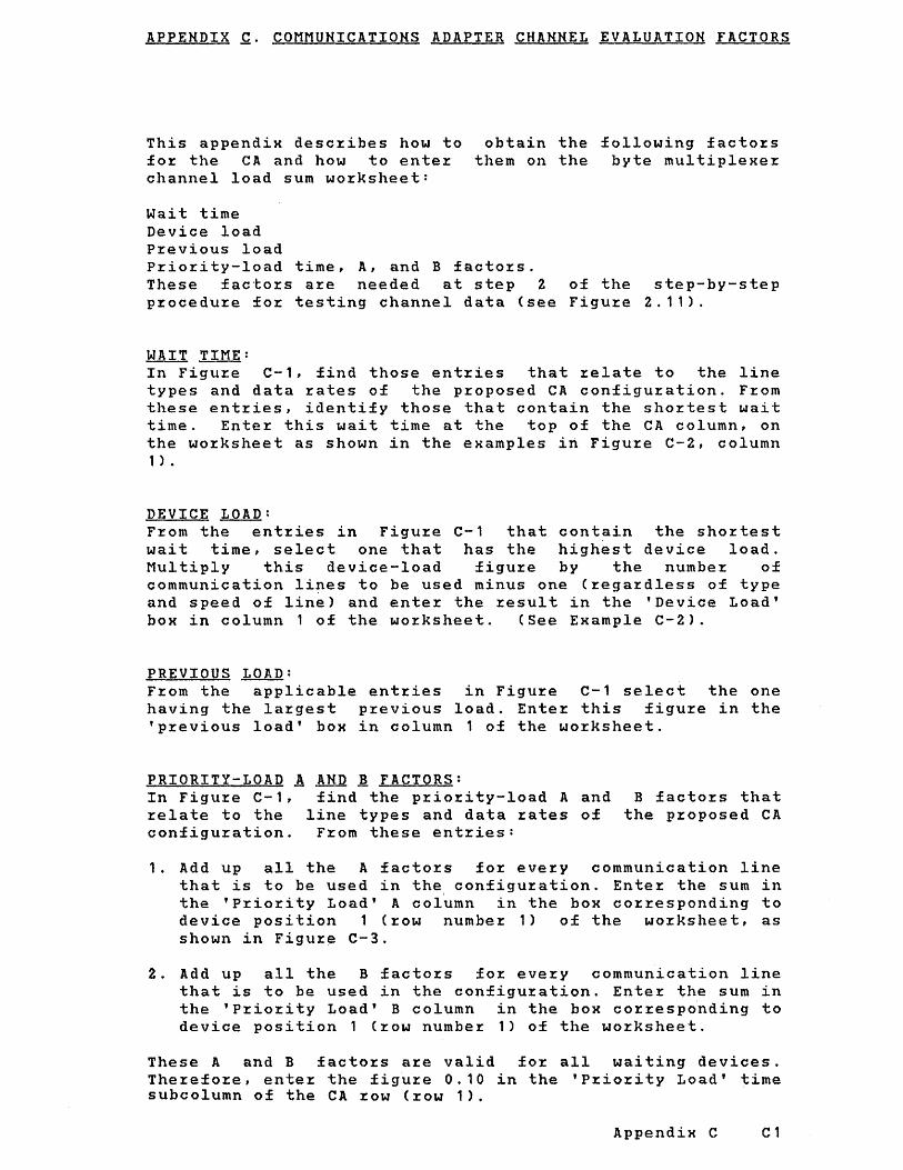
APPENDIX g. COMMUNICATIONS ADAPTER CHANNEL EVALUATION FACTORS
This appendiK describes how to for the CA and how to enter channel load sum worksheet:
obtain the following factors them on the byte multipleKer
Wait time Device load Previous load Priority-load time, A, and B factors. These factors are needed at step 2 of the step-by-step procedure for testing channel data (see Figure 2.11).
WAIT TIME: In Figure C-1, find those entries that relate to the line types and data rates of the proposed CA configuration. From these entries, identify those that contain the shortest wait time. Enter this wait time at the top of the CA column, on the worksheet as shown in the examples in Figure C-2, column 1 ) •
DEVICE LOAD: From the entries in Figure C-1 that contain the shortest wait time, select one that has the highest device load. Multiply this device-load figure by the number of communication lines to be used minus one (regardless of type and speed of line) and enter the result in the 'Device Load' bOK in column 1 of the worksheet. (See EKample C-2).
PREVIOUS LOAD: From the applicable entries in Figure C-1 select the one having the largest previous load. Enter this figure in the 'previous load' bOK in column 1 of the worksheet.
PRIORITY-LOAD A AND ~ FACTORS: In Figure C-1, relate to the configuration.
find the priority-load A and line types and data rates of
From these entries:
B factors that the proposed CA
1. Add up all the A factors for every communication line that is to be used in the, configuration. Enter the sum in the 'Priority Load' A column in the bOK corresponding to device position 1 (row number 1) of the worksheet, as shown in Figure C-3.
2. Add up all the B factors for every communication line that is to be used in the configuration. Enter the sum in the 'Priority Load' B column in the bOK corresponding to device position 1 (row number 1) of the worksheet.
These A and B factors are valid for all waiting devices. Therefore, enter the figure 0.10 in the 'Priority Load' time subcolumn of the CA row (row 1).
AppendiK C C1

------- -------------------------- -------------------------------------------Line Mode of Operation IBit Data IWait ICA ICA Jl:JI:I Priority load control IRate Rate ITime IDev. I Prev. I I
Ib/sec B/sec Ilns ILoad ILoad ITime A I B I ------- ------~-------------I----- ------I-----I-----I---~-I----- -----1-----1 BSC/ with autopolling I 600 75 113.30 I 0.551 0.751 O. 19 11. 611 0.251 SDLC JI: with autopolling I 1200 150 I 6.601 1. 12 1.521 0.19 11. S71 0.501
with autopolling j 2400 300 1 3.251 2.26 3.081 0.19 11. 471 1 .00 I with autopo1lin.g I 3600 450 I 2.151 3.42 4.651 0.19 11. 371 1.50 I with autopollin.g I 4800 600 I 1.60 4.60 6.251 0.19 11. 271 2.001 without autopolling I 480Q 600 I 1. 62 1. 70 6.171 0.19 11.341 1.65 I with Ciutopolling I 7200 900 I 1.03 7.15 9.711 0.19 11. 10 3.00 without autopolling I 7200 900 I 1.06 2.60 9.43 0.19 11.75 2.48 with autopolling I 9600 1200 I 0.75 9.81 13.33 0.19 10.00 8.25
I I 1. i 1 15.50 3.31 without autopolling I 9600 1200 I 0.78 3.54 12.82 O. 19 11.00 3.31 without autopollingi19200 2400 I 0.78 3.54 12.82 0.19 10.35 6.62 without autopollingl56000 7000 I 0.23 12.00 43.50 0.19 7.82 19.32 without autopollingl64000 8000 I 0.20 13.80 2.50 0.19 7.26 22.10
------- --------------------1----- ------1-----SS 1134.5 14.8 167.70 O. 11 0.15 0.19 11.66 0.05
I 300 33.4 130.00 0.25 0.33 0.19 11.65 0.10 I 600 66.7 115.00 0.49 0.67 0.19 11 .63 0.20 11200 133.3 I 7.40 0.99 1.35 0.19 11.59 0.40
* No polling with SDLC lines
** These values are valid if more than one line is used. For a single communication line use Prev.Load= .5/(Wait Time in msec)
Figure C-1: Communication Adapter Channel Evaluation Factors
C2 IBM 4331 Processo~ Channel Cha~acte~istics

IBM 4331
System Identification Waiting Devices (Priority 1= I
Date 1
Device No . CA ... De
Name . 6 .t/,,~~ Na
Wait .~.2.!1. . Wa Priority Load Time Tin
Priority Devices Time A B A". B
Block MPX Channel / Device No ..•••...•..•... Wait time for 2400 BO BSe line Nan.le •.••.•••.....•• , ••.
~
DASD Adapter
Device No ••.••........•.
Name •..•.•...••.....•.•
Byte MPX Channel
Device No ....•••••..•.•.
Nan.le ....... " ..•.......
Ma~netic Tape Adapter
Device No •••.••••••..•..
Name ••..•.•..........•.
• 10 69.68 /.70 (A Sum) (8 Sum)
1 A Sum7 Wait Time =
Device I/..~.Q. ~. Load = r-(1
2 Previous ~'!()8. A~ Load* = Wai
LOAD DeIA SUMt = Loa
3 Pre
.... -. LOj -(6 -1) x2.26=Device Load for
2400 BO line
Above ent~ies ~elate to the following configu~ation:
4 sta~t stop lines with 134.5 bps each 1 Bina~y Synch~onous Comun. line with 1200 bps 1 Binary Synchronous Comun. line with 2400 bps
Figure C-2: Example Entries in Load Sum Wo~ksheet For a Typical CA Configuration.
Appendix C C3

1 Associated No. 1 Type of Line 1 A-Factor 1 B-Factor 1 ----1----------------1----------1----------1
1 I 134.5 bps, SS I 11.66 I .05 I 2 1 134.5 bps, SS 1 11.66 1 .05 I 3 1 134.5 bps, SS 1 11.66 1 .05 I 4 1 134.5 bps, SS 1 11.66 1 .05 I 5 1 1200 bps, BSC 1 11.57 I .50 1 6 1 2400 bps, BSC 1 11.47 1 1.00 1
----1----------------1----------1----------1 Totals 69.68 1.70
Figure C-3: Generation of A and B Factors For A Typical CA Configuration
C~ IBM 4331 Processor Channel Characteristics

APPENDIX ~. IBM 2701 DATA ADAPTER UNIT: PRIORITY ASSIGNMENT AND CHANNEL EVALUATION FACTORS
This appendix desc~ibes:
1. How to assign the priority of a 2701 Data Adapter Unit in relation to other devices (including other 2701s) on the byte multiplexer channel.
2. How to enter 2701 priority information on the byte multiplexe~ channel load sum wo~ksheet. This information is needed at step 1 of Figure 2.11 when testing byte multiplexer channel data overrun.
3. How to obtain the following channel evaluation factors for each line connected to a 2701:
Wait time Device load P~evious load P~iority-load time, A, and B factors
This information is needed at steps 2 and/or 3 of Figure 2 . 1 1 •
HOW TO ASSIGN PRIORITY POSITION OF A 2701
A 2701 may serve several communication lines, each with a different wait time. The effective wait time to be used in assigning the priority position of the 2701 relative to other devices on the byte multiplexer channel is determined by:
1. Refer to Figure D-1 and find those entries that relate to the types and speeds of communication lines proposed for the 2701.
2. Choose the ent~y that has the shortest wait time. For example, consider a 2701 that will serve the following communication lines:
IBM Terminal Adapter Type I Model II at 134.5 bps. (Wait time = 63.20 ms.)
IBM Terminal Adapter Type Model II, at 600 bps. (Wait time = 14.20 ms.)
Synchronous Data Adapter Type II, operating with eight-bit code, without autopolling, at 200 bps. (Wait time = 7.70 ms.)
Appendix D Dl

On this 2701, the sho~test wait time is 7.70 ms; this figu~e is used in assigning the prio~ity position of the 2701 as a whole.
HOW TO ENTER 2701 PRIORITY INFORMATION ON LOAD SUM WORKSHEET
In step 1 of Figure 2.11 when testing fo~ byte multiplexe~ channel data overrun, enter 2701 communication lines on the load sum worksheet as if they were individual waiting devices. Make the entries in a continuous block and, within the block, assign decreasing priorities to the communication lines in the order of their increasing wait times; the communication lines with the shorter wait times must get the higher priorities. Figure 0-1 gives wait times for all types and speeds of 2701 communication lines.
Figure 0-2 shows how a typical 2701 communication lines should appear in the columns o£ the load sum worksheet in devices. '
and its attached 'Waiting Devices'
relation to other
HOW TO OBTAIN CHANNEL EVALUATION FACTORES FOR EACH 2701 COMMUNICATION LINE
In steps 2 and/or 3 of Figure 2.11, when testing byte multiplexer channel data overrun, treat each communication line as a separate waiting device; obtain the wait time, device load, p~evious load, and p~io~ity-load time, and A and B factors for each of the 2701 communication lines direct from Figure D-1.
D2 IBM 4331 Processor Channel Characteristics

FeatuJ:es of 2701
IBM TeJ:minal AdapteJ: Type I Model II
IBM TeJ:minal AdapteJ: Type II
IBM TeJ:minal Adaptel: Type III
Synchl:onous Data AdapteJ: Type I
Synchl:onous Data AdapteJ: Type II OpeJ:ating with eight-bit code. without autopolling
PJ:ioJ:ity load Bit J:atelData l:atelWait timeIDevicelpl:eviousl--------------------1
(bps) I (cps) I (ms) Iload Iload I Time I A I B I
134.51 14.801 63.201 0.0871 0.16 I I I I
600 I 66.701 14.201 0.39 I 0.70 I I I I
--------1---------1---------1------1--------600 I 60.001 14.201 0.39 0.70
I I I -------- --------- ---------1------ --------
1200 120.00 8.3010.66 1.20 I
2400 240.00 4.201 1.13 2.38 I
1200 150.00 5.80 0.95 1. 72
2000 250.00 3.50 1. 57 2.86
2400 300.00 2.90 1. 90 3.45
19200 2400.00 0.36 12.40 27.78
40800 5100.00 0.1732.35 58.82
O. 11 17.06 0.11 3.89
0.11 4.31
0.11 2.59 0.11 1 • 19
0.11 1.81 0.11 1.15 O. 11 0.98 O. 11 0.25 O. 11
I O. 14 --------1------
600
1200
2000
2400
3600
4800
7200
19200
40800
50000
75.00
150.00
250.00
300.00
450.00
600.00
900.00 I
2400.001 I
5100.001 I
6250.001 I
25.80 0.21
12.90 0.43
7.70 0.71
6.40 0.86
4.27 1. 29
3.20 1. 72 I
2.13 2.58 I I
0.39 I 0.105 I 3.47
0.78 10.105 I 1.70
1.30 I 0.105
1.56
2.34
3.13
4.69
1.15 ,I 0.1051 0.89 I 0.1051 0.71 0.105 0.57 0.105 0.43
0.81 6.79 I 12.35 0.105 0.25 I
0.38 14.47 I 26.32 I
0.31 17.74 I 32.26 I
0.105 0.20 0.105 0.19
---------1--------- ------1--------
O. 11 7.61 9.0 7.57
9.0 7.58
9.0 7.29 9.0 7.43
0.001 0.081 0.001 0.371
------1 0.001 0.331
------1 0.001 0.661 0.001 1 .321
9.0 0.00 7.51 0.82 9.0 0.00 7.43 1.37 9.0 I 0.00 7.381 1.65 9.0 I 0.00 5.711 13.20 9.0 I 0.00 4.931 28.05
------1------9.5 I 0.00 8.07 0.41 9.5 0.00 8.10 0.82 9.5 0.00 7.92 1.37 9.5 0.00 7.88 1.65 9.5 0.00 7.75 2.47 9.5 0.00 7.63 3.30 9.5 0.00 7.38 4.95 9.5 0 . 0,0 6.14 13.20 9.5 0.001 3.92 28.051 9.5 0.001 4.34 34.471
------1
Figu~e D-1 (Pa~t of 2). 2701 Evaluation Facto~s
Appendix D D3

I Priority load I Features of 2701 IBit rate Data ratelwait timelDevicelPrevious --------------------1
I ( bps) ( cps) I ( m s ) I 10 a d 110 a d Time I A I B I
Synchronous Data Adapter 600 100.00 19.20 0.29 Type II, operating with six-bit code, without 1200 200.00 9.60 0.57 autopolling
2000 333.00 5.70 0.96
2400 400.00 4.801.14
19200 3200.00 0.60 9.17
40800 6800.00 0.28 19.64
50000 8333.00 0.23 23.91
Synchronous Data Adapter 600 60.00 14.20 0.39 Type II, operating with eight-bit code, 1200 150.00 7.10 0.77 with autopolling
Synchronous Data Adapter Type II, operating with six-bit code, with autopolling
Telegraph Adapter Type I
Telegraph Adapter Type II
World Trade Telegraph
World Trade Telegraph Single-Current Adapter
2000 250.00 4.20 1.19
2400 300.00 3.50 1.57
4800 600.001 1.803.05
600
1200
2000
2400
45.5 J
56.9
74.2
110
50
75
50
100.00 10.80 0.51
200.00 5.40 1.01
333.00 3.20 1.72
400.00 2.70 2.04
6.00 141.30 0.04
7.50 113.20 0.05
10.00 86.90 0.06
10.00 85.80 0.06
6.60 128.70 0.04
10.00 85.80 0.06
6.60 128.70 0.04
0.52 0.11 9.5 0.001 2.14 8.32 0.551
1.04 0.11 9.5 0.001 1.40 7.96 1.101
1.75 0.11 9.5 0.001 0.906 7.84 1.83
2.08 0.11 9.5 0.00 0.78 7.79 2.20
16.67 0.11 9.5 0.00 0.23 5.47 17.60
35.71 0.11 9.5 0.00 0.15 3.89 37.40
43.48 0.11 9.5 0.00 I 0.15 I 2.63 45.83
-------- ------1------1------0.70 0.11 I 9.5 0.00
3.49 I 8.06 0.41 1.41 0.11 I 9.5 0.00
1.82 I 8.00 0.82 2.38 0.11 I 9.5 0.00
1.15 7.92 1.37 2.86 0.11 9.5 0.00
0.89 7.88 1.65 5.56 0.11 9.5 0.00
0.93
1. 85
3.13
3.70
0.07
0.09
0.12
0.12
0.08
0.12
0.08
0.57 7.62 3.30
0.11 2.65 0.11 1. 40 0.11 0.906 O. 11 0.78
0.105
0.105
0.105
O. 105
0.105
0.105
0.105
9.5 8.04 9.5 7.96 9.5 7.84 9.5 7.79
9.0
9.0
9.0
9.0
9.0
9.0
9.0
0.00 0.55 0.00 1.10 0.00 1.83 0.00 2.20
0.00
0.00
0.00
0.00
0.00
0.00
0.00
75 10.00\ 85.80 0.06 I 0.12 0.105 9.0 0.00 ------------------------- -------- ---------1--------- ------1--------
Figure D-1 (Part 2 of 2). 2701 Channel Evaluation Factors
D4 ~~. IBM 4331 Processor Channel Characteristics

l
The entries below (for step 1 in Figure 2.11) relate to the following byte-multiplexer channel devices:
1. IBM 2520 Ca~d Read Punch Model B1, ~eading/punching EBCDIC. (Wait time = 1.02 ms.)
2. IBM 2701 Data Adapte~ Unit serving communication lines which use the following ty pes of line cont~ol:
Line 1. IBM Te~minal Adapte~ Type I Model II, at 13~.5
bits/second. (Wait time = 63.20 ms.)
Line 2. Synchronous Data Adapter Type II, Operating with eight-bit code, without autopolling, at 200 bits/second. (Wait time = 7.70 ms.)
Line 3. IBM Terminal Adapte~ Type I Model II at 600 bits/second. (Wait time = 14.20 ms.)
3. IBM 14~2 Card Read Punch Model N1, punching EBCDIC. (Wait time = 11.00 ms.)
Waiting Devices (Priority positions on byte-multiplexer channel)
1 2 3 4 5 I Device No. Z51..0~8~ Device r~o. ~"ot .. Device No. 1..70J Device No. l.10.~ .. Device No. 1-f.l/2~N~ I Name ~~}ff" Name . tll!~. Z ... Name .. t.lN~.] Name .. /./N~ . .t .. Name ·f~~fJJ~· . Wait . J..- .O"l .. Wait .... . 7..70 .. Wait ... . .t'f..ZO Wait .... '.J~"?'.Q . ~i~~ ..... J..~~'()q . Time ... Time Time Time
I B A I B A I B A I B A I B I A I !Y- -----.L 1 - 1 I
\~-------------------------------~,-----------------~' Y Communication lines with shorter wait times are given higher priorities
Figure D-2. Example Showing How the 2701 and its Attached Communication Lines Should Appear in the 'Waiting Devices' Columns of the Load Sum Wo~ksheet
Appendix D D5
B \ ~ ....

This page has been left blank intentionally
D6 IBM 4331 Processor Channel Characteristics

APPENDIX E. IBM 2702 TRANSMISSION CONTROL: PRIORITY ASSIGNMENT AND CHANNEL EVALUATION FACTORS
This appendix desc~ibes:
1. How to assign the prio~ity of a 2702 T~ansmission Cont~ol in ~elation to othe~ devices (including othe~ 2702s) 9n the byte-multiplexe~ channel, fox use in step 1 of Figure 2.11 when testing byte-multiplexer channel data ove~~un.
2. How to obtain the following channel evaluation facto~s of a 2702 for use in steps 2 and/or 3 of Figure 2.11.
Wait time Device load P~evious load P~iotiry-load time, A, and B facto~s.
In this appendix, ~eference is made to the tables of channel evaluation factors given in Figu~es E-1 through E-26. The following guide is included to help the reader find the correct table(s): .
Type of Terminal Control
IBM Terminal Control Type I 75 bps, with autopolling 75 bps, without autopolling
134.5 bps, with autopolling 134.5 bps, without autopolling
600 bps, with autopolling 600 bps, without autopolling
IBM Terminal Control Type II 600 bps, with autopolling 600 bps, without autopolling
Teleg~aph Te~minal Cont~ol I
45.5 bps 56.9 bps 74.2 bps
Teleg~aph Terminal Control Type II 110 bps
Wo~ld Trade Teleg~aph Terminal Cont~ol 50 bps 75 bps 100 bps
Figure
E-1 E-3
£-5 E-7
E-9 E-10
E-11 E-12
E-13 E-15 E-17
E-19
£-21 E-23 E-25
& &
& &
& & &
&
& & &
E-2* £-4*
E-6* E-8*
E-14* E,:-16* E-18*
E-20*
E-22* E-24* E-26*
APPENDIX E E1
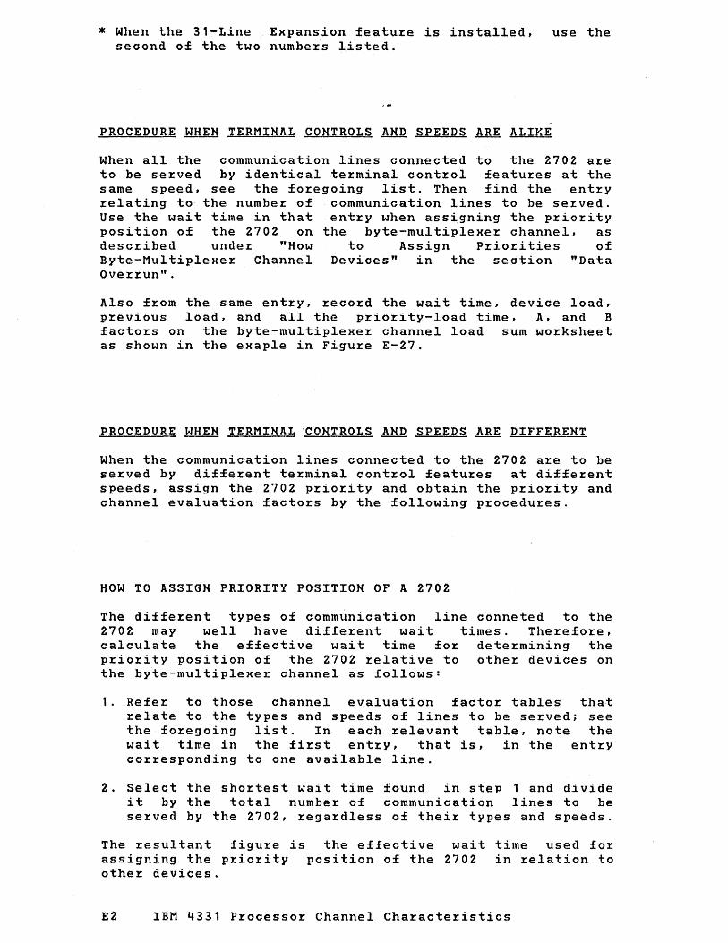
* When the 31-Line Expansion featu%e is installed, use the second of the two numbe%s listed.
PROCEDURE WHEN TERMINAL CONTROLS AND SPEEDS ARE ALIKE
When all the communication lines connected to the 2702 a~e
to be se~ved by identical te~minal cont~ol featu~es at the same speed, see the fo~egoing list. Then find the ent~y
~elating to the numbe% of communication lines to be se~ved. Use the wait time in that entry when assigning the prio~ity position of the 2702 on the byte-multiplexe~ channel, as described under "How to Assign Prio~ities of Byte-Multiplexer Channel Devices" in the section "Data Over~un".
Also f~om the same entry, ~eco~d the wait time, device load, previous load, and all the p~iority-Ioad time, A, and B facto~s on the byte-multiplexe~ channel load sum worksheet as shown in the exaple in Figure E-27.
PROCEDURE WHEN TERMINAL 'CONTROLS AND SPEEDS ARE DIFFERENT
When the communication lines connected to the 2702 a~e to be served by dif£e~ent te~minal control featu~es at diffe~ent speeds, assign the 2702 p~io~ity and obtain the p~io~ity and channel evaluation factors by the following p~ocedu~es.
HOW TO ASSIGN PRIORITY POSITION OF A 2702
The diffe~ent types of communication line conneted to the 2702 may well have different wait times. The~efore,
calculate the effective wait time for determining the p~iority position of the 2702 ~elative to other devices on the byte-multiplexer channel as follows:
1. Refe~ to those channel evaluation factor tables that ~elate to the types and speeds of lines to be served; see the fo~egoing list. In each relevant table, note the wait time in the fi~st ent~y, that is, in the entry co~~esponding to one available line.
2. Select the sho~test wait time found in step 1 and d~vide it by the total numbe~ of communication lines to be se~ved by the 2702, rega~dless of thei~ types and speeds.
The resultant figure is the effective wait time used fo~ assigning the priority position of the 2702 in ~elation to othe~ devices.
E2 IBM 4331 Processo~ Channel Cha~acte~istics

Fo~ example, conside~ a 2702 that will se~ve the following communication lines:
Lines 1 through 10, IBM Te~minal Cont~ol Type II, at 75 bps, with autopolling, without the 31-line expansion featu~e.
Lines 11 through 15, IBM Terminal Cont~ol Type II, bps, with autopolling.
at 600
F~om Figures E1 and E11, the "one available line" wait times are 115.66ms and 14.38 ms ~espectively. The total number of cummunication lines is 15. The effective wait time - used only for assigning a priority position to the 2702 - is, therefore, 14.38 divided by 15 = .958ms.
HOW TO OBTAIN CHANNEL EVALUATION FACTORS OF A 2702
1. Refe~ to the channel evaluation facto~ table that yielded the shortest "one available line" wait time, as described in "How to Assign P~iority Position of 2702". In this table, find the entry that corresponds to the total number of lines being served by the 2702 - regardless of their type and speed.
2. From this entry, take the wait time, device load, previous load, and priority-load time, A and B factors for use in steps 2 and/or of Figure 2.11 when testing for byte-multiplexer channel data overrun.
For instance, to obtain the channel for the 2702 desribed in the previous Figure E-11 because this table yielded available line" wait time. From this factors belonging to the 15-line entry.
evaluation factors example, refer to the shortest "one table, take the
APPENDIX E [3

LINE WAIT DEVICE PREY. PRIORITY - LOAD NO. TIME LOAD LOAD TIME A B
1 115.664 .078 .086 .100 9.000 10.742 .535 14.747 .046
2 57.584 . 156 . 174 .100 7.418 17.578 • .758 12.597 10.742
1.527 28.860 .092 3 38.384 .234 .261 .100 7.418 17.578
1.320 16.440 10.742 2.519 43.154 . 137
4 28.784 .313 .347 .100 7.418 17.578 1.882 20.284 10.742
5 23.024 .391 .434 .100 7.418 17.578 2.444 24.128 10.742 4.503 71.468 .229
6 19.184 .469 .521 .100 7.418 17.578 3.007 27.972 10.742 5.495 85.489 .275
7 16.304 .552 .613 .100 7.418 17.578 3.569 31.815 10.742 6.487 99.419 .321
8 14.384 .626 .695 .100 7.418 17.578 4.131 35.659 10.742 7.479 113.258 .367
9 12.464 .722 .802 .100 7.418 17.578 4.694 39.503 10.742 8.471 127.006 .412
10 11 .504 .782 .869 .100 7.418 17.578 5.256 43.347 10.742 9.463 140.663 .458
1 1 10.064 .894 .994 .100 7.418 17.578 5.818 47.190 10.742
10.455 154.229 .504 12 9.584 .939 1 .043 . 100 7.418 17.578
6.380 51.034 10.742 11.447 167.704 .550
13 8.624 1 .044 1 • 160 .100 7.418 17.578 6.943 54.878 10.742
12.439 181.088 .596 14 8.144 1 .105 1 .228 .100 7.418 17.578
7.505 58.722 10.742 13.431 194.382 .642
15 7.664 1.174 1 .305 .100 7.418 17.578 8.067 62.565 10.742
14.423 207.584 .687
Figure E-1: 2702 Channel Evaluation Factors, IBM Terminal Control Type I (75 bps), with Autopolling, without 31-Line Expansion
E4 IBM 4331 Processor Channel Characteristics

LINE WAIT DEVICE PREY. PRIORITY - LOAD NO. TIME LOAD LOAD TIME A B
1 115.056 .078 .087 .100 9.000 5.371 1 .047 14.624 .046
2 57.520 • 156 • 1 74 .100 8.209 8.789 1.270 12.548 5.371 3.063 28.719 .092
3 37.680 .239 .265 .100 8.209 8.789 2.344 16.220 5.371 5.079 42.802 . 137
4 28.752 .313 .348 .100 8.209 8.789 3.418 19.892 5.371 7.095 56.699 • 183
5 22.800 .395 .439 .100 8.209 8.789 4.492 23.564 5.371 9. 111 70.412 .229
6 18.832 .478 .531 .100 8.209 S.789 5.567 27.236 5.371
11.127 83.940 .275 7 15.856 .568 .631 .100 8.209 8.789
6.641 30.90S 5.371 13.143 97.283 .321
8 13.872 .649 .721 .100 8.209 8.789 7.715 34.580 5.371
15.159 110.442 .367 9 11.888 .757 .841 .100 8.209 8.789
8.790 38.251 5.371 17.175 123.415 .412
10 10.896 .826 .918 .100 8.209 8.789 9.864 41.923 5.371
19.191 136.204 .458 1 1 9.904 .909 1.010 .100 8.209 8.789
10.938 45.595 5.371 21 .207 148.808 .504
12 8.912 1 .010 1 • 122 .100 8.209 8.789 12.012 49.267 5.371 23.223 161.227 .550
13 7.920 1 • 136 1 .263 .100 8.209 8.789 13.087 52.939 5.371 25.239 173.462 .596
14 7.920 1.136 1 .263 .100 8.209 8.789 14.161 56.611 5.371 27.255 185.511 .642
15 6.928 1 .299 1.443 .100 8.209 8.789 15.235 60.283 5.371 29.271 197.376 .687
16 6.928 1.299 1.443 .100 8.209 8.789 16.310 63.955 5.371 31.287 209.056 .733
Figu~e E-2: 2702 Channel Evaluation Facto~s, IBMTe~minal Cont~ol Type I (75 bps), with Autopolling, with 31-Line Expansion (pa~t 1 of 2)
APPENDIX E ;5
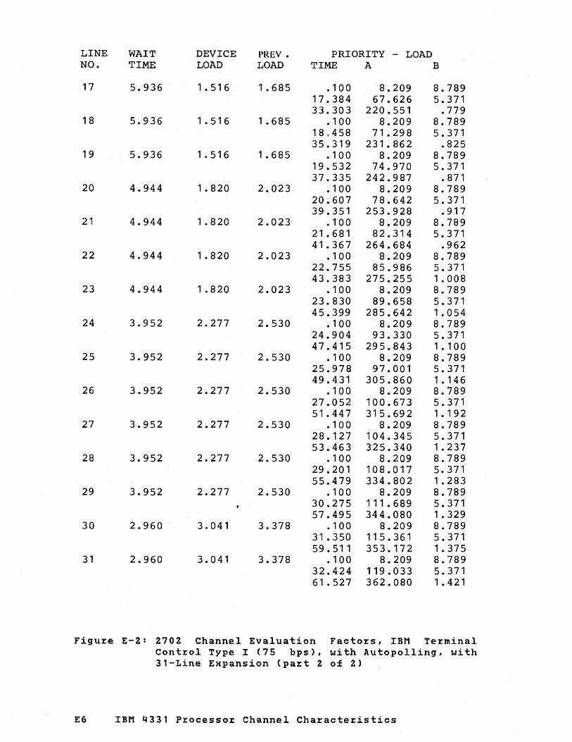
LINE WAIT DEVICE PREV. PRIORITY - LOAD NO. TIME LOAD LOAD TIME A B
17 5.936 1.516 1 .685 .100 8.209 8.789 17.384 67.626 5.371 33.303 220.551 .779
18 5.936 1 .516 1 .685 .100 8.209 8.789 18,458 71.298 5.371 35.319 231.862 .825
19 5.936 1 • 516 1 .685 .100 8.209 8.789 19.532 74.970 5.371 37.335 242.987 .871
20 4.944 1.820 2.023 .100 8.209 8.789 20.607 78.642 5.371 39.351 253.928 .917
21 4.944 1.820 2.023 .100 8.209 8.789 21.681 82.314 5.371 41.367 264.684 .962
22 4.944 1.820 2.023 .100 8.209 8.789 22.755 85.986 5.371 43.383 275.255 1.008
23 4.944 1.820 2.023 .100 8.209 8.789 23.830 89.658 5.371 45.399 285.642 1.054
24 3.952 2.277 2.530 .100 8.209 8.789 24.904 93.330 5.371 47.415 295.843 1 . 100
25 3.952 2.277 2.530 .100 8.209 8.789 25.978 97.001 5.371 49.431 305.860 1 • 146
26 3.952 2.277 2.530 • 100 8.209 8.789 27.052 100.673 5.371 51.447 315.692 1.192
27 3.952 2.277 2.530 .100 8.209 8.789 28.127 104.345 5.371 53.463 325.340 1.237
28 3.952 2.277 2.530 .100 8.209 8.789 29.201 108.017 5.371 55.479 334.802 1 .283
29 3.952 2.277 2.530 • 100 8.209 8.789 30.275 111.689 5.371 57.495 344.080 1 .329
30 2.960 3.041 3.378 .100 8.209 8.789 31 • 350 115.361 5.371 59.511 353.172 1.375
31 2.960 3.041 3.378 .100 8.209 8.789 32.424 119.033 5.371 61.527 362.080 1 .421
Figure E-2: 2702 Channel Evaluation Factors, IBM Terminal Control Type I (75 bps), with Autopolling, with 31-Line Expansion (part 2 of 2)
E6 IBM 4331 Processor Channel Characteristics

LINE WAIT DEVICE PREY. PRIORITY - LOAD NO. TIME LOAD LOAD TIME A B
1 115.664 .048 .086 .100 9.000 .046 2 57.584 .096 • 174 .100 7.418 17.578
.602 17.945 .092 3 38.384 • 143 .261 .100 7.418 17.578
1 • 11 4 26.847 • 137 4 28.784 • 191 .347 .100 7.418 17.578
1.626 35.702 • 183 5 23.024 .239 .434 .100 7.418 17.578
2.138 44.510 .229 6 19.184 .287 .521 .100 7.418 17.578
2.650 53.271 .275 7 16.304 .337 .613 .100 7.418 17.578
3.162 61.986 .321 8 14.384 .382 .695 .100 7.418 17.578
3.674 70.653 .367 9 12.464 .441 .802 .100 7.418 17.578
4.186 79.273 .412 10 11.504 .478 .869 • 100 7.418 17.578
4.698 87.847 .458 1 1 10.064 .547 .994 .100 7.418 17.578
5.210 96.373 .504 12 9.584 .574 1.043 .100 7.418 17.578
5.722 104.853 .550 13 8.624 .638 1 • 160 .100 7.418 17.578
6.234 113.286 .596 14 8.144 .675 1.228 .100 7.418 17.578
6.746 121.671 .642 15 7.664 .718 1 .305 .100 7.418 17.578
7.258 130.010 .687
Figu~e E-3: 2702 Channel Evaluation Facto~s, IBM Te~minal Cont~ol Type I (75 bps), without Autopolling, without 31-Line Expansion
APPENDIX E E7

LINE WAIT DEVICE PREY. PRIORITY - LOAD NO. TIME LOAD LOAD TIME A B
1 115.056 .048 .087 .100 9.000 .046 2 57.520 .096 • 174 .100 8.209 8.789
1 . 114 17.898 .092 3 37.680 • 146 .265 .100 8.209 8.789
2. ,13 8 26.706 • 137 4 28.752 • 191 .348 .100 8.209 8.789
3.162 35.420 . 183 5 22.800 .241 .439 • 100 8.209 8.789
4.186 44.041 .229 6 18.832 .292 .531 .100 8.209 8.789
5.210 52.567 .275 7 15.856 .347 .631 • 100 8.209 8.789
6.234 61.000 .321 8 13.872 .396 .721 .100 8.209 8.789
7.258 69 .339 .367 9 11 .888 .463 .841 · 100 8.209 8.789
8.282 77.584 .412 10 10.896 .505 .918 • 100 8.209 8.789
9.306 85.735 .458 1 1 9.904 .555 1.010 • 100 8.209 8.789
10.330 93.792 .504 12 8.912 .617 1 • 122 .100 8.209 8.789
11.354 101.755 .550 13 7.920 .694 1.263 .100 8.209 8.789
12.378 109.625 .596 14 7.920 .694 1.263 .100 8.209 8.789
13.402 117.400 .642 15 6.928 .794 1.443 · 100 8.209 8.789
14.426 125.082 .687 16 6.928 .794 1.443 .100 8.209 8.789
15.450 132.670 .738
Figu~e E-4: 2702 Channel Evaluation Facto~s, IBM Te~minal Cont~ol Type I (75 bps), with Autopolling, without 31-Line Expansion (pa~t 1 of 2)
E8 IBM 4331 Processo~ Channel Cha~acteristics

LINE WAIT DEVICE PREY. PRIORITY - LOAD NO. TIME LOAD LOAD TIME A B
17 5.936 .927 1 .685 .100 8.209 8.789 16.474 140.164 .779
18 5.936 .927 1 .685 .100 8.209 8.789 17.498 1-47 • 564 .825
19 5.936 .927 1 .685 .100 8.209 8.789 18.522 154.870 .871
20 4.944 1 • 11 2 2.023 .100 8.209 8.789 19.546 162.083 .917
21 4.944 1 . 11 2 2.023 .100 8.209 8.789 10.570 169.201 .962
22 4.944 1 . 11 2 2.023 .100 8.209 8.789 21.594 176.226 1.008
23 4.944 1 . 11 2 2.023 .100 8.209 8.789 22.618 183.157 1 .054
24 3.952 1 .392 2.530 .100 8.209 8.789 23.642 189.994 1 .100
25 3.952 1 .392 2.530 .100 8.209 8.789 24.666 196.737 1 • 146
26 3.952 1 .392 2.530 .100 8.209 8.789 25.690 203.386 1 • 192
27 3.952 1.392 2.530 .100 8.209 8.789 26.714 209.941 1.237
28 3.952 1.392 2.530 .100 8.209 8.789 27.738 216.403 1.283
29 3.952 1 .392 2.530 .100 8.209 8.789 28.762 222.771 1.329
30 2.960 1.858 3.378 .100 8.209 8.789 29.786 229.044 1.375
31 2.960 1.858 3.378 .100 8.209 8.789 30.810 235.224 1.421
Figu~e E-4: 2702 Channel Evaluation Facto~s, IBM Te~minal Cont~ol Type I (75 bps), with Autopolling, without 31-Line Expansion (pa~t 2 of 2)
APPENDIX E E9

LINE WAIT DEVICE PREY. PRIORITY - LOAD NO. TIME LOAD LOAD TIME A B
1 64.304 • 140 • 156 .100 9.000 10.742 .535 14.747 .082
2 32.144 .280 .311 .100 7.418 17.578 .758 12.597 10.742
1.527 28.749 • 164 3 21.104 .426 .474 .100 7.418 17.578
1.320 16.440 10.742 2.519 42.879 .247
4 15.824 .569 .632 .100 7.418 17.578 1.882 20.284 10.742 3.511 56.846 .329
5 12.464 .722 .802 .100 7.418 17.578 2.444 24.128 10.742 4.503 70.649 .411
6 10.544 .854 .948 .100 7.418 17.578 3.007 27.972 10.742 5.495 84.290 .493
7 9. 104 .989 1 .098 .100 7.418 17.578 3.569 31.815 10.742 6.487 97.768 .575
8 7.664 1 . 174 1 .305 . 100 7.418 17.578 4.131 35.659 10.742 7.479 111.082 .658
9 6.704 1 .342 1.492 .100 7.418 17.578 4.694 39.503 10.742 8.471 124.234 .740
10 6.224 1 .446 1 .607 .100 7.418 17.578 5.256 43.347 10.742 9.463 137.222 .822
1 1 5.744 1.567 1 .741 .100 7.418 17.578 5.818 47.190 10.742
10.455 150.047 .904 12 5.264 1 . 71 0 1 .900 .100 7.418 17.578
6.380 51 .034 10.742 11.447 162.709 .986
13 4.784 1 .881 2.090 .100 7.418 17.578 6.943 54.878 10.742
12.439 175.209 1.069 14 4.304 2.091 2.323 .100 7.418 17.578
7.505 58.722 10.742 13.431 187.545 1 • 151
15 3.824 2.354 2.615 .100 7.418 17.578 8.067 62.565 10.742
14.423 199.718 1 .233
Figure E-5: 2702 Channel Evaluation Factors, IBM Terminal Control Type I (134.5 bps), with Autopolling, without 31-Line Expansion
E10 IBM 4331 P%ocessor Channel Characteristics

LINE WAIT DEVICE PREV. PRIORITY - LOAD NO. TIME LOAD LOAD TIME A B
1 64.464 • 140 • 155 .100 9.000 5.371 1.047 14.624 .082
2 31.728 .284 .315 .100 8.209 8.789 1.270 12.548 5.371 3.063 28.496 • 164
3 20.816 .432 .480 .100 8.209 8.789 2.344 16.220 5.371 5.079 42.248 .247
4 15.856 .568 .631 .100 8.209 8.789 3.418 19.892 5.371 7.095 55.667 .329
5 12.880 .699 .776 .100 8.209 8.789 4.492 23.564 5.371 9. 111 68.756 .411
6 9.904 .909 1 .010 .100 8.209 8.789 5.567 27.236 5.371
11.127 81.513 .493 7 8.912 1 .010 1.122 .100 8.209 8.789
6.641 30.908 5.371 13.143 93.938 .575
8 7.920 1 • 136 1 .263 .100 8.209 8.789 7.715 34.580 5.371
15.159 106.032 .658 9 6.928 1 .299 1 .443 .100 8.209 8.789
8.790 38.251 5.371 17.175 117.795 .740
10 5.936 1 .516 1 .685 . 100 8.209 8.789 9.864 41.923 5.371
19.191 129.226 .822 1 1 4.944 1 .820 2.023 .100 8.209 8.789
10.938 45.595 5.371 21.207 140.326 .904
12 4.944 1.820 2.023 .100 8.209 8.789 12.012 49.267 5.371 23.223 151.094 .986
13 4.944 1 .820 2.023 .100 8.209 8.789 13.087 52.939 5.371 25.239 161.531 1 .069
14 3.952 2.277 2.530 • 100 8.209 8.789 14.161 56.611 5.371 27.255 171.637 1 • 151
15 3.952 2.277 2.530 .100 8.209 8.789 15.235 60.283 5.371 29.271 181.411 1.233
16 3.952 2.277 2.530 .100 8.209 8.789 16.310 63.955 5.371 31 .287 190.854 1 .315
Figure E-6: 2702 Channel Evaluation Factors, IBM Terminal Control Type I ( 134.5 bps) , with Autopolling, with 31-Line Expansion (part 1 of 2)
APPENDIX E E11

LINE WAIT DEVICE PREV. PRIORITY - LOAD NO. TIME LOAD LOAD TIME A B
17 2.960 3.041 3.378 .100 8.209 8.789 17.384 67.626 5.371 33.303 199.966 1.397
18 2.960 3.041 3.378 .100 8.209 8.789 18.458 71.298 5.371 35.319 208.746 1.479
19 2.960 3.041 3.378 .100 8.209 8.789 19.532 74.970 5.371 37.335 217.194 1 • 562
20 2.960 3.041 3.378 .100 8.209 8.789 20.607 78.642 5.371 39.351 225.311 1 • 644
21 2.960 3.041 3.378 .100 8.209 8.789 21 .681 82.314 5.371 41.367 233.097 1 .726
22 1 .968 4.573 5.081 .100 8.209 8.789 22.755 85.986 5.371 43.383 240.551 1.808
23 1 .968 4.573 5.081 • 100 8.209 8.789 23.830 89.658 5.371 45.399 247.674 1 • 890
24 1 .968 4.573 5.081 .100 8.209 8.789 24.904 93.330 5.371 47.415 254.466 1.973
25 1.968 4.573 .5.081 .100 8.209 8.789 25.978 97.001 5.371 49.431 260.926 2.055
26 1.968 4.573 5.081 .100 8.209 8.789 27.052 100.673 5.371 51.447 267.055 2.137
27 1.968 4.573 5.081 .100 8.209 8.789 28.127 104.345 5.371 53.463 272.852 2.219
28 1 .968 4.573 5.081 .100 8.209 8.789 29.201 108.017 5.371 55.479 278.318 2.301
29 1.968 4.573 5.081 .100 8.209 8.789 30.275 111.689 5.371 57.495 283.453 2.384
30 1.968 4.573 5.081 .100 8.209 8.789 31.350 115.361 5.371 59.511 288.256 2.466
31 1.968 4.573 5.081 .100 8.209 8.789 32.424 119.033 5.371 61.527 292.727 2.548
Figuze E-6: 2702 Channel Evaluation Factozs, IBM Tezminal Contzol Type I (134.5 bps), with Autopolling, with 31-Line Expansion (pazt 2 of 2)
E12 IBM 4331 Pzocessoz Channel Chaxactexistics
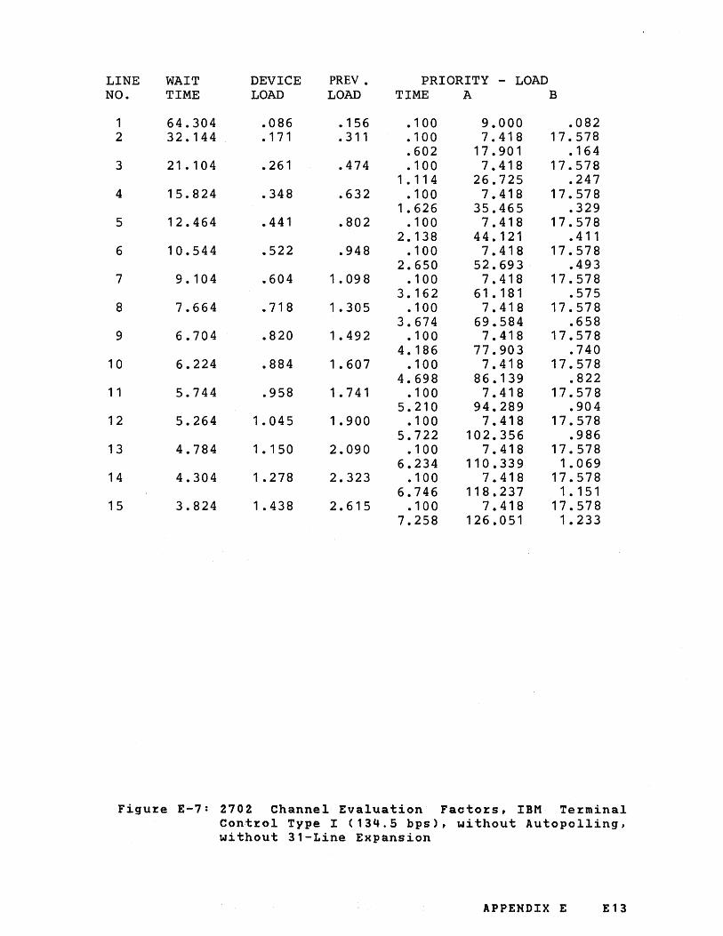
LINE WAIT DEVICE PREV. PRIORITY - LOAD NO. TIME LOAD LOAD TIME A B
1 64.304 .086 • 156 .100 9.000 .082 2 32.144 . 171 .311 .100 7.418 17.578
.602 17.901 . 164 3 21.104 .261 .474 . 100 7.418 17.578
1 . 11 4 26.725 .247 4 15.824 .348 .632 .100 7.418 17.578
1.626 35.465 .329 5 12.464 .441 .802 .100 7.418 17.578
2.138 44.121 .411 6 10.544 .522 .948 .100 7.418 17.578
2.650 52.693 .493 7 9.104 .604 1 .098 .100 7.418 17.578
3.162 61.181 .575 8 7.664 .718 1 .305 .100 7.418 17.578
3.674 69.584 .658 9 6.704 .820 1.492 • 100 7.418 17.578
4.186 77.903 .740 10 6.224 .884 1.607 .100 7.418 17.578
4.698 86.139 .822 1 1 5.744 .958 1.741 .100 7.418 17.578
5.210 94.289 .904 12 5.264 1.045 1.900 .100 7.418 17.578
5.722 102.356 .986 13 4.784 1.150 2.090 .100 7.418 17.578
6.234 110.339 1.069 14 4.304 1 .278 2.323 .100 7.418 17.578
6.746 118.237 1 • 151 15 3.824 1 .438 2.615 .100 7.418 17.578
7.258 126.051 1.233
Figu~e E-7: 2702 Channel Evaluation Facto~s, IBM Te~minal
Cont~ol Type I (134.5 bps), without Autopolling, without 3l-Line Expansion
APPENDIX E E13
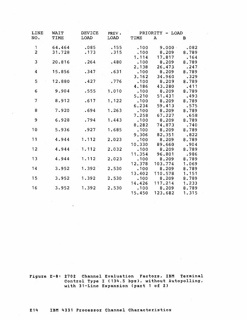
LINE WAIT DEVICE PREV. PRIORITY - LOAD NO. TIME LOAD LOAD TIME A B
1 64.464 .085 • 155 .100 9.000 .082 2 31.728 .173 .315 .100 8.209 8.789
1 • 114 17.817 • 164 3 20.816 .264 .480 .100 8.209 8.789
2.138 26.473 .247 4 15.856 .347 .631 .100 8.209 8.789
3.162 34.960 .329 5 12.880 .427 .776 .100 8.209 8.789
4.186 43.280 .411 6 9.904 .555 1.010 • 100 8.209 8.789
5.210 51.431 .493 7 8.912 .617 1 . 122 • 100 8.209 8.789
6.234 59.413 .575 8 7.920 .694 1 .263 .100 8.209 8.789
7.258 67.227 .658 9 6.928 .794 1 .443 .100 8.209 8.789
8.282 74.873 .740 10 5.936 .927 1.685 .100 8.209 8.789
9.306 82.351 .822 1 1 4.944 1 . 112 2.023 .100 8.209 8.789
10.330 89.660 .904 12 4.944 1 . 112 2.032 • 100 8.209 8.789
11.354 96.801 .986 13 4.944 1 • 11 2 2.023 · 100 8.209 8.789
12.378 103.774 1.069 14 3.952 1 .392 2.530 .100 8.209 8.789
13.402 110.578 1 • 1 51 15 3.952 1 .392 2.530 .100 8.209 8.789
14.426 117.214 1.233 16 3.952 1.392 2.530 • 1 00 8.209 8.789
15.450 123.682 1 .31 5
Figu~e E-8: 2702 Channel Evaluation Facto~s, IBM Te~minal Cont~ol Type I (134.5 bps), without Autopolling, with 31-Line Expansion (pa~t 1 of 2)
£14 IBM 4331 P~ocesso~ Channel Cha~acte~istics

LINE WAIT DEVICE PREY. PRIORITY - LOAD NO. TIME LOAD LOAD TIME A B
17 2.960 1 .858 3.378 .100 8.209 8.789 16.474 129.981 1 . 397
18 2.960 1.858 3.378 • 100 8.209 8.789 17.498 136.112 1 .479
19 2.960 1 .858 3.378 · 100 8.209 8.789 18.522 142.074 1 • 562
20 2.960 1 .858 3.378 · 100 8.209 8.789 19.546 147.869 1.644
21 2.960 1 .858 3.378 .10'0 8.209 8.789 10.570 153.494 1.726
22 1 .968 2.795 5.081 • 100 8.209 8.789 21.594 158.952 1.808
23 1.968 2.795 5.081 · 100 8.209 8.789 22.618 164.241 1.890
24 1 .968 2.795 5.081 .100 8.209 8.789 23.642 169.362 1.973
25 1 .968 2.795 5.081 · 100 8.209 8.789 24.666 174.315 2.055
26 1 .968 2.795 5.081 .100 8.209 8.789 25.690 179.099 2.137
27 1 .968 2.795 5.081 .100 8.209 8.789 26.714 183.715 2.219
28 1 .968 2.795 5.081 .100 8.209 8.789 27.738 188.163 2.301
29 1 .968 2.795 5.081 .100 8.209 8.789 28.762 192.442 2.384
30 1 .968 2.795 5.081 . 100 8.209 . 8.789 29.786 196.553 2.466
31 1 .968 2.795 5.081 .100 8.209 8.789 30.810 200.495 2.548
Figure E-8: 2702 Channel Evaluation Factors, IBM Terminal Control Type I (134.5 bps), without Autopolling, with 31-Line Expansion (part 2 of 2)
APPENDIX E E15

LINE WAIT DEVICE PRE V • PRIORITY - LOAD NO. TIME LOAD LOAD TIME A B
1 14.384 .626 .695 .100 9.000 10.742 .535 14.747 .367
2 7.184 1.253 1 .392 .100 7.418 17.578 .758 12.597 10.742
1 • 527 27.880 .733 3 4.784 1 .881 2.090 .100 7.418 17.578
1.320 16.440 10.742 2.519 40.729 1.100
4 3.344 2.691 2.990 • 100 7.418 17.578 1 .882 20.284 10.742 3.511 52.851 1~467
5 2.864 3.142 3.492 .100 7.418 17.578 2.444 24.128 10.742 4.503 64.244 1.833
6 2.384 3.775 4.195 .. 100 7.418 17.578 3.007 27.972 10.742 5.495 74.911 2.200
7 1.904 4.727 5.252 .100 7.418 17.578 3.569 31.815 10.742 6.487 84.850 2.567
8 1.424 6.320 7.022 .100 7.418 17.578 4. 131 35.659 10.742 7.479 94.062 2.933
9 1 .424 6.320 7.022 .100 7.418 17.578 4.694 39.503 10.742 8.471 102.546 3.300
10 1.424 6.320 7.022 • 100 7.418 17.578 5.256 43.347 10.742 9.463 110.302 '3.667
1 1 .944 9.534 10.593 .100 7.418 17.578 10.455 117.331 4.033
12 .944 9.534 10.593 .100 7.418 17.578 6.380 51.034 10.742
11.447 123.633 4.400 13 .944 9.534 10.593 .100 7.418 17.578
6.943 54.878 10.742 12.439 129.207 4.767
14 .944 9.534 10.593 .100 7.418 17.578 7.505 58.722 10.742
13.431 134.054 5.133 15 .944 9.534 10.593 .100 7.418 17.578
8.067 62.565 10.742 14.423 138.174 5.500
Figu~e E-9: 2702 Channel Evaluation Factors, IBM Terminal Control Type I (600 bps), with Autopolling
E16 IBM 4331 P~ocessor Channel Characteristics

LINE WAIT DEVICE PREY. PRIORITY - LOAD NO. TIME LOAD LOAD TIME A B
1 14.384 .382 .695 .100 9.000 .367 2 7. 184 .766 1.392 .100 7.418 17.578
.602 17.559 .733 3 4.784 1 • 150 2.090 . 1 00 7.418 17.578
1 • 114 25.775 1 . 100 4 3.344 1 .645 2.990 .100 7.418 17.578
1 .626 33.615 1.467 5 2.864 1 .920 3.492 .100 7.418 17.578
2.138 41.080 1.833 6 2.384 2.307 4.195 .100 7.418 17.578
2.650 48.170 2.200 7 1.904 2.889 5.252 .100 7.418 17.578
3.162 54.884 2.567 8 1.424 3.862 7.022 .100 7.418 17.578
3.674 61.223 2.933 9 1 .424 3.862 7.022 .100 7.418 17.578
4.186 67.186 3.300 10 1.424 3.862 7.022 .100 7.418 17.578
4.698 72.774 3.667 1 1 .944 5.826 10.593 .100 7.418 17.578
5.210 77.986 4.033 12 .944 5.826 10.593 .100 7.418 17.578
5.722 82.823 4.400 13 .944 5.826 10.593 .100 7.418 17.578
6.234 87.285 4.767 14 .944 5.826 10.593 • 100 7.418 17.578
6.746 91 • 371 5. 133 15 .944 5.826 10.593 .100 7.418 17.578
7.258 95.081 5.500
Figuze E-10: 2702 Channel Evaluation Factozs, IBM Tezminal Contzol Type I (600 bps), without Autopolling
APPENDIX E E17

LINE WAIT DEVICE PREY. PRIORITY - LOAD NO. TIME LOAD LOAD TIME A B
1 14.384 .626 .695 .100 9.000 10.742 .535 14.747 .330
2 7.184 1 .253 1 .392 · 100 7.418 17.578 .758 12.597 10.742
1 • 527 27.992 .660 3 4.784 1.881 2.090 .100 7.418 17.578
1 .320 16.440 10.742 2.519 41.006 .990
4 3.344 2.691 2.990 • 100 7.418 17.578 1.882 20.284 10.742 3. 511 53.365 1 .320
5 2.864 3.142 3.492 .100 7.418 17.578 2.444 24.128 10.742 4.503 65.070 1.650
6 2.384 3.775 4.195 .100 7.418 17.578 3.007 27.972 10.742 5.495 76.120 1.980
7 1.904 4.727 5.252 .100 7.418 17.578 3.569 31.815 10.742 6.487 86.515 2.310
8 1.424 6.320 7.022 • 100 7.418 17.578 4.131 35.659 10.742 7.479 96.255 2.640
9 1 .424 6.320 7.022 .100 7.418 17.578 4.694 39.503 10.742 8.471 105.341 2.970
10 1.424 6.320 7.022 .100 7.418 17.578 5.256 43.347 10.742 9.463 113.772 3.300
1 1 .944 9.534 10.593 • 1 00 7.418 17.578 5.818 47.190 10.742
10.455 121.548 3.630 12 .944 9.534 10.593 .100 7.418 17.578
6.380 51.034 10.742 11.447 128.670 3.960
13 .944 9.534 10.593 • 1 00 7.418 17.578 6.943 54.878 10.742
12.439 135.137 4.290 14 .944 9.534 10.593 .100 7.418 17.578
7.505 58.722 10.742 13.431 140.949 4.620
15 .944 9.534 10.593 • 100 7.418 17.578 8.067 62.565 10.742
14.423 146.106 4.950
Figu~e E-11: 2702 Channel Evaluation Facto~s, IBM Te~minal Cont~ol Type II (600 bps), with Autopolling
E18 IBM 4331 P%ocesso% Channel Cha%acte%istics

LINE WAIT DEVICE PREY. PRIORITY - LOAD NO. TIME LOAD LOAD TIME A B
1 14.384 .382 .695 .100 9.000 .330 2 7.184 .766 1.392 .100 7.418 17.578
.602 17.603 .660 3 4.784 1 • 150 2.090 .100 7.418 17.578
1 • 11 4 25.897 .990 4 3.344 1 .645 2.990 .100 7.418 17.578
1.626 33.854 1.320 5 2.864 1.920 3.492 .100 7.418 17.578
2.138 41.472 1.650 6 2.384 2.307 4.195 .100 7.418 17.578
2.650 48.753 1 .980 7 1.904 2.889 5.252 .100 7.418 17.578
3.162 55.696 2.310 8 1 .424 3.862 7.022 .100 7.418 17.578
3.674 62.301 2.640 9 1.424 3.862 7.022 .100 7.418 17.578
4.186 68.568 2.970 10 1.424 3.862 7.022 . 1 00 7.418 17.578
4.698 74.497 3.300 1 1 .944 5.826 10.593 • 100 7.418 17.578
5.210 80.088 3.630 12 .944 5.826 10 .593 .100 7.418 17.578
5.722 85.341 3.960 13 .944 5.826 10.593 .100 7.418 17.578
6.234 90.256 4.290 14 .944 5.826 10 .593 .100 7.418 17.578
6.746 94.833 4.620 15 .944 5.826 10.593 .100 7.418 17.578
7.258 99.073 4.950
Figure E-12: 2702 Channel Evaluation Factors, IBM Terminal Control Type II (600 bps), without Autopolling
APPENDIX E E19

LINE WAIT DEVICE PREV. PRIORITY - LOAD NO. TIME LOAD LOAD TIME A B
1 159.824 .034 .063 .100 9.000 .031 2 79.664 .069 . 126 .100 7.418 17.578
.602 17.963 .062 3 53.264 .103 . 188 .100 7.418 17.578
1 • 11 4 26.897 .093 4 39.824 . 138 .251 .100 7.418 17.578
1 .626 35.799 · 124 5 31.664 . 174 .316 .100 7.418 17.578
2.138 ' 44. 669 · 155 6 26.384 .208 .379 .100 7.418 17.578
2.650 53.508 · 186 7 22.544 .244 .444 .100 7.418 17.578
3.162 62.315 .217 8 19.664 .280 .509 .100 7.418 17.578
3.674 71.091 .247 9 17.744 .310 .564 .100 7.418 17.578
4.186 79.834 .278 10 15.824 .348 .632 .100 7.418 17.578
4.698 88.547 .309 1 1 14.384 .382 .695 .100 7.418 17.578
5.210 97.227 .340 12 12.944 .425 .773 .100 7.418 17.578
5.722 105.876 .371 13 11 .984 .459 .834 .100 7.418 17.578
6.234 114.493 .402 14 11.024 .499 .907 .100 7.418 17.578
6.746 123.078 .433 15 10.544 .522 .948 .100 7.418 17.578
7.258 131.632 .464
Figu~e E-13: 2702 Channel Evaluation Factozs, Tele~zaph Te~minal Cont~ol Type I (45.5 bps), without 31-Line Expansion
E20 IBM 4331 P~ocesso~ Channel Cha~acte~istics

LINE WAIT DEVICE PREV. PRIORITY - LOAD NO. TIME LOAD LOAD TIME A B
1 159.696 .034 .063 .100 9.000 .031 2 79.344 .069 . 126 .100 8.209 8.789
1 • 11 4 17.931 .062 3 52.560 .105 . 190 .100 8.209 8.789
2.138 26.802 .093 4 39.664 • 139 .252 .100 8.209 8.789
3.162 35.609 • 124 5 31.728 • 173 .315 • 100 8.209 8.789
4.186 44.352 • 155 6 25.776 .213 .388 .100 8.209 8.789
5.210 53.033 • 186 7 22.800 .241 .439 .100 8.209 8.789
6.234 61.650 .217 8 19.824 .277 .504 .100 8.209 8.789
7.258 70.204 .247 9 16.848 .326 .594 .100 8.209 8.789
8.282 78.694 .278 10 15.856 .347 .631 .100 8.209 8.789
9.306 87.121 .309 1 1 13.872 .396 .721 .100 8.209 8.789
10.330 95.485 .340 12 12.880 .427 .776 .100 8.209 8.789
11.354 103.785 .371 13 11.888 .463 .841 .100 8.209 8.789
12.378 112.022 .402 14 10.896 .505 .918 .100 8.209 8.789
13.402 120.195 .433 15 9.904 .555 1 .010 .100 8.209 8.789
14.426 128.305 .464 16 9.904 .555 1.010 .100 8.209 8.789
15.450 136.352 .495
Figu~e E-14: 2702 Channel Evaluation Facto~s, Teleg~aph Te~minal Cont~ol Type I (45.5. bps), wi th 31-Line Expansion (pa~t 1 of Z)
APPENDIX E E21

LINE WAIT DEVICE PREV. PRIORITY - LOAD NO. TIME LOAD LOAD TIME A B
17 8.912 .617 1 • 122 .100 8.209 8.789 16.474 144.336 .526
18 7.920 .694 1.263 .100 8.209 8.789 17.498 152.256 .557
19 7.920 .694 1.263 . 100 8.209 8.789 18.522 160.113 .588
20 7.920 .694 1 .263 .100 8.209 8.789 19.546 167.906 .619
21 6.928 .794 1 .443 .100 8.209 8.789 20.570 175.636 .650
22 6.928 .794 1 .443 .100 8.209 8.789 21.594 183.303 .681
23 6.928 .794 1 .443 .100 8.209 8.789 22.618 190.906 .712
24 5.936 .927 1.685 .100 8.209 8.789 23.642 198.446 .742
25 5.936 .927 1 .685 .100 8.209 8.789 24.666 205.922 .773
26 5.936 .927 1 .685 .100 8.209 8.789 25.690 213.336 .804
27 4.944 1 . 112 2.023 .100 8.209 8.789 26.714 220.685 .835
28 4.944 1 . 11 2 2.023 .100 8.209 8.789 27.738 227.972 .866
29 4.944 1 . 112 2.023 .100 8.209 8.789 28.762 235.195 .897
30 4.944 1 • 1 1 2 2.023 .100 8.209 8.789 29.786 242.355 .928
31 4.944 1 . 112 2.023 .100 8.209 8.789 30.810 249.451 .959
Figu~e E-14: 2702 Channel Evaluation Factors, Telegraph Terminal Control Type I (45.5 bps), with 31-Line Expansion (pa~t 2 of 2)
E22 IBM 4331 P~ocesso~ Channel Cha~acte~istics
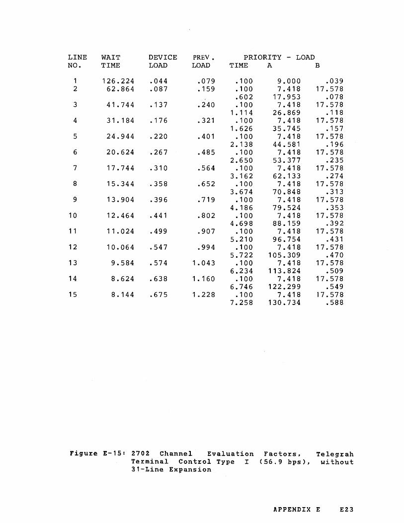
LINE WAIT DEVICE PREY. PRIORITY - LOAD NO. TIME LOAD LOAD TIME A B
1 126.224 .044 .079 .100 9.000 .039 2 62.864 .087 • 159 .100 7.418 17.578
.602 17.953 .078 3 41.744 . 137 .240 . 100 7.418 17.578
1 • 11 4 26.869 • 11 8 4 31.184 .176 .321 .100 7.418 17.578
1.626 35.745 · 157 5 24.944 .220 .401 .100 7.418 17.578
2.138 44.581 · 196 6 20.624 .267 .485 .100 7.418 17.578
2.650 53.377 .235 7 17.744 .310 .564 .100 7.418 17.578
3.162 62.133 .274 8 15.344 .358 .652 .100 7.418 17.578
3.674 70.848 .313 9 13.904 .396 .719 .100 7.418 17.578
4.186 79.524 .353 10 12.464 .441 .802 .100 7.418 17.578
4.698 88.159 .392 1 1 11.024 .499 .907 .100 7.418 17.578
5.210 96.754 .431 12 10.064 .547 .994 .100 7.418 17.578
5.722 105.309 .470 13 9.584 .574 1.043 .100 7.418 17.578
6.234 113.824 .509 14 8.624 .638 1 • 160 .100 7.418 17.578
6.746 122.299 .549 15 8.144 .675 1.228 .100 7.418 17.578
7.258 130.734 .588
Figu~e E-15: 2702 Channel Evaluation Facto~s, Teleg~ah Te~minal Cont~ol Type I (56.9 bps), without 31-Line Expansion
APPENDIX E E23

LINE WAIT DEVICE PREV. PRIORITY - LOAD NO. TIME LOAD LOAD TIME A B
1 125.968 .044 .079 .100 9.000 .039 2 62.480 .088 • 160 .100 8.209 8.789
1 • 11 4 17.913 .078 3 41.648 .132 .240 · 100 8.209 8.789
2. 138 26.749 · 11 8 4 30.736 .179 .325 · 190 8.209 8.789
3.162 35.504 · 157 5 24.784 .222 .403 .100 8.209 8.789
4.186 44.180 · 196 6 20.816 .264 .480 • 100 8.209 8.789
5.210 52.775 .235 7 17.840 .308 .561 .100 8.209 8.789
6.234 61.290 .274 8 14.864 .370 .673 · 100 8.209 8.789
7.258 69.725 .313 9 13.872 .396 .721 .100 8.209 8.789
8.282 78.079 .353 10 11.888 .463 .841 .100 8.209 8.78Q
9.306 86.353 .392 1 1 10.896 .505 .918 .100 8.209 8.789
10.330 94.547 .431 12 9.904 .555 1 .010 .100 8.209 8.789
11.354 102.661 .470 "13 8.912 .617 1 . 122 .100 8.209 8.789
12.378 110.694 .509 14 8.912 .617 1 • 122 · 100 8.209 8.789
13.402 118.647 .549 15 7.920 .694 1 . 263 .100 8.209 8.789
14.426 126.520 .588 16 6.928 .794 1 .443 · 1 00 8.209 8.789
15.450 134.313 .627
Figure E-16: 2702 Channel Evaluation Factors, Telegraph Terminal Control Type I (56.9 bps), with 31-Line Expansion (part 1 of 2)
E24 IBM 4331 Processor Channel Characteristics

LINE WAIT DEVICE PREY • PRIORITY - LOAD NO. TIME LOAD LOAD TIME A B
17 6.928 .794 1 .443 • 100 8.209 8.789 16.47:4 142.025 .866
18 6.928 .794 1 .443 • 1 0 ~ 8.209 8.789 17.498 149.657 .705
19 5.936 .927 1 .685 · 100 , 8.209 8.789 18.522 157.209 .745
20 5.936 .927 1.685 · 100 '. 8.209 8.789 19.546 164.681 .784
21 5.936 .927 1 .685 .100 8.209 8.789 20.570 172.072 .823
22 4.944 1 . 11 2 2.023 .100 8.209 8.789 21 • 594 179.383 .862
23 4.944 1 . 1 1 2 2.023 · 100 ,,8.209 8.789 22.618 186.614 .901
24 4.944 1 . 11 2 2.023 · 100 8.209 8.789 23.642 193.765 .940
25 4.944 1 . 11 2 2.023 · 100 8.209 8.789 24.666 200.835 .980
26 3.952 1 .392 2.530 • 100 8.209 8.789 25.690 207.825 1.019
27 3.952 1 .392 2.530 .100 8.209 8.789 26.714 214.735 1 .058
28 3.952 1 .392 2.530 · 100 8.209 8.789 27.738 221.564 1.097
29 3.952 1.392 2.530 .100 8.209 8.789 28.762 228.314 1 • 1 36
30 3.952 1 .392 2.530 • 100 8.209 8.789 29.786 234.983 1 . 176
31 3.952 1 .392 2.530 · 100 8.209 8.789 30.810 241.572 1.215
Figuze E-16; 2702 Channel Evaluation Facto~s, Teleg~aph Tezminal Cont~ol Type I (56.9 bps), with 31-Line Expansion (pa~t 2 of 2)
APPENDIX E E25

LINE WAIT DEVICE PREV. PRIORITY - LOAD NO. TIME LOAD LOAD TIME A B
1 95.984 .057 .104 • 1 00 9.000 .052 2 47.984 . 11 5 .208 .100 7.418 17.578
.602 17.938 • 103 3 31.664 .174 .316 · 100 7.418 17.578
1 • 11 4 26.828 . 155 4 23.984 .229 .417 .100 7.418 17.578
1.626 35.665 .206 5 19.184 .287 .521 .100 7.418 17.578
2.138 44.449 .258 6 15.824 .348 .632 .100 7.418 17.578
2.650 53.180 .309 7 13.424 .410 .745 · 100 7.418 17.578
3. 162 61 .859 .361 8 11.984 .459 .834 .100 7.418 .17.578
3.674 70.484 .412 9 10.544 .522 .948 • 100 7.418 17.578
4.186 79.057 .464 10 9.584 .574 1.043 .100 7.418 17.578
4.698 87.578 .516 1 1 8.624 .638 1 . 160 • 100 7.418 17.578
5.210 96.045 .567 12 7.664 .718 1 .305 .100 7.418 17.578
5.722 104.460 .619 13 7.184 .766 1 .392 .100 7.418 17.578
6.234 112.821 .670 14 6.704 .820 1 .492 .100 7.418 17.578
6.746 121.130 .722 15 6.224 .884 1.607 .100 7.418 17.578
7.258 129.386 .773
Figure E-17: 2702 Channel Evaluation Factors, Telegraph Terminal Control Type I (74.2 bps), without 31-Line Expansion
E26 IBM 4331 Processor Channel Characteristics

LINE WAIT DEVICE PREV. PRIORITY - LOAD NO.
1 2
3
4
5
6
7
8
9
10
1 1
12
13
14
15
16
TIME LOAD LOAD TIME A B
95.216 .058 .105 • 100 9.000 .052 47.600 • 11 6 .210 .100 8.209 8.789
1 • 114 17.885 .103 31.728 .173 .315 .100 8.209 8.789
2.138 26.669 . 155 23.792 .231 .420 .100 8.209 8.789
3.162 35.348 .206 18.832 .292 .531 .100 8.209 8.789
4.186 43.921 .258 15.856 .347 .631 .100 8.209 8.789
5.210 52.388 .309 12.880 .427 .776 .10 8.209 8.789
6.234 60.750 .361 11.888 .463 .841 .100 8.209 8.789
7.258 69.006 .412 9.904 .555 1.010 .100 8.209 8.789
8.282 77.157 .464 8.912 .617 1.122 .100 8.209 8.789
9.306 85.202 .516 7.920 .694 1.263 .100 8.209 8.789
10.330 93.141 .567 7.920 .694 1.263 .100 8.209 8.789
11.354 100.975 .619 6.928 .794 1.443 · 100 8.209 8.789
12.378 108.703 .670 5.936 .927 1.685 .100 8.209 8.789
13.402 116.325 .722 5.936 .927 1.685 • 100 8.209 8.789
14.426 123.842 .773 5.936 .927 1.685 • 100 8.209 8.789
15.450 131.254 .825
Figure E-18: 2702 Channel Evaluation Factors, Telegraph Terminal Control Type I (74.2 bps), with 31-Line Expansion (part 1 of 2)
APPENDIX E E27

LINE WAIT DEVICE PREV. PRIORITY - LOAD NO. TIME LOAD LOAD TIME A B
17 4.944 '1.112 2.023 .100 8.209 8.789 16.474 138.560 .877
18 4.944 1 • 11 2 2.023 .10'0 8.209 8.789 17.498 145.760 .928
19 4.944 1 • 11 2 2.023 .100 8.209 8.789 18.522 152.854 .980
20 3.952 1.392 2.530 .100 8.209 8.789 19.546 159.843 1 .031
21 3.952 1.392 2.530 .100 8.209 8.789 20.570 166.727 1 .083
22 3.952 1.392 2.530 .100 8.209 8.789 21.594 173.504 1 • 134
23 3.952 1 .392 2.530 .100 8.209 8.789 22.618 180.176 1.186
24 3.952 1.392 2.530 .100 8.209 8.789 23.642 186.743 1 .237
25 2.960 1.858 3.378 .100 8.209 8.789 24.666 193.204 1 .289
26 2.960 1.858 3.378 .100 8.209 8.789 25.690 199.559 1.341
27 2.960 1.858 3.378 .100 8.209 8.789 26.714 205.809 1.392
28 2.960 1.858 3.378 .100 8.209 8.789 27.738 211.953 1.444
29 2.960 1.858 3.378 .100 8.209 8.789 28.762 217.992 1.495
30 2.960 1.858 3.378 .100 8.209 8.789 29.786 223.925 1 .547
31 2.960 1.858 3.378 .100 8.209 ~.789 30.810 229.752 1.598
Figu~e E-18: 2702 Channel Evaluation Facto~s, Teleg~aph Tezminal Cont~ol Type I (74.2 bps), with 31-Line Expansion (pazt 2 of 2)
E28 IBM 4331 Pzocessoz Channel Chazactezistics

LINE WAIT DEVICE PREY • PRIORITY - LOAD NO. TIME LOAD LOAD TIME A B
1 2
3
4
5
6
7
8
9
10
1 1
12
13
14
15
96.944 .057 . 103 .100 9.000 .053 48.464 • 113 .206 .100 7.418 17.578
.602 17.937 • 1 05 32.144 • 171 .311 .100 7.418 17.578
1 . 11 4 26.824 . 158 23.984 .229 .417 · 100 7.418 17.578
1 .626 35.658 .210 19.184 .287 .521 · 100 7.418 17.578
2.138 44.438 .263 15.824 .348 .632 .100 7.418 17.578
2.650 53.164 .316 13.424 .410 .745 .100 7.418 17.578
3. 162 61 .836 .368 11.984 .459 .834 .100 7.418 17.578
3.674 70.454 .421 10.544 .522 .948 • 100 7.418 17.578
4.186 79.018 .473 9.584 .574 1.043 .100 7.418 17.578
4.698 87.528 .526 8.624 .638 1.160 · 100 7.418 17.578
5.210 95.985 .579 7.664 .718 1.305 .100 7.418 17.578
5.722 104.388 .631 7.184 .766 1.392 .100 7.418 17.578
6.234 112.736 .684 6.704 .820 1 .492 .100 7.418 17.578
6.746 121.031 .737 6.224 .884 1.607 .100 7.418 17.578
7.258 129.272 .789
Figure E-19: 2702 Channel Evaluation Factors, Telegraph Terminal Control Type II (110 bps), without 31-Line Expansion
APPENDIX E E29

LINE WAIT DEVICE PREY. PRIORITY - LOAD NO. TIME LOAD LOAD TIME A B
1 97.200 .057 " 1 03 .100 9.000 .053 2 48.592 • 113 .206 .100 8.209 8.789
1 • 11 4 17.883 .105 3 31.728 • 173 .315 .100 8.209 8.789
2.138 26.663 • 158 4 23.792 .231 .420 .100 8.209 8.789
3.162 35.335 .210 5 18.832 .292 .531 .100 8.209 8.789
4.186 43.899 .263 6 15.856 .347 .631 .100 8.209 8.789
5.210 52.355 .316 7 13.872 .396 .721 • 1-00 8.209 8.789
6.234 60.704 .368 8 11.888 .463 .841 .100 8.209 8.789
7.258 68.945 .421 9 9.904 .555 1 .010 .100 8.209 8.789
8.282 77.079 .473 10 8.912 .617 1-. 122 .100 8.209 8.789
9.306 85.104 .526 1 1 7.920 .694 1 .263 .100 8.209 8.789
10.330 93.022 .579 12 7.920 .694 1 .263 .100 8.209 8.789
11.354 100.832 .631 13 6.928 .794 1 .443 .100 8.209 8.789
12.378 108.535 .684 14 6.928 .794 1.443 .100 8.209 8.789
13.402 116.129 .737 15 5.936 .927 1 .685 .100 8.209 8.789
14-.426 123.616 .789 16 5.936 .927 1 .685 .100 8.209 8.789
15.450 130.995 .842
Figure E-20: 2702 Channel Evaluation Factors, Telegraph Terminal Control Type II (110 bps), with 31-Line Expansion (part 1 of 2)
E30 IBM 4331 Processor Channel Characteristics

LINE WAIT DEVICE PREV. PRIORITY - LOAD NO. TIME LOAD LOAD TIME A B
17 4.944 1 . 11 2 2.023 · 100 8.209 8.789 16.474 138.267 .894
18 4.944 1 . 11 2 2.023 .100 8.209 8.789 17.498 145.430 .947
19 4.944 1 • 112 2.023 .100 8.209 8.789 18.522 152.486 1.000
20 3.952 1.392 2.530 · 1 00 8.209 8.789 19.546 159.434 1.052
21 3.952 1 .392 2.530 · 100 8.209 8.789 20.570 166.275 1.105
22 3.952 '1.392 2.530 • 100 8.209 8.789 21.594 173.007 1.157
23 :3.952 1 .392 2.530 · 100 8.209 8.789 22.618 179.632 1 .210
24 3.952 1.392 2.530 · 100 8.209 8.789 23.642 186.149 1.263
25 2.960 1.858 3.378 · 100 8.209 8.789 24.666 192.559 1.315
26 2.960 1 .858 3.378 .100 8.209 8.789 25.690 198.861 1 • 368
27 2.960 1 .858 3.378 · 100 8.209 8.789 26.714 205.055 1 .420
28 2.960 1 .858 3.378 .100 8.209 8.789 27.738 211.141 1 .473
29 2.960 1 .858 3.378 .100 8.209 8.789 28.762 217.119 1.526
30 2.960 1 .858 3.378 · 100 8.209 8.789 29.786 222 .9.~90 1 • 578
31 2.960 1 .858 3.378 • 1 00 8.209 8.789 30.810 228.753 1 . 631
Figu~e E-20: 2702 Channel Evaluation Facto~s, Teleg~aph
Te~minal Cont~ol Type II (110 bps), with 31-Line Expansion (pa~t 2 of 2)
APPENDIX E E31

LINE WAIT DEVICE PREV. PRIORITY -·LOAD NO. TIME LOAD LOAD TIME A B
1 143.984 ~038 .069 .100 9.000 .037 2 71.984 .076 . 139 .100 7.418 17.578
.602 17.956 .073 3 47.984 • 115 .208 .100 7.418 17.578
1.11,4 26.877 • 11 0 4 35.984 .153 .278 .100 7.418 17.578
1.626 35.762 • 147 5 28.784 • 191 .347 .100 7~418 17.578
2.138 44.608 · 183 6 23.984 .229 .417 .100 7.418 17.578
2.650 53.417 .220 7 20.144 .273 .496 .100 7.418 17.578
3.162 62.188 .257 8 17.744 .310 .564 .100 7.418 17.578
3.674 70.922 .293 9 15.824 .348 .632 " 100 7.418 17.578
4.186 79.619 .330 10 14.384 .382 .695 .100 7.418 17.578
4.698 88.277 .367 1 1 12.944 .425 .773 .100 7.418 17.578
5.210 96.899 .403 12 11.984 .459 .834 .100 7.418 17.578
5.722 105.482 .440 13 11.024 .499 .907 .100 7.418 17.578
6.234 114.028 .477 14 10.064 .547 .994 .100 7.418 17.578
6.746 122.537 .513 15 9.584 .574 1.043 ~ 100 7.418 17.578
7.258 131.008 .550
Figu~e E-21: 2702Chinnel Evaluation Facto~s, Wo~ld T~ade Telegraph Terminal Control (50 bps), without 31-Line Expansion
t32 IBM 4331 Processor Channel Characteristics

!
LINE WAIT DEVICE PREY'. PRIORITY - LOAD NO. TIME LOAD LOAD TIME A B
1 143.824 .038 .070 .100 9.00 .037 2 71.408 .077 • 140 .100 8.209 8.789
1 . 114 17.918 .073 3 47.600 • 116 .210 .100 8.209 8.789
2.138 26.765 • 11 0 4 35.696 .154 .280 .100 8.209 8.789
3.162 35.536 .147 5 ~8.752 .191 .348 .100 6.209 8.789
4.186 44.233 • 183 6 23.792 .231 .420 .100 8.209 8~789
5.210 52.854 .220 7 19.824 .277 .504 .100 8.209 8.789
6.234 61.400 .257 8 17.840 .308 .561 .100 8.209 8.789
7.258 69.871 .293 9 15.856 .347 .631 .100 8.209 8.789
8.282 78.267 .330 10 13.872 .396 .721 .100 '8.209 8.789
9.306 86.588 .367 1 1 12.880 .427 .776 .100 B.209 8.789
10.330 94.834 .403 12 11.888 .463 .841 .• 100 8.209 8.789
11.354 103.004 .440 13 10.896 .505 .918 .100 i 8.209 8.789
12.378 111:100 .477 14 9.904 .555 1 .010 .100 8.209 8.789
13.402 119.120 .513 15 8.912 .617 1 • 122 • 1 00 8.209 8.789
14.426 1~7.066 .550 16 8.912 .617 1.122 .100 8.209 8.789
'15.450 134.936 .587
Figu~e E-22: 2702 Channel Evaluation Facto~s, Wo~ld T~ade
Tel~g~aph Te~minal Cont~ol (50 bps), with 3j-Line Expansion (pa~t 1 of 2)
APPENDIX E E33

LINE WAIT DEVICE PREV. PRIORITY - LOAD NO. TIME LOAD LOAD TIME A B
17 7.920 .694 1.263 .100 8.209 8.789 16.474 142.731 .623
18 7.920 .694 1.263 .100 8.209 8.789 17.498 150.451 .660
19 6.928 .794 1.443 .100 8.209 8.789 18.522 158.096 .697
20 6.928 .794 1 .443 .100 8.209 8.789 19.546 165.666 .733
21 5.936 .927 1 .685 .100 8.209 8.789 20.570 173.161 .770
22 5.936 .927 1.685 • 1 00 8.209 8.789 21.594 180.581 .807
23 5.936 .927 1.685 .100 8.209 8.789 22.618 187.925 .843
24 5.936 .027 1.685 · 100 8.209 8.789 23.642 195.195 .880
25 4.944 1 • 112 2.023 .100 8.209 8.789 24.666 202.389 .917
26 4.944 1 . 11 2 2.023 .100 8.209 8. 789 , 25.690 209.509 .953
27 4.944 1 . 11 2 2.023 · 100 8.209 8.789 26.714 216.553 .990
28 4.944 1 • 1 1 2 2.023 • 100 8.209 8.789 27.738 223.522 1.027
29 4.944 1 • 11 2 2.023 .100 8.209 8.789 28.762 230.416 1.063
30, 3.952 1.392 2.530 .100 8.209 8.789 29.786 237.235 1.100
31 3.952 1.392 2.530 .100 8.209 8.789 30.810 243.979 1 • 137
Figu~e E-22: 2702 Channel Evaluation Facto~s, Wo~ld T~ade
Teleg~aph Te~minal Cont~ol (50 bps), with 31-Line Expansion (pa~t 2 of 2)
E34 IBM 4331 P~ocesso~ Channel Cha~acte~istics

LINE WAIT DEVICE PREY • PRIORITY - LOAD NO. TIME LOAD LOAD TIME A B
1 95.984 .057 .104 .100 9.000 .055 2 47.984 . 115 .208 .100 7.418 17.578
.602 17.934 . 110 3 31.664 . 174 .316 .100 7.418 17.578
1 • 11 4 26.816 .165 4 23.984 .229 .417 .100 7.418 17.578
1.626 35.642 .220 5 19.184 .287 .521 .100 7.418 17.578
2.138 44.412 .275 6 15.824 .348 .632 .100 7.418 17.578
2.650 53.125 .330 7 13.424 .410 .745 .100 7.418 17.578
3.162 61.783 .385 8 11.984 .459 .834 .100 7.418 17.578
3.674 70.383 .440 9 10.544 .522 .948 .100 7.418 17.578
4.186 78.928 .495 10 9.584 .574 1.043 · 100 7.418 17.578
4.698 87.416 .550 1 1 8.624 .638 1 • 160 · 100 7.418 17.578
5.210 95.848 .605 12 7.664 .718 1 .305 .100 7.418 17.578
5.722 104.223 .660 13 7.184 .766 1 .392 · 100 7.418 17.578
6.234 112.543 .715 14 6.704 .820 1.492 .100 7.418 17.578
6.746 120.806 .770 15 6.224 .884 1.607 · 100 7.418 17.578
7.258 129.012 .825
Figu~e E-23: 2702 Channel Evaluation Facto~s, Wo~ld T~ade Teleg~aph Te~minal Cont~ol (75 bps), without 31-Line Expansion
APPENDIX E E35

LINE WAIT DEVICE PREV. PRIORITY - LOAD NO. TIME LOAD LOAD TIME A B
1 95.216 .058 .105 .100 9.000 .055 2 47.600 • 11 6 .210 .100 8.209 8.789
1 • 11 4 17.877 • 11 0 3 31.728 .173 .315 · 1-00 8.209 8.789
2.138 26.647 • 165 4 23.792 .231 .420 .100 8.209 8.789
3.162 35.304 .220 5 18.832 .292 .531 · 100 8.209 8.789
4.186 43.849 .275 6 15.856 .347 .631 .100 8.209 8.789
5.210 52.281 .330 7 12.880 .427 .776 .100 8.209 8.789
6.234 60.600 .385 8 11.888 .463 .841 .100 8.209 8.789
7.258 68.806 .440 9 9.904 .555 1 .010 · 100 8.209 8.789
8.282 76.900 .495 10 8.912 .617 1.122 .100 8.209 8.789
9.306 84.882 .550 1 1 7.920 .694 1.263 • 100 8.209 8.789
10.330 92.750 .605 12 7.920 .694 1 .263 .100 8.209 8.789
11.354 100.506 .660 13 ' 6.928 .794 1.443 .100 8.209 8.789
12.378 108.150 .715 14 5.936 .927 1 .685 .100 8.209 8.789
13.402 115.680 .770 15 5.936 .927 1 .685 .100 8.209 8. 78.9
14.426 123.099 .825 16 5.936 .927 1 .685 .100 8.209 8.789
15.450 130.404 .880
Figure E-24: 2702 Channel Evaluation Factors, World T~ade Teleg~aph Terminal Cont~ol (75 bps), with 31-Line Expansion (part 1 of 2)
E36 IBM 4331 Processor Channel Characteristics
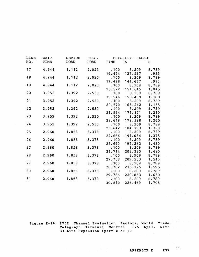
LINE WAIT DEVICE PREY. PRIORITY - LOAD NO. TIME LOAD LOAD TIME A B
17 4.944 1 • 1 1 2 2.023 .100 8.209 8.789 16.474 137.597 .935
18 4.944 1 • 112 2.023 .100 8.209 8.789 17.498 144.677 .990
19 4.944 1 • 11 2 2.023 .100 8.209 8.789 18.522 151.645 1.045
20 3.952 1.392 2.530 .100 8.209 8.789 19.546 158.499 1.100
21 3.952 1 .392 2.530 .100 8.209 8.789 20.570 165.242 1.155
22 3.952 1 .392 2.530 .100 8.209 8.789 21.594 171.871 1.210
23 3.952 1.392 2.530 .100 8.209 8.789 22.618 178.388 1.265
24 3.952 1.392 2.530 .100 8.209 8.789 23.642 184.793 1.320
25 2.960 1 .858 3.378 .100 8.209 8.789 24.666 191.084 1.375
26 2.960 1.858 3.378 ' .100 8.209 8.789 25.690 197.263 1.430
27 2.960 1.858 3.378 .100 8.209 8.789 26.714 203.330 1.485
28 2.960 1.858 3.378 .100 8.209 8.789 27.738 209.283 1.540
29 2.960 1.858 3.378 .100 8.209 8.789 28.762 215.125 1 • 595
30 2.960 1 .858 3.378 .100 8.209 8.789 29.786 220.853 1.650
31 2.960 1.858 3.378 .100 8.209 8.789 30.810 226.469 1.705
Figu~e E-2~: 2702 Channel Evaluation Facto~s, World T~ade Telegraph Terminal Control (75 bps), with 31-Line Expansion (part 2 of 2)
APPENDIX E E37

LINE WAIT DEVICE PREY. PRIORITY - LOAD NO. TIME LOAD LOAD TIME A B
1 71.984 .076 • 139 . 139 9.000 .073 2 35.984 . 153 .278 .100 7.418 17.578
.602 17.912 • 147 3 23.984 .229 .417 .100 7.418 17.578
1 • 114 26.755 .220 4 17.744 .310 .564 .100 7.418 17.578
1.626 35.523 .293 5 14.384 .382 .695 .100 7.418 17.578
2.138 44.216 .367 6 11.984 .459 .834 .100 7.418 17.578
2.650 52.834 .440 7 10.064 .547 .994 . 100 7.418 17.578
3.162 61 .377 .513 8 8.624 .638 1.160 .100 7.418 17.578
3.674 69.845 .587 9 7.664 .718 1.305 .100 7.418 17.578
4.186 78.237 .660 10 7.184 .766 1.392 .100 7.418 17.578
4.698 86.555 .733 1 1 6.224 .884 1.607 .100 7.418 17.578
5.210 94.797 .807 12 5.744 .958 1.741 .100 7.418 17.578
5.722 102.965 .880 13 5.264 1 .045 1.900 .100 7.418 17.578
6.234 111.057 .953 14 4.784 1.150 2.090 .100 7.418 17.578
6.746 119.074 1.027 15 4.784 1 . 150 2.090 .100 7.418 17.578
7.258 127.016 1.100
Figu~e E-25: 2702 Channel Evaluation Facto~s, Wo~ld Trade Telegraph Terminal Control (100 bps), without 31-Line Expansion
E38 IBM 4331 Processo~ Channel Cha~acte~istics

LINE WAIT DEVICE PREV. PRIORITY - LOAD NO. TIME LOAD LOAD TIME A B
1 2
3
4
5
6
7
8
9
10
1 1
12
13
14
15
16
71.408 .077 . 140 .100 9.000 .073 35.696 • 154 .280 .100 8.209 8.789
1 • 11 4 17.837 • 147 23.792 .231 .420 .100 8.209 8.789
2.138 26.530 .220 17.840 .308 .561 .100 8.209 8.789
3.162 35.072 .293 13.872 .396 .721 .100 8.209 8.789
4.186 43.465 .367 11.888 .463 .841 .100 8.209 8.789
5.210 51.708 .440 9.904 .555 1 .010 • 100 . 8.209 8.789
6.234 59.800 .513 8.912 .617 1 .122 .100 8.209 8.789
7.258 67.742 .587 7.920 .694 1 .263 .100 8.209 8.789
8.282 75.534 .660 6.928 .794 1 .443 .100 8.209 8.789
9.306 83.176 .733 5.936 .927 1 .685 .100 8.209 8.789
10.330 90.667 .807 5.936 .927 1 .685 .100 8.209 8.789
11.354 98.008 .880 4.944 1 • 1 1 2 2.023 . 100 8.209 8.789
12.378 105.200 1.953 4.944 1 . 1 1 2 2.023 .100 8.209 8.789
13.402 112.241 1.027 3.952 1.392 2.530 .100 8.209 8.789
14.426 119.131 1 .100 3.952 1.392 2.530 .100 8.209 8.789
15.450 125.872 1.173
Figure E-26: 2702 Channel Evaluation Factors, World Trade Telegraph Terminal Control (100 bps), with 31-Line Expansion (part 1 of 2)
APPENDIX E E39
.Ji

LINE WAIT DEVICE PRE V • PRIORITY - LOAD NO. TIME LOAD LOAD TIME A B
17 3.952 1.392 2.530 .100 8.209 8.789 16.474 132.462 1.247
18 3.952 1.392 2.530 .100 8.209 8.789 17.498 138.903 1 .320
19 2.960 1.858 3.378 .100 8.209 8.789 18.522 145.193 1 • 393
20 2.960 1.858 3.378 .100 8.209 8.789 19.546 151.333 1.467
21 2.960 1.858 3.378 .100 8.209 8.789 20.570 157.322 1 • 540
22 2.960 1.858 3.378 .100 8.209 8.789 21.594 163.162 1.613
23 2.960 1.858 1
3.378 .100 8.209 8.789 22.618 168.851 1.687
24 2.960 1.858 3.378 .100 8.209 8.789 23.642 174.390 1.760
25 1.968 2.795 5.081 .100 8.209 8.789 24.666 179.779 1 • 833
26 1 .968 2.795 5.081 .100 8.209 8.789 25.690 185.018 1.907
27 1 .968 .2. 795 5.081 • 100 8.209 8.789 26.714 190.106 1.980
28 1 .968 2.795 5.081 .100 8.209 8.789 47.738 195.045 2.053
29 1 .968 2.795 5.081 .100 8.209 8.789 28.762 199.833 2.127
30 1.968 2.795 5.081 • 1 00 8.209 8.789 29.786 204.471 2.200
31 1 .968 2.795 5.081 · 100 8.209 8.789 30.810 208.959 2.273
Figure E-26: 2702 Channel Evaluation Factors, World Trade Telegraph Terminal Control (100 bps), with 31-Line Expansion (part 2 of 2)
E40 IBM 4331 Proces,sor Cnannel Characteristics

System Identification
Date . . . . . . . . . . .........
Priority Load
Priority Devices Time A B
Block MPX Channel ....... -. Device No ...••...•.•••..
Nanle ••••.••••••..•••••.
DASD Adapter - -Device No ••••••...•.•.•• Name •.••.•..••...•.••.•
Byte MPX Channel - -Device No •..••••••.••••.
Nanle ..•.•..••••••.•••..
Magnetic Tape Adapter .,...... -Device No ••••.•••••..•..
Name .•.••••••...•...••.
().In 8.Z'" 6.'18'1 1 1'1-./1/ S'.III S.17' 2.7~ZS$ "1."'1 /'1$1
2
3
Devices at Prority Positions on 4
Byte Multiplexer Channel
........ :- -- -
IBM 4331
Waiting Devices (Priority po
1 1
Device No. 2."l() z,. Devi
Name . . . . . . . . . . . Nam
Wait Wait Time . 3. .. 9.$~ Tim,1
A
----
(A Sum)
ASum7 Wait Time
Device Load
Previous Load·
LOAD SUM.,.
I R I
These entries relate
the following chara to a 2702 having
cteristics; IBM Terminal Con tro] Type I
bits/second Line Speed=134.5
Au topolling
Thirty-one line m aximum capacity 14 lines attached
I (8 Sum)
= ......
= 3.~?" (A
=2..S~' A SL Wait
Devi, I = ....... Loac
Prev Loa~
LOA surv
I000.-o
--.J
Figu~e E-27: Example of load sum wo~ksheet ent~ies fo~ a 2702 (with all communication lines of the same type)
APPENDIX E E41

This page has been left blank intentionally
E42 IBM 4331 P~ocesso~ Channel Cha~acte~istics

APPENDIX L. IBM 2703 TRANSMISSION CONTROL: PRIORITY ASSIGNMENT AND CHANNEL EVALUATION FACTORS
This appendix describes:
1. How to assign the priority of a 2703 T~ansmission Control in ~elation to other devices on the byte-multiplexer channel, for use in step 1 of Figure 2.11 when testing byte-multiplexer channel data overrun.
2. How to obtain the following channel evaluation factors of a 2703 for use in steps 2 and/or 3 of Figure 2.11.
Wait time Device load Previous load
For configurations having byte-multiplexer channel, representative.
more than consult
How to Assign Priority Position of a 2703
one your
2703 on local
the IBM
Assign to the 2703 the lowest priority of the class-1 devices, regardless of relative wait times.
How to Calculate Channel Evaluation Factors for a 2703
The procedure for calculating the channel evaluation factors has two stages:
1. To determine the "critical" base.
2. To obtain the required channel evaluation factors from simple formulas by using factors that are associated with the critical base.
How to Determine the "Critical" Base
For the purpose of this A, B, and C. Using the F-1, proceed by:
procedure, call the installed bases calculation format shown in Figure
1. Enter the number of lines NCA), NCB), NCC) to be installed on each base. If less than three bases are used, enter the number of lines for the unused base as 0 (zero).
2. From Figure F-2, enter the internal priority number PCA), PCB), P(C) for each base according to the base type and the number of lines installed. For any base that is not used, enter the priority number as 0 (zero).
APPENDIX F F1
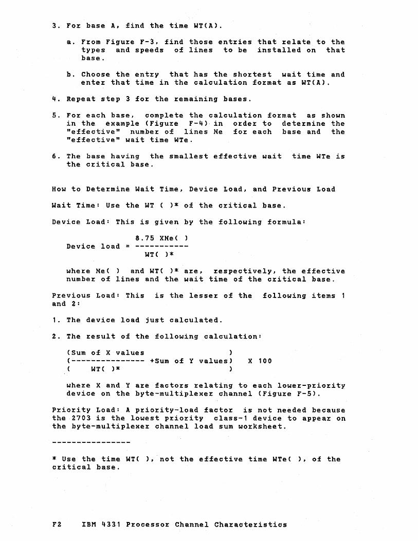
3. Fo~ base A, find the time WT(A).
a. F~om Figu~e F-3, find those ent~ies that ~elate to the types and speeds of lines to be installed on that base.
b. Choose the ent~y that has the sho~test wait time and ente~ that time in the calculation fo~mat as WT(A).
4. Repeat step 3 fo~ the ~emaining bases.
5. Fo~ each base, complete the calculation fo~mat as shown in the example (Figu:z:e F-4)· in o:z:de~ to dete~mine the "effective" numbe~ of lines He fo~ each base and the "effective" wait time WTe.
6. The base having the smallest effective wait time WTe is the c~itical base.
How to Dete~mine Wait Time, Device Load, and P~evious Load
Wait Time: Use the WT ( )* of the c:z:itical base.
Device Load: This is given by the following fo~mula:
8.75 XHe ( ) Device load = ----------
WT( ) * whe~e He( ) and WT( )* al:e, ~espectively, the effective numbe:z: of lines and the wait time of the c:z:itical base.
P~evious Load: This is the lesse~ of the following items and 2:
1. The device load just calculated.
2. The ~esult of the following calculation:
(Sum of X values ) (--------------- +Sum of Y values) C WTC)* )
X 100
whe~e X and Y a~e facto~s ~elating to each lowe~-p~io~ity device on the byte-multiplexe:z: channel (Figu:z:e F-5).
Pl:io~ity Load: A p~io:z:~ty-load facto:z: is not needed because the 2703 is the lowest p:z:io:z:ity class-1 device to appea:z: on the byte-multiplexe:z: channel load sum wo:z:ksheet.
* Use the time WT( ), not the effective time WTe( ), of the c~itical base.
F2 IBM 4331 P:z:ocesso:z: Channel Cha~acte~istics
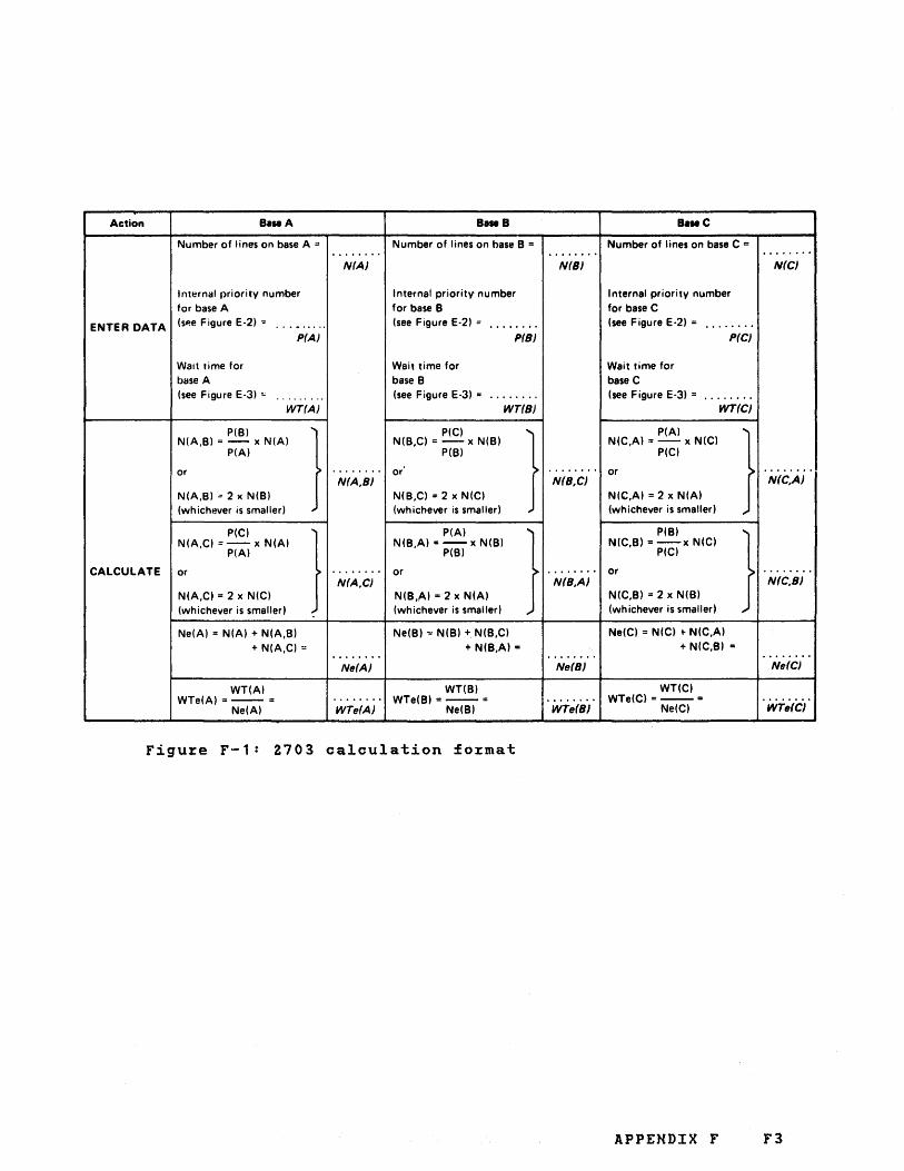
Action B.seA B.seB B.seC
Number of lines on base A '" Number' of lines on base B ::: Number of lines on base C = ....... . . ....... ... , .... N(A} N(B} N(C}
Internal priority number Internal priority number Internal priority number for base A for base B for base C
ENTER DATA (sp.e Figure E-2) ." ......... (see Figure E-2) :: . ....... (see Figure E-2) = . ....... P(A} P(B) P(C} .
Walt time for Wait time for Wait time for base A base B base C (see Figure E-3) '" .. ....... (see Figure E-3) = ........ (see Figure E-3) = . .......
WT(A} WT(B) WT(C}
P(B)
} PIC)
} PIA)
} N(A,B) = - x N(A) N(B,C) = - x N(B) N(C,A) = - x N(C)
PIA) P(B) PIC)
or ....... . or ........ or . ....... N(A,B} N(B,C) N(C,A)
N(A,B) .: 2 x N(B) N(B,C) = 2 x N(C) N(C,A) ::: 2 x N(A) (whichever is smaller) (whichever is smaller) (whichever is smallerl
PIC)
} PIA)
} P(B)
} N(A,C) = - x N(A) N(B,A) = - x N(B) N(C,B) = -x N(C) PIA) P(B) PIC)
CALCULATE or ....... . or ........ or . ....... N(A,C} N(B,A) N(C,B)
N(A,C) = 2 x N(C) N(B,A) = 2 x N(A) N(C,B) = 2 x N(B)
(whichever is smallerl (whichever is smaller) (whichever is smallerl
Ne(A) = N(A) + N(A,BI Ne(B) '" N(B) + N(B,C) Ne(C) = N(C) ~ N(C,A)
+ N(A,C)::: + N(B,A) = + N(C,BI = ....... . . ....... ........ Ne(A} Ne(B) Ne(C}
WT(A) WT(B) WT(C) WTe(A) ::-- = ........ WTe(BI =--= . ....... WTe(C) =--= . .......
Ne(A) WTe(A} Ne(BI WTe(B) Ne(CI WTe(C}
Figure F-1: Z703 calculation format
APPENDIX F F3

Type of be. 1 N be f r 11 nternel priority um r 0 In" number
Start-Stop Base Type I 16 1 32 2 48 3 64 4 80 5 88 6
Start-Stop Base Type II 8 1 16 3 24 4
Synchronous Base 4 1 Type 1A 8 3
12 4 16 5 20 7 24 8
Synchronous Base 4 2 Type 1B 8 4
12 6 16 8
Synchronous Base 4 3 Type 2A 8 5
12 8
Figu~e F-2: Inte~nal p~io~ity numbe~s as functions of 2703 base types and numbe~ of lines installed pe~ base
F4 IBM 4331 P~ocesso~ Channel Cha~acte~istics
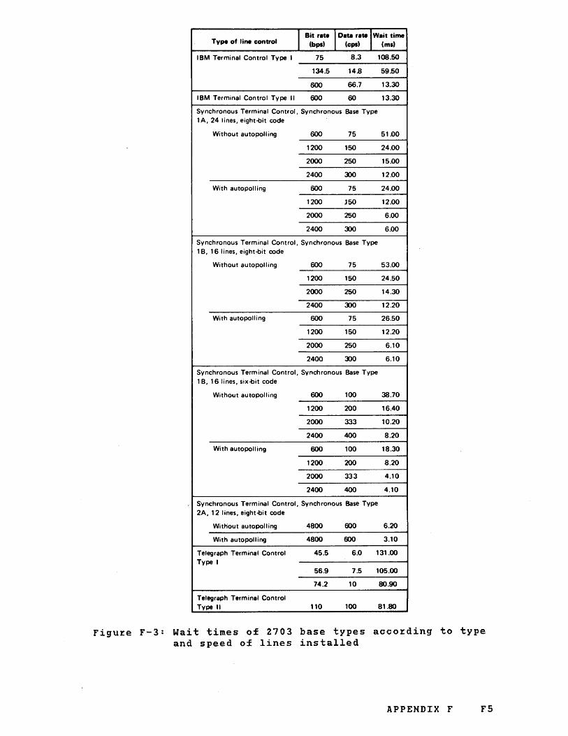
Type of line control J Bit rate I Data rate I Wait time
(bpst (cpst (mit
I BM Terminal Control Type I 75 8.3 108.50
134.5 14.8 59.50
600 66.7 13.30
IBM Terminal Control Type II 600 60 13.30
Synchronous Terminal Control, Synchronous Base Type lA, 24 lines, eight-bit code
Without autopolling 600 75 51.00
1200 1-50 24.00
2000 250 15.00
2400 ~O 12.00
With autopolling 600 75 24.00
1200 150 12.00
2000 250 6.00
2400 ~o 6.00
Synchronous Terminal Control, Synchronous Base Type 1 B, 16 lines, eight-bit code
Without autopolling 600 75 53.00
1200 150 24.50
2000 250 14.30
2400 ~ 12.20
With autopolling 600 75 26.50
1200 150 12.20
2000 250 6.10
2400 ~O 6.10
Synchronous Terminal Control, Synchronous Base Type 1 B, 16 lines, six-bit code
Without autopolling 600 100 38.70
1200 200 16.40
2000 333 10.20
2400 400 8.20
With autopolling 600 100 18.30
1200 200 8.20
2000 333 4.10
2400 400 4.10
Synchronous Terminal Control, Synchronous Base Type 2A, 12 lines, eight-bit code
Without autopolling 4800 600 6.20
With autopolling 4800 600 3.10
Telegraph Terminal Control 45.5 6.0 131.00 Type I
56.9 7.5 105.00
74.2 10 80.90
Telegraph Terminal Control Type II 110 100 81.80
Figu~e F-3: Wait times of 2703 base types acco~ding to type and speed of lines installed
APPENDIX F F5

These entries relate to a 2703 having the following bases and lines: Base A: Start·Stop Base Type I, with 88 lines, having IBM Terminal Control Type I
and working at 134.5 bits per second. Base B: Start·Stop Base Type II, with 24 lines, having IBM Terminal Control Type II
and working at 600 bits per second. Base C: Synchronous Base Type lA, with 24 lines, having synchronous terminal
control, autopolling, and working at 2400 bits per second.
The example shows WTe(C) to be the smallest effective wait time (0.111) and, hence, base C to be the critical base.
Action B.seA B •• B
Number of lines on base A =
"~".'" Number of lines on base B ..
N(AJ
Internal priority number Internal priority number for base A
... l? .. for base B
ENTER DATA (see Figure E·2) = (see Figure E·2) • ..+ .. PtA) P(BJ
Wait time for Wait time for base A base B (see Figure E·3) = $~ .. ~.Q.. (see Figure E·3) III I.~. :~q
WT(A) WT(B)
PIB)
} PIC)
} N(A,B) = - x N(A) N(B,C) .. - x N(B)
PIA) .. +.~. P(B)
or or N(A,B)
N(A,B) = 2 x N(B) N(B,C) .. 2 x N(C) (whichever is smaller) (whichever is smaller)
, PIC)
} PIA)
} N(A,C) = --xN(A) N(B,A) :.--x N(B)
PIA) 4.e ..
P(B)
CALCULATE or or N(A,C)
N(A,C) = 2 x N(C) N(B,A) = 2'x N(A) (whichever is smaller) (whichever is smaller)
Ne(A) = N(A) + N(A,B) Ne(B) '" N(B) + N(B,C) + N(A,C) = . !~~ .. + N(B,A) •
Ne(A)
WT(A) WTe(A) =-_ .. 9-.~~~ . WT(B)
WTe(B) .. -'-- • Ne(A) WTe(A) , Ne(B)
B •• C
.. ~.~ .... Number of lines on base C = N(B)
Internal priority number for base C lsee Figure E·2) .. ..$ ..
P(C)
Wait time for b.se C (see Figure E·3) .. .6:.QQ.
WT(C)
PIA)
} 'NfC,A) .. - x N(C)
.4.~ .. PIC)
or N(B,C)
N(C,A) • 2 x N(A) (whichever is smaller)
P(B)
} N(C,B) .. - x N(C)
PIC) 36 or
N(B,A) -N(C,B) .. 2 x N(B) (whichever is smalle~)
Ne(C) -= N(C) + N(C,A)
. (9.~. +N(C,B) ..
Ne(B)
q:.I~.~. WT(C) WTe(C)· ---
WTtI(B) Ne(C)
Figure F-4: Example calculations to determine critical
.. Z4 ... NrC)
..,~ ... N(C,A)
..I.~ ... N(C,B)
..~.4 .. Ne(C)
9'. H.I .. WTe(C)
base, effective number of lines, and 2703 wait ~ime \
F6 IBM 4331 Processor Channel Characteristics

Input/output device IOperating model
1017 Paper Tape Reader or 1-byte 1018 Paper Tape Punch
1403 Printer
1443 Printer
1-byte 4-byte
1-byte 2-byte 4-byte
2260 Display Station Read 1 byte Write 1 byte
2520 Card Punch Model B2 or B3
2540 Card Read Punch punching
2540 Card Read Punch reading
3211 Printer
3277-1 Display 3277-2 Display 3284-1 Printer 3286-1 Printer 3288-1 Printer 3284-2 Printer 3286-2 Printer 3288-2 Printer
EBCDIC 1-byte Col.bin. 2-byte
EBCDIC 1-byte 2-byte
Col. bin. 1-byte 2-byte
EBCDIC 1-byte 2-byte
Col. bin. 1-pyte 2-byte
1-byte 6-byte
1-byte 1-byte 1-byte 1-byte 1-byte 1-byte l-byte 1-byte
3505 Card Reader EBCDIC l-byte Model B1 or B2 Card Im. 2-byte
3525 Card Punch Model P1 or P2
EBCDIC l-byte Card Im. 2-byte
3886 Optical Character Reader Model 1 or 2
3890 Document Processor
1-byte
4-byte
x y
o . 0.009
------- -------9.5 0 2.97 0
------- -------9.48 0 5.82 0 3.99 0
------- -------0 0.169 0 O. 176
------- -------5.84 0 5.84 0
------- -------6.56 0 3.25 0
12.64 0 6.56 0
------- -------5.52 0 3. 16 0
11 .04 0 6.32 0
------- -------8.84 0 1 .94 0
------- -------27.36 0
109.44 0 27.36 0 27.36 0 27.36 0
109.44 0 109.44 0 109.44 0
------- -------4.32 0 5.04 0
------- -------4.56 0 5.36 0
------- -------8. 10 0
------- -------28.8 0
------- --------
Figure F-5: X and Y values used to calculate previous load for 2703
APPENDIX F F7

This page has been left blank intentionally
F8 IBM 4331 Pzocessoz Channel Chazactezistics

IBM 4331 Processor Channel Characteristics GA33·1527·Q
Your views about this publication may help improve its usefulness; this form will be sent to the author's department for appropriate action. Using this form to request system assistance, or additional publications will delay response. For more direct handling of such requests, please contact your IBM representative or the IBA1 Branch Office serving your locality.
Possible topics for comment are:
Clarity Accuracy Completeness Organization Index Figures Examples Legibility
READER'S COMMENT FORM
What is your occupation? _________________________________________________ _
Number of latest Technical Newsletter (if any) concerning this publication:
Please indicate in the space below if you wish a reply.
Thank you for your cooperation. No postage stamp necessary if mailed in the U.S.A. (Elsewhere, an IBM office or representative will be happy to forward your comments),

GA33·1527·0
Your comments, please •..
This manual is part of a library that serves as a reference source for systems analysts, programmers, and operators of IBM systems. Your comments on the other side of this form will be carefully reviewed by the persons responsible for writing and publishing this material. All comments and suggestions become the property of IBM.
Fold and tape Please Do Not Staple Fold and tape ............................................................................................................................................. , .......................................... .
I II II I
Business Reply Mail No postage stamp necessary if mailed in the U.S.A.
Postage will be paid by:
I nternational Business Machines Corporation Department 8138
1133 Westchester Avenue White Plains, New York 10604
First Class Permit 40 Armonk New York
......................... , ... "F~ld '~~'d 't~i;e" ....................... 'pi~~~ 'D~ 'N~t'St~~i~"'" ................................................. "i='~id' ~~d'~~~~""""""
lldIDOO ~
International Buslneas Machines Corporation Data ProceSSing Division 1133 Westchester Avenue, White Plains, New York 10604 (U.S.A. only)
IBM World Trade Corporation 821 United Nations Plaza, New York 10017 (International)
(')
S


GA33·1527·Q
International Bu.-iness Machines Corporation Data Processing Division 1133 Westchester Avenue, White Plains, New York 10604 (U.S.A. only)
IBM World Trade Corporation 821 United Nations Plaza, New York 10017 (International)