ibm hardware management console for pseries installation...
TRANSCRIPT

IBM Hardware Management Console forpSeries Installation and Operations Guide
SA38-0590-02


IBM Hardware Management Console forpSeries Installation and Operations Guide
SA38-0590-02

Third Edition (October 2002)
Before using this information and the product it supports, read the information in Appendix A, “Notices” on page 161and product warranties included with your system.
A reader’s comment form is provided at the back of this publication. If the form has been removed, address commentsto Publications Department, Internal Zip 905-6C006, 11400 Burnet Road, Austin, Texas 78758-3493. To sendcomments electronically, use this commercial internet address: [email protected]. Any information that yousupply may be used without incurring any obligation to you.
© International Business Machines Corporation 2001, 2002. All rights reserved. Note to U.S. Government Users -Documentation related to restricted rights - Use, duplication, or disclosure is subject to the restrictions set forth in theGSA ADP Schedule Contract with IBM Corp.
Contents
Safety Notices . . . . . . . . . . . . . . . . . . . . . . . . ixLaser Safety Information . . . . . . . . . . . . . . . . . . . . . x
Laser Compliance . . . . . . . . . . . . . . . . . . . . . . x
About This Book . . . . . . . . . . . . . . . . . . . . . . . xiISO 9000 . . . . . . . . . . . . . . . . . . . . . . . . . . xiOnline Publications. . . . . . . . . . . . . . . . . . . . . . . xiHighlighting . . . . . . . . . . . . . . . . . . . . . . . . . xiRelated Publications . . . . . . . . . . . . . . . . . . . . . . xiTrademarks . . . . . . . . . . . . . . . . . . . . . . . . . xii
Chapter 1. Reference Materials . . . . . . . . . . . . . . . . . . 1Documentation Overview . . . . . . . . . . . . . . . . . . . . . 2
Chapter 2. Introducing the Hardware Management Console . . . . . . . . 5Managed System Operations . . . . . . . . . . . . . . . . . . . 5
Partitioning . . . . . . . . . . . . . . . . . . . . . . . . 5Service Focal Point . . . . . . . . . . . . . . . . . . . . . . . 6
Chapter 3. Installing and Configuring the HMC . . . . . . . . . . . . . 7Installing the Hardware Management Console . . . . . . . . . . . . . . 7
Position the HMC and Monitor . . . . . . . . . . . . . . . . . . 7Connect the Cables . . . . . . . . . . . . . . . . . . . . . 7Connect the 8-Port Adapter Cables . . . . . . . . . . . . . . . . 10Connect the External Modem . . . . . . . . . . . . . . . . . . 10Connect the LAN Cable . . . . . . . . . . . . . . . . . . . . 11Plug in the HMC Power Cords. . . . . . . . . . . . . . . . . . 11
Getting Started . . . . . . . . . . . . . . . . . . . . . . . . 12Change the Keyboard Settings . . . . . . . . . . . . . . . . . 12Log in to the HMC. . . . . . . . . . . . . . . . . . . . . . 12Change the Predefined hscroot Password . . . . . . . . . . . . . . 12Change the Predefined Root-User Password on the HMC . . . . . . . . 12Check Your HMC Software Version . . . . . . . . . . . . . . . . 13Create Users . . . . . . . . . . . . . . . . . . . . . . . 13
Installing the HMC Interface after Replacing the Hard Drive . . . . . . . . . 13Upgrading the HMC Software . . . . . . . . . . . . . . . . . . . 14
Prepare for the Upgrade . . . . . . . . . . . . . . . . . . . 14Upgrade the HMC Software . . . . . . . . . . . . . . . . . . 16
Setting Up Your HMC Software for Service . . . . . . . . . . . . . . 17Setting Up Service Authority . . . . . . . . . . . . . . . . . . . 17
Chapter 4. Partitioning . . . . . . . . . . . . . . . . . . . . . 19Types of Partitions . . . . . . . . . . . . . . . . . . . . . . 19
Logical Partitions . . . . . . . . . . . . . . . . . . . . . . 19Full System Partition . . . . . . . . . . . . . . . . . . . . . 19
Benefits of Partitioning . . . . . . . . . . . . . . . . . . . . . 19Managing a Partitioned System . . . . . . . . . . . . . . . . . . 20
iii
Managed Systems . . . . . . . . . . . . . . . . . . . . . 20Partitions. . . . . . . . . . . . . . . . . . . . . . . . . 20Profiles . . . . . . . . . . . . . . . . . . . . . . . . . 21
Chapter 5. Preparing for Partitioning . . . . . . . . . . . . . . . . 23Partitioning Requirements . . . . . . . . . . . . . . . . . . . . 23
Overall Requirements . . . . . . . . . . . . . . . . . . . . 23Assignable Resources for Logical Partitioning . . . . . . . . . . . . 23Assignable Resources for Affinity Partitioning . . . . . . . . . . . . . 26
Assigning a Host Name to Your Partition . . . . . . . . . . . . . . . 27Operating States . . . . . . . . . . . . . . . . . . . . . . . 27
Operating States for Managed Systems . . . . . . . . . . . . . . 27Operating States for Partitions. . . . . . . . . . . . . . . . . . 28
Chapter 6. User Environment . . . . . . . . . . . . . . . . . . 29Using the Login Window . . . . . . . . . . . . . . . . . . . . 29Shutting Down, Rebooting and Logging Out of the HMC . . . . . . . . . . 29HMC System Management Environment . . . . . . . . . . . . . . . 30
Using Multiple HMCs . . . . . . . . . . . . . . . . . . . . . 30Using Multiple Managed Systems Connected to One HMC . . . . . . . . 31
HMC Application Overview . . . . . . . . . . . . . . . . . . . . 31System Manager Security . . . . . . . . . . . . . . . . . . . 31Server and Partition Application Group . . . . . . . . . . . . . . . 31Software Maintenance Application Group . . . . . . . . . . . . . . 32HMC Management Application Group . . . . . . . . . . . . . . . 32HMC Maintenance Application Group . . . . . . . . . . . . . . . 32Service Applications Group . . . . . . . . . . . . . . . . . . . 33
HMC Management Window . . . . . . . . . . . . . . . . . . . 34Console Menu . . . . . . . . . . . . . . . . . . . . . . . 34Object Menu . . . . . . . . . . . . . . . . . . . . . . . 35Selected Menu . . . . . . . . . . . . . . . . . . . . . . . 35View Menu . . . . . . . . . . . . . . . . . . . . . . . . 35Window Menu . . . . . . . . . . . . . . . . . . . . . . . 35Help Menu . . . . . . . . . . . . . . . . . . . . . . . . 35
The Documentation Browser . . . . . . . . . . . . . . . . . . . 35HMC Keyboard Control . . . . . . . . . . . . . . . . . . . . . 35
Using Mnemonics and Shortcuts . . . . . . . . . . . . . . . . . 35Navigating the Console with the Keyboard. . . . . . . . . . . . . . 36Navigating Window Fields with the Keyboard . . . . . . . . . . . . . 36Accessing Help with the Keyboard . . . . . . . . . . . . . . . . 37
Chapter 7. System Configuration . . . . . . . . . . . . . . . . . 39Setting and Viewing the Console Date and Time. . . . . . . . . . . . . 39Viewing Console Events. . . . . . . . . . . . . . . . . . . . . 40Customizing Network Settings . . . . . . . . . . . . . . . . . . . 40
Using Network Adapters to Communicate with Partitions . . . . . . . . . 41Setting the IP Address . . . . . . . . . . . . . . . . . . . . 42Setting Domain Names . . . . . . . . . . . . . . . . . . . . 42Setting Host Names . . . . . . . . . . . . . . . . . . . . . 43Adding and Changing IP Addresses and Host Names . . . . . . . . . . 43
iv IBM Hardware Management Console for pSeries Installation and Operations Guide
Setting Routing Information. . . . . . . . . . . . . . . . . . . 44Setting Device Attributes . . . . . . . . . . . . . . . . . . . 44
Testing Network Connectivity . . . . . . . . . . . . . . . . . . . 45Scheduling Backups . . . . . . . . . . . . . . . . . . . . . . 45
Scheduling a Backup Operation . . . . . . . . . . . . . . . . . 46Reviewing an Existing Scheduled Operation . . . . . . . . . . . . . 46
Enabling and Disabling Remote Commands . . . . . . . . . . . . . . 47Configuring a Serial Adapter . . . . . . . . . . . . . . . . . . . 48
Configuring Serial Adapters . . . . . . . . . . . . . . . . . . 48Configuring RS422 Ports on an 8–Port Adapter . . . . . . . . . . . . 50
Enabling Remote Virtual Terminal Connections . . . . . . . . . . . . . 50Changing the HMC Interface Language . . . . . . . . . . . . . . . 50
Chapter 8. Installing and Using the Remote Client . . . . . . . . . . . 53Installation Requirements to Support Remote Client and Remote Client Security 53Installing the Remote Client on a Microsoft Windows System . . . . . . . . 53Uninstalling the Remote Client from a Microsoft Windows System . . . . . . . 54Installing the Remote Client on a Linux System . . . . . . . . . . . . . 54Uninstalling Remote Client from a Linux System. . . . . . . . . . . . . 55Installing the Remote Client Security . . . . . . . . . . . . . . . . 55
Installing Remote Client Security on the Microsoft Windows System . . . . . 55Uninstalling Remote Client Security from a Microsoft Windows System . . . . 56Installing the Remote Client Security on a Linux System . . . . . . . . . 56Uninstalling Remote Client Security from a Linux System . . . . . . . . . 57Configuring Remote Client Security . . . . . . . . . . . . . . . . 57
Chapter 9. System Manager Security . . . . . . . . . . . . . . . . 59Configuring HMC System Manager Servers and Clients for Secure Operation . . . 59
Configure One HMC as a Certificate Authority . . . . . . . . . . . . 59Generate Private Key Ring Files for the HMCs That You Want to Manage
Remotely . . . . . . . . . . . . . . . . . . . . . . . . 60Install the Private Key Ring Files and Configure Your HMC Servers as Secure
System Manager Servers . . . . . . . . . . . . . . . . . . 60Distribute the Certificate Authority’s Public Key to Your Clients . . . . . . . 62
Viewing Configuration Properties . . . . . . . . . . . . . . . . . . 63Configure HMC Object Manager Security . . . . . . . . . . . . . . . 64
Chapter 10. Inventory Scout Services . . . . . . . . . . . . . . . 65Configuring the Inventory Scout Services Profile . . . . . . . . . . . . . 65
Manually Configuring Inventory Scout Services . . . . . . . . . . . . 66Conducting Microcode Surveys . . . . . . . . . . . . . . . . . . 67Collecting Vital Product Data Information . . . . . . . . . . . . . . . 67Restarting Inventory Scout Services . . . . . . . . . . . . . . . . . 68
Chapter 11. Using Two HMCs Connected to One Managed System . . . . . 69Working with Two HMCs . . . . . . . . . . . . . . . . . . . . 69Other Considerations for Redundant HMCs . . . . . . . . . . . . . . 70
Chapter 12. User Management . . . . . . . . . . . . . . . . . . 71Overview of Roles. . . . . . . . . . . . . . . . . . . . . . . 71
Contents v
Roles and Tasks . . . . . . . . . . . . . . . . . . . . . . . 72User Management Tasks . . . . . . . . . . . . . . . . . . . 77
Chapter 13. Basic System Management Tasks . . . . . . . . . . . . 81Managing the System . . . . . . . . . . . . . . . . . . . . . 81Powering On the Managed System . . . . . . . . . . . . . . . . . 82
Partition Standby . . . . . . . . . . . . . . . . . . . . . . 82Full System Partition . . . . . . . . . . . . . . . . . . . . . 82System Profiles . . . . . . . . . . . . . . . . . . . . . . 84
Powering Off the Managed System . . . . . . . . . . . . . . . . . 84Viewing Managed System Properties . . . . . . . . . . . . . . . . 84Managing Profile Data . . . . . . . . . . . . . . . . . . . . . 85
Backing Up Profile Data . . . . . . . . . . . . . . . . . . . . 85Restoring Profile Data . . . . . . . . . . . . . . . . . . . . 85Initializing Profile Data . . . . . . . . . . . . . . . . . . . . 86Removing Profile Data . . . . . . . . . . . . . . . . . . . . 86
Deleting the Managed System from the Contents Area . . . . . . . . . . 87Rebuilding the Managed System . . . . . . . . . . . . . . . . . . 87Releasing an HMC Lock on the Managed System . . . . . . . . . . . . 88Resetting the Operating System on a Partition . . . . . . . . . . . . . 89Managing a Frame of Managed Systems and Resources Connected to the HMC 89
Initializing a Frame’s Managed Systems and Resources . . . . . . . . . 90Viewing Frame Properties . . . . . . . . . . . . . . . . . . . 90Deactivating a Managed System’s Service Processor . . . . . . . . . . 91Resetting a Managed System’s Service Processor . . . . . . . . . . . 91Deactivating a Frame’s I/O Drawers . . . . . . . . . . . . . . . . 92
Chapter 14. Using Capacity Upgrade on Demand . . . . . . . . . . . 93Activating Process for Capacity Upgrade on Demand . . . . . . . . . . . 93Accepting the License Agreement . . . . . . . . . . . . . . . . . 95Displaying Capacity Upgrade on Demand Resources . . . . . . . . . . . 95
Viewing and Saving Capacity Upgrade on Demand Processor Order Information 96Activating Capacity Upgrade on Demand Resources . . . . . . . . . . . 96
Chapter 15. Server Management Tasks . . . . . . . . . . . . . . . 99Creating Partitions . . . . . . . . . . . . . . . . . . . . . . 99
Preparing Your System for Partitioning . . . . . . . . . . . . . . . 99Creating Logical Partitions . . . . . . . . . . . . . . . . . . . 99Creating Affinity Partitions . . . . . . . . . . . . . . . . . . . 102Activating Partitions . . . . . . . . . . . . . . . . . . . . . 104Reassigning Partition Resources Dynamically . . . . . . . . . . . . 105Deleting Partitions . . . . . . . . . . . . . . . . . . . . . 119Restarting the Operating System . . . . . . . . . . . . . . . . 120
Managing Partition Profiles . . . . . . . . . . . . . . . . . . . 120Creating Additional Partition Profiles . . . . . . . . . . . . . . . 121Viewing Partition Profile Properties . . . . . . . . . . . . . . . . 121Setting Service Authority . . . . . . . . . . . . . . . . . . . 121Copying Partition Profiles . . . . . . . . . . . . . . . . . . . 122Changing Default Partition Profiles . . . . . . . . . . . . . . . . 122Understanding Partition Boot Errors . . . . . . . . . . . . . . . 122
vi IBM Hardware Management Console for pSeries Installation and Operations Guide
Deleting Partition Profiles . . . . . . . . . . . . . . . . . . . 123Managing System Profiles . . . . . . . . . . . . . . . . . . . 123
Creating System Profiles . . . . . . . . . . . . . . . . . . . 123Viewing System Profile Properties . . . . . . . . . . . . . . . . 124Modifying System Profile Properties . . . . . . . . . . . . . . . 124Copying System Profiles . . . . . . . . . . . . . . . . . . . 124Deleting System Profiles . . . . . . . . . . . . . . . . . . . 124Activating System Profiles. . . . . . . . . . . . . . . . . . . 125Validating That System Profiles Will Activate Successfully . . . . . . . . 125Activating System Profiles When Other Partition Profiles Are Running . . . . 125Powering On Using a System Profile . . . . . . . . . . . . . . . 125
Chapter 16. Virtual Terminal Window . . . . . . . . . . . . . . . 127Virtual Terminal Windows on a Full System Partition . . . . . . . . . . . 128Opening a Virtual Terminal Window . . . . . . . . . . . . . . . . 128Opening Virtual Terminal Windows on a Partition . . . . . . . . . . . . 128Managing AIX Device Drivers on Partitions . . . . . . . . . . . . . . 129Installing AIX on a Full System Partition . . . . . . . . . . . . . . . 129Installing AIX on a Partition . . . . . . . . . . . . . . . . . . . 130Copying and Pasting Within a Virtual Terminal . . . . . . . . . . . . . 130Closing a Virtual Terminal Window . . . . . . . . . . . . . . . . . 131
Chapter 17. Software Maintenance for the HMC and the Frame . . . . . . 133Backing up Critical Console Data . . . . . . . . . . . . . . . . . 133Saving Upgrade Data . . . . . . . . . . . . . . . . . . . . . 134Installing Corrective Service for the HMC. . . . . . . . . . . . . . . 134Formatting Removable Media . . . . . . . . . . . . . . . . . . 135Receiving Corrective Service for the Frame . . . . . . . . . . . . . . 135Installing Corrective Service on the Frame . . . . . . . . . . . . . . 136
Chapter 18. Service Agent . . . . . . . . . . . . . . . . . . . 137Overview of Service Agent . . . . . . . . . . . . . . . . . . . 137Activating Service Agent . . . . . . . . . . . . . . . . . . . . 138
Obtaining Service Agent . . . . . . . . . . . . . . . . . . . 138Activating Service Agent the First Time . . . . . . . . . . . . . . 138
Configuring and Using Service Agent . . . . . . . . . . . . . . . . 139Registering and Customizing the Service Agent User Interface . . . . . . . 139Stopping the Service Agent User Interface . . . . . . . . . . . . . . 141Starting Service Agent Processes . . . . . . . . . . . . . . . . . 141Changing the Service Agent Mode . . . . . . . . . . . . . . . . . 141Stopping Service Agent Processes . . . . . . . . . . . . . . . . . 142Service Agent Status Indicators . . . . . . . . . . . . . . . . . . 142
Chapter 19. Service Focal Point . . . . . . . . . . . . . . . . . 145Getting Started . . . . . . . . . . . . . . . . . . . . . . . 145Testing Error Reporting. . . . . . . . . . . . . . . . . . . . . 145Service Focal Point Settings . . . . . . . . . . . . . . . . . . . 146
Automatic Call-Home Feature . . . . . . . . . . . . . . . . . 146Setting Up Surveillance . . . . . . . . . . . . . . . . . . . 146Enabling Surveillance Notifications . . . . . . . . . . . . . . . . 147
Contents vii
Working With Serviceable Events . . . . . . . . . . . . . . . . . 148Viewing Serviceable Events . . . . . . . . . . . . . . . . . . 148Viewing Serviceable Event Details . . . . . . . . . . . . . . . . 148Saving and Managing Extended Error Data . . . . . . . . . . . . . 149Viewing and Adding Serviceable Event Comments . . . . . . . . . . 149Closing a Serviceable Event . . . . . . . . . . . . . . . . . . 150Updating Field Replaceable Unit (FRU) Information . . . . . . . . . . 150Replacing an Existing FRU . . . . . . . . . . . . . . . . . . 150Adding a New FRU . . . . . . . . . . . . . . . . . . . . . 151Viewing Serviceable Event Partition Information . . . . . . . . . . . 151
Hardware Service Functions . . . . . . . . . . . . . . . . . . . 151Activating and Deactivating FRU Identity LEDs . . . . . . . . . . . . 151
Chapter 20. Using the Command Line . . . . . . . . . . . . . . . 153Commands . . . . . . . . . . . . . . . . . . . . . . . . 153Examples of Command Line Scripts . . . . . . . . . . . . . . . . 158
Example 1 . . . . . . . . . . . . . . . . . . . . . . . . 158Example 2 . . . . . . . . . . . . . . . . . . . . . . . . 158
Setting up Secure Script Execution Between SSH Clients and the HMC . . . . 159Deleting the Key from the HMC . . . . . . . . . . . . . . . . . 160
Appendix A. Notices . . . . . . . . . . . . . . . . . . . . . 161
Appendix B. Using Scripts to Connect Remotely . . . . . . . . . . . 163
Appendix C. Error Messages and Recovery Information . . . . . . . . 165Virtual Terminal Errors . . . . . . . . . . . . . . . . . . . . . 226Operating States . . . . . . . . . . . . . . . . . . . . . . . 226
Managed System Operating States . . . . . . . . . . . . . . . 227Partition Operating States . . . . . . . . . . . . . . . . . . . 228
Restoring Partition Resources . . . . . . . . . . . . . . . . . . 229Restoring Processor Resources . . . . . . . . . . . . . . . . . 229Restoring Adapter Resources . . . . . . . . . . . . . . . . . 230Restoring Memory Resources . . . . . . . . . . . . . . . . . 231
Error Recovery Actions. . . . . . . . . . . . . . . . . . . . . 232Rebuild is Indicated for Managed System . . . . . . . . . . . . . 232Steps to Rebuild a Managed System . . . . . . . . . . . . . . . 232Steps for Rebooting the HMC . . . . . . . . . . . . . . . . . 233Performing a File System Check on HMC Reboot . . . . . . . . . . . 233
Changing a Partition Host Name Manually . . . . . . . . . . . . . . 233Managed System States for the HMC . . . . . . . . . . . . . . . . 234
No Connection State . . . . . . . . . . . . . . . . . . . . 234Incomplete State . . . . . . . . . . . . . . . . . . . . . . 234Recovery State . . . . . . . . . . . . . . . . . . . . . . 235Error State . . . . . . . . . . . . . . . . . . . . . . . . 235Open Firmware State . . . . . . . . . . . . . . . . . . . . 235
Boot Error Values . . . . . . . . . . . . . . . . . . . . . . 235Releasing an HMC Lock on the Managed System. . . . . . . . . . . . 237
Index . . . . . . . . . . . . . . . . . . . . . . . . . . 239
viii IBM Hardware Management Console for pSeries Installation and Operations Guide
Safety Notices
A caution notice indicates the presence of a hazard that has the potential of causingmoderate or minor personal injury. Caution notices appear on the following page:
v 7
v x
For a translation of the safety notices contained in this book, see the System UnitSafety Information, order number SA23-2652.
ix
Laser Safety Information
CAUTION:This product may contain a CD-ROM, DVD-ROM, or laser module on a PCI card,which are class 1 laser products.C30
Laser ComplianceAll lasers are certified in the U.S. to conform to the requirements of DHHS 21 CFRSubchapter J for class 1 laser products. Outside the U.S., they are certified to be incompliance with the IEC 825 (first edition 1984) as a class 1 laser product. Consult thelabel on each part for laser certification numbers and approval information.
CAUTION:All mentioned laser modules are designed so that there is never any humanaccess to laser radiation above a class 1 level during normal operation, usermaintenance, or prescribed service conditions. Data processing environmentscan contain equipment transmitting on system links with laser modules thatoperate at greater than class 1 power levels. For this reason, never look into theend of an optical fiber cable or open receptacle. Only trained service personnelshould perform the inspection or repair of optical fiber cable assemblies andreceptacles.C25, C26
x IBM Hardware Management Console for pSeries Installation and Operations Guide
About This Book
This book provides information to operators and system administrators about how toinstall and use an IBM Hardware Management Console for pSeries (HMC) to manage asystem. This book includes information about the HMC software. It also discusses theissues associated with the planning and implementing of partitioning.
ISO 9000ISO 9000 registered quality systems were used in the development and manufacturingof this product.
Online PublicationsIBM Eserver pSeries and AIX publications are available online. This documentation isavailable at the following Web address:http://publib16.boulder.ibm.com/pseries/en_US/infocenter/base.
HighlightingThe following highlighting conventions are used in this book:
Bold Identifies commands, subroutines, keywords, files, structures, directories, andother items whose names are predefined by the system. Also identifiesgraphical objects such as buttons, labels, and icons that the user selects.
Italics Identifies parameters whose actual names or values are to be supplied by theuser.
Monospace Identifies examples of specific data values, examples of text similar to whatyou might see displayed, examples of portions of program code similar towhat you might write as a programmer, messages from the system, orinformation you should actually type.
Related PublicationsThe following publications contain related information:
v The documentation shipped with your managed system contains detailed planning,installation, and option information.
v The managed system’s user’s guide, which contains user information for themanaged system connected to your HMC.
v The AIX 5L Version 5.2 AIX Installation in a Partitioned Environment guide, ordernumber SC23-4382, contains information about installing, managing, and maintainingthe AIX 5L operating system in a partitioned environment.
v The Site and Hardware Planning Information, order number SA38-0508, containsinformation to help you plan the installation of your machine.
xi
v The Eserver pSeries Electronic Service Agent for eServer pSeries User’s Guide,order number LCD4-1060, provides detailed information about the Service Agentapplication.
v The Hardware Management Console for pSeries Maintenance Guide, providesinformation about servicing your HMC, and includes diagnostic and error information.
v The PCI Adapter Placement Reference, order number SA38-0538, providesinformation about where to place an adapter in your managed system.
v The eServer pSeries Planning for Partitioned-System Operations Guide, ordernumber SA38-0626, describes planning considerations for Dynamic Reconfigurationand Capacity Upgrade on Demand on products that can be partitioned.
TrademarksThe following terms are trademarks of the International Business Machines Corporationin the United States, other countries, or both:
v AIX
v AIX 5L
v Eserver
v IBM
v pSeries
Java and all Java-based trademarks and logos are trademarks or registered trademarksof Sun Microsystems, Inc. in the United States, other countries, or both.
Microsoft, Windows NT, Windows 2000, and Windows XP are all registered trademarksof the Microsoft Corporation in the United States and other countries.
Other company, product, and service names may be trademarks or service marks ofothers.
xii IBM Hardware Management Console for pSeries Installation and Operations Guide
Chapter 1. Reference Materials
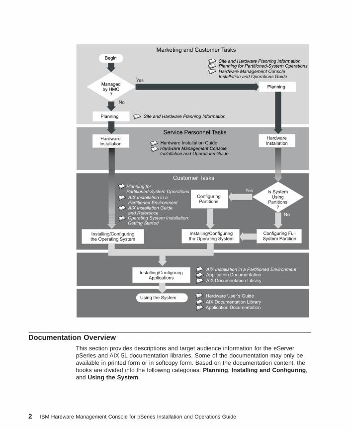
This chapter helps you get started with installing and configuring the Eserver pSeriesenvironment. The following information is included in the chapter:
v Eserver pSeries Roadmap
v Documentation Overview - Brief description of the printed and softcopydocumentation shipped including targeted audience
The Eserver pSeries Roadmap helps you locate marketing, service, and customertask information. The roadmap guides you through the tasks and the publications thatdocument those tasks.
1
Hardware Installation Guide
Hardware Management ConsoleInstallation and Operations Guide
AIX Installation in a Partitioned EnvironmentApplication Documentation
Application Documentation
AIX Documentation Library
AIX Documentation Library
Hardware User’s Guide
AIX Installation in aPartitioned EnvironmentAIX Installation Guideand ReferenceOperating System Installation:Getting Started
Installing/ConfiguringApplications
Installing/Configuringthe Operating System
Installing/Configuringthe Operating System
Configuring FullSystem Partition
Is SystemUsing
Partitions?
ConfiguringPartitions
Customer Tasks
Service Personnel Tasks
Marketing and Customer Tasks
Using the System
Planning
Managedby HMC
?
BeginSite and Hardware Planning Information
Hardware Management ConsoleInstallation and Operations Guide
Site and Hardware Planning Information
HardwareInstallation
HardwareInstallation
Planning
Yes
Yes
No
No
Planning for Partitioned-System Operations
Planning forPartitioned-System Operations
Documentation OverviewThis section provides descriptions and target audience information for the eServerpSeries and AIX 5L documentation libraries. Some of the documentation may only beavailable in printed form or in softcopy form. Based on the documentation content, thebooks are divided into the following categories: Planning , Installing and Configuring ,and Using the System .
2 IBM Hardware Management Console for pSeries Installation and Operations Guide
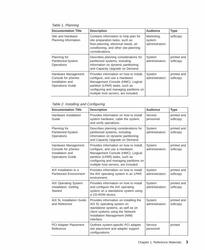
Table 1. Planning
Documentation Title Description Audience Type
Site and HardwarePlanning Information
Contains information to help plan forsite preparation tasks, such asfloor-planning, electrical needs, airconditioning, and other site-planningconsiderations.
Marketing,systemadministrators
softcopy
Planning forPartitioned-SystemOperations
Describes planning considerations forpartitioned systems, includinginformation on dynamic partitioningand Capacity Upgrade on Demand.
Systemadministrators
printed andsoftcopy
Hardware ManagementConsole for pSeriesInstallation andOperations Guide
Provides information on how to install,configure, and use a HardwareManagement Console (HMC). Logicalpartition (LPAR) tasks, such asconfiguring and managing partitions onmultiple host servers, are included.
Systemadministrators
printed andsoftcopy
Table 2. Installing and Configuring
Documentation Title Description Audience Type
Hardware InstallationGuide
Provides information on how to installsystem hardware, cable the system,and verify operations.
Servicepersonnel
printed andsoftcopy
Planning forPartitioned-SystemOperations
Describes planning considerations forpartitioned systems, includinginformation on dynamic partitioningand Capacity Upgrade on Demand.
Systemadministrators
printed andsoftcopy
Hardware ManagementConsole for pSeriesInstallation andOperations Guide
Provides information on how to install,configure, and use a HardwareManagement Console (HMC). Logicalpartition (LPAR) tasks, such asconfiguring and managing partitions onmultiple host servers, are included.
Systemadministrators
printed andsoftcopy
AIX Installation in aPartitioned Environment
Provides information on how to installthe AIX operating system in an LPARenvironment.
Systemadministrators
printed andsoftcopy
AIX Operating SystemInstallation: GettingStarted
Provides information on how to installand configure the AIX operatingsystem on a standalone system usinga CD-ROM device.
Systemadministrators
printed andsoftcopy
AIX 5L Installation Guideand Reference
Provides information on installing theAIX 5L operating system onstandalone systems, as well as onclient systems using the NetworkInstallation Management (NIM)interface.
Systemadministrators
printed andsoftcopy
PCI Adapter PlacementReference
Outlines system-specific PCI adapterslot placement and adapter supportconfigurations.
Servicepersonnel
printed
Chapter 1. Reference Materials 3
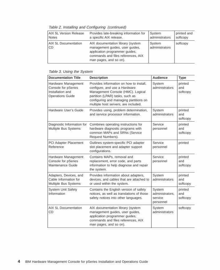
Table 2. Installing and Configuring (continued)
AIX 5L Version ReleaseNotes
Provides late-breaking information fora specific AIX release.
Systemadministrators
printed andsoftcopy
AIX 5L DocumentationCD
AIX documentation library (systemmanagement guides, user guides,application programmer guides,commands and files references, AIXman pages, and so on).
Systemadministrators
softcopy
Table 3. Using the System
Documentation Title Description Audience Type
Hardware ManagementConsole for pSeriesInstallation andOperations Guide
Provides information on how to install,configure, and use a HardwareManagement Console (HMC). Logicalpartition (LPAR) tasks, such asconfiguring and managing partitions onmultiple host servers, are included.
Systemadministrators
printedandsoftcopy
Hardware User’s Guide Provides using, problem determination,and service processor information.
Systemadministrators
printedandsoftcopy
Diagnostic Information forMultiple Bus Systems
Combines operating instructions forhardware diagnostic programs withcommon MAPs and SRNs (ServiceRequest Numbers).
Servicepersonnel
printedandsoftcopy
PCI Adapter PlacementReference
Outlines system-specific PCI adapterslot placement and adapter supportconfigurations.
Servicepersonnel
printed
Hardware ManagementConsole for pSeriesMaintenance Guide
Contains MAPs, removal andreplacement, error code, and partsinformation to help diagnose and repairthe system.
Servicepersonnel
printedandsoftcopy
Adapters, Devices, andCable Information forMultiple Bus Systems
Provides information about adapters,devices, and cables that are attached toor used within the system.
Systemadministrators
printedandsoftcopy
System Unit SafetyInformation
Contains the English version of safetynotices, as well as translations of thosesafety notices into other languages.
Systemadministrators,servicepersonnel
printedandsoftcopy
AIX 5L DocumentationCD
AIX documentation library (systemmanagement guides, user guides,application programmer guides,commands and files references, AIXman pages, and so on).
Systemadministrators
softcopy
4 IBM Hardware Management Console for pSeries Installation and Operations Guide
Chapter 2. Introducing the Hardware Management Console
The HMC uses its connection to one or more systems (referred to in this book asmanaged systems) to perform various functions, including the following:
v Creating and maintaining a multiple-partitioned environment
v Displaying a virtual operating system session terminal for each partition
v Displaying virtual operator panel values for each partition
v Detecting, reporting, and storing changes in hardware conditions
v Powering managed systems on and off
v Acting as a service focal point for service representatives to determine anappropriate service strategy and enable the Service Agent Call-Home capability
v Activating additional processor resources on demand
Managed System OperationsPartitioning provides users with the ability to configure a single computer into severalindependent systems. Each of these systems, called partitions, is capable of runningapplications in its own independent environment. This independent environmentcontains its own operating system, its own set of system processors, its own set ofsystem memory, and its own I/O adapters.
The HMC allows you to perform many hardware management tasks for your managedsystem, including configuring logical partitions. You can choose to operate yourmanaged system as a single server, or you can choose to run multiple partitions.
You can use the following types of partitioning: logical partitioning and the Full SystemPartition.
PartitioningLogical partitioning has no limitations to the number of hardware resources that arecontained in a partition. A partition could have any number of installed processorsassigned to it, limited only by the total number of installed processors. Similarly, apartition could have any amount of memory, limited only by the total amount of memoryinstalled. I/O adapters are physically installed in one of many I/O drawers in the system.However, with logical partitioning, any I/O adapter in any I/O drawer can be assigned toany partition.
Some systems have the ability to create affinity partitions. An affinity partition is aspecial type of logical partition, in that it has a close physical proximity to each of itsresources. Hardware resources for affinity partitioning, with the exception of I/O, aredefined by the HMC. When creating an affinity partition, the HMC automaticallydetermines which system resources are to be grouped together and allows you tochoose which type of grouping you want. The HMC then creates a profile for eachaffinity partition and a system profile that contains the affinity partitions for the managedsystem.
5
The operating system running in a partition is completely independent of any otheroperating system running in another partition. Operating system levels in each partitiondo not need to be the same, nor do the application levels.
By using partitions, for example, a company can test its program on one partition whiledeveloping the same program on another, all at the same time, all by using the samesystem. This ″same system″ partitioning method is more cost-effective, potentiallyeliminating the need for a separate test system.
For more information about partitions and their capabilities, see Chapter 4, “Partitioning”on page 19.
Service Focal PointService representatives use the Service Focal Point application to start and end theirservice calls and provide them with event and diagnostic information. The HMC canalso automatically notify service representatives of hardware failures by using a featurecalled Service Agent. You can configure the HMC to use Service Agent’s call-homefeature to send event information to your service representative.
The HMC must have a LAN connection to each partition (including the Full SystemPartition, if used) to collect partition errors. The HMC must also be connected to amodem and analog telephone line for the automatic notification process to functioncorrectly.
The Service Focal Point application must be configured so that the proper information issent. Also, whenever you make any changes to a system configuration, follow theguidelines in this book to ensure that changes are compatible with Service Focal Point.For more information about Service Focal Point, see Chapter 19, “Service Focal Point”on page 145.
6 IBM Hardware Management Console for pSeries Installation and Operations Guide
Chapter 3. Installing and Configuring the HMC
This chapter contains information about installing the HMC and configuring the servicesoftware.
Installing the Hardware Management ConsolePerform the following to install your HMC.
Position the HMC and MonitorCAUTION:Follow handling precautions provided with the unit.
Position the HMC and monitor at or near their desired location, using the followingguidelines:
v Use caution when lifting or moving the HMC.
v Use caution when lifting or moving the monitor.
v Leave enough space around the HMC to safely and easily complete the setupprocedures.
v Be sure to maintain at least 51 mm (2 inches) of space on the sides of the systemunit and 152 mm (6 inches) at the rear of the system unit to allow the system unit tocool properly. The front of the system requires a minimum of 76 mm (3 inches) ofspace. Blocking the air vents can cause overheating, which might result in amalfunction or permanent damage to the system unit.
v Place the HMC in a location where all necessary power outlets and networkconnections can safely be reached.
v Place the monitor in a stable and sturdy location.
Connect the CablesUse the following steps to connect the cables to your HMC. Look for the small icons onthe back of your HMC, which show where to attach the cables for the keyboard, mouse,and monitor.
1. Attach the monitor cable to the monitor connector, and tighten the screws.
2. If a label for the monitor was shipped with your system, attach the label to thebottom-right corner of the monitor.
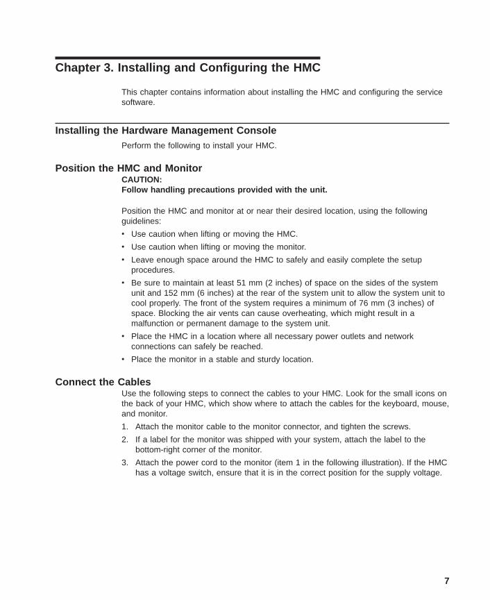
3. Attach the power cord to the monitor (item 1 in the following illustration). If the HMChas a voltage switch, ensure that it is in the correct position for the supply voltage.
7
Attention: Do not plug the power cords into the electrical outlet at this point.
4. Connect the mouse and keyboard to their connectors.
5. Connect the HMC serial cable to serial port HMC1 on the primary I/O book. For twoHMCs, connect the redundant HMC into serial port HMC2 on the primary I/O book.The following illustration shows the location of the serial ports on the back of the
8 IBM Hardware Management Console for pSeries Installation and Operations Guide
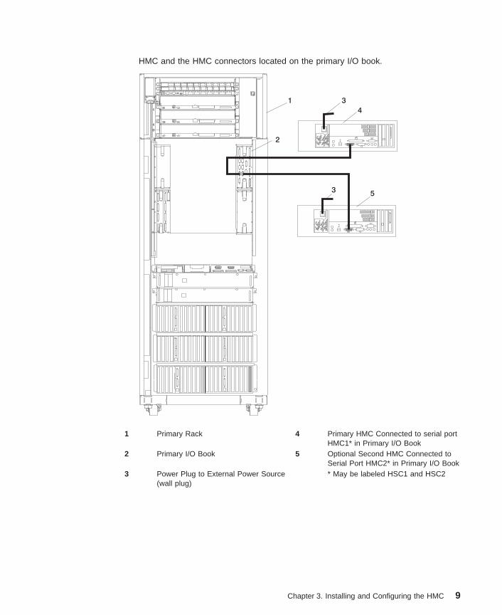
HMC and the HMC connectors located on the primary I/O book.
1 Primary Rack 4 Primary HMC Connected to serial portHMC1* in Primary I/O Book
2 Primary I/O Book 5 Optional Second HMC Connected toSerial Port HMC2* in Primary I/O Book
3 Power Plug to External Power Source(wall plug)
* May be labeled HSC1 and HSC2
Chapter 3. Installing and Configuring the HMC 9
The part numbers for the serial cables for the HMC are as follows:
Part Number and Description Position
Part Number 11P3955 6m cable 9 Position to 9 Position
Part Number 11P3956 15m cable 9 Position to 9 Position
Part Number 31L7196 15m cable 9 Position to 25 Position
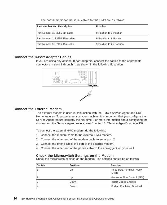
Connect the 8-Port Adapter CablesIf you are using any optional 8-port adapters, connect the cables to the appropriateconnectors in slots 1 through 4, as shown in the following illustration.
Connect the External ModemThe external modem is used in conjunction with the HMC’s Service Agent and CallHome features. To properly service your machine, it is important that you configure theService Agent feature correctly the first time. For more information about configuring themodem and the Service Agent feature, see Chapter 18, “Service Agent” on page 137.
To connect the external HMC modem, do the following:
1. Connect the modem cable to the external HMC modem.
2. Connect the other end of the modem cable to serial port 2.
3. Connect the phone cable line port of the external modem.
4. Connect the other end of the phone cable to the analog jack on your wall.
Check the Microswitch Settings on the ModemCheck the microswitch settings on the modem. The settings should be as follows:
Switch Position Function
1 Up Force Data Terminal Ready(DTR)
2 Up Hardware Flow Control (&E4)
3 Down Result Codes Enabled
4 Down Modem Emulation Disabled
10 IBM Hardware Management Console for pSeries Installation and Operations Guide
5 *Down Auto Answer Disabled
6 Up Maximum Throughput Enabled
7 Up Ready to Send (RTS) NormalFunctions
8 Down Enable Command Mode
9 Down Remote Digital Loopback TestEnabled
10 Up Dial-Up Line Enabled
11 Down Asynchronous Terminal (AT)Responses Enabled (ExtendedResponses Enabled)
12 *Down Asynchronous Operation
13 UP 28.8 KB Line Speed
14 Up
15 Up Carrier Detect (CD) and DataSet Ready (DSR) NormalFunctions
16 Up 2-Wire Leased Line Enabled
Note: * Only switches 5 and 12 are changed from the factory default settings.
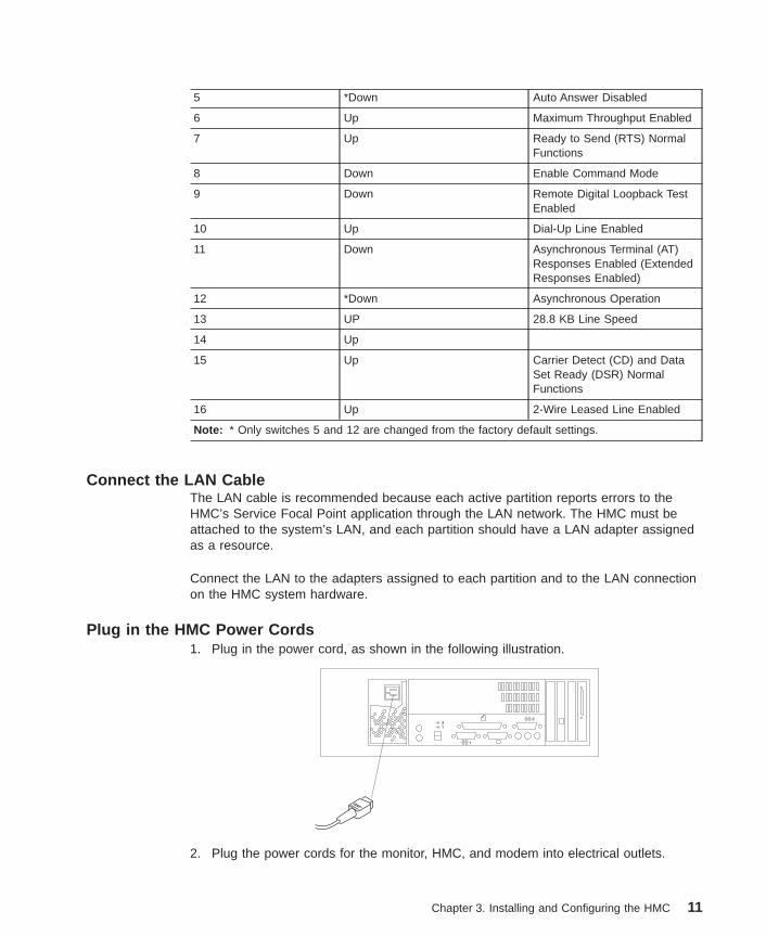
Connect the LAN CableThe LAN cable is recommended because each active partition reports errors to theHMC’s Service Focal Point application through the LAN network. The HMC must beattached to the system’s LAN, and each partition should have a LAN adapter assignedas a resource.
Connect the LAN to the adapters assigned to each partition and to the LAN connectionon the HMC system hardware.
Plug in the HMC Power Cords1. Plug in the power cord, as shown in the following illustration.
2. Plug the power cords for the monitor, HMC, and modem into electrical outlets.
Chapter 3. Installing and Configuring the HMC 11
Getting StartedUse the steps in this section to start using your HMC.
Change the Keyboard SettingsDuring the system boot, you are prompted to change the HMC keyboard settings. If youdo not take any action, this prompt times out in 30 seconds and defaults to an Englishkeyboard setting. If you only want to use an non-English keyboard setting, you canselect the language you want and disable this prompt for future sessions.
Log in to the HMCThe HMC is shipped with a predefined user ID and password. Both the user ID andpassword are case-sensitive and must be typed exactly as shown. This default user IDand password are as follows:
v ID: hscroot
v Password: abc123
When the console is powered on for the first time, use this user ID to log in. For moreinformation about user management and roles, see Chapter 12, “User Management” onpage 71. This hscroot user ID is a member of the System Administrator role.
After you power on your HMC, the HMC login window displays, and prompts you toenter your user ID and password.
Change the Predefined hscroot PasswordTo restrict access, change the predefined hscroot password immediately. To change thepredefined hscroot password, do the following:
1. In the Navigation area (the area on the left side of the screen), click the User icon.
2. In the Contents area (the area on the right side of the screen), right-click thehscroot icon.
3. Select Change Password .
4. Type the new password in the first field.
5. Confirm the new password by typing it again in the Retype new password field.
Change the Predefined Root-User Password on the HMCThe HMC is shipped with the following predefined root-user password:
passw0rd
The root-user ID and password cannot be used to log in to the console. However, theroot-user ID and password are needed to perform some maintenance procedures.
To control access to the HMC, do the following:
1. In the Navigation area (the area on the left side of the screen), select the User icon.
2. In the Contents area (the area on the right side of the screen), right-click the rooticon.
12 IBM Hardware Management Console for pSeries Installation and Operations Guide
3. Select Change Password .
4. Type the new password in the first field.
5. Confirm the new password by typing it again in the Retype new password field.
Check Your HMC Software VersionYou can use the HMC interface to check your current HMC software version.
To check, do the following:
1. Log in to the HMC as hscroot or as a user with System Administrator role.
2. At the top of HMC interface, select Help .
3. Select About Hardware Management Console . A window opens that displaysHMC software-level information.
For more information about updating the HMC code, see “Upgrading the HMCSoftware” on page 14.
Create UsersAfter you have logged in and changed both passwords, you are ready to createadditional HMC users. The additional users can be assigned different roles to controltheir access to different HMC tasks. For more information about user management androles, see Chapter 12, “User Management” on page 71.
Installing the HMC Interface after Replacing the Hard DriveIf you replace the HMC hard drive, you must re-install the HMC interface. To re-installthe HMC interface, do the following:
1. Power on your HMC.
2. When the HMC reboots, a window opens with the following options:
v Install/Recovery
v Upgrade
Select the Install/Recovery option by pressing F8.
3. Press F1 to confirm.
4. When the installation is complete, the DVD ejects from the drive. Remove theRecovery CD from the drive and close the DVD-RAM drive. Press Enter to rebootHMC.
Note: If there is a modem installed, ensure that it is powered on.
5. When the HMC reboots, if the KUDZU screen opens, immediately start theHardware Discovery Utility .
6. For each Hardware Removed window (if any), click Remove Configuration . Thistask logically removes hardware devices from the system configuration.
7. For each Hardware Added window, click Configure . This task configures thedevices. Most devices, such as modems, will require no additional settings. Added
Chapter 3. Installing and Configuring the HMC 13
devices like an Ethernet adapter will prompt you to migrate to an existing network. Ifthis occurs, click Migrate Existing Network .
8. The Keyboard Mapping Section window opens. There is a timer on the keyboardmapping selection screen. Select an applicable keyboard option for your locale. Youcan also select an appropriate language for your HMC interface. For moreinformation about changing the HMC interface language, see “Changing the HMCInterface Language” on page 50.
9. When the HMC finishes booting, reconfigure the HMC. For more information aboutconfiguring the HMC, see Chapter 7, “System Configuration” on page 39. If yourecorded the rexec, ssh, or scheduled operation facilities, reset them now.
Upgrading the HMC SoftwareThis section describes how to upgrade the HMC software to the latest release level. Ifyou recently purchased your HMC, it is preinstalled with the latest software.
If you need to upgrade the HMC software and do not follow these steps, you will losethe HMC’s configuration settings when the new software is installed. Before performingany upgrade task, you must perform the Backup Critical Console Data task to save thecurrent state of the HMC software to DVD.
Software upgrades on the HMC can be performed in two ways:
v Between major releases you can perform the Install Corrective Service task toupdate the HMC software. For more information about performing this task, see“Installing Corrective Service for the HMC” on page 134.
v To upgrade, you must perform an upgrade procedure. This upgrade process involvesa series of steps that ensures that configuration settings such as networkconfiguration are saved and restored after the upgrade operation.
To upgrade the HMC software from one release to another, do the following:
Prepare for the UpgradeTo prepare your HMC for the upgrade, you must record configuration information andback up console information. To prepare for the upgrade, do the following:
Check the Current HMC Software LevelFirst, you must determine your current HMC software version. To check, do thefollowing:
1. Login to the HMC as hscroot or as a user with System Administrator role. For moreinformation about user tasks and roles, see Chapter 12, “User Management” onpage 71.
2. Select Help at top of HMC console.
3. Select About Hardware Management Console .
A window opens that displays HMC software-level information. If you do not haveVersion 3, continue with the following steps.
14 IBM Hardware Management Console for pSeries Installation and Operations Guide
Record Current HMC Configuration InformationBefore you upgrade to the new version, you must first write down HMC configurationinformation. To record HMC configuration information, do the following:
1. In the Navigation area, click the HMC Maintenance folder.
2. In the Navigation area, select System Configuration .
3. In the Contents area, select Scheduled Operations . The Scheduled Operationswindow opens.
4. Select Sort .
5. Select By Object .
6. Select each object. Record the following details:
v Object Name
v Schedule Date
v Operation Time (displayed in 24-hour format)
v Repetitive. If repetitive is YES, do the following:
a. Select View .
b. Select Schedule Details .
c. Record the interval information.
d. Close the Scheduled Operations window.
7. Repeat the previous step for each scheduled operation.
8. Close the Scheduled Operations window.
9. Back up the managed system information and record the backup file names foreach managed system. In the Navigation area, click the Server and Partitionfolder.
10. In the Contents area, double-click Server Management .
11. In the Contents area, right-click the managed system and select Profile Data –>Backup .
12. Type a backup file name and record this information.
13. Click OK.
14. Repeat steps 11-13 for each managed system.
15. Check the rexec and ssh settings. In the Navigation area, click the SoftwareMaintenance icon.
16. In the Navigation area, click the System Configuration icon.
17. In the Contents area, click Enable/Disable Remote Command Execution .
18. Record the settings of the following two options:
v Enable remote command execution using the rexec facility
v Enable remote command execution using the ssh facility
For more information about using these facilities, refer to the documentationshipped with your operating system.
Chapter 3. Installing and Configuring the HMC 15
Back Up Critical Console InformationNext, you must back up critical console information. To back up critical consoleinformation, do the following:
1. If you previously backed up the HMC during the HMC software installation, removethe old label from the DVD.
2. Ensure that the DVD is not write protected by examining the switch in the lower-leftcorner on the front. The switch should be in the lower position.
3. Insert either the DVD into the HMC’s DVD-RAM drive.
4. In the Contents area, click Backup Critical Console Data .
5. Click Continue and wait for the HMC to complete the task.
6. Click OK.
7. Remove the DVD from the drive and write the date, time and code level on theDVD.
Upgrade the HMC SoftwareThis section describes how to upgrade your HMC interface.
1. Log in to your HMC as hscroot .
2. In the Navigation area, double-click the Software Maintenance folder.
3. In the Contents area, select HMC.
4. In the Contents area, click Save Upgrade Data .
5. Click Hard Drive .
6. Click Continue .
7. Select Continue again to start the task. Wait for the task to complete. If the SaveUpgrade Data task fails, contact software support before proceeding. Do notcontinue the upgrade process if the Save Upgrade Data task fails.
8. Click OK.
9. Insert the HMC Recovery CD into the DVD-RAM drive.
10. Reboot the HMC Console. Select Console menu option, then select Exit .
11. Click Exit now .
12. The Exit Hardware Management Console window opens. Click Reboot Console .
13. When the HMC reboots, a window opens with the following options:
v Install/Recovery
v Upgrade
Select the Upgrade option by pressing F1.
14. Press F1 again to confirm.
15. When the upgrade is complete, the DVD ejects from the drive. Remove theRecovery CD from the drive and close the DVD-RAM drive. Press Enter to rebootthe HMC.
Note: If there is a modem installed, ensure that it is powered on.
16. When the HMC reboots, if the KUDZU screen appears, immediately press Enter tostart the Hardware Discovery Utility.
16 IBM Hardware Management Console for pSeries Installation and Operations Guide
17. For each Hardware Removed window (if any), click Remove Configuration . Thistask logically removes hardware devices from the system configuration.
18. For each Hardware Added window, click Configure . This task configures thedevices. Most devices, such as modems, require no additional settings. Addeddevices such as an Ethernet adapter will prompt you to migrate to an existingnetwork. If this occurs, click Migrate Existing Network .
19. The Keyboard Mapping Section window opens. There is a timer on the keyboardmapping selection screen. Select an applicable keyboard option for your locale.
20. When the HMC finishes booting, reconfigure the new version. For more informationabout configuring the HMC, see Chapter 7, “System Configuration” on page 39. Ifyou recorded the rexec , ssh , or scheduled operation facilities, reset them now.
Setting Up Your HMC Software for ServicePerform the following steps to configure your managed system for service.
1. Complete the required planning information in pSeries Planning forPartitioned-System Operations.
2. Log in to the HMC.
3. Configure the HMC’s date and time. For more information about setting the HMC’sdate and time, see “Setting and Viewing the Console Date and Time” on page 39.
4. Configure the network settings on your HMC. For more information about setting upthe network, see “Customizing Network Settings” on page 40.
5. Reboot the HMC. For more information about rebooting the HMC, see “ShuttingDown, Rebooting and Logging Out of the HMC” on page 29.
6. Create a partition and install an operating system on it. For more information aboutcreating partitions, see “Creating Logical Partitions” on page 99. For moreinformation about installing an operating system on a partition, refer to theinstallation information shipped with your operating system.
7. Verify that Service Focal Point is operating properly by generating a test error. Formore information about testing Service Focal Point’s error reporting, see “TestingError Reporting” on page 145.
8. Configure the Inventory Scout application. For more information about configuringInventory Scout, see “Configuring the Inventory Scout Services Profile” on page 65.
9. Configure the Service Agent application. For more information about configuringService Agent, see “Configuring and Using Service Agent” on page 139.
Setting Up Service AuthorityA service representative can install firmware upgrades on the managed server.Firmware upgrades are done at the system level, not on a per-partition basis. Afirmware upgrade can be performed from a partition that is running AIX or from theservice processor menus.
When partitions are being created, it is recommended that one partition be givenservice authority. Service technicians use the partition designated as having service
Chapter 3. Installing and Configuring the HMC 17
authority to perform system firmware upgrades and set other system policy parameterswithout having to power off the managed system. All other partitions must be shut downbefore the firmware upgrade is initiated.
The partition that has service authority must also have access to the firmware upgradeimage. If the firmware upgrade image is going to be read from diskettes, the diskettedrive must be assigned to the partition that has service authority. If you aredownloading the firmware upgrade from the network, download it to the partition thathas service authority.
For more information about how to set service authority on a partition, read “SettingService Authority” on page 121.
If you powered on with the Full System Partition, you do not have to take additionalsteps to prepare for firmware upgrades.
18 IBM Hardware Management Console for pSeries Installation and Operations Guide
Chapter 4. Partitioning
This chapter provides an overview of partitions and how a partitioned system ismanaged.
Partitioning your system is similar to partitioning a hard drive. When you partition a harddrive, you divide a single physical hard drive so that the operating system recognizes itas a number of separate logical hard drives. You have the option of dividing thesystem’s resources by using the HMC to partition your system. On each of thesedivisions, called partitions, you can install an operating system and use each partitionas you would a separate physical system.
Types of PartitionsThe HMC allows you to use two types of partitions: logical partitions, and the FullSystem Partition.
Logical PartitionsLogical partitions are user-defined system resource divisions. Users determine thenumber of processors, memory, and I/O that a logical partition can have when active.
Some systems are equipped to use affinity partitions. An affinity partition is a specialtype of logical partition. Affinity partitions are divisions of system-defined resources thathave a close physical proximity to each other. When you decide to create an affinitypartition, the system determines the number of processors and memory that a partitioncan have, but the user determines the I/O requirements for each of these partitions.
Full System PartitionA special partition called the Full System Partition assigns all of your managed system’sresources to one large partition. The Full System Partition is similar to the traditional,non-partition method of operating a system. Because all resources are assigned to thispartition, no other partitions can be started when the Full System Partition is running.Likewise, the Full System Partition cannot be started while other partitions are running.
The HMC allows you to easily switch from the Full System Partition to logical partitions.The actual setup of the operating system in a partition may require some carefulplanning to ensure no conflicts exist between the two environments.
Benefits of PartitioningPartitioning provides greater flexibility when deploying multiple workloads on servers,providing better management, improved availability, and more efficient use of resources.
v Consolidate Servers : A server with sufficient processing capacity that is capable ofbeing partitioned can address the need for server consolidation by logicallysubdividing the server into a number of separate, smaller systems. In this way,application-isolation needs can be met in a consolidated environment, with the
19
additional benefits of reduced floor space, a single point of management, and easierredistribution of resources as workloads change.
v Merge Production and Test Environments : Partitioning enables separate partitionsto be allocated for production and test systems, eliminating the need to purchaseadditional hardware and software. When testing has been completed, the resourcesallocated to the test partition can be returned to the production partition or elsewhereas required. As new projects are developed, they can be built and tested on thesame hardware on which they will eventually be deployed.
v Consolidate Multiple Versions of the Same Operating System : A single systemcan have different versions of the operating system installed to accommodatemultiple application requirements. Furthermore, a partition can be created to testapplications under new versions of the operating system prior to upgrading theproduction environments. Instead of having a separate server for this function, aminimum set of resources can be temporarily used to create a new partition wherethe tests are performed. When the partition is no longer needed, its resources can beincorporated back into the other partitions.
v Consolidate Applications Requiring Different Time Zone Settings : Partitioningenables multiple regional workloads to be consolidated onto a single server. Thedifferent workloads can run in different partitions, with different operating systems, aswell as with different time and date settings. For example, workloads for operationsbased in San Francisco and New York can run in different partitions on a singleserver. The evening batch workload, maintenance, or upgrade for the New Yorkoperation does not affect those of the San Francisco operation.
Managing a Partitioned SystemUsing the HMC to manage your partitioned system, different managed-object typesexist within the user interface. You can perform management functions by selecting theappropriate object type and then selecting an appropriate task. The main types ofobjects are managed systems, partitions, and profiles.
Managed SystemsManaged systems are the systems that are physically attached to and managed by theHMC. The HMC can perform tasks that affect the entire managed system, such aspowering the system on and off. You can also create partitions and profiles within eachmanaged system. These partitions and profiles define the way that you configure andoperate your partitioned system.
PartitionsWithin your managed system, you can assign resources to create partitions. Eachpartition runs a specific instance of an operating system. The HMC can perform taskson individual partitions. These tasks are similar to those you can perform on traditional,non-partitioned servers. For example, you can use the HMC to start the operatingsystem and access the operating system console.
Because the HMC provides a virtual terminal for each partition, a terminal window canbe opened for each console. This virtual terminal can be used for software installation,system diagnostics, and system outputs. The managed system firmware and device
20 IBM Hardware Management Console for pSeries Installation and Operations Guide
drivers provide the redirection of the data to the virtual terminal. For more informationabout the virtual terminal window, see Chapter 16, “Virtual Terminal Window” onpage 127.
ProfilesA profile defines a configuration setup for a managed system or partition. The HMCallows you to create multiple profiles for each managed system or partition. You canthen use the profiles you created to start a managed system or partition in a particularconfiguration.
You can create the following types of profiles:
Partition ProfilesA partition does not actually own any resources until it is activated; resourcespecifications are stored within partition profiles. The same partition canoperate using different resources at different times, depending on the profileyou activate.
When you activate a partition, you enable the system to create a partitionusing the set of resources in a profile created for that partition. For example, alogical partition profile might indicate to the managed system that its partitionrequires 3 processors, 2 gigabytes of memory, and I/O slots 6, 11 and 12when activated.
You can have more than one profile for a partition. However, you can onlyactivate a partition with one profile at a time. Additionally, affinity partitions andlogical partitions cannot be active at the same time.
Partition profiles are not affected by changes you make using the DynamicLogical Partitioning feature. If you want permanent changes, you must thenreconfigure partition profiles manually. For example, if your partition profilespecifies that you require two processors and you use Dynamic LogicalPartitioning to add a processor to that partition, you must change the partitionprofile if you want the additional processor to be added to the partition the nexttime you use the profile.
System ProfilesUsing the HMC, you can create and activate often-used collections ofpredefined partition profiles. A collection of predefined partition profiles is calleda system profile. The system profile is an ordered list of partitions and theprofile that is to be activated for each partition. The first profile in the list isactivated first, followed by the second profile in the list, followed by the third,and so on.
The system profile helps you change the managed systems from one completeset of partitions configurations to another. For example, a company might wantto switch from using 12 partitions to using only four, every day. To do this, thesystem administrator deactivates the 12 partitions and activates a differentsystem profile, one specifying four partitions.
When you create a group of affinity partitions, the HMC automatically creates asystem profile that includes all of the affinity partitions that you created.
Chapter 4. Partitioning 21

22 IBM Hardware Management Console for pSeries Installation and Operations Guide
Chapter 5. Preparing for Partitioning
This chapter helps you prepare for a multiple-partitioned environment, includinginformation about requirements, host name considerations, and managed systemoperating states.
Partitioning RequirementsThis section contains information about the requirements you must have in order tocreate partitions.
Overall RequirementsYou should do the following before creating partitions:
v Record the required subnet mask, any gateway information, and address of yourDNS server (if used).
v Check that you have a suitable LAN (hub or switch and cables) to connect to eachHMC and each network adapter used by partitions.
v Record the TCP/IP names and addresses to be resolved by a DNS server, or to beentered into the /etc/hosts file in each partition, and on the HMC.
v Locate the HMC in a suitable position so that the serial cable can be physicallyconnected to the managed system.
v An analog telephone port is close to the HMC location to connect the modem.
Before you start using partitioning, you must determine the following:
v Your current resources for each partition
v The operating system host name for each partition
v The partition you want to use for service actions
Assignable Resources for Logical PartitioningFor logical partitions, you must assign resources by creating partition profiles. Use thefollowing guidelines for assigning resources in logical partition profiles.
ProcessorsEach processor installed and configured on your system can be individually assigned toa logical partition. You must assign at least one processor to each logical partition.
MemoryThe HMC can assign memory to a logical partition in increments of 256 MB, with aminimum of 256 MB per partition. One GB is equal to 1024 MB. This section describesthe HMC’s various logical partition memory considerations.
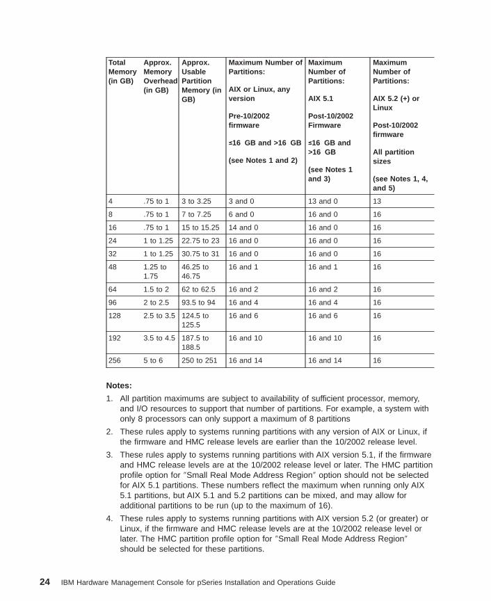
Logical Partition Memory Usage: The system requires some memory overheadwhen it creates logical partitions. Use the following table to help you determine howmuch memory overhead the system needs for partitioning. You can also use this tableto determine the maximum number of partitions you can create.
23
TotalMemory(in GB)
Approx.MemoryOverhead(in GB)
Approx.UsablePartitionMemory (inGB)
Maximum Number ofPartitions:
AIX or Linux, anyversion
Pre-10/2002firmware
≤16 GB and >16 GB
(see Notes 1 and 2)
MaximumNumber ofPartitions:
AIX 5.1
Post-10/2002Firmware
≤16 GB and>16 GB
(see Notes 1and 3)
MaximumNumber ofPartitions:
AIX 5.2 (+) orLinux
Post-10/2002firmware
All partitionsizes
(see Notes 1, 4,and 5)
4 .75 to 1 3 to 3.25 3 and 0 13 and 0 13
8 .75 to 1 7 to 7.25 6 and 0 16 and 0 16
16 .75 to 1 15 to 15.25 14 and 0 16 and 0 16
24 1 to 1.25 22.75 to 23 16 and 0 16 and 0 16
32 1 to 1.25 30.75 to 31 16 and 0 16 and 0 16
48 1.25 to1.75
46.25 to46.75
16 and 1 16 and 1 16
64 1.5 to 2 62 to 62.5 16 and 2 16 and 2 16
96 2 to 2.5 93.5 to 94 16 and 4 16 and 4 16
128 2.5 to 3.5 124.5 to125.5
16 and 6 16 and 6 16
192 3.5 to 4.5 187.5 to188.5
16 and 10 16 and 10 16
256 5 to 6 250 to 251 16 and 14 16 and 14 16
Notes:
1. All partition maximums are subject to availability of sufficient processor, memory,and I/O resources to support that number of partitions. For example, a system withonly 8 processors can only support a maximum of 8 partitions
2. These rules apply to systems running partitions with any version of AIX or Linux, ifthe firmware and HMC release levels are earlier than the 10/2002 release level.
3. These rules apply to systems running partitions with AIX version 5.1, if the firmwareand HMC release levels are at the 10/2002 release level or later. The HMC partitionprofile option for ″Small Real Mode Address Region″ option should not be selectedfor AIX 5.1 partitions. These numbers reflect the maximum when running only AIX5.1 partitions, but AIX 5.1 and 5.2 partitions can be mixed, and may allow foradditional partitions to be run (up to the maximum of 16).
4. These rules apply to systems running partitions with AIX version 5.2 (or greater) orLinux, if the firmware and HMC release levels are at the 10/2002 release level orlater. The HMC partition profile option for ″Small Real Mode Address Region″should be selected for these partitions.
24 IBM Hardware Management Console for pSeries Installation and Operations Guide

5. AIX 5.2, when run with the Small Real Mode Address Region profile option,requires that the maximum memory setting is no greater than 64 times the minimummemory setting. For example, if the minimum memory setting is 256MB, then themaximum memory setting should not be greater than 16GB. If you violate thiscondition, AIX does not start.
Real Mode Address Region (RMO) Memory Considerations: There are somespecial memory options to consider when assigning memory to a partition.
Small Real Mode Address Region: When you create a partition profile and select thememory sizes, you can select a box called Small Real Mode Address Region. Thisoption allows you to:
v Use managed system memory efficiently
v Avoid some of the memory allocation constraints associated with large partitions
To use the Small Real Mode Address Region option, you must have either Linux or AIX5.2 installed in the partition. If you check the Small Real Mode box and have therequired operating system on your partition, you do not have to follow the followingmemory boundary rules.
AIX 5.1 may not boot in a partition with the Small Real Mode Address Region optionselected, because AIX 5.1 requires a Real Mode Address Region that scales with thesize of the overall partition. If you meet these operating system requirements and checkthe Small Real Mode Address Region box, then the following memory allocationrestrictions do not apply.
Large Real Mode Address Region: If you do not select the Small Real Mode AddressRegion option, then when you assign your minimum, desired, and maximum memoryamounts in the partition profile, all three memory values will be constrained to be withina specific range. Each range is associated with a scalable Real Mode Address Regionof a particular size (256 MB, 1 GB, and 16 GB). The Real Mode Address Region size isautomatically determined by the maximum partition memory size that you specify.These memory ranges are defined in the following table:
Maximum Memory Size (inGB)
Real Mode Address Regionsize (in GB)
Partition Memory Range (inGB)
Up to 4 .25 .25 to 4
4.25 to 16 1 1 to 16
16.25 to 256 16 16 to 256
Because large Real Mode Address Regions have more constraints when placed inmemory, use the following guidelines when you are planning to create partitions that donot use the Small Real Mode Address Region option:
v Start all the partitions that are greater than 16 GB in size before starting all thepartitions that are less than or equal to 16 GB in size. If you activate a partition thatis greater than 16 GB last, it may not start.
v If all your partitions are greater than 16 GB in size, start the largest partition last.
Chapter 5. Preparing for Partitioning 25
I/O DevicesI/O is assignable to a given partition on a PCI adapter-slot basis.
Because each partition requires its own separate boot device, the system must have atleast one boot device and associated adapter per running partition.
Each partition should have at least one network adapter, although this is not mandatory.In addition to providing a network connection, the connection is also needed to providethe capability for HMC service functions. For more information , see “CustomizingNetwork Settings” on page 40.
For more information about a specific device and its capabilities, see the documentationshipped with that device. For a list of supported adapters and a detailed discussionabout adapter placement, refer to the PCI Adapter Placement Reference, order numberSA38-0538.
Assignable Resources for Affinity PartitioningYou must assign I/O resources to your affinity partitions by creating partition profiles.
Processors and MemoryThe HMC pre-allocates processors and memory to affinity partitions. You can choose tocreate either 4-processor affinity partitions or 8-processor affinity partitions. If you have32 processors on your system, choosing a 4-processor group allows you to create up toeight affinity partitions. Likewise, an 8-processor group allows you to create up to fouraffinity partitions. You cannot define 4-processor groups and 8-processor groups at thesame time.
I/O DevicesThe user allocates I/O to each affinity partition. I/O is assignable to a given partition ona PCI adapter-slot basis. You can also dynamically reassign I/O between affinitypartitions.
Because each partition requires its own separate boot device, the system must have atleast one boot device and associated adapter per partition.
Each partition should have one network adapter, although this is not mandatory. Inaddition to providing a network connection, the connection is also needed to provide thecapability for HMC service functions. For more information, see “Customizing NetworkSettings” on page 40.
For more information about a specific device and its capabilities, see the documentationprovided with that device. For a list of supported adapters and a detailed discussionabout adapter placement, refer to the PCI Adapter Placement Reference, order numberSA38-0538.
26 IBM Hardware Management Console for pSeries Installation and Operations Guide
Assigning a Host Name to Your PartitionEach partition, including the Full System Partition, must have a unique host name thatcan be resolved. Host names cannot be reused between the Full System Partition andthe logical partitions. If you need to change the the host name of the partition manually,you may need to update the Network Settings on the HMC. You will need to update if a″short″ partition name is used or if a DNS server is not used. For more informationabout changing the host name manually, see“Changing a Partition Host NameManually” on page 233. See “Customizing Network Settings” on page 40 to determine ifany additional changes are needed.
Operating StatesThe HMC Contents area displays an operating state for the managed system.
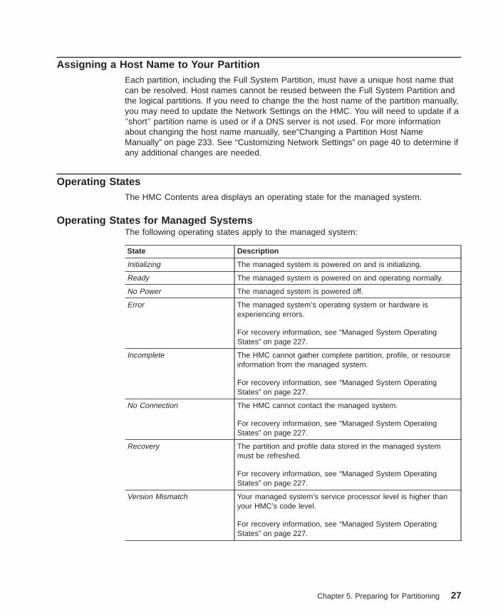
Operating States for Managed SystemsThe following operating states apply to the managed system:
State Description
Initializing The managed system is powered on and is initializing.
Ready The managed system is powered on and operating normally.
No Power The managed system is powered off.
Error The managed system’s operating system or hardware isexperiencing errors.
For recovery information, see “Managed System OperatingStates” on page 227.
Incomplete The HMC cannot gather complete partition, profile, or resourceinformation from the managed system.
For recovery information, see “Managed System OperatingStates” on page 227.
No Connection The HMC cannot contact the managed system.
For recovery information, see “Managed System OperatingStates” on page 227.
Recovery The partition and profile data stored in the managed systemmust be refreshed.
For recovery information, see “Managed System OperatingStates” on page 227.
Version Mismatch Your managed system’s service processor level is higher thanyour HMC’s code level.
For recovery information, see “Managed System OperatingStates” on page 227.
Chapter 5. Preparing for Partitioning 27
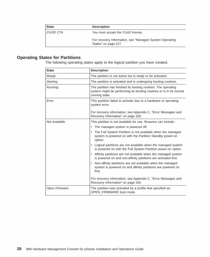
State Description
CUOD CTA You must accept the CUoD license.
For recovery information, see “Managed System OperatingStates” on page 227.
Operating States for PartitionsThe following operating states apply to the logical partition you have created.
State Description
Ready The partition is not active but is ready to be activated.
Starting The partition is activated and is undergoing booting routines.
Running The partition has finished its booting routines. The operatingsystem might be performing its booting routines or is in its normalrunning state.
Error This partition failed to activate due to a hardware or operatingsystem error.
For recovery information, see Appendix C, “Error Messages andRecovery Information” on page 165.
Not Available This partition is not available for use. Reasons can include:
v The managed system is powered off.
v The Full System Partition is not available when the managedsystem is powered on with the Partition Standby power-onoption.
v Logical partitions are not available when the managed systemis powered on with the Full System Partition power-on option.
v Affinity partitions are not available when the managed systemis powered on and non-affinity partitions are activated first.
v Non-affinity partitions are not available when the managedsystem is powered on and affinity partitions are powered onfirst.
For recovery information, see Appendix C, “Error Messages andRecovery Information” on page 165.
Open Firmware The partition was activated by a profile that specified anOPEN_FIRMWARE boot mode.
28 IBM Hardware Management Console for pSeries Installation and Operations Guide
Chapter 6. User Environment
This chapter discusses the user environment and Hardware Management Console(HMC) applications.
Using the Login WindowThe HMC provides a predefined user ID called hscroot. The hscroot password isabc123 . This hscroot user ID is a member of the System Administrator role. When theconsole is powered on for the first time, use this user ID to log in. After you are loggedin, you can create additional users.
After you power on your HMC, the HMC login window displays first, and prompts you toenter your user ID and password.
Service representatives may request that you create a special user ID that has theService Representative role, enabling them to log in to perform service functions. Formore information about creating users and assigning roles, see Chapter 12, “UserManagement” on page 71.
Shutting Down, Rebooting and Logging Out of the HMCThis task allows you to shut down, reboot and log out of the HMC interface.
To log out of the HMC interface, do the following:
1. In the main menu, select Console .
2. Select Exit . At this point, you can choose to save the state of the console for thenext session by clicking the box next to the option.
3. Select Exit Now .
4. When you exit from your HMC session, you can choose to shut down, reboot, or logout of your session. The following is a description of each option:
ShutdownPowers off the HMC system
RebootShuts down the HMC system and then reboots it to the login prompt
Logout Returns the user to the login prompt without shutting down the HMCsystem
29
HMC System Management EnvironmentThe HMC system management environment allows you to manage your managedsystems. The HMC interface is based on the AIX Web-based System Manager.
When you log in to the HMC, the HMC management window opens, and themanagement environment is already selected. This window is divided into theNavigation area and the Contents area.
The panel on the left (the Navigation area) displays a hierarchy of icons that representcollections of systems, individual systems, managed resources, and tasks. EachNavigation area folder identifies a collection of related applications. Each icon in thesefolders identifies an application. At the highest point, or root of the tree, is theManagement Environment. The Management Environment contains one or more hostsystem applications that are managed by the console. Each system application containsits own collection of applications that contain managed objects, tasks, and actions for arelated set of system entities or resources.
The panel on the right (the Contents Area) displays results based on the item youselect in the Navigation area. When you click on an application in the Navigation area,the Contents area displays the tasks you can perform using that application.
Each HMC contains the following set of application groups:
v System Manager Security
v Server and Partition
v Software Maintenance
v HMC Management
v HMC Maintenance
v Service Applications
Each HMC contains the following set of application icons:
v System Manager Security
v Server Management
v System Configuration
v Users
v Frame
v HMC
v Inventory Scout Services
v Service Agent
v Service Focal Point
v Problem Determination
Using Multiple HMCsYou can use one HMC to view and manage other HMCs by adding the additional HMCsto the Navigation area.
30 IBM Hardware Management Console for pSeries Installation and Operations Guide
You can also connect two HMCs to the same managed system. In this configuration,either HMC can perform tasks on that managed system. For more information aboutusing multiple HMCs, see Chapter 11, “Using Two HMCs Connected to One ManagedSystem” on page 69.
Using Multiple Managed Systems Connected to One HMCYou can connect more than one managed system to an HMC. When a managedsystem is connected to an HMC, it displays in the Navigation area. You can also useyour HMC to manage a frame of managed systems.
HMC Application OverviewThis section provides an overview of each application’s functions. For detailedinformation, see the chapter that discusses each application.
System Manager Security
System Manager Security provides for the secure operation of the HMC in client-servermode. System Manager Security is based on Public Key Encryption, the Secure SocketLayer (SSL) protocol, and the Pluggable Authentication Module (PAM) authenticationpolicy method. In the System Manager Security operation, the managed machines areservers and the managed users are clients.
Servers and clients communicate over the SSL protocol, which provides serverauthentication, data encryption, and data integrity. The client manages the server usingan account on that system and authenticates to the System Manager server by sendingthe user ID and password. Users of the System Manager Security application must belogged in to the HMC locally to ensure security during configuration.
For more information about using this application, see Chapter 9, “System ManagerSecurity” on page 59.
Server and Partition Application GroupThe Server and Partition application folder contains the Server Management application.
Server Management
The Server Management application manages all partition-related activities. Use theServer Management application to create, maintain, activate, and delete partitions. Youcan also use this application to power managed systems on and off.
Chapter 6. User Environment 31
For more information about using this application, see Chapter 15, “Server ManagementTasks” on page 99.
Software Maintenance Application GroupThe Software Maintenance folder contains the Software Maintenance applications.
Frame
The Frame software maintenance application allows you to receive and install correctiveservice for a frame.
For more information about using this application, see Chapter 17, “SoftwareMaintenance for the HMC and the Frame” on page 133.
HMC
The HMC software maintenance application allows you to save and back up importantHMC-related information and format removable media. You can also install correctiveservice on the HMC.
For more information about using this application, see Chapter 17, “SoftwareMaintenance for the HMC and the Frame” on page 133.
HMC Management Application GroupThe HMC Management folder contains the Users application.
Users
The Users application controls user access to the HMC. You can assign one role toeach user you create. Different roles allow the user to perform different tasks in theHMC environment.
For more information about using this application, see Chapter 12, “User Management”on page 71.
HMC Maintenance Application GroupThe HMC Maintenance application folder contains applications related to setting up andmaintaining the HMC environment.
32 IBM Hardware Management Console for pSeries Installation and Operations Guide
System Configuration
The System Configuration application allows you to do the following:
v Set the console’s date and time
v Enter and check HMC network information
v View console events
v Schedule routine backups
v Enable and disable remote commands
v Configure serial adapters
v Enable remote virtual terminal connections
v Change the HMC interface language
For more information about using this application, see Chapter 7, “SystemConfiguration” on page 39.
Service Applications GroupThe service applications folder contains applications used to service both the HMC andmanaged system.
Problem Determination
Service representatives have access authority to use this application to view anddiagnose HMC problems. This application is available to service representatives only.
Inventory Scout Services
Inventory Scout Services is a tool that surveys the managed system for hardware andsoftware information. This tool also provides a customized report indicating the latestmicrocode level. Inventory Scout Services helps users to keep track of softwareupdates and patches on managed systems.
For more information about using this application, see Chapter 10, “Inventory ScoutServices” on page 65.
Chapter 6. User Environment 33
Service Agent
The Service Agent application accepts hardware errors from the Service Focal Point.Service Agent reports serviceable events, assuming they meet certain criteria forcriticality, for service without requiring customer intervention.
Service Agent enables the following:
v Automatic problem reporting; service calls can be placed without customerintervention
v Automatic sending of extended vital product data to IBM
v Automatic customer notification
v Network environment support with minimum number of telephone lines for modems
For more information about using this application, see Chapter 18, “Service Agent” onpage 137.
Service Focal Point
Service representatives and system administrators use Service Focal Point to viewoperating system error logs.
For more information about using this application, see Chapter 19, “Service Focal Point”on page 145.
HMC Management WindowThe HMC menu bar on the HMC management window displays all of the operationsperformed on the console and managed objects. The menus are organized as follows:
Console MenuThe Console Menu contains choices that control the console. It allows you to do thefollowing tasks:
v Add and remove host systems from the management environment, including otherHMCs
v Save console preferences
v Specify whether to automatically attempt to log in to a host with a stored password
v View the console session log
v Exit the console
34 IBM Hardware Management Console for pSeries Installation and Operations Guide
Object MenuThe name of the Object Menu changes to indicate the type of resource managed by thecurrent application you have selected. For example, when you select the PartitionManagement application, the Object Menu title becomes Partitions. The Object Menucontains general choices and actions for an application that do not require you to selectspecific object actions. Typically, actions for creating new resource objects are locatedin the Object Menu. When a new application is selected, the contents of the ObjectMenu are updated.
Selected MenuThe Selected Menu contains those actions for an application that require you to selectwhich managed objects an action is to apply to, such as Open , Properties , Copy ,Delete , or Start . When you select a new managed object, the contents of the SelectedMenu are updated.
View MenuThe View Menu contains choices for navigating, such as Back , Forward , and Up OneLevel . It also includes choices for customizing the console in the Show submenu. Forexample, you can select to show or hide the tool bar and status bar. The View Menuincludes options that control how objects are presented. For example, if the applicationprovides a choice of views, such as Large Icon, Small Icon, Details, and Tree, thesechoices are listed here. If the application only supports a single view, no view choicesare listed. When an application is displaying an icon or Details view, the View Menuincludes choices for sorting and filtering the container.
Window MenuThe Window Menu contains actions for managing sub-windows in the consoleworkspace. New Window creates a new console sub-window in the workspace. Otherchoices control how all console sub-windows are presented.
Help MenuThe Help Menu lists user-assistance choices. You can view help contents and searchfor help on a particular topic.
The Documentation BrowserThe icon on the lower left of the screen launches a documentation browser. Use it toview HMC documentation on your HMC interface.
HMC Keyboard ControlThe HMC can be used with or without a pointing device, such as a mouse. If youchoose not to use a pointing device, you can move among controls and menus usingonly the keyboard.
Using Mnemonics and ShortcutsYou can access menu functions using the following keyboard methods:
Chapter 6. User Environment 35
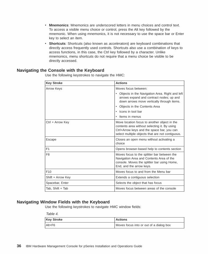
v Mnemonics : Mnemonics are underscored letters in menu choices and control text.To access a visible menu choice or control, press the Alt key followed by themnemonic. When using mnemonics, it is not necessary to use the space bar or Enterkey to select an item.
v Shortcuts : Shortcuts (also known as accelerators) are keyboard combinations thatdirectly access frequently used controls. Shortcuts also use a combination of keys toaccess functions, in this case, the Ctrl key followed by a character. Unlikemnemonics, menu shortcuts do not require that a menu choice be visible to bedirectly accessed.
Navigating the Console with the KeyboardUse the following keystrokes to navigate the HMC:
Key Stroke Actions
Arrow Keys Moves focus between:
v Objects in the Navigation Area. Right and leftarrows expand and contract nodes; up anddown arrows move vertically through items.
v Objects in the Contents Area
v Icons in tool bar
v Items in menus
Ctrl + Arrow Key Move location focus to another object in thecontents area without selecting it. By usingCtrl+Arrow keys and the space bar, you canselect multiple objects that are not contiguous.
Escape Closes an open menu without activating achoice
F1 Opens browser-based help to contents section
F8 Moves focus to the splitter bar between theNavigation Area and Contents Area of theconsole. Moves the splitter bar using Home,End, and the arrow keys.
F10 Moves focus to and from the Menu bar
Shift + Arrow Key Extends a contiguous selection
Spacebar, Enter Selects the object that has focus
Tab, Shift + Tab Moves focus between areas of the console
Navigating Window Fields with the KeyboardUse the following keystrokes to navigate HMC window fields:
Table 4.
Key Stroke Actions
Alt+F6 Moves focus into or out of a dialog box
36 IBM Hardware Management Console for pSeries Installation and Operations Guide
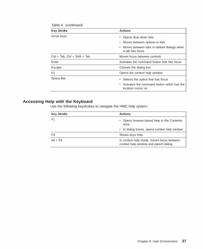
Table 4. (continued)
Key Stroke Actions
Arrow keys v Opens drop down lists
v Moves between options in lists
v Moves between tabs in tabbed dialogs whena tab has focus
Ctrl + Tab, Ctrl + Shift + Tab Moves focus between controls
Enter Activates the command button that has focus
Escape Cancels the dialog box
F1 Opens the context help window
Space Bar v Selects the option that has focus
v Activates the command button which has thelocation cursor on
Accessing Help with the KeyboardUse the following keystrokes to navigate the HMC help system:
Key Stroke Actions
F1 v Opens browser-based help to the ContentsArea
v In dialog boxes, opens context help window
F9 Shows keys help.
Alt + F6 In context help mode, moves focus betweencontext help window and parent dialog.
Chapter 6. User Environment 37

38 IBM Hardware Management Console for pSeries Installation and Operations Guide
Chapter 7. System Configuration
This chapter discusses the System Configuration application, which allows you to dothe following:
v Set the console’s date and time
v Enter and check HMC network information
v View console events
v Schedule routine backups
v Enable and disable remote commands
v Configure serial adapters
v Enable remote virtual terminal connections
v Change the HMC interface language
For more information about the System Configuration application group, read thefollowing section.
Setting and Viewing the Console Date and TimeAny user role can view the console date and time. To update the console date andtime, you must be a member of one of the following roles:
v Advanced Operator
v System Administrator
v Service Representative
v Operator
v Viewer
The battery-operated clock keeps time and date for the HMC. You might need to set theconsole date and time under the following circumstances:
v If the battery is replaced in the HMC
v If your system is physically moved to a different time zone
To customize your console date and time, do the following:
1. In the Navigation area, click the HMC Maintenance icon.
2. In the Contents area, double-click the System Configuration icon.
3. In the Contents area, click Customize Console Date / Time .
4. To change the month, click on the month shown in the Date field. Similarly, click theday or year shown in the Date field to change those values.
5. Click on the hour, minute or second shown in the Time field to change the values.To update this input field to the currently set time, press the Refresh button.
6. From the list, select the region and city closest to your location, and click OK.
39
If you click OK and the new time setting does not show in the lower right of the HMCinterface, log out and then log back in again. For more information about logging out ofthe HMC, see “Shutting Down, Rebooting and Logging Out of the HMC” on page 29.
Viewing Console EventsTo see a log of recent HMC activity, you can view console events. Each event has anassociated time stamp. The following is a sample of the events recorded:
v When a partition was activated
v When a system was powered on
v When a partition was shut down
v Results of a scheduled operation
To view console events, you must be a member of one of the following roles:
v System Administrator
v Advanced Operator
v Service Representative
v Viewer
To view console events, do the following:
1. In the Navigation area, click the HMC Maintenance icon.
2. In the Contents area, double-click the System Configuration icon.
3. In the Contents area, select View Console Events .
Customizing Network SettingsWhile the HMC conducts most of its management function through the direct serialconnections to the managed systems, connecting the HMC to your network providesyou with additional remote management capabilities. It also significantly enhancesservice and maintenance for partitioned systems.
Enabling the HMC network connection allows you to take advantage of the followingHMC capabilities:
v Remote Management : You can access the HMC user interface remotely from aWeb-based System Manager graphical user interface client. Both the Web-basedSystem Manager client and server are provided with the AIX base operating systemcan be installed in any AIX operating system. The client is also available in astandalone version that can be installed on a number of platforms. To manage asystem remotely, you can start the client on a remote system, enter the HMC hostname or IP address, and provide a valid HMC user ID and password. After youcomplete these steps, the HMC user interface options display in the user interface,just like they would on the HMC itself.
The HMC also provides you with some basic command line functions for managingsystems and partitions. With a network connection, you can connect to the HMC and
40 IBM Hardware Management Console for pSeries Installation and Operations Guide
issue these command functions remotely, either manually or as part of an automatedscript. For more information about the high-level command line, see Chapter 20,“Using the Command Line” on page 153.
v Service Functions : To configure your network to allow network connections betweenthe HMC and the partitions in the managed systems, plan to include networkadapters in each partition. While you need only a single network adapter in apartition to handle both management functions and general-purpose networking, youcan also use separate adapters if you want to keep these functions separate, or youcan put them on separate networks.
If the network connections are available:
– The partitions automatically forward hardware service events to the HMC forcollection in the Service Focal Point and for automatic dispatch of service throughService Agent (if enabled). Without these connections, service events are reportedand logged only within the individual partitions that observe them, which can delayreporting and fixing the problem.
– You can use the Inventory Scout application to collect hardware and microcodeinformation from the partitions to the HMC, to build a complete picture of thehardware inventory in a partitioned system. The Inventory Scout application thensends this hardware configuration information to IBM to assist in accuratehardware-upgrade planning. Inventory Scout also enables you to check foravailable updates to the versions of system firmware and adapter microcode thatare currently installed in your systems and partitions.
Using Network Adapters to Communicate with PartitionsAfter a partition has been started, it uses the network adapter to communicate with theHMC. Both the HMC and the partition must be configured so that they can use thenetwork adapters to communicate with each other. The AIX partition must be configuredto identify the HMC (or HMCs) on the network. It is recommended that the network beconfigured using a Domain Name Service (DNS) server and each partition be identifiedusing a fully qualified host name. This identification ensures uniqueness of all thepartitions and the HMC in the network. Fully qualified host names cannot be more than100 bytes in length.
The HMC and partitions can also be configured using a ″short″ host name where thedomain name is not defined. This is typically done in a private or test network. If theHMC is defined using a ″short″ host name, you must perform extra networkconfiguration steps to ensure that the partitions and the HMC communicate correctly.For information about modifying the HMC host name on the partitions, see the AIX 5LVersion 5.2 AIX Installation in a Partitioned Environment guide, order numberSC23-4382.
On the HMC, in order to communicate with a partition that is not identified on thenetwork by a fully qualified host name or if DNS is not being used, the host name of thepartition must be entered in the network settings of the HMC. If you use short hostnames rather than fully qualified host names, make sure that those host names areunique and that the mappings to IP addresses are specified correctly. The HMCprovides an interface for updating the /etc/hosts file. For instructions on addingpartitions to the HMC /etc/hosts file, see “Setting Host Names” on page 43.
Chapter 7. System Configuration 41
The HMC can communicate to partitions that use DNS, fully qualified host names, andshort host names. The following examples illustrate possible situations:
v If the partition is specified using a fully qualified host name (for example:host123.mydomain.mycompany.com), the HMC must enable the use of a DNS server ormust specify the fully qualified host name in the local /etc/hosts file. For instructionson adding partition names to the HMC etc/hosts file, see “Setting Host Names” onpage 43.
v If the partition is specified using a short host name (for example: host123), the HMCmust specify the short host name in the local /etc/hosts file and ensure that theshort host name is located before the fully qualified host name, if the fully qualifiedhost name is also specified in the /etc/hosts file. For instructions on adding partitionnames to the HMC /etc/hosts file, see “Setting Host Names” on page 43.
Note: Changes made to your HMC’s network settings do not take effect until youreboot the HMC.
To customize network settings, you must be a member of one of the following roles:
v Advanced Operator
v System Administrator
v Service Representative
Setting the IP AddressTo customize your HMC’s IP address, do the following:
1. In the Navigation area, click the HMC Maintenance icon.
2. In the Contents area, double-click the System Configuration icon.
3. In the Contents area, click Customize Network Settings . The Customize NetworkSettings window displays.
4. Click the IP Address tab.
5. Type TCP/IP and gateway information as appropriate. For questions about yournetwork and how it is configured, see your network administrator.
6. Click OK if you are finished customizing the network.
Note: Changes made to your HMC’s network settings do not take effect until youreboot the HMC.
Setting Domain NamesTo enable your HMC and managed system for service, you must change the defaultdomain names and enter your own.
To set a domain name, do the following:
1. In the Navigation area, click the HMC Maintenance icon.
2. In the Contents area, double-click the System Configuration icon.
3. In the Contents area, click Customize Network Settings . The Customize NetworkSettings window displays.
4. Click the Name Services tab.
42 IBM Hardware Management Console for pSeries Installation and Operations Guide
5. The system displays the default domain name as localdomain. Replace this namewith your network information as appropriate.
Note: Do not assign the localhost.localdomain with an IP address other than theloopback 127.0.0.1.
For questions about your network and how it is configured, see your networkadministrator.
6. Click OK.
Setting Host NamesThe /etc/hosts file on your HMC’s hard drive stores all host name information. Whetheryou are using DNS or not, you must add the HMC host name using the processdescribed below. If you are not using DNS, you must also add all host names (for eachLPAR and HMC) to this file using the following procedure.
In addition, you must also update the local /etc/hosts files in each LPAR. For moreinformation about updating files, refer to the documentation provided with your operatingsystem.
To set a host name in the /etc/hosts file, do the following:
1. In the Navigation area, click the HMC Maintenance icon.
2. In the Contents area, double-click the System Configuration icon.
3. In the Contents area, click Customize Network Settings . The Customize NetworkSettings window displays.
4. Click the Host tab.
5. Enter your host name information as appropriate.
6. Click OK.
If you change the local host name, you must reboot the HMC for changes to take effect.For more information about rebooting the HMC, see “Shutting Down, Rebooting andLogging Out of the HMC” on page 29.
For more information about setting host names, see the AIX 5L Version 5.2: AIXInstallation in a Partitioned Environment guide, order number SC23-4382.
Adding and Changing IP Addresses and Host NamesYou can add to and change the /etc/hosts file yourself by clicking on the Hosts tab.This window allows you to add any IP address or host names that you want to store inthe /etc/hosts file.
If you need to completely reinstall your partition (which includes setting a new hostname) or if you switch host names between partitions, you must perform the stepslisted in “Changing a Partition Host Name Manually” on page 233 for each affectedpartition.
Chapter 7. System Configuration 43
To add or change a host name in the /etc/hosts file, do the following:
1. In the Navigation area, click the HMC Maintenance icon.
2. In the Contents area, double-click the System Configuration icon.
3. In the Contents area, click Customize Network Settings . The Customize NetworkSettings window displays.
4. Click the Hosts tab.
5. Click New or Change .
6. The Host Entries window opens. In the first field, type the IP address you want toadd or change.
7. In the second field, type the host name or names you want to associate with the IPaddress you typed in the first field. If you enter multiple host names, separate themby spaces and list the primary host name first. Enter multiple host names when youwant to identify a machine by both its fully qualified host name and its short hostname. For example, if your domain is mycompany.com, then for some IP address youmight enter myname.mycompany.com somename.
8. Click OK.
The /etc/hosts file is updated with your new information.
Setting Routing InformationYou can add, change, or delete routing information.
To set routing information, do the following:
1. In the Navigation area, click the HMC Maintenance icon.
2. In the Contents area, double-click the System Configuration icon.
3. In the Contents area, click Customize Network Settings . The Customize NetworkSettings window displays.
4. Click the Routing tab.
5. Select New, Change , or Delete .
6. Type the gateway information in the fields as appropriate. For questions about yournetwork and how it is configured, see your network administrator.
7. Click OK.
Setting Device AttributesYou can use your HMC to select speed and duplex modes for your Ethernet adapters.
To set device attributes, do the following:
1. In the Navigation area, click the HMC Maintenance icon.
2. In the Contents area, double-click the System Configuration icon.
3. In the Contents area, click Customize Network Settings . The Customize NetworkSettings window displays.
4. Click the Device Attributes tab.
44 IBM Hardware Management Console for pSeries Installation and Operations Guide

5. Select the speed and duplex mode for your adapter. For more information aboutyour adapter’s speed and mode, read the documentation that was provided withyour adapter.
6. Click OK.
Testing Network ConnectivityThis option enables you to verify that you are properly connected to the network.
To test network connectivity, you must be a member of one of the following roles:
v Advanced Operator
v System Administrator
v Service Representative
You can test the network connection between the HMC and other hosts by using a pingutility. To test network connectivity, do the following:
1. In the Navigation area, click the HMC Maintenance icon.
2. In the Contents area, double-click the System Configuration icon.
3. In the Contents area, click Test Network Connectivity .
4. Type the host name or IP address of the system to which you are attempting toconnect.
5. Click OK.
To test the connectivity of a partition to your HMC (for example, using the pingcommand), refer to the documentation provided with your partition’s operating system.
Scheduling BackupsThis option enables you to schedule the time and dates for backing up critical consoleinformation. When you schedule a backup operation, the information is saved on aformatted DVD-RAM disk on your HMC. Each time this data is saved, old data isreplaced with the more recent data. If you do not want older information overwritten,insert a new DVD-RAM disk in the HMC’s drive each time you perform a backup.
For more information about critical console data, see “Backing up Critical Console Data”on page 133.
To schedule a backup of console data, you must be a member of one of the followingroles:
v Advanced Operator
v System Administrator
Chapter 7. System Configuration 45
Scheduling a Backup OperationYou can schedule a backup to DVD to occur once, or you can set up a repeatedschedule. You must provide the time and date that you want the operation to occur. Ifthe operation is scheduled to repeat, you must select how you want this backup torepeat (daily, weekly, or monthly).
Note: Only the most-recent backup image is stored at any time on the DVD.
To schedule a backup operation, do the following:
1. In the Navigation area, click the HMC Maintenance icon.
2. In the Contents area, double-click the System Configuration icon.
3. In the Contents area, click Scheduled Operations .
4. In the menu, click Options .
5. Select New.
6. In the appropriate fields, enter the time and date that you want this backup to occur.
7. If you want this scheduled operation to repeat, click the Repeat tab and enter theintervals at which you want the backup to repeat. You can schedule backupoperations to repeat at monthly, weekly, daily, or hourly intervals. If you select Dailyintervals, you can select the individual day of the week you want the backup tooccur. If you want to repeat a scheduled operation daily or hourly, you can alsospecify the days of the week on which you want this operation to occur.
8. Click OK when you are finished setting the backup time and date.
After you have defined a scheduled backup operation, a description of the operationdisplays in the Scheduled Operations window.
Reviewing an Existing Scheduled OperationYou can use the HMC to review an existing scheduled operation that you have created.
To review an existing operation, you must be a member of one of the following roles:
v Advanced Operator
v System Administrator
To review an operation you have already created, do the following:
1. In the Navigation area, click the HMC Maintenance icon.
2. In the Contents area, double-click the System Configuration icon.
3. In the Contents area, click Scheduled Operations from the menu to display a list ofscheduled operations.
Filtering Your ViewYou can view the duration of the backup tasks you scheduled and filter the tasks youwant to view.
To modify your view, you must be a member of one of the following roles:
v Advanced Operator
46 IBM Hardware Management Console for pSeries Installation and Operations Guide
v System Administrator
To view the time range of a scheduled backup, do the following:
1. In the Navigation area, click the HMC Maintenance icon.
2. In the Contents area, double-click the System Configuration icon.
3. In the Contents area, click Scheduled Operations from the menu to display a list ofscheduled operations.
4. Select the operation you want to view.
5. From the menu, select View .
6. Select New Time Range . The Change Time Range window opens.
7. After filtering the time range information you want to view, click OK.
Enabling and Disabling Remote CommandsThis option provides the ability to run commands remotely through the rexec commandor the ssh command.
To install ssh software on PC clients, type the following web address:
http:// HMC System Name /remote_client_security.html
This page provides links to download the PC and Linux security package installed onthe HMC. By default, security is installed and configured; however, the HMC systemadministrator can uninstall the Remote Client Security package. If the HMCadministrator uninstalls the Remote Client Security Package, an error message displaysstating that the Security package needs to be installed. The US strong encryption isalso installed by default, and can also be uninstalled by the HMC system administrator.For more information about the PC Client, see Chapter 8, “Installing and Using theRemote Client” on page 53. For more information about configuring your HMC forsecurity, see Chapter 9, “System Manager Security” on page 59.
On an AIX system, the software to install the Security package is located on theExpansion Pack. The Security installation image operates for both the AIX Client andthe Remote Client; there are no separate installation images. To download the imagesto the Remote Client, the AIX system must also have IHS (IBM HTTP Server) installedand configured. Type the following Web address:
http:// HMC System Name /remote_client_security.html
This page provides links to download the PC and Linux Security package installed onthe system (US or Export).
To enable or disable remote commands, you must be a member of one of the followingroles:
v Advanced Operator
v System Administrator
v Service Representative
Chapter 7. System Configuration 47
To enable or disable remote commands, do the following:
1. In the Navigation area, click the HMC Maintenance icon.
2. In the Contents area, double-click the System Configuration icon.
3. In the Contents area, click Enable / Disable Remote Command Execution .
4. Select the appropriate box.
5. Click OK.
Configuring a Serial AdapterYou can use your HMC to configure adapters that are installed in your HMC.
Configuring Serial AdaptersTo configure serial adapters, do the following:
1. In the Navigation area, click the HMC Maintenance icon.
2. In the Contents area, double-click the System Configuration icon.
3. In the Contents area, click Configure Serial Adapter .
4. The Working window opens. Type 1 to select Configure Serial Adapter(s)
5. The configuration utility guides you through a series of questions. For an 8-portadapter you must answer the following questions with the following answers:
a. Question: How many boards would you like to install? Answer: Type the totalnumber of 8 and/or 128 Port ASYNC adapters in the system.
b. Question: Board #1. What type of board is this? ( L for list) Answer: Use boardtype 15
c. Question: Do you want to set Altpin on this board? ( y or n ) Answer: No
If two 8-port adapters are installed in the system, the HMC asks the followingquestions:
a. Question: Board #2. What type of board is this? ( L for list) Answer: Use boardtype 15
b. Question: Do you want to set Altpin on this board? ( y or n ) Answer: No
For a 128–port adapter, you must answer the following questions with the followinganswers:
a. Question: How many boards would you like to install? Answer: Type the totalnumber of 8 and/or 128 Port ASYNC adapters are installed in the HMC PC.
b. Question: Board #1. What type of board is this? ( L for list) Answer: Use boardtype 16 (IBM 128-Port ASYNC PCI)
c. Question: How many ports does this digiBoard have? Possible values:
1) 8
2) 16
3) 24
4) 32
5) 40
48 IBM Hardware Management Console for pSeries Installation and Operations Guide

6) 48
7) 56
8) 64
9) 72
10) 80
11) 88
12) 96
13) 104
14) 112
15) 120
16) 128
d. Board #1 How many ports? (1–16) Answer: Count the total number of EnhancedRANs you are attaching to the 128-Port ASYNC adapter and multiply by two.For example: 2 (RANs) multiplied by 2 equals 4. Type the selection number 4),for 32 in this example, at the prompt.
e. Question: Do you want to set Altpin on this board? ( y or n ) Answer: No
If two 128-Port ASYNC adapters are installed in the system, the utility repeats theprevious sequence of questions for each. The configuration utility guides youthrough a series of questions.
Note: The term C/CON is synonymous with Enhanced RAN or RAN
a. Question: How many C/X cards do you have? Answer: Type the total number of128 Port ASYNC adapters installed in the HMC PC.
b. Question: How many C/CONs (RANs) are connected to card 1 line 1? Answer:Type the total number of RANs on line 1. For this example, two concentrators(RANs) are connected to line 1.
c. Question: What type of wiring scheme are you going to use for card 1, line 1?
A) 8 Wire DirectB) 4 Wire DirectC) RS422 SyncD) RS232 Sync
Answer: A
d. Enter the type of communication mode to use on line 1. (Type L for a list) [14]Answer: 14
e. Question: How many ports does this C/CON (RAN) support? (conc #1)
Note: The maximum number of ports here is 16. [16]Answer: 16
f. Question: How many C/CONs (RANs) are connected to card 1, line 2? Answer:Enter the number of RANs connected to line 2.
The HMC is configured to load the adapter device driver upon reboot. Reboot yourHMC.
Chapter 7. System Configuration 49
Configuring RS422 Ports on an 8–Port AdapterThis task allows you to switch the port from RS232 to RS422. Use this task for portsthat are connected to a frame’s power supply.
To configure RS422 ports on an 8-port adapter connected to the HMC, do the following:
1. In the Navigation area, click the HMC Maintenance icon.
2. In the Contents area, double-click the System Configuration icon.
3. In the Contents area, click Configure Serial Adapter .
4. The Working window opens. Type 2 to select Configure RS422 ports on an8-port Adapter .
5. From the menu, select the 8 port adapter you want to configure.
6. From the menu, select the port change.
Enabling Remote Virtual Terminal ConnectionsRemote virtual terminal connections are disabled by default. This section describes howto enable remote virtual terminal connections.
To enable remote virtual terminal connections, you must be a member of the SystemAdministrator role.
To enable remote virtual terminal connections, do the following:
1. In the Navigation area, click the HMC Maintenance icon.
2. In the Contents area, double-click the System Configuration icon.
3. In the Contents area, click Enable/Disable Remote Virtual Terminal Connections .The Enable Remote Virtual Terminal window displays.
4. Click the Enable remote virtual terminal connections box.
5. Click OK.
Changing the HMC Interface LanguageYou can change the language of your HMC interface by:
v Powering on the HMC
OR
v Using the Change Current Locale application
When you power on the HMC, the HMC automatically prompts you to change thelocale. The locale is the language you want your HMC to display. If you do not respond,the HMC continues to power on with the last locale used.
Any user role can change the HMC’s interface language.
To change your HMC’s interface language when you power on the HMC, do thefollowing:
50 IBM Hardware Management Console for pSeries Installation and Operations Guide
1. Power on the HMC.
2. When you are prompted to change the locale, type the number 2 to select ChangeLocale. The Locale Selection window opens.
3. Select the locale you want to display from the list.
4. Click OK.
When the HMC completes the power on process, it displays the language you selected.
To change your HMC’s interface language by using the System Configurationapplication, do the following:
1. In the Navigation area, click the HMC Maintenance icon.
2. In the Contents area, double-click the System Configuration icon.
3. In the Contents area, click Change Current Locale .
4. A window opens. Select the locale you want from the list.
5. Click OK.
6. Log out of the HMC interface and then log back in to the HMC interface. For moreinformation about logging out and logging in, see “Shutting Down, Rebooting andLogging Out of the HMC” on page 29.
Chapter 7. System Configuration 51

52 IBM Hardware Management Console for pSeries Installation and Operations Guide
Chapter 8. Installing and Using the Remote Client
You can access your HMC remotely by installing and configuring the remote client onyour PC.
Note: Remote management does not allow you to do the following:
v Configure System Manager Security for certificate authority or view Overviewand Status information
v Determine the level of HMC code
v Reboot the HMC interface
This chapter discusses how to install the remote client and Remote Client Security.
Installation Requirements to Support Remote Client and Remote Client SecurityIf you are going to use a PC to run the Remote Client, your computer must have thefollowing:
v Either the Microsoft Windows (supported versions include Windows NT, Windows2000, or Windows XP) or the Linux (supported versions include Red Hat 7.2 or RedHat 7.3) operating system
v 150 MB of free disk space on the default drive for temporary use during theinstallation procedure
v 150 MB of free disk space on the drive that you plan to use to install the RemoteClient
v PC processor speed of at least 800 MHz
v A minimum of 256 MB of memory (512 MB of memory is recommended)
Installing the Remote Client on a Microsoft Windows SystemTo install the Remote Client on a Microsoft Windows system, do the following:
1. Uninstall any previous version of Web-based System Manager Remote Client. Formore information, see “Uninstalling the Remote Client from a Microsoft WindowsSystem” on page 54.
2. Type the following address in your machine’s Web browser:
hostname/remote_client.html
where hostname is the name of the HMC.
3. Click the Windows link that appears on the Web page. This will download thesetup.exe file to your machine.
4. Run the setup.exe file to begin the installation process.
5. When the Remote Client Installer panel displays, click Next to continue.
6. To install using the default location, click Next . Otherwise, type the desired locationand click Next .
53

7. A confirmation panel displays, showing you the installation location, the packagebeing installed, and the approximate size of the installation package. Click Next tostart the installation. If any of the information shown is incorrect, click Back to makecorrections.
8. A status panel displays a message that says the installation completed successfullyor error messages if errors occurred during the installation. Click Finish to close thepanel.
Uninstalling the Remote Client from a Microsoft Windows SystemTo uninstall the Remote Client from a Microsoft Windows system, do the following:
1. From the taskbar, select Start --> Settings --> Control Panel .
2. In the Control Panel , double-click the Add/Remove Programs icon.
3. Select Web-Based System Manager Remote Client from the list of programs onthe Install/Uninstall tab, then click Add/Remove to start the Uninstall wizard.
Note: Earlier versions of Remote Client may display as Web-based SystemManager PC Client.
4. Click Next in the initial panel.
5. Click Next in the Confirmation panel to uninstall Remote Client.
6. A status panel displays, showing either that the installation completed successfully,or any messages if errors occurred during the installation. Click Finish to close thepanel.
Installing the Remote Client on a Linux SystemTo install the Remote Client on a Linux system, do the following:
1. Uninstall any previous version of Linux Client on your machine. For moreinformation, see “Uninstalling Remote Client from a Linux System” on page 55.
2. Type the following address in your machine’s Web browser:
hostname/remote_client.html
where hostname is the name of the HMC.
3. Click the Linux link on the Web page to download the wsmlinuxclient.exe file toyour machine.
4. Run the wsmlinuxclient.exe file to begin the installation process. If the file will notrun, modify the permissions on the file so that you have execute permissions. At acommand prompt, type the following:
chmod 755 wsmlinuxclient.exe
5. When the Remote Client Installer panel displays, click Next to continue.
6. To install using the default location, click Next . Otherwise, type the desired locationand click Next .
54 IBM Hardware Management Console for pSeries Installation and Operations Guide
7. A confirmation panel displays, showing you the installation location, the packagebeing installed, and the approximate size of the installation package. Click Next tostart the installation. If any of the information shown is incorrect, click Back to makecorrections.
8. A status panel displays a message that says the installation completed successfully,or error messages if errors occurred during the installation. Click Finish to close thepanel.
Note: If changes do not take effect immediately, either log out of your currentsession and log in again, or source your . /etc/profile file.
Uninstalling Remote Client from a Linux SystemTo uninstall the Remote Client from a Linux system, run the following command:
installdir/_uninst/uninstall
where installdir is the name of the directory in which your Remote Client resides.
Installing the Remote Client SecurityThis section describes how to install the Remote Client Security.
Installing Remote Client Security on the Microsoft Windows SystemTo install Remote Client Security on the Microsoft Windows system, do the following:
1. Type the following Web address in your machine’s Web browser:
hostname/remote_client_security.html
where hostname is the name of the HMC.
2. Click the Windows link on the Web page to download the setupsec.exe file to yourmachine.
3. Run the setupsec.exe file to begin the installation process.
4. When the Remote Client Security Installer panel displays, click Next to continue.
5. To install using the default location, click Next . Otherwise, type the desired locationand click Next .
Note: Be sure that the location you select in this step is the same location youselected in “Installing the Remote Client on a Microsoft Windows System” onpage 53.
6. A confirmation panel displays, showing you the installation location, the packagebeing installed, and the approximate size of the installation package. Click Next tostart the installation. If any of the information shown is incorrect, click Back to makecorrections.
7. A status panel displays a message that says the installation completed successfully,or error messages if an error occurred during the installation. Click Finish to closethe panel.
Chapter 8. Installing and Using the Remote Client 55
Uninstalling Remote Client Security from a Microsoft Windows SystemTo uninstall the Remote Client from a Microsoft Windows system, do the following:
1. From the taskbar, select Start --> Settings --> Control Panel .
2. In the Control Panel , double-click the Add/Remove Programs icon.
3. Select Remote Client Security from the list of programs on the Install/Uninstalltab, then click Add/Remove to start the Uninstall wizard.
Note: Earlier versions of Remote Client Security may display as Web-basedSystem Manager PC Client Security.
4. Click Next in the initial panel.
5. Click Next in the Confirmation panel to uninstall Remote Client Security.
6. A status panel displays, showing either that the installation completed successfully,or any messages if errors occurred during the installation. Click Finish to close thepanel.
Installing the Remote Client Security on a Linux SystemTo install the Remote Client Security on a Linux system, do the following:
1. Uninstall any previous version of Remote Client Security on your machine. For moreinformation, see “Uninstalling Remote Client Security from a Linux System” onpage 57.
2. Type the following address in your machine’s Web browser:
hostname/remote_client_security.html
where hostname is the name of the HMC.
3. Click the Linux link on the Web page to download the setupsecl.exe file to yourmachine.
4. Run the setupsecl.exe file to begin the installation process. If the file will not run,modify the permissions on the file so that you have execute permissions. At acommand prompt, type the following:
chmod 755 setupsecl.exe
5. When the Remote Client Security Installer panel displays, click Next to continue.
6. To install using the default location, click Next . Otherwise, type the desired locationand click Next .
Note: Be sure the location you select in this step is the same location you selectedin “Installing the Remote Client on a Linux System” on page 54.
7. A confirmation panel displays, showing you the installation location, the packagebeing installed, and the approximate size of the installation package. Click Next tostart the installation. If any of the information shown is incorrect, click Back to makecorrections.
8. A status panel displays a message that says the installation completed successfully,or error messages if errors occurred during the installation. Click Finish to close thepanel.
56 IBM Hardware Management Console for pSeries Installation and Operations Guide
Note: If changes do not take effect immediately, either log out of your currentsession and log in again, or source your . /etc/profile file.
Uninstalling Remote Client Security from a Linux SystemTo uninstall the Remote Client from a Linux system, run the following command:
installdir/_uninstssl/uninstallssl
where installdir is the name of the directory in which your Remote Client resides.
Configuring Remote Client SecurityTo establish secure connections in PC Client mode, copy the Certificate Authority’sSM.pubkr public key file to the codebase directory in the location where you installedPC Client.
For more information about copying this key file, see “Distribute the CertificateAuthority’s Public Key to Your Clients” on page 62.
Chapter 8. Installing and Using the Remote Client 57

58 IBM Hardware Management Console for pSeries Installation and Operations Guide
Chapter 9. System Manager Security
System Manager Security ensures that the HMC can operate securely in theclient-server mode. Managed machines are servers and the managed users are clients.Servers and clients communicate over the Secure Sockets Layer (SSL) protocol, whichprovides server authentication, data encryption, and data integrity. Each HMC SystemManager server has its own private key and a certificate of its public key signed by aCertificate Authority (CA) that is trusted by the System Manager clients. The private keyand the server certificate are stored in the server’s private key ring file. Each client musthave a public key ring file that contains the certificate of the trusted CA.
Define one HMC as a Certificate Authority. You will use this HMC to generate keys andcertificates for your HMC servers and client systems. The servers are the HMCs youwant to manage remotely. A unique key must be generated and installed on eachserver. You can generate the keys for all your servers in one action on the CA and thencopy them to diskette, install them at the servers, and configure the servers for secureoperation.
The client systems are the systems from which you want to do remote management.Client systems can be HMCs, AIX, or PC clients. Each client system must have a copyof the CA’s public key ring file in its System Manager codebase directory. You can copythe CA public key ring file to the diskette on the CA and copy it from the diskette toeach client.
Note: You must install a security fileset in order to configure an AIX client correctly.Refer to your AIX documentation for more information.
To use the System Manager Security application, you must be a member of the SystemAdministrator role. To ensure security during configuration, users of this applicationmust be logged in to the HMC locally.
This chapter describes configuration tasks associated with System Manager Security.
Configuring HMC System Manager Servers and Clients for Secure OperationThe following steps are required to configure HMC System Manager servers and clientsfor secure operation.
Configure One HMC as a Certificate Authority
Note: You cannot perform this function using the Remote Client.
Define one HMC as a Certificate Authority (CA) to generate keys and certificates foryour HMC servers and clients.
A Certificate Authority verifies the identities of the HMC servers to ensure securecommunications between clients and servers. To define a system as a CertificateAuthority, you must be logged in as the hscroot user at the machine being defined as
59
the internal Certificate Authority. This procedure defines a system as an internalCertificate Authority for HMC security and creates a public key ring file for theCertificate Authority that you can distribute to all of the clients that access the HMCservers.
To configure a system as a Certificate Authority, do the following:
1. In the Navigation area, click System Manager Security .
2. In the Contents area, select Certificate Authority .
3. In the System Manager Security:Certificate Authority window, select Configure ThisSystem as a Certificate Authority . You can also select Configure... from theCertificate Authority menu.
4. Use the wizard panels to complete the task.
Generate Private Key Ring Files for the HMCs That You Want to ManageRemotely
After you define the internal Certificate Authority, you can use the CA to create theprivate key ring files for the HMCs that you want to manage remotely.
Each HMC server must have its private key and a certificate of its public key signed bya Certificate Authority that is trusted by the HMC clients. The private key and the servercertificate are stored in the server’s private key ring file.
To create private key ring files for your servers, do the following:
1. In the Navigation area, select System Manager Security .
2. In the Contents area, select Certificate Authority .
3. In the System Manager Security:Certificate Authority window, select GenerateServers’ Private Key Ring Files . You can also select Generate Keys... from theCertificate Authority menu.
4. In the Password window, type the certificate authority private key file password.This password was created when the system was configured as the CertificateAuthority.
5. Click OK.
6. In the Generate Server’s Private Key Ring Files window, use the help to guide youthrough completing the task. To view help in the windows, click Help to open theHelp window, then move the cursor over the item for which you want to displayhelp.
7. Click OK when you are finished.
Install the Private Key Ring Files and Configure Your HMC Servers as SecureSystem Manager Servers
After you generate the private key ring files for your HMC servers, you can copy themto a diskette and install them on the servers.
60 IBM Hardware Management Console for pSeries Installation and Operations Guide
Copying Server Private Key Ring Files to DisketteThis procedure copies the servers’ private key ring files to a tar diskette so that you caninstall them on your servers.
To copy the servers’ private key ring files to a diskette, do the following:
1. In the Navigation area, select System Manager Security .
2. In the Contents area, select Certificate Authority .
3. In the System Manager Security:Certificate Authority window, select Copy Servers’Private Key Ring Files to Diskette . You can also select Copy Servers’ Keys...from the Certificate Authority menu.
4. When the Copy Server’s Private Key to Diskette dialog displays, insert a diskette.To view help in the dialog, click Help to open the Help window, then move thecursor over the item for which you want to display help.
5. Click OK to copy the servers’ private key ring files.
Installing the Private Key Ring File on Each ServerThis procedure installs a server’s private key ring file from a tar diskette.
Install the private key ring files from the tar diskette onto each server. Repeat thefollowing steps for each server for which you generated a private key ring file.
To install a server’s private key ring file, do the following:
1. In the Navigation area, select System Manager Security .
2. In the Contents area, select Server Security .
3. In the System Manager Security:Server Security window, select Install the privatekey ring for this server . You can also select Install Key... from the Server Securitymenu.
4. In the Install Private Key Ring File window, select tar diskette as the source for theserver private key ring files. Insert the diskette containing the server’s key into thediskette drive.
5. Click OK.
Use the help to guide you through completing the task. To view help in the dialog, clickHelp to open the Help window, then move the cursor over the item for which you wantto display help.
Configuring a System as an HMC Secure ServerConfigure the system as a secure server. Repeat the following steps for each server onwhich you installed a private key ring file.
To configure a server as a secure server, do the following:
1. In the Navigation area, select System Manager Security .
2. In the Contents area, select Server Security .
3. In the System Manager Security:Server Security window, select Configure thissystem as a secure HMC server . You can also select Configure... from the ServerSecurity menu.
Chapter 9. System Manager Security 61
4. Use the wizard panels to complete the task.
Distribute the Certificate Authority’s Public Key to Your ClientsEach client must have a copy of the Certificate Authority’s public key ring file(SM.pubkr ) installed in its System Manager codebase directory. The remote client andremote client security must be installed on your client systems before you distribute theCA’s public key. For more information about installing the remote client and remoteclient security, see Chapter 8, “Installing and Using the Remote Client” on page 53.
The public key ring file can be copied from the CA to a tar diskette or as a PC DOSfile, then copied from the diskette onto each client.
Copying the Certificate Authority’s Public Key Ring File to Diskette
Note: To copy the certificate authority’s public key ring file to diskette, have aDOS-formatted diskette available for use.
To copy the Certificate Authority’s public key ring file to diskette, do the following on theCA system:
1. In the Navigation area, select System Manager Security .
2. In the Contents area, select Certificate Authority .
3. In the System Manager Security:Certificate Authority window, select Copy thisCertificate Authority’s Public Key Ring File to Diskette . You can also selectCopy out CA Public Key... from the Certificate Authority menu.
4. When the Copy CA Public Key to Diskette window opens, insert a diskette.
5. Select the type of client to which you want the public key ring file to be copied.Selecting HMC or AIX client writes the file to a tar diskette. Selecting PC clientwrites the file to diskette in DOS file format. Use the help to guide you throughcompleting the task. To view help in the dialog, click Help to open the Help window,then move the cursor over the item for which you want to display help.
6. Click OK to copy the public key ring file.
Copying a Certificate Authority’s Public Key Ring File fromDiskette to an HMC ClientAll clients must have a copy of the Certificate Authority’s public key ring file (SM.pubkr )installed in its System Manager codebase directory.
To copy a Certificate Authority’s public key ring file from diskette to an HMC client, dothe following on each HMC that you want to use as a client for remotely managingHMCs:
1. In the Navigation area, select System Manager Security .
2. In the Contents area, select Certificate Authority .
3. In the System Manager Security:Certificate Authority window, select Copy anotherCertificate Authorities Public Key Ring File from diskette . You can also selectCopy in CA Public Key... from the Certificate Authority menu.
4. When the Copy CA Public Key from Diskette window opens, insert the tar diskettethat contains the copied Certificate Authority’s public key ring file.
62 IBM Hardware Management Console for pSeries Installation and Operations Guide
To view help in the dialog, click Help to open the Help window, then move thecursor over the item for which you want to display help.
5. Click OK to copy the public key ring file.
To copy a Certificate Authority’s public key ring file from a tar diskette to an AIX client,use the tar command to extract the SM.pubkr file to the /usr/websm/codebasedirectory.
To copy a Certificate Authority’s public key ring file from diskette to a PC Client, use aDOS copy command to copy the SM.pubkr file into the codebase directory in thelocation where you installed PC Client.
Viewing Configuration PropertiesAfter the security configuration has been completed, you can view the properties of theCertificate Authority (CA) and of any server.
To view CA properties, do the following:
1. In the Navigation area, select your local host.
2. Underneath the local host, click the System Manager Security icon.
3. Click Certificate Authority .
4. Select Properties .
5. Type the password.
Note: This window provides read-only information for the CA.
To view a server’s properties, do the following on the server:
1. In the Navigation area, select your local host.
2. Underneath the local host, click the System Manager Security icon.
3. Click Server Security .
4. Select View properties for this server from the task list.
Note: This window provides read-only information for the server.
Chapter 9. System Manager Security 63
Configure HMC Object Manager SecurityBefore performing this task, you must install the server private key ring file on the HMC.Then you can configure Object Manager Security to switch between plain sockets andSSL protocols.
To configure HMC Object Manager Security, do the following:
1. In the Navigation area, select your local host.
2. Underneath the local host, click the System Manager Security icon.
3. Click Object Manager Security .
4. Select Configure Object Manager Security .
5. Select a socket mode.
6. Click OK.
64 IBM Hardware Management Console for pSeries Installation and Operations Guide
Chapter 10. Inventory Scout Services
This chapter provides information about Inventory Scout Services, a tool that surveysmanaged systems for hardware and software information. Recent releases of AIX andHMC code provide an automatic configuration mechanism and eliminate the need foryou to manually reconfigure Inventory Scout. Depending on the levels of your HMC andpartition software, you may be required to manually configure partitions that you createin order to perform Inventory Scout tasks. Depending on your HMC level you may alsohave to reconfigure Inventory Scout whenever you change partition information.
You can use the HMC to perform the following Inventory Scout Services tasks:
v Inventory Scout Profile Configuration
v Conduct Microcode Survey
v Collect VPD Information
v Restart Inventory Scout Daemon
Perform each of these tasks by entering information into one or more windows.
Configuring the Inventory Scout Services ProfileTo set up Inventory Scout Services for each managed system and partition, you mustbe a member of one of the following roles:
v System Administrator
v Advanced Operator
v Service Representative
To accurately configure Inventory Scout, activate all the partitions in the managedsystem.
To configure a partition for Inventory Scout, do the following:
1. In the Navigation area, click the Service Applications icon.
2. In the Contents area, double-click the Inventory Scout Services icon.
3. In the Contents area, click Inventory Scout Profile Configuration . The InventoryScout Configuration Assistant window opens.
4. Select the managed system you want to configure and click Next .
5. A list of partitions, along with each partition’s configuration status, displays. Systemsthat have status of automatically configured do not require configuration.Partitions listed as not configured need to be manually configured. For moreinformation about manually configuring Inventory Scout, see “Manually ConfiguringInventory Scout Services” on page 66.
65
Manually Configuring Inventory Scout ServicesThis wizard helps you set up Inventory Scout Services for each system managed by theHMC, and for each logical partition running an instance of AIX. All partitions must beeither auto configured or manually configured in order to conduct microcode surveys orcollect VPD.
Notes:
v The default listening port for Inventory Scout Services is 808.
v If a system has been powered on using the Full System Partition power-on option,configure the Full System Partition to use Inventory Scout Services.
v You must also do the following for each partition:
– Set up a password for the inventory scout user ID.
– Set up the operating system to automatically start the Inventory scout daemonwhenever the partition is rebooted.
For more information about configuring your operating system, refer to thedocumentation supplied with your operating system.
To manually configure Inventory Scout Services for each managed system and partition,do the following:
1. In the Navigation area, click the Service Applications icon.
2. In the Contents area, double-click the Inventory Scout Services icon.
3. In the Contents area, click Inventory Scout Profile Configuration . The InventoryScout Configuration Assistant window opens.
4. From the list, select a managed system for which you want to configure InventoryScout.
5. Click Next .
6. The partitions are displayed, along with their configuration status. From the list,select the partition you want to configure.
7. Click Next . The next window identifies the selected partition.
8. Type the following:
v Partition password (this password is the invscout password for the AIX partition.It must first be set by the AIX administrator on each partition - for example, byusing the passwd invscout command.)
v Inventory Scout listening port (default is 808).
v IP address of the AIX partition
Note: If the IP address is not automatically detected by the HMC, Service FocalPoint is not configured properly. For more information about configuringService Focal Point, see “Service Focal Point Settings” on page 146.
9. To configure additional partitions, you can click either the Next or Previous buttons.
OR
Click Done to complete the partition configuration and return to the previous panel.
66 IBM Hardware Management Console for pSeries Installation and Operations Guide
Conducting Microcode SurveysThis process allows you to collect microcode data for the managed system into a file.
Note: Microcode surveys require that all partitions be active to ensure that the surveydata is accurate.
To conduct microcode surveys, you must be a member of one of the following roles:
v System Administrator
v Advanced Operator
v Service Representative
To conduct microcode surveys, do the following:
1. In the Navigation area, click the Service Applications icon.
2. In the Contents area, double-click the Inventory Scout Services icon.
3. In the Contents area, click Conduct Microcode Survey .
4. From the list, select the name of the managed system for which you want to collectthe microcode data.
5. Click Next .
6. The wizard requests confirmation of the managed system, and then prompts you toinsert a blank, DOS-formatted diskette into the HMC diskette drive. Put the diskettein the drive and then click Finish .
7. When you complete this task, Inventory Scout collects the microcode data for thespecified managed system into a file. This file is then copied to the diskette in thespecified drive.
Collecting Vital Product Data InformationUse this option to collect the Vital Product Data (VPD) for the specified managedsystem into a file.
Note: VPD collection requires that all partitions be active to ensure that the survey datais accurate.
To collect the managed system’s VPD, you must be a member of one of the followingroles:
v System Administrator
v Advanced Operator
v Service Representative
To collect the managed system’s VPD, do the following:
1. In the Navigation area, click the Service Applications icon.
2. In the Contents area, double-click the Inventory Scout Services icon.
3. In the Contents area, click Collect VPD information .
Chapter 10. Inventory Scout Services 67
4. From the list, select the name of the managed system for which you want to collectthe VPD.
5. Click Next .
6. The wizard requests confirmation about the managed system, and then prompts youto insert a blank, DOS-formatted diskette into the HMC diskette drive.
7. Click Finish . The file containing the VPD is then copied to the diskette in thespecified drive.
Restarting Inventory Scout ServicesInventory scout has a daemon that can be started to allow you to survey the HMC VPDand microcode remotely. Start this applet if you wish to enable this function. If thedaemon stops running, or if you need to stop and then restart the daemon, use thistask to start the daemon. If the daemon is already running, this task stops the daemon,and then restarts it.
To restart the Inventory Scout daemon, you must be a member of one of the followingroles:
v System Administrator
v Advanced Operator
v Service Representative
v Operator
To restart the Inventory Scout daemon, do the following:
1. In the Navigation area, click the Service Applications icon.
2. In the Contents area, double-click the Inventory Scout Services icon.
3. In the Contents area, click Restart Inventory Scout Daemon .
4. Click Restart .
68 IBM Hardware Management Console for pSeries Installation and Operations Guide
Chapter 11. Using Two HMCs Connected to One Managed System
This chapter describes how to perform operations on two HMCs connected to onemanaged system.
Each system that supports a Hardware Management Console has two serial portconnections, so that you may optionally attach a second HMC to the same system. Thebenefits of using two HMCs are as follows:
v Ensures that access to the HMC management function capabilities are notinterrupted
v Ensures access if the network is down
Working with Two HMCsIn configurations with two HMCs, both HMCs are fully active and accessible at all times,enabling you to perform management tasks from either HMC at any time. There is noprimary or backup designation.
To avoid basic conflicts, mechanisms in the communication interface between HMCsand the managed systems allow an HMC to temporarily take exclusive control of theinterface, effectively locking out the other HMC. Usually this locking is done only for theduration of time it takes to complete an operation, after which the interface is availablefor further commands. HMCs are also automatically notified of any changes that occurin the managed systems, so the results of commands issued by one HMC are visible inthe other. For example, if you select to activate a partition from one HMC, you willobserve the partition going to the Starting and Running states on both HMCs.
The locking between HMCs does not prevent users from running commands that mightseem to be in conflict with each other. For example, if the user on one HMC selects toactivate a partition, and a short time later, a user on the other HMC selects to power offthe system, the system will power off. Effectively, any sequence of commands that youcan do from a single HMC is also permitted when your environment contains redundantHMCs. For this reason, it is important to carefully consider how you want to use thisredundant capability to avoid such conflicts. You might choose to use them in a primaryand backup role, even though the HMCs are not restricted in that way.
The interface locking between two HMCs is automatic, is usually of short duration, andmost console operations wait for the lock to release without requiring user intervention.However, if one HMC experiences a problem while in the middle of an operation, it maybe necessary to manually release the lock. For more information on this task, see“Releasing an HMC Lock on the Managed System” on page 237.
69

Other Considerations for Redundant HMCsBecause authorized users can be defined independently for each HMC, determinewhether the users of one HMC should be authorized on the other. If so, the userauthorization must be set up separately on each HMC.
Because both the HMCs provide Service Focal Point and Service Agent functions,connect a modem and phone line to only one of the HMCs, and enable its ServiceAgent. To prevent redundant service calls enable Service Agent on on only one HMC.
Perform HMC software maintenance separately on each HMC, at separate times, sothat there is no interruption in accessing HMC function. This situation allows one HMCto run at the new fix level, while the other HMC can continue to run at the previous fixlevel. However, the best practice is to move both HMCs to the same fix level as soonas possible.
70 IBM Hardware Management Console for pSeries Installation and Operations Guide
Chapter 12. User Management
This chapter discusses how an HMC system administrator can manage users andassign roles. To use the User Management application, first determine who will use theHMC. Next, you can assign a role to that user to assign appropriate access. Forexample, you can create general users and assign operator roles to these users so thatthey can perform basic HMC tasks.
Note: You must create a user named hscpe so that your software supportrepresentative has access to perform fixes on the HMC code. This user name isreserved for your support representative and is considered a ″hidden″ role. Donot assign the hscpe user name to one of your users. For more informationabout creating users and assigning roles, see “Creating a User” on page 77.
Overview of RolesEach HMC user can be a member of one of six different roles. Each of these rolesallows the user to access different parts of the HMC. The user roles specified by theHMC are as follows:
v System Administrator
v Advanced Operator
v Service Representative
v Operator
v User Administrator
v Viewer
Each role is described as follows:
System AdministratorThe System Administrator acts as the root user, or manager of the HMCsystem. The System Administrator has unrestricted authority to access andmodify most of the HMC system.
Advanced OperatorAn Advanced Operator can perform some partition or system configuration andhas access to some user-management functions.
Service RepresentativeA Service Representative is an employee who is at your location to install orrepair the system.
OperatorAn Operator is responsible for daily system operation.
User AdministratorA User Administrator can perform user-management tasks, but cannot performany other HMC functions.
Viewer A Viewer can view HMC information, but cannot change any configurationinformation.
71
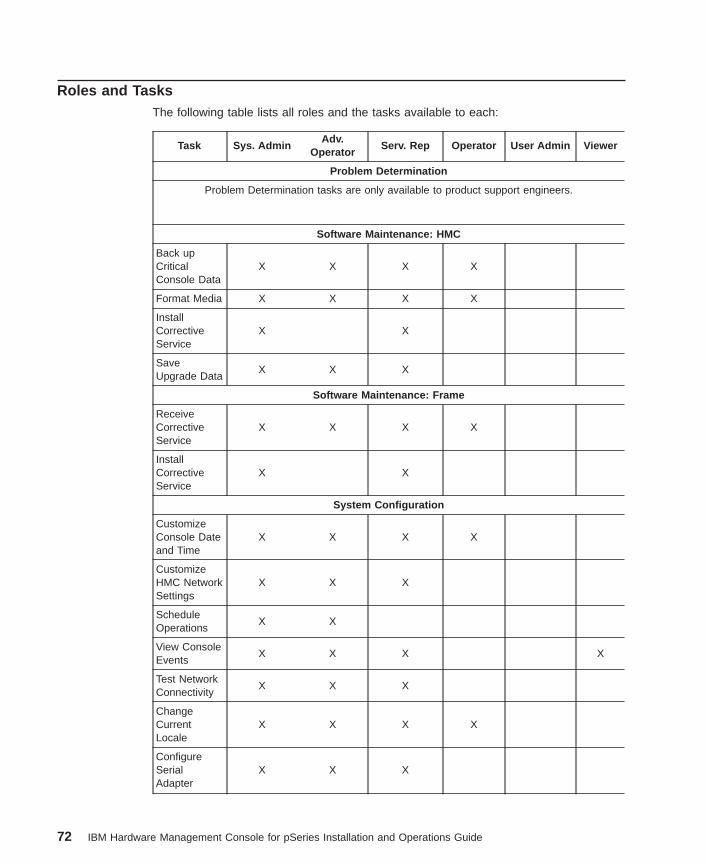
Roles and TasksThe following table lists all roles and the tasks available to each:
Task Sys. AdminAdv.
OperatorServ. Rep Operator User Admin Viewer
Problem Determination
Problem Determination tasks are only available to product support engineers.
Software Maintenance: HMC
Back upCriticalConsole Data
X X X X
Format Media X X X X
InstallCorrectiveService
X X
SaveUpgrade Data
X X X
Software Maintenance: Frame
ReceiveCorrectiveService
X X X X
InstallCorrectiveService
X X
System Configuration
CustomizeConsole Dateand Time
X X X X
CustomizeHMC NetworkSettings
X X X
ScheduleOperations
X X
View ConsoleEvents
X X X X
Test NetworkConnectivity
X X X
ChangeCurrentLocale
X X X X
ConfigureSerialAdapter
X X X
72 IBM Hardware Management Console for pSeries Installation and Operations Guide
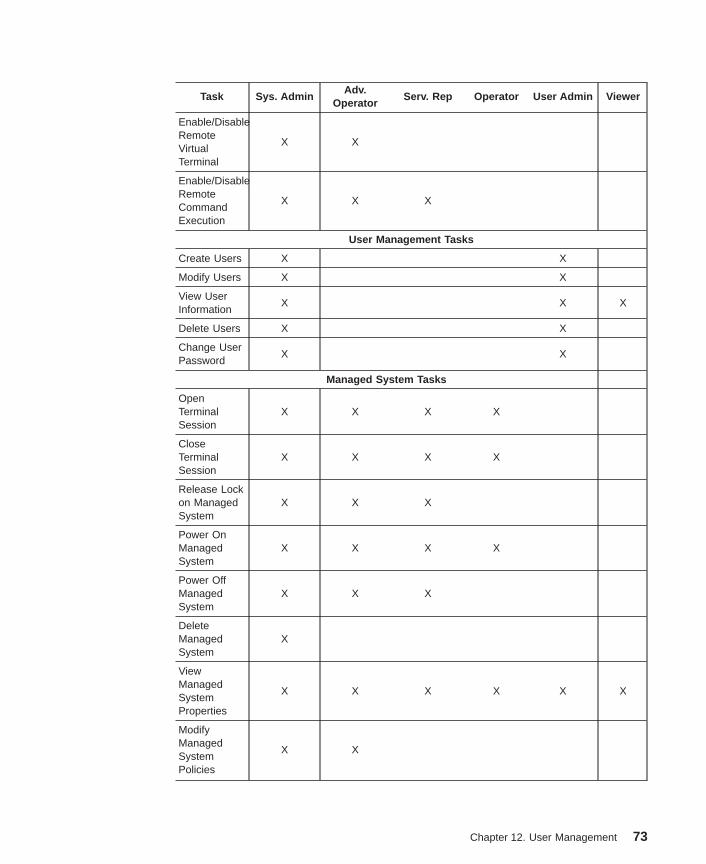
Task Sys. AdminAdv.
OperatorServ. Rep Operator User Admin Viewer
Enable/DisableRemoteVirtualTerminal
X X
Enable/DisableRemoteCommandExecution
X X X
User Management Tasks
Create Users X X
Modify Users X X
View UserInformation
X X X
Delete Users X X
Change UserPassword
X X
Managed System Tasks
OpenTerminalSession
X X X X
CloseTerminalSession
X X X X
Release Lockon ManagedSystem
X X X
Power OnManagedSystem
X X X X
Power OffManagedSystem
X X X
DeleteManagedSystem
X
ViewManagedSystemProperties
X X X X X X
ModifyManagedSystemPolicies
X X
Chapter 12. User Management 73
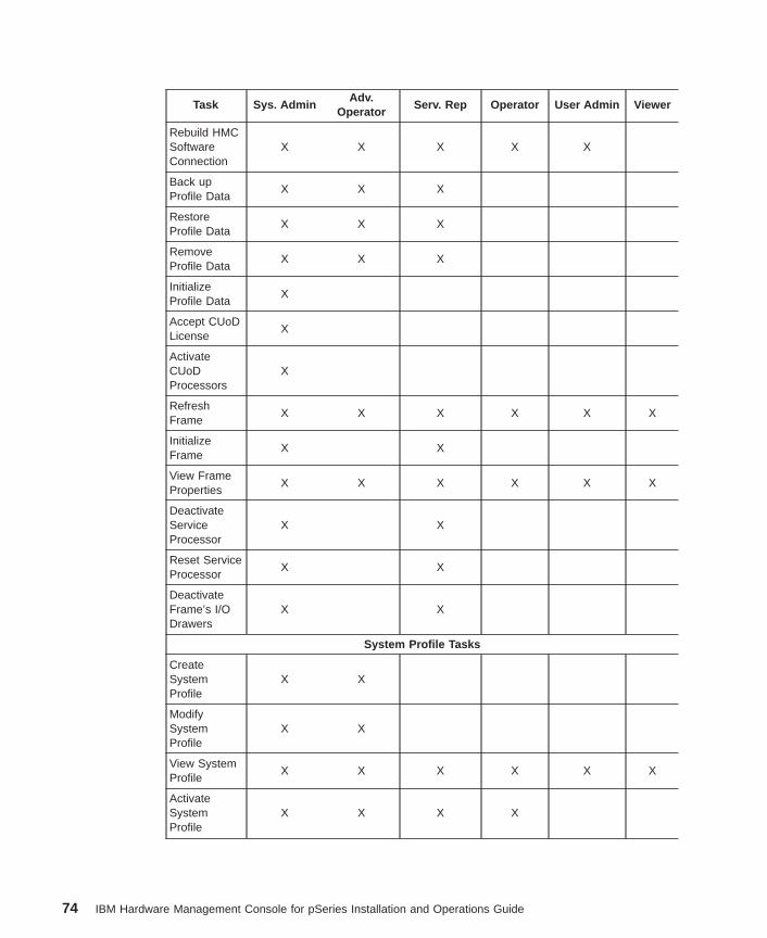
Task Sys. AdminAdv.
OperatorServ. Rep Operator User Admin Viewer
Rebuild HMCSoftwareConnection
X X X X X
Back upProfile Data
X X X
RestoreProfile Data
X X X
RemoveProfile Data
X X X
InitializeProfile Data
X
Accept CUoDLicense
X
ActivateCUoDProcessors
X
RefreshFrame
X X X X X X
InitializeFrame
X X
View FrameProperties
X X X X X X
DeactivateServiceProcessor
X X
Reset ServiceProcessor
X X
DeactivateFrame’s I/ODrawers
X X
System Profile Tasks
CreateSystemProfile
X X
ModifySystemProfile
X X
View SystemProfile
X X X X X X
ActivateSystemProfile
X X X X
74 IBM Hardware Management Console for pSeries Installation and Operations Guide
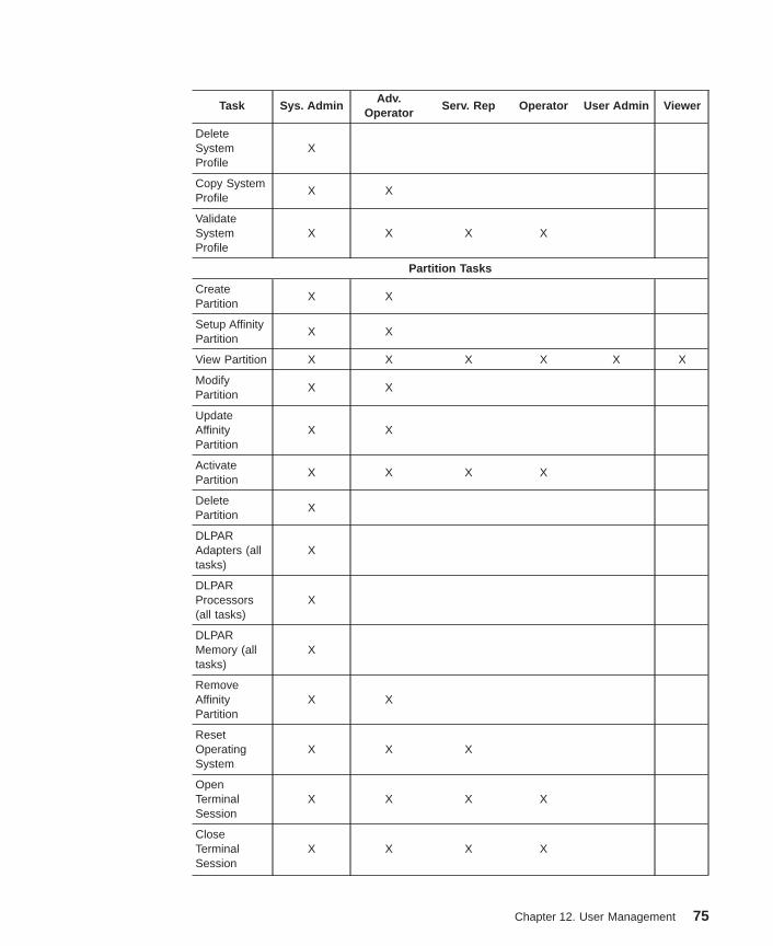
Task Sys. AdminAdv.
OperatorServ. Rep Operator User Admin Viewer
DeleteSystemProfile
X
Copy SystemProfile
X X
ValidateSystemProfile
X X X X
Partition Tasks
CreatePartition
X X
Setup AffinityPartition
X X
View Partition X X X X X X
ModifyPartition
X X
UpdateAffinityPartition
X X
ActivatePartition
X X X X
DeletePartition
X
DLPARAdapters (alltasks)
X
DLPARProcessors(all tasks)
X
DLPARMemory (alltasks)
X
RemoveAffinityPartition
X X
ResetOperatingSystem
X X X
OpenTerminalSession
X X X X
CloseTerminalSession
X X X X
Chapter 12. User Management 75
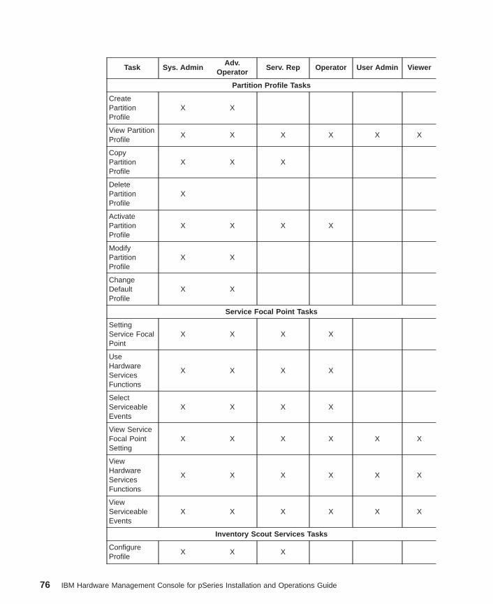
Task Sys. AdminAdv.
OperatorServ. Rep Operator User Admin Viewer
Partition Profile Tasks
CreatePartitionProfile
X X
View PartitionProfile
X X X X X X
CopyPartitionProfile
X X X
DeletePartitionProfile
X
ActivatePartitionProfile
X X X X
ModifyPartitionProfile
X X
ChangeDefaultProfile
X X
Service Focal Point Tasks
SettingService FocalPoint
X X X X
UseHardwareServicesFunctions
X X X X
SelectServiceableEvents
X X X X
View ServiceFocal PointSetting
X X X X X X
ViewHardwareServicesFunctions
X X X X X X
ViewServiceableEvents
X X X X X X
Inventory Scout Services Tasks
ConfigureProfile
X X X
76 IBM Hardware Management Console for pSeries Installation and Operations Guide
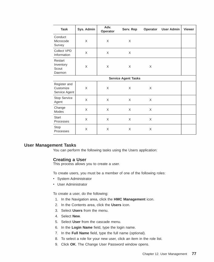
Task Sys. AdminAdv.
OperatorServ. Rep Operator User Admin Viewer
ConductMicrocodeSurvey
X X X
Collect VPDInformation
X X X
RestartInventoryScoutDaemon
X X X X
Service Agent Tasks
Register andCustomizeService Agent
X X X X
Stop ServiceAgent
X X X X
ChangeModes
X X X X
StartProcesses
X X X X
StopProcesses
X X X X
User Management TasksYou can perform the following tasks using the Users application:
Creating a UserThis process allows you to create a user.
To create users, you must be a member of one of the following roles:
v System Administrator
v User Administrator
To create a user, do the following:
1. In the Navigation area, click the HMC Management icon.
2. In the Contents area, click the Users icon.
3. Select Users from the menu.
4. Select New.
5. Select User from the cascade menu.
6. In the Login Name field, type the login name.
7. In the Full Name field, type the full name (optional).
8. To select a role for your new user, click an item in the role list.
9. Click OK. The Change User Password window opens.
Chapter 12. User Management 77
10. In the first field of the Change User Password window, type the user’s password.
11. Type the same password again in the Retype new password field.
12. Click OK.
The new user displays in the Contents area.
Note: It is strongly recommended that you create a user named hscpe for softwarefixes and updates from your software support representative. Supportrepresentatives may need to log in to your HMC using this user name when theyare analyzing a problem.
Editing User InformationTo edit user information, you must be a member of one of the following roles:
v System Administrator
v User Administrator
To edit user information, do the following:
1. In the Navigation area, click the HMC Management icon.
2. In the Contents area, double-click the Users icon.
3. In the Contents area, right-click the appropriate User icon.
4. Select Properties .
5. Edit the user’s base information (Login name, Full name, and User role).
6. Click OK. The Change User Password window opens.
7. Type the user’s password in each field.
8. Click OK.
Viewing User DefinitionsSometimes it is useful to review a user’s definitions to make sure you have correctlyconfigured the user’s access. For more information about roles and access, see “Rolesand Tasks” on page 72.
To view user definitions, you must be a member of one of the following roles:
v System Administrator
v User Administrator
To view a user’s definitions, including the assigned Login name, Full name, and Userrole, do the following:
1. In the Navigation area, click the HMC Management icon.
2. In the Contents area, double-click the Users icon.
3. In the Contents area, right-click the appropriate User icon.
4. Select Properties .
At this point, you can also edit any user information.
78 IBM Hardware Management Console for pSeries Installation and Operations Guide
Deleting a UserTo delete a user, you must be a member of one of the following roles:
v System Administrator
v User Administrator
To delete a user from the system, do the following:
1. In the Navigation area, click the HMC Management icon.
2. In the Contents area, double-click the Users icon.
3. In the Contents area, right-click the appropriate User icon.
4. Select Delete.
5. Click OK to confirm that you want to delete this user.
The user is removed from the contents area and no longer has access to the HMCmanagement environment. Some reserved users cannot be deleted.
Changing PasswordsTo change user passwords, you must be a member of one of the following roles:
v System Administrator
v User Administrator
To change a user’s password, do the following:
1. In the Navigation area, click the HMC Management icon.
2. In the Contents area, double-click the Users icon.
3. In the Contents area, right-click the appropriate User icon.
4. Select Change Password .
5. Type the new password in the first field.
6. Confirm the new password by typing it again in the Retype new password field.
7. Click OK.
Chapter 12. User Management 79

80 IBM Hardware Management Console for pSeries Installation and Operations Guide
Chapter 13. Basic System Management Tasks
This chapter describes how to perform system and frame management tasks. Thischapter also includes information about system profiles.
Managing the SystemYou can perform the tasks discussed in this chapter when the managed system isselected in the Contents area. A managed system is shown below a ″frame″ in theContents area. A frame manages a collection of managed systems.
The HMC communicates with the managed system to perform various systemmanagement, service, and partitioning functions. Systems connected to an HMC arerecognized automatically by the HMC, and are then shown in the Contents area.
You can connect up to two HMCs to each managed system by using the serial cablethat was provided with the HMC. You can also manage multiple systems with one HMC.For more information about using two HMC connected to one managed system, seeChapter 11, “Using Two HMCs Connected to One Managed System” on page 69.
To view more information about the managed system, click on the Server Managementicon in the Navigation area. The Contents area expands to show a frame, which youcan then expand to show information about the managed system, including its name, itsstate, and the operator panel value.
To expand your view of the managed system’s properties, click the plus sign (+) next tothe managed system’s name to view its contents.
In the Contents area, you can also select the managed system by right-clicking on themanaged system icon to perform the following:
v Power the managed system on or off
v View the managed system’s properties
v Open and close a terminal window
v Create, restore, back up, and remove system profile data
v Rebuild the managed system
v Release the HMC lock on this managed system
v Delete the managed system from the HMC graphical user interface
You can also access these options by clicking on the managed system and thenclicking Selected on the menu.
81
Powering On the Managed SystemYou can use your HMC to power on the managed system.
To power on the managed system, you must be a member of one of the following roles:
v System Administrator
v Advanced Operator
v Operator
v Service Representative
To power on the managed system, do the following:
1. In the Navigation area, click the Partition Management icon.
2. In the Contents area, select the managed system.
3. In the menu, click Selected .
4. Select Power On .
You are asked to select a power-on mode from the following:
v Partition Standby
v Full System Partition
v System Profile
The next section discusses each of these power-on modes.
Note: You must power off your managed system to switch between using the FullSystem Partition and using either logical or affinity partitions. You must alsopower off the system between activating logical partitions and affinity partitions.
Partition StandbyThe Partition Standby power-on option allows you to create and activate logicalpartitions. When the Partition Standby power-on is completed, the operator panel on themanaged system displays LPAR..., indicating the managed system is ready for you touse the HMC to partition its resources.
Note: The Full System Partition is listed as Not Available because the managedsystem was powered on using the Partition Standby option.
For more information about partitions, see Chapter 4, “Partitioning” on page 19.
Full System PartitionThe Full System Partition power-on option allows you to use all of the system’sresources on one operating system after the system has been powered on. This is thetraditional single-system method of using your system’s resources.
The physical operator panel on your managed system displays progress codes whenyou boot the system to this mode.
82 IBM Hardware Management Console for pSeries Installation and Operations Guide
Power-On OptionsIf you select the Full System Partition option, you can then select one of the followingprofiles:
Power On NormalThis option boots the operating system as previously specified in the SMSsettings. Depending on what is specified in the SMS settings, different boottypes may result. Refer to the documentation provided with your managedsystem for a complete description of this power on option.
Power On SMSThis profile is similar to Power On Diagnostic Stored Boot List Profile, exceptthe system boots using the default boot list that is stored in the systemfirmware.
Power On Diagnostic Stored Boot ListThis profile causes the system to perform a service mode boot using theservice mode boot list saved on the managed system. If the system boots AIXfrom the disk drive and AIX diagnostics are loaded on the disk drive, AIX bootsto the diagnostics menu.
Using this profile to boot the system is the preferred way to run onlinediagnostics.
Power On Diagnostic Default Boot ListThis profile boots to the System Management Services (SMS) menus. TheSMS menus include:
v Password Utilities
v Display Error Log
v Remote Initial Program Load Setup
v SCSI Utilities
v Select Console
v MultiBoot
v Select Language
v OK Prompt
For more information about SMS menus, see the PCI Adapter PlacementReference, order number SA38-0538.
Power On Open Firmware OK PromptThis profile is used only by service representatives to obtain additional debuginformation. When this selection is enabled, the system boots to the openfirmware prompt.
To learn more about these power-on options, see the service documentation for yourmanaged system.
For more information about the Full System Partition, see “Full System Partition” onpage 19.
Chapter 13. Basic System Management Tasks 83
System ProfilesThe System Profile option powers on the system according to a predefined set ofprofiles.
Note: The profiles are activated in the order in which they are shown in the systemprofile.
For more information about system profiles, see “Profiles” on page 21.
Powering Off the Managed SystemYou can also use your HMC to power off the managed system. Ensure that all partitionshave been shut down and their states have changed from Running to Ready.
To shut down a partition, do the following:
1. Open the partition’s virtual terminal window.
2. Log in to the operating system that is installed on that partition.
3. Run the shutdown command.
To power off the managed system, you must be a member of one of the following roles:
v System Administrator
v Advanced Operator
v Service Representative
To power off the managed system, do the following:
1. In the Contents area, select the managed system.
2. In the menu, click Selected .
3. Select Power Off .
When you power off the managed system, each partition associated with that managedsystem also powers off.
Viewing Managed System PropertiesTo view your managed system’s configuration and capabilities, use the propertieswindow.
Any user can view managed system properties.
To view your managed system’s properties, do the following:
1. In the Contents area, select the managed system.
2. In the menu, click Selected .
3. Select Properties .
If you have powered on your system using the Full System Partition option, theHMC displays the system’s name, partition capability, state, serial number, modeland type, and policy information. A system that is powered on using the Partition
84 IBM Hardware Management Console for pSeries Installation and Operations Guide
Standby option displays this information, as well as available and assignedprocessors, memory, I/O drawers and slots, and policy information. The Processortab displays information that is helpful when performing Dynamic Logical Partitioningprocessor tasks.
Use the Processor tab to view the processor status, the processor state, andwhether a processor is assigned to a partition. The information in the Processor tabis also helpful when you need to know if processors are disabled and therefore arenot able to be used by any partition. For more information about recoveringresources, see Appendix C, “Error Messages and Recovery Information” onpage 165.
Use the Policy tab to perform the following tasks:
v Power off the managed system after all the partitions are powered off.
v Set the Common Service Processor Surveillance (CSP) Policy. The CSPSurveillance Policy is a program that monitors the managed system. If the CSPdoes not detect the HMC, it logs an error to the CSP error log. If the policy is notenabled, the CSP does not log an error when the managed system is notdetected.
Managing Profile DataYou can back up, restore, initialize, and remove profiles that you have created. Thissection describes each of these options.
Backing Up Profile DataTo back up profile data, you must be a member of one of the following roles:
v System Administrator
v Advanced Operator
v Service Representative
Note: This is not a concurrent procedure. When the data is restored, the managedsystem powers on to Partition Standby.
To back up profile data, do the following:
1. In the Contents area, select the managed system.
2. From the menu, choose Selected .
3. From the menu, select Profile Data .
4. From the menu, select Backup .
5. Type the name you want to use for this backup file.
6. Click OK.
Restoring Profile DataSelecting this menu item restores profile data to the system from the local file system.
To restore profile data, you must be a member of one of the following roles:
v System Administrator
Chapter 13. Basic System Management Tasks 85
v Advanced Operator
v Service Representative
To restore profile data, do the following:
1. In the Contents area, select the managed system.
2. From the menu, choose Selected .
3. From the menu, select Profile Data .
4. From the menu, select Restore .
5. Select the profile information you want to restore from the list of backup files.
6. Select a restore option from the following list, and then click OK.
Full restore from selected backup fileThis option restores all profile data using your backup file only. Profilemodifications performed after the selected backup file was created will belost.
Backup priority - merge current profile and backupThis option merges the stored backup with recent profile activity. Ifinformation conflicts, the stored backup data is restored over the recentprofile activity.
Managed system priority - merge current profile and backupThis option merges recent profile activity with the stored backup. Ifinformation conflicts, the recent profile activity is restored over the storedbackup data.
Initializing Profile DataWhen you initialize profile data, you return the HMC to its original state. After youperform this task, any profiles that you created are erased.
To initialize profile data, you must be a member of one of the following roles:
v System Administrator
To initialize profile data, do the following:
1. In the Contents area, select the managed system.
2. From the menu, choose Selected .
3. From the menu, select Profile Data .
4. From the menu, select Initialize . A warning message window opens. If you are sureyou want to initialize profile data, click Yes.
Removing Profile DataTo remove stored profile data, you must be a member of one of the following roles:
v System Administrator
v Service Representative
v Advanced Operator
86 IBM Hardware Management Console for pSeries Installation and Operations Guide
To remove stored profile data, do the following:
1. In the Contents area, select the managed system.
2. From the menu, choose Selected .
3. Select Profile Data .
4. Select Remove .
5. Select the profile data that you want to remove.
6. Click OK.
Deleting the Managed System from the Contents AreaIf you no longer want to manage a particular system, you can delete it from theContents area.
Note: Do not disconnect the serial cable from the hardware before you delete themanaged system from the Contents area.
To delete the managed system from the Contents area, you must be a member of theSystem Administrator role.
To delete the managed system from the Contents area, do the following:
1. In the Contents area, select the managed system.
2. In the menu, click Selected .
3. Select Delete from the drop-down menu.
4. Click Yes to delete the managed system from the Contents area.
5. Disconnect the serial cable from the managed system.
The managed system’s icon is removed from the Contents area, and the connection isbroken between the HMC and the managed system.
Rebuilding the Managed SystemRebuilding the managed system acts much like a refresh of the managed systeminformation. Rebuilding the managed system is useful when the system’s state indicatorin the Contents area is shown as Recovery. The Recovery indicator signifies that thepartition and profile data stored in the managed system must be refreshed.
This operation is different from performing a refresh of the local HMC panel. In thisoperation, the HMC reloads information stored on the managed system.
Any user can rebuild the managed system.
To rebuild the managed system, do the following:
1. In the contents area, select the managed system.
2. In the menu, click Selected .
3. Select Rebuild Managed System .
Chapter 13. Basic System Management Tasks 87
After you select Rebuild Managed System , current system information displays.
Releasing an HMC Lock on the Managed SystemPerform this task only if you have two HMCs connected to your managed system andone of the HMCs is not responding. For more information, see “Releasing an HMC Lockon the Managed System” on page 237.
88 IBM Hardware Management Console for pSeries Installation and Operations Guide
Resetting the Operating System on a PartitionThe HMC enables the operating system on a partition to be reset when errors areencountered in the operating system. The system can undergo either a soft or hardreset, as follows:
Soft ResetSoft reset actions are determined by your operating system’s policy settings.Depending on how you have configured these settings, the operating systemmight do the following:
v Perform a dump of system information
v Restart automatically
For more information about configuring your operating system’s policy settings,refer to your operating system documentation.
Hard ResetA hard reset virtually powers off the system.
Attention: Issuing a hard reset forces termination and can corruptinformation. Use this option only if the operating system is disrupted andcannot send or receive commands.
To reset the operating system, you must be a member of one of the following roles:
v System Administrator
v Advanced Operator
v Service Representative
To reset the operating system on a partition, do the following:
1. In the Contents area, select the partition running the operating system you want toreset.
2. In the menu, click Selected .
3. Select Reset .
4. Select Operating System .
5. Select whether you would like to perform a hard or soft operating system reset.
6. Click Yes.
Managing a Frame of Managed Systems and Resources Connected to the HMCA frame is a collection of managed systems and resources. Each frame is shown in theContents area as the root of a resource tree; managed systems are listed underneatheach frame.
Any user role can refresh a frame.
If a managed system that is part of a frame does not show up under the frame in theContents area, you should refresh the frame as follows:
Chapter 13. Basic System Management Tasks 89
1. In the Contents area, select the frame.
2. In the menu, click Selected .
3. Select Refresh .
The Contents area is updated to show the latest frame information.
If your managed system is a frame housing multiple managed systems and resources,you can use your HMC to perform the following frame-management tasks:
v Initialize a frame’s associated managed systems and resources
v View frame properties, such as machine type, model, and I/O information
v Deactivate and reset the managed system’s CSP
v Deactivate I/O drawers
If your managed system is not a frame housing multiple managed systems andresources, these tasks are not enabled. The only option available to you is to refreshthe frame.
Initializing a Frame’s Managed Systems and ResourcesThe frame must be manually powered on before its managed systems and otherresources can be powered on.
Perform this task the first time that the frame is plugged into the wall, and wheneverresources in a frame have been added, removed, or recabled.
To initialize a frame’s managed systems and resources, you must be a member of oneof the following roles:
v System Administrator
v Service Representative
To power on the managed resources in the frame, do the following:
1. In the Contents area, select the frame.
2. In the menu, click Selected .
3. Select Initialize . The Frame Initialization window opens.
4. Click Yes.
Viewing Frame PropertiesThe frame’s properties panel shows you all of the managed systems and I/O drawersthat exist in the frame.
To view frame properties, you must be a member of one of the following roles:
v System Administrator
v Service Representative
To view Frame properties, do the following:
1. In the Contents area, select the frame.
90 IBM Hardware Management Console for pSeries Installation and Operations Guide
2. In the menu, click Selected .
3. Select Properties . The Frame Properties window opens. The General tab displaysthe frame’s serial number. The Systems tab displays the managed systemsassociated with the frame, and includes each managed system’s machine type,model, and serial number. This tab also displays the cage number that houses eachmanaged system. The I/O Drawers tab displays the I/O drawers installed in theframe. This panel displays the I/O drawer machine type, mode, and serial number. Italso displays the cage number that houses the I/O drawer and each associatedmanaged system’s machine type, model, and serial number. If the I/O is notassociated with a managed system, this field is blank.
Deactivating a Managed System’s Service ProcessorThis option allows you to deactivate service processors on managed systems that areassociated with the frame. Service processors are usually deactivated by servicepersonnel in order to take the managed system out of the frame for service or repair.
To deactivate a managed system’s service processor, you must be a member of one ofthe following roles:
v System Administrator
v Service Representative
To deactivate a managed system’s service processor, do the following:
1. In the Contents area, select the frame.
2. In the menu, click Selected .
3. Select Deactivate .
4. Select Service Processor . The Deactivate Service Processor window opens anddisplays managed systems.
5. Select the managed system or systems whose service processors you want todeactivate.
6. Click OK.
Resetting a Managed System’s Service ProcessorThis option allows you to reset a CSP on a managed system associated with the frame.The service processor may need to be reset if a hardware error has occurred on themanaged system.
Note: If partitions are running on a managed system whose service processor is reset,they will be halted abruptly when you issue the reset. If possible, shut down thepartitions before continuing.
To reset a managed system’s service processor, you must be a member of one of thefollowing roles:
v System Administrator
v Service Representative
To reset a managed system’s service processor, do the following:
Chapter 13. Basic System Management Tasks 91
1. In the Contents area, select the frame.
2. In the menu, click Selected .
3. Select Reset .
4. Select Service Processor . The System Reset window opens and displaysmanaged systems.
5. Select the managed system or systems that you want to reset.
6. Click OK.
Deactivating a Frame’s I/O DrawersThis option allows you to deactivate the I/O drawers associated with the frame. I/Odrawers are usually deactivated by service personnel in order to take them out of theframe for service or repair.
To deactivate the I/O drawers associated with the frame, you must be a member of oneof the following roles:
v System Administrator
v Service Representative
To deactivate the I/O drawers associated with the frame, do the following:
1. In the Contents area, select the frame.
2. In the menu, click Selected .
3. Select Deactivate .
4. Select I/O Drawer . The Deactivate I/O Drawer window opens and displays the I/Odrawers associated with the frame.
5. Select the I/O drawer or drawers that you want to deactivate.
6. Click OK.
92 IBM Hardware Management Console for pSeries Installation and Operations Guide
Chapter 14. Using Capacity Upgrade on Demand
Capacity Upgrade on Demand (CUoD) allows you use the HMC to non-disruptivelyactivate extra resources while the system is operating. If you ordered a CUoD-capablesystem, additional resources were shipped with the system and can be enabled byusing special CUoD activation codes.
Note: CUoD is not supported on systems running Linux in the full system partition.
You can use the HMC to perform the following Capacity Upgrade on Demand functions:
v Display license agreements
v Display the extra resources preinstalled on your managed system
v Type a resource activation code
v Activate extra resources
v Display CUoD status messages
Activating Process for Capacity Upgrade on DemandThe CUoD process begins when you determine a potential need for more processingcapability in the future and want to have the hardware installed on the server now. TheCUoD feature of your server gives you the processor capacity that you might need inthe future on your system today. If CUoD features are ordered for your server, they areincluded in the server when it is delivered. When the additional processors become anecessity, use the following steps to activate them:
1. Determine the number of standby processors you want to activate.
2. Contact your sales representative or business partner to place an order for anumber of CUoD Activation Features.
3. The sales representative places an order to the system or feature coordinator forthe specific number of CUoD activation features. The order specifies the number ofadditional processors you have requested to add.
4. The sales representative is provided with a reminder (through the system or featureconfigurator) that Vital Product Data (VPD) from the server must be sent to IBM tofulfill the order. To process the order, you must send VPD to IBM. You can sendVPD in either of two ways:
v Electronic Process (Electronic Service Agent)
a. Ensure TCP/IP is set up and started.
b. Run the Electronic Service Agent:
1) In the Navigation area, click the Service Applications icon.
2) In the Contents area, double-click the Service Agent icon.
3) In the Service Applications window, click Service Agent UI .
4) Type the Service Agent password. The default password, which is casesensitive, is:
password
5) In the Navigation Window, click SAS-Connections .
93
6) Click VPD.
7) You are presented with several options for transmitting VPD. You canselect to send VPD immediately or to send it periodically.
Note: For more information about using and setting up the ElectronicService Agent, see Chapter 18, “Service Agent” on page 137.
v Web-based VPD entry:
a. Collect the Vital Product Data from the server by following these steps:
1) Access the internet from any available system and go to the followingWeb site:
http://www.ibm.com/servers/eserver/pseries/cuod/index.html
2) Record the processor order information. For more information, see“Viewing and Saving Capacity Upgrade on Demand Processor OrderInformation” on page 96.
3) Type the requested data you collected from previous steps.
4) Retrieve the CUoD activation code from the Web or wait to receive theCUoD activation code by mail. The CUoD activation code will be postedon the Web usually within one business day of receiving the order on themanufacturing floor if the VPD data have already been sent. To retrievethe CUoD activation code on the Web, follow these steps
a) Go to the following Web site:
http://www.ibm.com/servers/eserver/pseries/cuod/index.html
b) On the web page, enter the machine type and serial number of thetarget server.
c) Print and/or record the CUoD activation code displayed on the webpage.
5) Type the CUoD activation code. To use the HMC to perform this task, dothe following:
a) In the Contents area, select the managed system.
b) Select Capacity Upgrade on Demand .
c) Select Processor .
d) Select Processor Activate .
e) Type the activation code supplied to you by your representative.
f) Click OK. If you entered a valid activation code, The CUoDActivation Success window opens.
g) Click OK.
5. Assign the activated processors to a partition. If you are using dynamicreconfiguration, you do not have to reboot the system to use the processors. If youare not using dynamic reconfiguration, you must reboot the managed system beforethe newly activated processors can be utilized.
Before adding processors to a partition running Linux, you must stop Linux partitionsand then restart them after you have assigned the processors.
For more information about assigning processors dynamically, see“AddingProcessors to A Partition Dynamically” on page 105.
94 IBM Hardware Management Console for pSeries Installation and Operations Guide
6. Begin using the new capacity.
If you encounter any problems using the above process, do the following:
v For problems with a processor capacity card (part failure), call your service provider.Service personnel can contact their second level of support to reset the appropriatecapacity after the card has been replaced with a new card (A new CUoD activationcode must be generated and applied).
v For problems with understanding technical details of Capacity Upgrade on Demand,review the appropriate sections in this guide. Work with the second level of supportfor your area.
v For problems with administrative details of Capacity Upgrade on Demand, review theappropriate sections in this planning guide. Work with the account teams in yourarea.
Accepting the License AgreementDuring the first time you power on a CUoD-capable system using an HMC, a licenseagreement panel displays on the HMC attached to the CUoD system. Only users withthe System Administrator role can accept the agreement. You must accept the CUoDlicense agreement in order to power on the system completely. If you choose not toaccept the agreement, you must power off the managed system, have a servicerepresentative remove all the CUoD hardware, and then power the machine back onagain. If the you do not accept the license agreement and did not have the CUoDhardware removed, the same license agreement panel opens on the next power on.
You can view the license agreement at any time. To view the license agreement, do thefollowing:
1. Select the managed system.
2. Select Capacity Upgrade on Demand .
3. Select License Agreement .
Displaying Capacity Upgrade on Demand ResourcesYou can display the following information about your CUoD processors:
v Number of processors installed
v Number of processors in use
v Number of activated processors
v Processor capacity condition
To display CUoD resource information, do the following:
1. In the Contents area, select the managed system.
2. Select Capacity Upgrade on Demand .
3. Select Processor .
4. Select Processor Capacity Setting .
Chapter 14. Using Capacity Upgrade on Demand 95
Information about your CUoD resources displays.
Viewing and Saving Capacity Upgrade on Demand Processor Order InformationYou can save CUoD ordering information to either an ftp site or to a diskette on theHMC.
To save CUoD order information, do the following:
1. In the Contents area, select the managed system.
2. Select Capacity Upgrade on Demand .
3. Select Processor .
4. Select Processor Capacity Setting .
5. Click Display Order Information . The following information about your processororder displays:
v System type
v System serial number
v CUoD capacity card CCIN
v CUoD capacity card serial number
v CUoD capacity card unique identifier
v CUoD resource identifier
v CUoD processors activated
v CUoD processor sequence number
v CUoD processor entry check
6. If you want to save this information, click Save As .
7. Select where you want to save the order information and complete the fields withthe appropriate information.
Activating Capacity Upgrade on Demand ResourcesThis section describes how to enter an activation code to activate Capacity Upgrade onDemand resources.
To activate CUoD resources, do the following:
1. In the Contents area, select the managed system.
2. Select Capacity Upgrade on Demand .
3. Select Processor .
4. Select Processor Activate .
5. Type the activation code supplied to you by your representative.
6. Click OK. If you entered a valid activation code, The CUoD Activation Successwindow opens.
7. Click OK. If you are using dynamic reconfiguration, you do not have to reboot thesystem to use the processors. If you are not using dynamic reconfiguration, youmust reboot the managed system before the newly activated processors can beutilized.
96 IBM Hardware Management Console for pSeries Installation and Operations Guide

Before adding processors to a partition running Linux, you must stop Linux partitionsand then restart them after you have assigned the processors.
Chapter 14. Using Capacity Upgrade on Demand 97

98 IBM Hardware Management Console for pSeries Installation and Operations Guide
Chapter 15. Server Management Tasks
This chapter provides information about the server management tasks you can perform.
To activate more than one partition, you must power on your managed system using thePartition Standby power-on option. For more information about power-on options, see“Powering On the Managed System” on page 82.
Creating PartitionsThis section describes how to create logical partitions.
To create partitions, you must be a member of one of the following roles:
v System Administrator
v Advanced Operator
Preparing Your System for PartitioningTo prepare your system for partitioning, do the following:
1. Log in to the HMC.
2. In the Navigation area, click the console’s icon to expand the tree.
3. In the Navigation area, double-click the Server and Partition folder icon underneaththe managed system. Then, click the Server Management icon to select yourpreferred partition environment. The Contents area now lists the available managedsystems.
4. In the Contents area, select the managed system for which you want to configurepartitions.
5. With the managed system selected in the Contents area, choose Selected from themenu.
If your managed system is currently powered on using the Partition option, see“Creating Logical Partitions”.
If your managed system is currently powered off, continue with the next step.
6. Select Power On .
7. Select Partition Standby as a power-on option.
8. Click OK to power on the managed system. In the Contents area, the managedsystem’s state changes from No Power to Initializing . . . and then to Ready. Whenthe state reads Ready and the virtual Operator Panel Value reads LPAR . . . , see“Creating Logical Partitions”. For more information about managed system states,see “Managed System Operating States” on page 227.
Creating Logical Partitions1. In the Contents area, select the managed system.
2. From the selected menu, select Create .
3. Select Logical Partition . The Create Logical Partition and Profile wizard opens.
99
4. In the first window of the Create Logical Partition and Profile wizard, provide aname for the partition profile that you are creating. Use a unique name for eachpartition that you create. Names can be up to 31 characters long.
5. Click Next .
6. Type the name of the profile you are creating for this partition.
7. Click Next .
8. Select the desired, minimum, and maximum number of processors you want forthis partition profile. The HMC shows you the total number of processorsconfigured for use by the system, and prompts you to enter your desired, minimumand maximum processor amounts for this partition profile. The following is adescription of each term:
DesiredDesired amounts are used if they are available at the time of activation.
MinimumMinimum amounts define the processors you require for this partition. Ifthese processors are not available at the time you attempt to activate theprofile, the partition does not activate.
MaximumMaximum amounts define the largest number of processors you canassign to this partition. If you attempt to dynamically move an amount ofprocessors to this partition that exceeds this number, an error messagedisplays, and the operation stops.
9. Click Next .
10. Select the desired and minimum number of memory. The HMC shows you the totalamount of memory configured for use by the system, and not the amount that iscurrently available. The HMC prompts you to enter your desired, minimum andmaximum memory amounts for this partition profile. The following is a descriptionof each term:
DesiredDesired amounts are used if they are available at the time of activation.
MinimumMinimum amounts define the memory amount you require for thispartition. If this memory amount is not available at the time you attempt toactivate the profile, the partition does not activate.
MaximumMaximum amounts define the largest amount of memory you can assignto this partition. If you attempt to dynamically move an amount of memoryto this partition that exceeds this number, an error message displays andthe operation stops.
Enter the amount of desired and required memory in 1 gigabyte (GB) incrementsand 256 megabyte (MB) increments. You must have a minimum of 1 GB for eachpartition.
100 IBM Hardware Management Console for pSeries Installation and Operations Guide
Some special memory issues must be considered when you assign memory topartitions. For more information about these memory issues, see “Memory” onpage 23.
11. Click Next .
12. The left side of the new window displays the I/O drawers available and configuredfor use. To expand the I/O tree to show the individual slots in each drawer, clickthe icon next to each drawer. Because the HMC groups some slots, if you attemptto assign a member of one of these ″grouped″ slots to a profile, the entire group isautomatically assigned. Groups are indicated by a special icon namedGroup_XXX .
Click on the slot for details about the adapter installed in that slot. When you selecta slot, the field underneath the I/O drawer tree lists the slot’s class code andphysical location code.
Note: The slots in the I/O Drawers field are not listed in sequential order.
13. Select the slot you want to assign to this partition profile and click Add . If you wantto add another slot, repeat this process. Slots are added individually to the profile;you can add slots one at a time, unless they are grouped. Minimally, add a bootdevice to the required list box.
There are two groups to which you can add adapters: a Required and a Desiredgroup. Desired adapters will be used if they are available at the time of activation.Required adapters are adapters that you require for this partition. If the adapters inthis group are not available at the time of activation, the partition does not activate.
If you want to install an operating system on this partition using the managedsystem’s CD-ROM drive, assign the CD-ROM to this partition profile.
14. Click Next . This window allows you to set service authority and boot modepolicies for this partition profile.
If you want this partition to be used by service representatives to perform systemfirmware updates and set other system policy parameters, select the Set ServiceAuthority check box.
Select the boot mode that you want for this partition profile. For a description ofeach boot mode, see “Power-On Options” on page 83.
15. Click Next . This window supplies you with summary information about thispartition.
16. Review the information to ensure that you have the appropriate resourcesassigned to this partition.
17. If you want to change the configuration, click Back . Otherwise, click Finish tocreate the partition and profile.
18. The new partition, along with the default profile you just created, displaysunderneath the Managed System tree in the Contents area.
After you have created a partition, you must install an operating system and configureInventory Scout Services on the HMC and on the partition. To install an operatingsystem on the partition and configure Inventory Scout Services on that partition, refer to
Chapter 15. Server Management Tasks 101
the installation information shipped with your operating system. To configure InventoryScout Services for this partition on the HMC, see “Configuring the Inventory ScoutServices Profile” on page 65.
Note: If you want to use the managed system’s CD-ROM to install operating systemson your partitions, it is recommended that you create at least two profiles foreach partition. Create one profile that has the managed system’s CD-ROMassigned to it, and another profile without the managed system’s CD-ROM.Using this method, you can release the managed system’s CD-ROM bydeactivating the profile that has the CD-ROM and activating the profile that doesnot have the CD-ROM. For more information about creating partition profiles, see“Creating Additional Partition Profiles” on page 121.
Creating Affinity PartitionsDepending on your managed system’s configuration, you may be able to create aspecial group of logical partitions called affinity partitions. The process of creating agroup of affinity partitions is similar to the process of creating logical partitions. The onlydifference is that the system does the processor and memory assignment for you.
To determine if your managed system is capable of running affinity partitions, checkyour managed system’s properties. For more information about viewing your managedsystem’s properties, see “Viewing Managed System Properties” on page 84.
To create an affinity partition, do the following:
1. In the Contents area, select the managed system.
2. From the selected menu, select Affinity Logical Partition .
3. Select Create to open the Affinity Partition Setup wizard.
4. In the first window of the Create Affinity Partition wizard, select the type of affinitypartition you want to create.
5. Click OK.
6. In the second window of the Create Affinity Partition wizard, type a name for thefirst affinity partition that you are creating. Use a unique name that is up to 31characters long.
In the second field, type a name for the default profile.
Then select which boot mode this affinity partition will use when you activate it.
Select the Set Service Authority check box if you want this partition to be usedby service representatives to perform system-firmware updates and set othersystem policy parameters.
Enter this information for each of the affinity partitions you want to create. To selectanother affinity partition, click on the appropriate ALPAR tab on the top of thewindow.
7. Click Next .
8. The left side of the new window now displays the I/O drawers available andconfigured for use. To expand the I/O tree to show the individual slots in eachdrawer, click the icon next to each drawer. Because the HMC groups some slots, if
102 IBM Hardware Management Console for pSeries Installation and Operations Guide
you attempt to assign a member of one of these ″grouped″ slots to a profile, theentire group is automatically assigned. Groups are indicated by a special iconnamed Group_XXX .
Click on the slot for details about the adapter installed in that slot. When you selecta slot, the field underneath the I/O drawer tree lists the slot’s class code andphysical location code.
Note: The slots in the I/O Drawers field are not listed in sequential order.
9. Select the slot you want to assign to this default affinity profile and click Add . Ifyou want to add another slot, repeat this process. Slots are added individually tothe profile; you can only add slots one at a time, unless they are grouped.Minimally, add a boot device to the required list box.
If you want to install an operating system on this partition using the managedsystem’s CD-ROM drive, assign the CD-ROM to this partition profile.
10. Perform steps 6-9 for each affinity partition tab shown at the top of the screen.
11. If you want to change the configuration for any affinity partition, click Back .Otherwise, click Finish to create the group of affinity partitions.
12. The new affinity partitions, along with the default profiles you just created, displayunderneath the Managed System tree in the Contents area. A System Profile isalso created and is displayed underneath the managed system tree.
13. After you have created a partition, you must install an operating system on thepartition. To install an operating system on the partition, refer to the installationinformation provided with your operating system.
Note: If you want to use the managed system’s CD-ROM to install operatingsystems on your partitions, it is recommended that you create at least twoprofiles for each partition. Create one profile that has the managed system’sCD-ROM assigned to it, and another profile without the managed system’sCD-ROM. Using this method, you can release the managed system’sCD-ROM by deactivating the profile that has the CD-ROM and activatingthe profile that does not have the CD-ROM. For more information aboutcreating partition profiles, see “Creating Additional Partition Profiles” onpage 121.
Updating Affinity Partitions After Adding or Removing ManagedSystem ResourcesTo update affinity partitions after a service representative has added or removedresources on the managed system, you must be a member of one of the followingroles:
v System Administrator
v Advanced Operator
To update affinity partitions after adding or removing managed system resources, do thefollowing:
1. In the Contents area, select the managed system.
2. From the selected menu, select Affinity Logical Partition .
3. Select Update .
Chapter 15. Server Management Tasks 103
4. The HMC will then assess what resources have been added or removed, and willask you if you would like to add or remove affinity partitions as appropriate. Formore information about adding new affinity partitions, see “Creating AffinityPartitions” on page 102. If you have removed resources from your managed system,the HMC lists the affinity partitions associated with the removed resources. Click OKto remove these affinity partitions.
Activating PartitionsTo activate a partition, select the partition itself, and click Activate from the Selectedmenu. A window opens that lists activation profiles. The default partition profile isautomatically highlighted, but you can activate the partition with any of the listedprofiles.
If the required resources you specified in the partition profile that you are using toactivate the partition exceed the amount of available resources, this partition does notactivate. All resources currently not being used by active partitions are consideredavailable resources. It is important that you keep track of your system’s resources at alltimes.
For service, you must also configure Inventory Scout Services for each partition youactivate. For more information about configuring Inventory Scout, see “Configuring theInventory Scout Services Profile” on page 65.
To activate partitions, you must be a member of one of the following roles:
v Operator
v Advanced Operator
v System Administrator
v Service Representative
Activating a Specific Partition ProfileTo activate a partition profile, do the following:
1. In the Contents area, select a partition profile.
2. On the menu, click Selected .
3. Select Activate .
4. The profile name is highlighted. Click OK to activate the partition profile.
The virtual operator panel next to the partition cycles through hardware boot sequenceerror and information codes, and then displays operating system error and informationcodes. For a complete description of these codes, refer to the hardware servicedocumentation provided with your managed system and the documentation providedwith your operating system.
Activating a Partition without Selecting a Specific Partition ProfileTo activate a partition without selecting a specific partition profile, do the following:
1. In the Contents area, select the partition.
2. On the menu, click Selected .
104 IBM Hardware Management Console for pSeries Installation and Operations Guide
3. Select Activate .
4. The default profile name is highlighted. Click OK. If you want to activate a differentprofile, select another profile in the list and then click OK.
Reactivating a Partition with a Partition ProfileReactivating a partition with a different profile requires shutting down the operatingsystem that is running in that partition and activating another profile.
To reactivate a partition with a partition profile, you must be a member of one of thefollowing roles:
v Operator
v Advanced Operator
v System Administrator
v Service Representative
To reactivate a partition with a different profile, do the following:
1. In the Contents area, select the partition for which you want to change profiles.
2. Open a terminal window for that partition to look at the operating system. To learnmore about opening a terminal window, read “Opening a Virtual Terminal Window”on page 128.
3. Run an appropriate shutdown command. The system shuts down the operatingsystem, and the partition’s state changes from Running to Ready in the Contentsarea.
4. In the Contents area, select the new partition profile you want to activate for thatpartition.
5. In the menu, click Selected .
6. Select Activate .
Reassigning Partition Resources DynamicallyYou can logically attach and detach a managed system’s resources to and from alogical partition’s operating system without rebooting.
Note: You can dynamically reassign I/O resources between affinity logical partitions,but not processor or memory resources.
Adding ResourcesYou can dynamically add processors, memory, and adapters to partitions.
Adding Processors to A Partition Dynamically: This task allows you to addprocessors to a partition without rebooting the partition’s operating system.
You can only add up to the amount of free system processors, or processors that arenot assigned to a running partition. This number cannot exceed the maximum numberspecified in this partition’s active profile. To learn more about this partition’s activeprofile, view the activated profile’s properties. To view profile properties, see “ViewingPartition Profile Properties” on page 121.
Chapter 15. Server Management Tasks 105
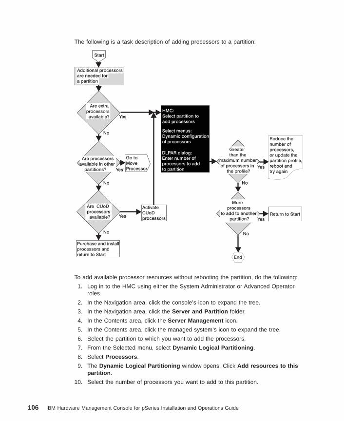
The following is a task description of adding processors to a partition:
Start
Go to
Move
Processor
End
Additional processors
are needed for
a partition
HMC:
Select partition to
add processors
Reduce the
number of
processors,
or update the
partition profile,
reboot and
try again
Return to Start
Are extra
processors
available?
Are processors
available in other
partitions?
Are CUoD
processors
available?
Purchase and install
processors and
return to Start
Activate
CUoD
processors
Select menus:
Dynamic configuration
of processors
DLPAR dialog:
Enter number of
processors to add
to partition
Greater
than the
maximum number
of processors in
the profile?
More
processors
to add to another
partition?
Yes
Yes
YesYes
Yes
No
No
NoNo
No
To add available processor resources without rebooting the partition, do the following:
1. Log in to the HMC using either the System Administrator or Advanced Operatorroles.
2. In the Navigation area, click the console’s icon to expand the tree.
3. In the Navigation area, click the Server and Partition folder.
4. In the Contents area, click the Server Management icon.
5. In the Contents area, click the managed system’s icon to expand the tree.
6. Select the partition to which you want to add the processors.
7. From the Selected menu, select Dynamic Logical Partitioning .
8. Select Processors .
9. The Dynamic Logical Partitioning window opens. Click Add resources to thispartition .
10. Select the number of processors you want to add to this partition.
106 IBM Hardware Management Console for pSeries Installation and Operations Guide
Note: If the Processor Information button appears underneath the Number ofCPUs to add field, the HMC has discovered disabled processors that youmight be able to deconfigure and free for system use. For more informationabout restoring these processors, see “Restoring Processor Resources” onpage 229.
11. In the Task timeout field, select the number of minutes you want the system towait before it stops the task.
12. In the Details field, select the level of feedback you would like to see while theHMC performs the task. Details shown include the operating system’s standardoutput and standard error information.
13. When you are finished selecting the information, click OK.
Adding Memory to A Partition Dynamically: This task allows you to add memory toa partition without rebooting the partition’s operating system. The following is a task
Chapter 15. Server Management Tasks 107
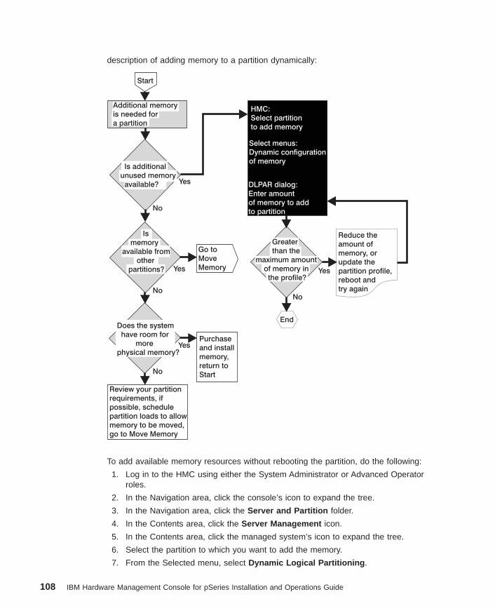
description of adding memory to a partition dynamically:
Start
Go to
Move
Memory
End
Additional memory
is needed for
a partition
HMC:
Select partition
to add memory
Does the system
have room for
more
physical memory?
Review your partition
requirements, if
possible, schedule
partition loads to allow
memory to be moved,
go to Move Memory
Purchase
and install
memory,
return to
Start
Select menus:
Dynamic configuration
of memory
DLPAR dialog:
Enter amount
of memory to add
to partition
Yes
Yes
Yes
Yes
No
No
No
No
Greater
than the
maximum amount
of memory in
the profile?
Is
memory
available from
other
partitions?
Is additional
unused memory
available?
Reduce the
amount of
memory, or
update the
partition profile,
reboot and
try again
To add available memory resources without rebooting the partition, do the following:
1. Log in to the HMC using either the System Administrator or Advanced Operatorroles.
2. In the Navigation area, click the console’s icon to expand the tree.
3. In the Navigation area, click the Server and Partition folder.
4. In the Contents area, click the Server Management icon.
5. In the Contents area, click the managed system’s icon to expand the tree.
6. Select the partition to which you want to add the memory.
7. From the Selected menu, select Dynamic Logical Partitioning .
108 IBM Hardware Management Console for pSeries Installation and Operations Guide
8. Select Memory .
9. The Dynamic Logical Partitioning window opens. Click Add resource to thispartition .
10. Select the amount of memory you want to add to this partition. The window showsyou how much free memory the system has for this partition’s use.
Note: If the Memory Information button appears underneath the Amount ofmemory to add field, the HMC has discovered an inconsistency betweenany partition’s Allocated and Requested memory amounts. Click this buttonto correct the requested memory value and free memory resources to thesystem. For more information about restoring memory, see “RestoringMemory Resources” on page 231.
11. In the Task timeout field, select the number of minutes you want the system towait before it stops the task.
12. In the Details field, select the level of feedback you would like to see while theHMC performs the task. Details shown include the operating system’s standardoutput and standard error information.
13. When you are finished selecting the correct information, click OK.
Adding Adapters to A Partition Dynamically: This task allows you to add I/Oadapters to a partition without rebooting the partition’s operating system. The following
Chapter 15. Server Management Tasks 109
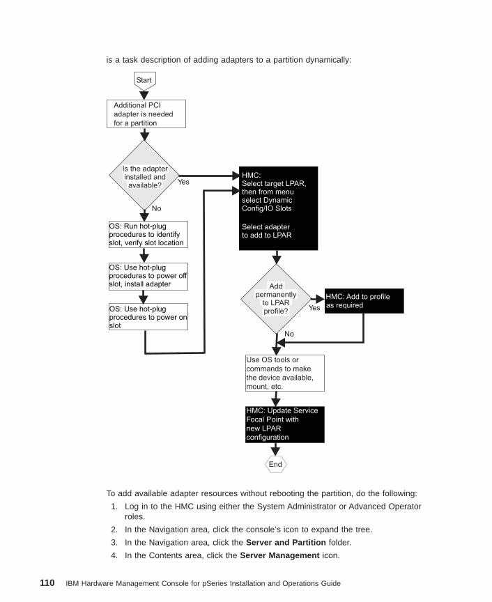
is a task description of adding adapters to a partition dynamically:
Start
End
OS: Run hot-plugprocedures to identifyslot, verify slot location
OS: Use hot-plugprocedures to power offslot, install adapter
OS: Use hot-plugprocedures to power onslot
HMC:Select target LPAR,then from menuselect DynamicConfig/IO Slots
Select adapterto add to LPAR
HMC: Add to profileas required
Use OS tools or
commands to make
the device available,
mount, etc.
HMC: Update Service
Focal Point with
new LPAR
configuration
Yes
Yes
No
No
Additional PCI
adapter is needed
for a partition
Is the adapterinstalled andavailable?
Addpermanently
to LPARprofile?
To add available adapter resources without rebooting the partition, do the following:
1. Log in to the HMC using either the System Administrator or Advanced Operatorroles.
2. In the Navigation area, click the console’s icon to expand the tree.
3. In the Navigation area, click the Server and Partition folder.
4. In the Contents area, click the Server Management icon.
110 IBM Hardware Management Console for pSeries Installation and Operations Guide
5. In the Contents area, click the managed system’s icon to expand the tree.
6. Select the partition to which you want to add the adapters.
7. From the Selected menu, select Dynamic Logical Partitioning .
8. Select Adapters .
9. The Dynamic Logical Partitioning window opens. Click Add resource to thispartition .
10. Select the free system adapters that you want to add to this partition.
Note: If the Adapter Information button appears underneath the Free systemadapters field, the HMC has discovered disabled adapters that you mightbe able to decontrolling and free for system use. For more informationabout restoring these adapters, see “Restoring Adapter Resources” onpage 230.
11. In the Task timeout field, select the number of minutes you want the system towait before it stops the task.
12. In the Details field, select the level of feedback you would like to see while theHMC performs the task. Details shown include the operating system’s standardoutput and standard error information.
13. When you are finished selecting the correct information, click OK.
Moving ResourcesYou can dynamically move processors, memory, and adapters among partitions.
Moving Processors from One Partition to Another: This task allows you to moveprocessors from one partition to another without rebooting either partition’s operatingsystem.
Chapter 15. Server Management Tasks 111
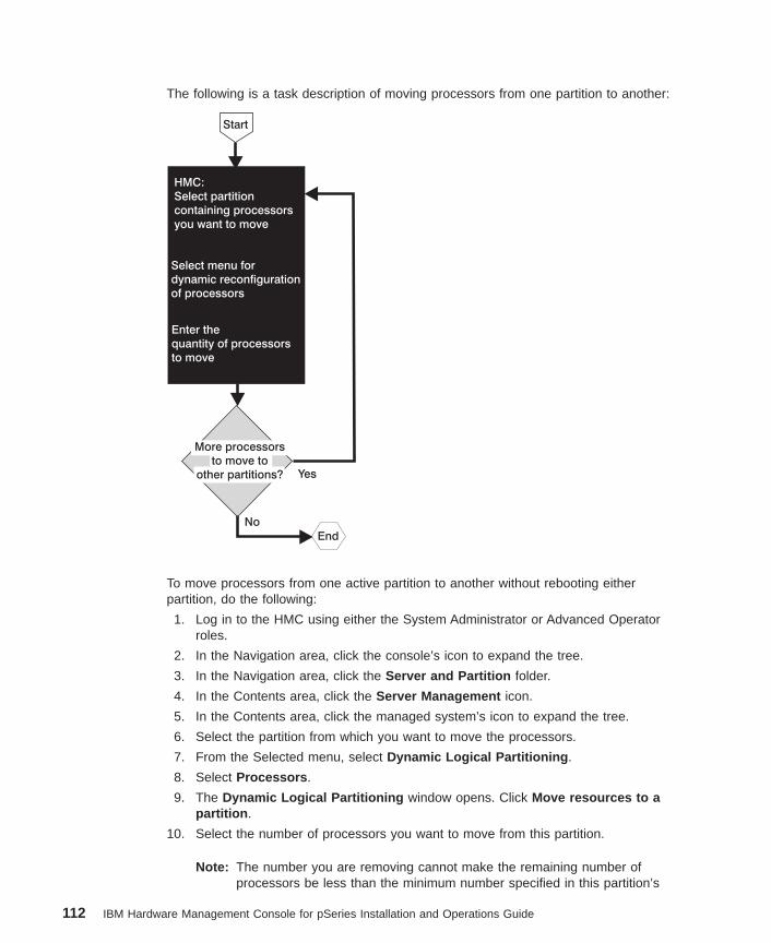
The following is a task description of moving processors from one partition to another:
Start
HMC:
Select partition
containing processors
you want to move
Select menu for
dynamic reconfiguration
of processors
Enter the
quantity of processors
to move
No
More processors
to move to
other partitions? Yes
End
To move processors from one active partition to another without rebooting eitherpartition, do the following:
1. Log in to the HMC using either the System Administrator or Advanced Operatorroles.
2. In the Navigation area, click the console’s icon to expand the tree.
3. In the Navigation area, click the Server and Partition folder.
4. In the Contents area, click the Server Management icon.
5. In the Contents area, click the managed system’s icon to expand the tree.
6. Select the partition from which you want to move the processors.
7. From the Selected menu, select Dynamic Logical Partitioning .
8. Select Processors .
9. The Dynamic Logical Partitioning window opens. Click Move resources to apartition .
10. Select the number of processors you want to move from this partition.
Note: The number you are removing cannot make the remaining number ofprocessors be less than the minimum number specified in this partition’s
112 IBM Hardware Management Console for pSeries Installation and Operations Guide
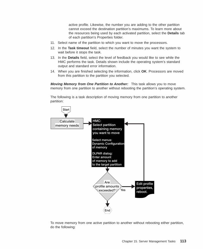
active profile. Likewise, the number you are adding to the other partitioncannot exceed the destination partition’s maximums. To learn more aboutthe resources being used by each activated partition, select the Details tabof each partition’s Properties folder.
11. Select name of the partition to which you want to move the processors.
12. In the Task timeout field, select the number of minutes you want the system towait before it stops the task.
13. In the Details field, select the level of feedback you would like to see while theHMC performs the task. Details shown include the operating system’s standardoutput and standard error information.
14. When you are finished selecting the information, click OK. Processors are movedfrom this partition to the partition you selected.
Moving Memory from One Partition to Another: This task allows you to movememory from one partition to another without rebooting the partition’s operating system.
The following is a task description of moving memory from one partition to anotherpartition:
Start
End
Select menus:
Dynamic Configuration
of memory
DLPAR dialog:
Enter amount
of memory to add
to the target partition
Yes
HMC:
Select partition
containing memory
you want to move
Are
profile amounts
exceeded?
Calculate
memory needs
Edit profile
properties,
reboot.
To move memory from one active partition to another without rebooting either partition,do the following:
Chapter 15. Server Management Tasks 113
1. Log in to the HMC using either the System Administrator or Advanced Operatorroles.
2. In the Navigation area, click the console’s icon to expand the tree.
3. In the Navigation area, click the Server and Partition folder.
4. In the Contents area, click the Server Management icon.
5. In the Contents area, click the managed system’s icon to expand the tree.
6. Select the partition from which you want to move the memory.
7. From the Selected menu, select Dynamic Logical Partitioning .
8. Select Memory .
9. The Dynamic Logical Partitioning window opens. Click Move resource to apartition .
10. Select the amount of memory you want to move from this partition.
Note: The number you are removing cannot make the remaining memory amountbe less than the minimum number specified in this partition’s active profile.To learn more about the resources being used by the activated partition,select the Details tab of this partition’s Properties folder.
11. Select the name of the partition to which you want to move the memory.
Note: If the Memory Information button appears in this window, the HMC hasdiscovered an inconsistency between any partition’s Allocated andRequested memory amounts. Click this button to correct the requestedmemory value and free memory resources to the system. For moreinformation about restoring memory, see “Restoring Memory Resources” onpage 231.
12. In the Task timeout field, select the number of minutes you want the system towait before it stops the task.
13. In the Details field, select the level of feedback you would like to see while theHMC performs the task. Details shown include the operating system’s standardoutput and standard error information.
14. When you are finished selecting the information, click OK.
Moving Adapters from One Partition to Another: This task allows you to move I/Oadapters from one partition to another without rebooting the partition’s operatingsystem. Before moving an adapter, you must log in to the operating system on thesource partition and unconfigure the adapter.
Note: To ensure that Service Focal Point and dynamic operations continue to functioncorrectly, do not dynamically move an adapter physically connected to the HMC.
To move adapter resources from one active partition to another without rebooting eitherpartition, do the following:
1. Log in to the HMC using either the System Administrator or Advanced Operatorroles.
114 IBM Hardware Management Console for pSeries Installation and Operations Guide
2. Make sure that this partition’s operating system is not currently using the adapter.For more information about determining if the operating system is using theadapters, refer to the documentation provided with the partition’s operating system.
3. In the Navigation area, click the console’s icon to expand the tree.
4. In the Navigation area, click the Server and Partition folder.
5. In the Contents area, click the Server Management icon.
6. In the Contents area, click the managed system’s icon to expand the tree.
7. Select the partition from which you want to move the adapters.
8. From the Selected menu, select Dynamic Logical Partitioning .
9. Select Adapters .
10. The Dynamic Logical Partitioning window opens. Click Move resource to apartition .
11. Select the I/O adapters you want to move from the list. Adapters designated asrequired in this partition’s active profile are not included in this list and cannot beremoved. To learn more about the partition’s active profile, look at the activatedprofile’s properties.
12. Select the partition to which you would like move the adapters.
13. In the Task timeout field, select the number of minutes you want the system towait before it stops the task.
14. In the Details field, select the level of feedback you would like to see while theHMC performs the task. Details shown include the operating system’s standardoutput and standard error information.
15. When you are finished selecting the information, click OK. Adapters are thenmoved from this partition to the partition you selected. Now you must log on to theother partition’s operating system and configure the adapter.
Removing ResourcesYou can dynamically remove processors, memory, and adapters from partitions.
Removing Processors from A Partition Dynamically: This task allows you toremove processors from a partition without rebooting the partition’s operating system.
When you remove a processor, it is released by the partition and available for use byother partitions. The number of processors remaining after the Remove operationcannot be less than the ″minimum″ number specified in this partition’s active profile. Tolearn more about this partition’s active profile, view the activated profile’s properties. Toview profile properties, see “Viewing Partition Profile Properties” on page 121.
Chapter 15. Server Management Tasks 115
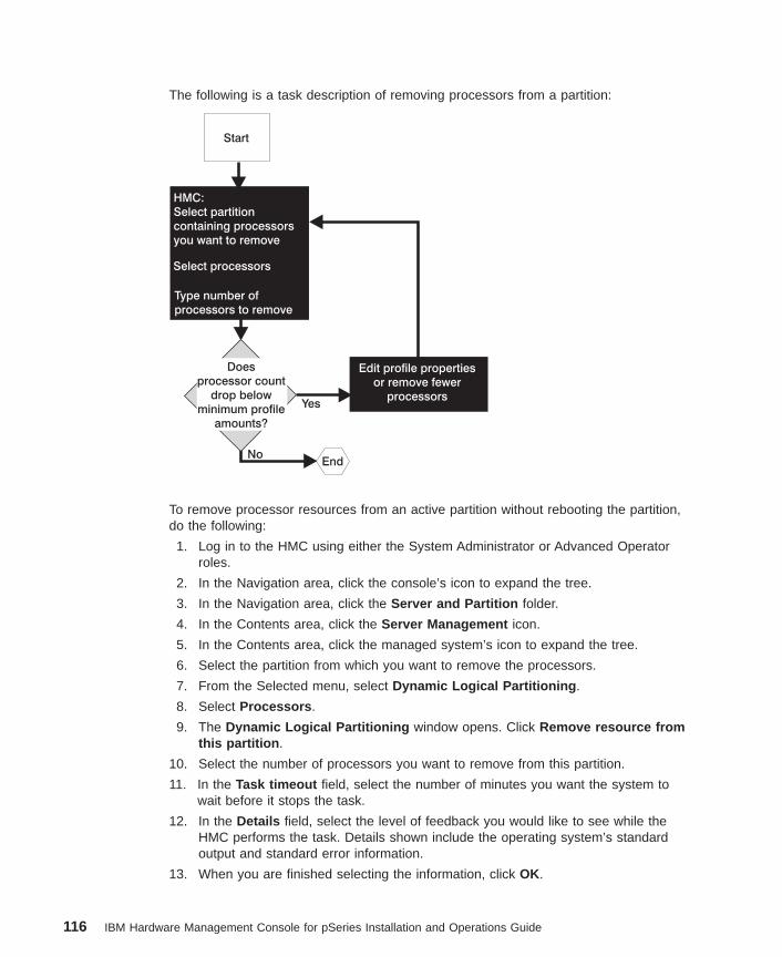
The following is a task description of removing processors from a partition:
Start
HMC:
Select partition
containing processors
you want to remove
Select processors
Type number of
processors to remove
No
Edit profile properties
or remove fewer
processorsYes
Does
processor count
drop below
minimum profile
amounts?
End
To remove processor resources from an active partition without rebooting the partition,do the following:
1. Log in to the HMC using either the System Administrator or Advanced Operatorroles.
2. In the Navigation area, click the console’s icon to expand the tree.
3. In the Navigation area, click the Server and Partition folder.
4. In the Contents area, click the Server Management icon.
5. In the Contents area, click the managed system’s icon to expand the tree.
6. Select the partition from which you want to remove the processors.
7. From the Selected menu, select Dynamic Logical Partitioning .
8. Select Processors .
9. The Dynamic Logical Partitioning window opens. Click Remove resource fromthis partition .
10. Select the number of processors you want to remove from this partition.
11. In the Task timeout field, select the number of minutes you want the system towait before it stops the task.
12. In the Details field, select the level of feedback you would like to see while theHMC performs the task. Details shown include the operating system’s standardoutput and standard error information.
13. When you are finished selecting the information, click OK.
116 IBM Hardware Management Console for pSeries Installation and Operations Guide
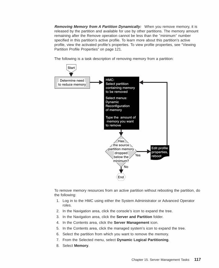
Removing Memory from A Partition Dynamically: When you remove memory, it isreleased by the partition and available for use by other partitions. The memory amountremaining after the Remove operation cannot be less than the ″minimum″ numberspecified in this partition’s active profile. To learn more about this partition’s activeprofile, view the activated profile’s properties. To view profile properties, see “ViewingPartition Profile Properties” on page 121.
The following is a task description of removing memory from a partition:
Start
End
Select menus:
Dynamic
Reconfiguration
of memory
Yes
No
Edit profile
properties,
reboot
HMC:
Select partition
containing memory
to be removed
Type the amount of
memory you want
to remove
Determine need
to reduce memory
Has
the source
partition memory
dropped
below the
minimum?
To remove memory resources from an active partition without rebooting the partition, dothe following:
1. Log in to the HMC using either the System Administrator or Advanced Operatorroles.
2. In the Navigation area, click the console’s icon to expand the tree.
3. In the Navigation area, click the Server and Partition folder.
4. In the Contents area, click the Server Management icon.
5. In the Contents area, click the managed system’s icon to expand the tree.
6. Select the partition from which you want to remove the memory.
7. From the Selected menu, select Dynamic Logical Partitioning .
8. Select Memory .
Chapter 15. Server Management Tasks 117
9. The Dynamic Logical Partitioning window opens. Click Remove resource fromthis partition .
10. Select the amount of memory you want to remove from this partition.
Note: If the Memory Information button appears in this window, the HMC hasdiscovered an inconsistency between any partition’s Allocated andRequested memory amounts. Click this button to correct the requestedmemory value and free memory resources to the system. For moreinformation about restoring memory, see “Restoring Memory Resources” onpage 231.
11. In the Task timeout field, select the number of minutes you want the system towait before it stops the task.
12. In the Details field, select the level of feedback you would like to see while theHMC performs the task. Details shown include the operating system’s standardoutput and standard error information.
13. When you are finished selecting the information, click OK.
Removing Adapters from A Partition Dynamically: This task allows you to removeI/O adapters from a partition without rebooting the partition’s operating system. Beforecontinuing with this task, you must use the partition’s operating system to manuallydeconfigure each adapter that you want to remove.
Note: Adapters designated as required in this partition’s active profile are not includedin this list and cannot be removed. To learn more about this partition’s activeprofile, view the activated profile’s properties.
To remove adapter resources from an active partition without rebooting the partition, dothe following:
1. Log in to the HMC using either the System Administrator or Advanced Operatorroles.
2. Make sure that this partition’s operating system is not currently using the adapter.For more information about determining if the operating system is using thisadapter, refer to the documentation provided with the partition’s operating system.
3. In the Navigation area, click the console’s icon to expand the tree.
4. In the Navigation area, click the Server and Partition folder.
5. In the Contents area, click the Server Management icon.
6. In the Contents area, click the managed system’s icon to expand the tree.
7. Select the partition from which you want to remove the adapters.
8. From the Selected menu, select Dynamic Logical Partitioning .
9. Select Adapters .
10. Select the adapters used by this partition that you want to remove.
11. The Dynamic Logical Partitioning window opens. Click Remove resource froma partition .
12. In the Task timeout field, select the number of minutes you want the system towait before it stops the task.
118 IBM Hardware Management Console for pSeries Installation and Operations Guide
13. In the Details field, select the level of feedback you would like to see while theHMC performs the task. Details shown include the operating system’s standardoutput and standard error information.
14. When you are finished selecting the information, click OK.
Deleting PartitionsTo delete a partition, the managed system must be powered on using the PartitionStandby power-on option. If you delete a partition, all of the profiles associated with thatpartition are also deleted. The partition is also automatically deleted from all systemprofiles.
You can delete partitions if you are a member of the System Administrator role.
Note: You cannot delete an activated partition.
To delete a partition, do the following:
1. Select the partition from the Contents area.
2. In the menu, click Selected .
3. Select Delete .
For information about deleting a partition profile, see “Deleting Partition Profiles” onpage 123.
Deleting Affinity PartitionsYou may only delete affinity partitions as a group; you may not delete them individually.
To delete a group of affinity partitions, you must be a member of one of the followingroles:
v System Administrator
v Advanced Operator
To delete a group of affinity partitions, do the following:
1. In the Contents area, select the affinity partition group you want to remove.
2. From the selected menu, select Affinity Logical Partition .
3. Select Delete .
4. After confirming that the affinity partitions listed are the ones you want to remove,click OK. The affinity partitions are removed from the Contents area.
Chapter 15. Server Management Tasks 119
Restarting the Operating SystemWhen a partition is running an operating system and the system hangs, use the HMC torestart the operating system.
Attention: This operation can corrupt data. Perform this procedure only after youhave attempted to restart the operating system manually.
Soft and Hard ResetsYou can perform either a ″hard″ and ″soft″ reset.
v Soft reset actions are determined by your operating system’s policy settings.Depending on how you have configured these settings, the operating system may:
– Perform a dump of system information
– Restart automatically
For more information about configuring your operating system’s policy settings, referto its supporting documentation.
v A hard reset acts as a virtual powering off of the system. Issuing a hard reset forcestermination and can corrupt information. Use this option only if the operating systemis disrupted and cannot send or receive commands.
To restart the operating system, you must be a member of one of the following roles:
v System Administrator
v Advanced Operator
v Service Representative
To restart the operating system you have installed on a partition, do the following:
1. In the Contents area, select the partition you want to reset.
2. In the menu, click Selected .
3. Select Operating System Reset .
4. Decide if you want a hard or soft reset. Select the appropriate check box and clickYes.
Managing Partition ProfilesA partition profile defines the set of resources that you need to create a partition. Youcan create more than one partition profile for a partition, but you can activate only onepartition profile for a partition at a time.
When you create a partition profile, the HMC shows you all the resources available onyour system. The HMC does not, however, check to see if another partition is currentlyusing a portion of these resources. For example, the HMC might show 16 processorson your system, but will not indicate that other partitions are using nine of them. Youcan conceivably create two partition profiles, each using a majority of system resources.However, you can do this only if you do not intend to use them at the same time. If youattempt to activate both of these partition profiles, the second activation attempt will fail.
120 IBM Hardware Management Console for pSeries Installation and Operations Guide
Creating Additional Partition ProfilesTo create partition profiles, you must be a member of one of the following roles:
v System Administrator
v Advanced Operator
To create a partition profile, do the following:
1. In the Contents area, select the partition for which you want to create a profile. Ifyou select the managed system, you create a new partition, not a profile.
2. In the menu, click Selected .
3. Select Create .
4. Select Profile from the menu. A profile creation wizard opens and guides youthrough the creation of a new profile.
You can now begin to assign resources to the new partition profile. This partition profiledoes not take effect until you use it to activate the partition.
Viewing Partition Profile PropertiesYou can view partition profile information from your HMC. Depending on your accesslevels, you can also restore, back up, and remove this data from the local file system.
Any user can view profile properties.
To view a partition profile’s properties, do the following:
1. In the Contents area, select the profile.
2. In the menu, click Selected .
3. Select Properties .
Setting Service AuthorityService representatives use the partition designated with service authority to performsystem firmware updates. If you set service authority for one partition, a servicerepresentative can use this partition to perform system updates without having to poweroff the managed system.
To set service authority, you must be a member of one of the following roles:
v Advanced Operator
v System Administrator
To set service authority, do the following:
1. In the Contents area, select the profile.
2. In the menu, click Selected .
3. Select Properties to open the Properties window.
4. Click the Other tab.
5. Click Set Service Authority .
6. Click OK.
Chapter 15. Server Management Tasks 121
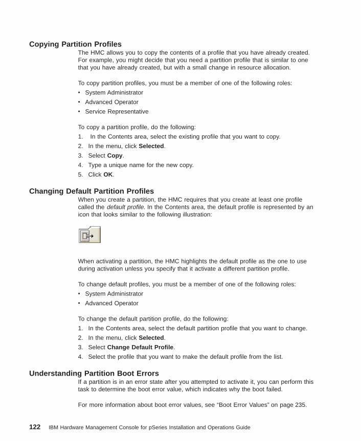
Copying Partition ProfilesThe HMC allows you to copy the contents of a profile that you have already created.For example, you might decide that you need a partition profile that is similar to onethat you have already created, but with a small change in resource allocation.
To copy partition profiles, you must be a member of one of the following roles:
v System Administrator
v Advanced Operator
v Service Representative
To copy a partition profile, do the following:
1. In the Contents area, select the existing profile that you want to copy.
2. In the menu, click Selected .
3. Select Copy .
4. Type a unique name for the new copy.
5. Click OK.
Changing Default Partition ProfilesWhen you create a partition, the HMC requires that you create at least one profilecalled the default profile. In the Contents area, the default profile is represented by anicon that looks similar to the following illustration:
When activating a partition, the HMC highlights the default profile as the one to useduring activation unless you specify that it activate a different partition profile.
To change default profiles, you must be a member of one of the following roles:
v System Administrator
v Advanced Operator
To change the default partition profile, do the following:
1. In the Contents area, select the default partition profile that you want to change.
2. In the menu, click Selected .
3. Select Change Default Profile .
4. Select the profile that you want to make the default profile from the list.
Understanding Partition Boot ErrorsIf a partition is in an error state after you attempted to activate it, you can perform thistask to determine the boot error value, which indicates why the boot failed.
For more information about boot error values, see “Boot Error Values” on page 235.
122 IBM Hardware Management Console for pSeries Installation and Operations Guide
To review a partition boot error, you must be a member of one of the following roles:
v System Administrator
v Advanced Operator
v Service Representative
To review a partition boot error, do the following:
1. In the Contents area, right-click the partition that is in the Error state.
2. Select Read Boot Error Value . A window opens that gives you more informationabout why the boot failed.
Deleting Partition ProfilesTo delete partition profiles, you must be a member of the System Administrator role.
To delete a partition profile, do the following:
1. In the Contents area, select the profile.
Note: Be sure to select the profile and not the partition itself, to avoid deleting anentire partition.
2. In the menu, click Selected .
3. Select Delete .
Managing System ProfilesSystem profiles are a collection of one or more partition profiles. When you activate asystem profile, you also activate each associated partition profile. You can use a systemprofile at any time, including when you power on the managed system.
For more information about partition profiles, see “Managing Partition Profiles” onpage 120.
Creating System ProfilesTo create system profiles, you must be a member of one of the following roles:
v System Administrator
v Advanced Operator
To create a system profile, do the following:
1. In the Contents area, select the managed system.
2. On the menu, click Selected .
3. Select Create .
4. Select System Profile .
5. Name the system profile and select the available partition profiles that you want toadd to the new system profile.
6. Click Add for each selected partition profile. Pick one profile per partition to placeinto a system profile.
Chapter 15. Server Management Tasks 123
7. Click OK.
Viewing System Profile PropertiesAny user can view system profile properties.
To view the properties of the system profile, do the following:
1. In the Contents area, select the system profile.
2. On the menu, click Selected .
3. Select Properties .
Modifying System Profile PropertiesTo modify system profiles, you must be a member of one of the following roles:
v System Administrator
v Advanced Operator
To modify system profiles, do the following:
1. In the Contents area, select the system profile you want to modify.
2. On the menu, click Selected .
3. Select Properties from the menu.
4. Change the system profile information as appropriate.
Copying System ProfilesBecause some system profiles are complex, the HMC allows you to copy the contentsof a profile you have already created.
To copy system profiles, you must be a member of one of the following roles:
v System Administrator
v Advanced Operator
To copy a system profile, do the following:
1. In the Contents area, select the existing profile that you want to copy.
2. On the HMC menu, click Selected .
3. Select Copy .
4. In the Copy Profile window, type the new profile name.
5. Click OK.
Deleting System ProfilesTo delete a system profile, you must be a member of the System Administrator role.
To remove a system profile, do the following:
1. In the Contents area, select the system profile.
2. On the menu, click Selected .
124 IBM Hardware Management Console for pSeries Installation and Operations Guide
3. Select Delete . The Delete System Profile window opens. Click Yes to delete theprofile.
Activating System ProfilesTo activate system profiles, you must be a member of one of the following roles:
v System Administrator
v Advanced Operator
v Operator
v Service Representative
To activate a system profile, do the following:
1. In the Contents area, select the system profile.
2. On the menu, click Selected .
3. Select Activate .
Validating That System Profiles Will Activate SuccessfullyIf one of the partition profiles in a system profile requires a resource that is currently inuse by the system or another partition, the system profile does not activate.
To validate system profiles, you must be a member of one of the following roles:
v System Administrator
v Advanced Operator
v Operator
v Service Representative
To ensure that a system profile will activate successfully, do the following:
1. In the Contents area, select the system profile.
2. On the menu, click Selected .
3. Select Validate .
If a situation exists that prevents the profile from activating successfully, a windowdisplays that provides you with the details.
Note: This validation is approximate, and depends on which part of the memory blockis being allocated to the current running partitions.
Activating System Profiles When Other Partition Profiles Are RunningTo activate a system profile, shut down the operating system for any active partition, sothat the partition’s state changes from Running to Ready.
Powering On Using a System ProfileYou can power on your managed system by using a predefined system profile. To learnmore about powering on using a system profile you have already created, read “SystemProfiles” on page 84.
Chapter 15. Server Management Tasks 125

126 IBM Hardware Management Console for pSeries Installation and Operations Guide
Chapter 16. Virtual Terminal Window
Because the physical serial ports on the managed system can only be assigned to onepartition, the virtual terminal implementation enables an AIX system console to beaccessed on logical partitions that have no physical serial port assigned. A telnetconnection directly to the partition is not sufficient, because AIX needs a console forrestarts, installations, and for some service functions.
One virtual terminal window is available for each partition. Likewise, one virtual terminalwindow is available for each managed system.
The communication link between the HMC and the managed system is an RS-232serial line running at 19,200 bits per second. All terminal sessions send and receivedata on this shared serial line.
The virtual console is a terminal with limited function. After you create a partition andconfigure its operating system, the typical operating system connection method isthrough a serial port, telnet, or rlogin. The virtual terminal is meant to be used forsupport and service. Performance cannot be guaranteed due to the limited bandwidth ofthe serial connection.
The virtual terminal supports the following:
v AIX system-management applications such as smitty .
v Other curses-driven applications.
v Standard POSIX line-discipline behaviors, so that applications that use serial ports donot need to be rewritten. However, some General Terminal Interface characteristicsare not applicable.
The virtual console terminal emulator emulates a vt320 terminal.
As a limited function terminal, the virtual terminal does not support the following:
v Printing to a virtual terminal
v Transparent print services
v Modem connection for the virtual console port
v Real-time applications
The tty that is configured on the AIX Virtual TTY Adapter is predefined as a vt320. Toset the terminal type on a virtual console session, use the following AIX command:
export TERM=vt320
127
Virtual Terminal Windows on a Full System PartitionFor a Full System Partition, the output of the S1 serial port is redirected, or wrapped tothe virtual console window. When the S1 serial port is wrapped, the output of anycommand is directed from the S1 serial port to the virtual console terminal. If you closethe virtual console window on the managed system, normal function is restored to theS1 serial port.
If a physical device is attached to the S1 serial port and that device is asserting theData Carrier Detect (DCD) signal, then the session on the S1 serial port does not wrapuntil the device is powered off or removed. Likewise, if the S1 port has been wrappedto the virtual console window and a device is attached to the S1 serial port, the virtualterminal must be closed to unwrap the S1 session.
When the managed system is in the No Power state, you can access the serviceprocessor configuration menus from this console session.
Opening a Virtual Terminal WindowTo open a virtual terminal window, you must be a member of one of the following roles:
v Operator
v Advanced Operator
v System Administrator
v Service Representative
You can have only one virtual terminal window per partition open at a time.
To open a virtual terminal window, do the following:
1. Click the plus sign (+) next to the managed system in the Contents area to expandthe tree.
2. Select a partition underneath the managed system.
3. Select Open Terminal Window . A virtual terminal window opens on your HMCdesktop.
Opening Virtual Terminal Windows on a PartitionOne terminal session is available for each defined partition. You can also open aterminal session for a managed system, but there is no interaction with the managedsystem after the partition has been powered to the Running state. The S1 serial port isnot wrapped when the managed system is partitioned.
A terminal window can be opened at any time, regardless of the state of the partition,similar to powering on or off a tty terminal. The virtual terminal window may be blankuntil the partition is activated.
128 IBM Hardware Management Console for pSeries Installation and Operations Guide
Managing AIX Device Drivers on PartitionsWhen you activate AIX in a partition, the operating system loads a device driver thatemulates a serial port device driver. AIX considers this device driver to be a serialdevice adapter. For example, the following command:
lsdev -C | grep sa
Returns output similar to the following:
LPAR Virtual Serial Adapter
A tty device is assigned to that adapter.
To install and boot, the AIX operating system requires a console window. Oninstallation, AIX prompts you to select a serial port from which to install. This portbecomes the default console port unless you change it.
One difference between the virtual terminal window device driver and a normal AIXconsole is that the virtual terminal window does not have to be opened in order to bootthe AIX operating system. You can boot all 16 partitions simultaneously without openinga virtual terminal window, provided that the profiles’ boot mode is set to Power OnNormal .
Installing AIX on a Full System PartitionIf you install AIX for a Full System Partition, select the S1 serial port as the console.The virtual terminal window device driver installs, but it does not load. If you thenchoose to boot the installed disk in a partition, one of the following may occur:
v If the S1 serial port is assigned to the partition you want to boot, the S1 serial portcontinues to have the AIX console assigned to it. If you open the virtual console port,the screen may remain blank, because no virtual terminal window device has beenenabled for that port.
To get a login to that port, use SMIT or Web-based System Manager to configureand enable a tty on the virtual terminal serial adapter. Another option is to assign thatport as the AIX console. The following AIX commands are helpful when assigning theport:
– The lcons command tells you which port the console is assigned to.
– The chcons command allows you to permanently switch the default console toanother serial port.
– The swcons command allows you to temporarily switch the console to anotherport.
v If the S1 serial port is not assigned to that partition, AIX recognizes the missingconsole and displays prompts on all valid console devices, including the virtualconsole driver. If no console is selected within 30 seconds, AIX continues to bootwithout a console. If the console prompt times out, the virtual terminal window mayremain blank until a console is defined.
Chapter 16. Virtual Terminal Window 129
Installing AIX on a PartitionIf you install AIX in a partition that has the native serial adapter as one of its resources,the installation terminal is the default AIX console. If the virtual terminal is the consoleand the disk is booted for a Full System Partition, the virtual console device driver is notloaded.
To install AIX on a partition, do the following:
1. Open a virtual terminal window on the managed system so the S1 serial port iswrapped to that terminal. Because the original console is now no longer available,you have 30 seconds to select the S1 port as your console. Otherwise, that portmay appear to hang.
2. Use the chcons command to change the console to avoid the 30-second timeout ifyou plan to use the Full System Partition with an operating system that wasinstalled in a logical partition.
If you install AIX in a partition that does not have the native serial adapters as one of itsresources, the device driver for the built-in serial adapter is not installed in that partition.AIX does not install device support for a physical device unless the device is present atthe time of installation. Do not attempt to boot that image as a Full System Partitionuntil you first install the correct device support.
The following steps describe one method of adding device support:
1. Add the native serial adapter and the CD device to your partition profile.
2. Boot the partition with the new resources.
3. Run the following command to add the device support:
cfgmgr -i /dev/cd0
Copying and Pasting Within a Virtual TerminalCopying and pasting is supported within a virtual terminal session only. To copy andpaste in a virtual terminal, do the following:
1. Use the mouse to draw a box around the text you want to copy.
2. Press and hold the Ctrl key and then press the Insert key to copy the text.
3. Press and hold the Shift key and then press the Insert key to paste the text.
For HMC Release 3, the cut and paste method for Xwindows works normally. To copy,hold down the left mouse button and highlight the text you want to copy. To paste,press the center mouse button. To paste using a 2-button mouse, click the left and rightbuttons simultaneously.
130 IBM Hardware Management Console for pSeries Installation and Operations Guide
Closing a Virtual Terminal WindowThere are two ways to close a virtual terminal. The preferred, usual method of closing aterminal window is to click on the X in the upper-right corner of the terminal window.This action removes the window from the HMC desktop and closes the connection. Anyuser can close a terminal window in this way.
You can also force a virtual terminal window to close in the following situations:
v The terminal is open on another HMC and you want to turn off that session.
v The terminal has been opened by another HMC.
To force a virtual terminal window to close you must be a member of one of thefollowing roles:
v Operator
v Advanced Operator
v System Administrator
v Service Representative
To force a terminal window to close, do the following:
1. Select the managed system from the Contents area.
2. Select Close Terminal .
Chapter 16. Virtual Terminal Window 131

132 IBM Hardware Management Console for pSeries Installation and Operations Guide
Chapter 17. Software Maintenance for the HMC and the Frame
The applications in the Software Maintenance folder allow you to do the following:
v Receive corrective service
v Install corrective service
v Back up critical console data
v Save upgrade data
v Format removable media
v Manage a frame of managed systems and resources
To open the Frame and HMC Software Maintenance applications, double-click theSoftware Maintenance icon in the Navigation area.
The Software Maintenance application contains the service tasks for a Frame ofmanaged systems and resources and the HMC. Use the Frame application to manageinstalled software to a Frame connected to the HMC. When you select the Frameapplication, you can receive and apply service from a diskette or from a remote system.The HMC application in the Software Maintenance folder allows you to manageinstalled HMC software.
Backing up Critical Console DataUsing your HMC, you can back up important data, such as the following:
v User-preference files
v User information
v HMC platform-configuration files
v HMC log files
The Backup Critical Console Data function saves the HMC data stored on your HMChard disk to the DVD-RAM and is critical to support HMC operations. Back up the HMCafter you have made changes to the HMC or to the information associated withpartitions.
To back up critical console data, you must be a member of one of the following roles:
v System Administrator
v Advanced Operator
v Operator
v Service Representative
To back up critical console data, do the following:
1. In the Navigation area, click the Software Maintenance icon.
2. In the Contents area, double-click the HMC icon.
3. In the Contents area, select Backup Critical Console Data .
133
4. Select Backup to store your critical console data on the DVD-RAM.
5. Click OK.
Saving Upgrade DataYou can store system information onto the HMC hard drive in preparation for an HMCupgrade.
Note: Only perform this task immediately prior to upgrading your HMC software fromone release to another. Any configuration changes made after performing thistask will not be migrated to the new HMC software release.
When you complete this process, the HMC saves configuration data that includes thefollowing:
v System preferences
v Profile information
v Service Agent files
v Inventory Scout Services files
To save upgrade data, you must be a member of one of the following roles:
v System Administrator
v Service Representative
v Advanced Operator
To save upgrade data to your HMC’s hard disk, do the following:
1. In the Navigation area, click the Software Maintenance icon.
2. In the Contents area, double-click the HMC icon.
3. In the Contents area, select Save Upgrade Data .
4. Select Save to hard drive and follow the onscreen instructions.
Installing Corrective Service for the HMCThis task allows you to update the level of code on the HMC. Corrective fixes areavailable through ftp and CD-ROM.
Note: Because the HMC is a closed system, you cannot install additional applicationson your Hardware Management Console. All the tasks you need to maintain themanaged system, the underlying operating system, and the HMC applicationcode are available by using the HMC’s management applications.
To install a corrective fix, you must be a member of one of the following roles:
v System Administrator
v Service Representative
To install a corrective fix, do the following:
134 IBM Hardware Management Console for pSeries Installation and Operations Guide
1. In the Navigation area, click the Software Maintenance icon.
2. In the Contents area, double-click the HMC icon.
3. In the Contents area, click Install Corrective Service . The Install CorrectiveService window opens.
4. Do one of the following:
If you have a corrective fix on removable media, insert the media in the appropriatedrive and click Apply corrective service from removable media .
OR
If you want to download the fix from a remote site and have the necessaryinformation from your support representative, click Download corrective servicefrom remote system, then apply downloaded service file . Then type the site,patch file, ID, and password information in the appropriate fields. This information isavailable from your support representative.
5. Click OK.
Formatting Removable MediaYou must format removable media before it can be used in the HMC.
To format removable media, you must be a member of one of the following roles:
v System Administrator
v Advanced Operator
v Operator
v Service Representative
To format removable media, do the following:
1. In the Navigation area, click the Software Maintenance icon.
2. In the Contents area, double-click the HMC icon.
3. In the Contents area, select Format Removable Media .
4. Insert the media, either diskette or DVD-RAM, into its appropriate drive.
5. Click Continue to format the media.
Receiving Corrective Service for the FrameThis task allows you to receive corrective service for the frame from either the HMC’sdiskette drive or by downloading the service from a remote site.
To receive a corrective service for the frame, you must be a member of one of thefollowing roles:
v System Administrator
v Service Representative
To receive a corrective fix, do the following:
1. In the Navigation area, open the Software Maintenance folder.
Chapter 17. Software Maintenance for the HMC and the Frame 135
2. In the Contents area, double-click the Frame icon. The Frame application opens inthe Contents area.
3. In the Contents area, click Receive Corrective Service . The Receive CorrectiveService window opens.
4. Do one of the following:
If you have a corrective fix on removable media, insert the media in the appropriatedrive and click Upload corrective service from diskette .
OR
If you want to download the fix from a remote site and have the necessaryinformation from your support representative, click Download corrective servicefrom remote system . Then type the site, patch file, ID, and password informationin the appropriate fields. This information is available from your supportrepresentative.
5. Click OK.
Installing Corrective Service on the FrameThis task allows you to update the level of code on the frame after you have received acorrective service. Corrective fixes are available through ftp and diskette.
Note: Because the HMC is a closed system, you cannot install additional applicationson your Hardware Management Console. All the tasks you need to maintain themanaged system, the underlying operating system, and the HMC applicationcode are available by using the HMC’s management applications.
To install a corrective fix on the frame, you must be a member of one of the followingroles:
v System Administrator
v Service Representative
To install a corrective fix, do the following:
1. In the Navigation area, open the Software Maintenance folder.
2. In the Contents area, double-click the Frame icon. The Frame application opens inthe Contents area.
3. In the Contents area, click Install Corrective Service . The Install CorrectiveService window opens.
4. Select the Corrective Service Version and select the Frame where the service willbe applied.
5. Click Install
6. Once the service has been applied, Click Cancel to return.
136 IBM Hardware Management Console for pSeries Installation and Operations Guide
Chapter 18. Service Agent
Service Agent (SA) accepts information from the Service Focal Point (SFP). It reportsserviceable events and associated data collected by SFP to IBM for serviceautomatically. The SA Gateway HMC maintains the database for all the SA data andevents sent to IBM, including any SA data from other Client HMCs.
This chapter provides an introduction to the Service Agent application. For a moredetailed description of configuring and using Service Agent, see the Electronic ServiceAgent for pSeries Hardware Management Console User’s Guide, available on the Webat the following location: ftp://ftp.software.ibm.com/aix/service_agent_code/7040HMC-SAUG.pdf .
To access the Service Agent application, click the Service Agent icon in the Navigationarea.
You can use Service agent to perform the following tasks:
v Report problems automatically; service calls are placed without intervention.
v Automatically send extended vital product data.
v Receive error notification automatically
v Support a networked environment with minimum telephone lines for modems
Any user can access Service Agent.
Overview of Service AgentYou can use the Service Agent application to define machines. After machines aredefined, they are registered with the IBM Service Agent Server (SAS). During theregistration process, an electronic key is created, which becomes part of your residentService Agent program. This key is used each time Service Agent places a call forservice. The IBM Service Agent Server verifies the current customer service status fromthe IBM entitlement database. If you are entitled for customer service, the service call isplaced.
Service Agent reports information to IBM to help with problem resolution. In somecases, this information may be used by IBM for other purposes. This informationconsists of the problem or error information itself, as well as Vital Product Data (VPD)or Inventory data.
In the event that the user is concerned about whether the information to be sent to IBMis sensitive, you can review the actual data by using either the Service Agent userinterface or from the command line using file display programs. If, after reviewing thedata and determining you do not want Service Agent to send data, you can use eitherof the following methods to prevent data from going to IBM.
v Within Service Agent, turn off the VPD gathering feature. This action prevents VPDfrom being gathered and sent to IBM.
137
OR
v After registering, turn off the modem itself and configure the Service AgentNotification process to use e-mail to notify a help desk or have the help desk monitorService Agent (in real time) using the Service Agent Alerts function. When ServiceAgent detects an error, you can then call IBM manually (instead of having ServiceAgent place the call).
For a more detailed description of configuring Service Agent, see the Electronic ServiceAgent for pSeries Hardware Management Console User’s Guide, available on the Webat the following location: ftp://ftp.software.ibm.com/aix/service_agent_code/7040HMC-SAUG.pdf .
Activating Service AgentThis section explains how to activate Service Agent.
Obtaining Service AgentService Agent for HMC is part of the HMC software and it comes either pre-installed, oris part of the recovery CD.
Activating Service Agent the First TimeService Agent processes are turned off on a new system or after recovery. On newinstalls, the HMC host name is a default name. You should assign a new HMC hostname to fit your network environment. For more information about setting host names,see “Setting Host Names” on page 43.
On the Change SA mode window for a gateway server, both the gateway and clienthost names should be the same. If the settings are for a client, the client host namematches the HMC host name. You must update the gateway host name to reflect theHMC SA gateway host. For more information about updating the gateway host name,see “Changing the Service Agent Mode” on page 141.
Use the Service Agent window for starting the processes when your account is ready tosupport SA. On the HMC gateway, ensure that the modem and phone are connectedproperly. If the HMC is configured as a client, start SA only after the network is set upproperly. Do not start SA processes if the network is not configured on the HMC. Formore information about setting up the network on the HMC, see “Customizing NetworkSettings” on page 40.
Any time you change the HMC host name, stop the SA application and change the SAmode to correct Service Agent’s host name settings. After you change the mode, youcan start the SA processes again. If this HMC was a client HMC, you must change theSA gateway database before starting the client SA to match the new client host name.
138 IBM Hardware Management Console for pSeries Installation and Operations Guide
Configuring and Using Service AgentThe Service Agent interface is divided vertically into two panes, a navigation pane onthe left and a detail viewing pane on the right.
The buttons at the top of the navigation pane are called category selectors. Eachcategory determines the type of information that is displayed in the detail window to theright. The two menu items File and Help are also near the top of the navigation pane.
The bottom of the navigation pane contains two buttons labeled Add and Delete . Thesebuttons are enabled, in Properties category view only, when they apply to the itemselected. For example, you cannot add or delete when the Error view category isselected. If you want to delete a machine, you must switch to the Properties categoryfirst.
For more information about how to use Service Agent, read the Electronic ServiceAgent for pSeries User’s Guide, available on the web atftp://ftp.software.ibm.com/aix/service_agent_code/7040HMC-SAUG.pdf.
Registering and Customizing the Service Agent User InterfaceTo start the Service Agent user interface, click Service Agent UI -Registration/Customization .
Any user role can use any SA task.
To make an HMC report to another gateway HMC, see “Changing the Service AgentMode” on page 141.
The first time you launch Service Agent from the Hardware Management Console(HMC), you must type contact information, configure the modem, and confirm thatService Agent is properly licensed. When you complete these tasks, Service Agent canproperly communicate with Service Focal Point and error warnings can be sent to theappropriate service technician.
To configure Service Agent on the HMC, do the following:
1. In the Navigation area, click the Service Applications icon.
2. In the Contents are, double click the Service Agent icon.
3. In the Contents area, click Service Agent Registration or Configuration .
4. The Password window opens. Type the default password provided with yourService Agent interface. The default password, which is case sensitive, is:
password
5. The License Agreement window opens. After reviewing the agreement, clickAccept .
6. Type your contact information. The following describes the information for eachfield (fields marked with an ! are required):
Name Contact that the support center asks for when making a service call.
Chapter 18. Service Agent 139
Phone NumberContact’s telephone number
Email AddressContact’s e-mail address
Country/RegionCountry or region from the pull down menu on right side of the entry
Type 4-digit machine type of the first managed system attached to this HMC
Serial Number7-digit serial number of the first managed system attached to this HMC
Model 3-digit model of the first managed system attached to this HMC
Use upper case for all alpha characters entered in the Type and Serial Numberfields. For a domestic United States machine serial numbers only, use 00 and thelast 5 digits of the managed system’s serial number.
7. Configure the modem. In the Navigation area, click the turnkey next to theNetwork icon.
8. In the Navigation area, click the turnkey next to the HMC host name that has themodem you want to configure.
9. In the Navigation area, click the Dialer icon.
10. In the Contents area, click the browser button and select your primary worklocation. The browse button is to the right of the location field. When you select aprimary location, the following fields are automatically completed with the requiredinformation:
Primary Phone Number
Account
User ID
Password
Primary Route
Note: You must correct the phone number for local calling standards. Remove the1-area code prefix if it is not needed. Add the 9 prefix, if it is necessary todial 9 to get to an outside line.
11. Select the appropriate modem from the list In the Baud Rate field. Select a baudrate of 38400.
12. Select the appropriate dial type in the Dial Type field.
13. Click OK. The modem is now configured.
14. Register your HMC with Service Agent and ensure that it is properly licensed. Inthe Navigation area, click the turnkey next to the Administration icon.
15. In the Navigation area, click the Register icon.
16. At the bottom or the Machines area, click Register . The Service AgentRegistration window opens.
17. Click Yes to connect to IBM.
18. A message window opens that prompts you to check the CallLog. Click OK.
140 IBM Hardware Management Console for pSeries Installation and Operations Guide
19. Check the CallLog to make sure that the information was sent. In the Navigationarea, click the CallLog icon. In the Contents area, review the status and ensurethat the information was sent.
20. Ensure that Service Agent is properly licensed. If Service Agent is not properlylicensed, it will not communicate properly with Service Focal Point. In theNavigation area, click the Network icon.
21. Above the Navigation area, click the lock icon. The lock icon represents theLicensing action.
22. In the Contents area, check the Status column to ensure that Service Agent isproperly licensed.
Stopping the Service Agent User InterfaceIf the user interface does not respond, you can close the Service Agent interface. Fromthe Service Agent user interface menu, select File and then Exit .
Any user role can stop the Service Agent user interface.
To stop the active Service Agent user interface, in the Contents area, click StopService Agent UI .
Starting Service Agent ProcessesWhen you activate the Service Agent processes, all other menu options become activeas well.
Any user role can start the Service Agent processes.
To start the Service Agent Processes, do the following:
1. In the Navigation area, click the Service Applications icon.
2. In the Contents area, double-click the Service Agent icon.
3. In the Contents area, click Start Service Agent Processes .
Changing the Service Agent ModeAn HMC can be configured to report to another HMC. When you change the ServiceAgent mode, the actual call home is performed through the second HMC, thereforenecessitating only one modem for a group of HMCs. Service Agent refers to the HMCwith a modem as a gateway and the HMCs reporting errors as Service Agent clients.
Any user role can change the Service Agent mode.
To change the Service Agent mode, do the following:
1. On the gateway HMC, open the Service Agent user interface. In the Navigationarea, click the Service Applications icon.
2. In the Contents area, double-click the Service Agent icon.
Chapter 18. Service Agent 141
3. In the Service Agent user interface, do the following:
a. Click the Network icon.
b. Click Add .
c. Select Child .
d. From the pop-up menu, select Machines .
e. Type the client information. In the Node Name window, type the followingdetails for the HMC that you want to set up as a client:
v Name: The IP name of the client HMC
v IP Address: The IP address of the client HMC
v Processor ID: The managed system’s ID (optional)
v Type: The 4 digit type of the first managed system connected to this HMC
v Serial No: The 7 digit serial number of the first managed system attached tothe HMC
v Model: The 3 digit model of the first managed system attached to this HMC
v Manufacturer: The name of the manufacturer of the managed system(optional)
4. On the client system, select Service Applications –> Service Agent –> ChangeService Agent Mode . The Change Service Agent Mode window opens.
5. Click the radio button next to client in the Change Service Agent Mode field.
6. Type the client and gateway IP names.
7. Click OK.
8. On the gateway HMC, verify that the client is reporting to the gateway.
9. In the Contents area, click the icon that looks like a lock. This is the LicenseStatus icon.
10. In the Contents area, look at the column under the heading Heartbeat . Ensure thatthis client has successfully contacted the gateway HMC. Also check the Licensecolumn to ensure that the client is properly licensed.
Stopping Service Agent ProcessesThis operation prevents all call-home functions.
Any user role can stop the Service Agent processes.
To stop all the Service Agent processes, do the following:
1. In the Navigation area, click the Service Applications icon.
2. In the Contents area, double-click the Service Agent icon.
3. In the Contents area, click Stop Service Agent Process .
Service Agent Status IndicatorsThe status section in the Contents area displays the current status of all Service Agentprocesses as follows:
142 IBM Hardware Management Console for pSeries Installation and Operations Guide
SA ModeIndicates whether the primary server is a gateway server or a client server.
Gateway MachineDisplays the name of the gateway machine. On a gateway machine, theprimary server and the client name are the same.
Secondary ServerDisplays the server you have configured to be the secondary server.
Tertiary ServerDisplays the server you have configured to be the tertiary server.
Client NameDisplays the name of the client and matches the node name that you enteredusing the Service Agent interface.
Service Agent StatusDisplays whether the Electronic Server System (ESS) or the On DemandServer (ODS) applications are currently running.
Chapter 18. Service Agent 143

144 IBM Hardware Management Console for pSeries Installation and Operations Guide

Chapter 19. Service Focal Point
This chapter provides information about using the Service Focal Point application.
Service representatives use the HMC as the starting point for all service issues. TheHMC groups various system management issues at one control point, allowing servicerepresentatives to use the Service Focal Point application to determine an appropriateservice strategy.
Traditional service strategies become more complicated in a partitioned environment.Each partition runs on its own, unaware that other partitions exist on the same system.If one partition reports an error for a shared resource, such as a managed systempower supply, other active partitions report the same error. The Service Focal Pointapplication enables service representatives to avoid long lists of repetitive call-homeinformation by recognizing that these errors repeat, and the filtering them into one errorcode.
Errors that require service are reported to the HMC as serviceable events. Because theHMC stores these serviceable events for 90 days and then discards them, it isimportant to have the partition and HMC date and time set correctly. For instance, if thedate on a partition’s software is set 90 days behind the HMC’s set time, the serviceableevents reported from this partition are immediately discarded. For more informationabout setting the HMC’s date and time, see “Setting and Viewing the Console Date andTime” on page 39. To set the partition’s date and time, see the documentation providedwith the operating system that is running on that partition.
Getting StartedWhen you are setting up Service Focal Point, keep the following in mind:
v If the time configured on a partition is 90 days older than time configured on theHMC, serviceable events cannot be reported.
v Verify that the HMC host names are defined. For more information on using fullyqualified and short host names, see “Setting Host Names” on page 43.
v If you need to add or change a partition name, see the “Assigning a Host Name toYour Partition” on page 27.
Testing Error ReportingTo ensure that Service Focal Point is configured properly, generate a test error by doingthe following:
1. In the partition, run diagnostics to test the managed system’s operator panel.
2. When the diagnostics window asks you if you see 0000 on the managed system’soperator panel, select NO. This action generates an error.
3. In the SRN window, type Enter to proceed.
4. When the system asks you if you want the error sent to Service Focal Point, selectYES.
145
5. Type F3 to exit diagnostics.
6. Wait for one minute while the managed system sends the error to Service FocalPoint.
7. Check the Serviceable Event window to ensure that the error was sent to ServiceFocal Point and that Service Focal Point reported the error. For more informationabout working with serviceable events, see “Working With Serviceable Events” onpage 148.
Service Focal Point SettingsThe Service Focal Point Settings task in the Contents area allows you to configure yourHMC’s Service Focal Point application.
Note: The Advanced Operator, Operator and Viewer roles have read-only access to thefollowing tasks.
Automatic Call-Home FeatureYou can configure the HMC to automatically call an appropriate service center when itidentifies a serviceable event.
To enable or disable the call-home feature, you must be a member of one of thefollowing roles:
v System Administrator
v Service Representative
To enable or disable the call-home feature for one or more systems, do the following:
Note: It is strongly recommended that you not disable the call-home feature. When youdisable the call-home feature, serviceable events are not automatically reportedto your service representative.
1. In the Navigation area, click the Service Applications icon.
2. In the Navigation area, double-click the Service Focal Point icon.
3. In the Contents area, click Service Focal Point Settings .
4. The Service Focal Point Settings window opens. Select the CEC Call Home tab onthe top of the window.
5. Click on the managed system you want to enable or disable.
6. Click Enable to enable call-home for the selected system, or click Disable todisable call-home for the selected system.
7. Click OK.
Setting Up SurveillanceService Focal Point surveillance generates serviceable events when it detectscommunication problems between the HMC and its managed systems.
You can configure how you want the HMC to survey the following:
146 IBM Hardware Management Console for pSeries Installation and Operations Guide

v The number of disconnected minutes considered an outage
v The number of connected minutes you want the HMC to consider a recovery
v The number of minutes between outages considered a new incident
To set up surveillance, you must be a member of one of the following roles:
v System Administrator
v Service Representative
To set up surveillance, do the following:
1. In the Navigation area, click the Service Applications icon.
2. In the Navigation area, double-click the Service Focal Point icon.
3. In the Contents area, select Service Focal Point Settings .
4. The Service Focal Point Settings window opens. Select the Surveillance Setup tabon the top of the window.
5. In the first field, select the number of minutes you want the HMC to wait beforesending a disconnection error message.
6. In the second field, select the amount of connection time that the HMC isconsidered to be recovered. This amount is expressed in minutes.
7. In the third field, select the number of minutes between outages that you want theHMC to wait before sending a new incident report.
8. Select one or more managed systems from the table in the lower part of the windowand then click Enable or Disable . Surveillance is then either enabled or disabled forthe selected managed systems.
Enabling Surveillance NotificationsYou can enable or disable surveillance-error notification from this HMC to connectedmanaged systems. Enabling this notification causes errors to be passed to the ServiceAgent application for notification.
Note: You must further configure Service Agent to handle notifications sent by ServiceFocal Point. For more information about Service Agent, see Chapter 18, “ServiceAgent” on page 137.
To set up surveillance, you must be a member of one of the following roles:
v System Administrator
v Service Representative
To set up surveillance-error notification, do the following:
1. In the Navigation area, click the Service Applications icon.
2. In the Navigation area, double-click the Service Focal Point icon.
3. In the Contents area, select Service Focal Point Settings .
4. The Service Focal Point Settings window opens. Select the SurveillanceNotification tab on the top of the window.
Chapter 19. Service Focal Point 147
5. Select one or more managed systems from the list and then click Enable orDisable . Surveillance notification is then either enabled or disabled for the selectedmanaged systems.
Working With Serviceable EventsYou can view, add, or update serviceable event information, including error details.
Viewing Serviceable EventsTo view serviceable events, you must be a member of one of the following roles:
v System Administrator
v Service Representative
v Advanced Operator
v Operator
v Viewer
To view a serviceable event, do the following:
1. In the Navigation area, click the Service Applications icon.
2. In the Navigation area, double-click the Service Focal Point icon.
3. In the Contents area, click Select Serviceable Event .
4. Designate the set of serviceable events you want to view. When you are finished,click OK.
5. The Serviceable Event Overview window opens, and the entries displayed areordered by time stamp. Each line in the Serviceable Event Overview windowcorresponds to one error within a serviceable event. On this window, designate theset of serviceable events you want to view by specifying your search criteria (suchas event status or error class).
Note: Only events that match all of the criteria that you specify are shown.When you are finished, click OK.
When you select a line in the Serviceable Event Overview window, all lines in the sameserviceable event are selected. To open the Serviceable Event Details window for theselected event, select the event and click Event Details .
Viewing Serviceable Event DetailsTo view serviceable event details, do the following:
1. Perform the steps in “Viewing Serviceable Events”.
2. The Serviceable Event Details window opens, showing extended serviceable eventinformation, including the following:
v Status
v Earliest original time stamp of any managed object
v AIX error log
v Should this error ever get called home?
148 IBM Hardware Management Console for pSeries Installation and Operations Guide
v Error was called home
v Pointer to extended error-data collection on the HMC
The window’s lower table displays all of the errors associated with the selectedserviceable event. The information is shown in the following sequence:
v Failing device system name
v Failing device machine type/model/serial
v Error class
v Descriptive error text
Viewing Serviceable Event Error DetailsTo view serviceable event error details, do the following:
1. Perform the steps in “Viewing Serviceable Event Details” on page 148.
2. Select an error in the lower table, and click Error Details .
Viewing Service Processor Error DetailsTo view service processor error details, do the following:
1. Perform the steps in “Viewing Serviceable Event Error Details”.
2. If the serviceable event error details you are viewing are for a serviceprocessor-class error, the lower table on the resulting window contains serviceprocessor errors. Select a service processor error from the lower table, and clickService Processor Error Details to see further details.
Saving and Managing Extended Error DataTo save extended error (EE) data, do the following:
1. Perform the steps in “Viewing Serviceable Event Details” on page 148.
2. Click Save EE Data . To save extended error data for only one error associated withthe serviceable event (rather than for the entire serviceable event), select the errorfrom the lower table and then click Error Details . In the next menu, click ManageEE Data.
Viewing and Adding Serviceable Event CommentsTo add comments to a serviceable event, you must be a member of the ServiceRepresentative role.
To add comments to a serviceable event, do the following:
Note: You cannot edit or delete previous comments.
1. Perform the steps in “Viewing Serviceable Event Details” on page 148.
2. Select the error to which you want to add comments to and click Comments... . Ifyou want to close the event and add comments, click Close Event from thiswindow. The Serviceable Event Comments window opens.
3. Type your name and add comments as appropriate. You can also review previouscomments, but you cannot edit this information.
Chapter 19. Service Focal Point 149
4. If you clicked Comments on the Serviceable Event Details window, clicking OKcommits your entry and returns you to the Serviceable Event Details window.
If you clicked Close Event on the Serviceable Event Details window, clicking OKcommits all changes and opens the Update FRU Information window. For moreinformation about updating field replaceable unit information, see “Updating FieldReplaceable Unit (FRU) Information”.
Closing a Serviceable EventTo close a serviceable event, do the following:
1. Perform the steps in “Viewing Serviceable Event Details” on page 148.
2. Select the error to which you want to add comments and click Comments... .
3. Click Close Event from this window. The Serviceable Event Comments windowopens.
4. Click OK to commit your comments. The Update FRU Information windowdisplays. See “Updating Field Replaceable Unit (FRU) Information” for informationon completing this window. Click OK on the Update FRU Information window toclose the serviceable event.
Note: You must close a serviceable event after it has been serviced to ensure thatif a similar error is reported later, it is called home. If an old problem remainsopen, the new similar problem is reported as a duplicate. Duplicate errors areneither reported nor called home to a service center. Close a serviceableevent when the partition that reports the error is active. Closing the eventcauses the new status of the serviceable event to be properly sent to thepartition.
Updating Field Replaceable Unit (FRU) InformationThis task allows you to update the FRU information you changed or modified as a resultof this serviceable event. From this panel, you can also activate and deactivate LEDsand search for other serviceable events that contain the same FRU entries.
To update FRU information, do the following:
1. Perform the steps in “Viewing Serviceable Event Details” on page 148.
2. Click FRU Information... . The Update FRU Information window opens.
The lower table shows any parts that you have replaced or added during yourcurrent update session but that have not been committed to the serviceable event.The changes from the lower table are committed by clicking OK or Apply .
From this window, you can also activate and deactivate LEDs and search for otherServiceable Events that contain the same FRU entries.
Replacing an Existing FRUTo replace a part already listed for this serviceable event, do the following:
1. Perform the steps in “Updating Field Replaceable Unit (FRU) Information”.
2. In the upper table, double-click the part you want to replace.
150 IBM Hardware Management Console for pSeries Installation and Operations Guide
3. If the FRU has a new part number, type it in the New FRU Part Number field.
4. Click Replace FRU . The Update FRU Information window displays the FRUreplacement information in the lower table. Click OK or Apply to commit thechanges to the serviceable event.
Adding a New FRUYou can add a part to the serviceable event that was not listed in the upper table of theUpdate FRU Information window. To add a new FRU for this serviceable event, do thefollowing:
1. Perform the steps in “Updating Field Replaceable Unit (FRU) Information” onpage 150.
2. Click Add New FRU to List .
3. Type the FRU’s location code and its part number in the appropriate fields.
4. Click Add to List . The Update FRU Information window opens and displays thenewly added FRU in the lower table.
5. Click OK or Apply to commit these changes to the serviceable event.
Note: After you click OK or Apply , you cannot change this information. If youclicked the Close Event button in the Serviceable Event Details window,then clicking OK also completes the close dialog and changes the status ofthe serviceable event to Closed.
Viewing Serviceable Event Partition InformationYou can view partition information associated with this serviceable event. Thisinformation includes each affected partition’s state and resource use.
1. Perform the steps in “Viewing Serviceable Event Details” on page 148.
2. Click Partition Info... .
Hardware Service Functions
Activating and Deactivating FRU Identity LEDsThis task allows you to activate or deactivate a managed system’s system attentionLED or any FRU identity LED. FRU identity LEDs are helpful in determining whichFRUs need servicing.
To activate or deactivate a managed system’s System Attention LED, do the following:
1. In the Navigation area, click the Service Applications icon.
2. In the Navigation area, double-click the Service Focal Point icon.
3. In the Contents area, select Hardware Service Functions . The LED Managementwindow opens.
4. In the LED Management window, select one or more managed systems from thetable.
5. Select either Activate LED or Deactivate LED . The associated System AttentionLED is then either turned on or off.
Chapter 19. Service Focal Point 151
To activate or deactivate a FRU associated with a particular managed system, do thefollowing:
1. In the Navigation area, click the Service Applications icon.
2. In the Navigation area, double-click the Service Focal Point icon.
3. In the Contents area, click Hardware Service Functions . The LED Managementwindow opens.
4. In the LED Management window, select one managed system from the table.
5. Click the List FRUs... button. The list of FRU slot indices and their respectivecurrent LED states display.
6. Select one or more FRU slot indexes.
7. Click either the Activate LED or the Deactivate LED button.
The associated FRU Identity LEDs are now either enabled (blinking) or off.
152 IBM Hardware Management Console for pSeries Installation and Operations Guide
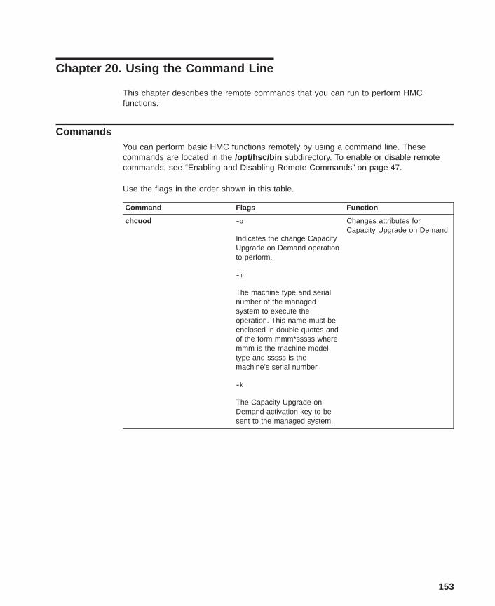
Chapter 20. Using the Command Line
This chapter describes the remote commands that you can run to perform HMCfunctions.
CommandsYou can perform basic HMC functions remotely by using a command line. Thesecommands are located in the /opt/hsc/bin subdirectory. To enable or disable remotecommands, see “Enabling and Disabling Remote Commands” on page 47.
Use the flags in the order shown in this table.
Command Flags Function
chcuod -o
Indicates the change CapacityUpgrade on Demand operationto perform.
-m
The machine type and serialnumber of the managedsystem to execute theoperation. This name must beenclosed in double quotes andof the form mmm*sssss wheremmm is the machine modeltype and sssss is themachine’s serial number.
-k
The Capacity Upgrade onDemand activation key to besent to the managed system.
Changes attributes forCapacity Upgrade on Demand
153
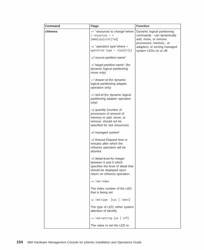
Command Flags Function
chhwres -r ″resources to change″where< resources = <[mem|cpu|slot|led]
-o ″operation type″where <operation type = <[a|m|r|s]
-p″source-partition-name″
-t″target-partition-name″ (fordynamic logical partitioningmove only)
-i″drawer-id (for dynamiclogical partitioning adapteroperation only)
-s″slot-id (for dynamic logicalpartitioning adapter operationonly)
-q″quantity (number ofprocessors of amount ofmemory to add, move, orremove; should not bespecified for slot resources)
-m″managed system″
-w″timeout Elapsed time inminutes after which thechhwres operation will beaborted
-d″detail-level An integerbetween 0 and 5 whichspecifies the level of detail thatshould be displayed uponreturn on chhwres operation.
-x led-index
The index number of the LEDthat is being set
-y led-type [sys | ident]
The type of LED; either systemattention of identify
-v led-setting [on | off]
The value to set the LED to
Dynamic logical partitioningcommands - can dynamicallyadd, move, or removeprocessors, memory , oradapters; or turning managedsystem LEDs on or off.
154 IBM Hardware Management Console for pSeries Installation and Operations Guide
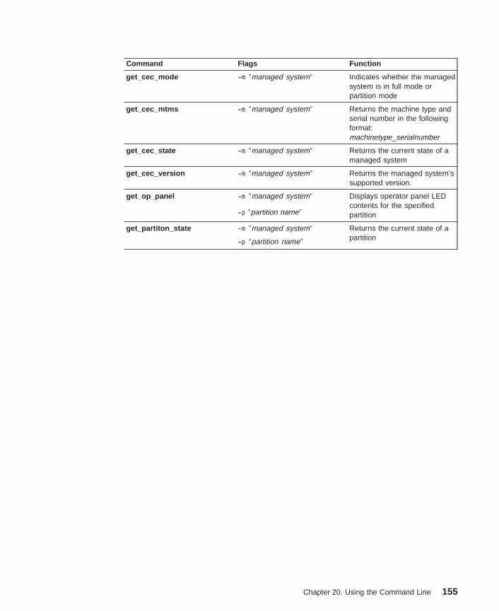
Command Flags Function
get_cec_mode -m ″managed system″ Indicates whether the managedsystem is in full mode orpartition mode
get_cec_mtms -m ″managed system″ Returns the machine type andserial number in the followingformat:machinetype_serialnumber
get_cec_state -m ″managed system″ Returns the current state of amanaged system
get_cec_version -m ″managed system″ Returns the managed system’ssupported version.
get_op_panel -m ″managed system″ Displays operator panel LEDcontents for the specifiedpartition-p ″partition name″
get_partiton_state -m ″managed system″ Returns the current state of apartition-p ″partition name″
Chapter 20. Using the Command Line 155
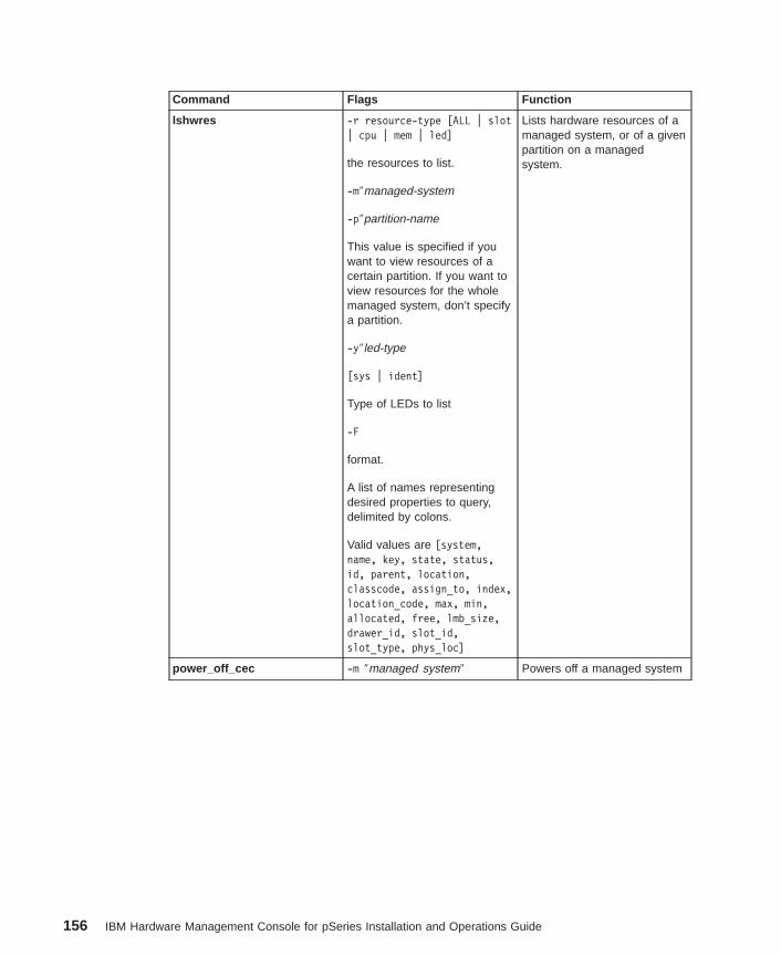
Command Flags Function
lshwres -r resource-type [ALL | slot| cpu | mem | led]
the resources to list.
-m″managed-system
-p″partition-name
This value is specified if youwant to view resources of acertain partition. If you want toview resources for the wholemanaged system, don’t specifya partition.
-y″led-type
[sys | ident]
Type of LEDs to list
-F
format.
A list of names representingdesired properties to query,delimited by colons.
Valid values are [system,name, key, state, status,id, parent, location,classcode, assign_to, index,location_code, max, min,allocated, free, lmb_size,drawer_id, slot_id,slot_type, phys_loc]
Lists hardware resources of amanaged system, or of a givenpartition on a managedsystem.
power_off_cec -m ″managed system″ Powers off a managed system
156 IBM Hardware Management Console for pSeries Installation and Operations Guide
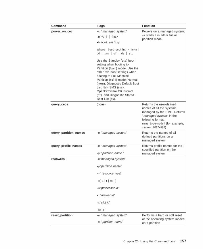
Command Flags Function
power_on_cec -c ″managed system″ Powers on a managed system;-m starts it in either full orpartition mode.
-m full | lpar
-b boot setting
where boot setting = norm |dd | sms | of | ds | std
Use the Standby (std) bootsetting when booting toPartition (lpar) mode. Use theother five boot settings whenbooting to Full MachinePartition (full) mode: Normal(norm), Diagnostic Default BootList (dd), SMS (sms),OpenFirmware OK Prompt(of), and Diagnostic StoredBoot List (ds).
query_cecs (none) Returns the user-definednames of all the systemsmanaged by the HMC. Returns″managed system″ in thefollowing format,name_type-model (for example,server_7017–S90)
query_partition_names -m ″managed system″ Returns the names of alldefined partitions on amanaged system
query_profile_names -m ″managed system″
-p ″partition name ″
Returns profile names for thespecified partition on themanaged system
rechwres -m″managed-system
-p″partition name″
-r[ resource type]
-o[ a | r | m | ]
-u″processor id″
-i″drawer id″
-s″slot id″
-help
reset_partition -m ″managed system″ Performs a hard or soft resetof the operating system loadedon a partition-p ″partition name″
Chapter 20. Using the Command Line 157
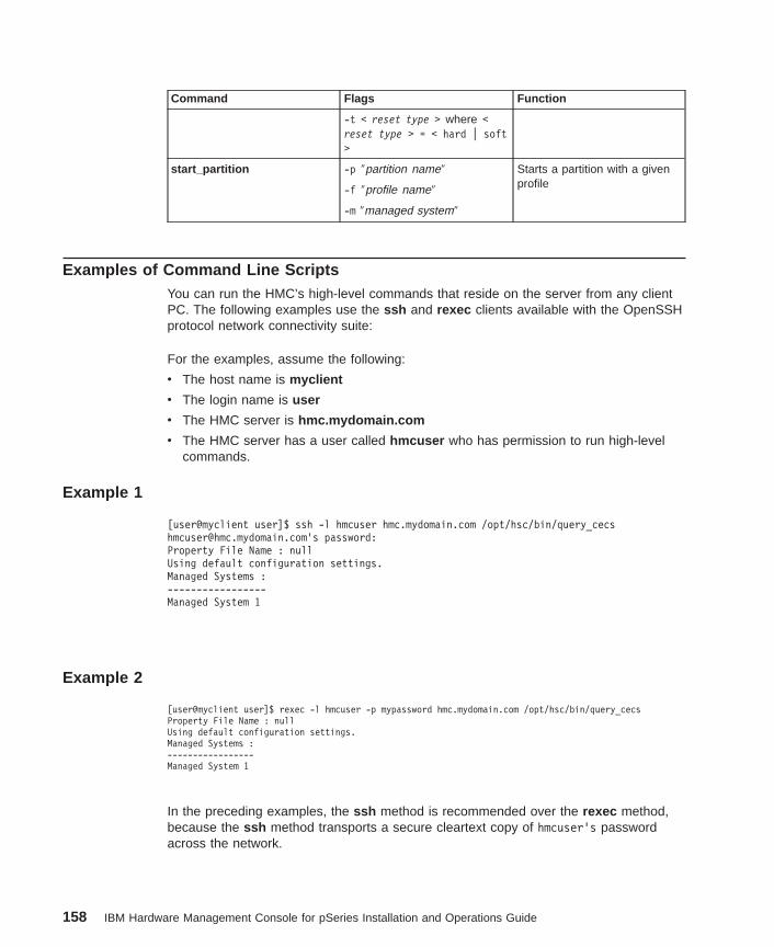
Command Flags Function
-t < reset type > where <reset type > = < hard | soft>
start_partition -p ″partition name″ Starts a partition with a givenprofile-f ″profile name″
-m ″managed system″
Examples of Command Line ScriptsYou can run the HMC’s high-level commands that reside on the server from any clientPC. The following examples use the ssh and rexec clients available with the OpenSSHprotocol network connectivity suite:
For the examples, assume the following:
v The host name is myclient
v The login name is user
v The HMC server is hmc.mydomain.com
v The HMC server has a user called hmcuser who has permission to run high-levelcommands.
Example 1
[user@myclient user]$ ssh -l hmcuser hmc.mydomain.com /opt/hsc/bin/[email protected]’s password:Property File Name : nullUsing default configuration settings.Managed Systems :-----------------Managed System 1
Example 2
[user@myclient user]$ rexec -l hmcuser -p mypassword hmc.mydomain.com /opt/hsc/bin/query_cecsProperty File Name : nullUsing default configuration settings.Managed Systems :-----------------Managed System 1
In the preceding examples, the ssh method is recommended over the rexec method,because the ssh method transports a secure cleartext copy of hmcuser’s passwordacross the network.
158 IBM Hardware Management Console for pSeries Installation and Operations Guide
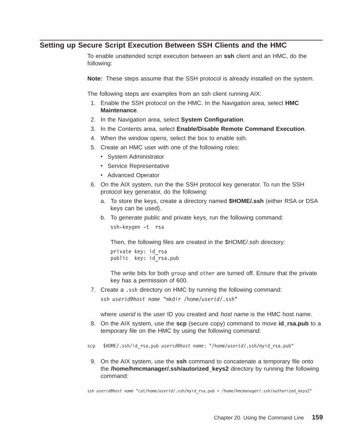
Setting up Secure Script Execution Between SSH Clients and the HMCTo enable unattended script execution between an ssh client and an HMC, do thefollowing:
Note: These steps assume that the SSH protocol is already installed on the system.
The following steps are examples from an ssh client running AIX:
1. Enable the SSH protocol on the HMC. In the Navigation area, select HMCMaintenance .
2. In the Navigation area, select System Configuration .
3. In the Contents area, select Enable/Disable Remote Command Execution .
4. When the window opens, select the box to enable ssh.
5. Create an HMC user with one of the following roles:
v System Administrator
v Service Representative
v Advanced Operator
6. On the AIX system, run the the SSH protocol key generator. To run the SSHprotocol key generator, do the following:
a. To store the keys, create a directory named $HOME/.ssh (either RSA or DSAkeys can be used).
b. To generate public and private keys, run the following command:
ssh-keygen -t rsa
Then, the following files are created in the $HOME/.ssh directory:
private key: id_rsapublic key: id_rsa.pub
The write bits for both group and other are turned off. Ensure that the privatekey has a permission of 600.
7. Create a .ssh directory on HMC by running the following command:
ssh userid@host name "mkdir /home/userid/.ssh"
where userid is the user ID you created and host name is the HMC host name.
8. On the AIX system, use the scp (secure copy) command to move id_rsa.pub to atemporary file on the HMC by using the following command:
scp $HOME/.ssh/id_rsa.pub userid@host name: "/home/userid/.ssh/myid_rsa.pub"
9. On the AIX system, use the ssh command to concatenate a temporary file ontothe /home/hmcmanager/.ssh/autorized_keys2 directory by running the followingcommand:
ssh userid@host name "cat/home/userid/.ssh/myid_rsa.pub > /home/hmcmanager/.ssh/authorized_keys2"
Chapter 20. Using the Command Line 159

10. Use the ssh command to remove the temporary file on HMC by running thefollowing command:
ssh userid@host name "rm /home/userid/.ssh/myid_rsa.pub"
Deleting the Key from the HMCTo delete the key from the HMC, do the following:
1. On AIX partition, use the scp command to copy the authorized_keys2 file from theHMC to the AIX partition.
scp userid@host name :.ssh/authorized_keys2 /tmp/mykeyfile"
2. Edit the /tmp/mykeyfile file and remove the line containing the key and host namethat you want to disable password prompting when remotely executing HMCcommand with ssh .
3. On an AIX partition, use the scp command to copy the new file over to the HMC byusing the following command:
scp /tmp/mykeyfile userid@host name ".ssh/authorized_keys2"
4. If you want to enable password prompting for all hosts accessing the HMC via ssh ,use the following ssh command to remove the key file from the HMC:
ssh userid@host name "rm ./ssh/authorized_keys2"
160 IBM Hardware Management Console for pSeries Installation and Operations Guide
Appendix A. Notices
This information was developed for products and services offered in the U.S.A.
The manufacturer may not offer the products, services, or features discussed in thisdocument in other countries. Consult the manufacturer’s representative for informationon the products and services currently available in your area. Any reference to themanufacturer’s product, program, or service is not intended to state or imply that onlythat product, program, or service may be used. Any functionally equivalent product,program, or service that does not infringe any intellectual property right of themanufacturer may be used instead. However, it is the user’s responsibility to evaluateand verify the operation of any product, program, or service.
The manufacturer may have patents or pending patent applications covering subjectmatter described in this document. The furnishing of this document does not give youany license to these patents. You can send license inquiries, in writing, to themanufacturer.
The following paragraph does not apply to the United Kingdom or any countrywhere such provisions are inconsistent with local law: THIS MANUAL ISPROVIDED ″AS IS″ WITHOUT WARRANTY OF ANY KIND, EITHER EXPRESSED ORIMPLIED, INCLUDING, BUT NOT LIMITED TO, THE IMPLIED WARRANTIES OFNON-INFRINGEMENT, MERCHANTABILITY OR FITNESS FOR A PARTICULARPURPOSE. Some states do not allow disclaimer of express or implied warranties incertain transactions; therefore, this statement may not apply to you.
This information could include technical inaccuracies or typographical errors. Changesare periodically made to the information herein; these changes will be incorporated innew editions of the publication. The manufacturer may make improvements and/orchanges in the product(s) and/or the program(s) described in this publication at anytime without notice.
Information concerning products made by other than the manufacturer was obtainedfrom the suppliers of those products, their published announcements, or other publiclyavailable sources. The manufacturer has not tested those products and cannot confirmthe accuracy of performance, compatibility or any other claims related to products madeby other than the manufacturer. Questions on the capabilities of products made by otherthan the manufacturer should be addressed to the suppliers of those products.
161

162 IBM Hardware Management Console for pSeries Installation and Operations Guide
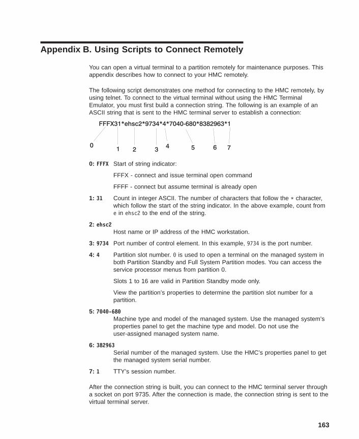
Appendix B. Using Scripts to Connect Remotely
You can open a virtual terminal to a partition remotely for maintenance purposes. Thisappendix describes how to connect to your HMC remotely.
The following script demonstrates one method for connecting to the HMC remotely, byusing telnet. To connect to the virtual terminal without using the HMC TerminalEmulator, you must first build a connection string. The following is an example of anASCII string that is sent to the HMC terminal server to establish a connection:
0: FFFX Start of string indicator:
FFFX - connect and issue terminal open command
FFFF - connect but assume terminal is already open
1: 31 Count in integer ASCII. The number of characters that follow the * character,which follow the start of the string indicator. In the above example, count frome in ehsc2 to the end of the string.
2: ehsc2Host name or IP address of the HMC workstation.
3: 9734 Port number of control element. In this example, 9734 is the port number.
4: 4 Partition slot number. 0 is used to open a terminal on the managed system inboth Partition Standby and Full System Partition modes. You can access theservice processor menus from partition 0.
Slots 1 to 16 are valid in Partition Standby mode only.
View the partition’s properties to determine the partition slot number for apartition.
5: 7040-680Machine type and model of the managed system. Use the managed system’sproperties panel to get the machine type and model. Do not use theuser-assigned managed system name.
6: 382963Serial number of the managed system. Use the HMC’s properties panel to getthe managed system serial number.
7: 1 TTY’s session number.
After the connection string is built, you can connect to the HMC terminal server througha socket on port 9735. After the connection is made, the connection string is sent to thevirtual terminal server.
163
You must set the telnet mode to character. To write the ctrl ] character into a script,you must use the sequence ctrl v ctrl ].
To end the session, do one of the following:
v Press ctrl ]
OR
v Click Telnet and then select quit .
This action runs the following script:
script_name hostname port partition machine_type/model*serial session_id
where:
v hostname = host name of the HMC
v port = fixed at 9734
v partition = the ID of the partition, ranging from 000 to 016
The following example shows how you can use a script to connect to a remote system:
#!/usr/bin/expect -f
system "echo [string length $argv]"system "echo [lindex $argv 0]"system "echo [lindex $argv 1]"system "echo [lindex $argv 2]"system "echo [lindex $argv 3]"system "echo [lindex $argv 4]"
spawn telnet [lindex $argv 0] 9735
expect "Escape"
# Note that the \r is not included in the send countsend -- "FFFX[string length $argv]*[lindex $argv 0]*[lindex $argv 1]*[lindex $argv 2]*[lindex $argv 3]*[lindex $argv 4]\r"
sleep .5
# note: enter ^] using the sequence ctrl v ctrl ] on a unix system.send -- "^]\r"
sleep .5
expect "telnet"
send -- "mode character\r"
interact
164 IBM Hardware Management Console for pSeries Installation and Operations Guide
Appendix C. Error Messages and Recovery Information
The following tables contain information about error messages that can be displayed bythe HMC during system configuration and operations.
Use this appendix to learn more about a specific error or information message. Thetable also includes recovery information (if applicable) to help you determine a recoverystrategy.
Console EventsError Codes
Message Recovery Action
HSCE2066 A scheduled backup of criticalconsole data failed with a return codeof {0}.
The possible return code values are:
v 4 - A return code of 4 indicates theremovable media could not bemounted.
Recovery Action - Verify that themedia is inserted properly in thedrive and try the operation again.
v 5 - A return code of 5 indicatesthat the removable media is writeprotected.
Recovery Action - Remove thewrite protection and try theoperation again.
v Any value except 4 or 5 is anInternal HMC Error
Recovery Action:
1. Perform Backup Critical Datatask.
2. Call for HMC software support.
Inventory ScoutError Codes
Message Recovery Action
HSCI0100 No managed systems were detectedthat are attached to this systemconsole.
None
HSCI0101 No partitions have been defined forthis managed system.
None
HSCI0102 A blank or invalid entry was enteredin the partition password field.
Enter a valid password value.
HSCI0103 A blank or invalid entry was enteredin the listening port field.
Enter a valid port value.
HSCI0104 A blank or invalid entry was enteredin the IP address field.
Enter a valid IP address value.
HSCI0110 The Inventory Scout commandcompleted successfully.
None
165
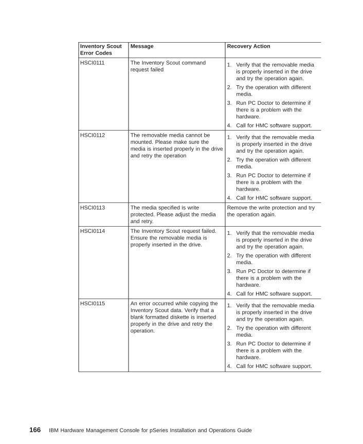
Inventory ScoutError Codes
Message Recovery Action
HSCI0111 The Inventory Scout commandrequest failed
1. Verify that the removable mediais properly inserted in the driveand try the operation again.
2. Try the operation with differentmedia.
3. Run PC Doctor to determine ifthere is a problem with thehardware.
4. Call for HMC software support.
HSCI0112 The removable media cannot bemounted. Please make sure themedia is inserted properly in the driveand retry the operation
1. Verify that the removable mediais properly inserted in the driveand try the operation again.
2. Try the operation with differentmedia.
3. Run PC Doctor to determine ifthere is a problem with thehardware.
4. Call for HMC software support.
HSCI0113 The media specified is writeprotected. Please adjust the mediaand retry.
Remove the write protection and trythe operation again.
HSCI0114 The Inventory Scout request failed.Ensure the removable media isproperly inserted in the drive.
1. Verify that the removable mediais properly inserted in the driveand try the operation again.
2. Try the operation with differentmedia.
3. Run PC Doctor to determine ifthere is a problem with thehardware.
4. Call for HMC software support.
HSCI0115 An error occurred while copying theInventory Scout data. Verify that ablank formatted diskette is insertedproperly in the drive and retry theoperation.
1. Verify that the removable mediais properly inserted in the driveand try the operation again.
2. Try the operation with differentmedia.
3. Run PC Doctor to determine ifthere is a problem with thehardware.
4. Call for HMC software support.
166 IBM Hardware Management Console for pSeries Installation and Operations Guide
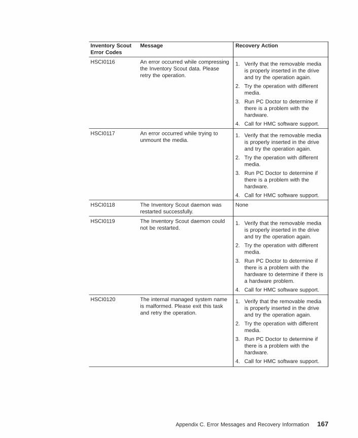
Inventory ScoutError Codes
Message Recovery Action
HSCI0116 An error occurred while compressingthe Inventory Scout data. Pleaseretry the operation.
1. Verify that the removable mediais properly inserted in the driveand try the operation again.
2. Try the operation with differentmedia.
3. Run PC Doctor to determine ifthere is a problem with thehardware.
4. Call for HMC software support.
HSCI0117 An error occurred while trying tounmount the media.
1. Verify that the removable mediais properly inserted in the driveand try the operation again.
2. Try the operation with differentmedia.
3. Run PC Doctor to determine ifthere is a problem with thehardware.
4. Call for HMC software support.
HSCI0118 The Inventory Scout daemon wasrestarted successfully.
None
HSCI0119 The Inventory Scout daemon couldnot be restarted.
1. Verify that the removable mediais properly inserted in the driveand try the operation again.
2. Try the operation with differentmedia.
3. Run PC Doctor to determine ifthere is a problem with thehardware to determine if there isa hardware problem.
4. Call for HMC software support.
HSCI0120 The internal managed system nameis malformed. Please exit this taskand retry the operation.
1. Verify that the removable mediais properly inserted in the driveand try the operation again.
2. Try the operation with differentmedia.
3. Run PC Doctor to determine ifthere is a problem with thehardware.
4. Call for HMC software support.
Appendix C. Error Messages and Recovery Information 167
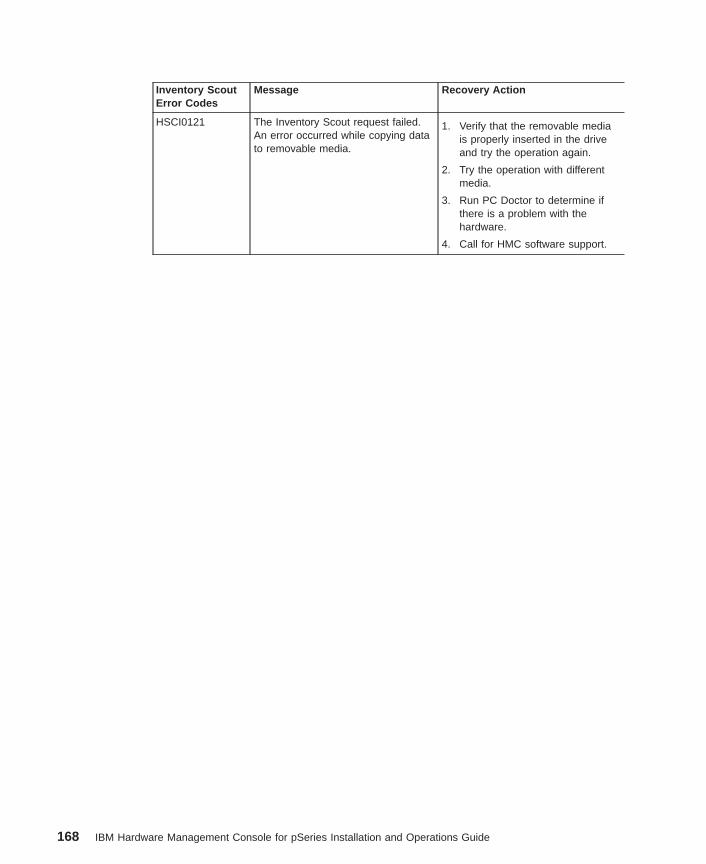
Inventory ScoutError Codes
Message Recovery Action
HSCI0121 The Inventory Scout request failed.An error occurred while copying datato removable media.
1. Verify that the removable mediais properly inserted in the driveand try the operation again.
2. Try the operation with differentmedia.
3. Run PC Doctor to determine ifthere is a problem with thehardware.
4. Call for HMC software support.
168 IBM Hardware Management Console for pSeries Installation and Operations Guide
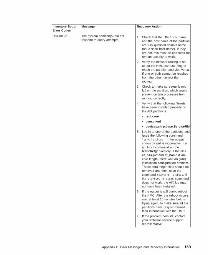
Inventory ScoutError Codes
Message Recovery Action
HSCI0122 The system partition(s) did notrespond to query attempts.
1. Check that the HMC host nameand the host name of the partitionare fully qualified domain name(not a short host name). If theyare not, this must be corrected forremote security to work.
2. Verify the network routing is setup so the HMC can use ping toreach the partition and vice versa.If one or both cannot be reachedfrom the other, correct therouting.
3. Check to make sure /var is notfull on the partition, which wouldprevent certain processes fromrunning correctly.
4. Verify that the following filesetshave been installed properly onthe AIX partitions:
v rsct.core
v csm.client
v devices.chrp.base.ServiceRM
5. Log in to one of the partitions andissue the following command:lssrc -s ctcas . If the outputshows ctcasd is inoperative, runan ls -l command on the/var/ct/cfg/ directory. If the filesct_has.pkf and ct_has.qkf arezero-length, there was an (AIX)installation configuration problem.These zero-length files should beremoved and then issue thecommand startsrc -s ctcas. Ifthe startsrc -s ctcas commanddoes not work, the AIX lpp maynot have been installed.
6. If the output is still blank, rebootthe HMC. After the reboot occurs,wait at least 10 minutes beforetrying again, to make sure all thepartitions have resynchronizedtheir information with the HMC.
7. If the problem persists, contactyour software service supportrepresentative.
Appendix C. Error Messages and Recovery Information 169
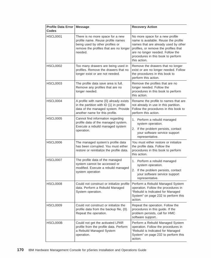
Profile Data ErrorCodes
Message Recovery Action
HSCL0001 There is no more space for a newprofile name. Reuse profile namesbeing used by other profiles orremove the profiles that are no longerneeded.
No more space for a new profilename is available. Reuse the profilenames that are already used by otherprofiles, or remove the profiles thatare no longer needed. Follow theprocedures in this book to performthis action.
HSCL0002 Too many drawers are being used inprofiles. Remove the drawers that nolonger exist or are not needed.
Remove the drawers that no longerexist or are no longer needed. Followthe procedures in this book toperform this action.
HSCL0003 The profile data save area is full.Remove any profiles that are nolonger needed.
Remove the profiles that are nolonger needed. Follow theprocedures in this book to performthis action.
HSCL0004 A profile with name {0} already existsin the partition with ID {1} in profiledata of the managed system. Provideanother name for this profile.
Rename the profile to names that arenot already in use in this partition.Follow the procedures in this book toperform this action.
HSCL0005 Cannot find information regardingprofile data of the managed system.Execute a rebuild managed systemoperation.
1. Perform a rebuild managedsystem operation.
2. If the problem persists, contactyour software service supportrepresentative.
HSCL0006 The managed system’s profile datahas been corrupted. You must eitherrestore or reinitialize the profile data.
You must either restore or initializethe profile data. Follow theprocedures in this book to performthis action.
HSCL0007 The profile data of the managedsystem cannot be accessed ormodified. Execute a rebuild managedsystem operation
1. Perform a rebuild managedsystem operation.
2. If the problem persists, contactyour software service supportrepresentative.
HSCL0008 Could not construct or initialize profiledata. Perform a Rebuild ManagedSystem operation.
Perform a Rebuild Managed Systemoperation. Follow the procedures in“Rebuild is Indicated for ManagedSystem” on page 232 to perform thisaction.
HSCL0009 Could not construct or initialize theprofile data from the backup file, {0}.Repeat the operation.
Repeat the operation. Follow theprocedures in this guide. If theproblem persists, call for HMCsoftware support..
HSCL000B Could not get the activated LPARprofile from the profile data. Performa Rebuild Managed Systemoperation.
Perform a Rebuild Managed Systemoperation. Follow the procedures in“Rebuild is Indicated for ManagedSystem” on page 232 to perform thisaction.
170 IBM Hardware Management Console for pSeries Installation and Operations Guide
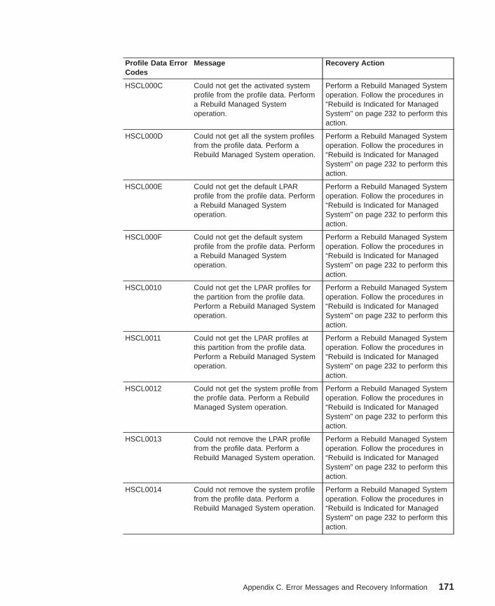
Profile Data ErrorCodes
Message Recovery Action
HSCL000C Could not get the activated systemprofile from the profile data. Performa Rebuild Managed Systemoperation.
Perform a Rebuild Managed Systemoperation. Follow the procedures in“Rebuild is Indicated for ManagedSystem” on page 232 to perform thisaction.
HSCL000D Could not get all the system profilesfrom the profile data. Perform aRebuild Managed System operation.
Perform a Rebuild Managed Systemoperation. Follow the procedures in“Rebuild is Indicated for ManagedSystem” on page 232 to perform thisaction.
HSCL000E Could not get the default LPARprofile from the profile data. Performa Rebuild Managed Systemoperation.
Perform a Rebuild Managed Systemoperation. Follow the procedures in“Rebuild is Indicated for ManagedSystem” on page 232 to perform thisaction.
HSCL000F Could not get the default systemprofile from the profile data. Performa Rebuild Managed Systemoperation.
Perform a Rebuild Managed Systemoperation. Follow the procedures in“Rebuild is Indicated for ManagedSystem” on page 232 to perform thisaction.
HSCL0010 Could not get the LPAR profiles forthe partition from the profile data.Perform a Rebuild Managed Systemoperation.
Perform a Rebuild Managed Systemoperation. Follow the procedures in“Rebuild is Indicated for ManagedSystem” on page 232 to perform thisaction.
HSCL0011 Could not get the LPAR profiles atthis partition from the profile data.Perform a Rebuild Managed Systemoperation.
Perform a Rebuild Managed Systemoperation. Follow the procedures in“Rebuild is Indicated for ManagedSystem” on page 232 to perform thisaction.
HSCL0012 Could not get the system profile fromthe profile data. Perform a RebuildManaged System operation.
Perform a Rebuild Managed Systemoperation. Follow the procedures in“Rebuild is Indicated for ManagedSystem” on page 232 to perform thisaction.
HSCL0013 Could not remove the LPAR profilefrom the profile data. Perform aRebuild Managed System operation.
Perform a Rebuild Managed Systemoperation. Follow the procedures in“Rebuild is Indicated for ManagedSystem” on page 232 to perform thisaction.
HSCL0014 Could not remove the system profilefrom the profile data. Perform aRebuild Managed System operation.
Perform a Rebuild Managed Systemoperation. Follow the procedures in“Rebuild is Indicated for ManagedSystem” on page 232 to perform thisaction.
Appendix C. Error Messages and Recovery Information 171
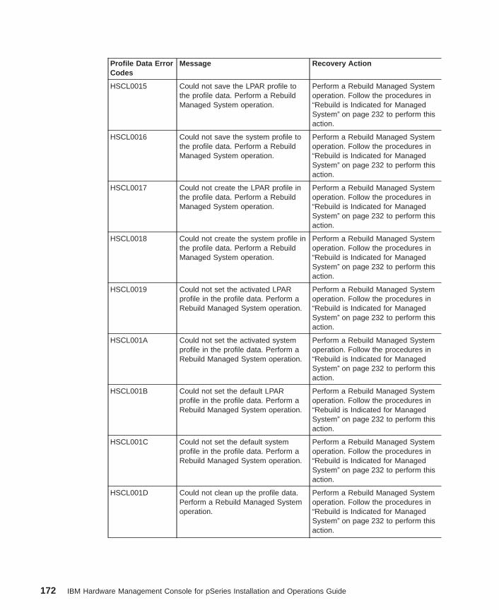
Profile Data ErrorCodes
Message Recovery Action
HSCL0015 Could not save the LPAR profile tothe profile data. Perform a RebuildManaged System operation.
Perform a Rebuild Managed Systemoperation. Follow the procedures in“Rebuild is Indicated for ManagedSystem” on page 232 to perform thisaction.
HSCL0016 Could not save the system profile tothe profile data. Perform a RebuildManaged System operation.
Perform a Rebuild Managed Systemoperation. Follow the procedures in“Rebuild is Indicated for ManagedSystem” on page 232 to perform thisaction.
HSCL0017 Could not create the LPAR profile inthe profile data. Perform a RebuildManaged System operation.
Perform a Rebuild Managed Systemoperation. Follow the procedures in“Rebuild is Indicated for ManagedSystem” on page 232 to perform thisaction.
HSCL0018 Could not create the system profile inthe profile data. Perform a RebuildManaged System operation.
Perform a Rebuild Managed Systemoperation. Follow the procedures in“Rebuild is Indicated for ManagedSystem” on page 232 to perform thisaction.
HSCL0019 Could not set the activated LPARprofile in the profile data. Perform aRebuild Managed System operation.
Perform a Rebuild Managed Systemoperation. Follow the procedures in“Rebuild is Indicated for ManagedSystem” on page 232 to perform thisaction.
HSCL001A Could not set the activated systemprofile in the profile data. Perform aRebuild Managed System operation.
Perform a Rebuild Managed Systemoperation. Follow the procedures in“Rebuild is Indicated for ManagedSystem” on page 232 to perform thisaction.
HSCL001B Could not set the default LPARprofile in the profile data. Perform aRebuild Managed System operation.
Perform a Rebuild Managed Systemoperation. Follow the procedures in“Rebuild is Indicated for ManagedSystem” on page 232 to perform thisaction.
HSCL001C Could not set the default systemprofile in the profile data. Perform aRebuild Managed System operation.
Perform a Rebuild Managed Systemoperation. Follow the procedures in“Rebuild is Indicated for ManagedSystem” on page 232 to perform thisaction.
HSCL001D Could not clean up the profile data.Perform a Rebuild Managed Systemoperation.
Perform a Rebuild Managed Systemoperation. Follow the procedures in“Rebuild is Indicated for ManagedSystem” on page 232 to perform thisaction.
172 IBM Hardware Management Console for pSeries Installation and Operations Guide
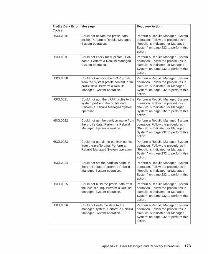
Profile Data ErrorCodes
Message Recovery Action
HSCL001E Could not update the profile datacache. Perform a Rebuild ManagedSystem operation.
Perform a Rebuild Managed Systemoperation. Follow the procedures in“Rebuild is Indicated for ManagedSystem” on page 232 to perform thisaction.
HSCL001F Could not check for duplicate LPARname. Perform a Rebuild ManagedSystem operation.
Perform a Rebuild Managed Systemoperation. Follow the procedures in“Rebuild is Indicated for ManagedSystem” on page 232 to perform thisaction.
HSCL0020 Could not remove the LPAR profilefrom the system profile content in theprofile data. Perform a RebuildManaged System operation.
Perform a Rebuild Managed Systemoperation. Follow the procedures in“Rebuild is Indicated for ManagedSystem” on page 232 to perform thisaction.
HSCL0021 Could not add the LPAR profile to thesystem profile in the profile data.Perform a Rebuild Managed Systemoperation.
Perform a Rebuild Managed Systemoperation. Follow the procedures in“Rebuild is Indicated for ManagedSystem” on page 232 to perform thisaction.
HSCL0022 Could not get the partition name fromthe profile data. Perform a RebuildManaged System operation.
Perform a Rebuild Managed Systemoperation. Follow the procedures in“Rebuild is Indicated for ManagedSystem” on page 232 to perform thisaction.
HSCL0023 Could not get all the partition namesfrom the profile data. Perform aRebuild Managed System operation.
Perform a Rebuild Managed Systemoperation. Follow the procedures in“Rebuild is Indicated for ManagedSystem” on page 232 to perform thisaction.
HSCL0024 Could not set the partition name inthe profile data. Perform a RebuildManaged System operation.
Perform a Rebuild Managed Systemoperation. Follow the procedures in“Rebuild is Indicated for ManagedSystem” on page 232 to perform thisaction.
HSCL0025 Could not build the profile data fromthe local file, {0}. Perform a RebuildManaged System operation.
Perform a Rebuild Managed Systemoperation. Follow the procedures in“Rebuild is Indicated for ManagedSystem” on page 232 to perform thisaction.
HSCL0026 Could not write the data to themanaged system. Perform a RebuildManaged System operation.
Perform a Rebuild Managed Systemoperation. Follow the procedures in“Rebuild is Indicated for ManagedSystem” on page 232 to perform thisaction.
Appendix C. Error Messages and Recovery Information 173
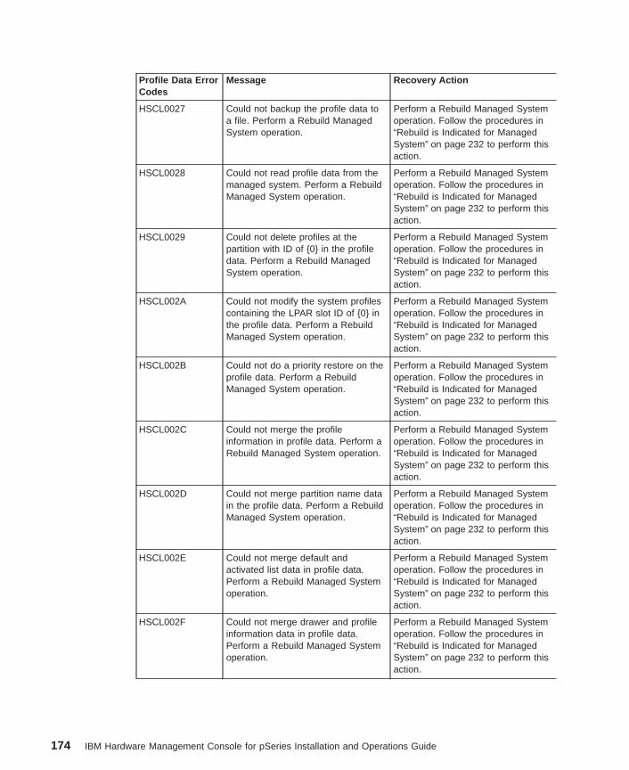
Profile Data ErrorCodes
Message Recovery Action
HSCL0027 Could not backup the profile data toa file. Perform a Rebuild ManagedSystem operation.
Perform a Rebuild Managed Systemoperation. Follow the procedures in“Rebuild is Indicated for ManagedSystem” on page 232 to perform thisaction.
HSCL0028 Could not read profile data from themanaged system. Perform a RebuildManaged System operation.
Perform a Rebuild Managed Systemoperation. Follow the procedures in“Rebuild is Indicated for ManagedSystem” on page 232 to perform thisaction.
HSCL0029 Could not delete profiles at thepartition with ID of {0} in the profiledata. Perform a Rebuild ManagedSystem operation.
Perform a Rebuild Managed Systemoperation. Follow the procedures in“Rebuild is Indicated for ManagedSystem” on page 232 to perform thisaction.
HSCL002A Could not modify the system profilescontaining the LPAR slot ID of {0} inthe profile data. Perform a RebuildManaged System operation.
Perform a Rebuild Managed Systemoperation. Follow the procedures in“Rebuild is Indicated for ManagedSystem” on page 232 to perform thisaction.
HSCL002B Could not do a priority restore on theprofile data. Perform a RebuildManaged System operation.
Perform a Rebuild Managed Systemoperation. Follow the procedures in“Rebuild is Indicated for ManagedSystem” on page 232 to perform thisaction.
HSCL002C Could not merge the profileinformation in profile data. Perform aRebuild Managed System operation.
Perform a Rebuild Managed Systemoperation. Follow the procedures in“Rebuild is Indicated for ManagedSystem” on page 232 to perform thisaction.
HSCL002D Could not merge partition name datain the profile data. Perform a RebuildManaged System operation.
Perform a Rebuild Managed Systemoperation. Follow the procedures in“Rebuild is Indicated for ManagedSystem” on page 232 to perform thisaction.
HSCL002E Could not merge default andactivated list data in profile data.Perform a Rebuild Managed Systemoperation.
Perform a Rebuild Managed Systemoperation. Follow the procedures in“Rebuild is Indicated for ManagedSystem” on page 232 to perform thisaction.
HSCL002F Could not merge drawer and profileinformation data in profile data.Perform a Rebuild Managed Systemoperation.
Perform a Rebuild Managed Systemoperation. Follow the procedures in“Rebuild is Indicated for ManagedSystem” on page 232 to perform thisaction.
174 IBM Hardware Management Console for pSeries Installation and Operations Guide
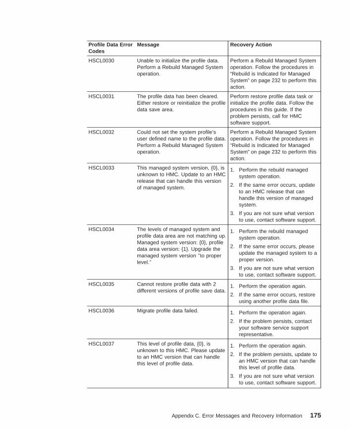
Profile Data ErrorCodes
Message Recovery Action
HSCL0030 Unable to initialize the profile data.Perform a Rebuild Managed Systemoperation.
Perform a Rebuild Managed Systemoperation. Follow the procedures in“Rebuild is Indicated for ManagedSystem” on page 232 to perform thisaction.
HSCL0031 The profile data has been cleared.Either restore or reinitialize the profiledata save area.
Perform restore profile data task orinitialize the profile data. Follow theprocedures in this guide. If theproblem persists, call for HMCsoftware support.
HSCL0032 Could not set the system profile’suser defined name to the profile data.Perform a Rebuild Managed Systemoperation.
Perform a Rebuild Managed Systemoperation. Follow the procedures in“Rebuild is Indicated for ManagedSystem” on page 232 to perform thisaction.
HSCL0033 This managed system version, {0}, isunknown to HMC. Update to an HMCrelease that can handle this versionof managed system.
1. Perform the rebuild managedsystem operation.
2. If the same error occurs, updateto an HMC release that canhandle this version of managedsystem.
3. If you are not sure what versionto use, contact software support.
HSCL0034 The levels of managed system andprofile data area are not matching up.Managed system version: {0}, profiledata area version: {1}. Upgrade themanaged system version ″to properlevel.″
1. Perform the rebuild managedsystem operation.
2. If the same error occurs, pleaseupdate the managed system to aproper version.
3. If you are not sure what versionto use, contact software support.
HSCL0035 Cannot restore profile data with 2different versions of profile save data.
1. Perform the operation again.
2. If the same error occurs, restoreusing another profile data file.
HSCL0036 Migrate profile data failed. 1. Perform the operation again.
2. If the problem persists, contactyour software service supportrepresentative.
HSCL0037 This level of profile data, {0}, isunknown to this HMC. Please updateto an HMC version that can handlethis level of profile data.
1. Perform the operation again.
2. If the problem persists, update toan HMC version that can handlethis level of profile data.
3. If you are not sure what versionto use, contact software support.
Appendix C. Error Messages and Recovery Information 175
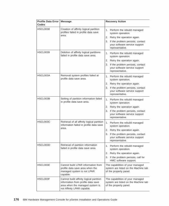
Profile Data ErrorCodes
Message Recovery Action
HSCL0038 Creation of affinity logical partitionprofiles failed in profile data savearea.
1. Perform the rebuild managedsystem operation.
2. Retry the operation again.
3. If the problem persists, contactyour software service supportrepresentative.
HSCL0039 Deletion of affinity logical partitionsfailed in profile data save area.
1. Perform the rebuild managedsystem operation.
2. Retry the operation again.
3. If the problem persists, contactyour software service supportrepresentative.
HSCL003A Removal system profiles failed atprofile data save area.
1. Perform the rebuild managedsystem operation.
2. Retry the operation again.
3. If the problem persists, contactyour software service supportrepresentative.
HSCL003B Setting of partition information failedin profile data save area.
1. Perform the rebuild managedsystem operation.
2. Retry the operation again.
3. If the problem persists, contactyour software service supportrepresentative.
HSCL003C Retrieval of all affinity logical partitioninformation failed in profile data savearea.
1. Perform the rebuild managedsystem operation.
2. Retry the operation again.
3. If the problem persists, contactyour software service supportrepresentative.
HSCL003D Retrieval of partition informationfailed in profile data save area.
1. Perform the rebuild managedsystem operation.
2. Retry the operation again.
3. If the problem persists, call forHMC software support.
HSCL003E Cannot build LPAR information fromprofile data save area when themanaged system is not LPARcapable.
The capabilities of your managedsystem are listed on the Machine tabof the property panel.
HSCL003F Cannot build affinity logical partitioninformation from profile data savearea when the managed system isnot Affinity LPAR capable.
The capabilities of your managedsystem are listed on the Machine tabof the property panel.
176 IBM Hardware Management Console for pSeries Installation and Operations Guide
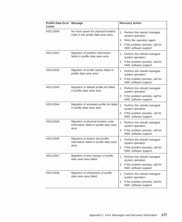
Profile Data ErrorCodes
Message Recovery Action
HSCL0040 No more space for physical locationcode in the profile data save area.
1. Perform the rebuild managedsystem operation
2. Retry the operation again.
3. If the problem persists, call forHMC software support.
HSCL0041 Migration of partition informationfailed in profile data save area
1. Perform the rebuild managedsystem operation.
2. If the problem persists, call forHMC software support.
HSCL0042 Migration of profile names failed inprofile data save area
1. Perform the rebuild managedsystem operation.
2. If the problem persists, call forHMC software support.
HSCL0043 Migration of default profile list failedin profile data save area
1. Perform the rebuild managedsystem operation.
2. If the problem persists, call forHMC software support.
HSCL0044 Migration of activated profile list failedin profile data save area
1. Perform the rebuild managedsystem operation.
2. If the problem persists, call forHMC software support.
HSCL0045 Migration of physical location codeinformation failed in profile data savearea
1. Perform the rebuild managedsystem operation.
2. If the problem persists, call forHMC software support.
HSCL0046 Migration of drawer and profileinformation failed in profile data savearea
1. Perform the rebuild managedsystem operation.
2. If the problem persists, call forHMC software support.
HSCL0047 Migration of time stamps of profiledata save area failed
1. Perform the rebuild managedsystem operation.
2. If the problem persists, call forHMC software support.
HSCL0048 Migration of checksums of profiledata save area failed
1. Perform the rebuild managedsystem operation.
2. If the problem persists, call forHMC software support.
Appendix C. Error Messages and Recovery Information 177
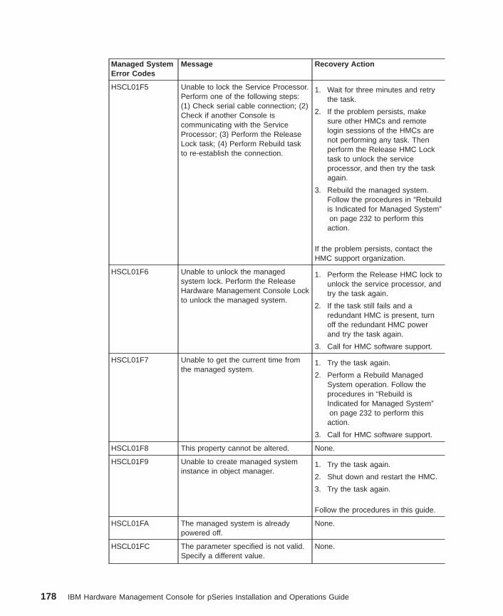
Managed SystemError Codes
Message Recovery Action
HSCL01F5 Unable to lock the Service Processor.Perform one of the following steps:(1) Check serial cable connection; (2)Check if another Console iscommunicating with the ServiceProcessor; (3) Perform the ReleaseLock task; (4) Perform Rebuild taskto re-establish the connection.
1. Wait for three minutes and retrythe task.
2. If the problem persists, makesure other HMCs and remotelogin sessions of the HMCs arenot performing any task. Thenperform the Release HMC Locktask to unlock the serviceprocessor, and then try the taskagain.
3. Rebuild the managed system.Follow the procedures in “Rebuildis Indicated for Managed System”on page 232 to perform this
action.
If the problem persists, contact theHMC support organization.
HSCL01F6 Unable to unlock the managedsystem lock. Perform the ReleaseHardware Management Console Lockto unlock the managed system.
1. Perform the Release HMC lock tounlock the service processor, andtry the task again.
2. If the task still fails and aredundant HMC is present, turnoff the redundant HMC powerand try the task again.
3. Call for HMC software support.
HSCL01F7 Unable to get the current time fromthe managed system.
1. Try the task again.
2. Perform a Rebuild ManagedSystem operation. Follow theprocedures in “Rebuild isIndicated for Managed System”on page 232 to perform this
action.
3. Call for HMC software support.
HSCL01F8 This property cannot be altered. None.
HSCL01F9 Unable to create managed systeminstance in object manager.
1. Try the task again.
2. Shut down and restart the HMC.
3. Try the task again.
Follow the procedures in this guide.
HSCL01FA The managed system is alreadypowered off.
None.
HSCL01FC The parameter specified is not valid.Specify a different value.
None.
178 IBM Hardware Management Console for pSeries Installation and Operations Guide
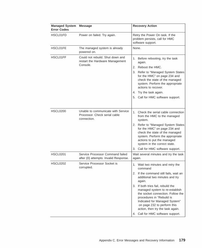
Managed SystemError Codes
Message Recovery Action
HSCL01FD Power on failed. Try again. Retry the Power On task. If theproblem persists, call for HMCsoftware support.
HSCL01FE The managed system is alreadypowered on.
None.
HSCL01FF Could not rebuild. Shut down andrestart the Hardware ManagementConsole.
1. Before rebooting, try the taskagain.
2. Reboot the HMC.
3. Refer to “Managed System Statesfor the HMC” on page 234 andcheck the state of the managedsystem. Perform the appropriateactions to recover.
4. Try the task again.
5. Call for HMC software support.
HSCL0200 Unable to communicate with ServiceProcessor. Check serial cableconnection.
1. Check the serial cable connectionfrom the HMC to the managedsystem.
2. Refer to “Managed System Statesfor the HMC” on page 234 andcheck the state of the managedsystem. Perform the appropriateactions to put the managedsystem in the correct state.
3. Call for HMC software support.
HSCL0201 Service Processor Command failedafter {0} attempts: Invalid Response.
Wait several minutes and try the taskagain.
HSCL0202 Service Processor Socket iscorrupted.
1. Wait two minutes and retry thecommand
2. If the command still fails, wait anadditional two minutes and tryagain.
3. If both tries fail, rebuild themanaged system to re-establishthe socket connection. Follow theprocedures in “Rebuild isIndicated for Managed System”on page 232 to perform this
action, then try the task again.
4. Call for HMC software support.
Appendix C. Error Messages and Recovery Information 179
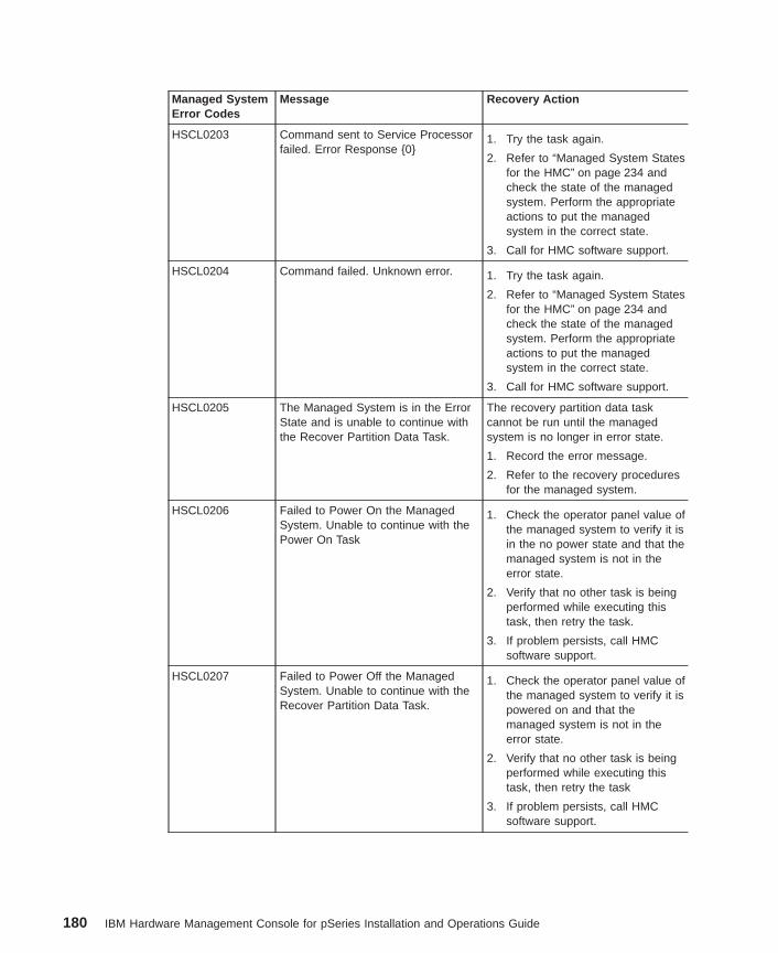
Managed SystemError Codes
Message Recovery Action
HSCL0203 Command sent to Service Processorfailed. Error Response {0}
1. Try the task again.
2. Refer to “Managed System Statesfor the HMC” on page 234 andcheck the state of the managedsystem. Perform the appropriateactions to put the managedsystem in the correct state.
3. Call for HMC software support.
HSCL0204 Command failed. Unknown error. 1. Try the task again.
2. Refer to “Managed System Statesfor the HMC” on page 234 andcheck the state of the managedsystem. Perform the appropriateactions to put the managedsystem in the correct state.
3. Call for HMC software support.
HSCL0205 The Managed System is in the ErrorState and is unable to continue withthe Recover Partition Data Task.
The recovery partition data taskcannot be run until the managedsystem is no longer in error state.
1. Record the error message.
2. Refer to the recovery proceduresfor the managed system.
HSCL0206 Failed to Power On the ManagedSystem. Unable to continue with thePower On Task
1. Check the operator panel value ofthe managed system to verify it isin the no power state and that themanaged system is not in theerror state.
2. Verify that no other task is beingperformed while executing thistask, then retry the task.
3. If problem persists, call HMCsoftware support.
HSCL0207 Failed to Power Off the ManagedSystem. Unable to continue with theRecover Partition Data Task.
1. Check the operator panel value ofthe managed system to verify it ispowered on and that themanaged system is not in theerror state.
2. Verify that no other task is beingperformed while executing thistask, then retry the task
3. If problem persists, call HMCsoftware support.
180 IBM Hardware Management Console for pSeries Installation and Operations Guide
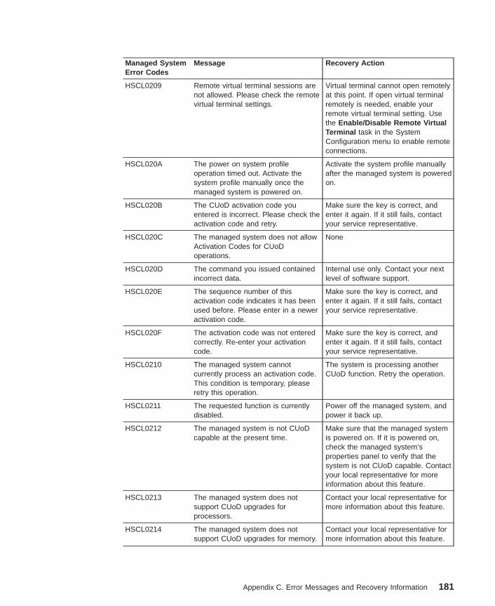
Managed SystemError Codes
Message Recovery Action
HSCL0209 Remote virtual terminal sessions arenot allowed. Please check the remotevirtual terminal settings.
Virtual terminal cannot open remotelyat this point. If open virtual terminalremotely is needed, enable yourremote virtual terminal setting. Usethe Enable/Disable Remote VirtualTerminal task in the SystemConfiguration menu to enable remoteconnections.
HSCL020A The power on system profileoperation timed out. Activate thesystem profile manually once themanaged system is powered on.
Activate the system profile manuallyafter the managed system is poweredon.
HSCL020B The CUoD activation code youentered is incorrect. Please check theactivation code and retry.
Make sure the key is correct, andenter it again. If it still fails, contactyour service representative.
HSCL020C The managed system does not allowActivation Codes for CUoDoperations.
None
HSCL020D The command you issued containedincorrect data.
Internal use only. Contact your nextlevel of software support.
HSCL020E The sequence number of thisactivation code indicates it has beenused before. Please enter in a neweractivation code.
Make sure the key is correct, andenter it again. If it still fails, contactyour service representative.
HSCL020F The activation code was not enteredcorrectly. Re-enter your activationcode.
Make sure the key is correct, andenter it again. If it still fails, contactyour service representative.
HSCL0210 The managed system cannotcurrently process an activation code.This condition is temporary, pleaseretry this operation.
The system is processing anotherCUoD function. Retry the operation.
HSCL0211 The requested function is currentlydisabled.
Power off the managed system, andpower it back up.
HSCL0212 The managed system is not CUoDcapable at the present time.
Make sure that the managed systemis powered on. If it is powered on,check the managed system’sproperties panel to verify that thesystem is not CUoD capable. Contactyour local representative for moreinformation about this feature.
HSCL0213 The managed system does notsupport CUoD upgrades forprocessors.
Contact your local representative formore information about this feature.
HSCL0214 The managed system does notsupport CUoD upgrades for memory.
Contact your local representative formore information about this feature.
Appendix C. Error Messages and Recovery Information 181
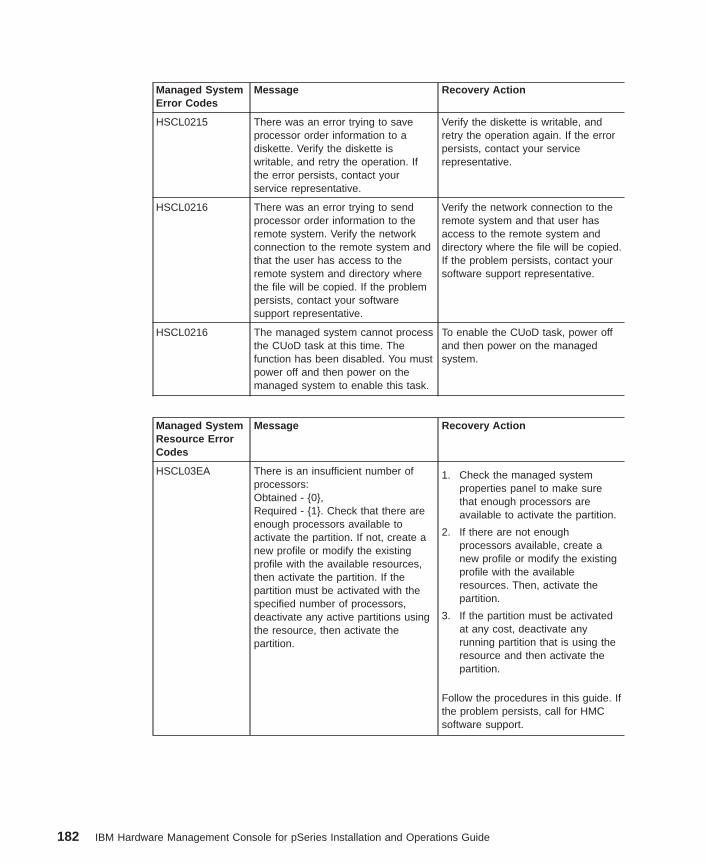
Managed SystemError Codes
Message Recovery Action
HSCL0215 There was an error trying to saveprocessor order information to adiskette. Verify the diskette iswritable, and retry the operation. Ifthe error persists, contact yourservice representative.
Verify the diskette is writable, andretry the operation again. If the errorpersists, contact your servicerepresentative.
HSCL0216 There was an error trying to sendprocessor order information to theremote system. Verify the networkconnection to the remote system andthat the user has access to theremote system and directory wherethe file will be copied. If the problempersists, contact your softwaresupport representative.
Verify the network connection to theremote system and that user hasaccess to the remote system anddirectory where the file will be copied.If the problem persists, contact yoursoftware support representative.
HSCL0216 The managed system cannot processthe CUoD task at this time. Thefunction has been disabled. You mustpower off and then power on themanaged system to enable this task.
To enable the CUoD task, power offand then power on the managedsystem.
Managed SystemResource ErrorCodes
Message Recovery Action
HSCL03EA There is an insufficient number ofprocessors:Obtained - {0},Required - {1}. Check that there areenough processors available toactivate the partition. If not, create anew profile or modify the existingprofile with the available resources,then activate the partition. If thepartition must be activated with thespecified number of processors,deactivate any active partitions usingthe resource, then activate thepartition.
1. Check the managed systemproperties panel to make surethat enough processors areavailable to activate the partition.
2. If there are not enoughprocessors available, create anew profile or modify the existingprofile with the availableresources. Then, activate thepartition.
3. If the partition must be activatedat any cost, deactivate anyrunning partition that is using theresource and then activate thepartition.
Follow the procedures in this guide. Ifthe problem persists, call for HMCsoftware support.
182 IBM Hardware Management Console for pSeries Installation and Operations Guide
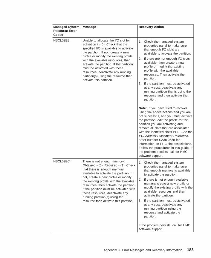
Managed SystemResource ErrorCodes
Message Recovery Action
HSCL03EB Unable to allocate the I/O slot foractivation in {0}. Check that thespecified I/O is available to activatethe partition. If not, create a newprofile or modify the existing profilewith the available resources, thenactivate the partition. If the partitionmust be activated with theseresources, deactivate any runningpartition(s) using the resource thenactivate this partition.
1. Check the managed systemproperties panel to make surethat enough I/O slots areavailable to activate the partition.
2. If there are not enough I/O slotsavailable, then create a newprofile or modify the existingprofile with the availableresources. Then activate thepartition.
3. If the partition must be activatedat any cost, deactivate anyrunning partition that is using theresource and then activate thepartition.
Note: If you have tried to recoverusing the above actions and you arenot successful, and you must activatethe partition, edit the profile for thepartition you are activating andremove all slots that are associatedwith the identified slot’s PHB. See thePCI Adapter Placement Reference,order number SA38-0538 forinformation on PHB slot associations.Follow the procedures in this guide. Ifthe problem persists, call for HMCsoftware support.
HSCL03EC There is not enough memory:Obtained - {0}, Required - {1}. Checkthat there is enough memoryavailable to activate the partition. Ifnot, create a new profile or modifythe existing profile with the availableresources, then activate the partition.If the partition must be activated withthese resources, deactivate anyrunning partition(s) using theresource then activate this partition.
1. Check the managed systemproperties panel to make surethat enough memory is availableto activate the partition.
2. If there is not enough availablememory, create a new profile ormodify the existing profile with theavailable resources and thenactivate the partition.
3. If the partition must be activatedat any cost, deactivate anyrunning partition using theresource and activate thepartition.
If the problem persists, call for HMCsoftware support.
Appendix C. Error Messages and Recovery Information 183
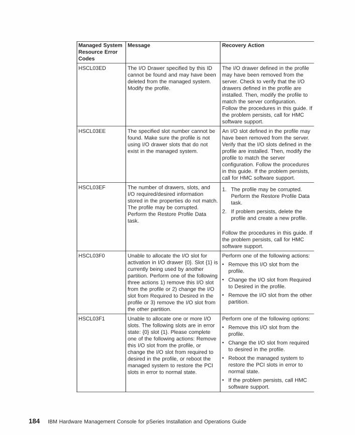
Managed SystemResource ErrorCodes
Message Recovery Action
HSCL03ED The I/O Drawer specified by this IDcannot be found and may have beendeleted from the managed system.Modify the profile.
The I/O drawer defined in the profilemay have been removed from theserver. Check to verify that the I/Odrawers defined in the profile areinstalled. Then, modify the profile tomatch the server configuration.Follow the procedures in this guide. Ifthe problem persists, call for HMCsoftware support.
HSCL03EE The specified slot number cannot befound. Make sure the profile is notusing I/O drawer slots that do notexist in the managed system.
An I/O slot defined in the profile mayhave been removed from the server.Verify that the I/O slots defined in theprofile are installed. Then, modify theprofile to match the serverconfiguration. Follow the proceduresin this guide. If the problem persists,call for HMC software support.
HSCL03EF The number of drawers, slots, andI/O required/desired informationstored in the properties do not match.The profile may be corrupted.Perform the Restore Profile Datatask.
1. The profile may be corrupted.Perform the Restore Profile Datatask.
2. If problem persists, delete theprofile and create a new profile.
Follow the procedures in this guide. Ifthe problem persists, call for HMCsoftware support.
HSCL03F0 Unable to allocate the I/O slot foractivation in I/O drawer {0}. Slot {1} iscurrently being used by anotherpartition. Perform one of the followingthree actions 1) remove this I/O slotfrom the profile or 2) change the I/Oslot from Required to Desired in theprofile or 3) remove the I/O slot fromthe other partition.
Perform one of the following actions:
v Remove this I/O slot from theprofile.
v Change the I/O slot from Requiredto Desired in the profile.
v Remove the I/O slot from the otherpartition.
HSCL03F1 Unable to allocate one or more I/Oslots. The following slots are in errorstate: {0} slot {1}. Please completeone of the following actions: Removethis I/O slot from the profile, orchange the I/O slot from required todesired in the profile, or reboot themanaged system to restore the PCIslots in error to normal state.
Perform one of the following options:
v Remove this I/O slot from theprofile.
v Change the I/O slot from requiredto desired in the profile.
v Reboot the managed system torestore the PCI slots in error tonormal state.
v If the problem persists, call HMCsoftware support.
184 IBM Hardware Management Console for pSeries Installation and Operations Guide
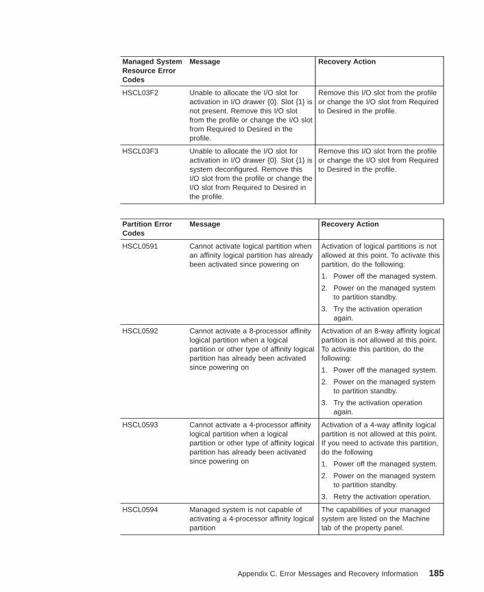
Managed SystemResource ErrorCodes
Message Recovery Action
HSCL03F2 Unable to allocate the I/O slot foractivation in I/O drawer {0}. Slot {1} isnot present. Remove this I/O slotfrom the profile or change the I/O slotfrom Required to Desired in theprofile.
Remove this I/O slot from the profileor change the I/O slot from Requiredto Desired in the profile.
HSCL03F3 Unable to allocate the I/O slot foractivation in I/O drawer {0}. Slot {1} issystem deconfigured. Remove thisI/O slot from the profile or change theI/O slot from Required to Desired inthe profile.
Remove this I/O slot from the profileor change the I/O slot from Requiredto Desired in the profile.
Partition ErrorCodes
Message Recovery Action
HSCL0591 Cannot activate logical partition whenan affinity logical partition has alreadybeen activated since powering on
Activation of logical partitions is notallowed at this point. To activate thispartition, do the following:
1. Power off the managed system.
2. Power on the managed systemto partition standby.
3. Try the activation operationagain.
HSCL0592 Cannot activate a 8-processor affinitylogical partition when a logicalpartition or other type of affinity logicalpartition has already been activatedsince powering on
Activation of an 8-way affinity logicalpartition is not allowed at this point.To activate this partition, do thefollowing:
1. Power off the managed system.
2. Power on the managed systemto partition standby.
3. Try the activation operationagain.
HSCL0593 Cannot activate a 4-processor affinitylogical partition when a logicalpartition or other type of affinity logicalpartition has already been activatedsince powering on
Activation of a 4-way affinity logicalpartition is not allowed at this point.If you need to activate this partition,do the following
1. Power off the managed system.
2. Power on the managed systemto partition standby.
3. Retry the activation operation.
HSCL0594 Managed system is not capable ofactivating a 4-processor affinity logicalpartition
The capabilities of your managedsystem are listed on the Machinetab of the property panel.
Appendix C. Error Messages and Recovery Information 185
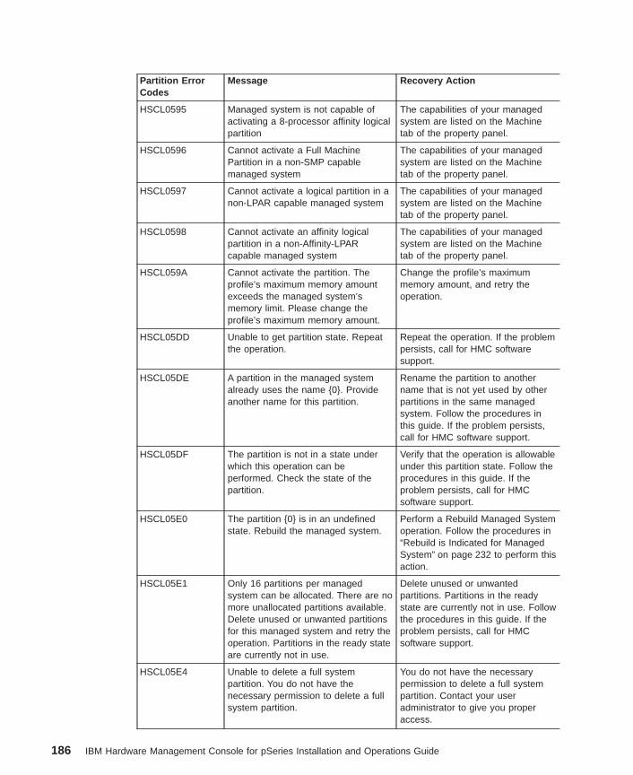
Partition ErrorCodes
Message Recovery Action
HSCL0595 Managed system is not capable ofactivating a 8-processor affinity logicalpartition
The capabilities of your managedsystem are listed on the Machinetab of the property panel.
HSCL0596 Cannot activate a Full MachinePartition in a non-SMP capablemanaged system
The capabilities of your managedsystem are listed on the Machinetab of the property panel.
HSCL0597 Cannot activate a logical partition in anon-LPAR capable managed system
The capabilities of your managedsystem are listed on the Machinetab of the property panel.
HSCL0598 Cannot activate an affinity logicalpartition in a non-Affinity-LPARcapable managed system
The capabilities of your managedsystem are listed on the Machinetab of the property panel.
HSCL059A Cannot activate the partition. Theprofile’s maximum memory amountexceeds the managed system’smemory limit. Please change theprofile’s maximum memory amount.
Change the profile’s maximummemory amount, and retry theoperation.
HSCL05DD Unable to get partition state. Repeatthe operation.
Repeat the operation. If the problempersists, call for HMC softwaresupport.
HSCL05DE A partition in the managed systemalready uses the name {0}. Provideanother name for this partition.
Rename the partition to anothername that is not yet used by otherpartitions in the same managedsystem. Follow the procedures inthis guide. If the problem persists,call for HMC software support.
HSCL05DF The partition is not in a state underwhich this operation can beperformed. Check the state of thepartition.
Verify that the operation is allowableunder this partition state. Follow theprocedures in this guide. If theproblem persists, call for HMCsoftware support.
HSCL05E0 The partition {0} is in an undefinedstate. Rebuild the managed system.
Perform a Rebuild Managed Systemoperation. Follow the procedures in“Rebuild is Indicated for ManagedSystem” on page 232 to perform thisaction.
HSCL05E1 Only 16 partitions per managedsystem can be allocated. There are nomore unallocated partitions available.Delete unused or unwanted partitionsfor this managed system and retry theoperation. Partitions in the ready stateare currently not in use.
Delete unused or unwantedpartitions. Partitions in the readystate are currently not in use. Followthe procedures in this guide. If theproblem persists, call for HMCsoftware support.
HSCL05E4 Unable to delete a full systempartition. You do not have thenecessary permission to delete a fullsystem partition.
You do not have the necessarypermission to delete a full systempartition. Contact your useradministrator to give you properaccess.
186 IBM Hardware Management Console for pSeries Installation and Operations Guide
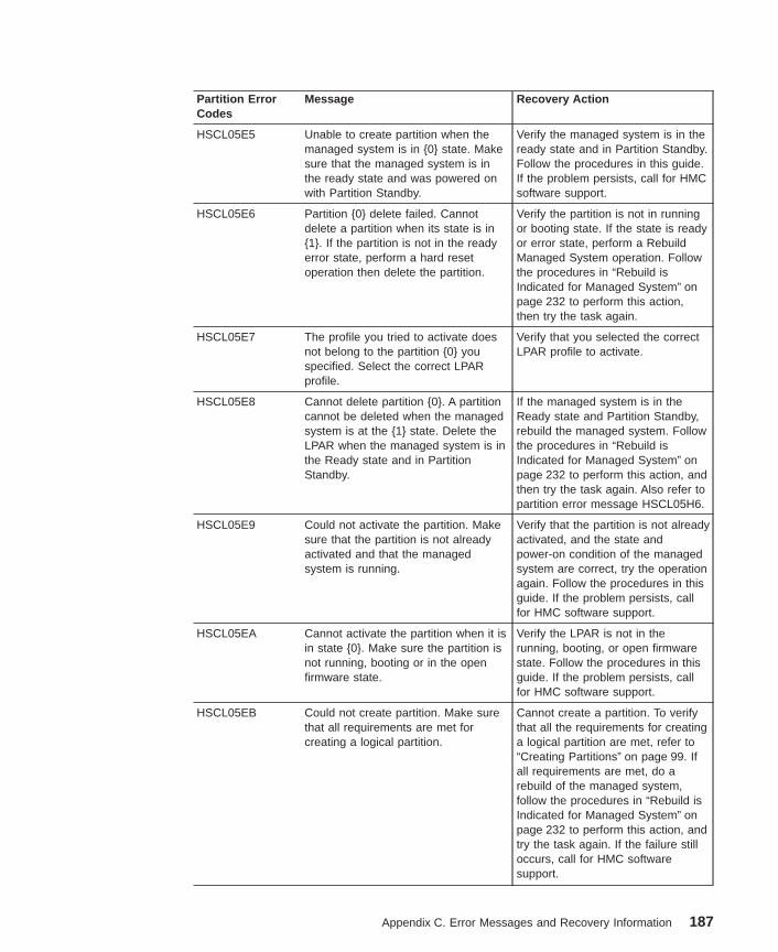
Partition ErrorCodes
Message Recovery Action
HSCL05E5 Unable to create partition when themanaged system is in {0} state. Makesure that the managed system is inthe ready state and was powered onwith Partition Standby.
Verify the managed system is in theready state and in Partition Standby.Follow the procedures in this guide.If the problem persists, call for HMCsoftware support.
HSCL05E6 Partition {0} delete failed. Cannotdelete a partition when its state is in{1}. If the partition is not in the readyerror state, perform a hard resetoperation then delete the partition.
Verify the partition is not in runningor booting state. If the state is readyor error state, perform a RebuildManaged System operation. Followthe procedures in “Rebuild isIndicated for Managed System” onpage 232 to perform this action,then try the task again.
HSCL05E7 The profile you tried to activate doesnot belong to the partition {0} youspecified. Select the correct LPARprofile.
Verify that you selected the correctLPAR profile to activate.
HSCL05E8 Cannot delete partition {0}. A partitioncannot be deleted when the managedsystem is at the {1} state. Delete theLPAR when the managed system is inthe Ready state and in PartitionStandby.
If the managed system is in theReady state and Partition Standby,rebuild the managed system. Followthe procedures in “Rebuild isIndicated for Managed System” onpage 232 to perform this action, andthen try the task again. Also refer topartition error message HSCL05H6.
HSCL05E9 Could not activate the partition. Makesure that the partition is not alreadyactivated and that the managedsystem is running.
Verify that the partition is not alreadyactivated, and the state andpower-on condition of the managedsystem are correct, try the operationagain. Follow the procedures in thisguide. If the problem persists, callfor HMC software support.
HSCL05EA Cannot activate the partition when it isin state {0}. Make sure the partition isnot running, booting or in the openfirmware state.
Verify the LPAR is not in therunning, booting, or open firmwarestate. Follow the procedures in thisguide. If the problem persists, callfor HMC software support.
HSCL05EB Could not create partition. Make surethat all requirements are met forcreating a logical partition.
Cannot create a partition. To verifythat all the requirements for creatinga logical partition are met, refer to“Creating Partitions” on page 99. Ifall requirements are met, do arebuild of the managed system,follow the procedures in “Rebuild isIndicated for Managed System” onpage 232 to perform this action, andtry the task again. If the failure stilloccurs, call for HMC softwaresupport.
Appendix C. Error Messages and Recovery Information 187
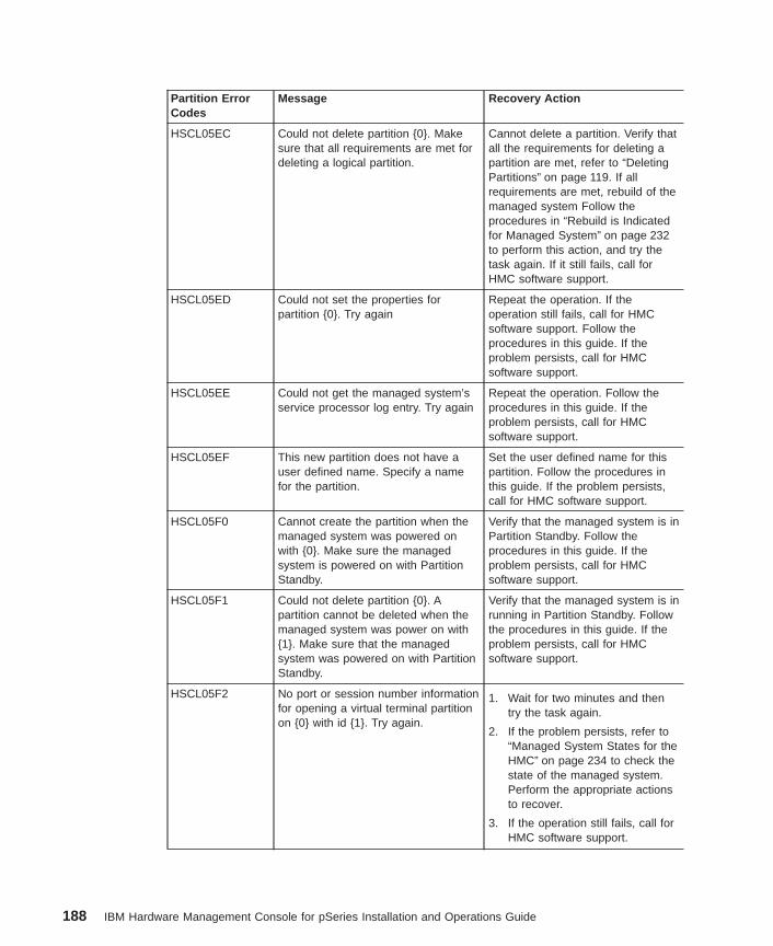
Partition ErrorCodes
Message Recovery Action
HSCL05EC Could not delete partition {0}. Makesure that all requirements are met fordeleting a logical partition.
Cannot delete a partition. Verify thatall the requirements for deleting apartition are met, refer to “DeletingPartitions” on page 119. If allrequirements are met, rebuild of themanaged system Follow theprocedures in “Rebuild is Indicatedfor Managed System” on page 232to perform this action, and try thetask again. If it still fails, call forHMC software support.
HSCL05ED Could not set the properties forpartition {0}. Try again
Repeat the operation. If theoperation still fails, call for HMCsoftware support. Follow theprocedures in this guide. If theproblem persists, call for HMCsoftware support.
HSCL05EE Could not get the managed system’sservice processor log entry. Try again
Repeat the operation. Follow theprocedures in this guide. If theproblem persists, call for HMCsoftware support.
HSCL05EF This new partition does not have auser defined name. Specify a namefor the partition.
Set the user defined name for thispartition. Follow the procedures inthis guide. If the problem persists,call for HMC software support.
HSCL05F0 Cannot create the partition when themanaged system was powered onwith {0}. Make sure the managedsystem is powered on with PartitionStandby.
Verify that the managed system is inPartition Standby. Follow theprocedures in this guide. If theproblem persists, call for HMCsoftware support.
HSCL05F1 Could not delete partition {0}. Apartition cannot be deleted when themanaged system was power on with{1}. Make sure that the managedsystem was powered on with PartitionStandby.
Verify that the managed system is inrunning in Partition Standby. Followthe procedures in this guide. If theproblem persists, call for HMCsoftware support.
HSCL05F2 No port or session number informationfor opening a virtual terminal partitionon {0} with id {1}. Try again.
1. Wait for two minutes and thentry the task again.
2. If the problem persists, refer to“Managed System States for theHMC” on page 234 to check thestate of the managed system.Perform the appropriate actionsto recover.
3. If the operation still fails, call forHMC software support.
188 IBM Hardware Management Console for pSeries Installation and Operations Guide
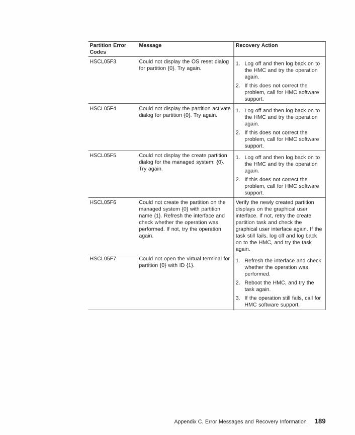
Partition ErrorCodes
Message Recovery Action
HSCL05F3 Could not display the OS reset dialogfor partition {0}. Try again.
1. Log off and then log back on tothe HMC and try the operationagain.
2. If this does not correct theproblem, call for HMC softwaresupport.
HSCL05F4 Could not display the partition activatedialog for partition {0}. Try again.
1. Log off and then log back on tothe HMC and try the operationagain.
2. If this does not correct theproblem, call for HMC softwaresupport.
HSCL05F5 Could not display the create partitiondialog for the managed system: {0}.Try again.
1. Log off and then log back on tothe HMC and try the operationagain.
2. If this does not correct theproblem, call for HMC softwaresupport.
HSCL05F6 Could not create the partition on themanaged system {0} with partitionname {1}. Refresh the interface andcheck whether the operation wasperformed. If not, try the operationagain.
Verify the newly created partitiondisplays on the graphical userinterface. If not, retry the createpartition task and check thegraphical user interface again. If thetask still fails, log off and log backon to the HMC, and try the taskagain.
HSCL05F7 Could not open the virtual terminal forpartition {0} with ID {1}.
1. Refresh the interface and checkwhether the operation wasperformed.
2. Reboot the HMC, and try thetask again.
3. If the operation still fails, call forHMC software support.
Appendix C. Error Messages and Recovery Information 189
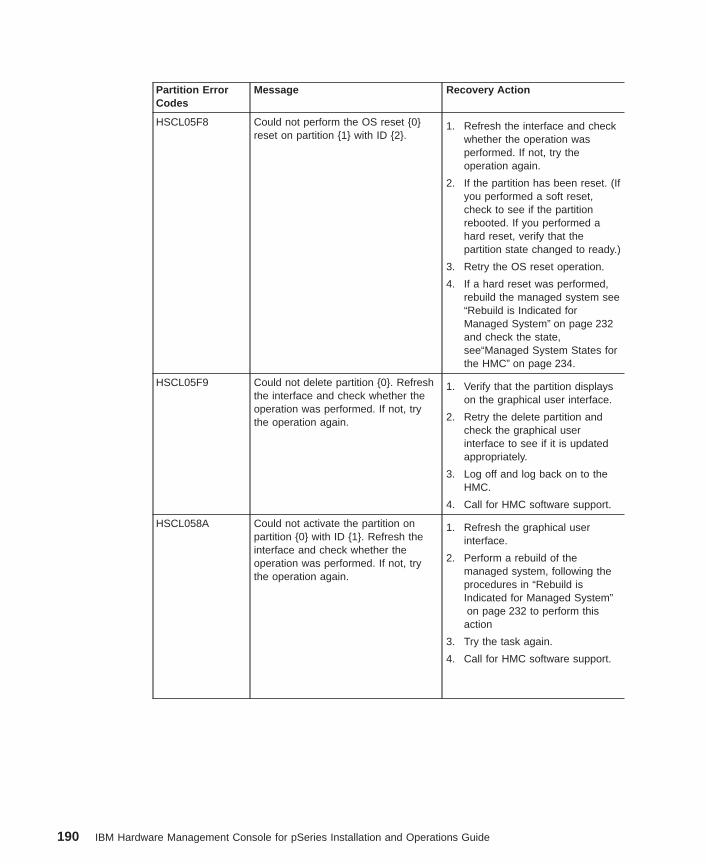
Partition ErrorCodes
Message Recovery Action
HSCL05F8 Could not perform the OS reset {0}reset on partition {1} with ID {2}.
1. Refresh the interface and checkwhether the operation wasperformed. If not, try theoperation again.
2. If the partition has been reset. (Ifyou performed a soft reset,check to see if the partitionrebooted. If you performed ahard reset, verify that thepartition state changed to ready.)
3. Retry the OS reset operation.
4. If a hard reset was performed,rebuild the managed system see“Rebuild is Indicated forManaged System” on page 232and check the state,see“Managed System States forthe HMC” on page 234.
HSCL05F9 Could not delete partition {0}. Refreshthe interface and check whether theoperation was performed. If not, trythe operation again.
1. Verify that the partition displayson the graphical user interface.
2. Retry the delete partition andcheck the graphical userinterface to see if it is updatedappropriately.
3. Log off and log back on to theHMC.
4. Call for HMC software support.
HSCL058A Could not activate the partition onpartition {0} with ID {1}. Refresh theinterface and check whether theoperation was performed. If not, trythe operation again.
1. Refresh the graphical userinterface.
2. Perform a rebuild of themanaged system, following theprocedures in “Rebuild isIndicated for Managed System”on page 232 to perform this
action
3. Try the task again.
4. Call for HMC software support.
190 IBM Hardware Management Console for pSeries Installation and Operations Guide
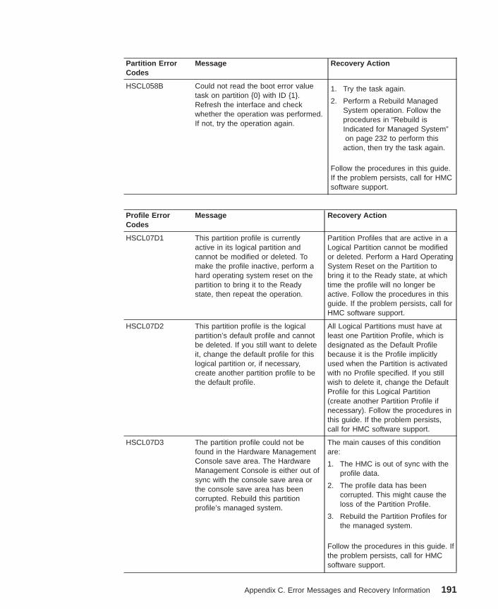
Partition ErrorCodes
Message Recovery Action
HSCL058B Could not read the boot error valuetask on partition {0} with ID {1}.Refresh the interface and checkwhether the operation was performed.If not, try the operation again.
1. Try the task again.
2. Perform a Rebuild ManagedSystem operation. Follow theprocedures in “Rebuild isIndicated for Managed System”on page 232 to perform this
action, then try the task again.
Follow the procedures in this guide.If the problem persists, call for HMCsoftware support.
Profile ErrorCodes
Message Recovery Action
HSCL07D1 This partition profile is currentlyactive in its logical partition andcannot be modified or deleted. Tomake the profile inactive, perform ahard operating system reset on thepartition to bring it to the Readystate, then repeat the operation.
Partition Profiles that are active in aLogical Partition cannot be modifiedor deleted. Perform a Hard OperatingSystem Reset on the Partition tobring it to the Ready state, at whichtime the profile will no longer beactive. Follow the procedures in thisguide. If the problem persists, call forHMC software support.
HSCL07D2 This partition profile is the logicalpartition’s default profile and cannotbe deleted. If you still want to deleteit, change the default profile for thislogical partition or, if necessary,create another partition profile to bethe default profile.
All Logical Partitions must have atleast one Partition Profile, which isdesignated as the Default Profilebecause it is the Profile implicitlyused when the Partition is activatedwith no Profile specified. If you stillwish to delete it, change the DefaultProfile for this Logical Partition(create another Partition Profile ifnecessary). Follow the procedures inthis guide. If the problem persists,call for HMC software support.
HSCL07D3 The partition profile could not befound in the Hardware ManagementConsole save area. The HardwareManagement Console is either out ofsync with the console save area orthe console save area has beencorrupted. Rebuild this partitionprofile’s managed system.
The main causes of this conditionare:
1. The HMC is out of sync with theprofile data.
2. The profile data has beencorrupted. This might cause theloss of the Partition Profile.
3. Rebuild the Partition Profiles forthe managed system.
Follow the procedures in this guide. Ifthe problem persists, call for HMCsoftware support.
Appendix C. Error Messages and Recovery Information 191
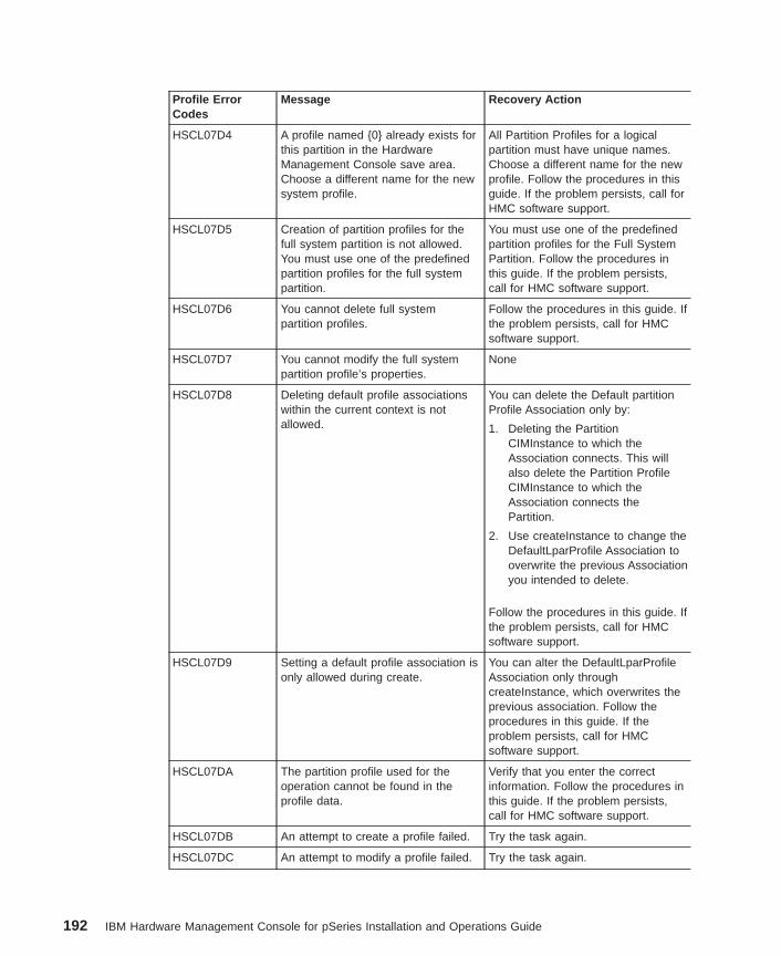
Profile ErrorCodes
Message Recovery Action
HSCL07D4 A profile named {0} already exists forthis partition in the HardwareManagement Console save area.Choose a different name for the newsystem profile.
All Partition Profiles for a logicalpartition must have unique names.Choose a different name for the newprofile. Follow the procedures in thisguide. If the problem persists, call forHMC software support.
HSCL07D5 Creation of partition profiles for thefull system partition is not allowed.You must use one of the predefinedpartition profiles for the full systempartition.
You must use one of the predefinedpartition profiles for the Full SystemPartition. Follow the procedures inthis guide. If the problem persists,call for HMC software support.
HSCL07D6 You cannot delete full systempartition profiles.
Follow the procedures in this guide. Ifthe problem persists, call for HMCsoftware support.
HSCL07D7 You cannot modify the full systempartition profile’s properties.
None
HSCL07D8 Deleting default profile associationswithin the current context is notallowed.
You can delete the Default partitionProfile Association only by:
1. Deleting the PartitionCIMInstance to which theAssociation connects. This willalso delete the Partition ProfileCIMInstance to which theAssociation connects thePartition.
2. Use createInstance to change theDefaultLparProfile Association tooverwrite the previous Associationyou intended to delete.
Follow the procedures in this guide. Ifthe problem persists, call for HMCsoftware support.
HSCL07D9 Setting a default profile association isonly allowed during create.
You can alter the DefaultLparProfileAssociation only throughcreateInstance, which overwrites theprevious association. Follow theprocedures in this guide. If theproblem persists, call for HMCsoftware support.
HSCL07DA The partition profile used for theoperation cannot be found in theprofile data.
Verify that you enter the correctinformation. Follow the procedures inthis guide. If the problem persists,call for HMC software support.
HSCL07DB An attempt to create a profile failed. Try the task again.
HSCL07DC An attempt to modify a profile failed. Try the task again.
192 IBM Hardware Management Console for pSeries Installation and Operations Guide
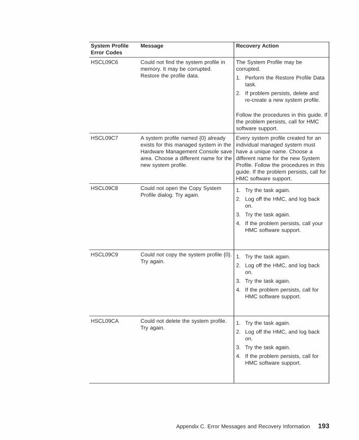
System ProfileError Codes
Message Recovery Action
HSCL09C6 Could not find the system profile inmemory. It may be corrupted.Restore the profile data.
The System Profile may becorrupted.
1. Perform the Restore Profile Datatask.
2. If problem persists, delete andre-create a new system profile.
Follow the procedures in this guide. Ifthe problem persists, call for HMCsoftware support.
HSCL09C7 A system profile named {0} alreadyexists for this managed system in theHardware Management Console savearea. Choose a different name for thenew system profile.
Every system profile created for anindividual managed system musthave a unique name. Choose adifferent name for the new SystemProfile. Follow the procedures in thisguide. If the problem persists, call forHMC software support.
HSCL09C8 Could not open the Copy SystemProfile dialog. Try again.
1. Try the task again.
2. Log off the HMC, and log backon.
3. Try the task again.
4. If the problem persists, call yourHMC software support.
HSCL09C9 Could not copy the system profile {0}.Try again.
1. Try the task again.
2. Log off the HMC, and log backon.
3. Try the task again.
4. If the problem persists, call forHMC software support.
HSCL09CA Could not delete the system profile.Try again.
1. Try the task again.
2. Log off the HMC, and log backon.
3. Try the task again.
4. If the problem persists, call forHMC software support.
Appendix C. Error Messages and Recovery Information 193
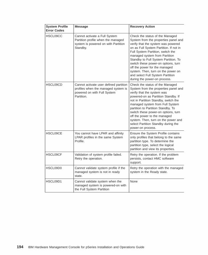
System ProfileError Codes
Message Recovery Action
HSCL09CC Cannot activate a Full SystemPartition profile when the managedsystem is powered on with PartitionStandby.
Check the status of the ManagedSystem from the properties panel andverify that the system was poweredon as Full System Partition. If not inFull System Partition, switch themanaged system from PartitionStandby to Full System Partition. Toswitch these power-on options, turnoff the power for the managedsystem. Then, turn on the power onand select Full System Partitionduring the power-on process.
HSCL09CD Cannot activate user defined partitionprofiles when the managed system ispowered on with Full SystemPartition.
Check the status of the ManagedSystem from the properties panel andverify that the system waspowered-on as Partition Standby. Ifnot in Partition Standby, switch themanaged system from Full Systempartition to Partition Standby. Toswitch these power-on options, turnoff the power to the managedsystem. Then, turn on the power andselect Partition Standby during thepower-on process.
HSCL09CE You cannot have LPAR and affinityLPAR profiles in the same SystemProfile.
Ensure the System Profile containsonly profiles that belong to the samepartition type. To determine thepartition type, select the logicalpartition and view its properties.
HSCL09CF Validation of system profile failed.Retry the operation.
Retry the operation. If the problempersists, contact HMC softwaresupport.
HSCL09D0 Cannot validate system profile if themanaged system is not in readystate.
Retry the operation with the managedsystem in the Ready state.
HSCL09D1 Cannot validate system when themanaged system is powered-on withthe Full System Partition
None
194 IBM Hardware Management Console for pSeries Installation and Operations Guide
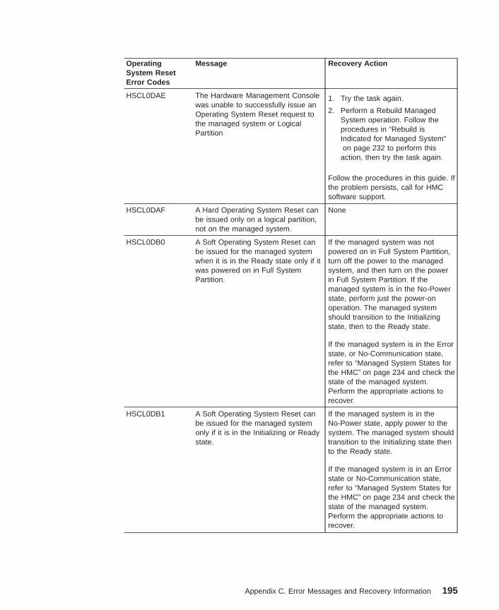
OperatingSystem ResetError Codes
Message Recovery Action
HSCL0DAE The Hardware Management Consolewas unable to successfully issue anOperating System Reset request tothe managed system or LogicalPartition
1. Try the task again.
2. Perform a Rebuild ManagedSystem operation. Follow theprocedures in “Rebuild isIndicated for Managed System”on page 232 to perform this
action, then try the task again.
Follow the procedures in this guide. Ifthe problem persists, call for HMCsoftware support.
HSCL0DAF A Hard Operating System Reset canbe issued only on a logical partition,not on the managed system.
None
HSCL0DB0 A Soft Operating System Reset canbe issued for the managed systemwhen it is in the Ready state only if itwas powered on in Full SystemPartition.
If the managed system was notpowered on in Full System Partition,turn off the power to the managedsystem, and then turn on the powerin Full System Partition. If themanaged system is in the No-Powerstate, perform just the power-onoperation. The managed systemshould transition to the Initializingstate, then to the Ready state.
If the managed system is in the Errorstate, or No-Communication state,refer to “Managed System States forthe HMC” on page 234 and check thestate of the managed system.Perform the appropriate actions torecover.
HSCL0DB1 A Soft Operating System Reset canbe issued for the managed systemonly if it is in the Initializing or Readystate.
If the managed system is in theNo-Power state, apply power to thesystem. The managed system shouldtransition to the Initializing state thento the Ready state.
If the managed system is in an Errorstate or No-Communication state,refer to “Managed System States forthe HMC” on page 234 and check thestate of the managed system.Perform the appropriate actions torecover.
Appendix C. Error Messages and Recovery Information 195
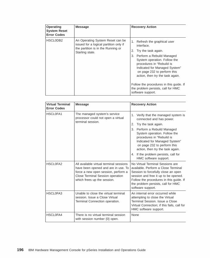
OperatingSystem ResetError Codes
Message Recovery Action
HSCL0DB2 An Operating System Reset can beissued for a logical partition only ifthe partition is in the Running orStarting state.
1. Refresh the graphical userinterface.
2. Try the task again.
3. Perform a Rebuild ManagedSystem operation. Follow theprocedures in “Rebuild isIndicated for Managed System”on page 232 to perform this
action, then try the task again.
Follow the procedures in this guide. Ifthe problem persists, call for HMCsoftware support.
Virtual TerminalError Codes
Message Recovery Action
HSCL0FA1 The managed system’s serviceprocessor could not open a virtualterminal session.
1. Verify that the managed system isconnected and has power.
2. Try the task again.
3. Perform a Rebuild ManagedSystem operation. Follow theprocedures in “Rebuild isIndicated for Managed System”on page 232 to perform this
action, then try the task again.
4. If the problem persists, call forHMC software support.
HSCL0FA2 All available virtual terminal sessionshave been opened and are in use. Toforce a new open session, perform aClose Terminal Session operationwhich frees up the session.
No Virtual Terminal Sessions areavailable. Perform a Close TerminalSession to forcefully close an opensession and free it up to be opened.Follow the procedures in this guide. Ifthe problem persists, call for HMCsoftware support.
HSCL0FA3 Unable to close the virtual terminalsession. Issue a Close VirtualTerminal Connection operation.
An internal error occurred whileattempting to close the VirtualTerminal Session. Issue a CloseVirtual Connection; if this fails, call forHMC software support.
HSCL0FA4 There is no virtual terminal sessionwith session number {0} open.
None
196 IBM Hardware Management Console for pSeries Installation and Operations Guide
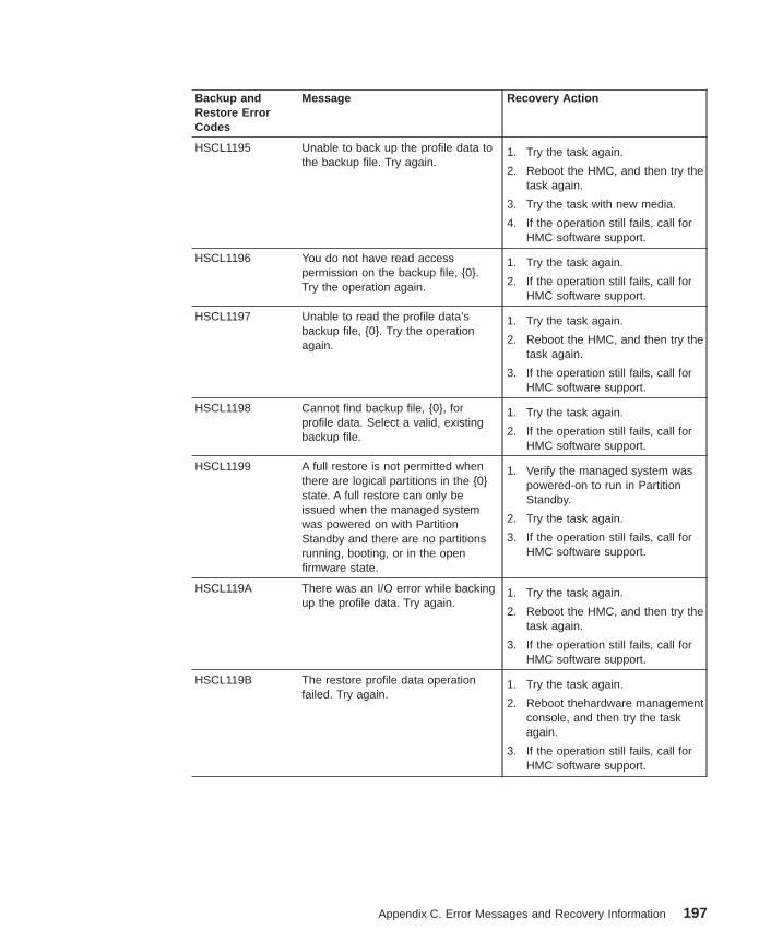
Backup andRestore ErrorCodes
Message Recovery Action
HSCL1195 Unable to back up the profile data tothe backup file. Try again.
1. Try the task again.
2. Reboot the HMC, and then try thetask again.
3. Try the task with new media.
4. If the operation still fails, call forHMC software support.
HSCL1196 You do not have read accesspermission on the backup file, {0}.Try the operation again.
1. Try the task again.
2. If the operation still fails, call forHMC software support.
HSCL1197 Unable to read the profile data’sbackup file, {0}. Try the operationagain.
1. Try the task again.
2. Reboot the HMC, and then try thetask again.
3. If the operation still fails, call forHMC software support.
HSCL1198 Cannot find backup file, {0}, forprofile data. Select a valid, existingbackup file.
1. Try the task again.
2. If the operation still fails, call forHMC software support.
HSCL1199 A full restore is not permitted whenthere are logical partitions in the {0}state. A full restore can only beissued when the managed systemwas powered on with PartitionStandby and there are no partitionsrunning, booting, or in the openfirmware state.
1. Verify the managed system waspowered-on to run in PartitionStandby.
2. Try the task again.
3. If the operation still fails, call forHMC software support.
HSCL119A There was an I/O error while backingup the profile data. Try again.
1. Try the task again.
2. Reboot the HMC, and then try thetask again.
3. If the operation still fails, call forHMC software support.
HSCL119B The restore profile data operationfailed. Try again.
1. Try the task again.
2. Reboot thehardware managementconsole, and then try the taskagain.
3. If the operation still fails, call forHMC software support.
Appendix C. Error Messages and Recovery Information 197
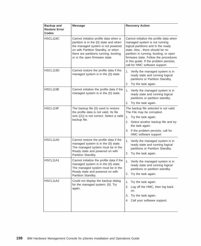
Backup andRestore ErrorCodes
Message Recovery Action
HSCL119C Cannot initialize profile data when apartition is in the {0} state and whenthe managed system is not poweredon with Partition Standby, or whenthere are partitions running, booting,or in the open firmware state.
Cannot initialize the profile data whenmanaged system is not runninglogical partitions and in the readystate. Also , there should be nopartition in running, booting, or openfirmware state. Follow the proceduresin this guide. If the problem persists,call for HMC software support.
HSCL119D Cannot restore the profile data if themanaged system is in the {0} state.
1. Verify the managed system is inready state and running logicalpartitions or Partition Standby.
2. Try the task again.
HSCL119E Cannot initialize the profile data if themanaged system is in the {0} state.
1. Verify the managed system is inready state and running logicalpartitions or partition standby.
2. Try the task again.
HSCL119F The backup file {0} used to restorethe profile data is not valid. Its filesize ({1}) is not correct. Select a validbackup file.
The backup file selected is not valid.The File may be corrupted.
1. Try the task again.
2. Select another backup file and trythe task again.
3. If the problem persists, call forHMC software support
HSCL11A0 Cannot restore the profile data if themanaged system is in the {0} state.The managed system must be in theReady state and powered on withPartition Standby.
1. Verify the managed system is inready state and running logicalpartitions or Partition Standby.
2. Try the task again.
HSCL11A1 Cannot initialize the profile data if themanaged system is in the {0} state.The managed system must be in theReady state and powered on withPartition Standby.
1. Verify the managed system is inready state and running logicalpartitions or partition standby.
2. Try the task again.
HSCL11A2 Could not display the backup dialogfor the managed system: {0}. Tryagain.
1. Try the task again.
2. Log off the HMC, then log backon.
3. Try the task again.
4. Call your software support.
198 IBM Hardware Management Console for pSeries Installation and Operations Guide
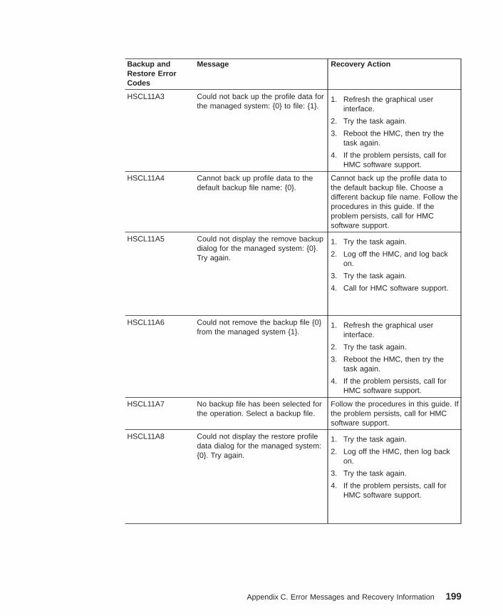
Backup andRestore ErrorCodes
Message Recovery Action
HSCL11A3 Could not back up the profile data forthe managed system: {0} to file: {1}.
1. Refresh the graphical userinterface.
2. Try the task again.
3. Reboot the HMC, then try thetask again.
4. If the problem persists, call forHMC software support.
HSCL11A4 Cannot back up profile data to thedefault backup file name: {0}.
Cannot back up the profile data tothe default backup file. Choose adifferent backup file name. Follow theprocedures in this guide. If theproblem persists, call for HMCsoftware support.
HSCL11A5 Could not display the remove backupdialog for the managed system: {0}.Try again.
1. Try the task again.
2. Log off the HMC, and log backon.
3. Try the task again.
4. Call for HMC software support.
HSCL11A6 Could not remove the backup file {0}from the managed system {1}.
1. Refresh the graphical userinterface.
2. Try the task again.
3. Reboot the HMC, then try thetask again.
4. If the problem persists, call forHMC software support.
HSCL11A7 No backup file has been selected forthe operation. Select a backup file.
Follow the procedures in this guide. Ifthe problem persists, call for HMCsoftware support.
HSCL11A8 Could not display the restore profiledata dialog for the managed system:{0}. Try again.
1. Try the task again.
2. Log off the HMC, then log backon.
3. Try the task again.
4. If the problem persists, call forHMC software support.
Appendix C. Error Messages and Recovery Information 199
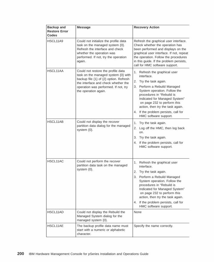
Backup andRestore ErrorCodes
Message Recovery Action
HSCL11A9 Could not initialize the profile datatask on the managed system {0}.Refresh the interface and checkwhether the operation wasperformed. If not, try the operationagain.
Refresh the graphical user interface.Check whether the operation hasbeen performed and displays on thegraphical user interface. If not, repeatthe operation. Follow the proceduresin this guide. If the problem persists,call for HMC software support.
HSCL11AA Could not restore the profile datatask on the managed system {0} withbackup file {1} of {2} option. Refreshthe interface and check whether theoperation was performed. If not, trythe operation again.
1. Refresh the graphical userinterface.
2. Try the task again.
3. Perform a Rebuild ManagedSystem operation. Follow theprocedures in “Rebuild isIndicated for Managed System”on page 232 to perform this
action, then try the task again.
4. If the problem persists, call forHMC software support.
HSCL11AB Could not display the recoverpartition data dialog for the managedsystem {0}.
1. Try the task again.
2. Log off the HMC, then log backon.
3. Try the task again.
4. If the problem persists, call forHMC software support.
HSCL11AC Could not perform the recoverpartition data task on the managedsystem {0}.
1. Refresh the graphical userinterface.
2. Try the task again.
3. Perform a Rebuild ManagedSystem operation. Follow theprocedures in “Rebuild isIndicated for Managed System”on page 232 to perform this
action, then try the task again.
4. If the problem persists, call forHMC software support.
HSCL11AD Could not display the Rebuild theManaged System dialog for themanaged system {0}.
None
HSCL11AE The backup profile data name muststart with a numeric or alphabeticcharacter.
Specify the name correctly.
200 IBM Hardware Management Console for pSeries Installation and Operations Guide
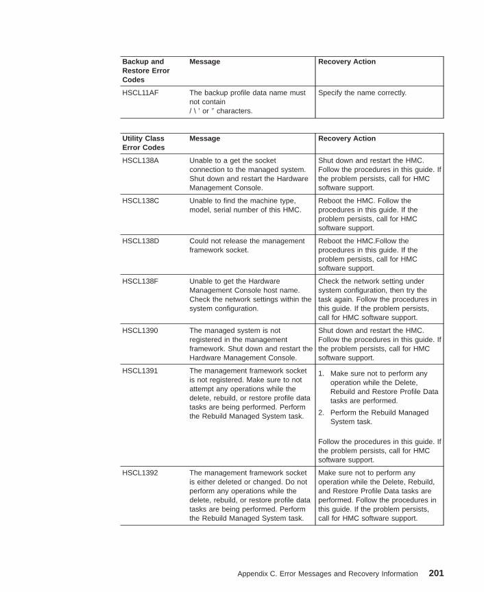
Backup andRestore ErrorCodes
Message Recovery Action
HSCL11AF The backup profile data name mustnot contain/ \ ’ or ″ characters.
Specify the name correctly.
Utility ClassError Codes
Message Recovery Action
HSCL138A Unable to a get the socketconnection to the managed system.Shut down and restart the HardwareManagement Console.
Shut down and restart the HMC.Follow the procedures in this guide. Ifthe problem persists, call for HMCsoftware support.
HSCL138C Unable to find the machine type,model, serial number of this HMC.
Reboot the HMC. Follow theprocedures in this guide. If theproblem persists, call for HMCsoftware support.
HSCL138D Could not release the managementframework socket.
Reboot the HMC.Follow theprocedures in this guide. If theproblem persists, call for HMCsoftware support.
HSCL138F Unable to get the HardwareManagement Console host name.Check the network settings within thesystem configuration.
Check the network setting undersystem configuration, then try thetask again. Follow the procedures inthis guide. If the problem persists,call for HMC software support.
HSCL1390 The managed system is notregistered in the managementframework. Shut down and restart theHardware Management Console.
Shut down and restart the HMC.Follow the procedures in this guide. Ifthe problem persists, call for HMCsoftware support.
HSCL1391 The management framework socketis not registered. Make sure to notattempt any operations while thedelete, rebuild, or restore profile datatasks are being performed. Performthe Rebuild Managed System task.
1. Make sure not to perform anyoperation while the Delete,Rebuild and Restore Profile Datatasks are performed.
2. Perform the Rebuild ManagedSystem task.
Follow the procedures in this guide. Ifthe problem persists, call for HMCsoftware support.
HSCL1392 The management framework socketis either deleted or changed. Do notperform any operations while thedelete, rebuild, or restore profile datatasks are being performed. Performthe Rebuild Managed System task.
Make sure not to perform anyoperation while the Delete, Rebuild,and Restore Profile Data tasks areperformed. Follow the procedures inthis guide. If the problem persists,call for HMC software support.
Appendix C. Error Messages and Recovery Information 201
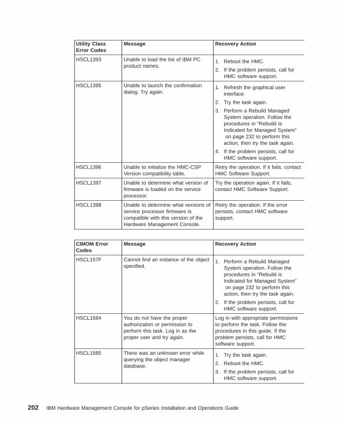
Utility ClassError Codes
Message Recovery Action
HSCL1393 Unable to load the list of IBM PCproduct names.
1. Reboot the HMC.
2. If the problem persists, call forHMC software support.
HSCL1395 Unable to launch the confirmationdialog. Try again.
1. Refresh the graphical userinterface.
2. Try the task again.
3. Perform a Rebuild ManagedSystem operation. Follow theprocedures in “Rebuild isIndicated for Managed System”on page 232 to perform this
action, then try the task again.
4. If the problem persists, call forHMC software support.
HSCL1396 Unable to initialize the HMC-CSPVersion compatibility table.
Retry the operation. If it fails, contactHMC Software Support.
HSCL1397 Unable to determine what version offirmware is loaded on the serviceprocessor.
Try the operation again. If it fails,contact HMC Software Support.
HSCL1398 Unable to determine what versions ofservice processor firmware iscompatible with this version of theHardware Management Console.
Retry the operation. If the errorpersists, contact HMC softwaresupport.
CIMOM ErrorCodes
Message Recovery Action
HSCL157F Cannot find an instance of the objectspecified.
1. Perform a Rebuild ManagedSystem operation. Follow theprocedures in “Rebuild isIndicated for Managed System”on page 232 to perform this
action, then try the task again.
2. If the problem persists, call forHMC software support.
HSCL1584 You do not have the properauthorization or permission toperform this task. Log in as theproper user and try again.
Log in with appropriate permissionsto perform the task. Follow theprocedures in this guide. If theproblem persists, call for HMCsoftware support.
HSCL1585 There was an unknown error whilequerying the object managerdatabase.
1. Try the task again.
2. Reboot the HMC.
3. If the problem persists, call forHMC software support.
202 IBM Hardware Management Console for pSeries Installation and Operations Guide
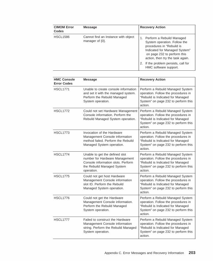
CIMOM ErrorCodes
Message Recovery Action
HSCL1586 Cannot find an Instance with objectmanager of {0}.
1. Perform a Rebuild ManagedSystem operation. Follow theprocedures in “Rebuild isIndicated for Managed System”on page 232 to perform this
action, then try the task again.
2. If the problem persists, call forHMC software support.
HMC ConsoleError Codes
Message Recovery Action
HSCL1771 Unable to create console informationand set it with the managed system.Perform the Rebuild ManagedSystem operation.
Perform a Rebuild Managed Systemoperation. Follow the procedures in“Rebuild is Indicated for ManagedSystem” on page 232 to perform thisaction.
HSCL1772 Could not set Hardware ManagementConsole information. Perform theRebuild Managed System operation.
Perform a Rebuild Managed Systemoperation. Follow the procedures in“Rebuild is Indicated for ManagedSystem” on page 232 to perform thisaction.
HSCL1773 Invocation of the HardwareManagement Console informationmethod failed. Perform the RebuildManaged System operation.
Perform a Rebuild Managed Systemoperation. Follow the procedures in“Rebuild is Indicated for ManagedSystem” on page 232 to perform thisaction.
HSCL1774 Unable to get the defined slotnumber for Hardware ManagementConsole information slots. Performthe Rebuild Managed Systemoperation.
Perform a Rebuild Managed Systemoperation. Follow the procedures in“Rebuild is Indicated for ManagedSystem” on page 232 to perform thisaction.
HSCL1775 Could not get host HardwareManagement Console informationslot ID. Perform the RebuildManaged System operation.
Perform a Rebuild Managed Systemoperation. Follow the procedures in“Rebuild is Indicated for ManagedSystem” on page 232 to perform thisaction.
HSCL1776 Could not get the HardwareManagement Console information.Perform the Rebuild ManagedSystem operation.
Perform a Rebuild Managed Systemoperation. Follow the procedures in“Rebuild is Indicated for ManagedSystem” on page 232 to perform thisaction.
HSCL1777 Failed to construct the HardwareManagement Console informationstring. Perform the Rebuild ManagedSystem operation.
Perform a Rebuild Managed Systemoperation. Follow the procedures in“Rebuild is Indicated for ManagedSystem” on page 232 to perform thisaction.
Appendix C. Error Messages and Recovery Information 203
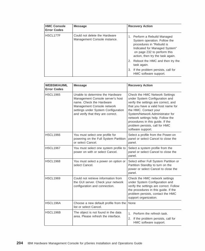
HMC ConsoleError Codes
Message Recovery Action
HSCL177F Could not delete the HardwareManagement Console instance.
1. Perform a Rebuild ManagedSystem operation. Follow theprocedures in “Rebuild isIndicated for Managed System”on page 232 to perform this
action, then try the task again.
2. Reboot the HMC and then try thetask again.
3. If the problem persists, call forHMC software support.
WEBSM/AUIMLError Codes
Message Recovery Action
HSCL1965 Unable to determine the HardwareManagement Console server’s hostname. Check the HardwareManagement Console networksettings under System Configurationand verify that they are correct.
Check the HMC Network Settingsunder System Configuration andverify the settings are correct, andthat you have a valid host name forthe HMC. Contact yourSystem/Network Administrator fornetwork settings help. Follow theprocedures in this guide. If theproblem persists, call for HMCsoftware support.
HSCL1966 You must select one profile forpowering on the Full System Partitionor select Cancel.
Select a profile from the Power-onpanel or select Cancel to close thepanel.
HSCL1967 You must select one system profile topower on with or select Cancel.
Select a system profile from thepanel or select Cancel to close thepanel.
HSCL1968 You must select a power on option orselect Cancel.
Select either Full System Partition orPartition Standby to turn on thepower or select Cancel to close thepanel.
HSCL1969 Could not retrieve information fromthe GUI server. Check your networkconfiguration and connection.
Check the HMC network settingsunder System Configuration andverify the settings are correct. Followthe procedures in this guide. If theproblem persists, contact the HMCsupport organization.
HSCL196A Choose a new default profile from thelist or select Cancel.
None
HSCL196B The object is not found in the dataarea. Please refresh the interface.
1. Perform the refresh task.
2. If the problem persists, call forHMC software support.
204 IBM Hardware Management Console for pSeries Installation and Operations Guide
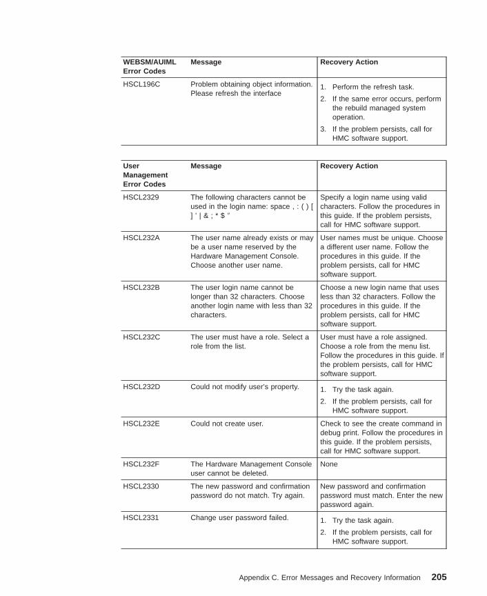
WEBSM/AUIMLError Codes
Message Recovery Action
HSCL196C Problem obtaining object information.Please refresh the interface
1. Perform the refresh task.
2. If the same error occurs, performthe rebuild managed systemoperation.
3. If the problem persists, call forHMC software support.
UserManagementError Codes
Message Recovery Action
HSCL2329 The following characters cannot beused in the login name: space , : ( ) [] ’ | & ; * $ ″
Specify a login name using validcharacters. Follow the procedures inthis guide. If the problem persists,call for HMC software support.
HSCL232A The user name already exists or maybe a user name reserved by theHardware Management Console.Choose another user name.
User names must be unique. Choosea different user name. Follow theprocedures in this guide. If theproblem persists, call for HMCsoftware support.
HSCL232B The user login name cannot belonger than 32 characters. Chooseanother login name with less than 32characters.
Choose a new login name that usesless than 32 characters. Follow theprocedures in this guide. If theproblem persists, call for HMCsoftware support.
HSCL232C The user must have a role. Select arole from the list.
User must have a role assigned.Choose a role from the menu list.Follow the procedures in this guide. Ifthe problem persists, call for HMCsoftware support.
HSCL232D Could not modify user’s property. 1. Try the task again.
2. If the problem persists, call forHMC software support.
HSCL232E Could not create user. Check to see the create command indebug print. Follow the procedures inthis guide. If the problem persists,call for HMC software support.
HSCL232F The Hardware Management Consoleuser cannot be deleted.
None
HSCL2330 The new password and confirmationpassword do not match. Try again.
New password and confirmationpassword must match. Enter the newpassword again.
HSCL2331 Change user password failed. 1. Try the task again.
2. If the problem persists, call forHMC software support.
Appendix C. Error Messages and Recovery Information 205
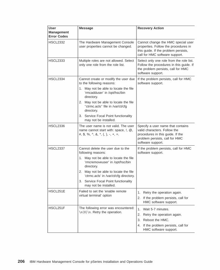
UserManagementError Codes
Message Recovery Action
HSCL2332 The Hardware Management Consoleuser properties cannot be changed.
Cannot change the HMC special userproperties. Follow the procedures inthis guide. If the problem persists,call for HMC software support.
HSCL2333 Multiple roles are not allowed. Selectonly one role from the role list.
Select only one role from the role list.Follow the procedures in this guide. Ifthe problem persists, call for HMCsoftware support.
HSCL2334 Cannot create or modify the user dueto the following reasons:
1. May not be able to locate the file’rmcadduser’ in /opt/hsc/bindirectory.
2. May not be able to locate the file’’ctrmc.acls’’ file in /var/ct/cfgdirectory.
3. Service Focal Point functionalitymay not be installed.
If the problem persists, call for HMCsoftware support.
HSCL2336 The user name is not valid. The username cannot start with: space, !, @,#, $, %, ^, &, *, (, ), -, +, =.
Specify a user name that containsvalid characters. Follow theprocedures in this guide. If theproblem persists, call for HMCsoftware support.
HSCL2337 Cannot delete the user due to thefollowing reasons:
1. May not be able to locate the file’rmcremoveuser’ in /opt/hsc/bindirectory.
2. May not be able to locate the file’ctrmc.acls’ in /var/ct/cfg directory.
3. Service Focal Point functionalitymay not be installed.
If the problem persists, call for HMCsoftware support.
HSCL251E Failed to set the ’enable remotevirtual terminal’ option
1. Retry the operation again.
2. If the problem persists, call forHMC software support.
HSCL251F The following error was encountered:\n{0}\n. Retry the operation.
1. Wait 5-7 minutes.
2. Retry the operation again.
3. Reboot the HMC.
4. If the problem persists, call forHMC software support.
206 IBM Hardware Management Console for pSeries Installation and Operations Guide
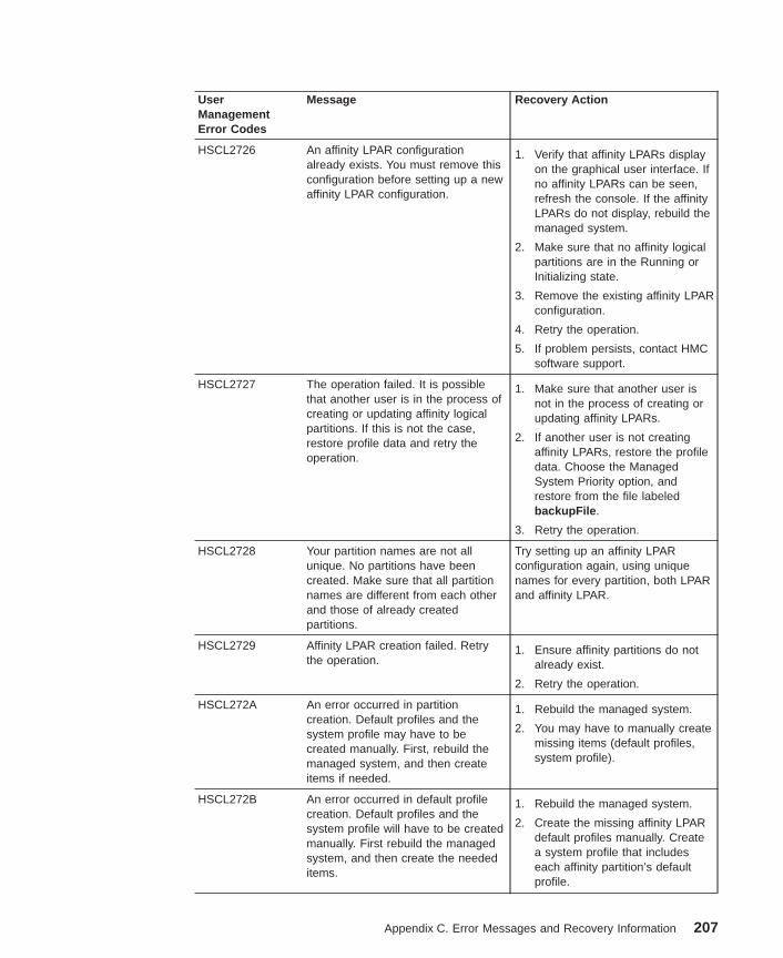
UserManagementError Codes
Message Recovery Action
HSCL2726 An affinity LPAR configurationalready exists. You must remove thisconfiguration before setting up a newaffinity LPAR configuration.
1. Verify that affinity LPARs displayon the graphical user interface. Ifno affinity LPARs can be seen,refresh the console. If the affinityLPARs do not display, rebuild themanaged system.
2. Make sure that no affinity logicalpartitions are in the Running orInitializing state.
3. Remove the existing affinity LPARconfiguration.
4. Retry the operation.
5. If problem persists, contact HMCsoftware support.
HSCL2727 The operation failed. It is possiblethat another user is in the process ofcreating or updating affinity logicalpartitions. If this is not the case,restore profile data and retry theoperation.
1. Make sure that another user isnot in the process of creating orupdating affinity LPARs.
2. If another user is not creatingaffinity LPARs, restore the profiledata. Choose the ManagedSystem Priority option, andrestore from the file labeledbackupFile .
3. Retry the operation.
HSCL2728 Your partition names are not allunique. No partitions have beencreated. Make sure that all partitionnames are different from each otherand those of already createdpartitions.
Try setting up an affinity LPARconfiguration again, using uniquenames for every partition, both LPARand affinity LPAR.
HSCL2729 Affinity LPAR creation failed. Retrythe operation.
1. Ensure affinity partitions do notalready exist.
2. Retry the operation.
HSCL272A An error occurred in partitioncreation. Default profiles and thesystem profile may have to becreated manually. First, rebuild themanaged system, and then createitems if needed.
1. Rebuild the managed system.
2. You may have to manually createmissing items (default profiles,system profile).
HSCL272B An error occurred in default profilecreation. Default profiles and thesystem profile will have to be createdmanually. First rebuild the managedsystem, and then create the neededitems.
1. Rebuild the managed system.
2. Create the missing affinity LPARdefault profiles manually. Createa system profile that includeseach affinity partition’s defaultprofile.
Appendix C. Error Messages and Recovery Information 207
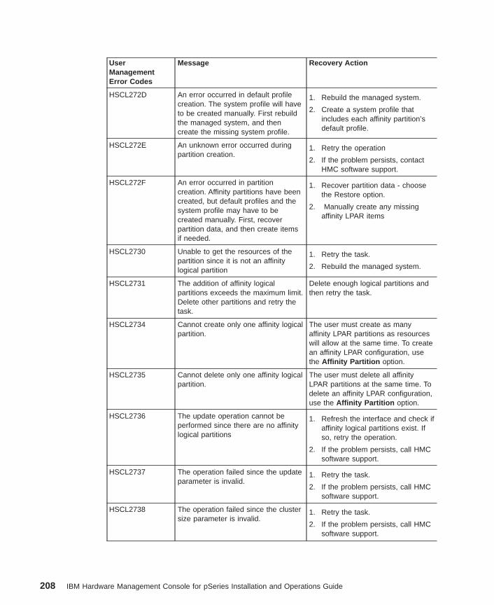
UserManagementError Codes
Message Recovery Action
HSCL272D An error occurred in default profilecreation. The system profile will haveto be created manually. First rebuildthe managed system, and thencreate the missing system profile.
1. Rebuild the managed system.
2. Create a system profile thatincludes each affinity partition’sdefault profile.
HSCL272E An unknown error occurred duringpartition creation.
1. Retry the operation
2. If the problem persists, contactHMC software support.
HSCL272F An error occurred in partitioncreation. Affinity partitions have beencreated, but default profiles and thesystem profile may have to becreated manually. First, recoverpartition data, and then create itemsif needed.
1. Recover partition data - choosethe Restore option.
2. Manually create any missingaffinity LPAR items
HSCL2730 Unable to get the resources of thepartition since it is not an affinitylogical partition
1. Retry the task.
2. Rebuild the managed system.
HSCL2731 The addition of affinity logicalpartitions exceeds the maximum limit.Delete other partitions and retry thetask.
Delete enough logical partitions andthen retry the task.
HSCL2734 Cannot create only one affinity logicalpartition.
The user must create as manyaffinity LPAR partitions as resourceswill allow at the same time. To createan affinity LPAR configuration, usethe Affinity Partition option.
HSCL2735 Cannot delete only one affinity logicalpartition.
The user must delete all affinityLPAR partitions at the same time. Todelete an affinity LPAR configuration,use the Affinity Partition option.
HSCL2736 The update operation cannot beperformed since there are no affinitylogical partitions
1. Refresh the interface and check ifaffinity logical partitions exist. Ifso, retry the operation.
2. If the problem persists, call HMCsoftware support.
HSCL2737 The operation failed since the updateparameter is invalid.
1. Retry the task.
2. If the problem persists, call HMCsoftware support.
HSCL2738 The operation failed since the clustersize parameter is invalid.
1. Retry the task.
2. If the problem persists, call HMCsoftware support.
208 IBM Hardware Management Console for pSeries Installation and Operations Guide
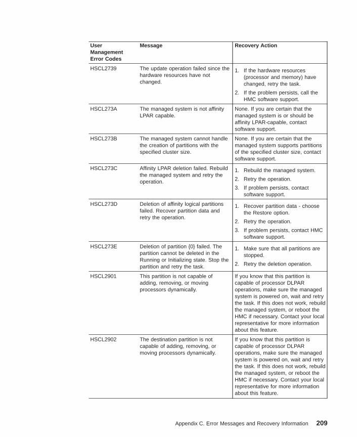
UserManagementError Codes
Message Recovery Action
HSCL2739 The update operation failed since thehardware resources have notchanged.
1. If the hardware resources(processor and memory) havechanged, retry the task.
2. If the problem persists, call theHMC software support.
HSCL273A The managed system is not affinityLPAR capable.
None. If you are certain that themanaged system is or should beaffinity LPAR-capable, contactsoftware support.
HSCL273B The managed system cannot handlethe creation of partitions with thespecified cluster size.
None. If you are certain that themanaged system supports partitionsof the specified cluster size, contactsoftware support.
HSCL273C Affinity LPAR deletion failed. Rebuildthe managed system and retry theoperation.
1. Rebuild the managed system.
2. Retry the operation.
3. If problem persists, contactsoftware support.
HSCL273D Deletion of affinity logical partitionsfailed. Recover partition data andretry the operation.
1. Recover partition data - choosethe Restore option.
2. Retry the operation.
3. If problem persists, contact HMCsoftware support.
HSCL273E Deletion of partition {0} failed. Thepartition cannot be deleted in theRunning or Initializing state. Stop thepartition and retry the task.
1. Make sure that all partitions arestopped.
2. Retry the deletion operation.
HSCL2901 This partition is not capable ofadding, removing, or movingprocessors dynamically.
If you know that this partition iscapable of processor DLPARoperations, make sure the managedsystem is powered on, wait and retrythe task. If this does not work, rebuildthe managed system, or reboot theHMC if necessary. Contact your localrepresentative for more informationabout this feature.
HSCL2902 The destination partition is notcapable of adding, removing, ormoving processors dynamically.
If you know that this partition iscapable of processor DLPARoperations, make sure the managedsystem is powered on, wait and retrythe task. If this does not work, rebuildthe managed system, or reboot theHMC if necessary. Contact your localrepresentative for more informationabout this feature.
Appendix C. Error Messages and Recovery Information 209
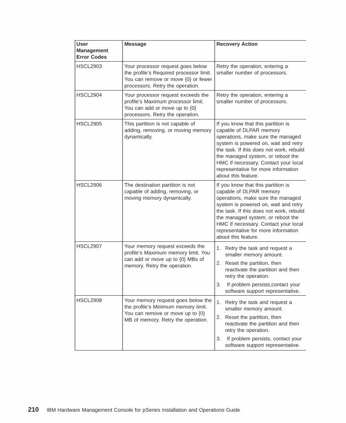
UserManagementError Codes
Message Recovery Action
HSCL2903 Your processor request goes belowthe profile’s Required processor limit.You can remove or move {0} or fewerprocessors. Retry the operation.
Retry the operation, entering asmaller number of processors.
HSCL2904 Your processor request exceeds theprofile’s Maximum processor limit.You can add or move up to {0}processors. Retry the operation.
Retry the operation, entering asmaller number of processors.
HSCL2905 This partition is not capable ofadding, removing, or moving memorydynamically.
If you know that this partition iscapable of DLPAR memoryoperations, make sure the managedsystem is powered on, wait and retrythe task. If this does not work, rebuildthe managed system, or reboot theHMC if necessary. Contact your localrepresentative for more informationabout this feature.
HSCL2906 The destination partition is notcapable of adding, removing, ormoving memory dynamically.
If you know that this partition iscapable of DLPAR memoryoperations, make sure the managedsystem is powered on, wait and retrythe task. If this does not work, rebuildthe managed system, or reboot theHMC if necessary. Contact your localrepresentative for more informationabout this feature.
HSCL2907 Your memory request exceeds theprofile’s Maximum memory limit. Youcan add or move up to {0} MBs ofmemory. Retry the operation.
1. Retry the task and request asmaller memory amount.
2. Reset the partition, thenreactivate the partition and thenretry the operation.
3. If problem persists,contact yoursoftware support representative.
HSCL2908 Your memory request goes below thethe profile’s Minimum memory limit.You can remove or move up to {0}MB of memory. Retry the operation.
1. Retry the task and request asmaller memory amount.
2. Reset the partition, thenreactivate the partition and thenretry the operation.
3. If problem persists, contact yoursoftware support representative.
210 IBM Hardware Management Console for pSeries Installation and Operations Guide
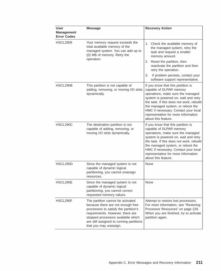
UserManagementError Codes
Message Recovery Action
HSCL2909 Your memory request exceeds thetotal available memory of themanaged system. You can add up to{0} MB of memory. Retry theoperation.
1. Check the available memory ofthe managed system, retry thetask and request a smallermemory amount.
2. Reset the partition, thenreactivate the partition and thenretry the operation.
3. If problem persists, contact yoursoftware support representative.
HSCL290B This partition is not capable ofadding, removing, or moving I/O slotsdynamically.
If you know that this partition iscapable of DLPAR memoryoperations, make sure the managedsystem is powered on, wait and retrythe task. If this does not work, rebuildthe managed system, or reboot theHMC if necessary. Contact your localrepresentative for more informationabout this feature.
HSCL290C The destination partition is notcapable of adding, removing, ormoving I/O slots dynamically.
If you know that this partition iscapable of DLPAR memoryoperations, make sure the managedsystem is powered on, wait and retrythe task. If this does not work, rebuildthe managed system, or reboot theHMC if necessary. Contact your localrepresentative for more informationabout this feature.
HSCL290D Since the managed system is notcapable of dynamic logicalpartitioning, you cannot unassignresources.
None
HSCL290E Since the managed system is notcapable of dynamic logicalpartitioning, you cannot correctrequested memory values.
None
HSCL290F The partition cannot be activatedbecause there are not enough freeprocessors to satisfy the partition’srequirements. However, there arestopped processors available whichare still assigned to running partitionsthat you may unassign.
Attempt to restore lost processors.For more information, see “RestoringProcessor Resources” on page 229.When you are finished, try to activatepartition again.
Appendix C. Error Messages and Recovery Information 211
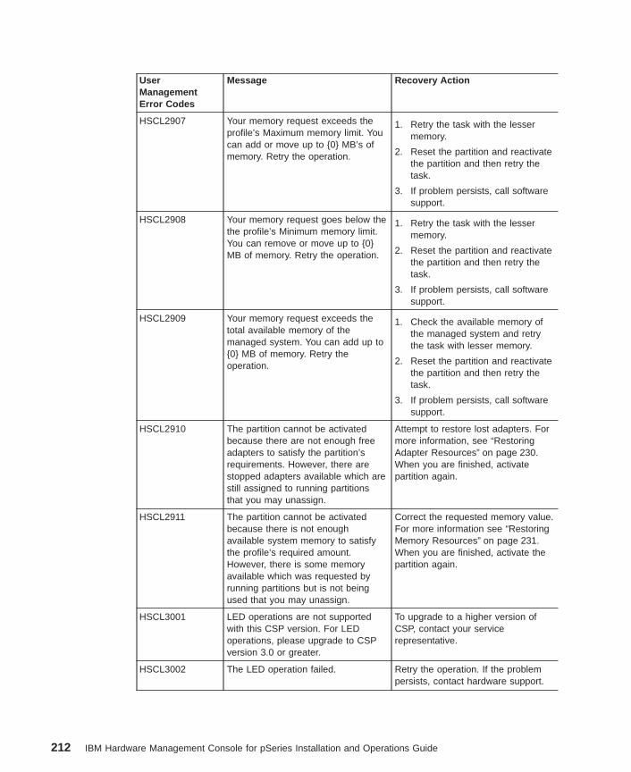
UserManagementError Codes
Message Recovery Action
HSCL2907 Your memory request exceeds theprofile’s Maximum memory limit. Youcan add or move up to {0} MB’s ofmemory. Retry the operation.
1. Retry the task with the lessermemory.
2. Reset the partition and reactivatethe partition and then retry thetask.
3. If problem persists, call softwaresupport.
HSCL2908 Your memory request goes below thethe profile’s Minimum memory limit.You can remove or move up to {0}MB of memory. Retry the operation.
1. Retry the task with the lessermemory.
2. Reset the partition and reactivatethe partition and then retry thetask.
3. If problem persists, call softwaresupport.
HSCL2909 Your memory request exceeds thetotal available memory of themanaged system. You can add up to{0} MB of memory. Retry theoperation.
1. Check the available memory ofthe managed system and retrythe task with lesser memory.
2. Reset the partition and reactivatethe partition and then retry thetask.
3. If problem persists, call softwaresupport.
HSCL2910 The partition cannot be activatedbecause there are not enough freeadapters to satisfy the partition’srequirements. However, there arestopped adapters available which arestill assigned to running partitionsthat you may unassign.
Attempt to restore lost adapters. Formore information, see “RestoringAdapter Resources” on page 230.When you are finished, activatepartition again.
HSCL2911 The partition cannot be activatedbecause there is not enoughavailable system memory to satisfythe profile’s required amount.However, there is some memoryavailable which was requested byrunning partitions but is not beingused that you may unassign.
Correct the requested memory value.For more information see “RestoringMemory Resources” on page 231.When you are finished, activate thepartition again.
HSCL3001 LED operations are not supportedwith this CSP version. For LEDoperations, please upgrade to CSPversion 3.0 or greater.
To upgrade to a higher version ofCSP, contact your servicerepresentative.
HSCL3002 The LED operation failed. Retry the operation. If the problempersists, contact hardware support.
212 IBM Hardware Management Console for pSeries Installation and Operations Guide
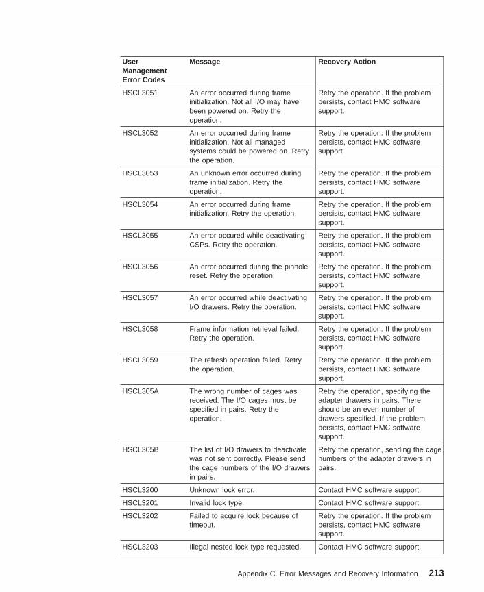
UserManagementError Codes
Message Recovery Action
HSCL3051 An error occurred during frameinitialization. Not all I/O may havebeen powered on. Retry theoperation.
Retry the operation. If the problempersists, contact HMC softwaresupport.
HSCL3052 An error occurred during frameinitialization. Not all managedsystems could be powered on. Retrythe operation.
Retry the operation. If the problempersists, contact HMC softwaresupport
HSCL3053 An unknown error occurred duringframe initialization. Retry theoperation.
Retry the operation. If the problempersists, contact HMC softwaresupport.
HSCL3054 An error occurred during frameinitialization. Retry the operation.
Retry the operation. If the problempersists, contact HMC softwaresupport.
HSCL3055 An error occured while deactivatingCSPs. Retry the operation.
Retry the operation. If the problempersists, contact HMC softwaresupport.
HSCL3056 An error occurred during the pinholereset. Retry the operation.
Retry the operation. If the problempersists, contact HMC softwaresupport.
HSCL3057 An error occurred while deactivatingI/O drawers. Retry the operation.
Retry the operation. If the problempersists, contact HMC softwaresupport.
HSCL3058 Frame information retrieval failed.Retry the operation.
Retry the operation. If the problempersists, contact HMC softwaresupport.
HSCL3059 The refresh operation failed. Retrythe operation.
Retry the operation. If the problempersists, contact HMC softwaresupport.
HSCL305A The wrong number of cages wasreceived. The I/O cages must bespecified in pairs. Retry theoperation.
Retry the operation, specifying theadapter drawers in pairs. Thereshould be an even number ofdrawers specified. If the problempersists, contact HMC softwaresupport.
HSCL305B The list of I/O drawers to deactivatewas not sent correctly. Please sendthe cage numbers of the I/O drawersin pairs.
Retry the operation, sending the cagenumbers of the adapter drawers inpairs.
HSCL3200 Unknown lock error. Contact HMC software support.
HSCL3201 Invalid lock type. Contact HMC software support.
HSCL3202 Failed to acquire lock because oftimeout.
Retry the operation. If the problempersists, contact HMC softwaresupport.
HSCL3203 Illegal nested lock type requested. Contact HMC software support.
Appendix C. Error Messages and Recovery Information 213
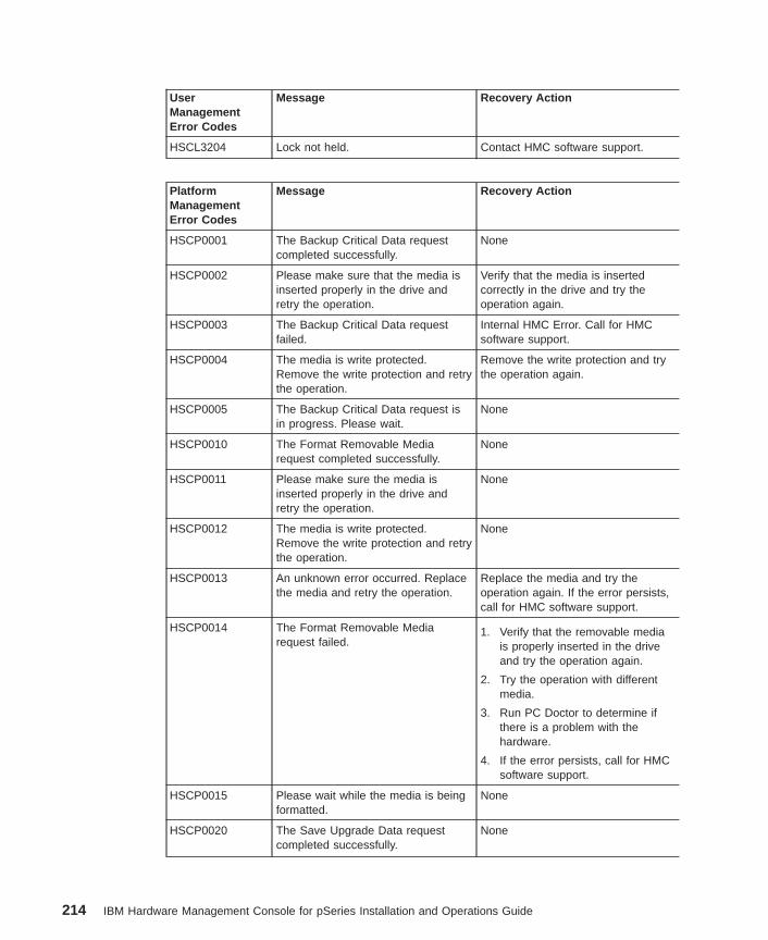
UserManagementError Codes
Message Recovery Action
HSCL3204 Lock not held. Contact HMC software support.
PlatformManagementError Codes
Message Recovery Action
HSCP0001 The Backup Critical Data requestcompleted successfully.
None
HSCP0002 Please make sure that the media isinserted properly in the drive andretry the operation.
Verify that the media is insertedcorrectly in the drive and try theoperation again.
HSCP0003 The Backup Critical Data requestfailed.
Internal HMC Error. Call for HMCsoftware support.
HSCP0004 The media is write protected.Remove the write protection and retrythe operation.
Remove the write protection and trythe operation again.
HSCP0005 The Backup Critical Data request isin progress. Please wait.
None
HSCP0010 The Format Removable Mediarequest completed successfully.
None
HSCP0011 Please make sure the media isinserted properly in the drive andretry the operation.
None
HSCP0012 The media is write protected.Remove the write protection and retrythe operation.
None
HSCP0013 An unknown error occurred. Replacethe media and retry the operation.
Replace the media and try theoperation again. If the error persists,call for HMC software support.
HSCP0014 The Format Removable Mediarequest failed.
1. Verify that the removable mediais properly inserted in the driveand try the operation again.
2. Try the operation with differentmedia.
3. Run PC Doctor to determine ifthere is a problem with thehardware.
4. If the error persists, call for HMCsoftware support.
HSCP0015 Please wait while the media is beingformatted.
None
HSCP0020 The Save Upgrade Data requestcompleted successfully.
None
214 IBM Hardware Management Console for pSeries Installation and Operations Guide
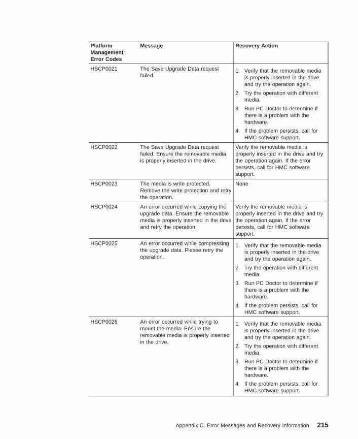
PlatformManagementError Codes
Message Recovery Action
HSCP0021 The Save Upgrade Data requestfailed.
1. Verify that the removable mediais properly inserted in the driveand try the operation again.
2. Try the operation with differentmedia.
3. Run PC Doctor to determine ifthere is a problem with thehardware.
4. If the problem persists, call forHMC software support.
HSCP0022 The Save Upgrade Data requestfailed. Ensure the removable mediais properly inserted in the drive.
Verify the removable media isproperly inserted in the drive and trythe operation again. If the errorpersists, call for HMC softwaresupport.
HSCP0023 The media is write protected.Remove the write protection and retrythe operation.
None
HSCP0024 An error occurred while copying theupgrade data. Ensure the removablemedia is properly inserted in the driveand retry the operation.
Verify the removable media isproperly inserted in the drive and trythe operation again. If the errorpersists, call for HMC softwaresupport.
HSCP0025 An error occurred while compressingthe upgrade data. Please retry theoperation.
1. Verify that the removable mediais properly inserted in the driveand try the operation again.
2. Try the operation with differentmedia.
3. Run PC Doctor to determine ifthere is a problem with thehardware.
4. If the problem persists, call forHMC software support.
HSCP0026 An error occurred while trying tomount the media. Ensure theremovable media is properly insertedin the drive.
1. Verify that the removable mediais properly inserted in the driveand try the operation again.
2. Try the operation with differentmedia.
3. Run PC Doctor to determine ifthere is a problem with thehardware.
4. If the problem persists, call forHMC software support.
Appendix C. Error Messages and Recovery Information 215
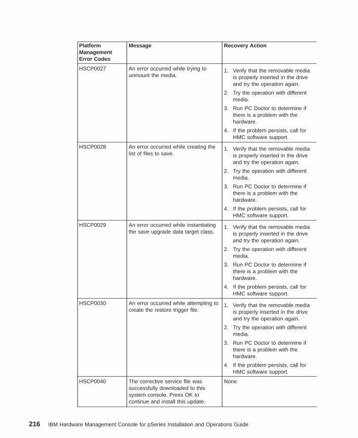
PlatformManagementError Codes
Message Recovery Action
HSCP0027 An error occurred while trying tounmount the media.
1. Verify that the removable mediais properly inserted in the driveand try the operation again.
2. Try the operation with differentmedia.
3. Run PC Doctor to determine ifthere is a problem with thehardware.
4. If the problem persists, call forHMC software support.
HSCP0028 An error occurred while creating thelist of files to save.
1. Verify that the removable mediais properly inserted in the driveand try the operation again.
2. Try the operation with differentmedia.
3. Run PC Doctor to determine ifthere is a problem with thehardware.
4. If the problem persists, call forHMC software support.
HSCP0029 An error occurred while instantiatingthe save upgrade data target class.
1. Verify that the removable mediais properly inserted in the driveand try the operation again.
2. Try the operation with differentmedia.
3. Run PC Doctor to determine ifthere is a problem with thehardware.
4. If the problem persists, call forHMC software support.
HSCP0030 An error occurred while attempting tocreate the restore trigger file.
1. Verify that the removable mediais properly inserted in the driveand try the operation again.
2. Try the operation with differentmedia.
3. Run PC Doctor to determine ifthere is a problem with thehardware.
4. If the problem persists, call forHMC software support.
HSCP0040 The corrective service file wassuccessfully downloaded to thissystem console. Press OK tocontinue and install this update.
None
216 IBM Hardware Management Console for pSeries Installation and Operations Guide
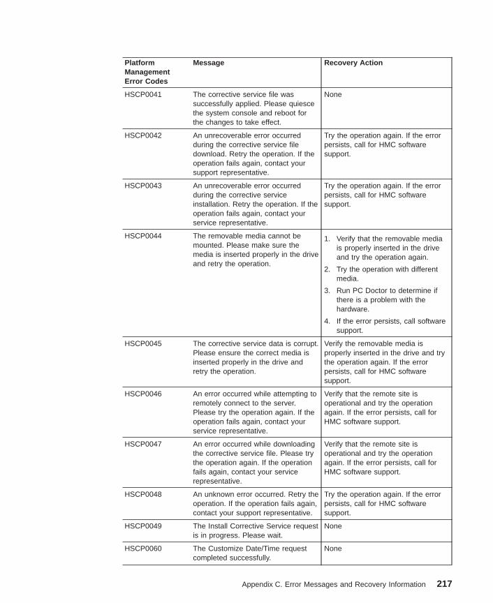
PlatformManagementError Codes
Message Recovery Action
HSCP0041 The corrective service file wassuccessfully applied. Please quiescethe system console and reboot forthe changes to take effect.
None
HSCP0042 An unrecoverable error occurredduring the corrective service filedownload. Retry the operation. If theoperation fails again, contact yoursupport representative.
Try the operation again. If the errorpersists, call for HMC softwaresupport.
HSCP0043 An unrecoverable error occurredduring the corrective serviceinstallation. Retry the operation. If theoperation fails again, contact yourservice representative.
Try the operation again. If the errorpersists, call for HMC softwaresupport.
HSCP0044 The removable media cannot bemounted. Please make sure themedia is inserted properly in the driveand retry the operation.
1. Verify that the removable mediais properly inserted in the driveand try the operation again.
2. Try the operation with differentmedia.
3. Run PC Doctor to determine ifthere is a problem with thehardware.
4. If the error persists, call softwaresupport.
HSCP0045 The corrective service data is corrupt.Please ensure the correct media isinserted properly in the drive andretry the operation.
Verify the removable media isproperly inserted in the drive and trythe operation again. If the errorpersists, call for HMC softwaresupport.
HSCP0046 An error occurred while attempting toremotely connect to the server.Please try the operation again. If theoperation fails again, contact yourservice representative.
Verify that the remote site isoperational and try the operationagain. If the error persists, call forHMC software support.
HSCP0047 An error occurred while downloadingthe corrective service file. Please trythe operation again. If the operationfails again, contact your servicerepresentative.
Verify that the remote site isoperational and try the operationagain. If the error persists, call forHMC software support.
HSCP0048 An unknown error occurred. Retry theoperation. If the operation fails again,contact your support representative.
Try the operation again. If the errorpersists, call for HMC softwaresupport.
HSCP0049 The Install Corrective Service requestis in progress. Please wait.
None
HSCP0060 The Customize Date/Time requestcompleted successfully.
None
Appendix C. Error Messages and Recovery Information 217
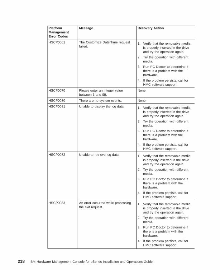
PlatformManagementError Codes
Message Recovery Action
HSCP0061 The Customize Date/Time requestfailed.
1. Verify that the removable mediais properly inserted in the driveand try the operation again.
2. Try the operation with differentmedia.
3. Run PC Doctor to determine ifthere is a problem with thehardware.
4. If the problem persists, call forHMC software support.
HSCP0070 Please enter an integer valuebetween 1 and 99.
None
HSCP0080 There are no system events. None
HSCP0081 Unable to display the log data. 1. Verify that the removable mediais properly inserted in the driveand try the operation again.
2. Try the operation with differentmedia.
3. Run PC Doctor to determine ifthere is a problem with thehardware.
4. If the problem persists, call forHMC software support.
HSCP0082 Unable to retrieve log data. 1. Verify that the removable mediais properly inserted in the driveand try the operation again.
2. Try the operation with differentmedia.
3. Run PC Doctor to determine ifthere is a problem with thehardware.
4. If the problem persists, call forHMC software support.
HSCP0083 An error occurred while processingthe exit request.
1. Verify that the removable mediais properly inserted in the driveand try the operation again.
2. Try the operation with differentmedia.
3. Run PC Doctor to determine ifthere is a problem with thehardware.
4. If the problem persists, call forHMC software support.
218 IBM Hardware Management Console for pSeries Installation and Operations Guide
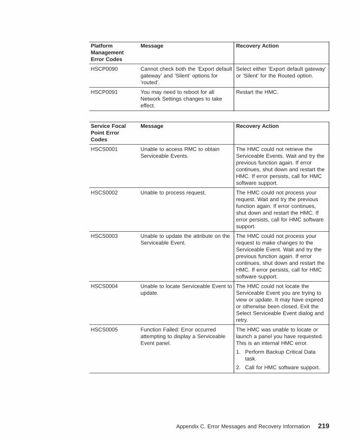
PlatformManagementError Codes
Message Recovery Action
HSCP0090 Cannot check both the ’Export defaultgateway’ and ’Silent’ options for’routed’.
Select either ’Export default gateway’or ’Silent’ for the Routed option.
HSCP0091 You may need to reboot for allNetwork Settings changes to takeeffect.
Restart the HMC.
Service FocalPoint ErrorCodes
Message Recovery Action
HSCS0001 Unable to access RMC to obtainServiceable Events.
The HMC could not retrieve theServiceable Events. Wait and try theprevious function again. If errorcontinues, shut down and restart theHMC. If error persists, call for HMCsoftware support.
HSCS0002 Unable to process request. The HMC could not process yourrequest. Wait and try the previousfunction again. If error continues,shut down and restart the HMC. Iferror persists, call for HMC softwaresupport.
HSCS0003 Unable to update the attribute on theServiceable Event.
The HMC could not process yourrequest to make changes to theServiceable Event. Wait and try theprevious function again. If errorcontinues, shut down and restart theHMC. If error persists, call for HMCsoftware support.
HSCS0004 Unable to locate Serviceable Event toupdate.
The HMC could not locate theServiceable Event you are trying toview or update. It may have expiredor otherwise been closed. Exit theSelect Serviceable Event dialog andretry.
HSCS0005 Function Failed: Error occurredattempting to display a ServiceableEvent panel.
The HMC was unable to locate orlaunch a panel you have requested.This is an internal HMC error.
1. Perform Backup Critical Datatask.
2. Call for HMC software support.
Appendix C. Error Messages and Recovery Information 219
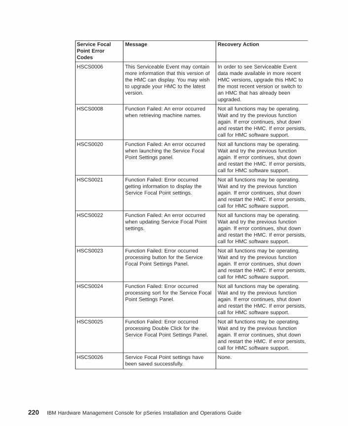
Service FocalPoint ErrorCodes
Message Recovery Action
HSCS0006 This Serviceable Event may containmore information that this version ofthe HMC can display. You may wishto upgrade your HMC to the latestversion.
In order to see Serviceable Eventdata made available in more recentHMC versions, upgrade this HMC tothe most recent version or switch toan HMC that has already beenupgraded.
HSCS0008 Function Failed: An error occurredwhen retrieving machine names.
Not all functions may be operating.Wait and try the previous functionagain. If error continues, shut downand restart the HMC. If error persists,call for HMC software support.
HSCS0020 Function Failed: An error occurredwhen launching the Service FocalPoint Settings panel.
Not all functions may be operating.Wait and try the previous functionagain. If error continues, shut downand restart the HMC. If error persists,call for HMC software support.
HSCS0021 Function Failed: Error occurredgetting information to display theService Focal Point settings.
Not all functions may be operating.Wait and try the previous functionagain. If error continues, shut downand restart the HMC. If error persists,call for HMC software support.
HSCS0022 Function Failed: An error occurredwhen updating Service Focal Pointsettings.
Not all functions may be operating.Wait and try the previous functionagain. If error continues, shut downand restart the HMC. If error persists,call for HMC software support.
HSCS0023 Function Failed: Error occurredprocessing button for the ServiceFocal Point Settings Panel.
Not all functions may be operating.Wait and try the previous functionagain. If error continues, shut downand restart the HMC. If error persists,call for HMC software support.
HSCS0024 Function Failed: Error occurredprocessing sort for the Service FocalPoint Settings Panel.
Not all functions may be operating.Wait and try the previous functionagain. If error continues, shut downand restart the HMC. If error persists,call for HMC software support.
HSCS0025 Function Failed: Error occurredprocessing Double Click for theService Focal Point Settings Panel.
Not all functions may be operating.Wait and try the previous functionagain. If error continues, shut downand restart the HMC. If error persists,call for HMC software support.
HSCS0026 Service Focal Point settings havebeen saved successfully.
None.
220 IBM Hardware Management Console for pSeries Installation and Operations Guide
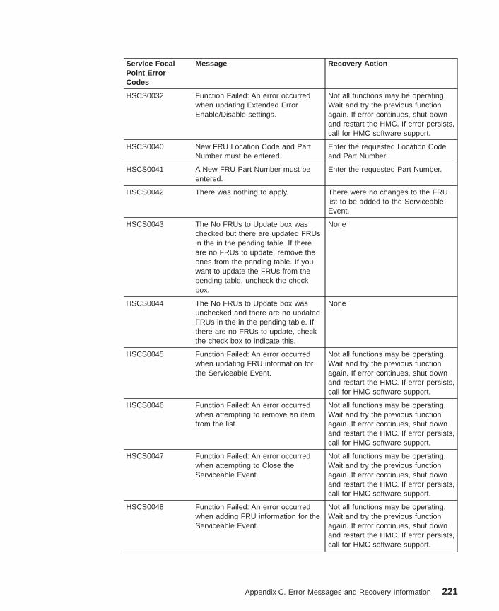
Service FocalPoint ErrorCodes
Message Recovery Action
HSCS0032 Function Failed: An error occurredwhen updating Extended ErrorEnable/Disable settings.
Not all functions may be operating.Wait and try the previous functionagain. If error continues, shut downand restart the HMC. If error persists,call for HMC software support.
HSCS0040 New FRU Location Code and PartNumber must be entered.
Enter the requested Location Codeand Part Number.
HSCS0041 A New FRU Part Number must beentered.
Enter the requested Part Number.
HSCS0042 There was nothing to apply. There were no changes to the FRUlist to be added to the ServiceableEvent.
HSCS0043 The No FRUs to Update box waschecked but there are updated FRUsin the in the pending table. If thereare no FRUs to update, remove theones from the pending table. If youwant to update the FRUs from thepending table, uncheck the checkbox.
None
HSCS0044 The No FRUs to Update box wasunchecked and there are no updatedFRUs in the in the pending table. Ifthere are no FRUs to update, checkthe check box to indicate this.
None
HSCS0045 Function Failed: An error occurredwhen updating FRU information forthe Serviceable Event.
Not all functions may be operating.Wait and try the previous functionagain. If error continues, shut downand restart the HMC. If error persists,call for HMC software support.
HSCS0046 Function Failed: An error occurredwhen attempting to remove an itemfrom the list.
Not all functions may be operating.Wait and try the previous functionagain. If error continues, shut downand restart the HMC. If error persists,call for HMC software support.
HSCS0047 Function Failed: An error occurredwhen attempting to Close theServiceable Event
Not all functions may be operating.Wait and try the previous functionagain. If error continues, shut downand restart the HMC. If error persists,call for HMC software support.
HSCS0048 Function Failed: An error occurredwhen adding FRU information for theServiceable Event.
Not all functions may be operating.Wait and try the previous functionagain. If error continues, shut downand restart the HMC. If error persists,call for HMC software support.
Appendix C. Error Messages and Recovery Information 221
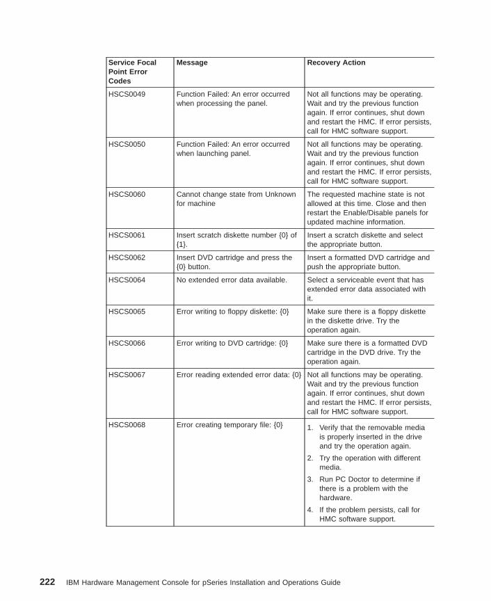
Service FocalPoint ErrorCodes
Message Recovery Action
HSCS0049 Function Failed: An error occurredwhen processing the panel.
Not all functions may be operating.Wait and try the previous functionagain. If error continues, shut downand restart the HMC. If error persists,call for HMC software support.
HSCS0050 Function Failed: An error occurredwhen launching panel.
Not all functions may be operating.Wait and try the previous functionagain. If error continues, shut downand restart the HMC. If error persists,call for HMC software support.
HSCS0060 Cannot change state from Unknownfor machine
The requested machine state is notallowed at this time. Close and thenrestart the Enable/Disable panels forupdated machine information.
HSCS0061 Insert scratch diskette number {0} of{1}.
Insert a scratch diskette and selectthe appropriate button.
HSCS0062 Insert DVD cartridge and press the{0} button.
Insert a formatted DVD cartridge andpush the appropriate button.
HSCS0064 No extended error data available. Select a serviceable event that hasextended error data associated withit.
HSCS0065 Error writing to floppy diskette: {0} Make sure there is a floppy diskettein the diskette drive. Try theoperation again.
HSCS0066 Error writing to DVD cartridge: {0} Make sure there is a formatted DVDcartridge in the DVD drive. Try theoperation again.
HSCS0067 Error reading extended error data: {0} Not all functions may be operating.Wait and try the previous functionagain. If error continues, shut downand restart the HMC. If error persists,call for HMC software support.
HSCS0068 Error creating temporary file: {0} 1. Verify that the removable mediais properly inserted in the driveand try the operation again.
2. Try the operation with differentmedia.
3. Run PC Doctor to determine ifthere is a problem with thehardware.
4. If the problem persists, call forHMC software support.
222 IBM Hardware Management Console for pSeries Installation and Operations Guide
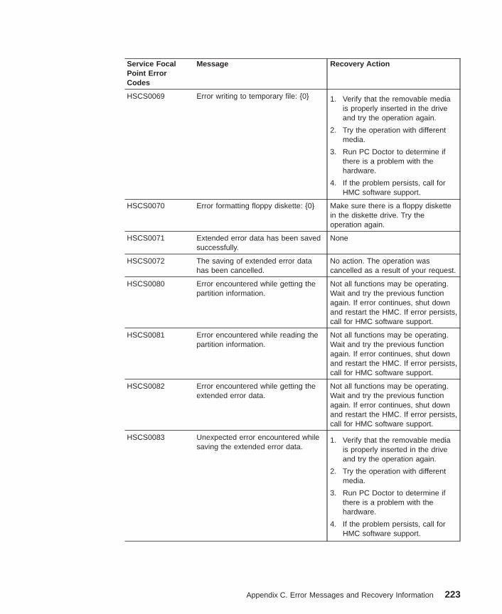
Service FocalPoint ErrorCodes
Message Recovery Action
HSCS0069 Error writing to temporary file: {0} 1. Verify that the removable mediais properly inserted in the driveand try the operation again.
2. Try the operation with differentmedia.
3. Run PC Doctor to determine ifthere is a problem with thehardware.
4. If the problem persists, call forHMC software support.
HSCS0070 Error formatting floppy diskette: {0} Make sure there is a floppy diskettein the diskette drive. Try theoperation again.
HSCS0071 Extended error data has been savedsuccessfully.
None
HSCS0072 The saving of extended error datahas been cancelled.
No action. The operation wascancelled as a result of your request.
HSCS0080 Error encountered while getting thepartition information.
Not all functions may be operating.Wait and try the previous functionagain. If error continues, shut downand restart the HMC. If error persists,call for HMC software support.
HSCS0081 Error encountered while reading thepartition information.
Not all functions may be operating.Wait and try the previous functionagain. If error continues, shut downand restart the HMC. If error persists,call for HMC software support.
HSCS0082 Error encountered while getting theextended error data.
Not all functions may be operating.Wait and try the previous functionagain. If error continues, shut downand restart the HMC. If error persists,call for HMC software support.
HSCS0083 Unexpected error encountered whilesaving the extended error data.
1. Verify that the removable mediais properly inserted in the driveand try the operation again.
2. Try the operation with differentmedia.
3. Run PC Doctor to determine ifthere is a problem with thehardware.
4. If the problem persists, call forHMC software support.
Appendix C. Error Messages and Recovery Information 223
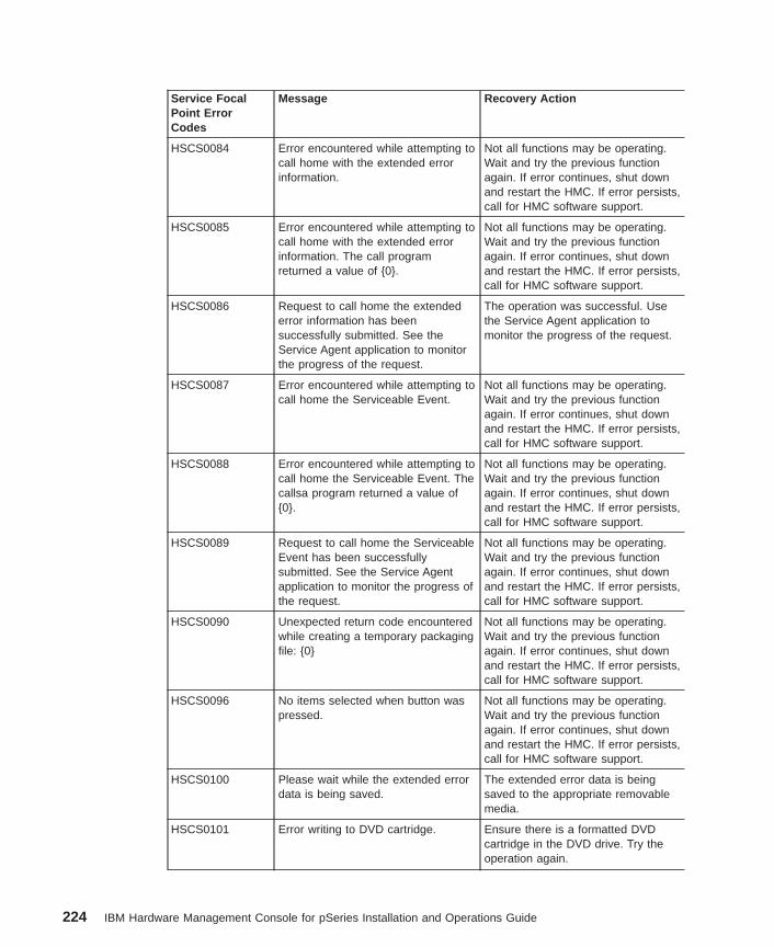
Service FocalPoint ErrorCodes
Message Recovery Action
HSCS0084 Error encountered while attempting tocall home with the extended errorinformation.
Not all functions may be operating.Wait and try the previous functionagain. If error continues, shut downand restart the HMC. If error persists,call for HMC software support.
HSCS0085 Error encountered while attempting tocall home with the extended errorinformation. The call programreturned a value of {0}.
Not all functions may be operating.Wait and try the previous functionagain. If error continues, shut downand restart the HMC. If error persists,call for HMC software support.
HSCS0086 Request to call home the extendederror information has beensuccessfully submitted. See theService Agent application to monitorthe progress of the request.
The operation was successful. Usethe Service Agent application tomonitor the progress of the request.
HSCS0087 Error encountered while attempting tocall home the Serviceable Event.
Not all functions may be operating.Wait and try the previous functionagain. If error continues, shut downand restart the HMC. If error persists,call for HMC software support.
HSCS0088 Error encountered while attempting tocall home the Serviceable Event. Thecallsa program returned a value of{0}.
Not all functions may be operating.Wait and try the previous functionagain. If error continues, shut downand restart the HMC. If error persists,call for HMC software support.
HSCS0089 Request to call home the ServiceableEvent has been successfullysubmitted. See the Service Agentapplication to monitor the progress ofthe request.
Not all functions may be operating.Wait and try the previous functionagain. If error continues, shut downand restart the HMC. If error persists,call for HMC software support.
HSCS0090 Unexpected return code encounteredwhile creating a temporary packagingfile: {0}
Not all functions may be operating.Wait and try the previous functionagain. If error continues, shut downand restart the HMC. If error persists,call for HMC software support.
HSCS0096 No items selected when button waspressed.
Not all functions may be operating.Wait and try the previous functionagain. If error continues, shut downand restart the HMC. If error persists,call for HMC software support.
HSCS0100 Please wait while the extended errordata is being saved.
The extended error data is beingsaved to the appropriate removablemedia.
HSCS0101 Error writing to DVD cartridge. Ensure there is a formatted DVDcartridge in the DVD drive. Try theoperation again.
224 IBM Hardware Management Console for pSeries Installation and Operations Guide
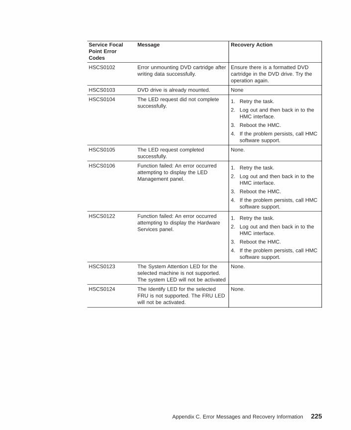
Service FocalPoint ErrorCodes
Message Recovery Action
HSCS0102 Error unmounting DVD cartridge afterwriting data successfully.
Ensure there is a formatted DVDcartridge in the DVD drive. Try theoperation again.
HSCS0103 DVD drive is already mounted. None
HSCS0104 The LED request did not completesuccessfully.
1. Retry the task.
2. Log out and then back in to theHMC interface.
3. Reboot the HMC.
4. If the problem persists, call HMCsoftware support.
HSCS0105 The LED request completedsuccessfully.
None.
HSCS0106 Function failed: An error occurredattempting to display the LEDManagement panel.
1. Retry the task.
2. Log out and then back in to theHMC interface.
3. Reboot the HMC.
4. If the problem persists, call HMCsoftware support.
HSCS0122 Function failed: An error occurredattempting to display the HardwareServices panel.
1. Retry the task.
2. Log out and then back in to theHMC interface.
3. Reboot the HMC.
4. If the problem persists, call HMCsoftware support.
HSCS0123 The System Attention LED for theselected machine is not supported.The system LED will not be activated
None.
HSCS0124 The Identify LED for the selectedFRU is not supported. The FRU LEDwill not be activated.
None.
Appendix C. Error Messages and Recovery Information 225
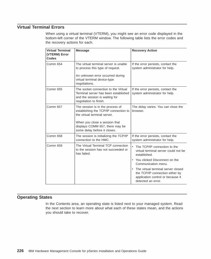
Virtual Terminal ErrorsWhen using a virtual terminal (VTERM), you might see an error code displayed in thebottom-left corner of the VTERM window. The following table lists the error codes andthe recovery actions for each.
Virtual Terminal(VTERM) ErrorCodes
Message Recovery Action
Comm 654 The virtual terminal server is unableto process this type of request.
An unknown error occurred duringvirtual terminal device-typenegotiations.
If the error persists, contact thesystem administrator for help.
Comm 655 The socket connection to the VirtualTerminal server has been establishedand the session is waiting fornegotiation to finish.
If the error persists, contact thesystem administrator for help.
Comm 657 The session is in the process ofestablishing the TCP/IP connection tothe virtual terminal server.
When you close a session thatdisplays COMM 657, there may besome delay before it closes.
The delay varies. You can close thebrowser.
Comm 658 The session is initializing the TCP/IPconnection to the HMC.
If the error persists, contact thesystem administrator for help.
Comm 659 The Virtual Terminal TCP connectionto the session has not succeeded orhas failed.
v The TCP/IP connection to thevirtual terminal server could not beestablished.
v You clicked Disconnect on theCommunication menu.
v The virtual terminal server closedthe TCP/IP connection either byapplication control or because itdetected an error.
Operating StatesIn the Contents area, an operating state is listed next to your managed system. Readthe next section to learn more about what each of these states mean, and the actionsyou should take to recover.
226 IBM Hardware Management Console for pSeries Installation and Operations Guide
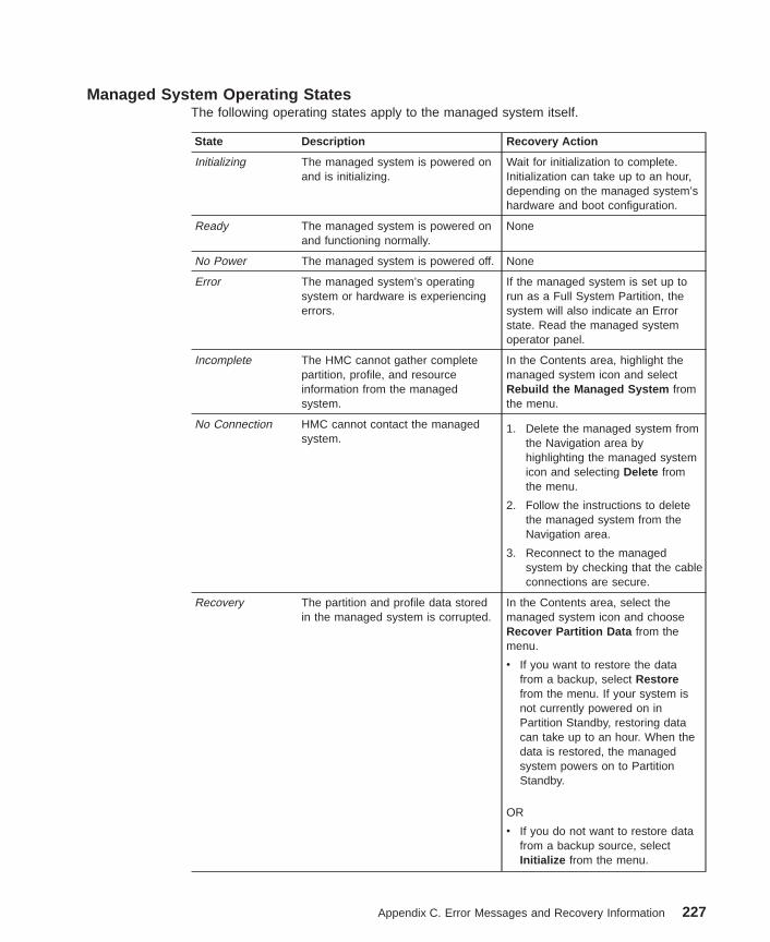
Managed System Operating StatesThe following operating states apply to the managed system itself.
State Description Recovery Action
Initializing The managed system is powered onand is initializing.
Wait for initialization to complete.Initialization can take up to an hour,depending on the managed system’shardware and boot configuration.
Ready The managed system is powered onand functioning normally.
None
No Power The managed system is powered off. None
Error The managed system’s operatingsystem or hardware is experiencingerrors.
If the managed system is set up torun as a Full System Partition, thesystem will also indicate an Errorstate. Read the managed systemoperator panel.
Incomplete The HMC cannot gather completepartition, profile, and resourceinformation from the managedsystem.
In the Contents area, highlight themanaged system icon and selectRebuild the Managed System fromthe menu.
No Connection HMC cannot contact the managedsystem.
1. Delete the managed system fromthe Navigation area byhighlighting the managed systemicon and selecting Delete fromthe menu.
2. Follow the instructions to deletethe managed system from theNavigation area.
3. Reconnect to the managedsystem by checking that the cableconnections are secure.
Recovery The partition and profile data storedin the managed system is corrupted.
In the Contents area, select themanaged system icon and chooseRecover Partition Data from themenu.
v If you want to restore the datafrom a backup, select Restorefrom the menu. If your system isnot currently powered on inPartition Standby, restoring datacan take up to an hour. When thedata is restored, the managedsystem powers on to PartitionStandby.
OR
v If you do not want to restore datafrom a backup source, selectInitialize from the menu.
Appendix C. Error Messages and Recovery Information 227
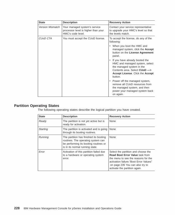
State Description Recovery Action
Version Mismatch Your managed system’s serviceprocessor level is higher than yourHMC’s code level.
Contact your service representativeto upgrade your HMC’s level so thatthe levels match.
CUoD CTA You must accept the CUoD license. To accept the license, do any of thefollowing:
v When you boot the HMC andmanaged system, click the Acceptbutton on the License Agreementpanel.
v If you have already booted theHMC and managed system, selectthe managed system in theContents area. Select CUoD —>Accept License . Click the Acceptbutton.
v Power off the managed system,remove all CUoD resources fromthe managed system, and thenpower your managed system backon again.
Partition Operating StatesThe following operating states describe the logical partition you have created.
State Description Recovery Action
Ready The partition is not yet active but isready for activation.
None
Starting The partition is activated and is goingthrough its booting routines.
None
Running The partition has finished its bootingroutines. The operating system canbe performing its booting routines oris in its normal running state.
None
Error Activation of this partition failed dueto a hardware or operating systemerror.
Select the partition and choose theRead Boot Error Value task fromthe menu to see the reasons for theactivation failure.“Boot Error Values”on page 235 You can also try to
activate the partition again.
228 IBM Hardware Management Console for pSeries Installation and Operations Guide
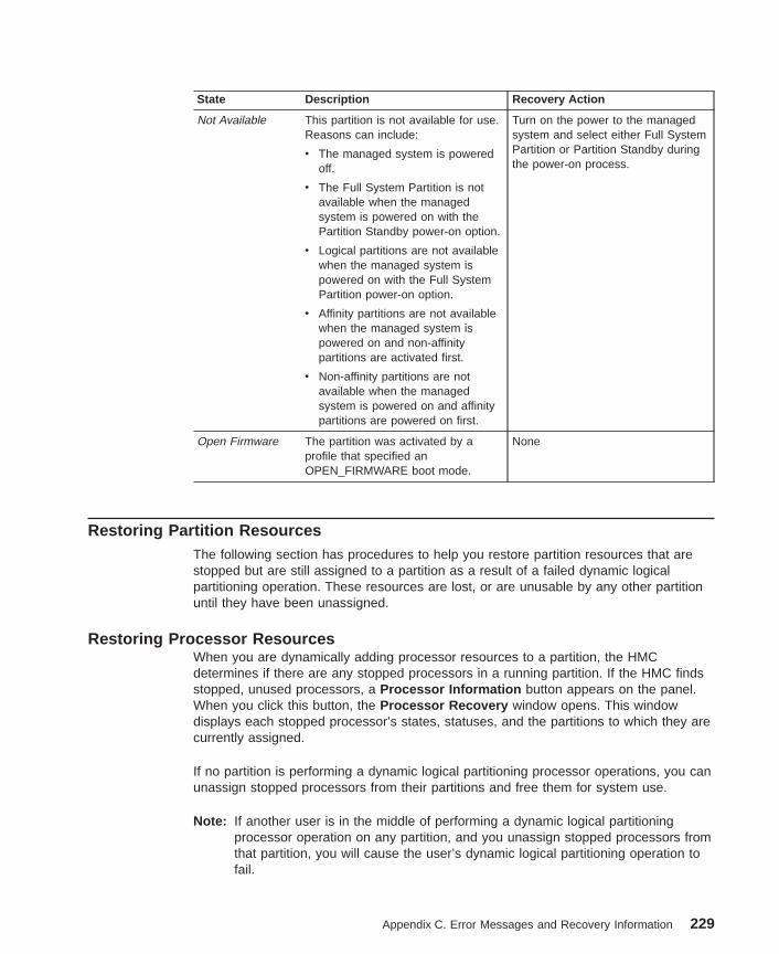
State Description Recovery Action
Not Available This partition is not available for use.Reasons can include:
v The managed system is poweredoff.
v The Full System Partition is notavailable when the managedsystem is powered on with thePartition Standby power-on option.
v Logical partitions are not availablewhen the managed system ispowered on with the Full SystemPartition power-on option.
v Affinity partitions are not availablewhen the managed system ispowered on and non-affinitypartitions are activated first.
v Non-affinity partitions are notavailable when the managedsystem is powered on and affinitypartitions are powered on first.
Turn on the power to the managedsystem and select either Full SystemPartition or Partition Standby duringthe power-on process.
Open Firmware The partition was activated by aprofile that specified anOPEN_FIRMWARE boot mode.
None
Restoring Partition ResourcesThe following section has procedures to help you restore partition resources that arestopped but are still assigned to a partition as a result of a failed dynamic logicalpartitioning operation. These resources are lost, or are unusable by any other partitionuntil they have been unassigned.
Restoring Processor ResourcesWhen you are dynamically adding processor resources to a partition, the HMCdetermines if there are any stopped processors in a running partition. If the HMC findsstopped, unused processors, a Processor Information button appears on the panel.When you click this button, the Processor Recovery window opens. This windowdisplays each stopped processor’s states, statuses, and the partitions to which they arecurrently assigned.
If no partition is performing a dynamic logical partitioning processor operations, you canunassign stopped processors from their partitions and free them for system use.
Note: If another user is in the middle of performing a dynamic logical partitioningprocessor operation on any partition, and you unassign stopped processors fromthat partition, you will cause the user’s dynamic logical partitioning operation tofail.
Appendix C. Error Messages and Recovery Information 229
To unassign stopped processors, do the following:
1. Log in to the HMC using either the System Administrator or Advanced Operatorroles.
2. In the Navigation area, click the console’s icon to expand the tree.
3. In the Navigation area, click the Server and Partition folder.
4. In the Contents area, click the Server Management icon.
5. In the Contents area, click the managed system’s icon to expand the tree.
6. Select the partition to which you want to add the processors.
7. From the Selected menu, select Dynamic Logical Partitioning .
8. Select Processors .
9. The Dynamic Logical Partitioning window opens. Click Add resources to thispartition .
10. If the Processor Information button appears underneath the Number of CPUs toadd field, the HMC has discovered stopped processors on running partitions thatyou might be able to unassign, or free for system use. If the ProcessorInformation button appears, click it. If it does not, you do not have processorresources to restore.
11. The Restore Processors window opens. This window displays each lostprocessor, along with the processor’s state, status, and partition assignment.Select the processor you want to free and click Unassign . The processors youselected are then unassigned and freed for other partitions to use.
Restoring Adapter ResourcesWhen you are dynamically adding adapter resources to a partition, the HMC determinesif there are any stopped adapters in any running partition. If the HMC finds stopped,unused adapters, an Adapter Information button appears on the panel. When youclick this button, the Restore Adapters window opens. This window displays eachstopped adapter’s state, status, and the partition to which it is assigned. If another useris not performing a dynamic logical partition operation, you can unassign stoppedadapters from their partitions and free them for system use.
Note: If another user is in the middle of performing a dynamic logical partitioningadapter operation on any partition, and you unassign stopped adapters from thatpartition, you will cause the user’s dynamic logical partitioning operation to fail.
To unassign stopped adapters from a running partition, do the following:
1. Log in to the HMC using either the System Administrator or Advanced Operatorroles.
2. In the Navigation area, click the console’s icon to expand the tree.
3. In the Navigation area, click the Server and Partition folder.
4. In the Contents area, click the Server Management icon.
5. In the Contents area, click the managed system’s icon to expand the tree.
6. Select the partition to which you want to add the processors.
7. From the Selected menu, select Dynamic Logical Partitioning .
230 IBM Hardware Management Console for pSeries Installation and Operations Guide
8. Select Adapters .
9. The Dynamic Logical Partitioning window opens. Click Add resources to thispartition .
10. If the Adapter Information button appears underneath the Adapters to add field,the HMC has discovered stopped processors on running partitions that you mightbe able to unassign, or free for system use. If the Adapter Information buttonappears, click it. If it does not, you do not have adapter resources to restore.
11. The Adapter Recovery window opens. This window displays each lost adapter,along with the adapter’s drawer, slot, type, state, and partition assignment. If youare sure that another user is not currently performing a dynamic logical partitioningoperation, select the adapter you want to free and click Unassign . The adaptersyou selected are then unassigned and freed for system use.
Restoring Memory ResourcesWhen you are dynamically adding, removing, or moving memory resources to apartition, the HMC determines if there is an inconsistency between the amount ofmemory being used by the partition and the amount of memory requested by thepartition for pending memory changes.
If these amounts are not equal, a Memory Information button appears on the window.When you click this button, the Restore Memory window opens. This window displayseach running partition’s amount of memory in use, requested memory amount, themaximum and minumum profile memory values, and the total available system memory.If another user is not performing any dynamic logical partitioning memory operations,you can correct a partition’s requested memory value amount so that it is equal to thememory amount currently in use. If the requested memory value is greater than theamount of memory actually in use, a correction of the requested memory amount willresult in some memory being freed for other partitions to use. If another user is in themiddle of performing a dynamic logical partitioning memory operation on a partition, andyou correct the requested memory amount for that partition, you will cause the otheruser’s dynamic logical partitioning operation to fail.
To correct requested memory amounts, do the following:
1. Log in to the HMC using either the System Administrator or Advanced Operatorroles.
2. In the Navigation area, click the console’s icon to expand the tree.
3. In the Navigation area, click the Server and Partition folder.
4. In the Contents area, click the Server Management icon.
5. In the Contents area, click the managed system’s icon to expand the tree.
6. Select the partition to which you want to add the processors.
7. From the Selected menu, select Dynamic Logical Partitioning .
8. Select Memory .
9. The Dynamic Logical Partitioning window opens. Click Add resources to thispartition .
Appendix C. Error Messages and Recovery Information 231
10. If the Memory Information button appears underneath the Destination PartitionDetails field, the HMC has discovered memory inconsistencies. If the MemoryInformation button appears, click it. If it does not appear, you do not havememory resources to restore.
11. The Restore Memory window opens. This window displays the name of thepartition that has the inconsistency, the amount of memory in use by this partition,the requested memory amount, this partition’s minimum and maximum memoryamounts, and the amount of free (system available) memory. Select the partition orpartitions you want to correct, and click Correct Requested Value . The memoryamount is then corrected and the Dynamic Memory Configuration window isupdated with the new values.
Error Recovery ActionsThe recovery action for many error messages is to perform a rebuild managed systemoperation. This section has procedures to help rebuild a managed system. Referencesto this procedure are indicated throughout the error message tables as appropriate.
Rebuild is Indicated for Managed SystemFor messages that indicate that a rebuild managed system operation is needed, do thefollowing to be sure that the operation is necessary:
1. Verify you have the correct authority to perform the task.
v If you do not, log in with the correct user authority and try the task again.
v If you do have the correct authority, retry the task. If it still fails, continue withstep 2.
2. Perform the Rebuild Managed System task (see “Steps to Rebuild a ManagedSystem”) then retry the failing task. If the task still fails, continue with step 3.
3. Reboot the HMC, then verify that the managed system is in Ready state.
v If the managed system is in Ready state, retry the failing task. If the task stillfails, call for HMC software support.
v If the managed system is in any state other than Ready, (for example, not inConnection state, Error state, or another state) refer to “Managed System Statesfor the HMC” on page 234 for the recovery procedure for the current state.
Steps to Rebuild a Managed SystemTo rebuild a managed system, do the following:
1. In the HMC contents area, select the managed system that you want to rebuild.
2. Select Rebuild Managed System from the Select menu or by clicking the rightmouse button in the content area.
3. A confirmation window displays a message asking you to confirm whether you wantto perform this task.
While this task is running, you cannot perform any other HMC functions. This taskcan take up to several minutes to complete.
232 IBM Hardware Management Console for pSeries Installation and Operations Guide
Steps for Rebooting the HMCTo reboot the HMC, do the following:
1. From the Select menu, select Console .
2. Select Exit .
3. When you exit from your HMC session, you can choose to shut down, reboot, orlogout from your session. Using the pulldown bar, select reboot .
4. Select Exit . The HMC reboots.
Performing a File System Check on HMC RebootIn the event of an unexpected power loss or if the white reset button on the HMC ispressed, the system runs a file system check (fsck) on the next system reboot. If theautomatic file system check fails, the HMC prompts the user to enter the HMC’s rootpassword so that it can perform a manual file system maintenance operation. If thefollowing message displays: Enter the root password or hit Control-D to reboot.,do the following to recover the HMC:
1. Type the following root password: passw0rd
2. To run a file-system check, type fsck <file system> where <file system> is thename of the file system that fails the file system check, such as / and /var in thefield. When the checking is done, a prompt window opens.
3. Type reboot
OR
Press Ctrl-D to reboot the HMC interface.
Changing a Partition Host Name ManuallyIf you need to change the host name of the partition manually, before changing the hostname of the partition, do the following:
1. Run the following command: /usr/sbin/rsct/bin/runact -c IBM.ManagementServerSetRTASPollingInterval Seconds=0 (Skip this step if the AIX level is below 51D.)
2. Run the following command: /usr/sbin/rsct/bin/lsrsrc IBM.ManagementServerHostname
The output displayed will be similar to the following: (If the partition is managed bymultiple HMCs, there may be multiple entries, since each HMC has its own entry.)
resource 1: Hostname = "hmc1.mydomain.mycompany.com"
3. For each entry, remove the resource using the host name shown. For example, typethe following: /usr/sbin/rsct/bin/rmrsrc -s’Hostname =″hmc1.mydomain.mycompany.com ″’ IBM.ManagementServer . You can verifythat all entries have been removed by performing Step 2 again.
4. Run the following command: /usr/sbin/rsct/bin/rmcctrl -z
5. Change the host name of the partition.
6. Once the host name has been changed, run the following command:/usr/sbin/rsct/bin/rmcctrl -A
Appendix C. Error Messages and Recovery Information 233
Managed System States for the HMCThis section describes the states for a managed system that display on the HMC.Follow the procedures in this section to attempt to restore management of a system inone of the listed states.
No Connection StateThe HMC has lost contact with the managed system, or power to the service processorhas been removed. Do the following:
1. Check the operator panel on the managed system to verify that the power is on.
a. If the power light indicates that there is no power on the managed systemoperator panel, refer to the Eserver pSeries 690 User’s Guide forproblem-determination procedures.
b. After power is restored, wait 5 minutes for the service processor to re-IPL andthe HMC to re-establish contact. If the HMC can access partitions using a virtualterminal (VTERM) but the state is still No Connection, call for HMC support.
2. If the power indicator is on, wait 5 minutes for the HMC to attempt to reestablishcontact. The service processor in the managed system may be in the process ofturning power on. If partitions no longer respond, the system power is off.
3. From a telnet session from another system, attempt to ping or contact activepartitions on this managed system.
If the partitions are active, do the following:
a. Verify that the serial cable on the HMC is firmly connected and that it is notdamaged.
b. Reboot the HMC.
c. Reset the Service Processor.
4. If the managed system is running and restarting the HMC did not resolve theproblem, call for HMC software support.
Incomplete StateThe HMC is unable to collect information required to build a complete representation ofthe managed system. Do the following:
1. Select Rebuild Managed System from the Managed System Task list. If the stategoes to Recovery, see ″Recovery State″. If the state does not go to Recovery,continue with the next step.
Note: This operation performed in the next step may take up to ten minutes tocomplete.
2. Reboot the HMC. If state goes to Recovery, see ″Recovery State.″
If the status remains Incomplete, verify whether there is a redundant HMC andverify that no one is entering commands from the alternate HMC.
Repeat step 1. If it still fails, go to the next step.
3. Restore the profile data (see task list). The profile data restore task is a full restorefrom a backup copy.
234 IBM Hardware Management Console for pSeries Installation and Operations Guide

4. Verify that the HMC serial cable is securely attached to the HMC and that it is notdamaged.
5. Reset the service processor.
6. If the problem persists, call for service.
Recovery StateProfile data stored in the managed server has been cleared or corrupted. Do thefollowing:
1. Select the Recover partition data from the managed system task list to restore orinitialize profile data.
2. If the state changes to Incomplete, see “Incomplete State” on page 234 for recoveryprocedures.
3. If the state changes to No Connection, go to “No Connection State” on page 234 forrecovery procedures.
4. If the restore fails, reset the service processor.
5. Clear NVRAM (nonvolatile memory), and retry the recovery partition data task.
6. If the problem persists, call for HMC software support.
Error StateError state automatically generates a call to the service support center if the function isenabled. If the function is not enabled, call for HMC software support.
Open Firmware StateThe partition has been activated and is in the Open Firmware state. You can open avirtual terminal to the partition and enter open firmware commands.
Boot Error ValuesThe following table contains the boot error values and messages that might display onthe HMC if a problem occurs during the boot process and initial loading of the consolesoftware.
Boot Error Values Message
0x00 NO_ERROR
0x01 NO_GLOBAL_SERVER
0x02 NO_CONTIGUOUS_PAGE_TABLE_MEMORY
0x03 NO_CONTIGUOUS_REAL_MODE_MEMORY
0x04 NOT_ENOUGH_PARTITION_LOGICAL_MEMORY
0x05 ALL_ASSIGNED_PROCESORS_ARE_NOT_WORKING
0x06 NO_PROCESSORS_ASSIGNED
0x07 INVALID_PROCESSOR_ASSIGNED_FOR_ALPAR_PARTITION
0x08 NO_MEMORY_AVAILABLE_FOR_ALPAR_PARTITIONS
0x60 ANOTHER_SERVICE_AUTHORITY_PARTITION_IS_ACTIVE
Appendix C. Error Messages and Recovery Information 235

Boot Error Values Message
0x7F FAIL_TO_BOOT
0x80 I/O_SLOT_ASSIGNMENT_ERROR
0xAC AIX_OS_TERM_WITH_CRASH_CODE
236 IBM Hardware Management Console for pSeries Installation and Operations Guide
Releasing an HMC Lock on the Managed SystemIf you have two HMCs connected to your managed system, one HMC temporarily locksthe other out while it is performing operations. This action prevents the other HMC fromoperating on the managed system because simultaneous operations could causeconflicting results. If the interface is locked, most console operations automatically waitfor the lock to release.
However, in the rare event that an HMC has a problem that prevents the lock frombeing properly released, you may need to manually unlock the connection to themanaged system. Typically, if one HMC has locked the connection, you must unlock itfrom the other HMC, which then allows other HMCs to communicate with the managedsystem and run further commands.
To release a lock on a managed system, you must be a member of one of the followingroles:
v System Administrator
v Advanced Operator
To release an HMC lock, do the following:
1. In the Contents area, select the managed system.
2. In the menu, click Selected .
3. Select Release Console Lock .
Appendix C. Error Messages and Recovery Information 237

238 IBM Hardware Management Console for pSeries Installation and Operations Guide
Index
Aactivating
partitions 104specific partition profile 104system profiles 125
adaptersadding to partitions dynamically 109moving between partitions dynamically 114removing from partitions dynamically 118
addingFRUs 151IP addresses and host names 43serviceable event comments 149
affinity partitionsactivating 104assignable resources 26changing default profiles 122copying profiles 122creating 102creating additional profiles 120deleting 119deleting profiles 123profiles 120understanding boot errors 122updating 103viewing profile properties 121
application overview 31automatic call home
overview 146
Bbacking up
critical console data 133profile data 85restore options 86
backupsscheduling 45
boot error values 235boot errors
understanding 122
Ccabling
connecting the LAN cable 11power cord 11the HMC 7
changingIP addresses and host names 43passwords 79the predefined HMC root password 12
changing keyboard settings 12
checkingHMC software level 13
closinga virtual terminal window 131
command lineexamples of scripts 158high-level 153
commandsenabling and disabling remote 47using 153
configuringservice agent 139system manager security 59
console eventsviewing 40
console menu 34contents area
description 30copying
default partition profiles 122partition profiles 122system profiles 124
copying text in a virtual terminal window 130corrective service
installing 134creating
additional partition profiles 120partitions 99system profiles 123users 77
critical console databacking up 133
customizingnetwork settings 40
Ddate and time
setting 39default
user ID and password 12deleting
affinity partitions 119logical partitions 119managed system 87partition profiles 123system profiles 124users 78
device attributes, setting 44documentation browser 35domain names
setting 42
239
downloadcorrective service 134
dynamic logical partitioningadding adapters 109adding memory 107dynamically reassigning resources 105moving adapters 114moving memory 113moving resources 111removing adapters 118removing memory 117removing processors 115
dynamically reassigning resourcesProcessors 105
Eediting
user information 78environment
system management 30error messages 165
perform a file system check indicated 233reboot the HMC indicated 233rebuild managed system indicated 232backup and restore 197CIMOM 202HMC 203inventory scout 165managed system 178, 214managed system resource 182operating system reset 195panel 204partition 185profile 191profile data 170recovery actions 232service focal point 219system profile 193unity class 201user management 205virtual terminal 196, 226
errorsvirtual terminal 226
extended error datamanaging 149
Ffirst-time login procedures 29fixes, downloading and installing 134frame management 89
deactivating a CSP 91installing corrective service 136powering off a frame’s I/O drawers 92powering on the frame 90receiving corrective service 135
frame management (continued)resetting a CSP 91viewing frame properties 90
FRUupdating information 150
FRU identity LEDsactivating 151deactivating 151
FRUsadding 151replacing 150
full system partition 19, 82power on diagnostic default boot list description 83power on diagnostic stored boot list description 83power on normal description 83power on option descriptions 82power on power on open firmware OK prompt
description 83power on SMS description 83tasks 81
Hhardware service functions 151
activating and deactivating FRU identity LEDs 151help menu 35high-level command line 153HMC
introduction 5HMC environment 29HMC lock
releasing 88, 237host names
adding and changing 43setting 43
hscroot passwordchanging 12
Iinstalling
AIX in full system partition 129AIX on a partition 130connecting the external modem 10connecting the LAN cable 11HMC interface on a new hard disk 13plugging in the power cord 11the HMC hardware 7the monitor 7the remote client on a Linux system 54the remote client on a Windows system 53
instatingconnecting the cables 7
inventory scout 65collecting data for microcode discovery service 67collecting vital product data 67restarting 68
240 IBM Hardware Management Console for pSeries Installation and Operations Guide
inventory scout (continued)setting up for a managed system 65setting up for a partition 65using the configuration assistant 65
inventory scout servicesoverview 33
IP addressesadding and changing 43setting 42
Kkeyboard
control 35
LLAN cable
connecting 11language
changing HMC interface 50laser compliance statement xlaser safety information xlocale
changing 50logging in to the HMC for the first time 12logging out of the HMC 29logical partition
operating states 28logical partitions
activating 104activating system profiles 125activating system profiles when other partition profiles
are running 125adding adapters dynamically 109adding memory dynamically 107adding processors dynamically 105affinity partition assignable resources 26assignable resources 23assigning a host name 26changing default profiles 122concepts 18configuring inventory scout for 65copying profiles 122copying system profiles 124creating 99creating additional affinity partition profiles 120creating additional profiles 120creating affinity 102creating system profiles 123deleting 119deleting affinity partitions 119deleting profiles 123deleting system profiles 124dynamically reassigning resources 105full system 82managed system description 20
logical partitions (continued)managing affinity partition profiles 120managing system profiles 123memory overhead 23modifying system profile properties 124moving adapters dynamically 114moving memory dynamically 113moving processors dynamically 111operating states 228partition description 20performing soft and hard resets in 120power on diagnostic default boot list description 83power on diagnostic stored boot list description 83power on normal description 83power on option 82power on option descriptions 82power on power on open firmware OK prompt
description 83power on SMS description 83powering on using a system profile 125preparing for 23profiles 21, 120removing adapters dynamically 118removing memory dynamically 117removing processors dynamically 115requirements 23resetting the operating system on 89restarting the operating system in 120RMO memory considerations 25scenarios 19setting service authority in 121system profiles 21understanding boot errors 122updating affinity 103validating system profiles 125viewing profile properties 121viewing system profile properties 124
login procedures 29
Mmanaged system
error state 235incomplete state 234no connection state 234open firmware state 235recovery state 235collecting VPD data 67deactivating a CSP 91deleting from the contents area 87description 20error messages 214managing a frame of managed resources 89, 90operating states 27, 226powering off 84powering off a frame’s I/O drawers 92
Index 241
managed system (continued)powering on 82rebuilding information about 87releasing lock 88resetting a CSP 91setting policies 84setting up inventory scout 65states 234tasks 81using multiple 31viewing frame properties 90viewing properties 84
managingextended error data 149
memoryadding to partitions dynamically 107moving between partitions dynamically 113removing from partitions dynamically 117
menu options 34console 34help 35object 35selected 35view 35window 35
microcode discovery servicecollecting data for 67
modemconnecting 10
modespartition 82
modes of operation 5modifying
partition profile properties 121system profiles 124
more than one HMC 69multiple HMCs
using 30
Nnavigation area
description 30network
adding and changing IP addresses and hostnames 43
customizing settings 40setting device attributes 44setting domain names 42setting host names 43setting IP addresses 42setting routing information 44testing connectivity 45using adapters to communicate with partitions 41
noticessafety ix
Oobject menu 35online HMC publications 35online publications xiopening
a virtual terminal window 128operating modes 5operating states
error 235HMC 234incomplete 234managed system 27, 226no connection 234overview 27partition 28, 228recovery 235recovery information 226
operating systemrestarting in a partition 120
overviewapplication 31HMC 5inventory scout services application 33problem determination application 33server management application 31service agent 33service focal point 34, 145software maintenance 32system configuration 32, 39system manager security 31user management application 32
Ppartition
activating 104adding adapters dynamically 109, 118adding memory dynamically 107, 117adding processors dynamically 105changing default profiles 122copying profiles 122creating 99creating additional profiles 120creating logical 99deleting profiles 123dynamically reassigning resources 105full system 19, 82modes 82moving adapters dynamically 114moving memory dynamically 113moving processors dynamically 111naming the host name 26operating states 28, 228preparing 23preparing your system for 99profiles 21, 120
242 IBM Hardware Management Console for pSeries Installation and Operations Guide
partition (continued)reactivating with a partition profile 105removing processors dynamically 115requirements 23resetting the operating system on 89resources 23understanding boot errors 122viewing profile properties 121
partition management application 81tasks 99
partition profileactivating 104changing defaults 122copying 122modifying properties 121viewing properties 121
partitionsdynamically reassigning resources 105
passwordchanging 79changing root 12
pasting text in a virtual terminal window 130policy settings
description 84power cords
plugging in 11power on diagnostic default boot list 83power on diagnostic stored boot list 83power on open firmware OK prompt 83power on options 82
power on diagnostic default boot list 83power on diagnostic stored boot list 83power on normal 83power on open firmware OK prompt 83power on SMS 83
power on SMS 83powering off
managed system 84system after all logical partitions are powered off 84
powering onthe managed system 82using a system profile 125
predefined user and password 29preparing for logical partitioning 23problem determination
overview 33processors
adding to partitions dynamically 105moving between partitions dynamically 111removing from partitions dynamically 115
profilesystem 123
profilesbacking up profile data 85initializing data 86
profiles (continued)logical partition 21managing data 85partition 120removing data 86restoring profile data 85, 86system 21
publications, online xi
Rreactivating
a partition with a partition profile 105rebooting the HMC 29rebuilding the managed system 87recover information
incomplete state 234recovery information 165
error 232error state 235managed system operating states 226operating states 226, 228rebooting the HMC 233rebuilding a managed system 232recovery state 235virtual terminal errors 226
redundant HMCs 69releasing an HMC lock on the managed system 88remote client 53
installation on a Windows system 53installation requirements 53installing on a Linux system 54installing security 55installing security on a Linux system 56installing security on a Windows system 55uninstallating from a Linux system 55uninstalling from a Windows system 54uninstalling security 57uninstalling security from a Linux system 57uninstalling security from a Windows system 56
remote client securityconfiguring 57installation requirements 53installing 55installing on a Linux system 56installing on a Windows system 55uninstalling from a Linux system 57uninstalling from a Windows system 56
remote commandsenabling and disabling 47
remote connections 161using scripts 161
remote virtual terminal connectionsenabling 50
removable mediaformatting 135
Index 243
replacingFRUs 150
resetssoft and hard 120
resettingoperating system on a partition 89
restartingpartition operating systems 120
restore informationoperating states 234
restorey informationno connection state 234
restoringprofile data 85profile data options 86
reviewingscheduled backup 46
rolesand task descriptions 71overview 71
root passwordchanging 12
routing informationchanging 44deleting 44entering new 44setting 44
Ssafety notices ix
laser compliance statement xsaving
upgrade data 134scheduled backup
reviewing 46viewing 46
schedulingbackups 45
scriptsusing to connect to the HMC remotely 161
security 57selected menu 35server management application
overview 31service agent 137
changing the mode 141configuring 139customizing and registering 139overview 33starting processes 141status indicators 142stopping processes 142stopping the user interface 141
service authoritysetting 17
service authority, setting 101, 121service focal point 6
activating and deactivating FRU identity LEDs 151adding FRUs 151call home overview 146closing a serviceable event 150enabling surveillance notifications 147error messages 219hardware service functions 151overview 34, 145replacing FRUs 150saving and managing extended error data 149serviceable events 148setting up surveillance 146settings 146testing error reporting 145updating FRU information 150viewing and adding serviceable event
comments 149viewing error details 149viewing service processor error details 149viewing serviceable event details 148viewing serviceable event partition information 151viewing serviceable events 148
service setupchecklist 17
serviceable eventviewing partition information 151
serviceable eventsadding comments 149selecting and viewing 148updating FRU information 150viewing comments 149viewing details 148viewing error details 149viewing service processor error details 149working with 148
settingdomain names 42host names 43IP addresses 42managed system policies 84routing information 44surveillance policies 84the date and time 39
setupHMC for service checklist 17
shutting down the HMC 29soft and hard resets 120software
checking current HMC OS levels 14updating the HMC OS 14upgrading the HMC 16
software levelchecking HMC 13
244 IBM Hardware Management Console for pSeries Installation and Operations Guide

software maintenanceoverview 32, 133
software versionchecking 13
statesoperating 27
system configurationcustomizing network settings 40overview 32, 39setting the date and time 39
system management environment 30system manager security
configuring a system as a secure server 61configuring for secure operation 59configuring your HMC to have certificate
authority 59configuring your servers as secure system manager
servers 60copying private key ring files to diskette 61copying the certificate authority’s public key ring file
from diskette to an HMC client 62copying the certificate authority’s public key ring file
to diskette 62distributing the certificate authority’s public key to
your clients 62generating private key ring files for your servers 60installing the private key ring file on a server 61installing the private key ring files 60overview 31viewing configuration properties 63
system profile 84powering on using 125viewing properties 124
system profiles 21activating 125activating when other partition profiles are
running 125copying 124creating 123modifying 124overview 84, 123removing data 124validating success 125
Ttasks
full system management 81partition management application 99
testingnetwork settings 45
time and datesetting 39
time rangeviewing scheduled backup 46
toolbar actions 34
Uuninstalling
the remote client from a Linux system 55the remote client from a Windows system 54
updatingfirmware 17FRU information 150
upgrade datasaving 134
userchanging passwords 79creating 77deleting 78editing information 78error messages 205predefined ID and password 29roles and tasks 72roles overview 71viewing definitions 78
user environment 29user management
changing passwords 79creating users 77deleting a user 78editing user information 78overview 32, 70roles 71roles and task table 72tasks 72viewing user properties 78
using multiple HMCs 30using multiple managed systems 31
Vvalidating that system profiles will activate 125view menu 35viewing
console events 40managed system properties 84partition profile properties 121serviceable event comments 149serviceable event details 148serviceable event error details 149serviceable event partition information 151system manager security configuration
properties 63system profile properties 124the date and time 39the scheduled backup time range 46user definitions 78
virtual terminalclosing 131copying and pasting in a window 130enabling remote connections 50errors 226
Index 245

virtual terminal (continued)in full system partition 128installing AIX in full system partition 129installing AIX on a partition 130managing AIX device drivers 128opening 128opening on a partition 128overview 125
VPDcollecting data for 67
Wwindow menu 35
246 IBM Hardware Management Console for pSeries Installation and Operations Guide

Readers’ Comments — We’d Like to Hear from You
IBM Hardware Management Console for pSeries Installation and Operations Guide
Publication No. SA38-0590-02
Overall, how satisfied are you with the information in this book?
Very Satisfied Satisfied Neutral Dissatisfied Very
Dissatisfied
Overall satisfaction h h h h h
How satisfied are you that the information in this book is:
Very Satisfied Satisfied Neutral Dissatisfied Very
Dissatisfied
Accurate h h h h h
Complete h h h h h
Easy to find h h h h h
Easy to understand h h h h h
Well organized h h h h h
Applicable to your tasks h h h h h
Please tell us how we can improve this book:
Thank you for your responses. May we contact you? h Yes h No
When you send comments to IBM, you grant IBM a nonexclusive right to use or distribute your comments in any
way it believes appropriate without incurring any obligation to you.
Name Address
Company or Organization
Phone No.
Readers’ Comments — We’d Like to Hear from YouSA38-0590-02
SA38-0590-02
Cut or FoldAlong Line
Cut or FoldAlong Line
Fold and Tape Please do not staple Fold and Tape
Fold and Tape Please do not staple Fold and Tape
NO POSTAGENECESSARYIF MAILED IN THEUNITED STATES
BUSINESS REPLY MAILFIRST-CLASS MAIL PERMIT NO. 40 ARMONK, NEW YORK
POSTAGE WILL BE PAID BY ADDRESSEE
Information DevelopmentDepartment H6DS-905-6C00611400 Burnet RoadAustin, TX 78758-3493
_ _ _ _ _ _ _ _ _ _ _ _ _ _ _ _ _ _ _ _ _ _ _ _ _ _ _ _ _ _ _ _ _ _ _ _ _ _ _ _ _ _ _ _ _ _ _ _ _ _ _ _ _ _ _ _ _ _ _ _ _ _ _ _ _ _ _ _ _ _ _ _ _ _ _ _ _
_ _ _ _ _ _ _ _ _ _ _ _ _ _ _ _ _ _ _ _ _ _ _ _ _ _ _ _ _ _ _ _ _ _ _ _ _ _ _ _ _ _ _ _ _ _ _ _ _ _ _ _ _ _ _ _ _ _ _ _ _ _ _ _ _ _ _ _ _ _ _ _ _ _ _ _ _
__
__
__
__
__
__
__
__
__
__
__
__
__
__
__
__
__
__
__
__
__
__
__
__
__
__
__
__
__
__
__
__
__
__
__
__
__
__
__
__
_


Part Number: 00P3702
Printed in U.S.A.
October 2002
SA38-0590-02
(1P)
P/N:
00P3702

Spin
einformat
ion:
IBM
Har
dwar
eM
anag
emen
tCon
sole
for
pSer
ies
Inst
alla
tion
and
Ope
ratio
nsG
uide
SA38
-059
0-02