ibm power platform reliability, availability, and … power platform reliability, availability, and...
TRANSCRIPT

IBM Power Platform Reliability, Availability, and Serviceability (RAS)
Highly Available IBM Power Systems Servers for Business-Critical Applications
By: Jim Mitchell, Daniel Henderson, George Ahrens, and Julissa Villarreal
October 8, 2008


POW03003.doc Page 3
Introduction ................................................................................................5 A RAS Design Philosophy.................................................................................................................. 6
Reliability: Start with a Solid Base ..........................................................8 Continuous Field Monitoring............................................................................................................. 10 A System for Measuring and Tracking ............................................................................................. 11
Servers Designed for Improved Availability ..........................................11 System Deallocation of Failing Elements ..........................................................................12
Persistent Deallocation of Components ........................................................................................... 12 Dynamic Processor Deallocation and Dynamic Processor Sparing ................................................ 12 POWER6 Processor Recovery ........................................................................................................ 14 Processor Instruction Retry .............................................................................................................. 14 Alternate Processor Recovery.......................................................................................................... 15 Processor Contained Checkstop...................................................................................................... 16
Protecting Data in Memory Arrays......................................................................................17 POWER6 Memory Subsystem ......................................................................................................... 20 Uncorrectable Error Handling........................................................................................................... 21 Memory Deconfiguration and Sparing.............................................................................................. 22 L3 Cache .......................................................................................................................................... 22 Array Recovery and Array Persistent Deallocation .......................................................................... 23
The Input Output Subsystem ..............................................................................................24 A Server Designed for High Bandwidth and Reduced Latency ....................................................... 24 I/O Drawer/Tower Redundant Connections and Concurrent Repair................................................ 24 GX+ Bus Adapters............................................................................................................................ 25 GX++ Adapters................................................................................................................................. 25 PCI Bus Error Recovery ................................................................................................................... 25
Additional Redundancy and Availability ............................................................................26 POWER Hypervisor.......................................................................................................................... 26 Service Processor and Clocks ......................................................................................................... 28 Node Controller Capability and Redundancy on the POWER6 595 ................................................ 28 Hot Node (CEC Enclosure or Processor Book) Add ........................................................................ 29 Cold-node Repair ............................................................................................................................. 29 Concurrent-node Repair ................................................................................................................... 30 Live Partition Mobility........................................................................................................................ 31
Availability in a Partitioned Environment...........................................................................31 Operating System Availability.............................................................................................33 Availability Configuration Options .....................................................................................34
Serviceability ............................................................................................34 Converged Service Architecture....................................................................................................... 36
Service Environments..........................................................................................................36 Service Component Definitions and Capabilities..............................................................37
Error Checkers, Fault Isolation Registers (FIR), and Who’s on First (WOF) Logic.......................... 37 First Failure Data Capture (FFDC) ................................................................................................... 38 Fault Isolation ................................................................................................................................... 38 Error Logging.................................................................................................................................... 39 Error Log Analysis ............................................................................................................................ 39

Problem Analysis ..............................................................................................................................39 Service History Log...........................................................................................................................40 Diagnostics .......................................................................................................................................40 Remote Management and Control (RMC) ........................................................................................41 Extended Error Data .........................................................................................................................42 Dumps...............................................................................................................................................42 Service Interface ...............................................................................................................................42 LightPath Service Indicator LEDs .....................................................................................................42 Guiding Light Service Indicator LEDs ...............................................................................................42 Operator Panel..................................................................................................................................43 Service Processor.............................................................................................................................43 Dedicated Service Tools (DST) ........................................................................................................44 System Service Tools (SST).............................................................................................................44 POWER Hypervisor ..........................................................................................................................45 Advanced Management Module (AMM) ...........................................................................................45 Service Documentation.....................................................................................................................46 System Support Site .........................................................................................................................47 InfoCenter – POWER5 Processor-based Service Procedure Repository ........................................47 Repair and Verify (R&V) ...................................................................................................................47 Problem Determination and Service Guide (PD&SG) ......................................................................48 Education ..........................................................................................................................................48 Service Labels ..................................................................................................................................48 Packaging for Service .......................................................................................................................48 Blind-swap PCI Adapters ..................................................................................................................49 Vital Product Data (VPD) ..................................................................................................................49 Customer Notify ................................................................................................................................49 Call Home .........................................................................................................................................50 Inventory Scout .................................................................................................................................50 IBM Service Problem Management Database..................................................................................50
Supporting the Service Environments............................................................................... 51 Stand–Alone Full System Partition Mode Environment....................................................................51 Integrated Virtualization Manager (IVM) Partitioned Operating Environment ..................................54 Hardware Management Console (HMC) Attached Partitioned Operating Environment ..................57 BladeCenter Operating Environment Overview................................................................................62
Service Summary................................................................................................................. 64
Highly Available Power Systems Servers for Business-Critical Applications ............................................................................................. 65
Appendix A: Operating System Support for Selected RAS Features..............................................66
Page 4 POW03003.doc

Introduction In April 2008, IBM announced the highest performance Power Architecture® technology-based server: the IBM Power 595, incorporating inventive IBM POWER6™ processor technology to deliver both out-standing performance and enhanced RAS capabilities. In October, IBM again expanded the product fam-ily introducing the new 16-core Power 560 and expanding the capabilities of the Power 570, increasing the cycle time and adding versions supporting up to 32 cores. The IBM Power™ Servers complement IBM’s POWER5™ processor-based server family, coupling technology innovation with new capabilities designed to help ease administrative burdens and increase system utilization. In addition, IBM PowerVM™ delivers virtualization technologies for IBM Power™ Systems product families, enabling indi-vidual servers to run dozens or even hundreds of mission-critical applications. POWER5+ Chip
Since POWER5+ is derivative of POWER5, for the purposes of this white paper, unless otherwise noted, the term “POWER5 processor-based” will be used to include technologies using either POWER5 or POWER5+ processors. Descriptions of the POWER5 processor technology are also applicable to the POWER5+ processor.
IBM POWER6 Processor Technology Using 65 nm technology, the POWER6 processor chip is slightly larger (341 mm2 Vs. 245 mm2) than the POWER5+TM microprocessor chip but delivers almost three times the number of transistors and, at 5.0 GHz, more than doubles the internal clock speed of its high-performance predecessor. Ar-chitecturally similar, POWER6, POWER5, and POWER5+ processors offer simultaneous multithreading and multi-core processor packaging. The POWER6 processors are expected to offer increased reliability and im-proved server price/performance when shipped in System p servers
POWER6 Chip
In IBM’s view, servers must be designed to avoid both planned and unplanned outages, and to maintain a focus on application uptime.
From a reliability, availability, and serviceability (RAS) standpoint, servers in the IBM Power Systems fam-ily include features designed to increase availability and to support new levels of virtualization, building upon the leading-edge RAS features delivered in the IBM eServer™ p5, pSeries® and iSeries™ families of servers.
IBM RAS engineers are constantly making incremental improvements in server design to help ensure that IBM servers support high levels of concurrent error detection, fault isolation, recovery, and availability. Each successive generation of IBM servers is designed to be more reliable than the server family it re-places. IBM has spent years developing RAS capabilities for mainframes and mission-critical servers. The POWER6 processor-based server builds on the reliability record of the POWER5 processor-based offerings.1
System p 570
middleware, solutions, services, and/or financing. Based high-performance POWER6 microprocessors, these servers are flexible, powerful choices for resource optimiza-tion, secure and dependable performance, and rapid re-sponse to changing business needs. Representing a convergence of IBM technologies, IBM Power servers deliver not only performance and price/performance advantages, they also offer powerful virtualization capabilities for UNIX®, IBM i, and Linux®1 data centers. POWER6 processors can run 64-bit applications, while con-currently supporting 32-bit applications to enhance flexibility. They feature simultaneous multithreading, allowing two appli-cation "threads" to be run at the same time, which can signifi-cantly reduce the time to complete tasks. Designed for high availability, a variety of RAS improvements are featured in the POWER6 architecture.
IBM Power Systems is the name of a family of offerings that can include combinations of IBM Power servers and systems software optionally with storage,
1 Linux is a registered trademark of Linus Torvalds in the United States, other countries or both.
POW03003.doc Page 5
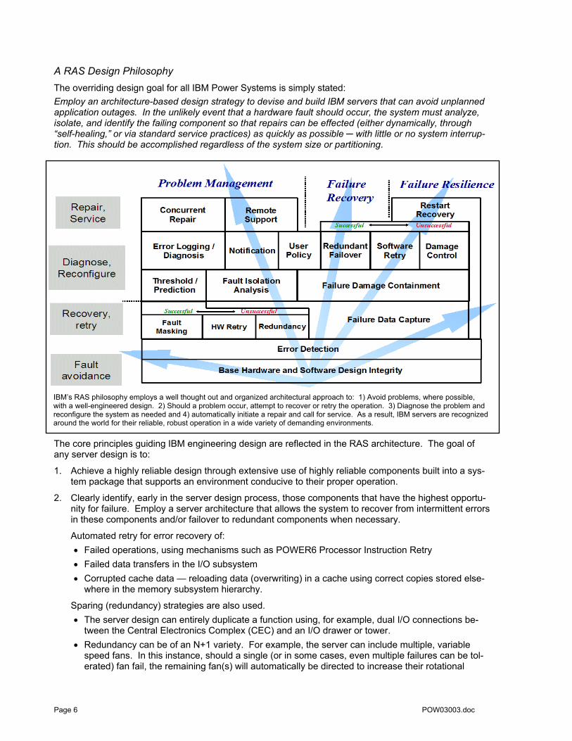
A RAS Design Philosophy The overriding design goal for all IBM Power Systems is simply stated: Employ an architecture-based design strategy to devise and build IBM servers that can avoid unplanned application outages. In the unlikely event that a hardware fault should occur, the system must analyze, isolate, and identify the failing component so that repairs can be effected (either dynamically, through “self-healing,” or via standard service practices) as quickly as possible ─ with little or no system interrup-tion. This should be accomplished regardless of the system size or partitioning.
IBM’s RAS philosophy employs a well thought out and organized architectural approach to: 1) Avoid problems, where possible, with a well-engineered design. 2) Should a problem occur, attempt to recover or retry the operation. 3) Diagnose the problem and reconfigure the system as needed and 4) automatically initiate a repair and call for service. As a result, IBM servers are recognized around the world for their reliable, robust operation in a wide variety of demanding environments.
The core principles guiding IBM engineering design are reflected in the RAS architecture. The goal of any server design is to:
1. Achieve a highly reliable design through extensive use of highly reliable components built into a sys-tem package that supports an environment conducive to their proper operation.
2. Clearly identify, early in the server design process, those components that have the highest opportu-nity for failure. Employ a server architecture that allows the system to recover from intermittent errors in these components and/or failover to redundant components when necessary.
Automated retry for error recovery of: • Failed operations, using mechanisms such as POWER6 Processor Instruction Retry • Failed data transfers in the I/O subsystem • Corrupted cache data — reloading data (overwriting) in a cache using correct copies stored else-
where in the memory subsystem hierarchy.
Sparing (redundancy) strategies are also used. • The server design can entirely duplicate a function using, for example, dual I/O connections be-
tween the Central Electronics Complex (CEC) and an I/O drawer or tower. • Redundancy can be of an N+1 variety. For example, the server can include multiple, variable
speed fans. In this instance, should a single (or in some cases, even multiple failures can be tol-erated) fan fail, the remaining fan(s) will automatically be directed to increase their rotational
Page 6 POW03003.doc

speed, maintaining adequate cooling until a hot-plug repair can be effected. In some cases, even multiple failures can be tolerated.
• Fine grained redundancy schemes can be used at subsystem levels. For example, extra or “spare” bits in a memory system (cache, main store) can be used to effect ECC (Error Checking and Correction) schemes.
IBM engineers draw upon an extensive record of reliability data collected over decades of design and operation of high-end servers. Detailed component failure rate data is used to determine both what redundancy is needed to achieve high levels of system availability, and what level of redundancy pro-vides the most effective balance of reliable operation, server performance, and overall system cost.
When the availability afforded by full redundancy is required, IBM and third party software vendors provide a number of high-availability clustering solutions such as IBM PowerHA™.
3. Develop server hardware that can detect and report on failures and impending failures. • Since 1997, all IBM POWER processor-based servers have employed a design methodology
called First Failure Data Capture (FFDC). This methodology uses hardware-based fault detectors to extensively instrument internal system components [for details, see page 37]. Each detector is a diagnostic probe capable of reporting fault details to a dedicated Service Processor. FFDC, when coupled with automated firmware analysis, is used to quickly and accurately determine the root cause of a fault the first time it occurs, regardless of phase of system operation and without the need to run “recreate” diagnostics. The overriding imperative is to identify which component caused a fault ─ on the first occurrence of the fault ─ and to prevent any reoccurrence of the error.
• One key advantage of the FFDC technique is the ability to predict potentially catastrophic hard-ware errors before they occur. Using FFDC, a Service Processor in a POWER6 or POWER5 processor-based server has extensive knowledge of recoverable errors that occur in a system. Algorithms have been devised to identify patterns of recoverable errors that could lead to an unre-coverable error. In this case, the Service Processor is designed to take proactive actions to guard against the more catastrophic fault (system check-stop or hardware reboot).
4. Create server hardware that is self-healing, that automatically initiates actions to effect error correc-tion, repair, or component replacement. • Striving to meet demanding availabil-
ity goals, POWER6 and POWER5 processor-based systems deploy re-dundant components where they will be most effective. Redundancy can be employed at a functional level (as described above) or at a subsystem level. For example, extra data bit lines in memory can be dynamically activated before a non-recoverable error occurs, or spare bit lines in a cache may be invoked after the fault has occurred.
The goal of self-healing/sparing is to avoid faults by employing sparing where it can most effec-tively prevent an unscheduled outage.
Should a main store memory location experience too many intermittent correctable errors, a POWER5 or POWER6 processor-based server will automatically move the data stored at that location to a “back-up” memory chip. All future references to the original location will auto-matically be accessed from the new chip. Known as “bit-steering”, this is an example of “self-healing.” The system continues to operate with full performance, reliability, and no service call!
• In some instances, even scheduled outages may be avoided by “self-healing” a component. Self-healing concepts can be used to fix faults within a system without having to physically remove or replace a part. IBM’s unique FFDC methodology is used to accurately capture intermittent errors ─ allowing a Service Processor to diagnose potentially faulty components. Using this analysis, a server can “self-heal,” effecting a repair before a system failure actually occurs.
• The unique design characteristics inherent in the FFDC architecture allow POWER6 processor-based servers to capture and isolate potential processor failures when they occur. Then, using saved system state information, a POWER6 processor-based server2 can use Processor Instruc-
Page 7
2 Processor Instruction Retry and Alternate Processor Recovery are available on all POWER6 processor-based servers although Al-ternate Processor Recovery is not available on the BladeCenter® JS12 and JS22
POW03003.doc

POWER5+ MCM • MCM Package
– 4 POWER5+ chips – 4 L3 cache chips
• 3.75” x 3.75” – 95mm x 95mm
• 4,491 signal I/Os
• 89 layers of metal
The POWER5+ multi-chip module design uses proven mainframe packaging technology to pack four POWER5+ chips (eight cores) and four L3 cache chips (36MB each) on a single ceramic sub-strate. This results in a highly reliable, high performance system package for high capacity servers.
tion Retry and Alternate Proces-sor Recovery mechanisms to transparently (to applications) re-cover from errors on the original processor core or on an available spare processor core. In many cases, the server can continue to operate despite fault conditions that were deemed “unrecover-able” in earlier generations of POWER processor-based serv-ers.
• The FFDC methodology is also used to predictively vary-off (deal-locate) components for future scheduled repair. In this case the system will continue to operate, perhaps in a degraded mode, avoiding potentially expensive
unscheduled server outages. One example of this is processor run-time deconfiguration, the abil-ity to dynamically (automatically) take a processor core off-line for scheduled repair before a po-tentially catastrophic system crash occurs.
The POWER6 chip features single- and simultaneous multithreading execution. POWER6 maintains binary compatibility with existing POWER5 processor-based systems to ensure that binaries continue executing properly on the newer systems. Supporting virtualization technologies like its POWER5 predecessor, the POWER6 technology has improved availability and serviceability at both chip and system lev-els. To support the data bandwidth needs of a dual-core processor running at over 3.5 GHz, the POWER6 chip doubles the size of the L1 Data cache (to 64 KB) and includes a 4-fold increase in L2 cache (with 8 MB of on-board cache). Based on a 7-way superscalar design with a 2-way SMT core, the POWER6 microprocessor includes nine (9) instruction execution units. New capabili-ties include specialized hardware for floating-point decimal arithmetic, mem-ory protection keys, and enhanced recovery hardware for processor instruc-tion retry for automatic restart of workloads on the same, or alternate, core in the same server.
• In those rare cases where a fault causes a partition or system outage, FFDC information can be used upon restart to deconfigure (remove from operation) a failing component, allowing the sys-tem or partition to continue operation, perhaps in a degraded mode, while waiting for a scheduled repair.
Reliability: Start with a Solid Base The base reliability of a computing system is, at its most fundamental level, dependent upon the intrinsic failure rates of the components that comprise it. Very simply, highly reliable servers are built with highly reliable components. This basic premise is augmented with a clear “design for reliability” architecture and methodology. Trained IBM RAS engineers use a concentrated, systematic, architecture-based approach designed to improve the overall server reliability with each successive generation of system offerings. At the core of this effort is an intensive focus on sensible, well-managed server design strategies that not only stress high system instruction execution performance, but also require logic circuit implementations that will operate consistently and reliably despite potentially wide disparity in manufacturing process vari-ance and operating environments. Intensive critical circuit path modeling and simulation procedures are used to identify critical system timing dependencies so that time-dependent system operations complete successfully under a wide variety of process tolerances.
During the system definition phase of the server design process, well before any detailed logic design is initiated, the IBM RAS team carefully evaluates system reliability attributes and calculates a server “reliability target.” This target is primarily established by a careful analysis of the potentially attainable reliability (based on available components), and by comparison with current IBM server reliability statistics. In general, RAS targets are set with the goal of exceeding the reliability of currently available servers. For the past decade, IBM RAS engineers have been systematically adding mainframe-inspired RAS technologies to the IBM POWER processor-based server offerings, resulting in dramatically improved system designs.
Page 8 POW03003.doc

In the “big picture” view, servers with fewer components and fewer intercon-nects have fewer chances to fail. Seemingly simple de-sign choices — for example, integrating two processor cores on a single POWER chip — can dramati-cally reduce the “op-portunity” for server failure. In this case, a 64-core server will in-clude half as many processor chips as with a single core per processor design. Not only will this re-duce the total number of system compo-nents, it will reduce the total amount of heat generated in the design, resulting in an additional reduction in required power and cooling components.
The multi-chip model used in an IBM Power 595 server in-cludes a high-performance dual-core POWER6 chip and two L3 Cache modules on a single, highly reliable ceramic sub-strate. Incorporating two L3 cache directories, two memory controllers, and an enhanced fabric bus interface, this mod-ule supports high-performance server configurations.
As indicated by this stylized graphic, four of these modules are mounted on a reliable printed circuit substrate and are connected via both inter-module and in-tra-node system busses. This infra-structure is an extension of, and im-provement on, the fabric bus connec-tions used in the POWER5 p5-595 server configurations. A basic POWER6 595 server uses an 8-core building block (node) that in-cludes up to ½ TB of memory, two Ser-vice Processors, and GX bus controllers for I/O connectivity.
As has been illustrated, system packaging can have a significant impact on server reliability. Since the reliability of electronic components is directly related to their thermal environment – relatively small in-creases in temperature are correlated to large decreases in component reliability –, IBM servers are care-fully packaged to ensure adequate cooling. Critical system components (POWER6 chips for example) are positioned on printed circuit cards so that they receive “upstream” or “fresh” air, while less sensitive or lower power components like memory DIMMs are positioned “downstream.” In addition, POWER6 and POWER5 processor-based servers are built with redundant, variable speed fans that can automatically increase their output to compensate for increased heat in the central electronic complex.
From the smallest to the largest server, system packaging is designed to deliver both high performance and high reliability. In each case, IBM engineers perform an extensive “bottoms-up” reliability analysis us-
ing part level failure rate calculations for every part in the server. These calcula-tions assist the system de-signers when selecting a package that best supports the design for reliability. For example, while the IBM Power 550 and Power 570 servers are similarly pack-aged 19” rack offerings, they employ different proc-essor cards. The more ro-bust Power 570 includes not only additional system fabric connections for perform-ance expansion, but also the robust cooling compo-nents (heat sinks, fans) to compensate for the in-creased heat load of faster
Restructuring the server inter-processor “fabric” bus, the Power 570 and Power 595 support additional interconnection paths between processor building blocks, allowing “point-to-point” connect between every building block. Fabric busses are protected with ECC, enabling the system to correct many data transmission errors. This system topology supports greater system bandwidths and new “ease-of-repair” options.
Maintaining full binary compatibility with IBM’s POWER5 processor, the POWER6 chip offers a number of improvements in-cluding enhanced simultaneous multi-threading, allowing simultaneous, priority-based dispatch from two threads (up to seven instructions) on the same CPU core at the same time (for increased perform-ance), enhanced virtualization features, and improved data movement (reduced cache latencies and faster memory ac-cess). Each POWER6 core includes sup-port for a set of 162 vector-processing in-structions. These floating-point and inte-ger SIMD (Single Instruction, Multiple Data) instructions allow parallel execution of many operations and can be useful in numeric intensive high performance com-puting operations for simulations, model-ing, or numeric analysis.
POW03003.doc Page 9
processors, larger memory, and bigger caches.
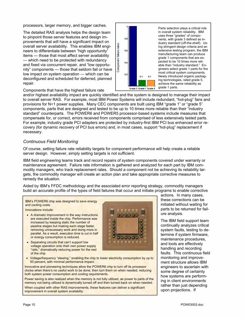
The detailed RAS analysis helps the design team to pinpoint those server features and design im-provements that will have a significant impact on overall server availability. This enables IBM engi-neers to differentiate between “high opportunity” items — those that most affect server availability — which need to be protected with redundancy and fixed via concurrent repair, and “low opportu-nity” components — those that seldom fail or have low impact on system operation — which can be deconfigured and scheduled for deferred, planned repair.
Components that have the highest failure rate and/or highest availability impact are quickly identified and the system is designed to manage their impact to overall server RAS. For example, most IBM Power Systems will include redundant, “hot-plug” fans and provisions for N+1 power supplies. Many CEC components are built using IBM “grade 1” or “grade 5” components, parts that are designed and tested to be up to 10 times more reliable than their “industry standard” counterparts. The POWER6 and POWER5 processor-based systems include measures that compensate for, or correct, errors received from components comprised of less extensively tested parts. For example, industry grade PCI adapters are protected by industry-first IBM PCI bus enhanced error re-covery (for dynamic recovery of PCI bus errors) and, in most cases, support “hot-plug” replacement if necessary.
Continuous Field Monitoring Of course, setting failure rate reliability targets for component performance will help create a reliable server design. However, simply setting targets is not sufficient.
IBM field engineering teams track and record repairs of system components covered under warranty or maintenance agreement. Failure rate information is gathered and analyzed for each part by IBM com-modity managers, who track replacement rates. Should a component not be achieving its reliability tar-gets, the commodity manager will create an action plan and take appropriate corrective measures to remedy the situation.
Aided by IBM’s FFDC methodology and the associated error reporting strategy, commodity managers build an accurate profile of the types of field failures that occur and initiate programs to enable corrective
actions. In many cases, these corrections can be initiated without waiting for parts to be returned for fail-ure analysis.
The IBM field support team continually analyzes critical system faults, testing to de-termine if system firmware, maintenance procedures, and tools are effectively handling and recording faults. This continuous field monitoring and improve-ment structure allows IBM engineers to ascertain with some degree of certainty how systems are perform-ing in client environments rather than just depending upon projections. If When coupled with other RAS improvements, these features can deliver a significant
improvement in overall system availablity.
Innovative and pioneering techniques allow the POWER6 chip to turn off its processor clocks when there’s no useful work to be done, then turn them on when needed, reducing both system power consumption and cooling requirements. Power saving is also realized when the memory is not fully utilized, as power to parts of the memory not being utilized is dynamically turned off and then turned back on when needed.
IBM’s POWER6 chip was designed to save energy and cooling costs. Innovations include: • A dramatic improvement in the way instructions
are executed inside the chip. Performance was increased by keeping static the number of pipeline stages but making each stage faster, removing unnecessary work and doing more in parallel. As a result, execution time is cut in half or energy consumption is reduced.
• Separating circuits that can’t support low voltage operation onto their own power supply “rails,” dramatically reducing power for the rest of the chip.
• Voltage/frequency “slewing,” enabling the chip to lower electricity consumption by up to 50 percent, with minimal performance impact.
Parts selection plays a critical role in overall system reliability. IBM uses three “grades” of compo-nents, with grade 3 defined as in-dustry standard (off-the-shelf). Us-ing stringent design criteria and an extensive testing program, the IBM manufacturing team can produce grade 1 components that are ex-pected to be 10 times more reli-able than “industry standard.” En-gineers select grade 1 parts for the most critical system components. Newly introduced organic packag-ing technologies, rated grade 5, achieve the same reliability as grade 1 parts.
Page 10 POW03003.doc

needed, IBM engineers use this information to undertake “in-flight” corrections, improving current prod-ucts being deployed. This valuable field data is also useful for planning and designing future server prod-ucts.
A System for Measuring and Tracking A system designed with the FFDC methodology includes an extensive array of error checkers and Fault Isolation Registers (FIR) to detect, isolate, and identify faulty conditions in a server. This type of auto-mated error capture and identification is especially useful in allowing quick recovery from unscheduled hardware outages. While this data provides a basis for failure analysis of the component, it can also be used to improve the reliability of the part and as the starting point for design improvements in future sys-tems.
IBM RAS engineers use specially designed logic circuitry to create faults that can be detected and stored in FIR bits, simulating internal chip failures. This technique, called error injection, is used to validate server RAS features and diagnostic functions in a variety of operating conditions (power-on, boot, and operational run-time phases). Error injection is used to confirm both execution of appropriate analysis routines and correct operation of fault isolation procedures that report to upstream applications (the POWER Hypervisor™, operating system, and Service Focal Point and Service Agent applications). Fur-ther, this test method verifies that recovery algorithms are activated and system recovery actions take place. Error reporting paths for client notification, pager calls, and call home to IBM for service are vali-dated and RAS engineers substantiate that correct error and extended error information is recorded. A test servicer, using the maintenance package, then “walks through” repair scenarios associated with sys-tem errors, helping to ensure that all the pieces of the maintenance package work together and that the system can be restored to full functional capacity. In this manner, RAS features and functions, including the maintenance package, are verified for operation to design specifications.
IBM uses the projected client impact of a part failure as the measure of success of the availability design. This metric is defined in terms of application, partition, or system downtime. IBM traditionally classifies hardware error events multiple ways:
1. Repair Actions (RA) are related to the industry standard definition of Mean Time Between Fail-ure (MTBF). A RA is any hardware event that requires service on a system. Repair actions in-clude incidents that effect system availability and incidents that are concurrently repaired.
2. Unscheduled Incident Repair Action (UIRA). A UIRA is a hardware event that causes a sys-tem or partition to be rebooted in full or degraded mode. The system or partition will experience an unscheduled outage. The restart may include some level of capability degradation, but re-maining resources are made available for productive work.
3. High Impact Outage (HIO). A HIO is a hardware failure that triggers a system crash that is not recoverable by immediate reboot. This is usually caused by failure of a component that is critical to system operation and is, in some sense, a measure of system single points-of-failure. HIOs result in the most significant availability impact on the system, since repairs cannot be effected without a service call. A consistent, architecture-driven focus on system RAS (using the techniques described in this document and deploying appropriate configurations for availability), has led to almost complete elimination of High Impact Outages in currently available POWER™ processor-based servers.
The clear design goal for Power Systems is to prevent hardware faults from causing an outage: platform or partition. Part selection for reliability, redundancy, recovery and self-healing techniques, and degraded operational modes are used in a coherent, methodical strategy to avoid HIOs and UIRAs.
Servers Designed for Improved Availability IBM’s extensive system of FFDC error checkers also supports a strategy of Predictive Failure Analysis™: the ability to track “intermittent” correctable errors and to vary components off-line before they reach the point of “hard failure” causing a crash.
This methodology supports IBM’s autonomic computing initiative. The primary RAS design goal of any POWER processor-based server is to prevent unexpected application loss due to unscheduled server hardware outages. In this arena, the ability to self-diagnose and self-correct during run time and to auto-
POW03003.doc Page 11

matically reconfigure to mitigate potential problems from “suspect” hardware, and the ability to “self-heal,” to automatically substitute good components for failing components, are all critical attributes of a quality server design.
System Deallocation of Failing Elements
Persistent Deallocation of Components To enhance system availability, a component that is identified for deallocation or deconfiguration on a POWER6 or POWER5 processor-based server will be flagged for persistent deallocation. Component removal can occur either dynamically (while the system is running) or at boot-time (IPL), depending both on the type of fault and when the fault is detected.
Run-time correctable/recoverable errors are monitored to determine if there is a pattern of errors or a “trend towards uncorrectability.” Should a component reach a predefined error limit, the Service Proces-sor will initiate an action to deconfigure the “faulty” hardware, helping avoid a potential system outage, and enhancing system availability. Error limits are preset by IBM engineers based on historic patterns of component behavior in a variety of operating environments. Error thresholds are typically supported by algorithms that include a time-based count of recoverable errors; that is, the Service Processor responds to a condition of too many errors in a defined time span.
In addition, run-time unrecoverable hardware faults can be deconfigured from the system after the first occurrence. The system can be rebooted immediately after a failure and resume operation on the re-maining good hardware. This prevents the same “faulty” hardware from affecting the system operation again while the repair action is deferred to a more convenient, less critical time for the user operation.
Dynamic Processor Deallocation and Dynamic Processor Sparing First introduced with the IBM RS/6000® S80 server, Dynamic Processor Deallocation allows automatic deconfiguration of an error-prone processor core before it causes an unrecoverable system error (unscheduled server outage). Dynamic Processor Deallocation relies on the Service Processor’s ability to use FFDC generated recoverable-error information and to notify the POWER Hypervisor when the processor core reaches its predefined error limit. The POWER Hypervisor, in conjunction with the operating system (OS), will then “drain” the run-queue for that CPU (core), redistribute the work to the remaining cores, deallocate the offending core, and continue normal operation, although potentially at a lower level of system performance.3
003.doc
Support for dynamic logical partitioning (LPAR) allowed additional system availability improvements. A POWER6 or POWER5 processor-based server that includes an unlicensed core (an unused core included in a “Capacity on Demand (CoD)” system configuration) can be configured for Dynamic Processor Sparing. In this case, as a system option, the unlicensed core can automatically be used to “back-fill” for the deallocated bad processor core. In most cases, this operation is
Should a POWER6 or POWER5 core in a dedicated partition reach a pfined recoverable error threshold, the server can automatically substitspare core before the faulty core crashes. The spare CPU (core) is logically moved to the target system partition; the POWER Hypervisor moves the workload and deallocates the faulty CPU (core) for deferred repair.
rede-ute a
vail-
Capacity on Demand cores will always be selected first by the system for this process. As a second alternative, the POWER Hypervisor will check to see if there is sufficient capacity in the shared processor pool to make a core aable for this operation.
3 While AIX® V4.3.3 precluded the ability for a SMP server to revert to a uniprocessor (i.e., a 2-core to a 1-core configuration), this limitation was lifted with the release of AIX Version 5.2.
Page 12 POW03

transparent to the system administrator and to end users. The spare core is logically moved to the target system partition, the POWER Hypervisor moves the workload, and the failing processor is deallocated. The server continues normal operation with full functionality and full performance. The system generates an error message for inclusion in the error logs calling for deferred maintenance of the faulty component.
The POWER6 and POWER5 processor cores support Micro-Partitioning™ technology, which allows individual cores to run as many as 10 copies of the operating system. This capability allows improvements in the Dynamic Processor Sparing strategy. These cores will support both dedicated processor logical partitions and shared processor dynamic LPARs. In a dedicated processor partition, one or more physical cores are assigned to the partition. In shared processor partitions, a “shared pool” of physical processor cores is defined. This shared processor pool consists of one or more physical processor cores. Up to 10 logical partitions can be defined for every physical processor core in the pool. Thus, a 6-core shared pool can support up to 60 logical partitions. In this environment, partitions are defined to include virtual processor and processor entitlements. Entitlements can be considered performance equivalents; for example, a logical partition can be defined to include 1.7 cores worth of performance.
In dedicated processor partitions, Dynamic Processor Sparing is transparent to the operating system. When a core reaches its error threshold, the Service Processor notifies the POWER Hypervisor to initiate a deallocation event • If a CoD core is available, the POWER Hypervisor automatically substitutes it for the faulty core and
then deallocates the failing core. • If no CoD processor core is available, the POWER Hypervisor checks for excess processor capacity
(capacity available because processor cores are unallocated or unlicensed). The POWER Hypervi-sor substitutes an available processor core for the failing core.
• If there are no available cores for sparing, the operating system is asked to deallocate the core. When the operating system finishes the operation, the POWER Hypervisor stops the failing core.
Dynamic Processor Sparing in shared processor partitions operates in a similar fashion as in dedicated processor parti-tions. In both environments, the POWER Hypervisor is noti-fied by the Service Processor of the error. As previously de-scribed, the system first uses any CoD core(s). Next, the POWER Hypervisor determines if there is at least 1.00 proc-essor units worth of performance capacity available, and if so, stops the failing core, and redistributes the workload.
If the requisite spare capacity is not available, the POWER Hypervisor will determine how many processor core capacity units each partition will need to relinquish to create at least 1.00 processor capacity units. The POWER Hypervisor uses an algorithm based on partition utilization and the defined par-tition minimum and maximums for core equivalents to calcu-late capacity units to be requested from each partition. The POWER Hypervisor will then notify the operating system (via an error entry) that processor units and/or virtual processors need to be varied off-line. Once a full core equivalent is at-tained, the core deallocation event occurs. The deallocation event will not be successful if the POWER Hypervisor and OS cannot create a full core equivalent. This will result in an error message and the requirement for a system administrator to
take corrective action. In all cases, a log entry will be made for each partition that could use the physical core in question.
Dynamic Processor Deallocation from the shared pool uses a similar strategy (but may af-fect up to ten partitions). First, look for avable CoD processor(s). If not available, deter-mine if there is one core’s worth of perforavailable in the pool. If so, rebalance the to allocate the unused resource. If the share
ail-
mance pool
d pool doesn’t have enough avail-ttempt able resource, query the partitions and a
to reduce entitled capacities to obtain the needed performance.
POW03003.doc Page 13

POWER6 Processor Recovery To achieve the highest levels of server avail-ability and integrity, FFDC and recovery safe-guards must protect the validity of user data anywhere in the server, including all the inter-nal storage areas and the buses used to transport data. It is equally important to au-thenticate the correct operation of internal latches (registers), arrays, and logic within a processor core that comprise the system exe-cution elements (branch unit, fixed instruction, floating point instruction unit and so forth) and to take appropriate action when a fault (“er-ror”) is discovered.
The POWER5 microprocessor includes cir-cuitry (FFDC) inside the CPU (processor core) to spot these types of errors. A wide variety of techniques is employed, including built-in pre-cise error check logic to identify faults within controller logic and detect undesirable condi-tions within the server. Using a variety of al-gorithms, POWER5 processor-based servers can recover from many fault conditions; for example, a server can automatically recover from a thread-hang condition. In addition, as discussed in the previous sections, both POWER6 and POWER5 processor-based servers can use Predictive Failure Analysis techniques to vary off (dynamically deallocate) selected hardware components before a fault occurs that could cause an outage (application, partition, or server).
POWER6 cores support Processor Instruction Retry, a method for cor-recting core faults. The recovery unit on each POWER6 core includes more than 2.8 million transistors. More than 91,000 register bits are used to hold system state information to allow accurate recovery from error conditions. Using saved architecture state information, a POWER6 processor can restart and automatically recover from many transient errors. For solid errors, the POWER Hypervisor will attempt to “move” the instruction stream to a substitute core. These tech-niques work for both “dedicated” and “shared pool” cores. A new Partition Availability Priority rating will allow a system atrator to set policy allowing identification of a spare core should a CoD core be unavailable.
dminis-
The POWER6 microprocessor has both incrementally improved the ability of a server to identify potential failure conditions by including enhanced error check logic, and has dramatically improved the capability to recover from core fault conditions. Each core in a POWER6 microprocessor includes an internal process-ing element known as the Recovery Unit (“r” unit). Using the Recovery Unit and associated logic circuits, the POWER6 microprocessor takes a “snap shot,” or “checkpoint,” of the architected core internal state before each instruction is processed by one of the core’s nine-instruction execution units.
Should a fault condition be detected during any cycle, the POWER6 microprocessor will use the saved state information from r unit to effectively “roll back” the internal state of the core to the start of instruction processing, allowing the instruction to be retried from a “known good” architectural state. This procedure is called Processor Instruction Retry. In addition, using the POWER Hypervisor and Service Processor, architectural state information from one recovery unit can be loaded into a different processor core, allow-ing an entire instruction stream to be restarted on a substitute core. This is called Alternate Processor Recovery.
Processor Instruction Retry By combining enhanced error identification information with an integrated Recovery Unit, a POWER6 mi-croprocessor can use Processor Instruction Retry to transparently operate through (recover from) a wider variety of fault conditions (for example “non-predicted” fault conditions undiscovered through predictive failure techniques) than could be handled in earlier POWER processor cores. For transient faults, this mechanism allows the processor core to recover completely from what would otherwise have caused an application, partition, or system outage.
Page 14 POW03003.doc

Alternate Processor Recovery For solid (hard) core faults, retrying the operation on the same processor core will not be effective. For many such cases, the Alternate Processor Recovery feature will deallocate and deconfigure a failing core, moving the instruction stream to, and restarting it on, a spare core. These operations can be ac-complished by the Power Hypervisor and POWER6 processor-based hardware4 without application inter-ruption, allowing processing to continue unimpeded.
• Identifying a Spare Processor Core
Using an algorithm similar to that employed by dynamic processor deallocation (see page 13), the Power Hypervisor manages the process of acquiring a spare processor core. 1. First the POWER Hypervisor checks for spare (unlicensed CoD) processor cores. Should one
not be available, the POWER Hypervisor will look for unused cores (processor cores not as-signed to any partition). When cores are identified, the one with the closest memory affinity to the faulty core is used as a spare.
2. If no spare is available, then the POWER Hypervisor will attempt to “make room” for the instruc-tion thread by over-committing hardware resources or, if necessary, terminating lower priority partitions. Clients manage this process by using an HMC metric, Partition Availability Priority.
• Partition Availability Priority
POWER6 processor-based systems allow administrators to rank order partitions by assigning a nu-meric priority to each partition using service configuration options Partitions receive an integer rat-ing with the lowest priority partition rated at “0” and the highest priority partition valued at “255.” The default value is set at “127” for standard partitions and “192” for VIO server partitions. Partition Availability Priorities are set for both dedicated and shared partitions.
To initiate Alternate Processor Recovery when a spare core is not available, the POWER Hypervisor uses the Partition Availability Priority to determine the best way to maintain unimpeded operation of high priority partitions.
1. Selecting the lowest priority partition(s), the POWER Hypervisor tries to “over-commit” processor core resources, effectively reducing the amount of performance mapped to each virtual processor in the partition. Amassing a “core’s worth” of performance from lower priority partitions, the POWER Hypervisor “frees” a CPU core, allowing recovery of the higher priority workloads. The operating system in an affected partition is notified so that it can adjust the number of virtual processors to best use the currently available performance
2. Since virtual processor performance cannot be reduced below the architectural minimum (0.1 of a core), a low priority partition may have to be terminated to provide needed core computing re-
If Processor Instruction Retry does not scessfully recover from a core error, the POWER Hypervisor will invoke Alternate Processor Recovery, using spare capacity (CoD or unallocated core resources) to move workloads dynamically. This technique can maintain uninterrupted application availability on a POWER6 processor-based server.
uc-
Should a spare core not be available, adminis-trators can manage the impact of Alternate Processor Recovery by establishing a Partition Availability Priority. Set via HMC configuration screens, Partition Availability Priority is a nu-meric ranking (ranging from 0 to 255) for each partition. Using this rating, the POWER Hypervisor takes performance from lower priority parti-tions (reducing their entitled capacity), or if re-quired, stops lower priority partitions so that high priority applications can continue to oper-ate normally.
POW03003.doc Page 15

source. If sufficient resources are still not available to provide a replacement processor core, the next lowest priority partition will be examined and “overcommitted” or terminated. If there are pri-ority “ties” among lower priority partitions, the POWER Hypervisor will select the option that ter-minates the fewest number of partitions.
3. Upon completion of the Alternate Processor Recovery operation, the POWER Hypervisor will de-allocate the faulty core for deferred repair.
Processor Contained Checkstop If a specific processor detected fault cannot be recovered by Processor Instruction Retry and Alternate Processor Recovery is not an option, then the POWER Hypervisor will terminate (checkstop) the partition that was using the processor core when the fault was identified. In general, this limits the outage to a single partition. However, if the failed core was executing a POWER Hypervisor instruction, and the saved state is determined to be invalid, the server will be rebooted. 5
A Test to Verify Automatic Error Recovery5 To validate the effectiveness of the RAS techniques in the POWER6 processor, an IBM engineering team created a test snario to “inject” random errors in the cores.
ce-
over-
em--
heck-
pecula-
Using a proton beam generator, engineers irradiated a POWER6 chip with a proton beam, injecting over 1012 high-energy protons into the chip, at more than 6 orders of magnitude higher flux than would normally be seen by a system in a typical application. The team employed a methodical procedure to correlate an error cage model with measured system response under test. The test team concluded that the POWER6 microprocessor donstrated dramatic improvements in soft-error recovery over previously published results. They reasoned that their success was likely due to key design decisions: 1. Error detection and recovery on data flow logic provides the
ability to recover most errors. ECC, parity, and residue cing are used to protect data paths.
2. Control checking provides fault detection and stops execution prior to modification of critical data. IBM employs both direct and indirect checking on control logic and state machines.
POWER6 Test System mounted in beamline.
As part of the process to verify the coverage model, the latch flip distribution (left) was overlaid on a POWER6 die photo (right).
3. Extensive clock gating prohibits faults injected in non-essential logic blocks from propagating to architected state.
4. Special Uncorrectable Error handling avoids errors on stive paths.
Results showed that the POWER6 microprocessor has industry leading robustness with respect to soft errors in the open systems space.
003.doc
4 This feature is not available on POWER6 blade servers. 5 Jeffrey W. Kellington, Ryan McBeth, Pia Sanda, and Ronald N. Kalla, “IBM POWER6 Processor Soft Error Tolerance Analysis Us-ing Proton Irradiation”, SELSE III (2007).
Page 16 POW03

Protecting Data in Memory Arrays
POWER6 technology A multi-level memory hierarchy is used to stage often-used data “closer” to the cores so that it can be more quickly accessed. While using a memory hierarchy similar to that deployed in earlier generations of servers, the POWER6 processor includes dramatic updates to the internal cache structure to support the increased processor cycle time: • L1 Data (64 KB) and Instruction (64 KB) caches (one each per core) and • a pair of dedicated L2 (4 MB each) caches.
Selected servers include • a 32 MB L3 cache per POWER6 chip. • System (main) memory can range from a maximum of 32 GB on an IBM
BladeCenter JS22 to up to 4 TB on a Power 595 server. As all memory is susceptible to “soft” or intermittent errors, an unprotected mory system would be a significant source of system errors. These servers use avariety of memory protection and correction schemes to avoid or minimize these
em-
problems.
Modern computers offer a wide variety of memory sizes, access speeds, and performance characteristics. System design goals dictate that some optimized mix of memory types be included in any system design so that the server can achieve demanding cost and performance targets.
Powered by IBM’s advanced 64-bit POWER microprocessors, IBM Power Systems are designed to de-liver extraordinary power and reliability, include simultaneous multithreading, which makes each proces-sor core look like two to the operating system, increasing commercial performance and system utilization over servers without simultaneous multithreading capabilities. To support these characteristics, these IBM systems employ a multi-tiered memory hierarchy with L1, L2, and L3 caches, all staging main mem-ory data for the processor core, each generating a different set of memory challenges for the RAS engi-neer.
Memory and cache arrays are comprised of data “bit lines” that feed into a memory word. A memory word is addressed by the system as a single element. Depending on the size and addressability of the memory element, each data bit line may include thousands of individual bits (memory cells). For exam-ple: • A single memory module on a memory DIMM (Dual Inline Memory Module) may have a capacity of
1 Gbits, and supply eight “bit lines” of data for an ECC word. In this case, each bit line in the ECC word holds 128 Mbits behind it (this corresponds to more than 128 million memory cell addresses).
• A 32 KB L1 cache with a 16-byte memory word, on the other hand, would only have 2 Kbits behind each memory bit line.
A memory protection architecture that provides good error resilience for a relatively small L1 cache may be very inadequate for protecting the much larger system main store. Therefore, a variety of different protection schemes is used to avoid uncorrectable errors in memory. Memory protection plans must take into account many factors including size, desired performance, and memory array manufacturing charac-teristics.
One of the simplest memory protection schemes uses parity memory. A parity checking algorithm adds an extra memory bit (or bits) to a memory word. This additional bit holds information about the data that can be used to detect at least a single-bit memory error but usually doesn’t include enough information on the nature of the error to allow correction. In relatively small memory stores (caches for example) that al-low incorrect data to be discarded and replaced with correct data from another source, parity with retry (refresh) on error may be a suf-ficiently reliable methodology.
Error Correction Code (ECC) is an expansion and improvement of parity since the system now includes a number of extra bits in each memory word. The ad-
ECC memory will effectively detect single- and double-bit memory errors. It can automatically fix single-bit errors. A double-bit error (like that shown here), unless handled by other methods, will cause a server crash.
POW03003.doc Page 17

ditional saved information allows the system to detect single- and double-bit errors. In addition, since the bit location of a single-bit error can be identified, the memory subsystem can automatically correct the er-ror (by simply “flipping” the bit from “0” to “1” or vice versa.) This technique provides an in-line mecha-nism for error detection and correction. No “retry” mechanism is required. A memory word protected with ECC can correct single-bit errors without any further degradation in performance. ECC provides ade-quate memory resilience, but may become insufficient for larger memory arrays, such as those found in main system memory. In very large arrays, the possibility of failure is increased by the potential failure of two adjacent memory bits or the failure of an entire memory chip.
IBM engineers designed a memory organization technique that spreads out the bits (bit lines) from a sin-gle memory chip over multiple ECC checkers (ECC words). In the simplest case, the memory subsystem distributes each bit (bit line) from a single memory chip to a separate ECC word. The server can auto-
matically correct even multi-bit errors in a single memory chip. In this scheme, even if an entire memory chip fails, its errors are seen by the memory subsystem as a series of correctable sin-gle-bit errors. This has been aptly named Chipkill™ detec-tion and correction. This means that an entire memory
module can be bad in a memory group, and if there are no other memory errors, the system can run cor-recting single-bit memory errors with no performance degradation.
IBM Chipkill memory can allow a server continue to operate without degradation af-ter even a full memory chip failure.
Transient or soft memory errors (intermittent errors caused by noise or other cosmic effects) that impact a single cell in memory can be corrected by parity with retry or ECC without further problem. Power Sys-tems platforms proactively attempt to remove these faults using a hardware-assisted “memory scrubbing” technique where all the memory is periodically addressed and any address with an ECC error is rewritten with the faulty data corrected. Memory scrubbing is the process of reading the contents of memory through the ECC logic during idle time and checking and correcting any single-bit errors that have accu-mulated. In this way, soft errors are automatically removed from memory, decreasing the chances of en-countering multi-bit memory errors.
IBM Chipkill memory has shown to be more than 100 times more reliable than ECC memory alone. The next challenge in mory design is to handle multiple-bit errors from different memory chips. Dynamic bit-steering resolves many of these errors.
em-
However, even with ECC protection, intermittent or solid failures in a memory area can present a problem if they align with another failure somewhere else in an ECC word. This condition can lead to an uncor-rectable memory error.
Page 18 POW03003.doc

Page 19
To avoid uncorrectable errors in memory, IBM uses a dynamic spare memory scheme called “redundant bit-steering.” IBM main store includes spare memory bits for each ECC word. If a memory bit line is seen to have a solid or intermit-tent fault (as opposed to a tran-sient error) at a substantial number of addresses within a bit line array, the system can move the data stored at this bit line to the spare memory bit line. Systems can automati-cally and dynamically “steer” data to the redundant bit posi-tion as necessary during sys-tem operation.
POWER6 and POWER5 proc-essor-based systems support redundant bit steering for available memory DIMM configurations (consist-ing of x4 DRAMs (four bit lines per DRAM) and x8 DRAMs). The number of sparing events, bits steered per event, and the capability for correction and sparing after a steer event are configuration dependent.
Catastrophic failures at a memory location can result in unrecoverable errors since this bit line will encounter a solid error. Unless this bit position is invalidated (by a technique like dynamic bit-steering), any future solid or intermittent error at the same address will result in a system uncorrectable error and could cause a system crash.
Catastrophic failures • entire row/column • system bit failure • module (chip) failure
• During a bit steer operation, the system continues to run without interruption to normal operations
• If additional correctable errors occur after all steering options have been exhausted, the memory may be called out for a deferred repair during a scheduled maintenance window.
This level of protection guards against the most likely uncorrectable errors within the memory itself:
• An alignment of a bit line failure with a future bit line failure.
• An alignment of a bit line failure with a memory cell failure (transient or otherwise) in another mem-ory module.
Single cell failures receive special handling in POWER6 and POWER5 processor-based servers. While intermittent (soft) failures are corrected using memory scrubbing, the POWER Hypervisor and the operating system manage solid (hard) cell failures. The POWER Hypervisor maintains a list of error pages and works with the operating systems, identifying pages with memory errors for deallocation during normal operation or Dynamic LPAR procedures. The operating system moves stored data from the memory page associated with the failed cell and deletes the page from its memory map. These actions are transparent to end users and applications.
While coincident single cell errors in separate memory chips is a statistic rarity, IBM POWER processor-based servers can contain these errors using a memory page deallocation scheme for partitions running IBM AIX® and the IBM i (for-merly known as i5/OS®) operating systems as well as for memory pages owned by the POWER Hypervisor. If a memory address experiences an uncorrectable or repeated correctable single cell error, the Service Processor sends the memory page address6 to the POWER Hypervisor to be marked for deallocation.
1. Pages used by the POWER Hypervisor are deallocated as soon as the page is re-leased.
2. In other cases, the POWER Hypervisor notifies the owning partition that the page should be deallocated. Where possible, the operating system moves any data cur-rently contained in that memory area to another memory area and removes the
6 Support for 4K and 16K pages only.
POW03003.doc

page(s) associated with this error from its memory map, no longer addressing these pages. The operating system performs memory page deallocation without any user intervention and is trans-parent to end users and applications.
3. The POWER Hypervisor maintains a list of pages marked for deallocation during the current plat-form IPL. During a partition IPL, the partition receives a list of all the bad pages in its address space. In addition, if memory is dynamically added to a partition (through a dynamic LPAR op-eration), the POWER Hypervisor warns the operating system if memory pages are included that need to be deallocated.
Memory page deallocation will not provide additional availability for the unlikely alignment of two simulta-neous single memory cell errors; it will address the subset of errors that can occur when a solid single cell failure precedes a more catastrophic bit line failure or even the rare alignment with a future single mem-ory cell error.
Memory page deallocation handles single cell failures but, because of the sheer size of data in a data bit line, it may be inadequate for dealing with more catastrophic failures. Redundant bit steering will continue to be the preferred method for dealing with these types of problems.
Highly resilient system memory includes multiple memory availability technologies: (1) ECC, (2) memory scrubbing, (3) memory page deallocation, (4) dynamic bit-steering, and (5) Chipkill memory.
Finally, should an uncorrectable error occur, the system can deallocate the memory group associated with the error on all subsequent system reboots until the memory is repaired. This is intended to guard against future uncorrectable errors while waiting for parts replacement.
POWER6 Memory Subsystem While POWER6 processor-based systems maintain the same basic function as POWER5 — including Chipkill detection and correction, a redundant bit steering ca-pability, and OS-based memory page deallocation — the memory subsystem is structured differently.
003.doc
The POWER6 chip includes two memory controllers (each with four ports) and two L3 cache controllers. Delivering exceptional performance for a wide variety of workloads, a Power 595 uses both POWER6 memory controllers and both L3 cache controllers for high mem-ory performance. The other Power models deliver bal-anced performance using only a single memory control-ler. Some models also employ a L3 cache controller.
Supporting large-scale transaction processing and dtabase applications, the Power 595 server uses botmemory controllers and L3 cache controllers built into every POWER6 chip. This organization also delivthe superb memory and L3 cache performaneeded for transparent sharing of processing pobetween partitions, enabling rapid response to chang-ing business requirements.
a-h
ers nce
wer
The memory bus supports ECC checking on data. Ad-dress and command information is ECC protected on models that include POWER6 buffered memory DIMMs. A spare line on the bus is also available for re-pair, supporting IBM’s self-healing strategy.
Page 20 POW03

Page 21
In the Power 570, each port con-nects up to three DIMMS using a daisy-chained bus. Like the other POWER6 processor-based serv-ers, a Power 570 can deconfigure a DIMM that encounters a DRAM fault without deconfiguring the bus controller/buffer chip — even if it is contained on the DIMM.
Uncorrectable Error Handling While it’s a rare occurrence, an uncorrectable data error can oc-cur in memory or a cache despite all precautions built into the server. The goal of POWER6 and POWER5 processor-based systems is to limit, to the least possible disruption, the impact of an uncorrectable error by using a well-defined strategy that begins with considering the data source.
In a Power 570, each of the four ports on a POWER6 memory controller connects up to three DIMMS using a daisy-chained bus. A spare line on the bus is also available for rpair using a self-healing strategy. The meory bus supports ECC checking on data transmissions. Address and command imation is also ECC protected. Using this memory organization, a 16-core Power 570 can deliver up to 786 GB of memory (an atonishing 48 GB per core)!
e-m-
nfor-
s-
Sometimes an uncorrectable error is transient in nature and occurs in data that can be recovered from another repository. For example:
• Data in the POWER5 processor’s Instruction cache is never modified within the cache itself. There-fore, if an uncorrectable error is discovered in the cache, the error is treated like an ordinary cache miss, and correct data is loaded from the L2 cache.
• The POWER6 processor’s L3 cache can hold an unmodified copy of data in a portion of main memory. In this case, an uncorrectable error in the L3 cache would simply trigger a “reload” of a cache line from main memory. This capability is also available in the L2 cache.
For cases where the data cannot be recovered from another source, a technique called Special Uncor-rectable Error (SUE) handling is used.
On these servers, when an uncorrectable error (UE) is identified at one of the many checkers strategically deployed throughout the system’s central electronic complex, the detecting hardware modifies the ECC word associated with the data, creating a special ECC code. This code indicates that an uncorrectable error has been identified at the data source and that the data in the “standard” ECC word is no longer valid. The check hardware also signals the Service Processor and identifies the source of the error. The Service Processor then takes appropriate action to handle the error.
Simply detecting an error does not automatically cause termination of a system or partition. In many cases, a UE will cause generation of a synchronous machine check interrupt. The machine check inter-rupt occurs when a processor tries to load the bad data. The firmware provides a pointer to the instruc-tion that referred to the corrupt data, the system continues to operate normally while the hardware ob-serves the use of the data. The system is designed to mitigate the problem using a number of ap-proaches:
1. If, as may sometimes be the case, the data is never actually used, but is simply over-written, then the error condition can safely be voided and the system will continue to operate normally.
2. For AIX V5.2 or greater or Linux7, If the data is actually referenced for use by a process, then the OS is informed of the error. The OS may terminate, or only terminate a specific process associ-ated with the corrupt data, depending on the OS and firmware level and whether the data was associated with a kernel or non-kernel process.
7 SLES 8 SP3 or later (including SLES 9), and in RHEL 3 U3 or later (including RHEL 4).
POW03003.doc

3. Only in the case where the corrupt data is used by the POWER Hypervisor in a critical area would the entire system be terminated and automatically rebooted, preserving overall system integrity. Critical data is dependant on the system type and the firmware level. For example, on POWER6 processor-based servers, the POWER Hypervisor will in most cases, tolerate partition data uncor-rectable errors without causing system termination.
4. In addition, depending upon system configuration and source of the data, errors encountered dur-ing I/O operations many not result in a machine check. Instead, the incorrect data may be han-dled by the processor host bridge (PHB) chip. When the PHB chip detects a problem, it rejects the data, preventing data being written to the I/O device. The PHB then enters a “freeze” mode halting normal operations. Depending on the model and type of I/O being used, the freeze in-cludes the entire PHB chip, or simply a single bridge. This results in the loss of all I/O operations that use the frozen hardware until a power-on-reset of the PHB occurs. The impact to partition(s) depends on how the I/O is configured for redundancy. In a server configured for “fail-over” avail-ability, redundant adapters spanning multiple PHB chips could enable the system to recover transparently, without partition loss.
Memory Deconfiguration and Sparing Defective memory discovered at IPL time will be switched off by a server.
1. If a memory fault is detected by the Service Processor at boot time, the affected memory will be marked as bad and will not be used on this or subsequent IPLs (Memory Persistent Deallocation).
2. As the manager of system memory, at boot time the POWER Hypervisor decides which memory to make available for server use and which to put in the unlicensed/spare pool, based upon sys-tem performance and availability considerations.
• If the Service Processor identifies faulty memory in a server that includes CoD memory, the POWER Hypervisor attempts to replace the faulty memory with available CoD memory. As faulty resources on POWER6 or POWER5 processor-based offerings are automatically “de-moted” to the system’s unlicensed resource pool, working resources are included in the active memory space.
• On POWER5 mid-range systems (p5-570, i5-570), only memory associated with the first card failure will be spared to available CoD memory. Should simultaneous failures occur on multi-ple memory cards, only the first memory failure found will be spared.
• Since these activities reduce the amount of CoD memory available for future use, repair of the faulty memory should be scheduled as soon as is convenient.
3. Upon reboot, if not enough memory is available; the POWER Hypervisor will reduce the capacity of one or more partitions. The HMC receives notification of the failed component, triggering a service call.
L3 Cache The L3 cache is protected by ECC and Special Uncorrectable Error handling. The L3 cache also incorpo-rates technology to handle memory cell errors.
During system run-time, a correctable error is reported as a recoverable error to the Service Processor. If an individual cache line reaches its’ predictive error threshold, the cache is purged, and the line is dy-namically deleted (removed from further use). The state of L3 cache line delete is maintained in a “deal-location record” so line delete persists through system IPL. This ensures that cache lines “varied offline” by the server will remain offline should the server be rebooted. These “error prone” lines cannot then cause system operational problems. A server can dynamically delete up to 10 cache lines in a POWER5 processor-based server and up to 14 cache lines in POWER6 processor-based models. It is not likely that deletion of this many cache lines will adversely affect server performance. If this total is reached, the L3 cache is marked for persistent deconfiguration on subsequent system reboots until repaired.
Furthermore, for POWER6 processor-based servers, the L3 cache includes a purge delete mechanism for cache errors that cannot be corrected by ECC. For unmodified data, purging the cache and deleting the line ensures that the data is read into a different cache line on reload — thus providing good data to
Page 22 POW03003.doc

the cache, preventing reoccurrence of the error, and avoiding an outage. For a UE on modified data, the data is written to memory and marked as a SUE. Again, purging the cache and deleting the line allows avoidance of another UE, and the SUE is handled using the procedure described on page 21.
Page 23
In addition, POWER6 processor-based servers introduce a hardware-assisted cache memory scrubbing feature where all the L3 cache mem-ory is periodically addressed and any address with an ECC error is rewrit-ten with the faulty data corrected. In this way, soft errors are automatically removed from L3 cache memory, de-creasing the chances of encountering multi-bit memory errors.
In a POWER5 processor-based server, the L1 I-cache, L1 D-cache, L2 cache, L2 directory, and L3 directory all contain additional or “spare” redundant array bits. These bits can be accessed by programmable address logic during stem IPL. Should an array problem be detected, the Array Persistent Dealtion feature will allow the system to automatically “replace” the failing bit positiowith an available spare. In a POWER6 processor-based server, the Processor Instruction Retry and Alternate Processor Recovery features enables quick re-covery from these types of problems.
ys-loca-
n
e-
ami-
In addition, during system run-time, a correctable L3 error is reported as a rcoverable error to the Service Processor. If an individual cache line reaches its predictive error threshold, it will be dynamically deleted. Servers can dyncally delete up to ten (fourteen in POWER6) cache lines. It is not likely that de-letion of a couple of cache lines will adversely affect server performance. This feature has been extended to the L2 cache in POWER6 processors.
Array Recovery and Array Persis-tent Deallocation In POWER5 processor-based serv-
ers, the L1 Instruction cache (I-cache), directory, and instruction effective to real address translation (I-ERAT) are protected by parity. If a parity error is detected, it is reported as a cache miss or ERAT miss. The cache line with parity error is invalidated by hardware and the data is re-fetched from the L2 cache. If the error reoccurs, (the error is solid) or if the cache reaches its soft error limit, the processor core is dy-namically deallocated and an error message for the FRU is generated.
While the L1 Data cache (D-cache) is also parity checked, it gets special consideration when the thresh-old for correctable errors is exceeded. The error is reported as a synchronous machine check interrupt. The error handler for this event is executed in the POWER Hypervisor. If the error is recoverable, the POWER Hypervisor invalidates the cache (clearing the error). If additional soft errors occur, the POWER Hypervisor will disable the failing portion of the L1 D-cache when the system meets its error threshold. The processor core continues to run with degraded performance. A service action error log is created so that when the machine is booted, the failing part can be replaced. The data ERAT and TLB (translation look aside buffer) arrays are handled in a similar manner.
The POWER6 processor’s I-cache and D-cache are protected against transient errors using the Proces-sor Instruction Retry feature and solid failures by Alternate Processor Recovery. In addition, faults in the SLB array are recoverable by the POWER Hypervisor.
In both POWER5 and POWER6 technologies, the L2 cache is protected by ECC. The ECC codes pro-vide single-bit error correction and double-bit error detection. Single-bit errors will be corrected before forwarding to the processor core. Corrected data is written back to L2. Like the other data caches and main memory, uncorrectable errors are handled during run-time by the Special Uncorrectable Error han-dling mechanism. Correctable cache errors are logged and if the error reaches a threshold, a Dynamic Processor Deallocation event is initiated. In POWER6 processor-based models, the L2 cache is further protected by incorporating dynamic cache line delete and purge delete algorithms similar to the features used in the L3 cache (see “L3 Cache” on page 22). Up to six L2 cache lines may be automatically de-leted. It is not likely that deletion of a couple of cache lines will adversely affect server performance. If this total is reached, the L2 is marked for persistent deconfiguration on subsequent system reboots until repair
Array Persistent Deallocation refers to the fault resilience of the arrays in a POWER5 microprocessor. The L1 I-cache, L1 D-cache, L2 cache, L2 directory and L3 directory all contain redundant array bits. If a fault is detected, these arrays can be repaired during IPL by replacing the faulty array bit(s) with the built-in redundancy, in many cases avoiding a part replacement.
POW03003.doc

The initial state of the array “repair data” is stored in the FRU Vital Product Data (VPD) by manufacturing. During the first server IPL, the array “repair data” from the VPD is used for initialization. If an array fault is detected in an array with redundancy by the Array Built-In-Self-Test diagnostic, the faulty array bit is re-placed. Then the updated array “repair data” is stored in the Service Processor persistent storage as part of the “deallocation record” of the processor core. This repair data is used for subsequent system boots.
During system run time, the Service Processor monitors recoverable errors in these arrays. If a prede-fined error threshold for a specific array is reached, the Service Processor tags the error as “pending” in the deallocation record to indicate that the error is repairable by the system during next system IPL. The error is logged as a predictive error, repairable via re-IPL, avoiding a FRU replacement if the repair is successful.
For all processor caches, if “repair on reboot” doesn’t fix the problem, the processor core containing the cache can be deconfigured.
The Input Output Subsystem
A Server Designed for High Bandwidth and Reduced Latency
All IBM POWER6 processor-based servers use a unique “distributed switch” topology providing high bandwidth data busses for fast efficient operation. The high-end Power 595 server uses an 8-core building block. System interconnects scale with proc-essor speed. Intra-MCM and Inter-MCM busses at ½ processor speed. Data movement on the fabric is protected by a full ECC strategy. The GX+ bus is the primary I/O connection path and operates at ½ of the processor speed. In this system topology, every node has a direct connection to every other node, improving bandwidth, reducing latency, and alowing for new availability options when compared to earlier IBM offerings. Offering further improvements that enhance the value of the simultaneous multithreading processor cores, these servers deliver exceptional performance in both transaction processing and numeric-intensive applications. The result is a higher level of SMP scaling. IBM POWER6 processor-based servers can support up to 64 physical processor cores.
l-
Page 24 POW03003.doc

I/O Drawer/Tower Redundant Connections and Concurrent Repair Power System servers support a variety integrated I/O devices (disk drives, PCI cards). The standard server I/O capacity can be significantly expanded in the rack-mounted offerings by attaching optional I/O drawers or I/O towers8 using IBM RIO-G busses9, or on POWER6 processor-based offerings, a 12x channel adapter for optional 12x channel I/O drawers. A remote I/O (RIO) loop or 12x cable loop includes two separate cables providing high-speed attachment. Should an I/O cable become inoperative during normal system operation, the system can automatically reconfigure to use the second cable for all data transmission until a repair can be made. Selected servers also include facilities for I/O drawer or tower concurrent add (while the system continues to operate) and to allow the drawer/tower to be varied on- or off-line. Using these features a failure in an I/O drawer or tower that is configured for availability (I/O de-vices accessed through the drawer must not be defined as “required” for a partition boot or, for IBM i par-titions, ring level or tower level mirroring has been implemented) can be repaired while the main server continues to operate.
GX+ Bus Adapters
A processor book (shown in the diagram and photo on right hand side of drawing) in a POWER6 595 server includes four GX bus slots that can hold GX+ or GX++ adapters for attachment to I/O drawers via RIO or the 12X Channel interface. In some Power System servers, the GX bus can also drive an integrated I/O mul-tifunction bridge.
The GX+ bus provides the primary high band-width path for RIO or GX 12x Dual Channel adapter connection to the system CEC. Errors in a GX+ bus adapter, flagged by system “persis-tent deallocation” logic, cause the adapter to be varied offline upon a server reboot.
GX++ Adapters The GX++ bus, a higher performance version of the GX+ bus, is available on the POWER6 595 (GX++ adapters can deliver over 2 times faster connections to I/O than previous adapters) and the POWER6 520 and 550 systems. While GX++ slots are will support GX+ adapters, GX++ adapters are not compatible with GX+ bus sys-tems. Adapters designed for the GX++ bus pro-vide new levels of error detection and isolation designed to eliminate system check stop condi-tions from all downstream I/O devices, local adapter, and GX++ bus errors, helping to im-prove overall server availability10.
PCI Bus Error Recovery IBM estimates that PCI adapters can account for a significant portion – up to 25% – of the hardware-based error opportunity on a large system. While servers that rely on “boot time” diagnostics can identify failing components to be replaced by “hot-swap” and reconfiguration, run-time errors pose a more signifi-cant problem.
PCI adapters are generally complex designs involving extensive “on-board” instruction processing, often on embedded microcontrollers. Since these are generally cost sensitive designs, they tend to use indus-try standard grade components, avoiding the more expensive (and higher quality) parts used in other parts of the server. As a result, they may encounter internal microcode errors, and/or many of the hard-ware errors described for the entire server.
The traditional means of handling these problems is through adapter internal error reporting and recovery techniques in combination with operating system device driver management and diagnostics. In addition, an error in the adapter may cause transmission of bad data on the PCI bus itself, resulting in a hardware detected parity error (and causing a platform machine check interrupt, eventually requiring a system re-
Page 25
8 I/O towers are available only with IBM i 9 Also referred to as high-speed link (HSL and HSL-2) on IBM i. 10 Requires eFW3.4 or later
POW03003.doc

boot to continue). In 2001, IBM introduced a methodology that uses a combination of sys-tem firmware and new “Ex-tended Error Handling” (EEH) device drivers to allow recov-ery from intermittent PCI bus errors (through recovery/reset of the adapter) and to initiate system recovery for a perma-nent PCI bus error (to include hot-plug replace of the failed adapter).
POWER6 and POWER5 proc-essor-based servers extend the capabilities of the EEH methodology. Generally, all PCI adapters controlled by op-erating system device drivers are connected to a PCI secon-dary bus created through an IBM designed PCI-PCI bridge. This bridge isolates the PCI adapters and supports “hot-plug” by allowing program con-trol of the “power state” of the I/O slot. PCI bus errors related to individual PCI adapters under partition control can be transformed into a PCI slot freeze condition and reported to the EEH device driver for error handling. Errors that occur on the interface between the PCI-PCI bridge chip and the Processor Host Bridge (the link between the proc-essor remote I/O bus and the primary PCI bus) result in a “bridge freeze” condition, effectively stopping all of the PCI adapters attached to the bridge chip. An operating system may recover an adapter from a bridge freeze condition by using POWER Hypervisor functions to remove the bridge from freeze state and resetting or reinitializing the adapters. This same EEH technology will allow system recovery of PCIe bus errors in POWER6 processor-based servers.
Additional Redundancy and Availability
POWER Hypervisor Since the availability of the POWER Hypervisor is crucial to overall system availability, great care has been taken to design high quality, well tested code. In general, a hardware system will see a higher than normal error rate when first introduced and/or when first in-stalled in production. These types of errors are mitigated by strenu-ous engineering and manufacturing verification testing and by using methodologies such as “burn in,” designed to catch the fault before the server is shipped. At this point, hardware failures typically even out at relatively low, but constant, error rates. This phase can last for many years. At some point, however, hardware failures may again increase as parts begin to “wear out.” Clearly, the “design for availability” techniques discussed here will help mitigate these prob-lems.
Coding errors are significantly different from hardware errors. Unlike hardware, code can display a variable rate of failure. New code typically has a higher failure rate and older more seasoned code a very low rate of failure. Code quality will continue to improve as bugs are discovered and fixes installed. Although the POWER
IBM has long built servers with redundant physical I/O paths using CRC checking and failover support to protect RIO server connections from the CEC to the I/O drawers or towers. IBM extended this data protection by introducing first-in-the-industry Extended Error Handling to allow recovery from PCI-bus error conditions. POWER5 and POWER6 processor-based systems add recovery features to handle potential errors in the Processor Host Bridge (PCI bridge), and GX+ adapter (or GX++ bus adapter on POWER6). These features provide improved diagnosis, isola-tion, and management of errors in the server I/O path and new opportunities for con-current maintenance ─ to allow faster recovery from I/O path errors, often without impact to system operation.
Selected multi-node Power Servers (like this p5-570 model) support redundant clocks and Service Processors. The sys-tem allows dynamic failover of Service Processors at run-time and activation of redundant clocks and Service Processors at system boot-time.
Page 26 POW03003.doc

Hypervisor provides important system functions, it is limited in size and complexity when compared to a full operating system implementation, and therefore can be considered better "contained" from a design and quality assurance viewpoint. As with any software development project, the IBM firmware develop-ment team writes code to strict guidelines using well-defined software engineering methods. The overall code architecture is reviewed and approved and each developer schedules a variety of peer code re-views. In addition, all code is strenuously tested, first by “visual” inspections, looking for logic errors, then by simulation and operation in actual test and production servers. Using this structured approach, most coding error are caught and fixed early in the design process.
The POWER Hypervisor is a converged design based on code used in IBM eServer iSeries and pSeries POWER4™ processor-based servers. The development team selected the best firmware design from each platform for inclusion in the POWER Hypervisor. This not only helps reduce coding errors, it also delivers new RAS functions that can improve the availability of the overall server. For example, the pSeries firmware had excellent, proven support for processor error detection and isolation, and included support for Dynamic Processor Deallocation and Sparing. The iSeries firmware had first-rate support for I/O recovery and error isolation and included support for errors like “cable pulls” (handling bad I/O cable connections).
An inherent feature of the POWER Hypervisor is that the majority of the code runs in the protection do-main of a hidden system partition. Failures in this code are limited to this system partition. Supporting a very robust tasking model, the code in the system partition is segmented into critical and non-critical tasks. If a non-critical task fails, the system partition is designed to continue to operate, albeit without the function provided by the failed task. Only in a rare instance of a failure to a critical task in the system par-tition would the entire POWER Hypervisor fail.
The resulting code provides not only advanced features but also superb reliability. It is used in IBM Power Systems and in the IBM TotalStorage® DS8000™ series products. It has therefore been strenu-ously tested under a wide-ranging set of system environments and configurations. This process has de-livered a quality implementation that includes enhanced error isolation and recovery support when com-pared to POWER4 processor-based offerings.
The most powerful member of the IBM Power Systems family, the IBM Power 595 server provides exceptional performance, massive scalability, and energy-efficient processing for complex, mission-critical applications.
Equipped with ultra-high frequency IBM POWER6 processors in up to 64-core, multiprocessing (SMP) configurations, the Power 595 server can scale rapidly and seamlessly to address the changing needs of today’s data center. With advanced PowerVM™ virtualization, EnergyScale™ technology, and Ca-pacity on Demand (CoD) options, the Power 595 helps busi-nesses take control of their IT infrastructure and confidently consolidate multiple UNIX, IBM i (formerly known as i5/OS), and Linux application workloads onto a single system. Extensive mainframe-inspired reliability, availability, and sviceability (RAS) features in the Power 595 help ensure that mission-critical applications run reliably around the clock. The 595 is equipped with a broad range of standard redundancies for improved availability:
er-
– Bulk power & line cords (active redundancy, hot replace) – Voltage regulator modules (active redundancy, hot replace) – Blowers (active redundancy, hot replace) – System and node controllers (SP) (hot failover) – Clock cards (hot failover) – All out of band service interfaces (active redundancy) – System Ethernet hubs (active redundancy) – Vital Product Data and CoD modules (active redundancy) – All LED indicator drive circuitry (active redundancy) – Thermal sensors (active redundancy)
Additional features can support enhanced availability – Concurrent firmware update – I/O drawers with dual internal controllers – Hot add/repair of I/O drawers. – Light strip with redundant, active failover circuitry. – Hot-node Add & Cold- & Concurrent-node Repair* – Hot RIO/GX adapter add
* eFM3.4 or later.
POW03003.doc Page 27

Service Processor and Clocks A number of availability improvements have been included in the Service Processor in the POWER6 and POWER5 processor-based servers. Separate copies of Service Processor microcode and the POWER Hypervisor code are stored in discrete Flash memory storage areas. Code access is CRC protected. The Service Processor performs low-level hardware initialization and configuration of all processors. The POWER Hypervisor performs higher-level configuration for features like the virtualization support required to run up to 254 partitions concurrently on the POWER6 595 and 570, p5-590, p5-595, and i5-595 serv-ers. The POWER Hypervisor enables many advanced functions; including sharing of processor cores, virtual I/O, and high-speed communications between partitions using Virtual LAN. AIX, Linux, and IBM i are supported. The servers also support dynamic firmware updates, in which applications remain opera-tional while IBM system firmware is updated for many operations. Maintaining two copies ensures that the Service Processor can run even if a Flash memory copy becomes corrupted, and allows for redun-dancy in the event of a problem during the upgrade of the firmware.
In addition, if the Service Processor encounters an error during run-time, it can reboot itself while the server system stays up and running. There will be no server application impact for Service Processor transient errors. If the Service Processor encounters a code “hang” condition, the POWER Hypervisor can detect the error and direct the Service Processor to reboot, avoiding other outage.
Two system clocks and two Service Processors are required in all Power 595, i5-595, p5-595 and p5-590 configurations and are optional in 8-core and larger Power 570, p5-570 and i5-570 configurations.
1. The POWER Hypervisor automatically detects and logs errors in the primary Service Processor. If the POWER Hypervisor detects a failed SP or if a failing SP reaches a predefined error thresh-old, the system will initiate a failover from one Service Processor to the backup. Failovers can occur dynamically during run-time.
2. Some errors (such as hangs) can be detected by the secondary SP or the HMC. The detecting unit initiates the SP failover.
Each POWER6 processor chip is designed to receive two oscillator signals (clocks) and may be enabled to switch dynamically from one signal to the other. POWER6 595 servers are equipped with two clock cards. For the POWER6 595, failure of a clock card will result in an automatic (run-time) failover to the secondary clock card. No reboot is required. For other multi-clock offerings, an IPL time failover will oc-cur if a system clock should fail.
003.doc
Node Controller Capability and Redundancy on the POWER6 595 In a POWER6 595 server, the service processor function is spilt between system controllers and node controllers. The system controllers, one ac-tive and one backup, act as supervisors providing a single point of control and performing the bulk of the traditional service processor functions. The node controllers, one active and one backup per node, provide service access to the node-hardware. All the commands from primary sys-tem-controller are routed to both the primary and redundant node-controller. Should a primary note controller fail, the redundant controller will auto-matically take over all node control responsibili-ties.
In this distributed design, the system controller can issue independent commands directly to a specific node controller or broadcast commands to all node controllers. Each individual node con-troller can perform the command, independently, or in parallel with the other node controllers and report results back to the system controller. This
The POWER6 595 server includes a highly redundant service network to facilitate service processor functions and system management. Designed for high availability, components are rdundant and support active failover.
e-
Page 28 POW03

is a more efficient approach than having a single system controller performing a function serially for each node.
System controllers communicate via redundant LANS connecting the power controllers (in the bulk power supplies), the node controllers, and one or two HMCs. This design allows for automatic failover and con-tinuous server operations should any individual component suffer an error.
Hot Node (CEC Enclosure or Processor Book) Add IBM Power 570 systems include the ability11 to add an additional CEC enclosure (node) without powering down the system (Hot-node Add). IBM also provides the capability to add additional processor books (nodes) to POWER6 processor-based 595 systems without powering down the server.12 The additional resources (processors, memory, and I/O) of the newly added node may then be assigned to existing ap-plications or new applications, as required.
For Power 570 servers, at initial system installation clients should install a Service Processor cable that supports the maximum number of drawers planned to be included in the system. The additional Power 595 processor book or Power 570 node is ordered as a system upgrade and added to the original system while operations continue. The additional node resources can then be assigned as required. Firmware upgrades11,12 extends this capability to currently installed POWER6 570 or 595 servers.
Cold-node Repair In selected cases, POWER6 595 or 570 sys-tems that have experienced a failure may be rebooted without activating the failing node (for example, a 12-core 570 system may be re-booted as an 8-core 570 system). This will al-low an IBM Systems Support Representative to repair failing components in the off-line node, and reintegrate the node into the running server without an additional server outage. This capability is provided at no additional charge to current server users via a system firmware update11,12.
Page 29
This feature allows system administrators to set a local policy for server repair and recovery from hardware catastrophic outages.
1. In a multi-node environment, a compo-nent may fail and be deconfigured auto-matically during an immediate server re-boot. Repairing the component may then be scheduled during a maintenance window. In this case, the system would be deactivated; the node containing the failed component would be re-paired, and reintegrated into the system. This policy generally offers server recovery with the smallest impact to overall performance but requires a scheduled outage to complete the repair process.
In the unlikely event that a failure occurs that causes a full server crash, a POWER6 570 can be rebooted with out the failed node on-line. This allows the failed node to be repaired and reinstalled without an additional system outage. This capability can be extended to existing servers via a system firmware update.12
2. As an alternative, the system policy can be set to allow an entire node to be deactivated upon re-boot on failure. The node can be repaired and reintegrated without further outage. Repaired node resources can be assigned to new or existing applications. This policy allows immediate recovery with some loss of capacity (node resources) but avoids a further system outage.
This function, known as “persistent node deallocation” supports a new form of concurrent mainte-nance for system configurations supporting dynamic reintegration of nodes.
11 eFM 3.2.2 and later. 12 eFM 3.4 and later.
POW03003.doc

Concurrent-node Repair13
003.doc
Using predictive failure analysis and dynamic deallocation techniques, an IBM Power Sys-tem delivers the ability to continue to operate, without a system outage, but in a degraded operating condition (i.e., without the use of some of the components).
For selected multi-node server configurations (Power 595, Power 570), a repairer can re-configure a server (move or reallocate work-load), and then deactivate a node. Interact-ing with a graphical user interface, the sys-tem administrator uses firmware utilities to calculate the amount of processor and mem-ory resources that need to be freed up for the service action to complete. The administrator can then use dynamic logical partitioning ca-pabilities to balance partition assets (proces-sor and memory), allocating limited resources to high priority workloads. As connections to I/O devices attached to the node will be lost, care must be taken during initial system configuration to insure that no critical I/O path (without back up) is driven through a single node. In addition, a Power 570 drawer driving system clocks must be repaired via the Cold-node Repair process.
Concurrent-node (processor book) repair allows clients to 1. de-activate 2. repair components or add memory, and then 3. re-activate a POWER6 595 processor book or POWER6 570
node* without powering down. * Note: If the POWER6 570 drawer being repaired is driving the sys-tem clocks, that drawer must be repaired via Cold-node Repair.
Once the node is powered off, the repairer removes and repairs the failed node. Using the Power server hot add capability, the repaired node is dynamically reintegrated into the system. While this process will result in the temporary loss of access to some system capabilities, it allows repair without a full server outage.
For properly configured servers, this capabil-ity supports concurrent:
If sufficient resources are available, the POWER Hypervisor will automatically relocate memory and CPU cycles from a target node to other nodes. In this example, repair of this highly utilized POWER6 595 server can be accomplished using excess system capacity without impact to normal system operations. Once the re-pair is completed, the previous level of over provisioning is restored.
• Processor or memory repair
• Installation of memory, allowing expanded capabilities for capacity and system per-formance
• Repair of an I/O hub (selected GX bus adapters). This function is not supported on a system that has HCA or RIO-SAN configured on any node in the system.
• Node controller (POWER6 595) or Service Processor (POWER6 570) repair.
• Repair of a system backplane or I/O backplane (POWER6 570).
13 eFM 3.4 and later.
Page 30 POW03

Live Partition Mobility Live Partition Mobility, offered as part of IBM PowerVM Enterprise Edition can be of significant value in an
overall availability plan. Live Partition Mobility al-lows clients to move a running partition from one physical POWER6 processor-based server to an-other POWER6 processor-based server without application downtime. Servers using Live Partition Mobility must be managed by either an HMC or In-tegrated Virtualization Manager (IVM). System ad-ministrators can orchestrate POWER6 processor-based servers to work together to help optimize system utilization, improve application availability, balance critical workloads across multiple systems and respond to ever-changing business demands.
Availability in a Partitioned Environment IBM’s dynamic logical partitioning architecture has been extended with Micro-Partitioning technology capabilities. These new features are provided by the POWER Hypervisor and are configured using management interfaces on the HMC. This very powerful approach to partitioning maximizes parti-
If sufficient resource is not avail-able to support all of the currently running partitions, the system identifies potential impacts, allow-ing the client administrator to de-cide how to reallocate available resources based on business needs. In this example, the utility docu-ments limitations in processor cy-cles, memory availability, and posts a variety of warning mes-sages. The system administrator may evaluate each error condition and warning message independently, making informed decisions as to how to reallocate resources to al-low the repair actions to proceed. For instance, selecting the “mem-ory” tab determines how much memory must be made available and identifies partitions using more memory than their minimum re-quirements. Using standard dy-namic logical partitioning tech-niques, memory may be deallo-cated from one or more of these partitions so that the repair action may continue. After each step, the administrator may recheck system repair status, controlling the timing, impact, and nature of the repair.
Using a utility available on the HMC, clients or repairers identify potential application impact prior to initiating the re-pair process. If sufficient capacity is available (memory and processor cycles), the POWER Hypervisor will automatically reallo-cate affected partitions and evacuate a target node.
Live Partition Mobility allows clients to move running partitions from one POWER6 server to another without application down time. Using this feature, system administrators can avoid scheduled outages (for system upgrade or update) by “evacuating” all partitions from an active server to alternate servers. When the update is complete, applications can be moved back — all without impact to active users.
POW03003.doc Page 31

tioning flexibility and maintenance. It supports a consistent partitioning management interface just as ap-plicable to single (full server) partitions as to systems with hundreds of partitions.
In addition to enabling fine-grained resource allocation, these LPAR capabilities provide all the servers in the POWER6 and POWER5 processor-based models the underlying capability to individually assign any resource (processor core, memory segment, I/O slot) to any partition in any combination. Not only does this allow exceptional configuration flexibility, it enables many high availability functions like: • Resource sparing (Dynamic Processor Deallocation and Dynamic Processor Sparing). • Automatic redistribution of capacity on N+1 configurations (automated shared pool redistribution of
partition entitled capacities for Dynamic Processor Sparing). • LPAR configurations with redundant I/O (across separate processor host bridges or even physical
drawers) allowing system designers to build configurations with improved redundancy for automated recovery.
• The ability to reconfigure a server “on the fly.” Since any I/O slot can be assigned to any partition, a system administrator can “vary off” a faulty I/O adapter and “back fill” with another available adapter, without waiting for a spare part to be delivered for service.
• Live Partition Mobility — the ability to move running partitions from one POWER6 processor-based server to another.
• Automated scale-up of high availability backup servers as required (via dynamic LPAR). • Serialized sharing of devices (optical, tape) allowing “limited” use devices to be made available to all
the partitions. • Shared I/O devices through I/O server partitions. A single I/O slot can carry transactions on behalf of
several partitions, potentially reducing the cost of deployment and improving the speed of provision-ing of new partitions (new applications). Multiple I/O server partitions can be deployed for redun-dancy, giving partitions multiple paths to access data and improved availability in case of an adapter or I/O server partition outage.
In a logically partitioning architecture, all of the server memory is physically accessible to all the processor cores and all of the I/O devices in the system, regardless of physical placement of the memory or where the logical partition operates. The POWER Hypervisor mode with Real Memory Offset Facilities enables the POWER Hypervisor to ensure that any code running in a partition (operating systems and firmware) only has access to the physical memory allocated to the dynamic logical partition. POWER6 and POWER5 processor-based systems also have IBM-designed PCI-to-PCI bridges that enable the POWER Hypervisor to restrict DMA (Direct Memory Access) from I/O devices to memory owned by the partition using the device. The single memory cache coherency domain design is a key requirement for delivering the highest levels of SMP performance. Since it is IBM’s strategy to deliver hundreds of dynamically con-figurable logical partitions, allowing improved system utilization and reducing overall computing costs, these servers must be designed to avoid or minimize conditions that would cause a full server outage.
IBM’s availability architecture provides a high level of protection to the individual components making up the memory coherence domain; including the memory, caches, and fabric bus. It also offers advanced techniques designed to help contain failures in the coherency domain to a subset of the server. Through careful design, in many cases failures are contained to a component or to a partition, despite the shared hardware system design. Many of these techniques have been described in this document.
IBM’s approach can be contrasted to alternative designs, which group sub-segments of the server into isolated, relatively inflexible “hard physical partitions.” Hard partitions are generally tied to core and memory board boundaries. Physically partitioning cedes flexibility and utilization for the “promise” of bet-ter availability, since a hardware fault in one partition will not normally cause errors in other partitions. Thus, the user will see a single application outage, not a full system outage. However, if a system uses physical partitioning primarily to eliminate system failures (turning system faults into partition-only faults), then it’s possible to have a very low system crash rate, but a high individual partition crash rate. This will lead to a high application outage rate, despite the physical partitioning approach. Many clients will hesi-tate to deploy “mission-critical” applications in such an environment.
System level availability (in any server, no matter how partitioned) is a function of the reliability of the un-derlying hardware and the techniques used to mitigate the faults that do occur. The availability design of these systems minimizes system failures and localizes potential hardware faults to single partitions in
Page 32 POW03003.doc

multi-partition systems. In this design, while some hardware errors may cause a full system crash (caus-ing loss of all partitions), since the rate of system crashes is very low, the rate of partition crashes is also very low.
The reliability and availability characteristics described in this document show how this “design for avail-ability” approach is consistently applied throughout the system design. IBM believes this is the best ap-proach to achieving partition level availability while supporting a truly flexible and manageable partitioning environment.
In addition, to achieve the highest levels of system availability, IBM, and third-party software vendors offer clustering solutions (e.g., HACMP™) which allow for failover from one system to another, even geo-graphically dispersed systems.
Operating System Availability The focus of this paper is a discussion of RAS attributes in the POWER6 and POWER5 hardware to pro-vide for availability and serviceability of the hardware itself. Operating systems, middleware, and applica-tions provide additional key features concerning their own availability that is outside the scope of this hardware discussion.
It is worthwhile to note, however that hardware and firmware RAS features can provide key enablement for selected software availability features. As can be seen in “Appendix A: Operating System Support for Selected RAS Features” [page 66], many of the RAS features described in this document are applicable to all supported operating systems.
The AIX, IBM i, and Linux operating systems include many reliability features inspired by IBM’s main-frame technology designed for robust operation. In fact, clients in surveys14,15 have selected AIX as the highest quality UNIX operating system. In addition, IBM i offers a highly scalable and virus resistant ar-chitecture with a proven reputation for exceptional business resiliency. IBM i integrates a trusted combi-nation of relational database, security, Web services, networking and storage management capabilities. It provides a broad and highly stable database and middleware foundation — all core middleware compo-nents are developed, tested, and pre-loaded together with the operating system
AIX 6 introduces unprecedented continuous availability features to the UNIX market designed to extend its leadership continuous availability features.
POWER6 servers support a variety of enhanced features:
• POWER6 storage protection keys POWER6 storage protection keys provide hardware-enforced access mechanisms for memory re-gions. Only programs that use the correct key are allowed to read or write to protected memory lo-cations. This new hardware allows programmers to restrict memory access within well-defined, hardware-enforced boundaries, protecting critical portions of AIX 6 and applications software from inadvertent memory overlay.
Storage protection keys can reduce the number of intermittent outages associated with undetected memory overlays inside the AIX kernel. Programmers can also use the POWER6 memory protec-tion key feature to increase the reliability of large, complex applications running under the AIX V5.3 or AIX 6 releases.
• Concurrent AIX kernel update Concurrent AIX updates allow installation of some kernel patches without rebooting the system. This can reduce the number of unplanned outages required to maintain a secure, reliable system.
14 Unix Vendor Preference Survey 4Q’06 – Gabriel Consulting Group Inc. December 2006 15 The Yankee Group “2007-2008 Global Server Operating Systems Reliability Survey” http://www.sunbeltsoftware.com/stu/Yankee-Group-2007-2008-Server-Reliability.pdf
POW03003.doc Page 33

• Dynamic tracing The AIX 6 dynamic tracing facility can simplify debug of complex system or application code. Using a new tracing command, probevue, developers or system administrators can dynamically insert trace breakpoints in existing code without having to recompile — allowing them to more easily trou-bleshoot application and system problems
• Enhanced software First Failure Data Capture AIX V5.3 introduced FFDC technology to gather diagnostic information about an error at the time the problem occurs. Like hardware generated FFDC data, this allows AIX to quickly and efficiently diag-nose, isolate, and in many cases, recover from problems — reducing the need to recreate the prob-lem (and impact performance and availability) simply to generate diagnostic information. AIX 6 ex-tends the FFDC capabilities, introducing more instrumentation to provide real time diagnostic infor-mation.
Availability Configuration Options While many of the availability features discussed in this paper are automatically invoked when needed, proper planning of server configurations can help maximize system availability. Properly configuring I/O devices for redundancy, and creating partition definitions constructed to survive a loss of core or memory resource can improve overall application availability.
An IBM Redbook, "IBM System p5™ Approaches to 24x7 Availability Including AIX 5L16" (SG24-7196) discusses configuring for optimal availability in some detail.
A brief review of some of the most important points for optimizing single system availability: 1. Ensure that all critical I/O adapters and devices are redundant. Where possible, the redundant
components should be attached to different I/O hub controllers. 2. Try to partition servers so that the total number of processor cores defined (as partition minimums)
is at least one fewer then the total number of cores in the system. This allows a core to be deallo-cated dynamically, or on reboot, without partition loss due to insufficient processor core resources.
3. When defining partitions, ensure that the minimum number of required logical memory blocks de-fined for a partition is really the minimum needed run the partition. This will help to assure that suf-ficient memory resources are available after a system boot to allow activation of all partitions — even after a memory deallocation event.
4. Verify that system configuration parameters are set appropriately for the type of partitioning being deployed. Use the "System Configuration" menu of ASMI, determine what resources may be deal-located if a fault is detected. This menu allows clients to set deconfiguration options for a wide va-riety of conditions. For the Power 570 server, this will include setting reboot policy on a node error (reboot with node off-line, reboot with least performance impact).
5. In POWER6 processor-based offerings, use Partition Availability Priority settings to define critical partitions so that the POWER Hypervisor can determine the best reconfiguration method if alternate processor recovery is needed.
6. Do not use dedicated processor partitioning unnecessarily. Shared processor partitioning gives the system the maximum flexibility for processor deallocation when a CoD spare is unavailable.
Serviceability The Service strategy for the IBM POWER6 and POWER5 processor-based servers evolves from, and improves upon, the service architecture deployed on pSeries and iSeries servers. The service team has enhanced the base service capability and continues to implement a strategy that incorporates best-of-breed service characteristics from various IBM eServer systems including the System x®, System i, Sys-tem p, and high-end System z® servers.
16 http://www.redbooks.ibm.com/abstracts/sg247196.html?Open
Page 34 POW03003.doc

The goal of IBM’s Serviceability team is to provide the most efficient service environment by designing a system package that incorporates: • easy access to service components, • on demand service education, • an automated/guided repair strategy using common service interfaces for a converged service ap-
proach across multiple IBM server platforms.
The aim is to deliver faster and more accurate repair while reducing the possibility for human error.
The strategy contributes to higher systems availability with reduced maintenance costs. In many entry-level systems, the server design supports client install and repair of servers and components, allowing maximum client flexibility for managing all aspects of their systems operations. Further, clients can also control firmware maintenance schedules and policies. When taken together, these factors can deliver in-creased value to the end user.
The term “servicer,” when used in the context of this document, denotes the person tasked with perform-ing service related actions on a system. For an item designated as a Customer Replaceable Unit (CRU), the servicer could be the client. In other cases, for Field Replaceable Unit (FRU) items, the servicer may be an IBM representative or an authorized warranty service provider.
Service can be divided into three main categories:
1. Service Components – The basic service related building blocks
2. Service Functions – Service procedures or processes containing one or more service components
3. Service Operating Environment – The specific system operating environment which specifies how service functions are provided by the various service components
The basic component of Service is a Serviceable Event.
Serviceable events are platform, regional, and local error occurrences that require a service action (re-pair). This may include a “call home” to report the problem so that the repair can be assessed by a trained service representative. In all cases, the client is notified of the event. Event notification includes a clear indication of when servicer intervention is required to rectify the problem. The intervention may be a service action that the client can perform or it may require a service provider.
Serviceable events are classified as: 1. Recoverable — this is a correctable resource or function failure. The server remains available, but
there may be some decrease in operational performance available for client’s workload (applications). 2. Unrecoverable —- this is an uncorrectable resource or function failure. In this instance, there is po-
tential degradation in availability and performance, or loss of function to the client’s workload. 3. Predictable (using thresholds in support of Predictive Failure Analysis) —- this is a determination that
continued recovery of a resource or function might lead to degradation of performance or failure of the client’s workload. While the server remains fully available, if the condition is not corrected, an un-recoverable error might occur.
4. Informational — this is notification that a resource or function: a. Is “out-of” or “returned-to” specification and might require user intervention. b. Requires user intervention to complete a system task(s).
Platform errors are faults that affect all partitions in some way. They are detected in the CEC by the Ser-vice Processor, the System Power Control Network, or the Power Hypervisor. When a failure occurs in these components, the POWER Hypervisor notifies each partition’s operating system to execute any re-quired precautionary actions or recovery methods. The OS is required to report these kinds of errors as serviceable events to the Service Focal Point application because, by the definition, they affect the parti-tion in some way. Platform errors are faults related to:
• The Central Electronics Complex (CEC); that part of the server comprised of the central proces-sor units, memory, storage controls, and the I/O Hubs.
• The power and cooling subsystems. • The firmware used to initialize the system and diagnose errors.
POW03003.doc Page 35

Regional errors are faults that affect some, but not all partitions. They are detected by the POWER Hy-pervisor or the Service Processor. Examples of these are RIO bus, RIO bus adapter, PHB, Multi-adapter bridges, I/O Hub, and errors on I/O units (except adapters, devices and their connecting hardware).
Local errors are faults detected in a partition (by the partition firmware or the operating system) for re-sources owned only by that partition. The POWER Hypervisor and Service Processor are not aware of these errors. Local errors may include “secondary effects” that result from platform errors preventing par-titions from accessing partition-owned resources. Examples include PCI adapters or devices assigned to a single partition. If a failure occurs to one of these resources, only a single operating system partition need be informed.
Converged Service Architecture The IBM Power Systems family represents a significant convergence of platform service architectures, merging the best characteristics of the System p, System i, iSeries and pSeries product offerings. This union allows similar maintenance approaches and common service user interfaces. A servicer can be trained on the maintenance of the base hardware platform, service tools, and associated service interface and be proficient in problem determination and repair for POWER6 or POWER5 processor-based plat-form offerings. In some cases, additional training may be required to allow support of I/O drawers, tow-ers, adapters, and devices.
The convergence plan incorporates critical service topics. • Identifying the failing component through architected error codes. • Pinpointing the faulty part for service using location codes and LEDs as part of the guiding light or
lightpath diagnostic strategy. • Ascertaining part numbers for quick and efficient ordering of replacement components. • Collecting system configuration information using common Vital Product Data that completely de-
scribes components in the system, to include detailed information such as their point of manufac-ture and Engineering Change (EC) level.
• Enabling service applications, such as Firmware and Hardware EC Management (described be-low) and Service Agent, to be portable across the multiple hardware and operating system envi-ronments.
The resulting commonality makes possible reduced maintenance costs and lower total cost of ownership for POWER6 and POWER5 processor-based systems. This core architecture provides consistent service interfaces and a common approach to service, enabling owners of selected Power Systems to success-fully perform set-up, manage and carry out maintenance, and install server upgrades; all at their own schedule and without requiring IBM support personnel.
Service Environments The IBM POWER5 and POWER6 processor-based platforms support four main service environments:
1. Servers that do not include a Hardware Management Console. This is the manufacturing default configuration for entry and mid-range systems. Clients may select from two operational environ-ments:
• Stand-alone Full System Partition — the server may be configured with a single partition that owns all the server resources and has only one operating system installed.
• Non-HMC Partitioned System — for selected Power Systems servers, the optional PowerVM feature includes Integrated Virtualization Manager (IVM), a browser-based system interface used to manage servers without an attached HMC. Multiple logical partitions may be created, each with its own operating environment. All I/O is virtualized and shared.
An analogous feature, the Virtual Partition Manager (VPM), is included with IBM i (5.3 and later), and supports the needs of small and medium clients who want to add simple Linux work-loads to their System i5 or Power server. The Virtual Partition Manager (VPM) introduces the capability to create and manage Linux partitions without the use of the Hardware Management Console (HMC). With the Virtual Partition Manager, a server can support one i partition and up
Page 36 POW03003.doc

to four Linux partitions. The Linux partitions must use virtual I/O resources that are owned by the i partition.
2. Server configurations that include attachment to one or multiple HMCs. This is the default con-figuration for high-end systems and servers supporting logical partitions with dedicated I/O. In this case, all servers have at least one logical partition.
The HMC is a dedicated PC that supports configuring and managing servers for either partitioned or full-system partitioned servers. HMC features may be accessed through a Graphical User In-terface (GUI) or a Command Line Interface (CLI). While some system configurations require an HMC, any POWER6 or POWER5 processor-based server may optionally be connected to an HMC. This configuration delivers a variety of additional service benefits as described in the sec-tion discussing HMC-based service.
3. Mixed environments of POWER6 and POWER5 processor-based systems controlled by one or multiple HMCs for POWER6 technologies. This HMC can simultaneously manage POWER6 and POWER5 processor-based systems. An HMC for a POWER5 processor-based server, with a firmware upgrade, can support this environment.
4. The BladeCenter environment consisting of various combinations of POWER processor-based blade servers, x-86 blade servers, Cell Broadband Engine™ processor-based blade servers, and/or storage and expansion blades controlled by the Advanced Management Module (AMM). The management module is a hot-swap device that is used to configure and manage all installed BladeCenter components. It provides system management functions and keyboard/video/mouse (KVM) multiplexing for all the blade servers in the BladeCenter unit. It controls an Ethernet and serial port connections for remote management access.
Service Component Definitions and Capabilities The following section identifies basic service components and defines their capabilities. Service compo-nent usage is determined by the specific operational service environment. In some service environments, higher-level service components may assume a function (role) of a selected service component. Not every service component will be used in every service environment.
Error Checkers, Fault Isolation Registers (FIR), and Who’s on First (WOF) Logic Diagnosing problems in a computer is a critical requirement for autonomic computing. The first step to producing a computer that truly has the ability to “self-heal” is to create a highly accurate way to identify and isolate hardware errors. Error checkers, Fault Isolation Registers, and Who’s on First Logic describe specialized hardware detection circuitry used to detect erroneous hardware operations and to isolate the source of the fault to unique error domain.
All hardware error checkers have distinct attributes. Checkers: 1. Are built to ensure data integrity, continually monitoring system operations. 2. Are used to initiate a wide variety of recovery mechanisms designed to correct the problem.
POWER6 and POWER5 processor-based servers include extensive hardware (ranging from Processor Instruction Retry and bus retry based on parity error detection, to ECC correction on caches and system busses) and firmware recovery logic.
3. Isolate physical faults based on run-time detection of each unique failure.
POW03003.doc Page 37

Error checker signals are captured and stored in hardware Fault Isolation Registers (FIRs). Associated circuitry, called “who’s on first” logic, is used to limit the domain of error checkers to the first checker that encounters the error. In this way, run-time error diagnostics can be deterministic, so that for every check station, the unique error domain for that checker is defined and documented. Ultimately, the error domain becomes the FRU call, and manual interpretation of the data is not normally required.
First Failure Data Capture (FFDC)
IBM has implemented a server design that “builds-in” thousands of hardware error checker stations that capture and help to identify error conditions within the server. A 64-core Power 595 server, for example, includes more than 200,000 checkers to help capture and identify error conditions. These are stored in over 73,000 Fault Isolation Register bits. Each of these checkers is viewed as a “diagnostic probe” into the server, and, when coupled with extensive diagnostic firmware routines, allows quick and accurate as-sessment of hardware error conditions at run-time.
Integrated hardware error detection and fault isolation is a key component of the Power Systems design strategy. It is for this reason that in 1997, IBM introduced First Failure Data Capture (FFDC).
FFDC is a technique that ensures that when a fault is detected in a system (i.e. through error checkers or other types of detection methods), the root cause of the fault will be captured without the need to recreate the problem or run any sort of extended tracing or diagnostics program. For the vast majority of faults, a good FFDC design means that the root cause can also be detected automatically without servicer inter-vention. The pertinent error data related to the fault is captured and saved for analysis. In hardware, FFDC data is collected in fault isolation registers and “who’s on first” logic. In Firmware, this FFDC data is return codes, function calls, etc. FFDC “check stations” are carefully positioned within the server logic and data paths to ensure that potential errors can be quickly identified and accurately tracked to an indi-vidual Field Replaceable Unit (FRU).
This proactive diagnostic strategy is a significant improvement over less accurate “reboot and diagnose” service approaches. Using projections based on IBM internal tracking information, it is possible to predict that high impact outages would occur two to three times more frequently without a FFDC capability. In fact, without some type of pervasive method for problem diagnosis, even simple problems that behave in-termittently can be a cause for serious and prolonged outages.
Fault Isolation Fault isolation is the process whereby the Service Proces-sor interprets the error data captured by the FFDC check-ers (saved in the fault isolation registers and “who’s on first” logic) or other firmware related data capture methods in order to determine the root cause of the error event.
This architecture is also the basis for IBM’s predictive failure analysis, since the Service Processor can now count, and log, intermittent component errors and can deallocate or take other corrective actions when an error threshold is reached.
In this automated approach, run-time error diagnostics can be deterministic, so that for every check station, the unique error domain for that checker is defined and docu-mented. Ultimately, the error domain becomes the FRU (part) call, and manual inter-pretation of the data is not normally required.
First Failure Data Capture, first de-ployed by IBM POWER processor-based servers in 1997, plays a criti-cal role in delivering servers that can self-diagnose and self-heal. Using thousands of checkers (diagnostic probes) deployed at critical junc-tures throughout the server, the sys-tem effectively “traps” hardware er-rors at system run time. The separately powered Service Processor is then used to analyze the checkers and perform problem determination. Using this approach, IBM no longer has to rely on an in-termittent “reboot and retry” error detection strategy, but knows with some certainty which part is having problems.
The root cause of the event may indicate that the event is recoverable (i.e. a service ac-tion point, a need for repair, has not been reached) or that one of several possible condi-tions have been met and the server has arrived at a service action point.
If the event is recoverable, no specific service action may be
Page 38 POW03003.doc

necessary. If the event is deemed a Serviceable Event, additional service information will be required to service the fault. Isolation analysis routines are used to determine an appropriate service action.
• For recoverable faults, threshold counts may simply be incremented, logged, and compared to a service threshold. Appropriate recovery actions will begin if a threshold is exceeded.
• For unrecoverable errors or for recoverable events that meet or exceed their service threshold (a service action point has been reached), a request for service will be initiated through the error logging component.
Error Logging When the root cause of an error has been identified by the fault isolation component, an error log entry is created. The log includes detailed descriptive information. This may include an error code (uniquely de-scribing the error event), the location of the failing component, the part number of the component to be replaced (including the manufacturing pertinent data like engineering and manufacturing levels), return codes, resource identifiers, and some FFDC data. Information describing the effect of the repair on the system may also be included.
Error Log Analysis Error log analysis routines, running on an operating system level, parse a new OS error log entry and:
• Take advantage of the unique perspective afforded the operating system (the OS “sees” all re-sources owned by a partition) to provide a detailed analysis of the entry.
• Maps entries to an appropriate FRU list, based on the machine type and model of the unit en-countering the error.
• Sets logging flags, indicating notification actions such as call home, notify only, and do not raise any alert.
• Formats the entry with flags, message IDs, and control bytes that are needed for message gen-eration, for storage in the problem repository, or by a downstream consumer (like the problem viewer).
The log is placed in selected repositories for problem storage, problem forwarding, or call home. The problem analysis section [Page 39] will describe a variety of methods used to filter these errors.
Problem Analysis Problem analysis is performed in the Service Focal Point application running on the HMC. This applica-tion receives reported service events from all active partitions on a system. The problem analysis appli-cation provides a “system level” view of an event’s root cause. The problem analysis application:
1. Creates a new serviceable event, if one with the same root cause does not already exist. 2. Combines a new serviceable event with an open one that has same root cause. 3. Filters out (deletes) new serviceable events caused by the same service action.
A variety of faults can cause serviceable event points to be reached. Examples include unrecoverable component failures (such as PCI adapters, fans, or power supplies), loss of surveillance or heartbeat be-tween monitored entities (such as redundant Service Processors, or BPC to HMC), or exceeding a threshold for a recoverable event (such as for cache intermittent errors). These events, while “unrecover-able” at a component level (e.g. fan failure, cache intermittent errors) may be recoverable from a server perspective (e.g. redundant fans, dynamic cache line delete).
Analysis of a single event is generally based on error specific data. Analysis of multiple reported events typically employs event-filtering routines that specify grouping types. Events are collated in groups to as-sist in isolating the root cause of the event from all the secondary incidental reported events. The section below, describes the grouping types:
• Time-based (e.g., actual time of the event vs. received time — may be later due to reporting structures)
POW03003.doc Page 39

• Category-based (fatal vs. recoverable) • Subsystem-based (processor vs. disk vs. power, etc.) • Location- based (FRU location) • Trigger-based • Cause and effect-based [or primary events (such as loss of power to I/O drawer) vs. secondary
events (such as I/O timeouts) caused by the primary event or propagated errors] • Client reported vs. Machine reported
The filtering algorithm combines all the serviceable events that result from the same platform —- platform or regional errors. Filtering helps assure that only one call home request is initiated – even if for multiple errors result from the same error event.
Service History Log Serviceable Event(s) data is collected and stored in the Service History Log. Service history includes de-tailed information related to parts replacement and lists serviceable event status (open, closed).
Diagnostics Diagnostics are routines that exercise the hardware and its associated interfaces, checking for proper op-eration. Diagnostics, employed in three distinct phases of system operation: 1. Perform power-up testing for validation of correct system operation at startup (Platform IPL). 2. Monitor the system during normal operation via FFDC strategies. 3. Employ operating system-based routines for error monitoring and handling of conditions not con-
tained in FFDC error domains (e.g., PCI adapters, I/O drawers, or towers).
Platform Initial Program Load
At system power-on, the Service Processor initializes the system hardware. Initial Program Load (IPL) testing employs a multi-tier approach for system validation. Servers include Service Processor managed low-level diagnostics supplemented with system firmware initialization and configuration of I/O hardware, followed by OS-initiated software test routines.
As part of the initialization, the Service Processor can assist in performing a number of different tests on the basic hardware. These include:
1. Built-in-Self-Tests (BIST) for both logic components and arrays. These tests deal with the inter-nal integrity of components. The Service Processor assists in performing tests capable of detect-ing errors within components. These tests can be run for fault determination and isolation, whether or not system processors are operational, and they may find faults not otherwise detect-able by processor-based Power-on-Self-Test (POST) or diagnostics.
2. Wire-Tests discover and precisely identify connection faults between components, for example, between processors and memory or I/O hub chips.
3. Initialization of components. Initializing memory, typically by writing patterns of data and letting the server store valid ECC for each location (and detecting faults through this process), is an ex-ample of this type of operation.
Faulty components detected at this stage can be: 1. Repaired where built-in redundancy allows (e.g., fans, power supplies, spare cache bit lines). 2. Dynamically spared to allow the system to continue booting on an available CoD resource (e.g.,
processor cores, sections of memory). Repair of the faulty core or memory can be scheduled later (deferred).
• If a faulty core is detected, and an available CoD processor core can be accessed by the POWER Hypervisor, then system will “vary on” the spare component using Dynamic Proces-sor Sparing.
• If some physical memory has been marked as bad by the Service Processor, the POWER Hy-pervisor automatically uses available CoD memory at the next server IPL to replace the faulty memory. On some mid-range servers (POWER6 570, p5-570, i5-570), only the first memory card failure can be spared to available CoD memory. On high-end systems, (Power 595,
Page 40 POW03003.doc

POWER5 model 595 or model 590) any amount of failed memory can be spared to available CoD memory.
3. Deallocated to allow the system to continue booting in a degraded mode (e.g., processor cores, sections of memory, I/O adapters).
In all cases, the problem will be logged and reported for repair.
Finally, a set of OS diagnostic routines will be employed during an OS IPL stage to both configure exter-nal devices and to confirm their correct operation. These tests are primarily oriented to I/O devices (disk drives, PCI adapters, I/O drawers or towers).
Run-time Monitoring
All POWER6 and POWER5 processor-based servers include the ability to monitor critical system compo-nents during run-time and to take corrective actions when recoverable faults occur (e.g. power supply and fan status, environmental conditions, logic design). The hardware error check architecture supports the ability to report non-critical errors in an “out-of-band” communications path to the Service Processor, without affecting system performance
The Service Processor includes extensive diagnostic and fault analysis routines developed and improved over many generations of POWER processor-based servers that allow quick and accurate predefined re-sponses to actual and potential system problems.
The Service Processor correlates and processes error information, using error “thresholding” and other techniques to determine when action needs to be taken. Thresholding, as mentioned in previous sec-tions, is the ability to use historical data and engineering expertise to count recoverable errors and accu-rately predict when corrective actions should be initiated by the system. These actions can include: 1. Requests for a part to be replaced. 2. Dynamic (on-line) invocation of built-in redundancy for automatic replacement of a failing part. 3. Dynamic deallocation of failing components so that system availability is maintained.
While many hardware faults are discovered and corrected during system boot time via diagnostics, other (potential) faults can be detected, corrected or recovered during run-time. For example: 1. Disk drive fault tracking can alert the system administrator of an impending disk failure before it af-
fects client operation. 2. Operating system-based logs (where hardware and software failures are recorded) are analyzed by
Error Log Analysis (ELA) routines, which warn the system administrator about the causes of system problems.
Operating System Device Drivers
During operation, the system uses operating system-specific diagnostics to identify and manage prob-lems, primarily with I/O devices. In many cases, the OS device driver works in conjunction with I/O device microcode to isolate and recover from problems. Problems identified by diagnostic routines are reported to an OS device driver, which logs the error.
I/O devices may also include specific “exerciser” routines (that generate a wide variety of dynamic test cases) that can be invoked when needed by the diagnostic applications. Exercisers are a useful element in service procedures that use dynamic fault recreation to aid in problem determination.
Remote Management and Control (RMC) The Remote Management and Control (RMC) application is delivered as part of the base operating sys-tem including the operating system running on the HMC. RMC provides a secure transport mechanism across the LAN interface between the operating system and the HMC. It is used by the operating system diagnostic application for transmitting error information. RMC performs a number of other functions as well, but these are not used for the service infrastructure.
POW03003.doc Page 41

Extended Error Data Extended error data (EED) is either automatically collected at the time of a failure or manually initiated at a later point in time. EED content varies depending on the invocation method, but includes things like the firmware levels, OS levels, additional fault isolation registers, recoverable error threshold registers, sys-tem status, and any information deemed important to problem identification by a component’s developer.
Applications running on the HMC format the EED and prepare it for transmission to the IBM support or-ganization. EED is used by service support personnel to prepare a service action plan to guide the ser-vicer. EED can also provide useful information when additional error analysis is required.
Dumps In some cases, valuable problem determination and service information can be gathered using a system “dump” (for the POWER Hypervisor, memory, or Service Processor). Dumps can be initiated, automati-cally or “on request,” for interrogation by IBM service and support or development personnel. Data col-lected by this operation can be transmitted back to IBM, or in some instances, can be remotely viewed utilizing special support tools if a client authorizes a remote connection to their system for IBM support personnel.
Service Interface The Service Interface allows support personnel to communicate with the service support applications in a server using a console, interface, or terminal. Delivering a clear, concise view of available service appli-cations, the Service Interface allows the support team to manage system resources and service informa-tion in an efficient and effective way. Applications available via the Service Interface are carefully config-ured and placed to give service providers access to important service functions.
Different service interfaces are used depending on the state of the system and its operating environment. The primary service interfaces are:
• LEDs
Guiding light diagnostics use a series of LEDs to lead a servicer directly to a component in need of repair. Using this technology, an IBM SSR or, in some cases, a client can select an error from the HMC. Rack, drawer, and com-ponent LEDs will “blink” to guide the servicer di-rectly to the correct part. This technology can speed accurate and timely repair.
• Operator Panel • Service Processor menu • Operating system service menu • Service Focal Point on the HMC • Service Focal Point Lite on IVM • Service interface on AMM for BladeCenter
LightPath Service Indicator LEDs Lightpath diagnostics use a series of LEDs (Light Emitting Di-odes), quickly guiding a client or Service Support Representa-tive (SSR) to a failed hardware component so that it can be repaired or replaced. When a fault is isolated, the amber ser-vice indicator associated with the component to be replaced is turned on. Additionally, higher level representations of that component are also illuminated up to and including the enclo-sure level indicator. This provides a path that a servicer can follow starting at the system enclosure level, going to an in-termediary operator panel (if one exists for a specific system) and finally down to the specific component or components to be replaced. When the repair is completed, if the error has been corrected, then the service indicator will automatically be turned off to indicate that the repair was successful.
Guiding Light Service Indicator LEDs Guiding light diagnostics are similar in concept to the lightpath diagnostics used in the System x server family to improve problem determination and isolation. Guiding light LEDs support a similar system that is expanded to encompass the service complexities associated with high-end servers. The POWER6 and POWER5 processor-based non-blade models include many RAS features, with capabilities like redun-
Page 42 POW03003.doc

dant power and cooling, redundant PCI adapters and devices, or Capacity on Demand resources utilized for spare service capacity. It is therefore technically feasible to have more than one error condition on a server at any point in time and still have the system be functional from a client and application point of view.
In the guiding light LED implementation, when a fault condition is detected on the POWER5 and POWER6 processor-based product, an amber System Attention LED will be illuminated. Upon arrival at the server, a SSR or service provider sets the identify mode, selecting a specific problem to be identified for repair by the guiding light method. The guiding light system pinpoints the exact part by flashing the amber identify LED associated with the part to be replaced.
The system can not only clearly identify components for replacement by using specific component level indicators, but can also “guide” the servicer directly to the component by signaling (causing to flash) the Rack/Frame System Identify indicator and the Drawer Identify indicator on the drawer containing the component. The flashing identify LEDs direct the servicer to the correct system, the correct enclosure, and the correct component.
In large multi-system configurations, optional row identify beacons can be added to indicate which row of racks contains the system to be repaired. Upon completion of the service event, the servicer resets the Identify LED indicator and the remaining hierarchical identify LEDs are automatically reset. If there are additional faults requiring service, the System Attention LED will still be illuminated and the servicer can choose to set the identify mode and select the next component to be repaired. This provides a consistent unambiguous methodology providing servicers the ability to visually identify the component for repair in the case of multiple faults on the system. At the completion of the service process, the servicer resets the System Attention LED, indicating that all events requiring service have been repaired or acknowledged. Some service action requests may be scheduled for future deferred repair.
Operator Panel The Operator Panel on the IBM POWER5 or POWER6 processor-based systems is a four row by sixteen element LCD display used to present boot progress codes indicating advancement through the system power-on and initialization processes. The Operator Panel is also used to display error and location codes when an error occurs that prevents the system from booting. It includes several push-buttons, al-lowing the SSR or client to select from a menu of boot time options and a limited variety of service func-tions.
The Operator Panel for the BladeCenter is comprised of a front system LED panel. This is coupled with an LED panel on each of the blades for guiding the servicer utilizing the “trail of lights” from the Blade-Center to the individual blade or Power Module and then down to the individual component to be re-placed.
Service Processor The Service Processor is a separately powered microprocessor, separate from the main instruction-processing complex. The Service Processor enables POWER Hypervisor and Hardware Management Console surveillance, selected remote power control, environmental monitoring, reset and boot features, remote maintenance and diagnostic activities, including console mirroring. On systems without a Hard-ware Management Console, the Service Processor can place calls to report surveillance failures with the POWER Hypervisor, critical environmental faults, and critical processing faults even when the main proc-essing unit is inoperable. The Service Processor provides services common to modern computers such as:
1. Environmental monitoring • The Service Processor monitors the server’s built-in temperature sensors, sending instructions
to the system fans to increase rotational speed when the ambient temperature is above the normal operating range.
• Using an architected operating system interface, the Service Processor notifies the operating system of potential environmental related-problems (for example, air conditioning and air cir-culation around the system) so that the system administrator can take appropriate corrective actions before a critical failure threshold is reached.
POW03003.doc Page 43

• The Service Processor can also post a warning and initiate an orderly system shutdown for a variety of other conditions:
– When the operating temperature exceeds the critical level. – When the system fan speed is out of operational specification. – When the server input voltages are out of operational specification.
2. Mutual Surveillance • The Service Processor monitors the operation of the POWER Hypervisor firmware during the
boot process and watches for loss of control during system operation. It also allows the POWER Hypervisor to monitor Service Processor activity. The Service Processor can take appropriate action, including calling for service, when it detects the POWER Hypervisor firm-ware has lost control. Likewise, the POWER Hypervisor can request a Service Processor re-pair action if necessary.
3. Availability • The auto-restart (reboot) option, when enabled, can reboot the system automatically following
an unrecoverable firmware error, firmware hang, hardware failure, or environmentally induced (AC power) failure.
4. Fault Monitoring • BIST (built-in self-test) checks processor, cache, memory, and associated hardware required
for proper booting of the operating system, when the system is powered on at the initial install or after a hardware configuration change (e.g., an upgrade). If a non-critical error is detected or if the error occurs in a resource that can be removed from the system configuration, the booting process is designed to proceed to completion. The errors are logged in the system nonvolatile random access memory (NVRAM). When the operating system completes boot-ing, the information is passed from the NVRAM into the system error log where it is analyzed by error log analysis (ELA) routines. Appropriate actions are taken to report the boot time er-ror for subsequent service if required.
One important Service Processor improvement allows the system administrator or servicer dynamic ac-cess to the Advanced Systems Management Interface (ASMI) menus. In previous generations of servers, these menus were only accessible when the system was in standby power mode. For POWER6, the menus are available from any Web browser-enabled console attached to the Ethernet service network concurrent with normal system operation. A user with the proper access authority and credentials can now dynamically modify service defaults, interrogate Service Processor progress and error logs, set and reset guiding light LEDs, indeed, access all Service Processor functions without having to power-down the system to the standby state.
The Service Processor also manages the interfaces for connecting Uninterruptible Power Source (UPS) systems to the POWER5 and POWER6 processor-based systems, performing Timed Power-On (TPO) sequences, and interfacing with the power and cooling subsystem.
Dedicated Service Tools (DST) The IBM i Dedicated Service Tools (DST) application provides services for Licensed Internal Code (e.g., update, upgrade, install) and disks (format disk, disk copy …), enables resource configuration definition and changes, verifies devices and communication paths, and displays system logs.
DST operates in stand-alone, limited, and full paging environments. The DST tools and functions vary depending on the paging environment and the release level of the operating system.
System Service Tools (SST) On models supporting IBM i, the System Service Tools (SST) application runs one or more Licensed In-ternal Code (LIC) or hardware service functions under the control of the operating system. SST allows the servicer to perform service functions concurrently with the client application programs.
Page 44 POW03003.doc

POWER Hypervisor The advanced virtualization techniques available with POWER technology require a powerful manage-ment interface for allowing a system to be divided into multiple partitions, each running a separate operat-ing system image instance. This is accomplished using firmware known as the POWER Hypervisor. The POWER Hypervisor provides software isolation and security for all partitions.
The POWER Hypervisor is active in all systems, even those containing just a single partition. The POWER Hypervisor helps to enable virtualization technology options including: • Micro-Partitioning technology, allowing creation of highly granular dynamic LPARs or virtual servers
as small as 1/10th of a processor core, in increments as small as 1/100th of a processor core. A fully configured Power 595, Power 575, Power 570, or POWER5 processor-based 595 or 590 can run up to 254 partitions.
• A shared processor pool, providing a pool of processing power that is shared between partitions, helping to improve utilization and throughput.
• Virtual I/O Server, supporting sharing of physical disk storage and network communications adapters, and helping to reduce the number of expensive devices required, improve system utilization, and simplify administration.
• Virtual LAN, enabling high-speed, secure partition-to-partition communications to help improve per-formance.
Elements of the POWER Hypervisor are used to manage the detection and recovery of certain errors, es-pecially those related to the I/O hub (including a GX+ or GX++ bus adapter and the “I/O-planar” circuitry that handles I/O transactions), RIO/HSL and IB Links, and partition boot and termination. The POWER Hypervisor communicates with both the Service Processor, to aggregate errors, and the Hardware Man-agement Console.
The POWER Hypervisor can also reset and reload the Service Processor (SP). It will automatically in-voke a reset/reload of the SP if an error is detected. If the SP does not respond and the reset/reload threshold is reached, the POWER Hypervisor will initiate an orderly shutdown of the system. A downloadable no charge firmware update enables redundant Service Processor failover in properly con-figured Power 595, Power 570, Power 560, i5-595, p5-595, p5-590, i5-570, and p5-570 servers. Once in-stalled, if the error threshold for the failing SP is reached, the system will initiate a failover from one Ser-vice Processor to the backup.
Types of SP errors: • Configuration I/O failure to the SP • Memory-mapped I/O failure to the SP • SP PCI-X/PCI bridge freeze condition
A Service Processor reset/reload is not disruptive and does not affect system operation. SP resets can be initiated by either the POWER Hypervisor or the SP itself. In each case, the system, if necessary, will initiate a smart dump of the SP control store to assist with problem determination if required. Advanced Management Module (AMM) The Advanced Management Module is a hot-swap device that is used to configure and manage all in-stalled BladeCenter components. It provides system management functions and keyboard/video/mouse (KVM) multiplexing for all the blade servers in the BladeCenter unit. It controls an Ethernet and serial port connections for remote management access. All BladeCenter chassis come standard with at least one AMM and support a second AMM for redundancy purposes.
The AMM communicates with all components in the BladeCenter unit and can detect a component’s presence or absence and report on status and send alerts for error conditions when required. A service processor in the AMM communicates with service processors on each of the blades to control power on/off requests and collect error and event reports.
POW03003.doc Page 45

Hardware Management Console (HMC)
The Hardware Management Console is used primarily by the system administrator to manage and con-figure the POWER6 and POWER5 virtualization technologies. The RAS team uses the HMC as an inte-grated service focal point, to con-solidate and report error messages from the system. The Hardware Management Console is also an important component for concur-rent maintenance activities.
003.doc
Key HMC functions include: • Logical partition configuration
and management • Dynamic logical partitioning • Capacity and resource man-
agement • Management of the HMC (e.g.,
microcode updates, access control)
• System status • Service functions (e.g. mi-
crocode updates, “call home” capability, automated service, and Service Focal Point)
• Remote HMC interface • Capacity on Demand options
Service Documentation Service documentation is an im-portant part of a solid serviceability strategy. Clients and service pro-viders rely on accurate, easy to understand and follow, and readily available service documentation to perform appropriate system ser-vice. The variety of service docu-ments are available for use by ser-vice providers, depending on the type of service needed.
• System Installation – Depending on the model
and system complexity, installation can be done either by an IBM System Service Representa-tive or, for Customer Set-Up (CSU) systems, by a client servicer.
The Hardware Management Console is the primary management device for the POWER6/POWER5 virtualization technologies (LPAR, Virtual I/O). It is also used to provide a service focal point to collect and manage all RAS information from the server. Two HMCs may be attached to a server to provide redundancy, if desired. The HMC screen shown below illustrates hardware discovery and mapping capabilities. These features make it easier to understand, and manage, configuration changes and hardware upgrades.
• MES & Machine Type/Model Upgrades – MES changes and/or Machine Type/Model conversions can be performed either by an IBM
System Service Representative or, for those activities that support Customer-installable feature (CIF) or model conversion, by a client servicer.
• System Maintenance procedures can be performed by an IBM System Service Representative or by a client servicer for those activities that support Customer Repair Units (CRU). Maintenance procedures can include: – Problem isolation – Parts replacement procedures – Preventative Maintenance
Page 46 POW03

– Recovery actions
• Problem Determination – Selected procedures, designed to identify the source of error prior to placing a manual call for
service (if automated call home feature is not used), are employed by a client servicer or administrator. These procedures may also be used by the servicer at the outset of the repair action when:
Fault isolation was not precise enough to identify or isolate the failing component. An underlying cause and effect relationship exists. For example, diagnostics may isolate a LAN port fault, but the problem determination routine may conclude that the true problem was caused by a damaged or improperly connected Ethernet cable.
Service documentation is available in a variety of formats, to include softcopy manuals, printouts, graph-ics, interactive media, or videos, and may be accessed via Web-based document repositories, CDs, or from the HMC. Service documents contain step-by-step procedures useful for experienced and inexperi-enced servicers.
System Support Site System Support Site is an electronic information repository that provides on-line training and educational material; allowing service qualification for the various Power Systems offerings.
For POWER6 processor-based servers, service documentation detailing service procedures for faults not handled by the automated Repair and Verify guided component will be available through the System Support Site portal. Clients can subscribe to System Support Site to receive notification of updates to service related documentation as they become available. The latest version of the documentation is ac-cessible through the Internet; however, a CD-ROM based version is also available.
InfoCenter – POWER5 Processor-based Service Procedure Repository IBM Hardware Information Center (InfoCenter) is a repository of client and servicer related product infor-mation for POWER5 processor-based systems. The latest version of the documentation is accessible through the Internet; however, a CD-ROM based version is also available.
The purpose of InfoCenter, in addition to providing client related product information, is to provide soft-copy service procedures to guide the servicer through various error isolation and repair procedures. Be-cause they are electronically maintained, changes due to updates or addition of new capabilities can be used by servicers immediately.
InfoCenter also provides the capability to embed Education-on-Demand modules as reference materials for the servicer. The Education-on-Demand modules encompass information from detailed diagrams to movie clips showing specialized repair scenarios.
Repair and Verify (R&V)
Repair and Verify (R&V) procedures walk the servicer step-by-step through the process of system repair and repair verification. Repair measures include:
• Replacing a defective FRU • Reattaching a lose or disconnected component • Correcting a configuration error • Removing/replacing an incompatible FRU • Updating firmware, device drivers, operating systems, middleware components, and applications
A step-by-step procedure walks the servicer through the process on how to do a repair, in order from be-ginning to end, with only one element requiring servicer intervention per step. Steps are presented in the appropriate sequence for a particular repair and are system specific.
Procedures are structured for use by servicers who are familiar with the repair and for servicers who are unfamiliar with the procedure or a step in the procedure. Education-on-Demand content is placed in the
POW03003.doc Page 47
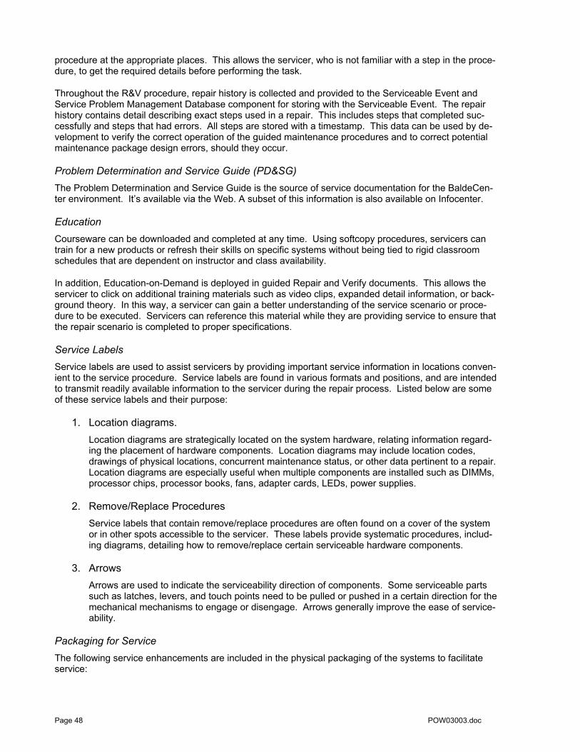
procedure at the appropriate places. This allows the servicer, who is not familiar with a step in the proce-dure, to get the required details before performing the task.
Throughout the R&V procedure, repair history is collected and provided to the Serviceable Event and Service Problem Management Database component for storing with the Serviceable Event. The repair history contains detail describing exact steps used in a repair. This includes steps that completed suc-cessfully and steps that had errors. All steps are stored with a timestamp. This data can be used by de-velopment to verify the correct operation of the guided maintenance procedures and to correct potential maintenance package design errors, should they occur.
Problem Determination and Service Guide (PD&SG) The Problem Determination and Service Guide is the source of service documentation for the BaldeCen-ter environment. It’s available via the Web. A subset of this information is also available on Infocenter.
Education Courseware can be downloaded and completed at any time. Using softcopy procedures, servicers can train for a new products or refresh their skills on specific systems without being tied to rigid classroom schedules that are dependent on instructor and class availability.
In addition, Education-on-Demand is deployed in guided Repair and Verify documents. This allows the servicer to click on additional training materials such as video clips, expanded detail information, or back-ground theory. In this way, a servicer can gain a better understanding of the service scenario or proce-dure to be executed. Servicers can reference this material while they are providing service to ensure that the repair scenario is completed to proper specifications.
Service Labels Service labels are used to assist servicers by providing important service information in locations conven-ient to the service procedure. Service labels are found in various formats and positions, and are intended to transmit readily available information to the servicer during the repair process. Listed below are some of these service labels and their purpose:
1. Location diagrams. Location diagrams are strategically located on the system hardware, relating information regard-ing the placement of hardware components. Location diagrams may include location codes, drawings of physical locations, concurrent maintenance status, or other data pertinent to a repair. Location diagrams are especially useful when multiple components are installed such as DIMMs, processor chips, processor books, fans, adapter cards, LEDs, power supplies.
2. Remove/Replace Procedures Service labels that contain remove/replace procedures are often found on a cover of the system or in other spots accessible to the servicer. These labels provide systematic procedures, includ-ing diagrams, detailing how to remove/replace certain serviceable hardware components.
3. Arrows Arrows are used to indicate the serviceability direction of components. Some serviceable parts such as latches, levers, and touch points need to be pulled or pushed in a certain direction for the mechanical mechanisms to engage or disengage. Arrows generally improve the ease of service-ability.
Packaging for Service The following service enhancements are included in the physical packaging of the systems to facilitate service:
Page 48 POW03003.doc

1. Color Coding (touch points) Terracotta colored touch points indicate that a component (FRU/CRU) can be concurrently main-tained. Blue colored touch points delineate components that are not concurrently maintained —those that require the system to be turned off for removal or repair.
2. Tool-less design Selected IBM systems support tool-less or simple tool designs. These designs require no tools or simple tools such as flat head screw drivers to service the hardware components.
3. Positive Retention Positive retention mechanisms help to assure proper connections between hardware components such as cables to connectors, and between two cards that attach to each other. Without positive retention, hardware components run the risk of becoming loose during shipping or installation, pre-venting a good electrical connection. Positive retention mechanisms like latches, levers, thumb-screws, pop Nylatches® (U-clips), and cables are included to help prevent loose connections and aid in installing (seating) parts correctly. These positive retention items do not require tools.
Blind-swap PCI Adapters “Blind-swap” PCI adapters, first introduced in selected pSeries and iSeries servers in 2001, represent significant service and ease-of-use enhancements in I/O subsystem design. “Standard” PCI designs supporting “hot add” and “hot-replace” require top access so that adapters can be slid to the PCI I/O slots vertically. This approach generally requires an I/O drawer to be slid out of its’ rack and the drawer cover to be removed to provide component access for maintenance. While servers provided features such as cable management systems (cable guides) to prevent inadvertent accidents such as “cable pulls,” this approach required moving an entire drawer of adapters and associated cables to access a single PCI adapter.
Blind-swap adapters mount PCI (PCI, PCI-X, and PCIe) I/O cards in a carrier that can be slid into the rear of a server or I/O drawer. The carrier is designed so that the card is “guided” into place on a set of rails and seated in the slot, completing the electrical connection, by simply shifting an attached lever. This ca-pability allows the PCI adapters to be concurrently replaced without having to put the I/O drawer into a service position. Since first delivered, minor carrier design adjustments have improved an already well-thought out service design. This technology has been incorporated in POWER6 and POWER5 proces-sor-based servers and I/O drawers. In addition, features such as hot add I/O drawers will allow servicers to quickly and easily add additional I/O capacity, rebalance existing capacity, and effect repairs on I/O drawer components.
Vital Product Data (VPD) Server Vital Product Data (VPD) records provide valuable configuration, parts, and component informa-tion that can be used by remote support and service representatives to assist clients in maintaining server firmware and software. VPD records hold system specific configuration information detailing items such amount of installed memory, number of installed processor cores, the manufacturing vintage and service level arts, etc.
Customer Notify Customer notify events are informational items that warrant a client’s attention but do not necessitate im-mediate repair or a call home to IBM. These events identify non-repair conditions, such as configuration errors, that may be important to the client managing the server. A customer notify event may also include a potential fault, identified by a server component, that may not require a repair action without further ex-amination by the client. Examples include a loss of contact over a LAN or an ambient temperature warn-ing. These events may result from faults, or from changes that the client has initiated and is expecting. Customer notify events are, by definition, serviceable events because they indicate that something has happened in a server that requires client notification. The client, after further investigation, may decide to take some action in response to the event. Customer notify events can always be reported back to IBM at the client’s discretion.
POW03003.doc Page 49
Call Home Call home refers to an automated or manual call from a client location to the IBM support organization with error data, server status, or other service-related information. Call home invokes the service organi-zation in order for the appropriate service action to begin. Call home is supported in HMC or non-HMC managed systems. One goal for call home is to have a common look and feel, for user interface and setup, across platforms resulting in improved ease-of-use for a servicer who may be working on groups of systems that span multiple platforms. While configuring call home is optional, clients are encouraged to implement this feature in order to obtain service enhancements such as reduced problem determination, faster and potentially more accurate transmittal of error information. In general, using the call home fea-ture can result in increased system availability.
Inventory Scout The Inventory Scout application can be used to gather hardware VPD and firmware/microcode levels in-formation. This information is then formatted for transmission to IBM. This is done as part of a periodic health check operation to ensure that the system is operational and that the call home path is functional, in case it is required for reporting errors needing service.
IBM Service Problem Management Database System error information can be transmitted electronically from the Service Processor for unrecoverable errors or from Service Agent for recoverable errors that have reached a Service Action Point. Error in-formation can be communicated directly by a client when electronic call home capability is not enabled or for recoverable errors on IVM managed servers. For HMC attached systems, the HMC initiates a call home request when an attached system has experienced a failure that requires service. At the IBM sup-port center, this data is entered into an IBM Service and Support Problem Management database. All of the information related to the error, along with any service actions taken by the servicer are recorded for problem management by the support and development organizations. The problem is then tracked and monitored until the system fault is repaired.
When service calls are placed electronically, product application code on the front end of the problem management database searches for known firmware fixes (and for systems running i, operating system PTFs). If a fix is located, the system will download the updates for installation by the client. In this way, known problems with firmware or i fixes can be automatically sent to the system without the need for re-placing hardware or dispatching a service representative.
Page 50 POW03003.doc

Supporting the Service Environments Because clients may select to operate their servers in a variety of environments [see page 36], service functions use the components described in the last section is a wide range of configurations.
Stand–Alone Full System Partition Mode Environment
Service on non-HMC attached systems begins with Operating System service tools. If an error prevents the OS from booting, the servicer will analyze the Service Processor and Operator Panel error logs. The IBM service application, “System Support Site” or “InfoCenter,” guides the servicer through problem determination and problem resolution proce-dures. When the problem is isolated and repaired, the service application will help the servicer verify correct system op-eration and close the service call. Other types of errors are handled by Service Processor tools and Operator Panel
Stand–Alone Full System Partition Mode Operating Environment Overview
This environment supports a single operating system partition (a “full system” partition) that owns all of the system resources. The primary interface for management and service is the operating system con-sole. Additional management and service capabilities are accessed through the Advanced System Man-agement Interface (ASMI) menus on the Service Processor. ASMI menu functions may be accessed dur-ing with normal system operation via a Web browser-enabled system attached to the service network. ASMI menus are accessed on POWER5 processor-based systems using a service network attached console running a WebSM client.
CEC Platform Diagnostics and Error Handling
In the stand-alone full system partition environment as in the other operating environments, CEC platform errors are detected by the First Failure Data Capture circuitry and error information is stored in the Fault Isolation Registers (FIRs). Processor run-time diagnostics firmware, executing on the Service Processor, analyzes the captured Fault Isolation Register data and determines the root cause of the error, concurrent with normal system operation.
The POWER Hypervisor may also detect certain types of errors within the server’s Central Electronic Complex (CEC). The POWER Hypervisor will detect problems associated with
• Component Vital Product Data (VPD) on I/O units • Capacity Upgrade on Demand (CUoD) • Bus transport chips (I/O hubs, RIO links, IB links, RIO/IB adapters in drawers and the CEC, and
the PCI busses in drawers & CEC) • LPAR boot and crash concerns,
POW03003.doc Page 51

• Service Processor communication errors with the POWER Hypervisor.
The POWER Hypervisor reports all errors to the Service Processor and to the operating system.
The System Power Control Network (SPCN) code, running in the Service Processor and other power con-trol modules, monitors the power and cooling subsystems and reports error events to the Service Proces-sor.
Regardless of which firmware component detects an error, when the error is analyzed, the Service Proc-essor creates a platform event log (PEL log) error entry in the Service Processor error logs. This log con-tains specific related error information including things like system reference codes (which can be trans-lated into a natural language error messages), location codes (indicating the logical location of the com-ponent within the system), and other pertinent information related to the specific error (such as whether the error was recoverable, fatal, predictive). In addition to logging the event, the failure information is sent to the Operator Panel for display.
If the error did not originate in the POWER Hypervisor, then the PEL log is transferred from the Service Processor to the POWER Hypervisor, which then transfers the error to the operating system logs.
While there are some minor differences between the various operating system components, they all gen-erally follow a similar process for handling errors passed to them from the POWER Hypervisor.
• First, the PEL is stored in the operating system log. Then, the operating system performs addi-tional system level analysis of the error event.
• At this point, OS service applications may perform additional problem analysis to combine multiple reported events into a single event.
• Finally, the operating system components convert the PEL from the Service Processor into a Ser-vice Action Event Log (SAEL). This report includes additional information on whether the service-able event should only be sent to the system operator or whether it should also be marked as a call home event. If the call home electronic Service Agent application is configured and opera-tional, then the Service Agent application will place the call home to IBM for service.
I/O Device and Adapter Diagnostics and Error Handling
For faults that occur within I/O adapters or devices, the operating system device driver will often work in conjunction with I/O device microcode to isolate and recover from these events. Potential problems are reported to an OS device driver, which logs the error in the operating system error log. At this point, these faults are handled in the same fashion as other operating system platform-logged events. Faults are recorded in the service action event log; notification is sent to the system administrator and may be forwarded to the Service Agent application to be called home to IBM for service. The error is also dis-played on the Operator Panel on the physical system.
Some rare circumstances require the invocation of concurrent or stand-alone (user-initiated) diagnostic exercisers to attempt to recreate an I/O adapter or device related error or exercise related hardware. For instance, specialized routines may be used to assist with diagnosing cable interface problems, where wrap plugs or terminators may be needed to aid with problem identification. In these cases, the diagnos-tic exercisers may be run concurrently with system operation if the associated hardware can be freed from normal system operation, or the diagnostics may be required to run in stand-alone mode with no other client level applications running.
Service Documentation
All service related documentation resides in one of two repositories. For POWER5 processor-based sys-tems, all service related information is in InfoCenter. For POWER6 processor-based systems, the reposi-tory is System Support Site. These can be also be accessed from the internet or from a DVD.
For systems with IBM service, customized installation and MES instructions are provided for installing the system or for adding or removing features. These customized instructions can also be accessed through the Internet to obtain the latest procedures.
For systems with customer service, installation and MES instructions are provided through InfoCenter (POWER5 processor-based systems) or through System Support Site (POWER6 processor-based sys-tem). The latest version of these instructions can also be obtained from the Internet.
Page 52 POW03003.doc

LED Management When an error is discovered, the detecting entity (Service Processor, System Power Control Network code, POWER Hypervisor, operating system) sets the system attention LED (solid amber LED on the front of the system). When a servicer is ready to begin system repair, as directed by the IBM support center or the mainte-nance package, the specific component to be repaired is selected via an operating system or SP service menu. This action places the service component LED in the identify mode, causing a trail of amber LEDs to blink. The first to blink is the system identify LED, followed by the specific enclosure (drawer, tower, etc) LED where the component is housed, and the identify LED associated with the serviceable compo-nent. These lights guide the servicer to the system, enclosure, and component requiring service.
LED operation is controlled is through the operating system service menus. If the OS is not available, LEDs may be managed using Service Processor menus. These menus can be used to control the CEC platform and power and cooling component related LEDs.
Service Interface
Service on non-IVM, non-HMC attached systems begins with the operating system service tools. If an er-ror prevents the operating system from booting, the servicer analyzes the Service Processor and Opera-tor Panel error logs. Service documentation and procedures guide the servicer through problem determi-nation and problem resolution steps. When the problem is isolated and repaired, the servicer verifies cor-rect system operation and closes the service call.
Dumps
Any dumps that occur because of errors are loaded to the operating system on a reboot. If the system is enabled for call home, depending on the size and type of dump key information from the dump or the dump in its entirety will be transmitted to an IBM support repository for analysis. If the dump is too large to transmit, then it can be offloaded and sent through other means to the back-end repository.
Call Home
Service Agent is the primary call home application running on the operating system. If the operating system is operational, even if it crashed and rebooted, Service Agent reports all system errors to IBM service for repair.
In the unlikely event that an unrecoverable checkstop error occurs, preventing operating system recovery, errors will be reported to IBM by the Service Processor call home feature.
It is important in the Stand-Alone Full system partition environment to enable and configure the call home application in both the Service Processor and the Service Agent application for full error reporting and automatic call forwarding to IBM.
Inventory Management
All hardware Vital Product Data (VPD) is collected during the IPL process and passed to the operating system as part of the device tree. The operating system then maintains a copy of this data.
Inventory data is included in the extended error data when an error is called home to IBM support or dur-ing a periodic Inventory Scout health check operation. The IBM support organization maintains a sepa-rate data repository for VPD information that is readily available for problem analysis.
Remote support
If necessary, and when authorized by the client, IBM can establish a remote terminal session with the Service Processor so that trained product experts can analyze extended error log information or attempt remote recovery or control of a server.
POW03003.doc Page 53

Operator Panel
Servers configured with a stand-alone full system partition include a hardware-based Operator Panel used to display boot progress indicators during the boot process and failure information on the occur-rence of a serviceable event.
Firmware Upgrades
Firmware can be upgraded through one of several different mechanisms that required a scheduled out-age in a system in the stand-alone full system partition-operating environment. Upgraded firmware im-ages can be obtained from any of several sources:
1. IBM distributed media (such as CD-ROM) 2. A Problem Fix distribution from the IBM Service and Support repository 3. Download from the IBM Web site (http://www14.software.ibm.com/webapp/set2/firmware) 4. FTP from another server
Once the firmware image is obtained in the operating system, a command is invoked either from the command line or from the operating system service application to begin the update process. First, the firmware image in the temporary side of Service Processor Flash is copied to the permanent side of flash. Then, the new firmware image is loaded from the operating system into the temporary side of Service Processor Flash and the system is rebooted. On the reboot, the upgraded code on the temporary side of the Service Processor flash is used to boot the system.
If for any reason, it becomes necessary to revert to the prior firmware level, then the system can be booted from the permanent side of flash that contains the code level that was active prior to the firmware upgrades.
Integrated Virtualization Manager (IVM) Partitioned Operating Environment
The SFP-Lite application, running on the IVM partition, is the repository for Serviceable Events and for system and Ser-vice Processor dumps. Service on IVM controlled systems begins with the Service Focal Point Lite service application. SFP-Lite uses service problem isolation and service procedures found in the service procedures service repository when maintenance is required. Once a problem is isolated and repaired, service procedures help the servicer verify correct system operation and close the service call. For some selected errors, service procedures are augmented by Service Processor tools and Operator Panel Messages.
Page 54 POW03003.doc

Integrated Virtualization Manager (IVM) Operating Environment Overview
Integrated Virtualization Manager is an interface used to create logical partitions, manage virtual storage and virtual Ethernet, and view server service information. Servers using IVM do not require an HMC, al-lowing cost-effective consolidation of multiple partitions in a single server.
The IVM supports: • Creating and managing logical partitions • Configuring virtual Ethernet networks • Managing storage in the VIOS • Creating and managing user accounts • Creating and managing serviceable events through the Service Focal Point Lite • Downloading and installing updates to device microcode and to the VIOS software • Backing up and restoring logical partition configuration information • Viewing application logs and the device inventory
In an IVM managed server, the Virtual I/O Server (VIOS) partition owns all of the physical I/O resources and a portion of the memory and processor resources. Using a communication channel through the Ser-vice Processor, the IVM directs the POWER Hypervisor to create client partitions by assigning processor and memory resources.
The IVM provides a subset of HMC service functions. The IVM is the repository for Serviceable Events and for system and Service Processor dumps. It allows backup, restore of partition and VIOS configura-tions, and manages system firmware and device microcode updates. For those clients requiring ad-vanced features such as concurrent firmware maintenance or remote support for serviceable events, IBM recommends the use of the Hardware Management Console.
Because the IVM is running within a partition, some management functions, such as system power on and off, are controlled through the ASMI menus.
Virtual Partition Manager
IBM i includes support for virtual partition management to enable the creation and management of Linux partitions without the requirement for a Hardware Management Console (HMC).
The Virtual Partition Manager17 (VPM) supports the needs of small and medium clients who want to add simple Linux workloads to their Power server or System i5. Virtual Partition Manager is enabled by the partition management tasks in the Dedicated Service Tools (DST) and System Service Tools (SST).
With the Virtual Partition Manager, a System i5 can support one i partition and up to four Linux partitions. The Linux partitions must use virtual I/O resources that are owned by the i partition. VPM support is in-cluded with i5/OS V5R3 and i 5.4 (formerly V5R4) for no additional charge. Linux partition creation and management is performed through DST or SST tasks. VPM supports a sub-set of service functions supported on a HMC managed server. • The i PTF process is used for adapter microcode and system firmware updates. • I/O concurrent maintenance is provided through i support for device, slot, and tower concurrent main-
tenance. • Serviceability event management is provided through i support for firmware and management parti-
tion detected errors, • POWER Hypervisor and Service Processor dump support is available through i dump collection and
call home. • Remote support is available through i (no firmware remote support).
17 Details can be found in the IBM Redpaper “Virtual Partition Manager a Guide to Planning and Implementation.” http://www.redbooks.ibm.com/redpapers/pdfs/redp4013.pdf
POW03003.doc Page 55

Service Documentation
Documentation in the IVM environment is the same as described in the Stand-Alone Full System Partition operating environment described on page 52.
CEC Platform Diagnostics and Error Handling
CEC platform-based diagnostics in the IVM environment use the same methods as those in a Stand-Alone Full system partition mode of operation and support the same capabilities and functions [page 51].
Additionally, the POWER Hypervisor forwards the PEL log from the Service Processor to the operating system in every active partition. Each operating system handles the platform error appropriately based on their respective policies.
I/O Device and Adapter Diagnostics and Error Handling
The IVM partition owns all I/O resources and, through the virtualization architecture, makes them acces-sible to operating system partitions. Because the VIOS partition owns the physical I/O devices and adapters, it detects, logs and reports errors associated with these components. The VIOS partitions uses the device drivers and microcode recovery techniques previously described for OS device drivers [page 52]. Faults are logged in the VIOS partition error log and forwarded to the SFP-Lite service application running on the same partition. SFP-Lite provides error logging and problem management capabilities for errors reported through the IVM partition.
Service Focal Point Lite (SFP-Lite) Error Handling
The SFP-Lite service application running on the IVM partition provides a subset of the service functions provided in the HMC-based Service Focal Point (SFP) service application. The SFP-Lite application is the repository for Serviceable Events and for system and Service Processor dumps. The IVM partition is notified of CEC platform events. It also owns all I/O devices and adapters and maintains error logs for all I/O errors. Therefore, error reporting is not required from other partitions; the IVM partition log holds a complete listing of all system serviceable events. The SFP-Lite application need not perform error log fil-tering for duplicate events before it directs maintenance actions.
LED Management
In the IVM operating environment, the system attention LED is controlled through the SFP-Lite applica-tion. Identify service LEDs for the CEC and I/O devices and adapters are managed through service con-trol menus in the IVM partition. If the IVM partition cannot be booted, the LEDs are controlled through the ASMI menus.
Service Interface
Service on IVM controlled systems begins with the Service Focal Point-Lite service application. SFP-Lite uses service problem isolation and service procedures found in the InfoCenter service repository when maintenance is required. Once a problem is isolated and repaired, InfoCenter tools help the servicer ver-ify correct system operation and close the service call. If a rare critical error prevents IVM partition boot, InfoCenter procedures are augmented by Service Processor tools and Operator Panel Messages
Dumps
Error-initiated dump data is forwarded to the IVM operating system during reboot. This data can be off-loaded and sent a back-end repository at IBM for analysis.
Call Home
In the IVM operating environment, critical unrecoverable errors will be forwarded to a service organization from a Service Processor that is properly configured and enabled for call home.
Page 56 POW03003.doc

Inventory Management
Hardware VPD is gathered and reported to the operating systems as previously explained in the stand-alone full system partition section on page 53. The Inventory Scout application is not used in the IVM en-vironment.
Remote Support
If necessary, and when authorized by the client, IBM can establish a remote terminal session with the Service Processor so that trained product experts can analyze extended error log information or attempt remote recovery or control of a server.
Operator Panel
The Operator Panel displays boot progress indicators until the POWER Hypervisor achieves “standby” state, immediately prior to OS boot. If needed, it also shows information about base CEC platform errors.
Using the SFP-Lite application a client may open a virtual Operator Panel interface to the other partitions running on the system. This virtual Operator Panel supports a variety of capabilities. Examples include displaying partition boot-progress indicators and partition-specific error information.
Firmware Upgrades
Firmware upgrades in the IVM operating environment are performed the same as explained in the stand alone full system partitioned mode on page 54.
Hardware Management Console (HMC) Attached Partitioned Operating Environment
Multi-partitioned server offerings require a Hardware Management Console. The HMC is an independent workstation used by system administrators to setup, manage, configure, and boot IBM servers. The HMC for a POWER5 or POWER6 processor-based server includes improved performance, enabling system administrators to define and manage Micro-Partitioning capabilities and virtual I/O features; advanced connectivity; and sophisticated firmware performing a wide variety of systems management and service functions.
HMC Attached Partitioned Operating Environment Overview
Partitioning on the Power platforms brought not only increased RAS capabilities in the hardware and plat-form firmware, but also new levels of service complexity and function. Each partition is treated as an in-dependent operating environment. While rare, failure of a common system resource can affect multiple partitions. Even failures in non-critical system resources (e.g., an outage in an N+1 power supply) require
POW03003.doc Page 57

warnings to be presented to every operating system partition for appropriate notification and error han-dling.
POWER6 and POWER5 processor-based servers deliver a service capability that combines a Service Focal Point concept with a System z mainframe service infrastructure. This design allows these systems to deliver a variety of leading industry service capabilities such as automated maintenance and autonomic service on-demand ─ by using excess Capacity on Demand resources for service.
A single properly configured HMC can be used to manage a mixed environment of POWER6 and POWER5 processor-based models. Redundant HMCs can be configured for availability purposes if re-quired
Hardware Management Console
Multi-partitioned server offerings require a Hardware Management Console. The HMC is an independent workstation used by system administrators to setup, manage, configure, and boot IBM servers. The HMC for a POWER6 or POWER5 processor-based server includes improved performance, enabling system administrators to define and manage Micro-Partitioning capabilities and virtual I/O features; advanced connectivity; and sophisticated firmware performing a wide variety of systems management and service functions.
HMCs connect with POWER6 or POWER5 processor-based models using a LAN interface allowing high bandwidth connections to servers. Administrators can choose to establish a private service network, connecting all of these servers and management consoles, or they can include their service connections in their standard operations network. The Ethernet LAN interface also allows the HMC to be placed physically farther away from managed servers, though for service purposes it is still desirable to install the HMC in close proximity to the systems it manages.
An HMC running POWER6 processor-enabled firmware also includes a converged user interface, provid-ing a common look and feel for Power Systems and System z management functions, potentially simplify-ing system administrator training.
The HMC includes an install wizard to assist with installation and configuration. This wizard helps to re-duce user errors by guiding administrators through the configuration steps required for successful installa-tion of the HMC operating environment.
Enhancements in the HMC for the Power systems include a point-and-click interface — allowing a ser-vicer to select a SRC (System Reference Code) on a service management screen to obtain a description of the reference code. The HMC captures extended error data indicating the state of the system when a call home for service is placed. It informs the service and support organization as to system state: opera-tional, rebooting, or unavailable — allowing rapid initiation of appropriate corrective actions for service and support.
Also new is the HMC and Server Version Check function. At each connection of the HMC to the SP and at the beginning of each managed server update, the HMC validates that the current version of HMC code is compatible with the managed server firmware image. If the HMC version is lower than the re-quired version then the HMC logs an error and displays a warning panel to the user. The warning panel informs the user to update the HMC to the latest level before continuing.
Another function provided to assist with adding redundant HMC’s to a system configuration or just dupli-cating HMCs for ease of installing replicated systems is the HMC data replication service. This function will allow Call Home Settings, User Settings and Group Data including User profiles and passwords to be copied from one HMC and installed on another HMC easing the set-up and configuration of new HMCs in the HMC managed operating environment.
CEC Platform Diagnostics and Error Handling
CEC platform diagnostics and error handling for the HMC partitioned environment occur as described on page 56. In this environment, CEC platform service events are also forwarded to the HMC using service network from the Service Processor to the HMC. This is considered to be “out of band” since it uses a private connection between these components.
Page 58 POW03003.doc

A system administrator defining (creating) partitions will also designate selected partitions to transmit CEC platform reported events through an in-band reporting path. The “in-band” method uses an operat-ing system partition to HMC service network (LAN) managed by the Remote Management and Control (RMC) code to report errors to the HMC.
I/O Device and Adapter Diagnostics and Error Handling
During operation, the system uses operating system-specific diagnostics to identify and manage prob-lems, primarily with I/O devices. In many cases, the OS device driver works in conjunction with I/O device microcode to isolate and recover from problems. Problems identified by diagnostic routines are reported to an OS device driver, which logs the error. Faults in the OS error log are converted to Service action event logs and notification of the service event is sent to the system administrator. Notifications are also sent across the in-band reporting path (across the RMC managed service network) from the partition to the HMC. An error code is displayed on a virtual Operator Panel. Administrators use an HMC supported Virtual Operator Panel interface to view the operating panel for each partition.
Service Documentation
Automated Install/Maintenance/Upgrade
The HMC provides a variety of automated maintenance procedures to assist in problem determination and repair. Extending this innovative technology, an HMC also provides automated install and automated upgrade assistance. These procedures are expected to reduce or help eliminate servicer-induced fail-ures during the install or upgrade processes.
Concurrent Maintenance and Upgrade
All POWER6 and POWER5 processor-based servers provide at least the same level of concurrent main-tenance capability available in their predecessor servers. Components such as power supplies, fans, blowers, disks, HMCs, PCI adapters and devices can be repaired concurrently (“hot” service and replace).
The HMC also supports many new concurrent maintenance functions in Power Systems products. These include dynamic firmware update on HMC attached systems and I/O drawer concurrent maintenance.
The maintenance procedures on an HMC-controlled system use the automated Repair and Verify com-ponent for performing all concurrent maintenance related activities and some non-concurrent mainte-nance. When required, the Repair and Verify component will automatically link to manually displayed service procedures using either InfoCenter or System Support Site service procedures, depending on the version of system being serviced.
For service environments of mixed POWER6 and POWER5 processor-based servers (on the same HMC), the Repair and Verify procedures will automatically link to the correct repository (InfoCenter for the POWER5 processor-based models and System Support Site for POWER6 processor-based offerings) to obtain the correct service procedures.
Service Focal Point (SFP) Error Handling
The service application has taken on an expanded role in the Hardware Management Console partitioned operating environment. • The System z service framework has been incorporated, providing expanded basic service. • The Service Focal Point graphical user interface has been enhanced to support a common service in-
terface common across all HMC managed POWER6 and POWER5 processor-based servers.
In a partitioned system implementation, the service strategy must ensure: 1. no error is lost before being reported for service and 2. an error is only be reported once
regardless of how many partitions view (experience the potential effect of) the error.
For platform or locally reported service requests made to the operating system, the OS diagnostic subsys-tem uses the Remote Management and Control Subsystem (RMC) to relay error information to the Ser-vice Focal Point application running on the HMC. For platform events, the Service Processor will also
POW03003.doc Page 59

forward error notification of these events to the HMC, providing a redundant error-reporting path in case of errors in the RMC network.
The Service Focal Point application logs the first occurrence of each failure type, filters, and keeps a his-tory of repeat reports from other partitions or the Service Processor. The SFP, looking across all active service event requests, analyzes the failure to ascertain the root cause and, if enabled, initiates a call home for service. This methodology ensures that all platform errors will be reported through at least one functional path either in-band through the operating system or out-of-band through the Service Processor interface to the SFP application on the HMC.
LED Management
The primary interface for controlling service LEDs is from the Service Focal Point application running on the HMC. From this application, all of the CEC platform and I/O LEDs out to the I/O adapter can be con-trolled. In order to access the I/O device LEDs, it is required to use the operating system service interface from the partition that owns the specific I/O device of interest. The repair procedures instruct the servicer on how to access the correct service interfaces in order to control the LEDs for service.
Service Interface
The Service Focal Point application is the starting point for all service actions on HMC attached systems. The servicer begins the repair with the SFP application, selecting the “Repair Serviceable Events” view from the SFP Graphical User Interface (GUI). From here, the servicer selects a specific fault for repair from a list of open service events; initiating automated maintenance procedures specially designed for the POWER6 or POWER5 processor-based servers. Concurrently maintainable components are supported by the new automated processes.
Automating various service procedural tasks, instead of relying on servicer training, can help remove or significantly reduce the likelihood of servicer-induced errors. Many service tasks can be automated. For example, the HMC can guide the servicer to: • Interpret error information. • Prepare components for removal or initiate them after install. • Set and reset system identify LEDs as part of the guiding light service approach. • Automatically link to the next step in the service procedure based on input received from the current
step. • Update the service history log, indicating the service actions taken as part of the repair procedure.
The history log helps to retain an accurate view of the service scenarios in case future actions are needed.
Dumps
Error- or manually-initiated dump information is saved on the HMC after a system reboot. For system configurations that include multiple HMCs, the dump record will also include HMC-specific data so that the service and support team may have a complete record of the system configuration when they begin the analysis process. If additional information relating to the dump is required or if it becomes necessary to view the dump remotely, the HMC dump record will allow support center personnel to quickly locate the dump data on the appropriate HMC.
Inventory Management
The Inventory Scout program running on the HMC collects and combines inventory from each active parti-tion. It then assembles all reports into a combined file providing a “full system” view of the hardware. The data can then be transmitted to an IBM repository.
Remote Support
If necessary, and authorized by the client, IBM support personnel can establish a remote console session with the HMC. Using the service network and a Web browser, trained product experts can establish re-mote HMC control and use all features available on the locally attached HMC.
Page 60 POW03003.doc

Virtualization for Service
Each partition running in the HMC partitioned operating environment includes an associated virtual Op-erator Panel. This virtual Operator Panel can be used to view boot progress indicators or partition service information such as reference codes, location codes, part numbers, etc.
The virtual Operator Panel is controlled by a virtual Service Processor, which provides a subset of the functionality of the real Service Processor for a specific operating system partition. It can be used to per-form operations like controlling the virtual system attention LEDs.
Each partition also supports a virtual system attention LED that can be viewed from the virtual Operator Panel and controlled by the virtual Service Processor. The virtual system attention LED reflects service requests for partition-owned hardware. If any virtual system attention LED is activated, the real system attention LED will activate, displaying the appropriate service request.
Dynamic Firmware Maintenance (Update) or Upgrade
Firmware on the POWER processor-based servers is released in a cumulative sequential fix format pack-aged in RPM formats for concurrent application and activation. Administrators can install and activate many firmware updates without cycling power or rebooting the server. The new firmware image is loaded on the HMC using any of the following methods:18
1. IBM distributed media (such as CD-ROM) 2. A Problem Fix distribution from the IBM Service and Support repository 3. Download from the IBM Web site (http://www14.software.ibm.com/webapp/set2/firmware) 4. FTP from another server
IBM will support multi-ple firmware releases (upgrades) in the field so under expected cir-cumstances a server can operate on an ex-isting firmware re-lease, using concur-rent firmware fixes to stay up-to-date with the current patch level. Since changes to some server functions (for example, changing initialization values I for chip controls) can-not occur during op-eration, a patch in this area will require a sys-tem reboot for activa-tion. Under normal operating conditions, IBM intends to provide patches (service pack updates) for an individual firmware release level for up to two years after code general availability. After this period, clients can install a planned upgrade to stay on a supported firmware release.
Using a dynamic firmware maintenance process, clients are able to apply and activate a variety of firmware patches (fixes) concurrently — without having to reboot their server. In addition, IBM will periodically release new firmware levels to support enhanced server functions. Installation of a firmware release level will generally require a server reboot for activation. IBM intends to provide patches (service packs) for a specific firmware level for up to two years after the level is generally available. This strategy not only helps to reduce the number of planned server outages but also gives clients increased control over when and how to deploy firmware levels.
Activation of new firmware functions will require installation of a firmware release level19. This process is disruptive to server operations in that it requires a scheduled outage and full server reboot. In addition to 18 Two methods are available for managing firmware maintenance on System i5 configurations that include an HMC. An administrator:
• can control the software level of the POWER Hypervisor through the i service partition, or • can allow the HMC to control the level of the POWER Hypervisor. This is the default action and requires fix installation
through the HMC. In this case, updates to the POWER Hypervisor cannot be applied through the i service partition. 19 Requires HMC V4 R5.0 or later and FW 01SF230-120-120 or later.
POW03003.doc Page 61

concurrent and disruptive firmware updates, IBM will also offer concurrent fix patches (service packs) that include functions that do not activate until a subsequent server reboot. A server with these patches will operate normally: with additional concurrent fixes installed and activated as needed. Once a concurrently installable firmware image is loaded on the HMC, the Concurrent Microcode Man-agement application on the HMC flashes the system and instantiates the new code without the need for a power cycle or system reboot. A backup copy of the current firmware image, maintained in Flash mem-ory, is available for use if necessary. Upon validation of normal system operation on the upgraded firm-ware, the system administrator may replace the backup version with the new code image.
BladeCenter Operating Environment Overview This environment supports a single blade up to a total of 14 blades within a BladeCenter chassis. Differ-ent Chassis support different numbers of blades. Each blade can be configured to host one or more op-erating system partitions. The primary interface for management and service is the Advanced Manage-ment Module. Additional management and service capabilities can be provided through systems man-agement applications such as IBM System Director.
IBM System Director is included for proactive systems management and works with both the blade’s in-ternal BMC and the chassis’ management module. It comes with a portfolio of tools, including IBM Sys-tems Director Active Energy Manager for x86, Management Processor Assistant, RAID Manager, Update Assistant, and Software Distribution. In addition, IBM System Director offers extended systems manage-ment tools for additional server management and increased availability. When a problem is encountered, IBM System Director can issue administrator alerts via e-mail, pager, and other methods.
CEC Platform Diagnostics and Error Handling
For blades utilizing the POWER5 and POWER6 CEC, blade platform errors are detected by the First Failure Data Capture circuitry and analyzed by the service processor as described in the section entitled CEC Platform Diagnostics and Error Handling located on page 51. Similarly, the POWER Hypervisor per-forms a subset of the function described in that section, but the parts dealing with external I/O drawers doesn’t apply in the blade environment.
In addition to the SP or POWER Hypervisor logging the event as described in the Stand-Alone Full Sys-tem Partition Mode environment, the failure information is sent to the AMM for error consolidation and event handling. Lightpath LED’s are illuminated to facilitate identification of the failing part requiring ser-vice.
If the error did not originate in the POWER Hypervisor, then the PEL log is transferred from the Service Processor to the POWER Hypervisor, which then transfers the error to the operating system logs.
While there are some minor differences between the various operating system components, they all gen-erally follow a similar process for handling errors passed to them from the POWER Hypervisor.
• First, the PEL is stored in the operating system log. Then, the operating system performs addi-tional system level analysis of the error event.
• At this point, OS service applications may perform additional problem analysis to combine multiple reported events into a single event.
• Finally, the operating system components convert the PEL from the Service Processor into a Ser-vice Action Event Log (SAEL). This report includes additional information on whether the service-able event should only be sent to the system operator or whether it should also be marked as a call home event. If the call home electronic Service Agent application is configured and opera-tional, then the Service Agent application will place the call home to IBM for service. If IBM Sys-tem Director is installed, it will be notified of the service requests and appropriate action taken to reflect the status of the system through its systems management interfaces and called home through the IBM System Director call home path.
I/O Device and Adapter Diagnostics and Error Handling
For faults that occur within I/O adapters or devices, the operating systems device drivers will often work in conjunction with I/O device microcode to isolate and recover from these events. Potential problems are reported to the OS device driver which logs the error in the operating system error log. At this point,
Page 62 POW03003.doc

these faults are handled in the same fashion as other operating system platform-logged events. Faults are recorded in the service action event log; notification is sent to the system administrator and may be forwarded to the Service Agent application and/or IBM System Director to be called home to IBM for ser-vice.
IVM Error Handling
Errors occurring in the IVM environment on a Blade follow the same reporting procedures as already de-fined in the IVM Operating Environment.
Base Chassis Error Handling
Base types of chassis failures, power, cooling, etc. are detected by the service processor running on the AMM. These events are logged, analyzed and the associated Lightpath LED’s illuminated to indicate the failures. The events can then be called home utilizing the IBM System Director application.
Service Documentation
All service related documentationfor POWER5 and POWER6 Blades resides in the Problem Determina-tion and Service Guide (PD&SG). A subset of this service information can be located in InfoCenter. The entire PD&SG can be also be accessed from the internet.
LED Management The BladeCenter service environment utilizes the Lightpath mode of service indicators as described in section LightPath Service Indicator LEDs on page 42. When an error is discovered, the detecting entity (Service Processor, POWER Hypervisor, operating sys-tem) sets the system fault LED (solid amber LED next to the component to be repaired as well as higher level indicators). This provides a trail of amber LEDs leading from the system enclosure to the component to be repaired.
LED operation is controlled is through the operating system service menus for the blade service indica-tors or by the AMM for the chassis indicators and high level roll up blade indicators.
Service Interface
The primary service interface on the BladeCenter is through the AMM menus. The objective of a Light-path based system is that it is serviceable by just following the trail of lights to the components to be re-placed and performing the removal of the failing part and replacement with a new service part. In some cases, additional service documentation and procedures documented in the PD&SG guide the servicer through problem determination and problem resolution steps. When the problem is isolated and repaired, the servicer verifies correct system operation and closes the service call.
Dumps
Any dumps that occur because of errors are loaded to the operating system on a reboot. If the system is enabled for call home, depending on the size and type of dump key information from the dump or the dump in its entirety will be transmitted to an IBM support repository for analysis. If the dump is too large to transmit, then it can be offloaded and sent through other means to the back-end repository.
Call Home
Service Agent is the primary call home application running on the operating systemfor reporting blade service events. IBM System Director is used to report service events related to the chassis.
Operator Panel
There are 2 levels of operator panels in the BladeCenter Environment. The first level in on the chassis and consist of a series of service indicators used to show the state of the BladeCenter. The second level op panels are on each of the individual blades. These panels have service indicators to represent the state of the individual blade.
POW03003.doc Page 63

Firmware Upgrades
Firmware can be upgraded through one of several different mechanisms that required a scheduled out-age in a system in the stand-alone full system partition-operating environment. Upgraded firmware im-ages can be obtained from any of several sources:
1. IBM distributed media (such as CD-ROM) 2. A Problem Fix distribution from the IBM Service and Support repository 3. Download from the IBM Web site (http://www14.software.ibm.com/webapp/set2/firmware) 4. FTP from another server
Once the firmware image is obtained in the operating system, a command is invoked either from the command line or from the operating system service application to begin the update process. First, the firmware image in the temporary side of Service Processor Flash is copied to the permanent side of flash. Then, the new firmware image is loaded from the operating system into the temporary side of Service Processor Flash and the system is rebooted. On the reboot, the upgraded code on the temporary side of the Service Processor flash is used to boot the system.
If for any reason, it becomes necessary to revert to the prior firmware level, then the system can be booted from the permanent side of flash that contains the code level that was active prior to the firmware upgrades.
Service Summary The IBM RAS Engineering team has planned, and is delivering, a roadmap of continuous service en-hancements in IBM server offerings. The service plan embraces a strategy that shares “best-of-breed” service capabilities developed in IBM Server product families such as the xSeries and zSeries servers, and adds groundbreaking service improvements described in this document, specifically tailored to the Power Systems product lines. The Service Team worked directly with the server design and packaging engineering teams, insuring that their designs supported efficient problem determination and service. This close coordination of the design and service teams has led to system service capabilities unique for the UNIX and Linux systems. Offerings such as automated install, upgrade, and maintenance improve the efficiency of our skilled IBM SSRs. These same methods are also modified and linked to client capa-bilities, allowing users to effectively perform diagnosis and repair services on many of our entry and mid-range system offerings. These can include: • Increased client control of their systems • Reduced repair time • Minimized system operational impact • Higher availability • Increased value of their servers to clients and better tracking, control, and management by IBM
Page 64 POW03003.doc
Highly Available Power Systems Servers for Business-Critical Appli-cations IBM Power System servers are engineered for reliability, availability, and serviceability using an architec-ture-based strategy designed to avoid unplanned outages. These servers include a wide variety of fea-tures to automatically analyze, identify, and isolate failing components so that repairs can be made as quickly and efficiently as possible
System design engineers incorporated state-of-the-art components and advanced packaging techniques, selecting parts with low intrinsic failure parts rates, and surrounding them with a server package that sup-ports their reliable operation. Care has been taken to deliver rugged and reliable interconnects, and to include features that ease service; like card guides, PCI adapter carriers, cable straps, and “positive re-tention” connectors. This analytical approach identifies “high opportunity” components: those whose loss would have a significant effect on system availability. These receive special attention and may be dupli-cated (for redundancy), may be a higher reliability grade, or may include special design features to com-pensate for projected failure modes (or, of course, may receive all three improvements).
Should a hardware problem actually occur, these servers have been designed to be fault resilient, to con-tinue to operate despite the error. Every server in the POWER6 and POWER5 processor-based product families includes advanced availability features like Dynamic Processor Deallocation, PCI bus error re-covery, Chipkill memory, memory bit-steering, L3 cache line delete, dynamic firmware update, redundant hot-plug cooling fans, and hot-plug N+1 power, and power cords (optional in some configurations). POWER6 processor-based servers add dynamic recovery features like Processor Instruction Retry, L2 cache line delete, and L3 hardware-assisted memory scrubbing.
Many of these functions rely on IBM First Failure Data Capture technology, which allows the server to ef-ficiently, capture, diagnose, and respond to hardware errors ─ the first time that they occur. Based on experience with servers implemented without the run time first failure diagnostic capability (using an older “recreate” strategy), it is possible to project that high impact outages would occur two to three times more frequently without this capability. FFDC also provides the core infrastructure supporting Predictive Failure Analysis techniques, allowing parts to be automatically deallocated from a server before they ever reach a failure that could cause a server outage. The IBM design objective for FFDC is correct identification of a hardware failure to a single part in 96% of the cases, and to several parts the remainder of the time.
These availability techniques are backed by service capabilities unique among UNIX and Linux systems. Offerings such as automated install, upgrade, and maintenance can be employed by IBM SSRs or IBM clients (for selected models), allowing servicers from either organization to install new systems or features and to effectively diagnose and repair faults on these systems.
The POWER5 processor-based offerings have demonstrated a superb record of reliability and availability in the field. As has been demonstrated in this white paper, the POWER6 processor-based server offer-ings build upon this solid base, making RAS improvements in all major server areas: the CEC, the mem-ory hierarchy, and the I/O subsystem.
The POWER Hypervisor not only provides fine-grained allocation of system resources supporting ad-vanced virtualization capabilities for UNIX and Linux servers, it also delivers many availability improve-ments. The POWER Hypervisor enables: resource sparing, automatic redistribution of capacity on N+1, redundant I/O across LPAR configurations, the ability to reconfigure a system “on the fly,” automated scale-up of high availability backup servers, serialized sharing of devices, sharing of I/O devices through I/O server partitions, and moving “live” partitions from one Power server to another.
The Hardware Management Console supports the IBM virtualization strategy and includes a wealth of improvements for service and support including automated install and upgrade, and concurrent mainte-nance and upgrade for hardware and firmware. The HMC also provides a focal point for service receiv-ing, logging, tracking system errors, and, if enabled, forwarding problem reports to IBM Service and Sup-port organizations. While the HMC is an optional offering for some configurations, it may be used to sup-port any server in the IBM POWER6 or POWER5 processor-based product families.
Borrowing heavily from predecessor system designs in both the iSeries and pSeries, adding popular cli-ent set up and maintenance features from the xSeries, and incorporating many advanced techniques pio-neered in IBM mainframes, Power Systems are designed to deliver leading-edge reliability, availability, and serviceability.
POW03003.doc Page 65

Appendix A: Operating System Support for Selected RAS Features20
RAS Feature AIX V5.2
AIX V5.3
AIX V6 IBM i RHEL
5 SLES
10 System Deallocation of Failing Components
Dynamic Processor Deallocation X X X X X X Dynamic Processor Sparing
• Using CoD cores X X X X X X • Using capacity from spare pool X X X X X X
Processor Instruction Retry X X X X X X Alternate Processor Recovery X X X X X X Partition Contained Checkstop X X X X X X Persistent processor deallocation X X X X X X GX+ bus persistent deallocation X X X X - - PCI bus extended error detection X X X X X X PCI bus extended error recovery X X X X Limited Limited PCI-PCI bridge extended error handling X X X X - - Redundant RIO or 12x Channel link X X X X X X PCI card hot-swap X X X X X X Dynamic SP failover at run-time X X X X - - Memory sparing with CoD at IPL time X X X X X X Clock failover runtime or IPL X X X X X X
Memory Availability ECC Memory, L2, L3 cache X X X X X X Dynamic bit-steering (spare memory in main store) X X X X X X Memory scrubbing X X X X X X Chipkill memory X X X X X X Memory Page Deallocation - X X X - - L1 parity check plus retry X X X X X X L2 cache line delete X X X X X X L3 cache line delete X X X X X X L3 cache memory scrubbing X X X X X X Array Recovery and Array Persistent Deallocation ─
(spare bits in L1 and L2 cache; L1, L2, and L3 directory) X X X X X X
Special uncorrectable error handling X X X X X X Fault Detection and Isolation
Platform FFDC diagnostics X X X X X X I/O FFDC diagnostics X X X X - - Run-time diagnostics X X X X Limited Limited Storage Protection Keys - X X X - - Dynamic Trace - - X - - - Operating System FFDC - X X X - - Error log analysis X X X X X X Service Processor support for:
• Built-in-Self-Tests (BIST) for logic and arrays X X X X X X • Wire tests X X X X X X • Component initialization X X X X X X
20 For details on model specific features, refer to the refer to the Power Systems Facts and Features guide at http://www.ibm.com/systems/power/hardware/reports/factsfeatures.html, the IBM System p and BladeCenter JS21 Facts and Fea-tures guide at http://www.ibm.com/systems/p/hardware/factsfeatures.html, and to the System i hardware information at http://www.ibm.com/systems/i/hardware/.
Page 66 POW03003.doc

RAS Feature AIX 5L V5.2
AIX 5L V5.3
AIX V6 IBM i RHEL
5 SLES
10 Serviceability
Boot-time progress indicators X X X X Limited Limited Firmware error codes X X X X X X Operating system error codes X X X X Limited Limited Inventory collection X X X X X X Environmental and power warnings X X X X X X Hot-plug fans, power supplies X X X X X X Extended error data collection X X X X X X SP “call home” on non-HMC configurations X X X X X X I/O drawer redundant connections X X X X X X I/O drawer hot add and concurrent repair X X X X X X Concurrent RIO/GX adapter add - X X X - - Concurrent cold-repair of GX adapter - X X X - - Concurrent add of powered I/O rack to Power 595 - X X X - - SP mutual surveillance w/ POWER Hypervisor X X X X X X Dynamic firmware update with HMC X X X X X X Service Agent Call Home Application X X X X X X Guiding light LEDs X X X X X X Lightpath LEDs X X X X X X System dump for memory, POWER Hypervisor, SP X X X X X X Infocenter / Systems Support Site service publications X X X X X X System Support Site education X X X X X X Operating system error reporting to HMC SFP app. X X X X X X RMC secure error transmission subsystem X X X X X X Health check scheduled operations with HMC X X X X X X Operator panel (real or virtual) X X X X X X Concurrent Op Panel Maintenance X X X X X X Redundant HMCs X X X X X X Automated server recovery/restart X X X X X X High availability clustering support X X X X X X Repair and Verify Guided Maintenance X X X X Limited Limited Concurrent kernel update - - X X - - Hot-node Add21
- X X X X X Cold-node Repair21 - X X X X X Concurrent-node Repair21 - X X X X X
21 eFM 3.2.2 and later.
POW03003.doc Page 67

About the authors:
Jim Mitchell is an IBM Senior Engineer. He has worked in microprocessor design and has man-aged an operating system development team. An IBM patent holder, Jim has published numerous articles on floating-point processor design, sys-tem simulation and modeling, and server system architectures. Jim is currently assigned to the staff of the Austin Executive Briefing Center.
Daniel Henderson is an IBM Senior Technical Staff Member. He has been a part of the design team in Austin since the earliest days of RISC based products and is currently the lead availabil-ity system designer for IBM Power Systems.
George Ahrens is an IBM Senior Technical Staff Member. He has been responsible for the Ser-vice Strategy and Architecture of the POWER4, POWER5, and POWER6 processor-based sys-tems. He has published multiple articles on RAS modeling as well as several whitepapers on RAS design and Availability Best Practices. He holds numerous patents dealing with RAS capabilities and design on partitioned servers. George cur-rently leads a group of Service Architects respon-sible for defining the service strategy and archi-tecture for IBM Systems and Technology Group products.
Julissa Villarreal is an IBM Staff Engineer. She has worked in the area of Card (PCB) Develop-ment and Design prior to joining the RAS group in 2006. Julissa currently works on the Service Strategy and Architecture of the POWER6 proc-essor-based systems.
Special thanks to Bob Gintowt, Senior Technical Staff Member and IBM i Availability Technology Manager for helping to update this document to reflect the RAS features of the System i product family.
Information concerning non-IBM products was obtained from the suppliers of these products or other public sources. Questions on the capabili-ties of the non-IBM products should be addressed with the suppliers.
IBM hardware products are manufactured from new parts, or new and used parts. In some cases, the hardware product may not be new and may have been previously installed. Regardless, our warranty terms apply.
Photographs show engineering and design mod-els. Changes may be incorporated in production models.
Copying or downloading the images contained in this document is expressly prohibited without the written consent of IBM. This equipment is subject to FCC rules. It will comply with the appropriate FCC rules before final delivery to the buyer.
Information concerning non-IBM products was obtained from the suppliers of these products. Questions on the capabilities of the non-IBM products should be addressed with the suppliers. All performance information was determined in a controlled environment. Actual results may vary. Performance information is provided “AS IS” and no warranties or guarantees are expressed or implied by IBM.
All statements regarding IBM’s future direction and intent are subject to change or withdrawal without notice and represent goals and objectives only
© IBM Corporation 2008 IBM Corporation Systems and Technology Group Route 100 Somers, New York 10589 Produced in the United States of America October 2008 All Rights Reserved
This document was developed for products and/or services offered in the United States. IBM may not offer the products, features, or services discussed in this document in other countries. The information may be subject to change without notice. Consult your local IBM business contact for information on the products, features, and services available in your area.
The Power Architecture and Power.org word-marks and the Power and Power.org logos and related marks are trademarks and service marks licensed by Power.org.
IBM, the IBM logo, AIX, BladeCenter, Chipkill, DS8000, EnergyScale, eServer, HACMP, i5/OS, iSeries, Micro-Partitioning, Power, POWER, POWER4, POWER5, POWER5+, POWER6, Power Architecture, POWER Hypervisor, Power Systems, PowerHA, PowerVM, Predictive Failure Analysis, pSeries, RS/6000, System p5, System x, System z, TotalStorage, xSeries and zSeries are trademarks or registered trademarks of Inter-national Business Machines Corporation in the United States or other countries or both. A full list of U.S. trademarks owned by IBM may be found at http://www.ibm.com/legal/copytrade.shtml.
UNIX is a registered trademark of The Open Group in the United States, other countries or both.
Linux is a registered trademark of Linus Torvalds in the United States, other countries or both.
Cell Broadband Engine is a trademark of Sony Computer Entertainment, Inc., in the United States, other countries, or both and is used under license therefrom.
Other company, product, and service names may be trademarks or service marks of others.
RHEL 5 = Red Hat Enterprise Linux 5 for POWER or later. More information is available at: http://www.redhat.com/rhel/server/
SLES 10 = SUSE LINUX Enterprise Server 10 for POWER or later. More information is available: http://www.novell.com/products/server/
The IBM home page on the Internet can be found at http://www.ibm.com.
The IBM Power Systems page can be found at http://www.ibm.com/systems/power/.
The IBM System p page can be found at http://www.ibm.com/systems/p/.
The IBM System i page can be found at http://www.ibm.com/servers/systems/i/.
The AIX home page on the Internet can be found at http://www.ibm.com/servers/aix.
POW03003-USEN-01
Page 68 POW03003.doc