ic-100 cd ignation
TRANSCRIPT

7/24/2019 IC-100 CD Ignation
http://slidepdf.com/reader/full/ic-100-cd-ignation 1/60
Product Manual 26205(Revision B)
Original Instructions
IC-100 CD Ignition System
Installation and Operation Manual

7/24/2019 IC-100 CD Ignation
http://slidepdf.com/reader/full/ic-100-cd-ignation 2/60
DEFINITIONS
This is the safety alert symbol. It is used to alert you to potential personalinjury hazards. Obey all safety messages that follow this symbol to avoidpossible injury or death.
DANGER—Indicates a hazardous situation which, if not avoided, will result in deathor serious injury.
WARNING—Indicates a hazardous situation which, if not avoided, could result indeath or serious injury.
CAUTION—Indicates a hazardous situation which, if not avoided, could result inminor or moderate injury.
NOTICE—Indicates a hazard that could result in property damage only (includingdamage to the control).
IMPORTANT—Designates an operating tip or maintenance suggestion.
The engine, turbine, or other type of prime mover should be equipped with anoverspeed shutdown device to protect against runaway or damage to the primemover with possible personal injury, loss of life, or property damage.
The overspeed shutdown device must be totally independent of the prime movercontrol system. An overtemperature or overpressure shutdown device may alsobe needed for safety, as appropriate.
Read this entire manual and all other publications pertaining to the work to be performed beforeinstalling, operating, or servicing this equipment. Practice all plant and safety instructions andprecautions. Failure to follow instructions can cause personal injury and/or property damage.
This publication may have been revised or updated since this copy was produced. To verify thatyou have the latest revision, be sure to check the publications page on the Woodward website:
www.woodward.com/publications
The current revision and distribution restriction of all publications are shown in manual 26311.
The latest version of most publications is available on the publications page. If your publication isnot there, please contact your customer service representative to get the latest copy.
Any unauthorized modifications to or use of this equipment outside its specified mechanical,electrical, or other operating limits may cause personal injury and/or property damage, including
damage to the equipment. Any such unauthorized modifications: (i) constitute "misuse" and/or"negligence" within the meaning of the product warranty thereby excluding warranty coveragefor any resulting damage, and (ii) invalidate product certifications or listings.
To prevent damage to a control system that uses an alternator or battery-chargingdevice, make sure the charging device is turned off before disconnecting the batteryfrom the system.
To prevent damage to electronic components caused by improper handling, read
and observe the precautions in Woodward manual 82715, Guide for Handling andProtection of Electronic Controls, Printed Circuit Boards, and Modules .
Revisions—Text changes are indicated by a black line alongside the text.
Woodward reserves the right to update any portion of this publication at any time. Information provided by Woodward isbelieved to be correct and reliable. However, no responsibility is assumed by Woodward unless otherwise expresslyundertaken.
Copyright © Woodward 2003All Rights Reserved

7/24/2019 IC-100 CD Ignation
http://slidepdf.com/reader/full/ic-100-cd-ignation 3/60
Manual 26205 IC-100 CD Ignition System
Woodward i
Contents
ELECTROSTATIC DISCHARGE AWARENESS ..................................................III
CHAPTER 1. GENERAL INFORMATION........................................................... 1
Introduction ............................................................................................................. 1
Operational Features .............................................................................................. 1 Limitations .............................................................................................................. 1
CHAPTER 2. IC-100 IGNITION S YSTEM INSTALLATION .................................. 3
Unpacking ............................................................................................................... 3
Safety ...................................................................................................................... 3
Installation .............................................................................................................. 4
Setting the Ignition Timing Adjustment Range and Positioning the Trigger Disc . 12
Disposal of the Ignition Control System ............................................................... 14
Wiring Requirements ............................................................................................ 14
CHAPTER 3. OPERATION ........................................................................... 23
Programming the IC-100 with a Laptop ................................................................ 23
Programming the IC-100 with the Hand Held Programmer ................................. 23
IC-100 Programming Overview ............................................................................ 24 Additional Functions ............................................................................................. 37
Initial Start-up Procedure ...................................................................................... 38
CHAPTER 4. MAINTENANCE AND TROUBLESHOOTING ................................. 40
Maintenance ......................................................................................................... 40
Faults and Troubleshooting .................................................................................. 40
CHAPTER 5. PRODUCT SUPPORT AND SERVICE OPTIONS ........................... 45
Product Support Options ...................................................................................... 45
Product Service Options ....................................................................................... 45
Returning Equipment for Repair ........................................................................... 46
Replacement Parts ............................................................................................... 46
Engineering Services ............................................................................................ 47
Contacting Woodward’s Support Organization .................................................... 47 Technical Assistance ............................................................................................ 48
APPENDIX. PROGRAMMING OVERVIEW ....................................................... 49
DECLARATIONS ......................................................................................... 52
IC–100 CONTROL SPECIFICATIONS ........................................................... 53
7/24/2019 IC-100 CD Ignation
http://slidepdf.com/reader/full/ic-100-cd-ignation 4/60
IC-100 CD Ignition System Manual 26205
ii Woodward
Illustrations and Tables
Figure 2-1. IC-100 Outline Drawing ........................................................................6
Figure 2-2. Trigger Disc Mechanical Requirements ...............................................7
Figure 2-3. Mounting of Camshaft Trigger Disc .....................................................8
Figure 2-4. Mounting a Trigger Disc with Slots ....................................................10
Figure 2-5. Mounting of Flywheel Pickup .............................................................12 Figure 2-6. Example of Positioning of Flywheel ...................................................13
Figure 2-7. IC-100 Wiring Diagram....................................................................... 16
Figure 2-8. 0–5 Volt Retarded Curve ...................................................................17
Figure 2-9. 0–5 Volt Advanced Curve ..................................................................18
Figure 2-10. Two-point Adjustment ......................................................................18
Figure 2-11. Potentiometer Setting.......................................................................19
Figure 2-12. GO/NOGO Output ............................................................................19
Figure 4-1. Oscilloscope—Square Wave Signal ..................................................42
Table 2-1. Input Wiring with Passive Pickup ........................................................20
Table 2-2. Input Wiring with Active Pickup ...........................................................21
Table 2-3. Cylinder Output Pin-out .......................................................................21
Table 2-4. Ignition Firing Order .............................................................................22
Table 4-1. LED Flash Codes ................................................................................40

7/24/2019 IC-100 CD Ignation
http://slidepdf.com/reader/full/ic-100-cd-ignation 5/60
Manual 26205 IC-100 CD Ignition System
Woodward iii
Electrostatic Discharge Awareness
All electronic equipment is static-sensitive, some components more than others.To protect these components from static damage, you must take specialprecautions to minimize or eliminate electrostatic discharges.
Follow these precautions when working with or near the control.
1. Before doing maintenance on the electronic control, discharge the staticelectricity on your body to ground by touching and holding a grounded metalobject (pipes, cabinets, equipment, etc.).
2. Avoid the build-up of static electricity on your body by not wearing clothingmade of synthetic materials. Wear cotton or cotton-blend materials as muchas possible because these do not store static electric charges as much assynthetics.
3. Keep plastic, vinyl, and Styrofoam materials (such as plastic or Styrofoamcups, cup holders, cigarette packages, cellophane wrappers, vinyl books orfolders, plastic bottles, and plastic ash trays) away from the control, themodules, and the work area as much as possible.
4. Do not remove the printed circuit board (PCB) from the control cabinetunless absolutely necessary. If you must remove the PCB from the controlcabinet, follow these precautions:
Do not touch any part of the PCB except the edges.
Do not touch the electrical conductors, the connectors, or thecomponents with conductive devices or with your hands.
When replacing a PCB, keep the new PCB in the plastic antistaticprotective bag it comes in until you are ready to install it. Immediatelyafter removing the old PCB from the control cabinet, place it in theantistatic protective bag.
To prevent damage to electronic components caused by improperhandling, read and observe the precautions in Woodward manual82715, Guide for Handling and Protection of Electronic Controls,Printed Circuit Boards, and Modules.

7/24/2019 IC-100 CD Ignation
http://slidepdf.com/reader/full/ic-100-cd-ignation 6/60
IC-100 CD Ignition System Manual 26205
iv Woodward
7/24/2019 IC-100 CD Ignation
http://slidepdf.com/reader/full/ic-100-cd-ignation 7/60
Manual 26205 IC-100 CD Ignition System
Woodward 1
Chapter 1.General Information
Introduction
The IC-100 is a microprocessor-controlled, capacitive spark discharge ignitionsystem capable of supplying ignition energy for certain two- or four-stroke gasengines with one to eight cylinders (single-firing) or two to 16 cylinders (doublefiring).
The number of cylinders and the corresponding firing pattern, as well as thetrigger disc configuration, are programmed individually.
Integral to the IC-100 is one adjustment potentiometer. This has a programmablemaximum span of 38°. Additional methods of adjustment are by means of anintegral speed curve and a linear 0–5 V analog signal. A two-stage adjustment isalso possible with the aid of the analog signal and the use of an externalpotentiometer.
The IC-100 is capable of firing up to eight cylinders with either one or two sparkplugs per cylinder. In the case of two spark plugs per cylinder, the correspondingignition coils must be wired in series.
A cam or crankshaft trigger disc is used to provide relative position reference.This information is sent to a microprocessor that controls the ignition system.Thus, the system is alerted whenever a new cycle has begun.
The IC-100 is intended for use in non-hazardous locations.
Operational Features
In order to ensure perfect operation of the ignition control system, observe themaintenance instructions given in Chapter 4.
The IC-100 has several functional features to ensure proper operation:
trigger signal check
input signal fault recognition
shutdown
manual ignition timing adjustment
Limitations
The IC-100 ignition control system provides ignition energy for one to eight or twoto 16-cylinder gas engines. Trigger disc configurations are listed in Chapter 2.
The IC-100 is intended only for use on the engines listed in the configurationtable (see Chapter 3). It also needs to be programmed to comply with theappropriate engine.

7/24/2019 IC-100 CD Ignation
http://slidepdf.com/reader/full/ic-100-cd-ignation 8/60
IC-100 CD Ignition System Manual 26205
2 Woodward
The IC-100 is designed for continuous operation in conditions of a still airenvironment with a maximum ambient temperature of 55 °C (which correspondsto a 70 °C maximum case temperature). Certain applications and operatingconditions may require cooling the IC-100 to ensure long-term reliable operation.The interval between plug firings is the primary factor in determining themaximum allowed ambient temperature. Firing interval is determined by thefollowing formula:
C RPM
DS
mstime *
*30000*
][
where:S=2 for a two-stroke engineS=4 for a four-stroke engineD=1 for single firing engines (typical)D=2 for double firing engines (two cylinders fired at once)C is the number of cylindersRPM is the crankshaft steady state engine speed
At firing intervals less than 8.33 milliseconds, check the case temperature of theIC-100. The temperature should be measured at the far end of the box, which isopposite the side with the connectors. If it exceeds 70 °C, some means ofreducing the case temperature is required. Forced air-flow or mounting to a heatsink can accomplish this. Temperature should be measured for two hours toensure that thermal stability is achieved before taking a measurement.

7/24/2019 IC-100 CD Ignation
http://slidepdf.com/reader/full/ic-100-cd-ignation 9/60
Manual 26205 IC-100 CD Ignition System
Woodward 3
Chapter 2.IC-100 Ignition System Installation
Unpacking
Check the shipping container for evidence of mishandling during shipping.Carefully remove the IC-100 from the shipping container. Check the hardware forevidence of damage during shipping. Notify the shipper and Woodward ifshipping damage is found.
Safety
The operator of the equipment must ensure:
That all persons concerned with the installation, maintenance, and repair ofthe IC-100 ignition control system have entirely read and completelyunderstood this operating manual.
That all persons authorized to operate the gas engine have received
detailed instruction and have been warned about possible dangers.
In no case should the following parts of the ignition control systembe touched, removed, or disconnected while the engine is running:
ignition coils and caps
high tension leads
low voltage circuit leads
harness connectors
The IC-100 ignition control system design conforms to high technology principlesand is operationally safe. The equipment may suffer damage or pose the threatof injury if the following safety precautions are not observed. Only trained andauthorized personnel must operate the gas engine.
Before commencing any work involving the installation, operation, resetting,matching, maintenance, or repair of the ignition control system, theequipment must be disconnected from the power supply and safeguardedagainst switching on the power.
The harness must be removed.
Safety devices must not be disassembled or inactivated.
Avoid all work that might impair the function of the ignition control system.
Only operate the ignition control system provided it is in perfect condition,and inform all concerned personnel of any modifications which have beenmade to the gas engine or the ignition control system.
Ensure that you observe all the rules and regulations pertaining to yourequipment, including those that are not explicitly stated here.
Always ensure that the engine room is properly ventilated!

7/24/2019 IC-100 CD Ignation
http://slidepdf.com/reader/full/ic-100-cd-ignation 10/60
IC-100 CD Ignition System Manual 26205
4 Woodward
Ensure that you maintain a safe distance from the gas engine and theignition control system.
Switch off the engine; disconnect the power supply, and lock outboth before commencing any installation work.
Make sure that the system was programmed for your engine beforeattempting to operate the IC-100 ignition system. An improperlyinstalled or programmed system may lead to engine damage andcould pose threat of personal injury to operators.
Installation
Read this section carefully before assembling the components!
A complete ignition system consists of:
The IC-100 ignition control module
Ignition coils (one per cylinder minimum)
Protection cap for ignition coil, high tension side
Protection cap for ignition coil, low tension side
Input/output harness
A speed pickup for the flywheel trigger disc or an active pickup for thecamshaft trigger disc
A trigger disc
High tension leads, customized
Before commencing with the final assembly, it is advisable to carefully consider
the mounting locations of the individual components. A good choice of mountinglocations ensures proper operation of the entire ignition system.
Ignition Control Module
Considerations for IC-100 mounting location:
Specified environmental limits Temperature Vibration
Cable length to Power supply Pickup units
The distance between the ignition control module and the pickup unitshould not exceed 6 m (20 ft).
Away from high voltage or high current devices or high electromagneticradiation (EMC) sources
Clearance for cables
Never do any welding work on the engine or chassis when theignition control module is mounted on the engine or connected tothe chassis. This could destroy the ignition control module!
7/24/2019 IC-100 CD Ignation
http://slidepdf.com/reader/full/ic-100-cd-ignation 11/60
Manual 26205 IC-100 CD Ignition System
Woodward 5
Mount the ignition control module in such a way that the cable harness maybe easily routed downwards.
Mount the ignition control module on a secure bracket near the engine usingvibration-damping mounts.
The ignition control module must be grounded to the engine through themounting hardware or a very short strap (25x76 mm/1x3” braid).
The ignition control module should be mounted in the cooling fan air-streamif practical.
Mount the IC-100 using the bolt pattern shown in Figure 2-1. Do notmount the IC-100 directly on the engine. The IC-100 must be mountedin an off-engine location, avoiding excessive vibration and heat.
Trigger Disc
Depending on the engine design, there are two possibilities to trigger the ignition:
Trigger disc mounted on crankshaft. This location is required for 2-strokeengines (double firing on 4-stroke engines; ignition fires on compression andexhaust stroke). The magnetic disc is equipped with a certain number ofholes, slots, or magnets. This disc may use a passive or active pickup unit.
Trigger disc mounted on camshaft. This location is recommended for 4-stroke engines (single firing, ignition fires on compression stroke only). Thenon-magnetic disc is equipped with a specified number of magnets or holes.Using a disc with holes or pins for the camshaft requires an active pickupunit.
The crankshaft and camshaft pickup should be mounted at a convenient positionproviding easy access for maintenance.
A massive and vibration-free bracket must be prepared for mounting the pickup.
2-Stroke and Double-Firing 4-Stroke EnginesMount the trigger disc on the flywheel, pulley disc, or vibration damper. Thetrigger disc must rotate at crankshaft speed.
Ensure that the trigger disc is perfectly centered!
Instead of using a disc, holes can be drilled into the flywheel. For the basicsetting, outlined in Figure 2-6, the hole, slot or pin "A" has to be opposite thepickup mounting hole.
For engine timing see “Setting the Ignition Timing Adjustment Range” later in thischapter.

7/24/2019 IC-100 CD Ignation
http://slidepdf.com/reader/full/ic-100-cd-ignation 12/60
IC-100 CD Ignition System Manual 26205
6 Woodward
Figure 2-1. IC-100 Outline Drawing

7/24/2019 IC-100 CD Ignation
http://slidepdf.com/reader/full/ic-100-cd-ignation 13/60
Manual 26205 IC-100 CD Ignition System
Woodward 7
Single-Firing 4-Stroke EnginesMount the trigger disc on the camshaft or any drive running at one-half enginespeed.
Ensure that the trigger disc is perfectly centered!
For the basic setting outlined in Figure 2-6, the hole, slot, or pin “A” has to beopposite the pickup mounting hole.
For engine timing see “Setting the Ignition Timing Adjustment Range” later in thischapter.
Figure 2-2. Trigger Disc Mechanical Requirements

7/24/2019 IC-100 CD Ignation
http://slidepdf.com/reader/full/ic-100-cd-ignation 14/60
IC-100 CD Ignition System Manual 26205
8 Woodward
Camshaft Pickup
The camshaft pickup generates a square wave signal.
It is essential to take account of the camshaft slope in order toprevent the reluctor pin from striking the pickup!
In order to avoid defective signals, the mounting surface must befree of sharp edges, holes, or other irregularities.
Preparations for Active Pickup Prepare a massive and vibration-free mount for the active pickup unit.
The bracket must be positioned in such a way that the pickup is directed ata right angle to the surface of the disc.
Drill and tap a hole to accept the chosen pickup.
Ensure that metal chips, filings, or shavings from drilling and tapping
operations do not remain in the engine!
Figure 2-3. Mounting of Camshaft Trigger Disc
Example: 4-cylinder-enginetrigger disc with reluctor pins
(4+1 configuration)
(active)

7/24/2019 IC-100 CD Ignation
http://slidepdf.com/reader/full/ic-100-cd-ignation 15/60
Manual 26205 IC-100 CD Ignition System
Woodward 9
Installation of a Disc with Reluctor Pins
Tightening torque for the camshaft pickup: max. 15 N
m (11 lb-ft)!
In order to avoid defective signals, the mounting surface must be free of sharpedges, holes, or other irregularities.
Take care to ensure that the speed pickup unit does not rotate withthe lock nut, thereby causing the gap to alter.
It is essential that the threaded hole be perpendicular to the surfaceof the ring gear!
Screw the active pickup into the tapped hole.
The pickup must point to the "A" reluctor pin at a right angle.
The air gap between the tip of the reluctor pin and the surface of the pickupshould be approximately 0.5 mm (0.02 inch).
This gap is best achieved by following these steps: screw in the pickup until it just makes contacts with the tip of the reluctor
pin; unscrew the pickup by a half turn counterclockwise direction.
Now tighten the lock nut, taking care to ensure that the pickup does notrotate at the same time.
Crank the engine back and forth several times by a few degrees to makesure that the reluctor pin does not strike the pickup surface.
Mounting a Trigger Disc with Slots
Tightening torque for active pickup: max. 15 N
m (11 lb-ft)!
7/24/2019 IC-100 CD Ignation
http://slidepdf.com/reader/full/ic-100-cd-ignation 16/60
IC-100 CD Ignition System Manual 26205
10 Woodward
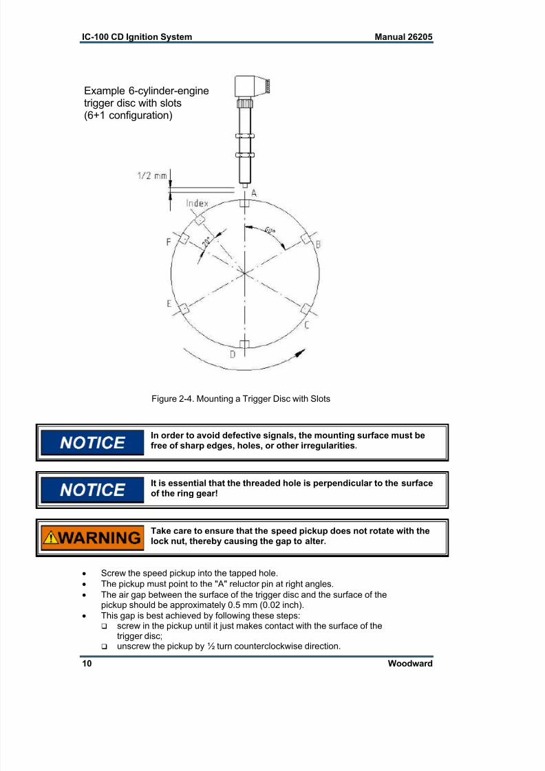
Figure 2-4. Mounting a Trigger Disc with Slots
In order to avoid defective signals, the mounting surface must befree of sharp edges, holes, or other irregularities.
It is essential that the threaded hole is perpendicular to the surfaceof the ring gear!
Take care to ensure that the speed pickup does not rotate with the
lock nut, thereby causing the gap to alter.
Screw the speed pickup into the tapped hole.
The pickup must point to the "A" reluctor pin at right angles.
The air gap between the surface of the trigger disc and the surface of thepickup should be approximately 0.5 mm (0.02 inch).
This gap is best achieved by following these steps: screw in the pickup until it just makes contact with the surface of the
trigger disc; unscrew the pickup by ½ turn counterclockwise direction.
Example 6-cylinder-enginetrigger disc with slots(6+1 configuration)

7/24/2019 IC-100 CD Ignation
http://slidepdf.com/reader/full/ic-100-cd-ignation 17/60
Manual 26205 IC-100 CD Ignition System
Woodward 11
Now tighten the lock nut, taking care to ensure that the pickup does notrotate at the same time.
Crank the engine back and forth several times by a few degrees to makesure that the pickup does not strike the trigger disc.
Flywheel Pickup
The flywheel pickup senses an ac signal if a passive pickup is used.
Mounting Location
A massive and vibration-free bracket must be prepared for the speed pickup.
Preparations
Drill and tap a hole to accept the magnetic pickup.This hole must be drilled in such a way that the pickup is directed towardsthe surface of the trigger disc at right angle.
Ensure that metal chips, filings, or shavings from drilling and tappingoperations do not remain in the engine!
It is essential that the threaded hole be perpendicular to the surfaceof the ring gear!
Installation
Screw the pickup into the threaded hole.The pickup must be precisely directed towards the center of the flywheel.The gap between its surface and the surface of the trigger disc must beapproximately 0.6 mm (0.02 inch).This gap is best achieved by screwing in the pickup unit until it just makescontact with the top of the trigger disc or flywheel, then unscrewing it one-half turn counterclockwise.
Fix the pickup in place by means of the lock nut.
Slowly crank the engine a full rotation to ensure that the disc does not strikethe pickup.
7/24/2019 IC-100 CD Ignation
http://slidepdf.com/reader/full/ic-100-cd-ignation 18/60
IC-100 CD Ignition System Manual 26205
12 Woodward
Figure 2-5. Mounting of Flywheel Pickup
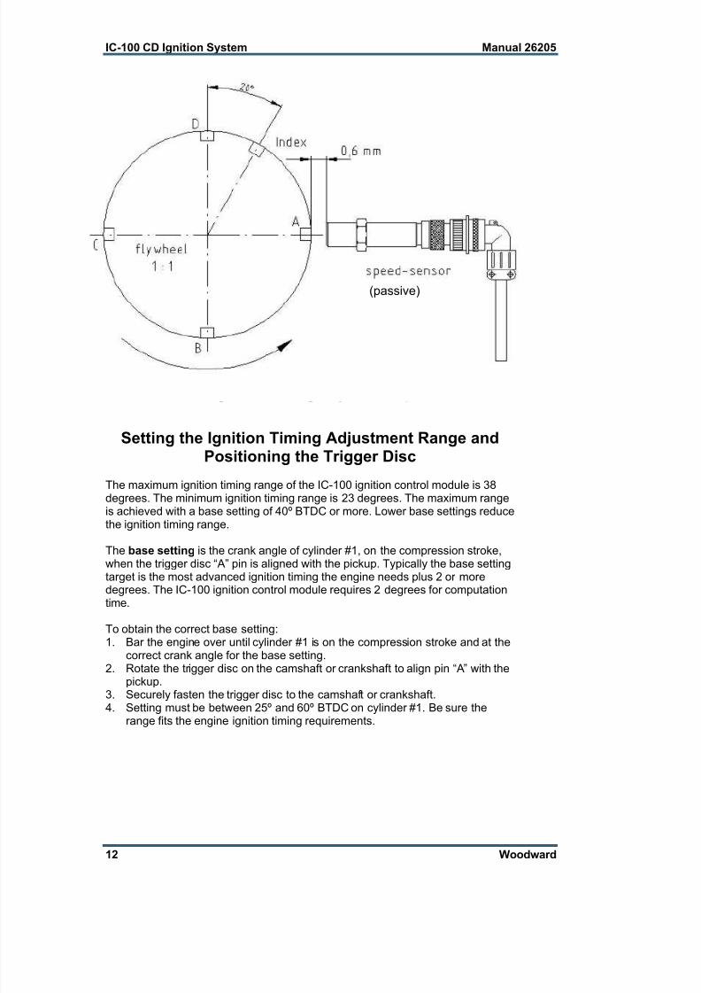
Setting the Ignition Timing Adjustment Range andPositioning the Trigger Disc
The maximum ignition timing range of the IC-100 ignition control module is 38degrees. The minimum ignition timing range is 23 degrees. The maximum rangeis achieved with a base setting of 40º BTDC or more. Lower base settings reduce
the ignition timing range.
The base setting is the crank angle of cylinder #1, on the compression stroke,when the trigger disc “A” pin is aligned with the pickup. Typically the base settingtarget is the most advanced ignition timing the engine needs plus 2 or moredegrees. The IC-100 ignition control module requires 2 degrees for computationtime.
To obtain the correct base setting:1. Bar the engine over until cylinder #1 is on the compression stroke and at the
correct crank angle for the base setting.2. Rotate the trigger disc on the camshaft or crankshaft to align pin “A” with the
pickup.
3. Securely fasten the trigger disc to the camshaft or crankshaft.4. Setting must be between 25º and 60º BTDC on cylinder #1. Be sure the
range fits the engine ignition timing requirements.
(passive)

7/24/2019 IC-100 CD Ignation
http://slidepdf.com/reader/full/ic-100-cd-ignation 19/60
Manual 26205 IC-100 CD Ignition System
Woodward 13
Figure 2-6. Example of Positioning of Flywheel
Ensure that the trigger disc is perfectly centered!
TDC
40o
The maximum advance for the ignition timing (º BTDC) is the base setting minusa 2 degree computation time. Maximum advance is limited to 58º BTDC.Maximum retard is limited to 0.0º BTDC.
Example A:Basic setting: 40° BTDC
Ignition adjustment range: 38° BTDC to 0° BTDC ( 38°)
Example B:Basic setting: 30° BTDC
Ignition adjustment range: 28° BTDC to 0° BTDC ( 28°)
40°
adjustment-range
38°
0°
flywheel
basic setting: 40° BTDC
ignition adjustmentrange: 38° BTDC to
0° BTDC

7/24/2019 IC-100 CD Ignation
http://slidepdf.com/reader/full/ic-100-cd-ignation 20/60
IC-100 CD Ignition System Manual 26205
14 Woodward
Example C: Basic setting: 50° BTDC
Ignition adjustment range: 48° BTDC to 10° BTDC 38°)
The system does not allow After Top Dead Center (ATDC) ignitiontiming.
Disposal of the Ignition Control System
The IC-100 is comprised of only a small amount of surplus refuse that may bedisposed of in the usual manner as industrial waste.
Wiring Requirements
General
This symbol identifies earth ground. It is to be used to connect the IC-100 to earth ground.
This symbol identifies chassis ground. This terminal is to be used forcable shield or for connecting the cable gland plates to the chassis.
To maintain compliance with CE marking requirements, the EMCdirective requires that all shields be connected to the terminals provided in theIC-100 according to the wiring diagram as in Figure 2-7. In addition, the IC-100must be connected to earth ground (engine) through the mounting hardware or avery short strap (25x76 mm/1x3” braid).
Wire exposed beyond the shield must be as short as possible.
IC-100 CD Ignition System Electrical Connections and PinFunctionality
The engine power supply must be disconnected and safeguardedagainst switching on before beginning any work on the IC-100. Donot make any power supply connections into live power circuits!
Never switch on the ignition control module without the output leadsconnected to the unit.
An improperly installed ignition system may lead to engine damageand could pose threat of personal injury to operators.
All components (ignition control module, ignition coils, and all leadscreens) must be grounded to ensure electromagnetic compatibility.

7/24/2019 IC-100 CD Ignation
http://slidepdf.com/reader/full/ic-100-cd-ignation 21/60
Manual 26205 IC-100 CD Ignition System
Woodward 15
Take care to ensure that the following minimum and maximumvoltages to the IC-100 are complied with:
Minimum 10 Vdc
Maximum 32 VdcInput voltages beyond these values might damage the IC-100.
Shutdown of the IC-100 is achieved by switching off the input power.Emergency shutdown devices must be rewired in order to switch offthe input power.
The IC-100 CD ignition system offers the option of RS-232 or CANBuscommunication. All input power, various I/O, and ignition coil output connectionare made through a 23 socket-pin plug connector.
RS-232 Port
The IC-100 may programmed via RS-232 using a null modem cable. Any faultindications will be transmitted to a PC/laptop through the RS-232 link.
CANBus
There are two modes for the CANBus: display (read only) and control(read/write). The write mode is enabled with the RS-232 programming mode“CAN BUS ENABLED”. For instructions on how to operate in this mode, pleasecontact the factory (see chapter 5 for instructions). With both modes, once theCANBus has active communication, the ESC key on the RS-232 does not work.This is to prevent conflicts between the CANBus writing configuration and that ofthe RS-232 port. This is important to remember if using the D-1 display tomonitor the cylinder energy because you cannot exit the cylinder-to-cylinder
adjustment or the energy screen using the ESC key.
In order for the CANBus to function properly, the correct CAN ID must be used.With the D-1 display, this number is 2. Please read the D-1 Display manual, ifyou require more information on its operation.
Input Power
Pins 13(+) and 12(–) connect the IC-100 to input power from an external powersource. The rated operating range is 18–32 Vdc (steady state operation from 10to 18 Vdc is allowable but may not be able to achieve 100% energy). Connectthe buffered positive power supply terminal through a 5 A Slo-Blo fuse to pin 13
of the harness and the reference to pin 12. To ensure proper operation, theminimum input voltage (18 V) must be maintained even under load. The cross-section of the power supply leads must be at least 2.5 mm² (14 AWG).
7/24/2019 IC-100 CD Ignation
http://slidepdf.com/reader/full/ic-100-cd-ignation 22/60
IC-100 CD Ignition System Manual 26205
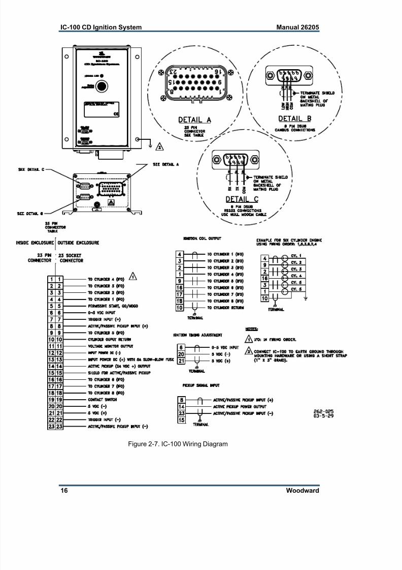
16 Woodward
Figure 2-7. IC-100 Wiring Diagram
7/24/2019 IC-100 CD Ignation
http://slidepdf.com/reader/full/ic-100-cd-ignation 23/60
Manual 26205 IC-100 CD Ignition System
Woodward 17
Ignition Timing Adjustment
The IC-100 features two stages of variable timing adjustment:
manual adjustment (potentiometer)
0–5 V analog signalPins 6(+), 20(–), and 21(+5 V) are used to receive a linear 0–5 Vdc signal fortiming control.
Each method is operator-adjustable and provides up to 38° adjustment range.The resolution of the timing setting is accurate to 0.25° crankshaft degrees.
Manual Adjustment
An incorrect timing setting may lead to engine damage!
The desired timing may be precisely set by manually rotating the potentiometer.Manual timing adjustment is possible with the engine running.
Do not apply voltage to terminals 6, 20, or 21 of the harness.
The desired timing setting may be obtained by rotating the potentiometer.The span between the extreme right and left position is max. 38° dependingon the configuration of the IC-100 (see Setting Potentiometer Span inChapter 3).
When choosing the correct timing setting, it is essential to strictlyadhere to the values specified by the engine manufacturer.
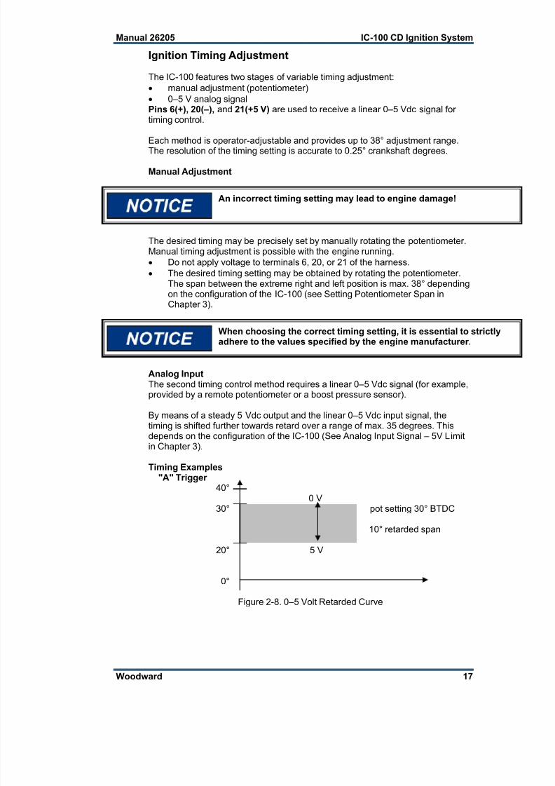
Analog InputThe second timing control method requires a linear 0–5 Vdc signal (for example,provided by a remote potentiometer or a boost pressure sensor).
By means of a steady 5 Vdc output and the linear 0–5 Vdc input signal, thetiming is shifted further towards retard over a range of max. 35 degrees. Thisdepends on the configuration of the IC-100 (See Analog Input Signal – 5V Limitin Chapter 3).
Timing Examples"A" Trigger
40°0 V
30° pot setting 30° BTDC
10° retarded span
20° 5 V
0°
Figure 2-8. 0–5 Volt Retarded Curve
7/24/2019 IC-100 CD Ignation
http://slidepdf.com/reader/full/ic-100-cd-ignation 24/60
IC-100 CD Ignition System Manual 26205
18 Woodward
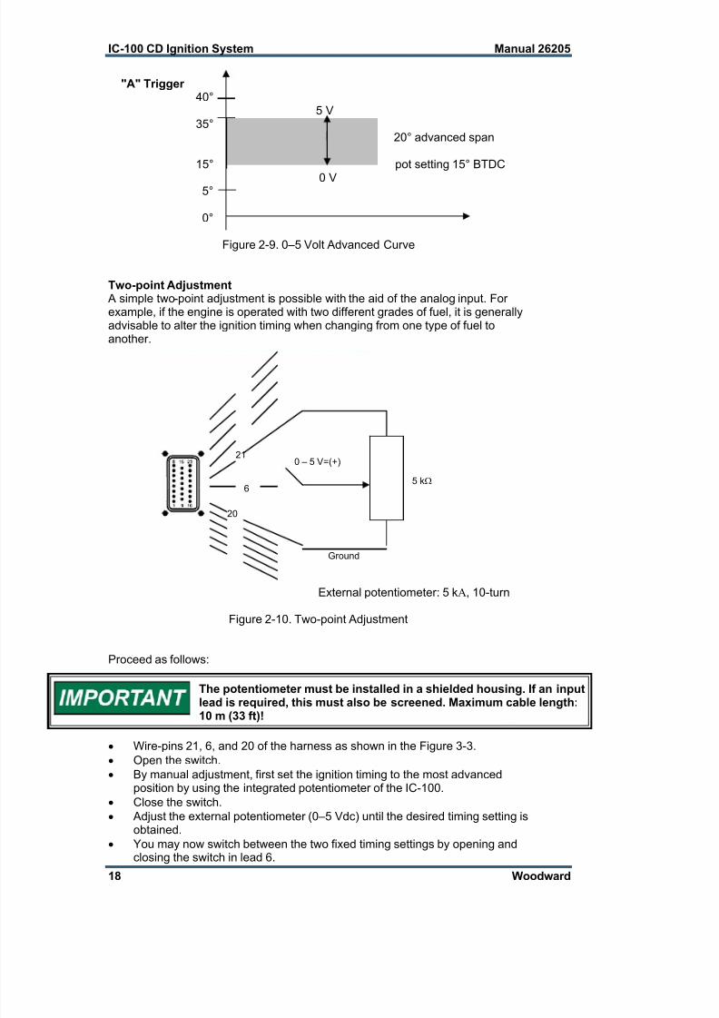
"A" Trigger40°
5 V35°
20° advanced span
15° pot setting 15° BTDC
0 V5°
0°
Figure 2-9. 0–5 Volt Advanced Curve
Two-point Adjustment A simple two-point adjustment is possible with the aid of the analog input. Forexample, if the engine is operated with two different grades of fuel, it is generallyadvisable to alter the ignition timing when changing from one type of fuel toanother.
External potentiometer: 5 k, 10-turn
Figure 2-10. Two-point Adjustment
Proceed as follows:
The potentiometer must be installed in a shielded housing. If an inputlead is required, this must also be screened. Maximum cable length:
10 m (33 ft)!
Wire-pins 21, 6, and 20 of the harness as shown in the Figure 3-3.
Open the switch.
By manual adjustment, first set the ignition timing to the most advancedposition by using the integrated potentiometer of the IC-100.
Close the switch.
Adjust the external potentiometer (0–5 Vdc) until the desired timing setting isobtained.
You may now switch between the two fixed timing settings by opening andclosing the switch in lead 6.
0 – 5 V=(+)
5 k
Ground
21
6
20

7/24/2019 IC-100 CD Ignation
http://slidepdf.com/reader/full/ic-100-cd-ignation 25/60
Manual 26205 IC-100 CD Ignition System
Woodward 19
integrated potentiometer setting28°
external potentiometer setting (0–5 Vdc)20°
Figure 2-11. Potentiometer Setting
Permissive Start
Pin 5 is the Permissive Start or Go/No Go output. It is a solid-state output,capable of sinking 150 mA, that should be used to enable/disable fuel flow to theengine directly or in combination with other devices (lube oil pressure, etc.).
Anytime the ignition stops due to normal stop sequence, over speed, or when afault is detected, the Permissive Start output will de-energize. Upon start-up, thePermissive Start output will not energize until all timing signals are verified andthe ignition is starting to fire. Figure 2-12 shows a likely set up for this output.
Figure 2-12. GO/NOGO Output
Contact Switch
Pin 19 can be set up as a switch between the timing schedules A or B. It canalso be configured as an Auxiliary Shutdown Input. This needs to beprogrammed using the RS-232. The default is for Auxiliary Shutdown.

7/24/2019 IC-100 CD Ignation
http://slidepdf.com/reader/full/ic-100-cd-ignation 26/60
IC-100 CD Ignition System Manual 26205
20 Woodward
Auxiliary Shutdown InputThe IC-100 provides a low voltage, low current means of shutting down theignition system using a PLC or similar device. If the contact switch is tied toground, the ignition outputs will not fire. If the contact is tied to ground above thesecurity speed (above cranking speed, but below idle), it is necessary for the rpmto go to zero before the outputs will fire. If the contact is open below the securityspeed, the ignition will fire immediately if the trigger, reset, and cam signals arecorrect.
Do not use the Auxiliary Shutdown input as a primary shutdowndevice. Be sure to have a separate and independent shutdowndevice.
Timing Schedules A or BTwo different timing schedules can be programmed to be accepted by the IC-100. The contact switch is then configured to select between the two schedules.It is possible to change timing schedules while running.
Monitor
Pin 11 is a voltage output of the voltage present at the internal capacitor used toignite the coils. The ratio is a function of the impedance of the meter. For a 10MΩ meter impedance, the ratio is 9.23:1; and for a 1 MΩ, it is 10.2:1.
Trigger
Pins 7(+), and 22(–) are for the trigger timing signal. The ignition control modulecompares the trigger timing signal with the preprogrammed pin count and thefiring patterns. Should any discrepancy occur, the ignition control module willshut down following one further complete revolution of the flywheel.
Pickup Signal Input
Pins 8(+), and 23(–) are used to receive either an active or passive pickupsignal. Pin 14(active pickup power) also provides power to the active pickupunit equal to 1 V less than the power provided to the input terminals (pins 13 &12). Pin 15 can be used for the shield of this input. See Tables 2-1 and 2-2 forrecommended connections.
connector pole function
8 passive pickup (+)
23 passive pickup (–)
chassis ground shielding
21 5 Vdc output
6 analog input
20 (–) signal ground
19 contact switch
5 permissive start
13 input power dc (+)
12 input power dc (–)
Table 2-1. Input Wiring with Passive Pickup
7/24/2019 IC-100 CD Ignation
http://slidepdf.com/reader/full/ic-100-cd-ignation 27/60
Manual 26205 IC-100 CD Ignition System
Woodward 21
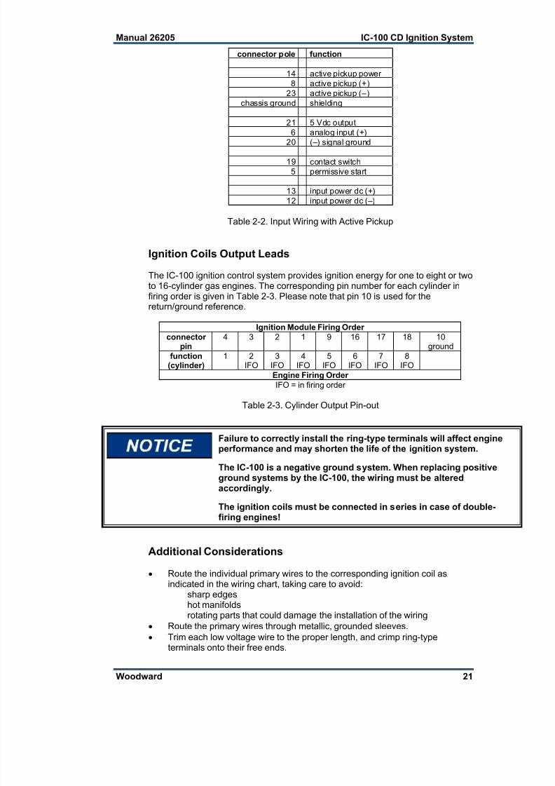
connector pole function
14 active pickup power
8 active pickup (+)
23 active pickup (–)
chassis ground shielding
21 5 Vdc output
6 analog input (+)
20 (–) signal ground
19 contact switch
5 permissive start
13 input power dc (+)
12 input power dc (–)
Table 2-2. Input Wiring with Active Pickup
Ignition Coils Output Leads
The IC-100 ignition control system provides ignition energy for one to eight or twoto 16-cylinder gas engines. The corresponding pin number for each cylinder infiring order is given in Table 2-3. Please note that pin 10 is used for thereturn/ground reference.
Ignition Module Firing Order
connectorpin
4 3 2 1 9 16 17 18 10ground
function(cylinder)
1 2IFO
3IFO
4IFO
5IFO
6IFO
7IFO
8IFO
Engine Firing Order
IFO = in firing order
Table 2-3. Cylinder Output Pin-out
Failure to correctly install the ring-type terminals will affect engineperformance and may shorten the life of the ignition system.
The IC-100 is a negative ground system. When replacing positiveground systems by the IC-100, the wiring must be alteredaccordingly.
The ignition coils must be connected in series in case of double-firing engines!
Additional Considerations
Route the individual primary wires to the corresponding ignition coil asindicated in the wiring chart, taking care to avoid:
sharp edgeshot manifoldsrotating parts that could damage the installation of the wiring
Route the primary wires through metallic, grounded sleeves.
Trim each low voltage wire to the proper length, and crimp ring-typeterminals onto their free ends.

7/24/2019 IC-100 CD Ignation
http://slidepdf.com/reader/full/ic-100-cd-ignation 28/60
IC-100 CD Ignition System Manual 26205
22 Woodward
The ring-type terminals should be suitable for 1.5 mm² (16 AWG) wire andshould have a hole diameter of 5 mm (0.2 inch).
Use only proper crimping tools for attaching ring-type terminals.
Use the remaining primary wire or other wire (1.5 mm², temperatureresistance: up to 125 °C/257 °F; insulation breakdown strength: min. 600 V)along with the ring-type terminals to jumper the negative ignition coilterminals.
On each engine cylinder bank, the first and last coil must be grounded to theengine block.
Starting with cylinder 1, enter the engine firing order in Table 2-4 below. Alwaysrefer to the engine manufacturer's specifications for the correct firing order.
Output Wiring
Connector Pole Function
4 cylinder 1
3
2
1
9
16
17
18
10 ground
11 measuring output
Table 2-4. Ignition Firing Order
Spark plugs should be replaced for optimum ignition performance.Always follow the manufacturer's recommended gap setting andinstallation procedures.
If reusing high tension leads, make sure that they are free of breaks,cracks, oil contamination, or burns. Connectors must be clean andseat firmly.
Ignition Coils and High Tension Leads
HIGH VOLTAGE—Do not remove spark plug caps when the engine isrunning.
Securely mount each ignition coil on the engine as close to the spark plugas possible.
Avoid mounting the coils on or near hot manifolds or where ambienttemperatures exceed 100 °C (212 °F).
Ensure that the high tension leads are as short as possible.
Spark plug leads with integrated resistors (5 kΩ typical) arerecommended.
e n t e r f i r i n g o
r d e r
h e r e

7/24/2019 IC-100 CD Ignation
http://slidepdf.com/reader/full/ic-100-cd-ignation 29/60
Manual 26205 IC-100 CD Ignition System
Woodward 23
Chapter 3.Operation
Programming the IC-100 with a Laptop
In order to program the IC-100, it is necessary to download the “Ignition Systemtools” from www.woodward.com/ic/software. The software is designed forDOS. Install the software on your laptop according to the instructions.
When using a laptop, please note that commands are case-sensitive (capitalletters must be entered as capitals, using the [SHIFT]-key).
Programming the IC-100 with the Hand HeldProgrammer
Any hand held programmer needs to have the serial port configured for thefollowing:
Baud rate = 9600
Data bits = 7
No parity
The following instructions are unique for use only with the 9420-0006hand held programmer.
Before first use, the hand held programmer must be configured.
Switch on the programmer.
Press [SHIFT] + [CTRL] + [F1] at the same time.
The first parameter will be displayed.
Baud = 9600, press [F1] to continue in lines until "9600" is displayed.[F2] next
Data Bits = 7, press [F1] to continue in lines until "7" is displayed.[F2] next
Parity = ignore, press [F1] to continue in lines until "ignore" is displayed.[F2] next
Display Pre enabled, press [F1] to continue in lines until "enabled" is displayed.[F2] next
Repeat = fast, press [F1] to continue in lines until "fast" is displayed.[F2] next
Echo disabled, press [F1] to continue in lines until "disabled" is displayed.[F2] next
Handshake disabled, press [F1] to continue in lines until "disabled" is displayed.[F2] next
Self Test disabled, press [F1] to continue in lines until "disabled" is displayed.[F2] next

7/24/2019 IC-100 CD Ignation
http://slidepdf.com/reader/full/ic-100-cd-ignation 30/60
IC-100 CD Ignition System Manual 26205
24 Woodward
Power Save enabled, press [F1] ton continue in lines until "enabled" is displayed.[F2] next
[F5] Save
Now, the hand held programmer is ready for use. When programming with thehand held programmer, only capital letters are possible.
IC-100 Programming Overview
The following is a brief overview of the different screens available on an IC-100. A more detailed description follows under “Programmable parameters”.
(1) SEQ. Number See Configuration Table 3-1 in this chapter.Default is 23.
(2) Reset BTDC Position in crank angle degrees of trigger discbasic setting. Trigger pin / hole "A" is opposite topickup. Default is 25.
(3) Overspeed Overspeed value in rpm. When reached, ignition
will shut down. Default is 2200.
(4) Security Speed Speed that inhibits operation of the contactswitch. Default is 350.
(5) MISFIRE RATE Max. allowed misfiring rate. When exceeded,ignition will shut down. Default is 0.
(6) CAN ID # The range is from 1 to 31. Default is 2.
(7) CANBus enable CANBus function activated (R/W mode).CANBus disable CANBus function deactivated (Read only). This is
the default.
(8) cyl to cyl enable Enables cyl-to-cyl timing. This is the default.cyl to cyl disable Disables cyl-to-cyl timing.
(9) contact I/P – for stop Contact switch provides ON/OFF functionality(timing schedule A only). This is the default.
contact I/P – for A/B Contact switch provides timing scheduleselection (timing schedule A or B)
(10) Pot timing – enable Potentiometer function activated. This is thedefault.
Pot timing – disable Potentiometer function deactivated.
(11) speed curve in A – in A –enable Speed curve for timing schedule A activated.speed curve in A – not in A –
disable Speed curve for timing schedule A deactivated.This is the default.
(12) 0 – 5 V in A – in A - enable 0–5 V analog for timing schedule A activated.0 – 5 V in A – not in A - disable 0–5 V analog for timing schedule A deactivated.
This is the default.
1(13) speed curve in B – in B –
enable Speed curve for timing schedule B activated.speed curve in B – not in B –disable Speed curve for timing schedule B deactivated.
This is the default.
7/24/2019 IC-100 CD Ignation
http://slidepdf.com/reader/full/ic-100-cd-ignation 31/60
Manual 26205 IC-100 CD Ignition System
Woodward 25
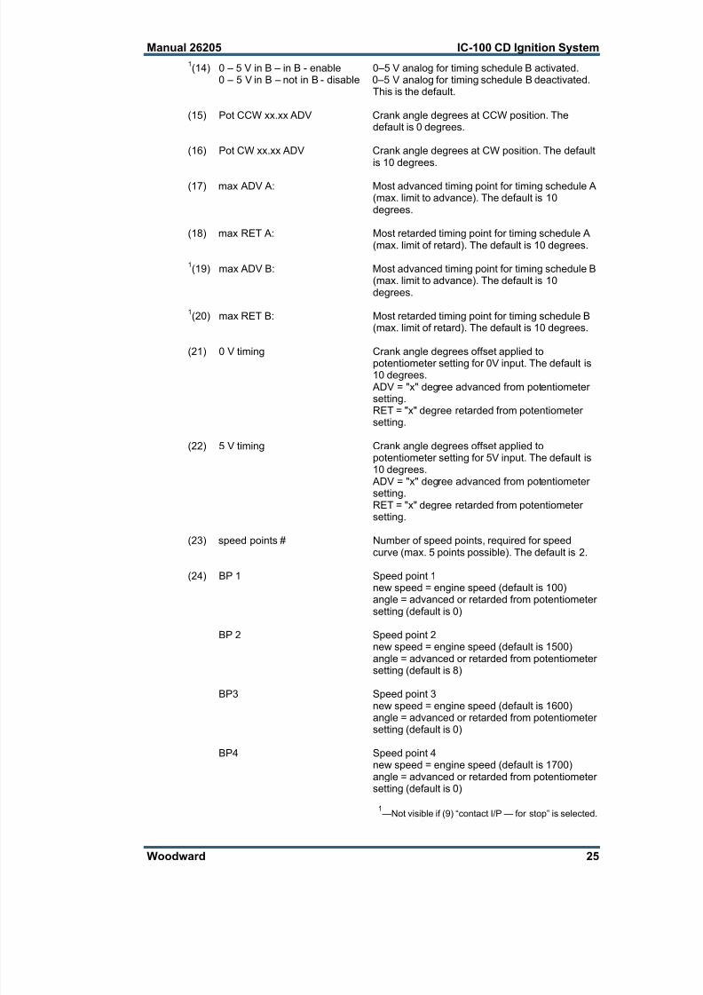
1(14) 0 – 5 V in B – in B - enable 0–5 V analog for timing schedule B activated.
0 – 5 V in B – not in B - disable 0–5 V analog for timing schedule B deactivated.This is the default.
(15) Pot CCW xx.xx ADV Crank angle degrees at CCW position. Thedefault is 0 degrees.
(16) Pot CW xx.xx ADV Crank angle degrees at CW position. The defaultis 10 degrees.
(17) max ADV A: Most advanced timing point for timing schedule A(max. limit to advance). The default is 10degrees.
(18) max RET A: Most retarded timing point for timing schedule A(max. limit of retard). The default is 10 degrees.
1(19) max ADV B: Most advanced timing point for timing schedule B
(max. limit to advance). The default is 10degrees.
1(20) max RET B: Most retarded timing point for timing schedule B
(max. limit of retard). The default is 10 degrees.
(21) 0 V timing Crank angle degrees offset applied topotentiometer setting for 0V input. The default is10 degrees.
ADV = "x" degree advanced from potentiometersetting.RET = "x" degree retarded from potentiometersetting.
(22) 5 V timing Crank angle degrees offset applied topotentiometer setting for 5V input. The default is10 degrees.
ADV = "x" degree advanced from potentiometersetting.RET = "x" degree retarded from potentiometersetting.
(23) speed points # Number of speed points, required for speedcurve (max. 5 points possible). The default is 2.
(24) BP 1 Speed point 1new speed = engine speed (default is 100)angle = advanced or retarded from potentiometersetting (default is 0)
BP 2 Speed point 2new speed = engine speed (default is 1500)angle = advanced or retarded from potentiometersetting (default is 8)
BP3 Speed point 3new speed = engine speed (default is 1600)angle = advanced or retarded from potentiometersetting (default is 0)
BP4 Speed point 4new speed = engine speed (default is 1700)angle = advanced or retarded from potentiometersetting (default is 0)
1—Not visible if (9) “contact I/P — for stop” is selected.
7/24/2019 IC-100 CD Ignation
http://slidepdf.com/reader/full/ic-100-cd-ignation 32/60
IC-100 CD Ignition System Manual 26205
26 Woodward
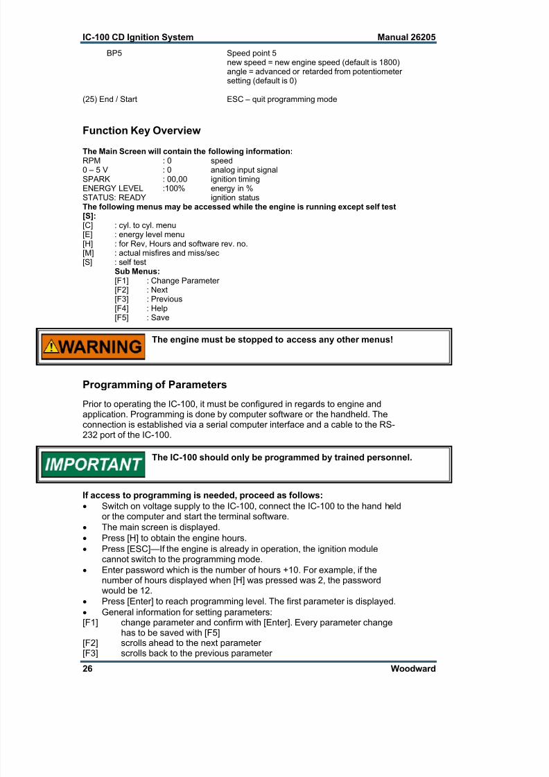
BP5 Speed point 5new speed = new engine speed (default is 1800)angle = advanced or retarded from potentiometersetting (default is 0)
(25) End / Start ESC – quit programming mode
Function Key OverviewThe Main Screen will contain the following information:RPM : 0 speed0 – 5 V : 0 analog input signalSPARK : 00,00 ignition timingENERGY LEVEL :100% energy in %STATUS: READY ignition status The following menus may be accessed while the engine is running except self test[S]:[C] : cyl. to cyl. menu[E] : energy level menu[H] : for Rev, Hours and software rev. no.[M] : actual misfires and miss/sec[S] : self test
Sub Menus:[F1] : Change Parameter[F2] : Next[F3] : Previous[F4] : Help[F5] : Save
The engine must be stopped to access any other menus!
Programming of Parameters
Prior to operating the IC-100, it must be configured in regards to engine andapplication. Programming is done by computer software or the handheld. Theconnection is established via a serial computer interface and a cable to the RS-232 port of the IC-100.
The IC-100 should only be programmed by trained personnel.
If access to programming is needed, proceed as follows:
Switch on voltage supply to the IC-100, connect the IC-100 to the hand heldor the computer and start the terminal software.
The main screen is displayed.
Press [H] to obtain the engine hours.
Press [ESC]—If the engine is already in operation, the ignition modulecannot switch to the programming mode.
Enter password which is the number of hours +10. For example, if thenumber of hours displayed when [H] was pressed was 2, the passwordwould be 12.
Press [Enter] to reach programming level. The first parameter is displayed.
General information for setting parameters:[F1] change parameter and confirm with [Enter]. Every parameter change
has to be saved with [F5][F2] scrolls ahead to the next parameter[F3] scrolls back to the previous parameter

7/24/2019 IC-100 CD Ignation
http://slidepdf.com/reader/full/ic-100-cd-ignation 33/60
Manual 26205 IC-100 CD Ignition System
Woodward 27
[F4] displays a short clarification of the current parameter[F5] save parameter[ESC] quit programming level and start IC-100[F10] quit program (PC only)
Hit [ESC] to exit programming mode before exiting [F10] the DOSprogram for PC only OR disconnect the hand held.
After setting IC-100 parameters, we recommend switching off the supply voltagein order to reset the IC-100. If the CANBus is activated, the supply voltage mustbe switched off, since the ignition will be started in a different mode. Leave thesupply voltage off for at least 20 seconds to ensure that all possible faults arereset.
All programmable parameters must be set according to the engine applicationbefore operation.
Some of the submenus are available when engine is running:[C] : cyl. to cyl. menu[E] : energy level menu[H] : for Rev, Hours and software rev. no.
[M] : actual misfires and miss/sec
Programmable Parameters
(1) SEQ. NumberIC-100 Sequence Table
SequenceNo.
No. ofOutputs
MagnetDisc
FiringDegrees
DiscLocation
Unit FiringOrder
1 2 2 + 1 360-360 cam A-B
2 3 3 + 1 240-240 cam A-B-C
3 3 3 + 1 120-120 crank A-B-C
4 6 3 + 1 50-70 crank A-B-C-D-E-F
5 6 3 + 1 30-90 crank A-B-C-D-E-F6 6 3 + 1 90-30 crank A-B-C-D-E-F
7 2 4 + 1 90-90 crank A-B
8 4 4 + 1 180-180 cam A-B-C-D
9 4 4 + 1 90-90 crank A-B-C-D
10 8 4 + 1 20-70 crank A-B-C-D-E-F-G-H
11 8 4 + 1 60-30 crank A-B-C-D-E-F-G-H
12 8 4 + 1 45-45 crank A-B-C-D-E-F-G-H
13 8 4 + 1 30-60 crank A-B-C-D-E-F-G-H
14 5 5 + 1 72-72 crank A-B-C-D-E
15 5 5 + 1 144-144 cam A-B-C-D-E
16 6 6 + 1 120-120 cam A-B-C-D-E-F
17 3 * 6 + 1 60-180 crank A-B-E
18 4 * 6 + 1 120-60 crank A-C-D-F19 6 6 + 1 60-60 crank A-B-C-D-E-F
20 7 7 + 1 102.8-102.8 cam A-B-C-D-E-F-G
21 7 7 + 1 51.43-51.43 crank A-B-C-D-E-F-G
22 8 8 + 1 90-90 cam A-B-C-D-E-F-G-H
23 8 8 + 1 45-45 crank A-B-C-D-E-F-G-H
24 2 * 6 + 1 360-360 cam A-D
25 3 * 6 + 1 240-240 cam A-C-E
26 4 * 6 + 1 180-180 cam A-D-E-H
27 8 6 + 1 120-60 cam A-B-C-D-E-F-G-H
7/24/2019 IC-100 CD Ignation
http://slidepdf.com/reader/full/ic-100-cd-ignation 34/60
IC-100 CD Ignition System Manual 26205
28 Woodward
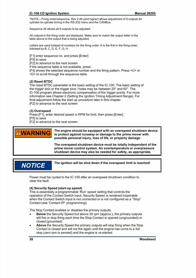
*NOTE—Firing order/sequence. Rev 2.46 (and higher) allows adjustment of 6 outputs forcylinder-to-cylinder timing in the RS-232 menu and the CANBus.
Sequence 26 allows all 8 outputs to be adjusted.
All outputs in the firing order are displayed. Make sure to match the output letter in thetable above to the output that is being adjusted.
Letters are used instead of numbers for the firing order: A is the first in the firing order,
followed by B, C, D, E, F, G, H.
[F1] enter sequence no. and press [Enter][F5] to save[F2] to advance to the next screenIf the sequence table is not available, press:[F4] shows the selected sequence number and the firing pattern. Press <U> or<D> to scroll through the sequence table.
(2) Reset BTDCThe reset BTDC parameter is the basic setting of the IC-100. The basic setting ofthe trigger disc or the trigger pins / holes may be between 25° and 60°. TheIC-100 program allows electronic compensation of the trigger points. For more
information see Chapter 2 (Setting the Ignition Timing Adjustment Range). Forfinal adjustment follow the start up procedure later in this chapter.[F2] to advance to the next screen
(3) OverspeedPress [F1], enter desired speed in RPM for limit, then press [Enter].[F5] to save[F2] to advance to the next screen
The engine should be equipped with an overspeed shutdown deviceto protect against runaway or damage to the prime mover withpossible personal injury, loss of life, or property damage.
The overspeed shutdown device must be totally independent of theprime mover control system. An overtemperature or overpressureshutdown device may also be needed for safety, as appropriate.
The ignition will be shut down if the overspeed limit is reached!
Power must be cycled to the IC-100 after an overspeed shutdown condition toclear the fault.
(4) Security Speed (start-up speed)This is essentially a programmable ‘Run’ speed setting that controls the
operation of the Contact Switch input. Security Speed is rendered inoperablewhen the Contact Switch input is not connected or is not configured as a “Stop”Contact (see ‘Contact I/P’ programming).
The Stop Contact enables or disables the primary outputs.
Below the Security Speed but above 30 rpm (approx.), the primary outputswill fire or stop firing each time the Stop Contact is opened (ungrounded) orclosed (grounded).
Above the Security Speed the primary outputs will stop firing when the StopContact is closed and will not fire again until the engine has come to a fullstop (zero rpm is sensed) and the engine is re-started.
7/24/2019 IC-100 CD Ignation
http://slidepdf.com/reader/full/ic-100-cd-ignation 35/60
Manual 26205 IC-100 CD Ignition System
Woodward 29
Above the Security Speed the primary outputs will fire if the Stop Contactwas closed and is opened for the first time. This allows engine starting whenthe Security Speed is set below cranking speed.
Typically the Security Speed is set above cranking speed and below minimum oridle speed.
Programming Sequence:
1. Press F1 to change security speed or F2 to skip.2. Enter security speed, then press ENTER.3. Press F5 to save.4. Press F2 to program next parameter.Range: Valid from 0 rpm to ‘overspeed’ rpm setting.
(5) Misfire RateThe number of misses per second that is permissible before the engine shutsdown due to misfire rate exceeded. To disable, set misfire rate to zero or 255.The most sensitive setting is 1. Please note that damaged leads may causemisfires.1. Press F1 to change misfire rate or F2 to skip.2. Enter misfire rate, then press ENTER.
3. Press F5 to save.4. Press F2 to program next parameter.
Disabling this function may cause personal injury or engine damage.
(6) CAN-ID # Specify desired CANBus protocol. The default is 2 which allows communicationwith a D1 display.
[F1]CAN ID #
1ST TYPE NEW: Please enter “2”.ENTER WHEN DONE Press [Enter][F5] to save[F2] to advance to the next screen
(7) CAN BUS ENABLED / DISABLEDThe CANBus function should only be activated if an engine management systemcontrols the ignition timing via CANBus.
[F1]ENABLED activatedDISABLED deactivated[F5] to save[F2] to advance to the next screen
Contact the factory for the CANBus communication protocol.
(8) Cylinder-to-Cylinder Timing (toggle with [F1])IC-100 units are equipped with cylinder-to-cylinder timing adjustment capability.This allows fine tuning of each cylinder ignition timing, individually. See Chapter 3(Additional Functions).
[F1] ENABLE activate[F2] DISABLE deactivate[F5] save

7/24/2019 IC-100 CD Ignation
http://slidepdf.com/reader/full/ic-100-cd-ignation 36/60
IC-100 CD Ignition System Manual 26205
30 Woodward
(9) Function of Contact Lead 19Contact lead 19 allows choice between two functions:
CONTACT I/P FOR STOP A/BF1F1 CONTACT FOR STOP Ignition can be STOPPED and STARTED via
this lead
F2 CONTACT FOR A/B Switching this lead allows shifting between 2timing schedules, A or B. A or B can havedifferent timing for the potentiometer and 0–5Volt. It is possible to have a speed curveenabled or disabled for both A and B schedules.
(10)Activating PotentiometerThe integrated potentiometer of the IC-100 can be disabled after making thesettings, in order to lock this feature for the operator.
POT TIMING ENABLED / DISABLEDF1ENABLE activated
DISABLE deactivatedF5 save
(11) Speed Curve in Timing Schedule AThe IC-100 offers programming of a speed curve / speed ramp. That means,depending on the actual engine speed, a certain timing is chosen. This aims atreaching optimal gas combustion.
SPEED CURVE IN A / NOT IN AF1ENABLE activated / function is usedDISABLE deactivated / function is not usedF5 save
(12) Analog Input Signal for Timing Schedule AIn addition to the potentiometer adjustment and the speed curve, it is possible tochange the ignition timing by using the analog input signal.
Example: A knock monitoring system can change the ignition timing linear. In that case theknock monitoring system sends the analog output signal 0–5 Vdc to the ignitionsystem depending on the level of engine knocking.
0 – 5 V IN A / NOT IN AF1ENABLE activated / function is usedDISABLE deactivated / function is not used
F5 save

7/24/2019 IC-100 CD Ignation
http://slidepdf.com/reader/full/ic-100-cd-ignation 37/60
Manual 26205 IC-100 CD Ignition System
Woodward 31
(13) Speed Curve in Timing Schedule BIt is possible to program a different speed curve / speed ramp for timing scheduleB. Thus a different ignition timing is given depending on actual engine speed.
By setting a speed dependent ignition timing an optimal gas combustion can beachieved.
SPEED CURVE IN B / NOT IN B
F1ENABLE activated / function is usedDISABLE deactivated / function is not usedF5 save
(14) Analog Input Signal for Timing Schedule B Additionally to the potentiometer adjustment and the speed curve it is possible tochange the ignition timing by using the analog input signal.
Example: A knock monitoring system can change the ignition timing linear. In that case theknock monitoring system sends the analog output signal 0–5 Vdc to the ignitionsystem depending on the level of engine knocking.
0 – 5 V IN B / NOT IN BF1ENABLE activated / function is usedDISABLE deactivated / function is not usedF5 save
(15) Setting the Potentiometer Span—CCW PositionThe left limit (CCW) of the potentiometer can be set as timing angle.
POT CCW x.xx ADVF11ST TYPE NEW enter valueF1: ADVANCE BTDC (before top dead center)F2: RETARD most retarded (0.00°)F5 save
(16) Setting Potentiometer Span—CW PositionThe right limit (CW) of the potentiometer can be set as timing angle.
POT CW x.xx ADVF11ST TYPE NEW enter valueF1: ADVANCE BTDC (before top dead center)F2: RETARD most retarded (0.00°)F5 save

7/24/2019 IC-100 CD Ignation
http://slidepdf.com/reader/full/ic-100-cd-ignation 38/60
IC-100 CD Ignition System Manual 26205
32 Woodward
Ignition Timing
25°
20°CCW position
10° CW position
50 500 1000 1500 RPM
(17) Timing Schedule A—Maximum Limit of Advanced IgnitionIn order to avoid engine damage by addition of the various ignition relevantparameters, it is possible to set a maximum ignition limit.
MAX ADV IN A: xx.xx ADVF11ST TYPE NEW: enter valueTHEN ENTER press [ENTER]F1: ADVANCE BTDC (before top dead center)F2: RETARD most retarded (0.00°)F5 save
(18) Timing Schedule A—Maximum Limit Retarded IgnitionIn order to avoid engine damage by addition of the various ignition relevantparameters, it is possible to set a minimum ignition limit.
MIN ADV IN A: xx.xx ADVF1
1ST TYPE NEW: enter valueTHEN ENTER press [ENTER]F1: ADVANCE BTDC (before top dead center)F2: RETARD most retarded (0.00°)F5 save
Ignition Timing
25° MAX limit
20°
10° MIN limit
50 500 1000 1500 RPM
potentiometer-span
7/24/2019 IC-100 CD Ignation
http://slidepdf.com/reader/full/ic-100-cd-ignation 39/60
Manual 26205 IC-100 CD Ignition System
Woodward 33
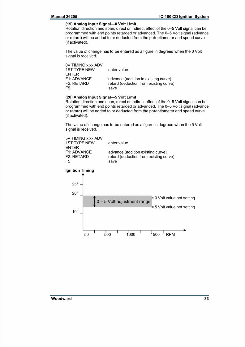
(19) Analog Input Signal—0 Volt LimitRotation direction and span, direct or indirect effect of the 0–5 Volt signal can beprogrammed with end points retarded or advanced. The 0–5 Volt signal (advanceor retard) will be added to or deducted from the potentiometer and speed curve(if activated).
The value of change has to be entered as a figure in degrees when the 0 Voltsignal is received.
0V TIMING x.xx ADV1ST TYPE NEW enter valueENTERF1: ADVANCE advance (addition to existing curve)F2: RETARD retard (deduction from existing curve)F5 save
(20) Analog Input Signal—5 Volt LimitRotation direction and span, direct or indirect effect of the 0–5 Volt signal can beprogrammed with end points retarded or advanced. The 0–5 Volt signal (advanceor retard) will be added to or deducted from the potentiometer and speed curve(if activated).
The value of change has to be entered as a figure in degrees when the 5 Voltsignal is received.
5V TIMING x.xx ADV1ST TYPE NEW enter valueENTERF1: ADVANCE advance (addition existing curve)F2: RETARD retard (deduction from existing curve)F5 save
Ignition Timing
25°
20°= 0 Volt value pot setting
= 5 Volt value pot setting10°
50 500 1000 1500 RPM
0 – 5 Volt adjustment range

7/24/2019 IC-100 CD Ignation
http://slidepdf.com/reader/full/ic-100-cd-ignation 40/60
IC-100 CD Ignition System Manual 26205
34 Woodward
Ignition Timing
25° = 5 Volt value pot setting
20° = 0 Volt value pot setting
10°
50 500 1000 1500 RPM
(21) Speed PointsFor programming a speed dependent curve max. speed of 5 points can be set.The speed curve should be worked out before you start programming the data!
SPEED POINTS: x1ST TYPE NEW: enter valueENTER WHEN DONE press [ENTER]F5 save
(22) Setting Speed Points BP1 to BP5Setting the speed points always requires a speed and a degree value. Thedegree value will be added to (ADV) or deducted from (RET) the potentiometercurve which is always 0 (zero).
BP1: x.xx ADVNEW SPEED enter speedENTER WHEN DONE press [ENTER]F1: ADVANCE addF2: RETARD deduct
Follow these instructions for the remaining speed points.
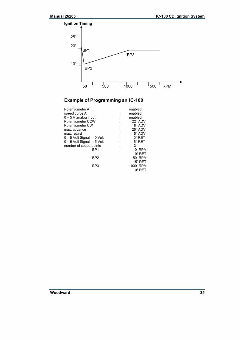
Example of a typical speed curve of an engine (generator operation) with aspeed curve to influence the start-up procedure positively:
When the engine is not running, the ignition timing is equal to the potentiometersetting. Thus the ignition timing can also be checked with the programmer or alaptop when the engine is out of operation. Even if the engine is started theignition timing will be reduced and increased again from 50 revolutions until itreaches the preset value at 1000 revolutions.
SPEED POINTS : 3 number of speed pointsBP1 : 0 speed
0 ADV angleF5BP2 : 50 speed
10 RET angleF5BP3 : 1000 speed
0 ADV angleF5
0 – 5 Volt adjustment range
7/24/2019 IC-100 CD Ignation
http://slidepdf.com/reader/full/ic-100-cd-ignation 41/60
Manual 26205 IC-100 CD Ignition System
Woodward 35
Ignition Timing
25°
20°BP1
BP3
10°BP2
50 500 1000 1500 RPM
Example of Programming an IC-100
Potentiometer A : enabledspeed curve A : enabled
0 – 5 V analog input : enabledPotentiometer CCW : 22° ADVPotentiometer CW : 18° ADVmax. advance : 25° ADVmax. retard : 5° ADV0 – 5 Volt Signal - 0 Volt : 0° RET0 – 5 Volt Signal - 5 Volt : 5° RETnumber of speed points : 3
BP1 : 0 RPM0° RET
BP2 : 50 RPM15° RET
BP3 : 1000 RPM0° RET

7/24/2019 IC-100 CD Ignation
http://slidepdf.com/reader/full/ic-100-cd-ignation 42/60
IC-100 CD Ignition System Manual 26205
36 Woodward
Enter your programmed data here:
°crank
35°
30°
25°
20°
15°
10°
5°
TDC0 50 1000 1500 1800 RPM
7/24/2019 IC-100 CD Ignation
http://slidepdf.com/reader/full/ic-100-cd-ignation 43/60
Manual 26205 IC-100 CD Ignition System
Woodward 37
Additional Functions
Ignition Energy Levels
Depending on the gas quality and the application, it is possible to vary theavailable ignition energy.
You may set any value between 20–100%.
Fast-burning gases like propane require relatively small energy, whereas slow-burning gases like sewage gas require high energy, to ignite the gas.
To change the preset values proceed as follows:
press "E"
press "F1"
enter new value
press "Enter"
press "F5" to save changes
Cylinder-to-Cylinder Timing
The cylinder-to-cylinder timing allows changing the adjustment for singlecylinders, to optimize ignition firing.
The ignition timing of each cylinder can be shifted by ±2° from the global setting.
However, you should use this option only if suitable instrumentation is availableto analyze the position with the most effective compression, in order toimmediately judge the result.
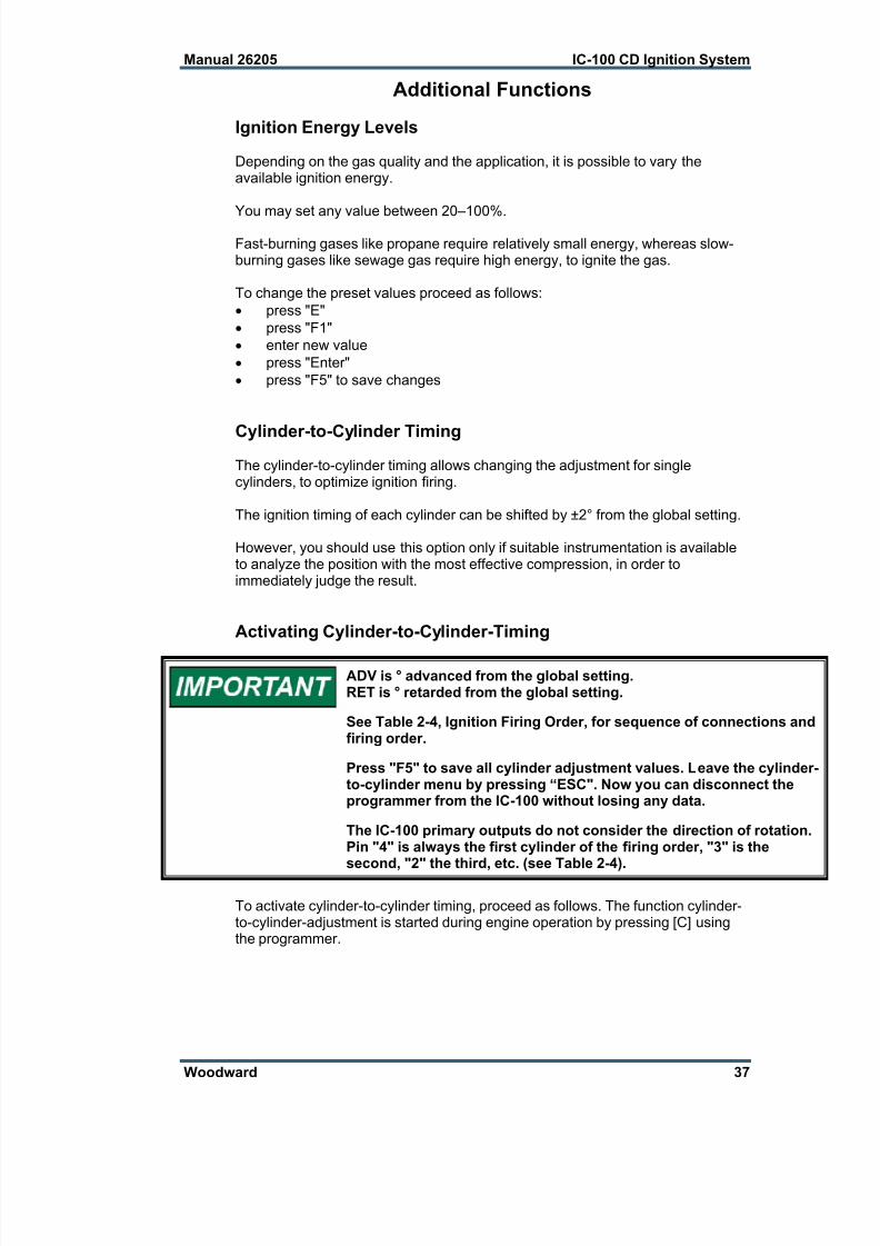
Activating Cylinder-to-Cylinder-Timing
ADV is ° advanced from the global setting.RET is ° retarded from the global setting.
See Table 2-4, Ignition Firing Order, for sequence of connections andfiring order.
Press "F5" to save all cylinder adjustment values. Leave the cylinder-to-cylinder menu by pressing “ESC". Now you can disconnect theprogrammer from the IC-100 without losing any data.
The IC-100 primary outputs do not consider the direction of rotation.Pin "4" is always the first cylinder of the firing order, "3" is thesecond, "2" the third, etc. (see Table 2-4).
To activate cylinder-to-cylinder timing, proceed as follows. The function cylinder-to-cylinder-adjustment is started during engine operation by pressing [C] usingthe programmer.
7/24/2019 IC-100 CD Ignation
http://slidepdf.com/reader/full/ic-100-cd-ignation 44/60
IC-100 CD Ignition System Manual 26205
38 Woodward
The following menu is displayed:
CYL #1 x.xx ADV / RETF1 CHANGE value can be changedF2 NEXT call next ignition outputF3 PREVIOUS back to previous outputF5 SAVE save
To change values proceed as follows:
[F2] until ignition output of the cylinder, which is to beoptimized, appears
[F1]1ST TYPE IN NEW enter delta value (max. 2°)THEN ENTER
[ENTER]
F1 ADVANCE change to position advanced from global settingF2 RETARD change to position retarded from global setting
F5 save
Initial Start-up Procedure
An improperly installed ignition system may lead to engine damageand could pose threat of personal injury to operators.
I. Before applying power to the IC-100, check and verify the following: 1. Fuel valve is shut off.2. The firing interval (sequence number) is correct for the engine type. If you
are not sure, contact your engine manufacturer.3. Cylinder firing order is known and the ignition coils are wired to the correct
outputs in accordance with the Cylinder Output Pin-out Table 2-3.4. Timing sensor is properly gapped and tightened.5. Timing sensor is wired in accordance with Table 2-1 or Table 2-2.
II. Apply power to the IC-100 (fuel valve still in the off position): 1. Check and verify that the IC-100 is programmed correctly.2. Perform the normal engine start-up procedure (prelube, etc.), except that the
fuel must remain OFF.3. With a timing light connected to the #1 cylinder, verify that the cylinder is
firing within ±2 degrees of the programmed setting. If not, refer to Chapter 4.4. Check all remaining cylinders for proper timing. If not correct, stop the engine
and recheck wiring and sequence number for correctness.5. Disengage the starter. Continue with step III if no problems are encountered.

7/24/2019 IC-100 CD Ignation
http://slidepdf.com/reader/full/ic-100-cd-ignation 45/60
Manual 26205 IC-100 CD Ignition System
Woodward 39
III. Set the fuel valve to its normal position.1. Follow the normal starting procedure and start the engine.2. If the engine fails to start, refer to Chapter 4.3. If the engine starts, re-verify timing of #1 cylinder.4. Increase engine speed to normal operating speed.5. Check timing of #1 cylinder and compare measured timing to the displayed
timing (PC/laptop with monitor program or hand held terminal is required).6. If the IC-100 displayed value is too high, the programmed reset position
(Reset BTDC parameter)needs to be reduced by the difference.
Example: If the IC-100 monitor is displaying 22.0° BTDC and the actual measuredtiming is 20.5° BTDC, the programmed reset position will have to bereduced by 1.5 degrees (22–20.5). So, if the programmed reset position(Reset BTDC parameter) is 50 degrees Adv., the programmed reset positionwill have to be changed to 48.5 degrees Adv.
If the IC-100 displayed value is too low compared to the measured timing,the programmed reset position will have to be increased by the difference.
7. If necessary, stop the engine using the normal shutdown procedure and
change the programmed reset position (Reset BTDC parameter).8. Re-start the engine and verify that the #1 cylinder is firing at the correctposition.
9. Check all remaining cylinders for proper timing. If not correct, stop the engineimmediately and recheck wiring and sequence number for correctness.

7/24/2019 IC-100 CD Ignation
http://slidepdf.com/reader/full/ic-100-cd-ignation 46/60
IC-100 CD Ignition System Manual 26205
40 Woodward
Chapter 4.Maintenance and Troubleshooting
Maintenance
Switch off the engine and disconnect the power supply beforecommencing any installation work!
An improperly installed ignition system may lead to engine damageand could pose threat of personal injury to operators.
The IC-100 ignition control module is not intended for repair by the end user. SeeChapter 5 for service options.
The remaining parts of the ignition control system should be serviced as follows:
The pickups might need to be replaced if they operate under extremethermal conditions (> 90 °C/194 °F).
All control system cables should be carefully examined for signs of damageand replaced if necessary.
All plug connections should be checked to ensure that they are in aserviceable condition.
The spark plugs should be serviced according to the specifications of thespark plug and engine manufacturer.
Faults and Troubleshooting
The IC-100 includes an LED, which indicates faults by flashing once or severaltimes.
flashing system status possible problemcontinuous flashing normal operation with ignition
firingnone
1 flash normal READY mode, 0 rpm none
1 flash no pickup signal defective pickup or incorrect wiringof pickup
2 flashes bad pickup signal sequence number does not matchtiming
3 flashes engine speed too low increase cranking speed / checksequence number and timing disc
4 flashes engine overspeed engine overspeed or set point toolow
5 flashes low supply voltage defective supply/battery orundersized wire
6 flashes programming mode none6 flashes configuration error incorrect parameters programmed,bad data identified in non-volatilememory, bad pickup signal at >
200 rpm
Table 4-1. LED Flash Codes

7/24/2019 IC-100 CD Ignation
http://slidepdf.com/reader/full/ic-100-cd-ignation 47/60
Manual 26205 IC-100 CD Ignition System
Woodward 41
The ignition system is comprised of the following components that have to betaken into consideration when searching for faults:
ignition control module
harness
ignition coils
high tension leads
ground leads
spark plugs
shutdown equipment
Most ignition system failures occur outside the ignition control module. The causemay lie in any one of the above components or in the connections between them.
The following troubleshooting guide is divided into three sections:
input fault diagnosis
low or high voltage ignition circuits
ignition control module self test function
Input Fault Diagnosis
If a fault is detected in the inputs to the IC-100, the ignition control module willautomatically shut down the ignition. The cause of the fault must be correctedbefore the engine can be restarted.
Input faults which might cause shutdown are:
open circuit or short-circuit to ground in the input power circuit
open circuit or short-circuit to ground in the engine starting circuit
loss of input power or supply voltage too low
Power supply circuit:
Supply voltages below the specified values will impair the operation
of the ignition control module and may cause the engine to stall.Supply voltages above the specified values could damage theignition control module.
The following minimum and maximum input voltages must bemaintained:
Minimum 10 VdcMaximum 32 Vdc
Input voltages outside these values may damage the IC-100.
If damping of the supply voltage is suspected, verify with a voltmeter. Check thestart/stop circuit for any opens, shorts or accidental connections to ground.
Faulty pickup signal:If a timing signal fault is detected during operation, the ignition control moduleautomatically shuts down the ignition. Such a fault could result from the failure ofa pickup, an open, short-circuited, or grounded connection to a pickup, or aphysical change in the characteristics of a passive trigger.
Proceed as follows:
Crank the engine with the fuel valve closed and check all signals at thepickup connectors using an oscilloscope.
Verify minimum 2.5 V square wave signal.

7/24/2019 IC-100 CD Ignation
http://slidepdf.com/reader/full/ic-100-cd-ignation 48/60
IC-100 CD Ignition System Manual 26205
42 Woodward
Figure 4-1. Oscilloscope—Square Wave Signal
Two LEDs are installed in the connector cap of the reset pickup. Thecolors indicate the following:
green—power supply connectedorange—trigger signal
Low or High Voltage Ignition Circuits
Track the ignition circuit current flow if the engine is missing on one or morecylinders, but not completely dead.
Apply an inductive timing light to the high tension leads to determine which
cylinder is not firing.
The brightness of the firing indicator bulb is not a measure of theactual strength of the respective output signal; it only reflects thevoltage required by the spark plug itself.
Determine which lead in the harness is connected to the malfunctioning cylinder.
Stop the engine and unplug the output harness connector from the ignitioncontrol module.
Use an ohmmeter with a scale of R x 1.
Connect one ohmmeter probe to the harness connector pin of themalfunctioning cylinder and the other to the engine ground.
Read the measured resistance.The resistance on the low voltage side should lie within the values specifiedbelow.If this is the case, the low voltage ignition circuit is not the cause of the fault.
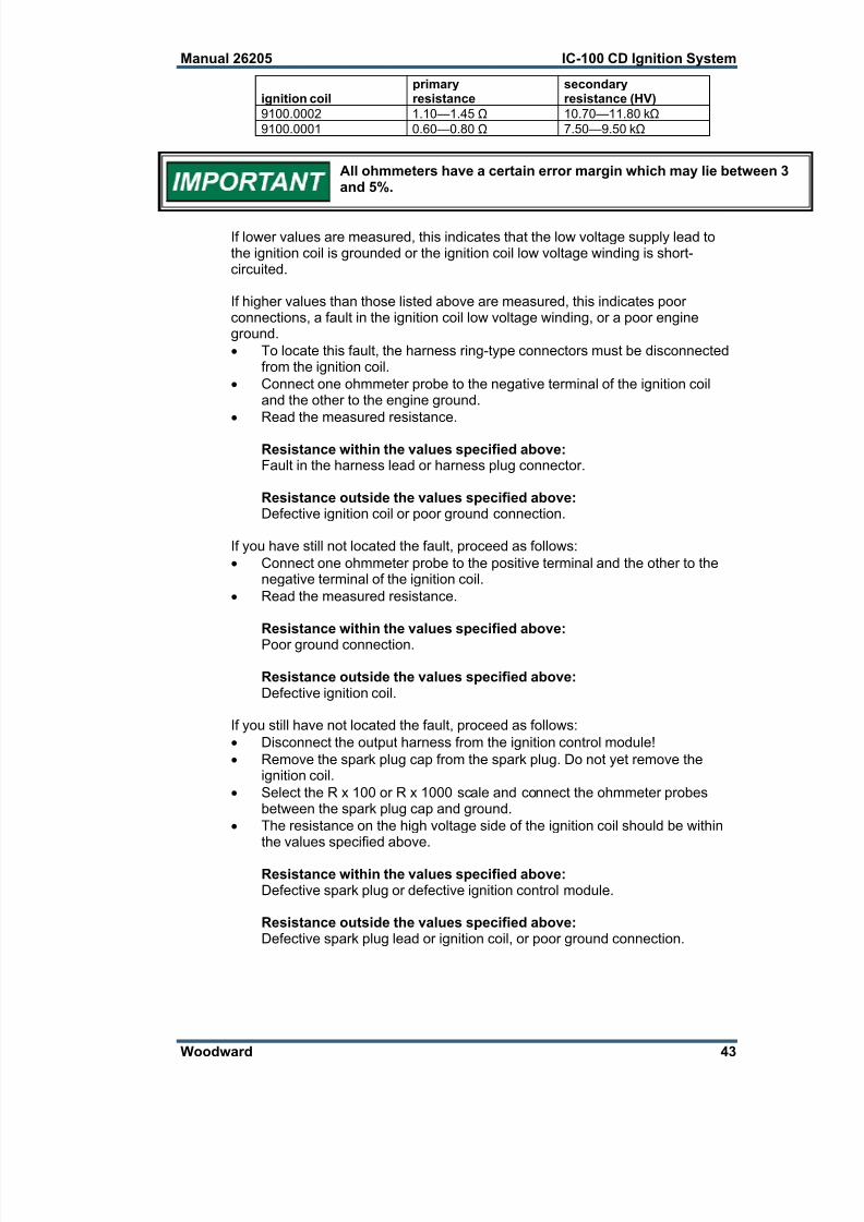
7/24/2019 IC-100 CD Ignation
http://slidepdf.com/reader/full/ic-100-cd-ignation 49/60
Manual 26205 IC-100 CD Ignition System
Woodward 43
ignition coilprimaryresistance
secondaryresistance (HV)
9100.0002 1.10—1.45 Ω 10.70—11.80 kΩ
9100.0001 0.60—0.80 Ω 7.50—9.50 kΩ
All ohmmeters have a certain error margin which may lie between 3and 5%.
If lower values are measured, this indicates that the low voltage supply lead tothe ignition coil is grounded or the ignition coil low voltage winding is short-circuited.
If higher values than those listed above are measured, this indicates poorconnections, a fault in the ignition coil low voltage winding, or a poor engineground.
To locate this fault, the harness ring-type connectors must be disconnectedfrom the ignition coil.
Connect one ohmmeter probe to the negative terminal of the ignition coiland the other to the engine ground.
Read the measured resistance.
Resistance within the values specified above:Fault in the harness lead or harness plug connector.
Resistance outside the values specified above:Defective ignition coil or poor ground connection.
If you have still not located the fault, proceed as follows:
Connect one ohmmeter probe to the positive terminal and the other to thenegative terminal of the ignition coil.
Read the measured resistance.
Resistance within the values specified above:
Poor ground connection.
Resistance outside the values specified above:Defective ignition coil.
If you still have not located the fault, proceed as follows:
Disconnect the output harness from the ignition control module!
Remove the spark plug cap from the spark plug. Do not yet remove theignition coil.
Select the R x 100 or R x 1000 scale and connect the ohmmeter probesbetween the spark plug cap and ground.
The resistance on the high voltage side of the ignition coil should be withinthe values specified above.
Resistance within the values specified above:Defective spark plug or defective ignition control module.
Resistance outside the values specified above:Defective spark plug lead or ignition coil, or poor ground connection.

7/24/2019 IC-100 CD Ignation
http://slidepdf.com/reader/full/ic-100-cd-ignation 50/60
IC-100 CD Ignition System Manual 26205
44 Woodward
If you have still not located the fault, proceed as follows:
Disconnect the spark plug lead from the ignition coil.
Measure the resistance between the ignition coil high voltage output and theengine ground. The resistance on the high voltage side should lie within thevalues specified above.
If your spark plug boots have integrated resistance, you must
subtract this resistance from your measured values!
Resistance within the values specified above:Defective spark plug lead or spark plug boot.
Resistance outside the values specified above:Defective ignition coil or poor ground connection.
If you have still not located the fault, proceed as follows:
Connect one ohmmeter probe to the ignition coil high voltage output and theother to the ignition coil ground terminal. The measured resistance shouldlie within the values specified above.
Resistance within the values specified above:Defective ground connection.
Resistance outside the values specified above:Defective ignition coil.
Ignition Control Module Self Test Function
It is critical that the fuel to the engine be shut off and the enginepurged of any fuel gas before starting the self-test. Failure to do thiscould result in personal injury or damage to equipment.
HIGH VOLTAGE—Warn all personnel to avoid contact with theignition coils or primary and secondary wiring before starting theself-test. Failure to avoid contact could result in personal injury.
Do not crank the engine while the self-test is active!
The self-test feature of the IC-100 allows the operator/mechanic to conductperformance checks on the wiring to the coil, the ignition coil, high tension leads,
and spark plugs by discharging the energy stored in the high voltage capacitorinto each coil in successive order. The IC-100 will “fire” a cylinder every0.1.second. The energy delivered to each coil is fixed at 70%.
On this screen, you must enter the password to enable the self-test. Pressing “S”(upper case) from the main screen starts the self-test feature. Pressing “S”(upper case) again from the main screen stops the self-test feature. While in self-test, proper performance of each cylinder can be checked using standardtroubleshooting tools (timing light, voltmeter, etc.).

7/24/2019 IC-100 CD Ignation
http://slidepdf.com/reader/full/ic-100-cd-ignation 51/60
Manual 26205 IC-100 CD Ignition System
Woodward 45
Chapter 5.Product Support and Service Options
Product Support Options
If you are experiencing problems with the installation, or unsatisfactoryperformance of a Woodward product, the following options are available:1. Consult the troubleshooting guide in the manual.2. Contact the OE Manufacturer or Packager of your system.3. Contact the Woodward Business Partner serving your area.4. Contact Woodward technical assistance via email
([email protected]) with detailed information on theproduct, application, and symptoms. Your email will be forwarded to anappropriate expert on the product and application to respond by telephoneor return email.
5. If the issue cannot be resolved, you can select a further course of action topursue based on the available services listed in this chapter.
OEM or Packager Support: Many Woodward controls and control devices are
installed into the equipment system and programmed by an Original EquipmentManufacturer (OEM) or Equipment Packager at their factory. In some cases, theprogramming is password-protected by the OEM or packager, and they are the bestsource for product service and support. Warranty service for Woodward productsshipped with an equipment system should also be handled through the OEM orPackager. Please review your equipment system documentation for details.
Woodward Business Partner Support: Woodward works with and supports aglobal network of independent business partners whose mission is to serve theusers of Woodward controls, as described here:
A Full-Service Distributor has the primary responsibility for sales, service,system integration solutions, technical desk support, and aftermarketmarketing of standard Woodward products within a specific geographic areaand market segment.
An Authorized Independent Service Facility (AISF) provides authorizedservice that includes repairs, repair parts, and warranty service onWoodward's behalf. Service (not new unit sales) is an AISF's primarymission.
A Recognized Engine Retrofitter (RER) is an independent company thatdoes retrofits and upgrades on reciprocating gas engines and dual-fuelconversions, and can provide the full line of Woodward systems andcomponents for the retrofits and overhauls, emission compliance upgrades,long term service contracts, emergency repairs, etc.
A current list of Woodward Business Partners is available at
www.woodward.com/directory.
Product Service Options
Depending on the type of product, the following options for servicing Woodwardproducts may be available through your local Full-Service Distributor or the OEMor Packager of the equipment system.
Replacement/Exchange (24-hour service)
Flat Rate Repair
Flat Rate Remanufacture

7/24/2019 IC-100 CD Ignation
http://slidepdf.com/reader/full/ic-100-cd-ignation 52/60
IC-100 CD Ignition System Manual 26205
46 Woodward
Replacement/Exchange: Replacement/Exchange is a premium programdesigned for the user who is in need of immediate service. It allows you torequest and receive a like-new replacement unit in minimum time (usually within24 hours of the request), providing a suitable unit is available at the time of therequest, thereby minimizing costly downtime.
This option allows you to call your Full-Service Distributor in the event of anunexpected outage, or in advance of a scheduled outage, to request a
replacement control unit. If the unit is available at the time of the call, it canusually be shipped out within 24 hours. You replace your field control unit withthe like-new replacement and return the field unit to the Full-Service Distributor.
Flat Rate Repair : Flat Rate Repair is available for many of the standardmechanical products and some of the electronic products in the field. Thisprogram offers you repair service for your products with the advantage ofknowing in advance what the cost will be.
Flat Rate Remanufacture: Flat Rate Remanufacture is very similar to the FlatRate Repair option, with the exception that the unit will be returned to you in “like-new” condition. This option is applicable to mechanical products only.
Returning Equipment for RepairIf a control (or any part of an electronic control) is to be returned for repair,please contact your Full-Service Distributor in advance to obtain Return
Authorization and shipping instructions.
When shipping the item(s), attach a tag with the following information:
return number;
name and location where the control is installed;
name and phone number of contact person;
complete Woodward part number(s) and serial number(s);
description of the problem;
instructions describing the desired type of repair.
Packing a Control
Use the following materials when returning a complete control:
protective caps on any connectors;
antistatic protective bags on all electronic modules;
packing materials that will not damage the surface of the unit;
at least 100 mm (4 inches) of tightly packed, industry-approved packingmaterial;
a packing carton with double walls;
a strong tape around the outside of the carton for increased strength.
To prevent damage to electronic components caused by improperhandling, read and observe the precautions in Woodward manual82715, Guide for Handling and Protection of Electronic Contro ls,Printed Circuit Boards, and Modules.
Replacement Parts
When ordering replacement parts for controls, include the following information:
the part number(s) (XXXX-XXXX) that is on the enclosure nameplate;
the unit serial number, which is also on the nameplate.

7/24/2019 IC-100 CD Ignation
http://slidepdf.com/reader/full/ic-100-cd-ignation 53/60
Manual 26205 IC-100 CD Ignition System
Woodward 47
Engineering Services
Woodward’s Full-Service Distributors offer various Engineering Services for ourproducts. For these services, you can contact the Distributor by telephone or byemail.
Technical Support
Product Training
Field Service
Technical Support is available from your equipment system supplier, your localFull-Service Distributor, or from many of Woodward’s worldwide locations,depending upon the product and application. This service can assist you withtechnical questions or problem solving during the normal business hours of theWoodward location you contact.
Product Training is available as standard classes at many Distributor locations.Customized classes are also available, which can be tailored to your needs andheld at one of our Distributor locations or at your site. This training, conducted byexperienced personnel, will assure that you will be able to maintain systemreliability and availability.
Field Service engineering on-site support is available, depending on the productand location, from one of our Full-Service Distributors. The field engineers areexperienced both on Woodward products as well as on much of the non-Woodward equipment with which our products interface.
For information on these services, please contact one of the Full-ServiceDistributors listed at www.woodward.com/directory.
Contacting Woodward’s Support Organization
For the name of your nearest Woodward Full-Service Distributor or servicefacility, please consult our worldwide directory published atwww.woodward.com/directory.
You can also contact the Woodward Customer Service Department at one of thefollowing Woodward facilities to obtain the address and phone number of thenearest facility at which you can obtain information and service.
Products Used InElectrical Power Systems
Facility ---------------- Phone Number
Brazil ------------- +55 (19) 3708 4800
China ----------- +86 (512) 6762 6727
Germany:
Kempen ---- +49 (0) 21 52 14 51
Stuttgart -- +49 (711) 78954-510
India --------------- +91 (129) 4097100
Japan -------------- +81 (43) 213-2191
Korea -------------- +82 (51) 636-7080
Poland --------------- +48 12 295 13 00
United States ---- +1 (970) 482-5811
Products Used InEngine Systems
Facility ---------------- Phone Number
Brazil ------------- +55 (19) 3708 4800
China ----------- +86 (512) 6762 6727
Germany ------- +49 (711) 78954-510
India --------------- +91 (129) 4097100
Japan -------------- +81 (43) 213-2191
Korea -------------- +82 (51) 636-7080
The Netherlands - +31 (23) 5661111
United States ---- +1 (970) 482-5811
Products Used InIndustrial Turbomachinery
SystemsFacility ---------------- Phone Number
Brazil ------------- +55 (19) 3708 4800
China ----------- +86 (512) 6762 6727
India --------------- +91 (129) 4097100
Japan -------------- +81 (43) 213-2191
Korea -------------- +82 (51) 636-7080
The Netherlands - +31 (23) 5661111
Poland --------------- +48 12 295 13 00
United States ---- +1 (970) 482-5811
For the most current product support and contact information, please visit ourwebsite directory at www.woodward.com/directory.

7/24/2019 IC-100 CD Ignation
http://slidepdf.com/reader/full/ic-100-cd-ignation 54/60
IC-100 CD Ignition System Manual 26205
48 Woodward
Technical Assistance
If you need to contact technical assistance, you will need to provide the following information.Please write it down here before contacting the Engine OEM, the Packager, a WoodwardBusiness Partner, or the Woodward factory:
General
Your Name
Site Location
Phone Number
Fax Number
Prime Mover Information
Manufacturer
Engine Model Number
Number of Cylinders
Type of Fuel (gas, gaseous, diesel,dual-fuel, etc.
Power Output Rating
Application (power generation, marine,etc.
Control/Governor Information
Control/Governor #1
Woodward Part Number & Rev. Letter
Control Description or Governor Type
Serial Number
Control/Governor #2
Woodward Part Number & Rev. Letter
Control Description or Governor Type
Serial Number
Control/Governor #3
Woodward Part Number & Rev. Letter
Control Description or Governor Type
Serial Number
Symptoms
Description
If you have an electronic or programmable control, please have the adjustment setting positions orthe menu settings written down and with you at the time of the call.

7/24/2019 IC-100 CD Ignation
http://slidepdf.com/reader/full/ic-100-cd-ignation 55/60
Manual 26205 IC-100 CD Ignition System
Woodward 49
Appendix.Programming Overview
Here is a good place to enter the values you programmed.Customer
Engine Type / Model
Engine Serial Number
Number of Cylinders
Ignition Timing Point
(1) firing pattern = sequence-no.
(2) reset position BTDC nominal: actual:
(3) overspeed
(4) security speed (max. starting speed)
(5) misfire rate
(6) CAN ID
(7) CANBus enabled disabled
(8) cyl-to-cyl timing enabled disabled
(9) contact switch 19 enabled for: ON/OFF ignition
2-potentiometer operation(10) potentiometer function enabled disabled
(11) speed curve potentiometer A enabled disabled
(12) 0 – 5 V in A enabled disabled
(13) speed curve potentiometer B enabled disabled
(14) 0 – 5 V in B enabled disabled
(15) potentiometer max. angle stop left(CCW):
ADV – BTDC: RET – ATDC:
(16) potentiometer max. angle stop right(CW):
ADV – BTDC: RET – ATDC:
(17) most advanced timing point forpotentiometer A:
(18) most retarded timing point forpotentiometer A:
(19) most advanced timing point forpotentiometer B:
(20) most retarded timing point forpotentiometer B:

7/24/2019 IC-100 CD Ignation
http://slidepdf.com/reader/full/ic-100-cd-ignation 56/60
IC-100 CD Ignition System Manual 26205
50 Woodward
(22) adjustment of timing point given by analog signal, input signal: 5 Volt:
ADV = degree advanced RET = degree retarded
(23) number of speed points required for speed curve (max. 5 points):
(24) speed points
BP1 BP2 BP3 BP4 BP5
speed
retard angle
Additional functions:
[Shift] + [E] energy (10 % - 100 %):
[Shift] + [H] operating hours Date: op. hours:
[Shift] + [C]: cylinder – cylinder adjustment
ignition output: 4 3 2 1 9 16 17 18 10
firing order ground
change(+) ADV
(–) RET
_________________________ _____________________________________Date Signature

7/24/2019 IC-100 CD Ignation
http://slidepdf.com/reader/full/ic-100-cd-ignation 57/60
Manual 26205 IC-100 CD Ignition System
Woodward 51

7/24/2019 IC-100 CD Ignation
http://slidepdf.com/reader/full/ic-100-cd-ignation 58/60
Declarations
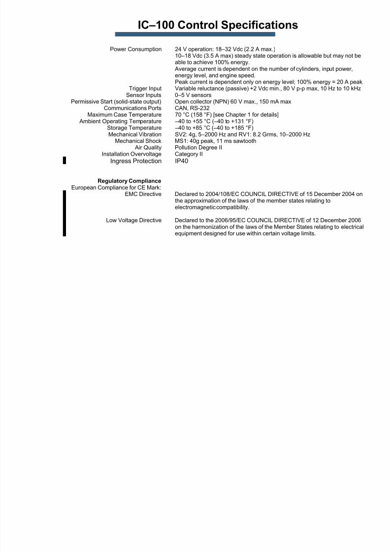
7/24/2019 IC-100 CD Ignation
http://slidepdf.com/reader/full/ic-100-cd-ignation 59/60
IC–100 Control Specifications
Power Consumption 24 V operation: 18–32 Vdc (2.2 A max.)10–18 Vdc (3.5 A max) steady state operation is allowable but may not beable to achieve 100% energy.
Average current is dependent on the number of cylinders, input power,energy level, and engine speed.Peak current is dependent only on energy level; 100% energy = 20 A peak
Trigger Input Variable reluctance (passive) +2 Vdc min., 80 V p-p max, 10 Hz to 10 kHz
Sensor Inputs 0–5 V sensorsPermissive Start (solid-state output) Open collector (NPN) 60 V max., 150 mA maxCommunications Ports CAN, RS-232
Maximum Case Temperature 70 °C (158 °F) [see Chapter 1 for details] Ambient Operating Temperature –40 to +55 °C (–40 to +131 °F)
Storage Temperature –40 to +85 °C (–40 to +185 °F)Mechanical Vibration SV2: 4g, 5–2000 Hz and RV1: 8.2 Grms, 10–2000 Hz
Mechanical Shock MS1: 40g peak, 11 ms sawtooth Air Quality Pollution Degree II
Installation Overvoltage Category II
Ingress Protection IP40
Regulatory ComplianceEuropean Compliance for CE Mark:
EMC Directive Declared to 2004/108/EC COUNCIL DIRECTIVE of 15 December 2004 onthe approximation of the laws of the member states relating toelectromagnetic compatibility.
Low Voltage Directive Declared to the 2006/95/EC COUNCIL DIRECTIVE of 12 December 2006on the harmonization of the laws of the Member States relating to electricalequipment designed for use within certain voltage limits.

7/24/2019 IC-100 CD Ignation
http://slidepdf.com/reader/full/ic-100-cd-ignation 60/60
We appreciate your comments about the content of our publications.
Send comments to: [email protected]
Please reference publication 26205B.
PO Box 1519, Fort Collins CO 80522-1519, USA1000 East Drake Road, Fort Collins CO 80525, USA
Phone +1 (970) 482-5811 Fax +1 (970) 498-3058