ic-f1000 f2000 operatingguide
DESCRIPTION
catalogo radios ICOMTRANSCRIPT
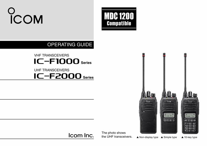
OPERATING GUIDE
The photo shows the UHF transceivers. ▲ Non-display type ▲ Simple type ▲ 10-key type
iF1000 Series
VHF TRANSCEIVERS
iF2000 Series
UHF TRANSCEIVERS
i
We appreciate you choosing Icom for your communication needs.
The MDC 1200 signaling system is built into your IC-F1000/IC-F2000 series transceiver.
READ ALL INSTRUCTIONS carefully and completely before using the transceiver.
SAVE THIS OPERATING GUIDE — This operating guide contains important oper ating instructions for:• IC-F1000, IC-F1000S, and IC-F1000T VHF TRANSCEIVERS• IC-F2000, IC-F2000S, and IC-F2000T UHF TRANSCEIVERS
Icom, Icom Inc. and the Icom logo are registered trademarks of Icom Incor-porated (Japan) in Japan, the United States, the United Kingdom, Germany, France, Spain, Russia and/or other countries.All other products or brands are registered trademarks or trademarks of their respective holders.
IMPORTANT
TABLE OF CONTENTS
ii
IMPORTANT .......................................................................... iTABLE OF CONTENTS ........................................................ ii
1 PANEL DESCRIPTION ................................................1–9 ■ Front, top and side panels ............................................1 ■ Function display ...........................................................3 ■ LED indicator ................................................................4 ■ Programmable function keys ........................................5
2 BASIC OPERATION ................................................10–19 ■ Selecting a channel ....................................................10 ■ Receiving and transmitting .........................................10 ■ Emergency Call ..........................................................12 ■ Lone Worker Emergency Call .....................................13 ■ Man Down Emergency Call ........................................13 ■ Motion Detection Emergency Call ..............................13 ■ User set mode ............................................................14 ■ Setting the Beep function ...........................................16 ■ Setting the Beep level ................................................17 ■ Setting the Ringer level ..............................................18 ■ Setting the microphone gain ......................................19 ■ Setting the squelch level ............................................19
3 MDC 1200 SYSTEM OPERATION ..........................20–22 ■ MDC 1200 system operation ......................................20 ■ Receiving a call ..........................................................20 ■ Transmitting a call .......................................................22
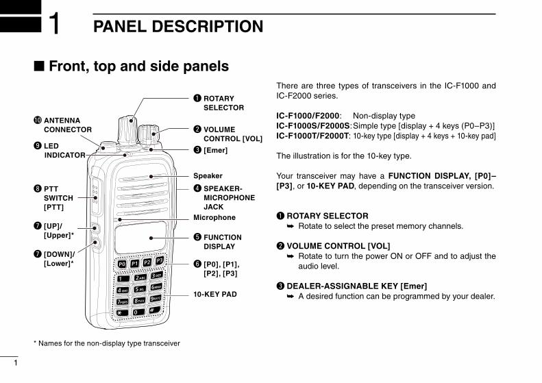
■ Front, top and side panels
* Names for the non-display type transceiver
There are three types of transceivers in the IC-F1000 and IC-F2000 series.
IC-F1000/F2000: Non-display typeIC-F1000S/F2000S: Simple type [display + 4 keys (P0–P3)]IC-F1000T/F2000T: 10-key type [display + 4 keys + 10-key pad]
The illustration is for the 10-key type.
Your transceiver may have a FUNCTION DISPLAY, [P0]–[P3], or 10-KEY PAD, depending on the transceiver version.
q ROTARY SELECTOR Rotate to select the preset memory channels. ➥
w VOLUME CONTROL [VOL] Rotate to turn the power ON or OFF and to adjust the ➥
audio level.
e DEALER-ASSIGNABLE KEY [Emer]A desired function can be programmed by your dealer. ➥
1
1 PANEL DESCRIPTION
w VOLUME CONTROL [VOL]
e [Emer]
Speaker
r SPEAKER- MICROPHONE JACKMicrophone
t FUNCTION DISPLAY
y [P0], [P1], [P2], [P3]
10-KEY PAD
i PTT SWITCH [PTT]
o LED INDICATOR
!0 ANTENNA CONNECTOR
u [UP]/ [Upper]*
u [DOWN]/ [Lower]*
q ROTARY SELECTOR
2
1PANEL DESCRIPTION
12345678910111213141516
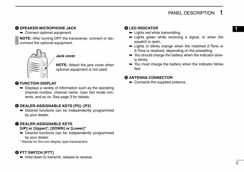
r SPEAKER-MICROPHONE JACKConnect optional equipment. ➥
NOTE: After turning OFF the transceiver, connect or dis-connect the optional equipment.
t FUNCTION DISPLAY Displays a variety of information such as the operating ➥
channel number, channel name, User Set mode con-tents, and so on. See page 3 for details.
y DEALER-ASSIGNABLE KEYS [P0]–[P3] Desired functions can be independently programmed ➥
by your dealer.
u DEALER-ASSIGNABLE KEYS [UP] or [Upper]*, [DOWN] or [Lower]*
Desired functions can be independently programmed ➥
by your dealer. * Names for the non-display type transceivers
i PTT SWITCH [PTT]Hold down to transmit, release to receive. ➥
o LED INDICATORLights red while transmitting. ➥
Lights green while receiving a signal, or when the ➥
squelch is open. Lights or blinks orange when the matched 2-Tone or ➥
5-Tone is received, depending on the presetting. You should charge the battery when the indicator slow- ➥
ly blinks. You must charge the battery when the indicator blinks ➥
fast.
!0 ANTENNA CONNECTORConnects the supplied antenna. ➥
Jack cover
NOTE: Attach the jack cover when optional equipment is not used.
3
1 PANEL DESCRIPTION
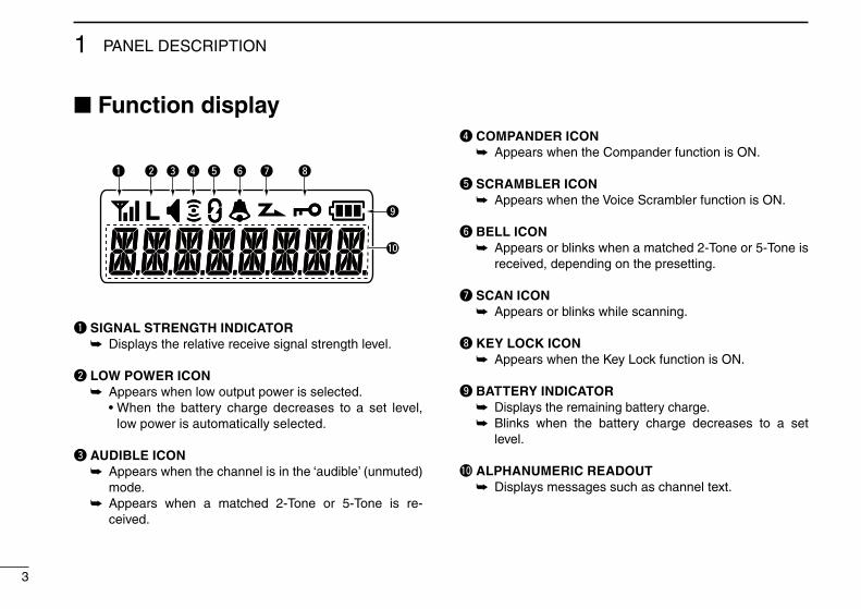
■ Function display
q SIGNAL STRENGTH INDICATOR ➥ Displays the relative receive signal strength level.
w LOW POWER ICON ➥ Appears when low output power is selected.
• When the battery charge decreases to a set level, low power is automatically selected.
e AUDIBLE ICON Appears when the channel is in the ‘audible’ (unmuted) ➥
mode. Appears when a matched 2-Tone or 5-Tone is re- ➥
ceived.
r COMPANDER ICON ➥ Appears when the Compander function is ON.
t SCRAMBLER ICON Appears when the Voice Scrambler function is ON. ➥
y BELL ICON Appears or blinks when a matched 2-Tone or 5-Tone is ➥
received, depending on the presetting.
u SCAN ICON Appears or blinks while scanning. ➥
i KEY LOCK ICONAppears when the Key Lock function is ON. ➥
o BATTERY INDICATOR ➥ Displays the remaining battery charge. Blinks when the battery charge decreases to a set ➥
level.
!0 ALPHANUMERIC READOUT Displays messages such as channel text. ➥
yq iutrew
o
!0
4
1
1
PANEL DESCRIPTION
161514131211109876
45
32
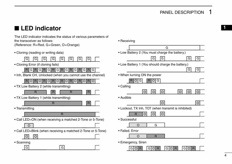
■ LED indicatorThe LED indicator indicates the status of various parameters of the transceiver as follows:(Reference: R=Red, G=Green, O=Orange)
TX Low BATT2
Clone Err
Clone TX/RX
Low BATT1
Low BATT2
Busy
F/S Scan
Cal l LED Bl ink
Cal l LED ON
TX Low BATT1
Clone
G G G G G G G G
R G R G R G R G R G R G R G R G
R O R O R O R O R O R O R O R O
R R R R
R R
R
O
O O
G G
G G
R O G R O G
OOOOOO
O OO O
O OOR
O G
O R
O O O OG R RG G R G R
G G G G
G
• Receiving
• Low Battery 2 (You must charge the battery.)
• Low Battery 1 (You should charge the battery.)
• When turning ON the power
• Calling
• Audible
• Lockout, TX Inh, TOT (when transmit is inhibited)
• Successful
• Failed, Error
• Emergency, Siren
TX Low BATT2
Clone Err
Clone TX/RX
Low BATT1
Low BATT2
Busy
F/S Scan
Cal l LED Bl ink
Cal l LED ON
TX Low BATT1
Clone
G G G G G G G G
R G R G R G R G R G R G R G R G
R O R O R O R O R O R O R O R O
R R R R
R R
R
O
O O
G G
G G
R O G R O G
OOOOOO
O OO O
O OOR
O G
O R
O O O OG R RG G R G R
G G G G
G
• Cloning (reading or writing data)
• Cloning Error (if cloning fails)
• Inh, Blank CH, Unlocked (when you cannot use the channel)
• TX Low Battery 2 (while transmitting)
• TX Low Battery 1 (while transmitting)
• Transmitting
• Call LED=ON (when receiving a matched 2-Tone or 5-Tone)
• Call LED=Blink (when receiving a matched 2-Tone or 5-Tone)
• Scanning
5
1 PANEL DESCRIPTION
■ Programmable function keysFor the Non-display type transceivers, the following functions can be assigned to [Emer], [Upper], and [Lower].
For the Simple type transceivers and the 10-key type trans-ceivers, the following functions can be assigned to [P0], [P1], [P2], [P3], [Emer], [Up], and [Down].
Consult your Icom dealer or system operator for details con-cerning your transceiver’s programming.
CH UP/DOWN As described in the following topics, after pushing a pro- ➥
grammed key, push [CH Up] or [CH Down] to select an option, setting, and so on.
ZONE // only for the Simple type and 10-key type transceivers //
Push this key, then select the desired zone by pushing ➥ [CH Up] or [CH Down].
What is a “zone”?— Certain channels are grouped to-gether and assigned to a zone, according to their intend-ed use. For example, ‘Staff A’ and ‘Staff B’ are assigned to a “Business” zone, and ‘John’ and ‘Cindy’ are assigned to a “Private” zone.
SCAN START/STOP< for the Non-display type transceivers >
Push to start and cancel a scan. ➥
• When a scan is started with the Power ON Scan or Auto-matic scan function, push this key to cancel it. The can-celled scan resumes after a set time period.
< for the Simple type and 10-key type transceivers >Push to start and cancel a scan. ➥
➥ To select the scan group, hold down this key to display scan groups, then push [CH Up] or [CH Down] to select a desired group.
SCAN ADD/DEL (TAG)// only for the Simple type and 10-key type transceivers //
Push to add the operating channel to, or delete it from, the ➥
scan group. 1. Hold down to display the scan group, then push [CH
Up] or [CH Down] to select the desired one. 2. Push to add the channel to, or delete it from, the select-
ed scan group. 3. Hold down to exit the scan list selection mode.
While a scan is paused on a non-priority channel, push this ➥
key to delete the selected channel from the scan group.
Depending on the presetting, the cleared channel may be automatically added to the scan group again after the scan is cancelled.
6
1
1
PANEL DESCRIPTION
PRIORITY A CHANNEL, PRIORITY B CHANNELPush to select the Priority A or Priority B channel. ➥
PRIORITY A CHANNEL (REWRITE),PRIORITY B CHANNEL (REWRITE)
Push to select the Priority A or Priority B channel. ➥
Hold down ➥ [Prio A (Rewrite)] or [Prio B (Rewrite)] to as-sign the operating channel to Priority A or Priority B chan-nel, respectively.
MEMORY CHANNELS 1, 2, 3, 4 Push to directly select memory channel 1, 2, 3 or 4, if pro- ➥
grammed.
MONI // only for the LMR mode // Hold down to cancel the CTCSS (DTCS) or 2-Tone mute. ➥
The transceiver enters “Audible” mode.Push to turn OFF the function. ➥
MONI (Audi) // only for the PMR mode // Hold down to cancel the CTCSS (DTCS) or 5-Tone mute. ➥
The transceiver enters “Audible” mode. Push or hold down to activate one or two functions if pro- ➥
grammed.
LOCK< for the Non-display type transceivers >
Hold down this key to lock all programmable keys except ➥
the followings: [Moni], [Lock], [Emer], [Surveillance], [Siren], [Lone
Worker], and [Shift].< for the Simple type and 10-key type transceivers >
Hold down until “LOCK ON” is displayed to lock all pro- ➥
grammable keys except the followings: [Moni], [Lock], [Emer], [Surveillance], [Siren], [Lone
Worker], and [Shift]. To turn OFF the Key Lock function, hold down until “LOCK ➥
OFF” is displayed.
LONE WORKER< for the Non-display type transceivers >
Hold down to turn ON the Lone Worker Function. ➥
Push to turn OFF the Function. ➥
< for the Simple type and 10-key type transceivers >Push to turn the Lone Worker Function ON or OFF. ➥
• If no operation occurs for a set time period, the trans-ceiver automatically enters the emergency mode.
HIGH/LOW Push to select the transmit output power temporarily or ➥
permanently, depending on the presetting.
7
1 PANEL DESCRIPTION
C.Tone CH ENT // only for the Simple type and 10-key type transceivers //
Push to enter the continuous tone selection mode. Select ➥
the tone frequency or DTCS code using [CH Up] or [CH Down].
TALK AROUNDPush to turn the Talk Around function ON or OFF. ➥
• The Talk Around function equalizes the transmit frequen-cy to the receive frequency for transceiver-to-transceiver communication.
WIDE/NARROW Push to toggle the channel passband width between wide ➥
and narrow.
DTMF AUTODIAL< for the Non-display type transceivers >
Push to transmit the preprogrammed DTMF code. ➥
< for the Simple type and 10-key type transceivers > Push to enter the DTMF number selection mode. Then se- ➥
lect a DTMF number by pushing [CH Up] or [CH Down]. After selecting the DTMF channel, push again to transmit ➥
the selected DTMF code.
RE-DIALPush to transmit the last-transmitted DTMF code. ➥
NOTE: TX memories are cleared after turning OFF the transceiver.
CALL Push to transmit a 2-Tone or 5-Tone in the operating chan- ➥
nel.
CALL A (CODE 1)/CODE B (CODE 2)// only for the LMR model //
Push to transmit a 2-Tone, that is programmed in channel ➥
1 (Code A) or channel 2 (Code B).
CALL A (CODE 30)/CODE B (CODE29)// only for the PMR model //
Push to transmit a 5-Tone as a station code, that is pro- ➥
grammed in channel 30 (Code A) or channel 29 (Code B).
EMERGENCY Hold down during the Emer SW ON timer period to turn ➥
ON the Emergency function. • After the Start or Repeat timer period ends, an Emer-
gency call is automatically transmitted once, or repeat-edly, depending on the presetting.
Hold down during the Emer SW OFF timer period to can- ➥
cel the Emergency function, before transmitting an Emer-gency call.
8
1
1
PANEL DESCRIPTION
SURVEILLANCE< for the Non-display type transceivers >
Hold down to turn ON the Surveillance function. ➥
Push to turn OFF the function. ➥
< for the Simple type and 10-key type transceivers >Push to turn the Surveillance function ON or OFF. ➥
• When this function is ON and a signal is received, a beep does not sound and the LED does not light, even if you push any key.
SIRENHold down to emit a siren sound. ➥
• This function may use for situations other than an emer-gency alert, such as a security alarm.
Turning OFF the transceiver power to stop the siren ➥
sound.
TX CODE ENTER// only for the PMR model (for the Simple type and 10-key type transceivers) //
Push to enter the TX code edit mode (5-Tone). ➥
1. Push [CH Up] or [CH Down] to select the desired digit. You can also enter the digit using the 10-key pad, if it is
on your transceiver. 2. Push [TX Code Enter] to set. The digit to the right will
automatically blink. 3. Repeat step 1 and step 2 to input all editable digits. 4. After editing, push [TX Code Enter] to store the setting
and return to the standby mode.
TX CODE CH SELECT// only for the Simple type and 10-key type transceivers //
Push ➥ [TX Code CH Select] to enter the TX code channel selection mode.
1. Push [CH Up] or [CH Down] to select a desired TX code channel.
2. After selecting, push [TX Code CH Select] to store the setting and return to the standby mode.
// only for the PMR model // During TX code selection mode, hold down to enter the TX ➥
code edit mode (5-Tone). 1. Push [CH Up] or [CH Down] to select the desired digit. You can also enter the digit using the 10-key pad if it is
on your transceiver. 2. Push [TX Code Enter] to set. The digit to the right will
automatically blink. 3. Repeat step 1 and step 2 to input all editable digits. 4. After editing, push [TX Code Enter] to store the set-
tings and return to the standby mode.
TX CODE CH UP/DN// only for the LMR model (for the Simple type and 10-key type transceivers) //
Push to select a preprogrammed TX code channel. ➥
9
1 PANEL DESCRIPTION
TX CODE CH UP/DOWN// only for the PMR model (for the Simple type and 10-key type transceivers) //
Push to select a preprogrammed TX code channel. ➥
Push to select a desired digit in the TX code edit mode. ➥
ID-MR SELECT// only for the PMR model (for the Simple type and 10-key type transceivers) //
Push to recall the received ID code. ➥
• The transceiver can memorize up to 5 codes. Select a desired code by pushing ➥ [CH Up] or [CH Down].Hold down to clear the selected ID code. ➥
SCRAMBLER< for the Non-display type transceivers >
Hold down to turn ON the Voice Scrambler function. ➥
Push to turn OFF the function. ➥
< for the Simple type and 10-key type transceivers >Push to turn the Voice Scrambler function ON or OFF. ➥
COMPANDER< for the Non-display type transceivers >
Hold down to turn ON the Compander function. ➥
Push to turn OFF the function. ➥
< for the Simple type and 10-key type transceivers >Push to turn the Compander function ON or OFF. ➥
• The Compander function reduces noise components from the transmitted audio to provide clear communication.
USER SET MODE// only for the Simple type and 10-key type transceivers //
Hold down to enter the User Set mode. ➥
• While in the User Set mode, push this key to select an item*, and change the value or setting by pushing [CH Up] or [CH Down].
* Selectable items may differ, depending on the presetting. Hold down this key again to exit the User Set mode. ➥
ANNOUNCEPush to turn the Channel Announce function ON or OFF. ➥
NOTE:When the Beep function (p.16) is OFF, the operating chan-nel is not announced, regardless of this setting.
SHIFT// only for the Simple type and 10-key type transceivers // 1. Push to turn ON the Shift mode key functions. “SHIFT ON” is briefly displayed.2. Push another key to activate its secondary function.3. Push [Shift] again to turn OFF the function. The transceiver returns to the Normal mode, then “SHIFT
OFF” is briefly displayed. • The Shift mode enables a programmable function key to
have two functions at the same time.
10
2
1615
1314
1112
109876543
1
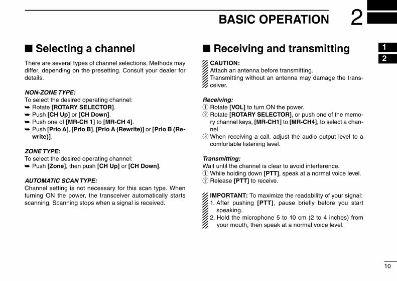
BASIC OPERATION 2■ Selecting a channelThere are several types of channel selections. Methods may differ, depending on the presetting. Consult your dealer for details.
NON-ZONE TYPE:To select the desired operating channel:
Rotate ➥ [ROTARY SELECTOR].Push ➥ [CH Up] or [CH Down].Push one of ➥ [MR-CH 1] to [MR-CH 4]. Push ➥ [Prio A], [Prio B], [Prio A (Rewrite)] or [Prio B (Re-write)].
ZONE TYPE:To select the desired operating channel:
Push ➥ [Zone], then push [CH Up] or [CH Down].
AUTOMATIC SCAN TYPE:Channel setting is not necessary for this scan type. When turning ON the power, the transceiver automatically starts scanning. Scanning stops when a signal is received.
■ Receiving and transmittingCAUTION: Attach an antenna before transmitting. Transmitting without an antenna may damage the trans-ceiver.
Receiving:Rotate q [VOL] to turn ON the power. Rotate w [ROTARY SELECTOR], or push one of the memo-ry channel keys, [MR-CH1] to [MR-CH4], to select a chan-nel. e When receiving a call, adjust the audio output level to a comfortable listening level.
Transmitting:Wait until the channel is clear to avoid interference.
While holding down q [PTT], speak at a normal voice level.Release w [PTT] to receive.
IMPORTANT: To maximize the readability of your signal:1. After pushing [PTT], pause briefly before you start
speaking.2. Hold the microphone 5 to 10 cm (2 to 4 inches) from
your mouth, then speak at a normal voice level.
11
BASIC OPERATION2
11
Transmitting notes DTransmit inhibit function•
The transceiver has several inhibit functions which restrict transmission under the following conditions:
- The channel is busy. However, depending on the presettings, you can transmit
when the call includes an unmatched (or matched) CTC-SS (DTCS) tone.
- The selected channel is a ‘receive only’ channel.
Time-out timer• If continuous transmission exceeds the preprogrammed
time-out timer limit, transmission is cut off.
Penalty timer• The time-out timer cuts off transmission, further transmis-
sion is inhibited for the preprogrammed penalty timer peri-od.
Receiving a Stun, Kill and Revive call DThe dispatcher can send a 2-Tone or 5-Tone that will stun, kill or revive your transceiver.When the Stun call is received, beeps sound*, and you can-not receive or transmit. Receiving a Revive call, or entering a password*, is necessary to operate the transceiver again.
When the Kill call is received, beeps sound*, and the trans-ceiver becomes unusable. Cloning the transceiver is neces-sary to operate the transceiver again, in this case.
* Depending on the presetting. Ask your dealer for details.
12
2
BASIC OPERATION 2
12
2■ Emergency CallWhen pushing [Emergency] for the set time period*, the transceiver transmits an emergency signal once, or repeat-edly, on the specified emergency channel.
The transceiver automatically transmits a repeat emergen-cy signal until it receives an acknowledgement signal, or you turn OFF the transceiver power.When no emergency channel is specified, it transmits the signal on the previously selected channel.
If you want to cancel the emergency call, hold down [Emer-gency] again before transmitting the call.If your transceiver is programmed for Silent operation, you can transmit an Emergency call without the beep sounding and the LED indicator lighting.
IMPORTANT: It is recommended to set an emergency channel individually to provide the certain emergency call operation.
NOTE:Depending on the presetting, the following functions are automatically activated. Ask your dealer for details.
Auto TX function•After an emergency call transmission, the transceiver trans-mits the audio from the microphone for a set time period.*
Auto RX function•After the emergency call transmission, the transceiver stands by in the audible mode for the set time period.*
* Depending on the presetting. Ask your dealer for details.
13
BASIC OPERATION2
■ Lone Worker Emergency CallWhen the Lone Worker function is ON, and if no operation occurs for a set time period*, the transceiver automatical-ly enters the emergency mode. Then the countdown for the emergency call transmission starts.After a set time period* has passed, an emergency call is au-tomatically transmitted once, or repeatedly*.If the user operates the transceiver before the call is trans-mitted, the transceiver exits the emergency mode, and the emergency call is cancelled.
To turn ON the function, see page 6.
■ Man Down Emergency CallThis function may or may not be available, depending on the presetting.When the transceiver has been left in a horizontal position for a set time period*, the transceiver enters the emergency mode, and then a countdown starts.After a set time period* has passed, an emergency call is au-tomatically transmitted once, or repeatedly*. If the transceiver is placed in a vertical position before the first transmission, the transceiver exits the emergency mode, and the emergency call is cancelled.
■ Motion Detection Emergency CallThis function may or may not be available, depending on the presetting.If the acceleration sensor detects the user continuous-ly moves for the set timer period and at the set speed, the transceiver enters the emergency mode, and then the count-down starts.After a set time period* has passed, an emergency call is au-tomatically transmitted once, or repeatedly*. Once the countdown starts, you cannot cancel the emergen-cy call.
* Depending on the presetting. Ask your dealer for details.
14
2
161514131211109876543
1
2BASIC OPERATION
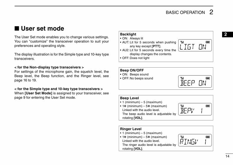
■ User set modeThe User Set mode enables you to change various settings. You can “customize” the transceiver operation to suit your preferences and operating style.
The display illustration is for the Simple type and 10-key type transceivers.
< for the Non-display type transceivers >For settings of the microphone gain, the squelch level, the Beep level, the Beep function, and the Ringer level, see page 16 to 19.
< for the Simple type and 10-key type transceivers >When [User Set Mode] is assigned to your transceiver, see page 9 for entering the User Set mode.
BacklightON: Always lit• AUT: Lit for 5 seconds when pushing •
any key except [PTT].AU2: Lit for 5 seconds every time the •
display changes the contents. OFF: Does not light•
Beep ON/OFFON: Beeps sound• OFF: No beeps sound•
Beep Level1 (minimum) – 5 (maximum)• 1• ❋ (minimum) – 5❋ (maximum)
Linked with the audio level. The beep audio level is adjustable by
rotating [VOL].
Ringer Level1 (minimum) – 5 (maximum)• 1• ❋ (minimum) – 5❋ (maximum)
Linked with the audio level. The ringer audio level is adjustable by
rotating [VOL].
15
BASIC OPERATION2
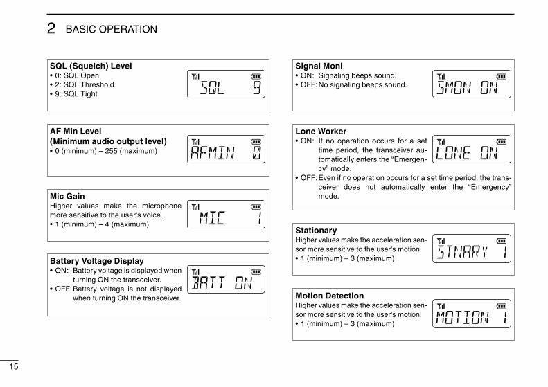
SQL (Squelch) Level0: SQL Open• 2: SQL Threshold• 9: SQL Tight•
AF Min Level(Minimum audio output level)
0 (minimum) – 255 (maximum)•
Mic GainHigher values make the microphone more sensitive to the user's voice.
1 (minimum) – 4 (maximum)•
Battery Voltage DisplayON: • Battery voltage is displayed when
turning ON the transceiver.OFF: • Battery voltage is not displayed
when turning ON the transceiver.
Signal Moni ON: Signaling beeps sound.• OFF: No signaling beeps sound.•
Lone WorkerON: If no operation occurs for a set •
time period, the transceiver au-tomatically enters the “Emergen-cy” mode.
OFF: Even if no operation occurs for a set time period, the trans-• ceiver does not automatically enter the “Emergency” mode.
StationaryHigher values make the acceleration sen-sor more sensitive to the user's motion.
1 (minimum) – 3 (maximum)•
Motion DetectionHigher values make the acceleration sen-sor more sensitive to the user's motion.
1 (minimum) – 3 (maximum)•
16
2
BASIC OPERATION 2
161514131211109876543
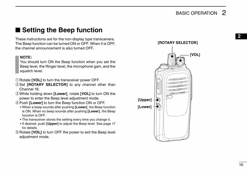
1■ Setting the Beep functionThese instructions are for the non-display type transceivers.The Beep function can be turned ON or OFF. When it is OFF, the channel announcement is also turned OFF.
NOTE:You should turn ON the Beep function when you set the Beep level, the Ringer level, the microphone gain, and the squelch level.
Rotate q [VOL] to turn the transceiver power OFF. Set w [ROTARY SELECTOR] to any channel other than Channel 16. While holding down e [Lower], rotate [VOL] to turn ON the power to enter the Beep level adjustment mode. Push r [Lower] to turn the Beep function ON or OFF.
• When a beep sounds after pushing [Lower], the Beep function is ON. When no beep sounds after pushing [Lower], the Beep function is OFF.
• The transceiver stores the setting every time you change it. • If desired, push [Upper] to adjust the Beep level. See page 17
for details. Rotate t [VOL] to turn OFF the power to exit the Beep level adjustment mode.
[ROTARY SELECTOR]
[VOL]
[Lower]
[Upper]
17
BASIC OPERATION2
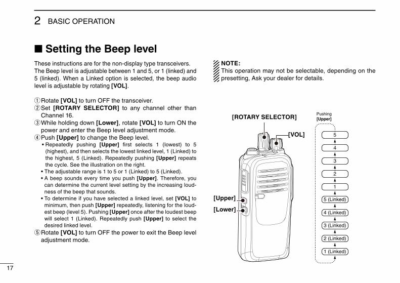
■ Setting the Beep levelThese instructions are for the non-display type transceivers.The Beep level is adjustable between 1 and 5, or 1 (linked) and 5 (linked). When a Linked option is selected, the beep audio level is adjustable by rotating [VOL].
Rotate q [VOL] to turn OFF the transceiver. Set w [ROTARY SELECTOR] to any channel other than Channel 16. While holding down e [Lower], rotate [VOL] to turn ON the power and enter the Beep level adjustment mode. Push r [Upper] to change the Beep level.
• Repeatedly pushing [Upper] first selects 1 (lowest) to 5 (highest), and then selects the lowest linked level, 1 (Linked) to the highest, 5 (Linked). Repeatedly pushing [Upper] repeats the cycle. See the illustration on the right.
• The adjustable range is 1 to 5 or 1 (Linked) to 5 (Linked). • A beep sounds every time you push [Upper]. Therefore, you
can determine the current level setting by the increasing loud-ness of the beep that sounds.
• To determine if you have selected a linked level, set [VOL] to minimum, then push [Upper] repeatedly, listening for the loud-est beep (level 5). Pushing [Upper] once after the loudest beep will select 1 (Linked). Repeatedly push [Upper] to select the desired linked level.
Rotate t [VOL] to turn OFF the power to exit the Beep level adjustment mode.
NOTE:This operation may not be selectable, depending on the presetting, Ask your dealer for details.
[ROTARY SELECTOR]
[VOL]
[Upper]
[Lower]
2
5
4
3
1
5 (Linked)
4 (Linked)
3 (Linked)
2 (Linked)
1 (Linked)
Pushing[Upper]
18
2
161514131211109876543
1
BASIC OPERATION 2
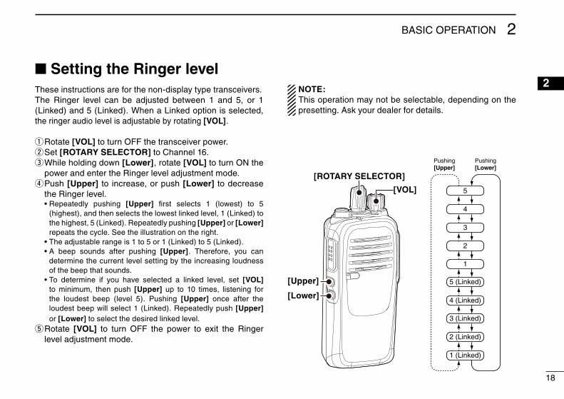
■ Setting the Ringer levelThese instructions are for the non-display type transceivers.The Ringer level can be adjusted between 1 and 5, or 1 (Linked) and 5 (Linked). When a Linked option is selected, the ringer audio level is adjustable by rotating [VOL].
Rotate q [VOL] to turn OFF the transceiver power.Set w [ROTARY SELECTOR] to Channel 16. While holding down e [Lower], rotate [VOL] to turn ON the power and enter the Ringer level adjustment mode. Push r [Upper] to increase, or push [Lower] to decrease the Ringer level.
• Repeatedly pushing [Upper] first selects 1 (lowest) to 5 (highest), and then selects the lowest linked level, 1 (Linked) to the highest, 5 (Linked). Repeatedly pushing [Upper] or [Lower] repeats the cycle. See the illustration on the right.
• The adjustable range is 1 to 5 or 1 (Linked) to 5 (Linked). • A beep sounds after pushing [Upper]. Therefore, you can
determine the current level setting by the increasing loudness of the beep that sounds.
• To determine if you have selected a linked level, set [VOL] to minimum, then push [Upper] up to 10 times, listening for the loudest beep (level 5). Pushing [Upper] once after the loudest beep will select 1 (Linked). Repeatedly push [Upper] or [Lower] to select the desired linked level.
Rotate t [VOL] to turn OFF the power to exit the Ringer level adjustment mode.
NOTE: This operation may not be selectable, depending on the presetting. Ask your dealer for details.
2
5
4
3
1
5 (Linked)
4 (Linked)
3 (Linked)
2 (Linked)
1 (Linked)
Pushing[Lower]
Pushing[Upper]
[ROTARY SELECTOR]
[VOL]
[Upper]
[Lower]
19
BASIC OPERATION2
■ Setting the microphone gainThese instructions are for the non-display type transceivers.Adjust the microphone gain.
Rotate q [VOL] to turn the transceiver power OFF.Set w [ROTARY SELECTOR] to Channel 16. While holding down e [Upper], rotate [VOL] to turn ON the power and enter the microphone gain adjustment mode. Push r [Upper] or to increase, or push [Lower] to decrease the microphone gain.
• The adjustable range is 1 (minimum) to 4 (maximum). • A beep sounds after pushing [Upper] or [Lower]. An error
beep sounds if you try to exceed the adjustable range. Rotate t [VOL] to turn OFF the power to exit the microphone gain adjustment mode.
NOTE: This operation may not be selectable, depending on the presetting. Ask your dealer for details.
■ Setting the squelch levelThese instructions are for the non-display type transceivers.The squelch circuit mutes the received audio signal, de-pending on the signal strength.
Rotate q [VOL] to turn the transceiver power OFF. Set w [ROTARY SELECTOR] to any channel other than Channel 16. While holding down e [Upper], rotate [VOL] to turn ON the power and enter the squelch level adjustment mode. Push r [Upper] to increase the squelch level (tight squelch), or push [Lower] to decrease the squelch level (loose squelch).
• The adjustable range is 0 (loose squelch) to 9 (tight squelch). • A beep sounds after pushing [Upper] or [Lower]. An error
beep sounds if you try to exceed the adjustable range. Rotate t [VOL] to turn OFF the power to exit the squelch level adjustment mode.
NOTE: This operation may not be selectable, depending on the presetting. Ask your dealer for details.
20
23
16151413121110987654
1
3MDC 1200 SYSTEM OPERATION
■ MDC 1200 system operationThe MDC 1200 signaling system enhances your transceiver’s capabilities. You can receive or transmit PTT ID and Emer-gency calls. You can also receive Radio Check, Stun, and Revive calls.
An additional feature of the MDC 1200 system included in Icom transceivers is called aliasing. Each transceiver on the system has a unique ID number. Aliasing is a substitute for this ID number and you can give an alphanumeric name for each station ID. In transmit, you can use this alias to select a transceiver to call. In receive, the alias of the calling station is displayed instead of the ID.
Please confirm that your dealer has set one of the program-mable keys for MDC 1200 system operation. See page 5 for more information about the programmable function keys.
The display illustration is for the Simple type and 10-key type transceivers.
■ Receiving a call
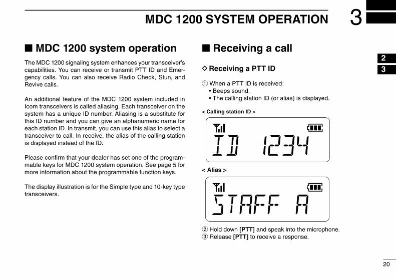
Receiving a PTT ID D
When a PTT ID is received: q
Beeps sound.• The calling station ID (or alias) is displayed.•
< Calling station ID >
< Alias >
w Hold down [PTT] and speak into the microphone.e Release [PTT] to receive a response.
21
MDC 1200 SYSTEM OPERATION3
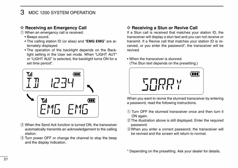
D Receiving an Emergency Callq When an emergency call is received:
Beeps sound.• The calling station ID (or alias) and “• EMG EMG” are al-ternately displayed. The operation of the backlight depends on the Back-• light setting in the User set mode. When “LIGHT AUT” or “LIGHT AU2” is selected, the backlight turns ON for a set time period*.
w When the Send Ack function is turned ON, the transceiver automatically transmits an acknowledgement to the calling station.
e Turn power OFF or change the channel to stop the beep and the display indication.
D Receiving a Stun or Revive CallIf a Stun call is received that matches your station ID, the transceiver will display a stun text and you can not receive or transmit. If a Revive call that matches your station ID is re-ceived, or you enter the password*, the transceiver will be revived.
When the transceiver is stunned.• (The Stun text depends on the presetting.)
When you want to revive the stunned transceiver by entering a password, read the following instructions.
Turn OFF the stunned transceiver once and then turn it q
ON again. The illustration above is still displayed. Enter the required w
password. When you enter a correct password, the transceiver will e
be revived and the screen will return to normal.
* Depending on the presetting. Ask your dealer for details.
22
3
16151413121110987654
21
MDC 1200 SYSTEM OPERATION 3
■ Transmitting a call
Transmitting a PTT ID DYou can notify another person of your station ID or alias.
Push q [PTT] to make a call.Beeps sound, depending on the presetting. w
Your alias or station ID will be transmitted when you push e
[PTT] (at the beginning of transmission) or release it (at the end of transmission), depending on the presetting.
Transmitting an Emergency Call DWhen holding down [Emergency] for a set time period, the emergency signal is transmitted once or repeatedly* on the emergency channel. When no emergency channel is speci-fied, the signal is transmitted on the operating channel.
* When the Repeat Cancel function is ON, the transceiver cancels repeating after receiving an acknowledgement.
When the Repeat Cancel function is OFF, the transceiver repeats calling according to the number of repeat cycles, even after receiv-ing an acknowledgement.
If you want to cancel the emergency call, hold down the key again before transmitting the call.You can transmit an emergency call without a beep emis-sion, and the display indication, depending on the preset-ting. (Silent operation)The transceiver can also be programmed to keep the micro-phone open during an emergency call, allowing monitoring the situation. Ask your dealer for details.
IMPORTANT: It is recommended to set an emergency channel individually to provide the certain emergency call operation.

1-1-32 Kamiminami, Hirano-ku, Osaka 547-0003, JapanA-7122-3EX-q© 2014 Icom Inc.