icme 3gahss: design & cae optimization of …/media/files/autosteel/great designs in...
TRANSCRIPT

GDIS2017
ICME 3GAHSS: DESIGN & CAE OPTIMIZATION OF
LIGHTWEIGHT VEHICLE ASSEMBLY
Eric McCarty
Auto/Steel Partnership
Harry Singh
EDAG, Inc.

#GDIS | #SteelMatters 2
Highlights
INTEGRATED COMPUTATIONAL MATERIALS
ENGINEERING APPROACH TO DEVELOPMENT OF
LIGHTWEIGHT 3GAHSS VEHICLE ASSEMBLY
• Principal Investigator: Dr. Lou Hector Jr. (GM)
• 4+ Year Project - Feb. 1, 2013 – Mar. 31, 2017
• $8.5 Million - $6M DOE, $2.5M Cost Share
• Participants: - 5 universities - 1 national laboratory
- 3 steel companies - 3 automotive OEMs
- 2 engineering firms

#GDIS | #SteelMatters 3
Participants
Universities / National Labs Industry Consortiums
Brown University FCA US LLC Auto/Steel Partnership
Clemson University Ford Motor Company United States Automotive Materials Partnership
Colorado School of Mines General Motors Company
Pacific Northwest National Lab ArcelorMittal
Ohio State University AK Steel Corporation
University of Illinois at Urbana-Champaign Nucor Steel Corporation
EDAG
LSTC

#GDIS | #SteelMatters 4
Steel Strength Ductility Diagram
• Two 3GAHSS steels were developed for model validation and design optimization.
Steel YS (MPa) UTS (MPa) Total Elongation
High Strength, Exceptional Ductility 750 1,200 37%
Exceptional Strength, High Ductility 1,218 1,538 20%

#GDIS | #SteelMatters 5
3GAHSS
• The two 3GAHSS alloys were used for:
Engineering strain
0.00 0.05 0.10 0.15 0.20
Engin
eering s
tress (
MP
a)
0
200
400
600
800
1000
1200
1400
1600
Exp. (Uniaxial tension)
UTS (Exp.)
RVE1 (: 57.4%, ': 25.1%, : 17.5%)
UTS (RVE1)
Phase distribution
Tempered martensite (57.4 %)
Austenite (17.5 %)
Untempered martensite (25.1 %)
Material Model Validation Forming Model Validation Design Optimization
Body Side Assembly (LH &
RH) 46 Stampings
#GDIS | #SteelMatters 6
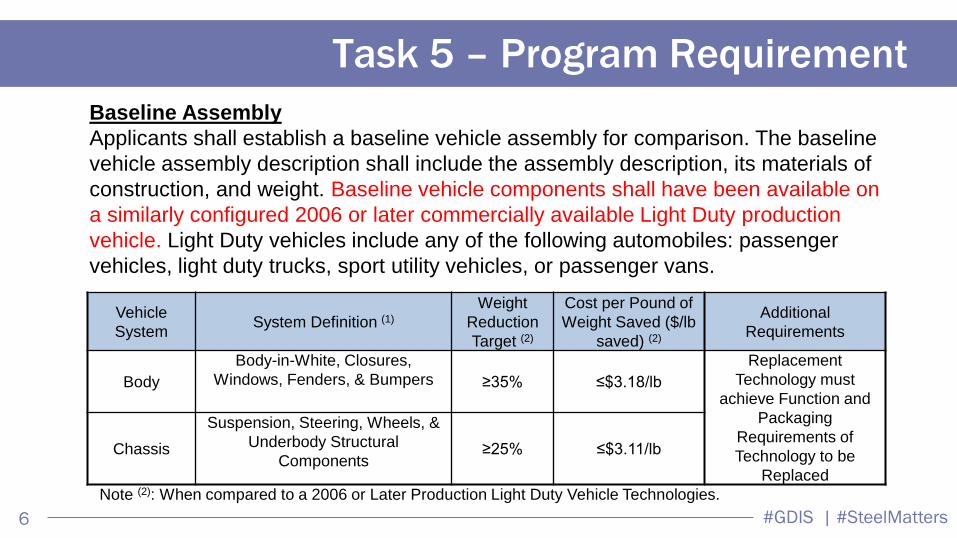
Task 5 – Program Requirement
Vehicle
System System Definition (1)
Weight
Reduction
Target (2)
Cost per Pound of
Weight Saved ($/lb
saved) (2)
Additional
Requirements
Body
Body-in-White, Closures,
Windows, Fenders, & Bumpers ≥35% ≤$3.18/lb
Replacement
Technology must
achieve Function and
Packaging
Requirements of
Technology to be
Replaced
Chassis
Suspension, Steering, Wheels, &
Underbody Structural
Components ≥25% ≤$3.11/lb
Note (2): When compared to a 2006 or Later Production Light Duty Vehicle Technologies.
Baseline Assembly
Applicants shall establish a baseline vehicle assembly for comparison. The baseline
vehicle assembly description shall include the assembly description, its materials of
construction, and weight. Baseline vehicle components shall have been available on
a similarly configured 2006 or later commercially available Light Duty production
vehicle. Light Duty vehicles include any of the following automobiles: passenger
vehicles, light duty trucks, sport utility vehicles, or passenger vans.

#GDIS | #SteelMatters 7
Establish Baseline Assemblies:
1. Select Assemblies
2. Load Cases and Performance Targets (Stiffness, Normal Modes, Crashworthiness)
3. Prepare Detailed FEA Models
4. Cost Model
Design 3GAHSS Assemblies:
1. Design CAD Data
2. Integrate 3GAHSS Assemblies into body structure CAD models
3. Prepare Detailed FEA Models of body structure (LS-DYNA, NASTRAN)
4. Assess Performance and Optimize Design, using 3G (gauge grade and geometry)
optimization, taking advantage of increased formability of 3GAHSS
5. Cost Model
6. Final Report
EDAG - Statement of Work

#GDIS | #SteelMatters 8
Baseline Vehicle & Assembly Body-side
1. Chosen Body Structure: 2008 Mid Size
sedan, CAD data provided by GM
2. Several important joints and major load
paths (important for stiffness and crash load
cases)
3. LWB One Piece Body side inner
4. Several reinforcements in joints and
members
5. LH & RH Body Side Assemblies – Mass
approx 100 kg (30% of BIW)

#GDIS | #SteelMatters 11
LSDYNA Model for Crash Performance
Crash Model System Masses
No Sub System Structure
Mass (kg)
1 BIW 331.6
2 Glass 26.2
3 BIW Adhesives 5.0
4 Door Front Left 28.7
5 Door Front Right 28.7
6 Door Rear Left 26.1
7 Door Rear Right 26.1
8 Rear Suspension 129.7
9 Front Suspension 157.8
10 Powertrain 296.1
11 Steering Column 22.3
12 IP Beam 42.8
13 Front Seat Left 25.0
14 Front Seat Right 23.2
15 Hood 16.2
16 Deck Lid 20.0
17 Fuel tank 74.2
18 Radiator 37.9
19 Rear Bumper/Fascia 17.8
20 Rear Seat System 21.0
21 Occupants 140.0
22 Paint / Latches / Trims /Fenders 93.4
TOTAL 1589.8
Subsystem
represented as
nodal masses
(purple spots) ,
constraint with
interpolation
constraints (blue
webs)
Vehicle COG
X 2827.7
Y 20.4
Z 514.5

#GDIS | #SteelMatters 12
Typical Crash System Model.
All subsystems represented
For the ICME study other sub-systems are represented by
lumped mass only (i.e., sub-system structures are NOT
included in the CAE model). The speed is LOWERED to
reduce the crash energy to achieve body structure intrusions
of similar magnitude of typical Mid-Size Sedan vehicle Pole Impact Speed 20mph
Pole Impact Speed 16.7mph
LSDYNA – Modeling Considerations
For crash load cases, initial velocities are reduced so that the new internal energy is 70% of the total internal
energy using standard regulation velocities. This is because the model is for a BIW only (i.e., not a full vehicle
system model). The 30% energy reduction is a judgment based on experience with prior projects.

#GDIS | #SteelMatters 13
16.7 mph
FMVSS214 – Pole Impact
-30%
Target numbers:
• B-Pillar Velocity & Intrusion
• Roof Rail / Rocker Intrusion at Impact 20 mph

#GDIS | #SteelMatters 14
Baseline Performance Results set as Targets
CAE Load Cases
1. Side Barrier
2. Side Pole
3. Front Impact
4. Rear Impact
5. Roof Crush
1. Body Static Stiffness (Torsion /
Bending)
2. Body Normal Vibration Modes

#GDIS | #SteelMatters 15
Body Side Assembly – design iter-3
Rocker Rear Joint:
Two Stamped Parts
Rocker Front Joint:
Four Stamped Parts
Max. mass saving while meeting crash performance, by
substituting 3GAHSS properties
Min. gauge assumed 0.6 mm
Body inner – two
thickness Laser
Welded Blank

#GDIS | #SteelMatters 16
Body Side Assembly – design iter-6
Replace 2 Parts with a
Single Laser Welded
Blank Stamping
Rocker Front Joint:
Replace 4 parts with 2
Laser Welded Blank
Stampings
Rocker Rear Joint:
Improved joint – iter-4
Rocker Front Joint:
Improved joint – iter-5 LWB – iter-6
Increase joint stiffness by removal of panel joints
Take advantage of increased formability of 3GAHSS

#GDIS | #SteelMatters 17
Iter-3 and Iter-6 Performance
Design Iteration #3 (Gauge
Reduction) Max. mass saving while meeting crash
performance, by substituting 3GAHSS
properties
Min. gauge assumed 0.6 mm
Design Iteration #6 (Combined
parts) Rocker inner combined parts to increase
joint stiffness

#GDIS | #SteelMatters 18
LSOPT Setup for iter-7
Gauge optimization of all parts in
side assembly, sensitivity analysis

#GDIS | #SteelMatters 19
Change in Stiffness per Kg change in Mass

#GDIS | #SteelMatters 20
LS-OPT Setup for iter-8 (from iter-7)
Geometry optimization
#GDIS | #SteelMatters 21
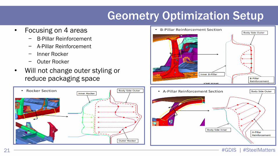
Geometry Optimization Setup • Focusing on 4 areas
− B-Pillar Reinforcement
− A-Pillar Reinforcement
− Inner Rocker
− Outer Rocker
• Will not change outer styling or reduce packaging space
#GDIS | #SteelMatters 23
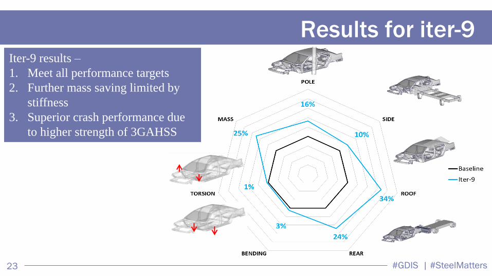
Results for iter-9 Iter-9 results –
1. Meet all performance targets
2. Further mass saving limited by
stiffness
3. Superior crash performance due
to higher strength of 3GAHSS
#GDIS | #SteelMatters 24
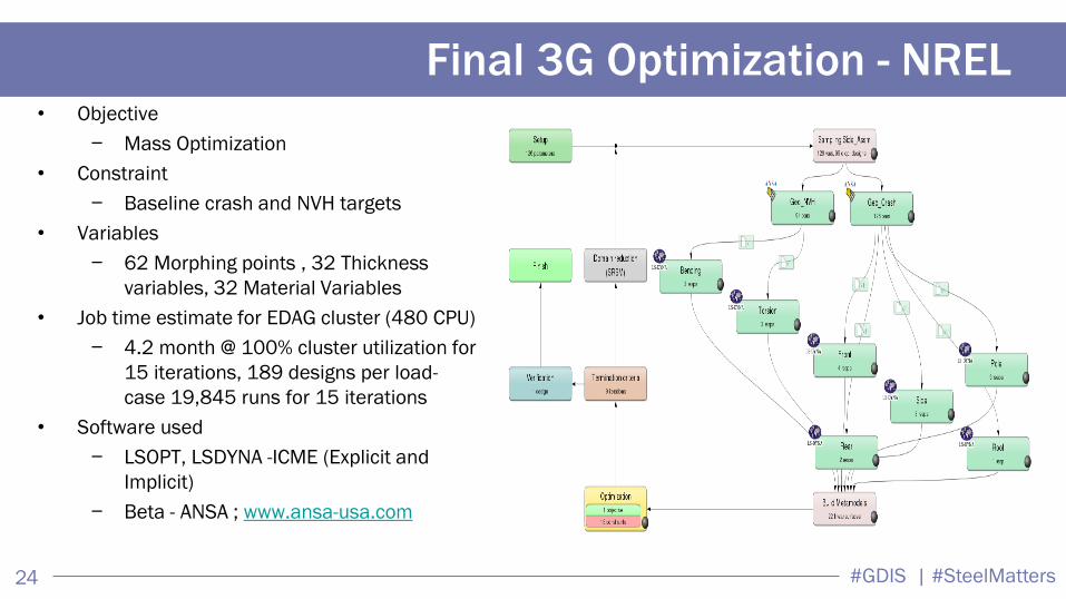
Final 3G Optimization - NREL • Objective
− Mass Optimization
• Constraint
− Baseline crash and NVH targets
• Variables
− 62 Morphing points , 32 Thickness
variables, 32 Material Variables
• Job time estimate for EDAG cluster (480 CPU)
− 4.2 month @ 100% cluster utilization for
15 iterations, 189 designs per load-
case 19,845 runs for 15 iterations
• Software used
− LSOPT, LSDYNA -ICME (Explicit and
Implicit)
− Beta - ANSA ; www.ansa-usa.com

#GDIS | #SteelMatters 25
• CAE 3G Optimization required several ‘scripts’ for
running on the HPC – Peregrine, to transport data
between EDAG & HPC
• Proposed number of cores based on wall clock time
• Option 3 was approved to run on Peregrine HSC at
NREL
NREL HPC Setup
https://www.nrel.gov/esif/labs-hpc.html

#GDIS | #SteelMatters 26
Optimization Variable Setup for 3G Optimization
• 64 parts total
• Thickness
• Min = 0.55mm
• Max = 2.0mm
• Material*
• 10% Mn Steel
• 3% Mn Steel
• Geometry
• Rocker
• B-Pillar
• A-Pillar

#GDIS | #SteelMatters 29
Optimization Performance
315
318
321
324
327
330
333
0 1 2 3 4 5 6 7 8 9 10
BIW
Ma
ss (
kg)
Cycle #
70.8 kg – iter9 (LSOPT
baseline)
67.5 kg – optimized mass
Body side assembly
mass

#GDIS | #SteelMatters 30
Final Optimized Model
Final Model –
1. Design update based on
CAE optimization results,
2. MAT24 replaced with
ICME User Defined
3. Single step forming
4. Manual gauge adjustment
to increase mass saving

#GDIS | #SteelMatters 31
Rocker Profile Animation
Top View Baseline
Optimized
#GDIS | #SteelMatters 34
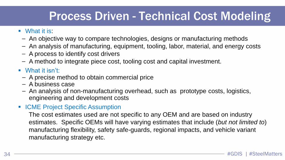
Process Driven - Technical Cost Modeling
What it is:
— An objective way to compare technologies, designs or manufacturing methods
— An analysis of manufacturing, equipment, tooling, labor, material, and energy costs
— A process to identify cost drivers
— A method to integrate piece cost, tooling cost and capital investment.
What it isn’t: — A precise method to obtain commercial price — A business case — An analysis of non-manufacturing overhead, such as prototype costs, logistics,
engineering and development costs
ICME Project Specific Assumption
The cost estimates used are not specific to any OEM and are based on industry
estimates. Specific OEMs will have varying estimates that include (but not limited to)
manufacturing flexibility, safety safe-guards, regional impacts, and vehicle variant
manufacturing strategy etc.

#GDIS | #SteelMatters 35
Baseline - Body Side Assembly LH Sequence
Body Side Asm LH
Assembly layout used to determine assembly
costs based on:
• Number of assembly stations
• Number of spot welding robots
• Complexity of assembly station
• Assembly cycle time
• Foot print of assembly station
• Labor requirements per assembly station

#GDIS | #SteelMatters 36
3GAHSS Cost Estimate per kg Grade HDG Visible
Tailor
Rolled
Coil
Tubes
Straight
as
shipped
Multiwall
Tube
Blank
Min t Max tPremium
($/kg)
Premium
($/kg)
Premium
($/kg)
Premium
($/kg)
Premium
($/kg)
Premium
($/kg)
1 Mild 140/270 0.35 4.60 0.82 0.00 0.06 0.05 0.55 0.25 0.65 1.0 1.0 1.0
2 BH 210/340 0.45 3.40 0.05 0.06 0.10 0.55 0.25 0.65 1.05 0.95 1.05
3 BH 260/370 0.45 2.80 0.05 0.06 0.10 0.55 0.25 0.65 1.05 0.95 1.05
4 BH 280/400 0.45 2.80 0.07 0.06 0.10 0.55 0.30 1.10 1.05 0.95 1.05
5 IF 260/410 0.40 2.30 0.07 0.00 0.10 0.55 0.30 0.70 1.05 0.95 1.05
6 IF 300/420 0.50 2.50 0.10 0.00 0.10 0.55 0.30 1.10 1.05 0.95 1.05
7 HSLA 350/450 0.50 5.00 0.12 0.10 NA 0.55 0.30 1.50 1.05 0.95 1.05
8 HSLA 420/500 0.60 5.00 0.14 0.10 NA 0.55 0.45 1.25 1.10 0.90 1.10
9 HSLA 490/600 0.60 5.00 0.16 0.10 NA 0.55 0.45 1.65 1.10 0.90 1.10
10 HSLA 550/650 0.60 5.00 0.35 0.10 NA 0.55 0.45 1.65 1.10 0.90 1.10
11 HSLA 700/780 2.00 5.00 - - - - - - - - -
12 SF 570/640 2.90 5.00 0.35 0.10 NA NA 0.45 2.05 1.10 0.90 1.10
13 SF 600/780 2.00 5.00 0.35 0.10 NA NA 0.45 2.05 1.10 0.90 1.10
14 TRIP 350/600 0.60 4.00 0.40 0.10 NA NA 0.45 1.25 1.10 0.90 1.10
15 TRIP 400/700 0.60 4.00 0.45 0.10 NA NA 0.45 1.65 1.10 0.90 1.10
16 TRIP 450/800 0.60 2.20 0.50 0.10 NA NA 0.50 1.30 1.15 0.85 1.15
17 TRIP 600/980 0.90 2.00 0.55 0.10 NA NA 0.55 1.35 1.15 0.85 1.15
18 FB 330/450 1.60 5.00 0.20 0.10 NA 0.55 0.30 1.10 1.05 0.95 1.05
19 FB 450/600 1.40 6.00 0.25 0.10 NA 0.55 0.45 1.65 1.10 0.90 1.10
20 DP 300/500 0.50 2.50 0.20 0.10 0.10 0.55 0.45 0.85 1.10 0.90 1.10
21 DP 350/600 0.60 5.00 0.26 0.10 0.10 0.55 0.45 1.25 1.10 0.90 1.10
22 DP 500/800 0.60 4.00 0.31 0.10 NA 0.55 0.50 0.90 1.15 0.85 1.15
23 DP 700/1000 0.60 2.30 0.38 0.10 NA NA 0.55 0.95 1.15 0.85 1.15
24 DP 800/1180 1.00 2.00 - - - - - - - - -
25 DP 1150/1270 0.60 2.00 0.38 0.10 NA NA 0.55 0.95 1.15 0.85 1.15
26 CP 500/800 0.80 4.00 0.31 0.10 NA NA 0.50 1.30 1.15 0.85 1.15
27 CP 600/900 1.00 4.00 0.35 0.10 NA NA 0.52 1.32 1.15 0.85 1.15
28 CP 750/900 1.60 4.00 0.40 0.10 NA NA 0.52 1.32 1.15 0.85 1.15
29 CP 800/1000 0.80 3.00 0.45 0.10 NA NA 0.55 1.35 1.15 0.85 1.15
30 CP 1000/1200 0.80 2.30 0.47 0.10 NA NA 0.60 1.40 1.20 0.80 1.20
31 CP 1050/1470 1.00 2.00 0.47 0.10 NA NA 0.60 1.80 1.20 0.80 1.20
32 MS 950/1200 0.50 3.20 0.47 NA NA NA 0.60 1.00 1.20 0.80 1.20
33 MS 1150/1400 0.50 2.00 0.48 NA NA NA 0.60 1.40 1.20 0.80 1.20
34 TWIP 500/980 0.80 2.00 1.20 0.10 NA NA 0.60 1.80 1.20 0.80 1.20
35 MS 1250/1500 0.50 2.00 0.51 0.10 NA NA 0.65 1.05 1.20 0.80 1.20
36 HF 1050/1500 (22MnB5) 0.60 4.50 0.75 NA NA 0.55 0.65 1.05 1.20 0.80 1.20
37 10Mn 980 0.60 3.00 0.65 0.10 0.60 1.20 0.80 1.20
38 3Mn 1500 0.60 3.00 0.53 0.10 0.60 1.20 0.80 1.20
Reference: Cold Rolled Mild 140/270
US Spot Midwest Market Price (Avg 2010-2014) (Source:
Platts. www.platts.com)
Reject
Rate
Factor
Item # Steel Grade
Ref
Material
Price
($/kg)
Thickness (mm) Tool
Investmt
Factor
Line
Rate
Factor
The average cost over 5 years (2010-2014) per kg of
steel used in the cost model for cold rolled (CR) mild
steel for the US market, published by PLATTS
(www.platts.com).

#GDIS | #SteelMatters 37
3GAHSS Cost Estimate per kg
$0.30
$0.40
$0.50
$0.60
$0.70
400 600 800 1000 1200
TRIP Cost
$0.30
$0.35
$0.40
$0.45
$0.50
$0.55
400 600 800 1000 1200 1400
Complex Phase Cost
Premium
Delta cost
estimate for:
10Mn - $0.65/kg
3Mn - $0.53/kg
Steel Grade UTS MPa
Delta ($/kg)
TRIP 350/600 600 $ 0.40
TRIP 400/700 700 $ 0.45
TRIP 450/800 800 $ 0.50
TRIP 600/980 980 $ 0.55
TRIP X/1200 1200 $ 0.65
Steel Grade UTS MPa
Delta ($/kg)
CP 500/800 600 $ 0.31
CP 600/900 700 $ 0.35
CP 750/900 800 $ 0.40
CP 800/1000 980 $ 0.45
CP 1000/1200 1200 $ 0.47
CP 1050/1470 1470 $ 0.47
CP 1500 1500 $ 0.53

#GDIS | #SteelMatters 38
Vehicle System System Definition (1)
Weight
Reduction
Target (2)
Cost per Pound of
Weight Saved ($/lb
saved) (2)
Additional Requirements
Body Body-in-White, Closures, Windows,
Fenders, & Bumpers ≥35% ≤$3.18/lb Replacement Technology
must achieve Function and
Packaging Requirements of
Technology to be Replaced Chassis Suspension, Steering, Wheels, &
Underbody Structural Components ≥25% ≤$3.11/lb
Note (2): When compared to a 2006 or Later Production Light Duty Vehicle Technologies.
• Baseline Design: 94.6 kg.
• 3GAHSS Design: 66.7 kg.
• Mass savings: 27.9 Kg. (-30%)
• Parts reduced from 46 to 28
• Cost increase $ 20.90
• Cost per Pound of Weight Saved
$0.32 / lb ($0.70 / kg)
$0.32/lb
$1.26/lb
Accomplishments

#GDIS | #SteelMatters 39
Future (2025) Class Average Weights
EDAG Mass Saving Estimates
2015 Ford F-
150
Approximate Fuel
saving due to
Lightweighting
10%

#GDIS | #SteelMatters 40
2015 Ford F-
150
Approximate Fuel
saving due to
Lightweighting
10%
Further development and availability of 3GAHSS will provide an
excellent economic path forward for meeting these goals
Future (2025) Class Average Weights
EDAG Mass Saving Estimates

#GDIS | #SteelMatters 41
Thank you
The material in this presentation was possible with a lot of good feed back
from all participants
Universities / National Labs Industry Consortiums
Brown University FCA US LLC Auto/Steel Partnership
Clemson University Ford Motor Company United States Automotive Materials Partnership
Colorado School of Mines General Motors Company
Pacific Northwest National Lab ArcelorMittal
Ohio State University AK Steel Corporation
University of Illinois at Urbana-Champaign Nucor Steel Corporation
EDAG
LSTC

#GDIS | #SteelMatters 42
Eric McCarty
Auto/Steel Partnership
1 (248) 520 3009
Questions?
Visit EDAG’s web site for more information:
http://www.edag.de/en/edag/stories/cocoon.html
Harry Singh
Director Lightweighting
1 (248) 635-3174
3D Printed EDAG LIGHT COCOON