icomfort m30 smart thermostat...... there is an option in advanced ... if alert code 108 appears on...
TRANSCRIPT

507739-01 10/2017
Supersedes 9/2017
iComfort® M30 Smart ThermostatInstallation and Setup Guide
Disponible en español en www.LennoxPros.com.

2
Tables of ContentsShipping and Packing List ........................... 3Thermostat .................................................... 3
Wall Plate Dimensions (H x W) ............................... 3Compressor Short-Cycle Protection (Compressor Protect) .............................................. 3
Installation Considerations ......................... 4Outdoor Temperature Sensor Installation (Optional) ....................................................... 5Thermostat Installation ............................... 5
New Installation ....................................................... 5Replacement Installation ......................................... 6Common Installation Practices ................................ 6Thermostat Terminal Information ............................ 8System Wiring Diagrams ......................................... 9Connecting Thermostat Wiring ................................ 9Supported Configurations ....................................... 9Install Thermostat to Backplate ............................. 12
Commissioning and Advanced Settings .. 12Commissioning ...................................................... 12Advanced Settings ................................................ 15Advanced Settings Parameter Descriptions .......... 18
Stage Control .............................................. 22Wi-Fi Connection ........................................ 27
Connecting to Visible Home Wi-Fi Access Point ... 28Connecting to Hidden Home Wi-Fi Access Point .. 28Wireless Terminology ............................................ 29
Wireless Connectivity Troubleshooting Tips ... 29Determining Wireless Connection Signal Strength ................................................................. 29
Alert Codes ................................................. 30System Test Modes .................................... 33Save Energy Default ................................... 33Dehumidification Control ........................... 34
Normal and Max .................................................... 34Humiditrol ............................................................. 35Auxiliary Dehumidifier ........................................... 36
Humidification Control ............................... 36Normal and Max .................................................... 37Normal and Max Dew Point Control ...................... 37
Installer Checklist ....................................... 39Index ............................................................ 40

3
WARNINGThis product contains a chemical known to the State of California to cause cancer, birth defects, or other reproductive harm.
Shipping and Packing List
Item Quantity
M30 Thermostat with backplate attached 1
Wall plate 1
Mounting screws (M3.5x25mm self-tapping screws) 2
Wall anchors 2
Warranty sheet 1
Installation & setup guide 1
User guide 1
System Wiring Diagrams Fold-Out Sheet 1
ThermostatUnit Dimensions (H x W x D)
Dimensions: 3-5/16 x 4-5/16 x 7/8 in. (84 x 110 x 22mm)
Wall Plate Dimensions (H x W)
Dimensions: 4-1/2” x 5-3/4” (114 x 146mm)
ComPressor sHort-CyCle ProteCtion (ComPressor ProteCt)
This thermostat is equipped with automatic compressor protection to prevent potential damage due to short cycling or extended power outages.
The non-adjustable short-cycle protection provides a 5-minute delay between heating or cooling cycles to prevent the compressor from being damaged.
NOTE: There is an option in advanced settings that will allow this safety feature to be disabled. By default it is set to ON. Short Cycle protection is disabled during testing of the outdoor unit. It is automatically reset once the test is completed.
WARNINGImproper installation, adjustment, alteration, ser-vice or maintenance can cause property damage, personal injury or loss of life.Installation and service must be performed by a li censed professional HVAC installer (or equivalent) or a service agency.

4
IMPORTANTIn all applications, the M30 thermostat can only be used with all residential units and approved commercial split-system matches, and those which meet the following installation criteria:Installation uses 18 gauge thermostat wire or larger and wire run length DOES NOT EXCEED 300 feet (91 meters).Load from any thermostat connection is 1 AMP or less.
WARNINGAlways turn off power at the main power source by switching the circuit breaker to the OFF position before installing or removing this thermostat.All wiring must conform to local and national building and electrical codes and ordinances.
CAUTIONThis is a 24VAC low-voltage thermostat. Do not install on voltages higher than 30VAC.Do not short (jumper) across terminals on the gas valve or at the system control to test installation.This will damage the thermostat and void the warranty.
Installation Considerations
Before beginning installation, note the type of equipment, number of stages, and any accessories being installed. This thermostat is a 24VAC low-voltage thermostat and requires a common wire to the thermostat to operate.• Shut off all power to system components before
installing thermostat.• Make sure that all wiring conforms to local
and national building and electrical codes and ordinances.
• Never short (jumper) across terminals on the gas valve or at the system control to test installation. This will damage the thermostat and void the warranty.
• Never install thermostat on outside walls or in direct sunlight.

5
Outdoor Temperature Sensor Installation (Optional)
Install the optional (purchase separately) outdoor sensor (X2658) on a northern wall of the home, away from direct sunlight or other heat sources that may affect its sensitivity.
The sensor is required for:• Outdoor temperature displays on the home
screen if enabled• Balance point adjustment and control. The sensor
enables optimal heating equipment operation via programmable balance points.
• Dew point humidity control• Humiditrol EDA operation (required)• Requires 22AWG thermostat wire or larger and
not to exceed 300 feet (91 meters) maximum run.• Connects to To and Tc terminals on thermostat
Connect outdoor sensor to terminals Tc and To on thermostat.
NOTE: If alert code 108 appears on the screen, check your wiring connections to terminals To and Tc on the thermostat. Check resistances using the resistance table provided in the outdoor sensor instruction.
Thermostat Installation
neW installation
The following procedure is for new installation or installing the M30 to a new location in an existing home.1. Unpacked the thermostat and open the case
with a thin-blade screwdriver. Place between wall base and unit and twist to separate unit from base.
2. Select a location for the thermostat about 5 feet (1.5 meters) above the floor in an area with good air circulation at average temperature.
3. Do not install the thermostat where it can be affected by:• Drafts or dead spots behind doors and in
corners.• Building entrances or automatic doors• Heat generating equipment such as kitchen
equipment• Enclose environment unless a remote indoor
sensor is used.• Hot or cold air from ducts.• Radiant heat from sun or appliances.• Concealed pipes and chimneys.• Non-heated (non-cooled) areas such as an
outside wall behind the thermostat.
6
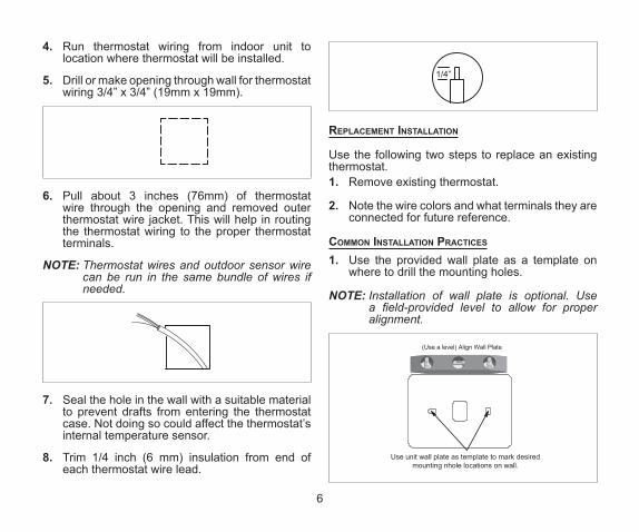
4. Run thermostat wiring from indoor unit to location where thermostat will be installed.
5. Drill or make opening through wall for thermostat wiring 3/4” x 3/4” (19mm x 19mm).
6. Pull about 3 inches (76mm) of thermostat wire through the opening and removed outer thermostat wire jacket. This will help in routing the thermostat wiring to the proper thermostat terminals.
NOTE: Thermostat wires and outdoor sensor wire can be run in the same bundle of wires if needed.
7. Seal the hole in the wall with a suitable material to prevent drafts from entering the thermostat case. Not doing so could affect the thermostat’s internal temperature sensor.
8. Trim 1/4 inch (6 mm) insulation from end of each thermostat wire lead.
1/4”
rePlaCement installation
Use the following two steps to replace an existing thermostat.1. Remove existing thermostat.
2. Note the wire colors and what terminals they are connected for future reference.
Common installation PraCtiCes
1. Use the provided wall plate as a template on where to drill the mounting holes.
NOTE: Installation of wall plate is optional. Use a field-provided level to allow for proper alignment.
(Use a level) Align Wall Plate
Use unit wall plate as template to mark desiredmounting nhole locations on wall.

7
2. Drill 3/16” (5 mm) holes in wall for provided wall anchors. Insert provided wall anchors into drilled holes.
3. Remove back plate from main thermostat assembly using a flat-head screw driver.
4. Route thermostat and outdoor temperature sensor (optional) wiring from wall through center openings on wall plate (use is optional) and back plate.
Wall Plate (optional)
Thermostat Back Plate
Run thermostat wirethrough openings
5. Secure back plate and wall plate (optional) to wall with the two provided mounting screws.
Wall Plate (optional)
Thermostat Back Plate
Screw

8
tHermostat terminal information
Table 1. Terminal Designations
Terminal Purpose
Tc and To Used for connection to an optional outdoor tempera-ture sensor.
ACC1 and ACC2
Default factory software setting for ACC (Accessory) is off. Terminal function setting can be changed by going to settings > advanced settings > terminal settings. Available settings are off, humidify and dehumidify. Connect accessory to terminal ACC2 and change software setting to the applicable type of accessory. Power is supplied by R2 to ACC1 factory jumper.
NOTE: Do not remove the factory installed jumper between ACC1 and R2 terminals unless a secondary 24VAC power source is connected to ACC1.
R2This is the secondary 24VAC power source for ACC (Accessory). The R2 terminal is connected to the ACC1 terminal by factory provided jumper.
D/H
This terminal is for an optional dehumidifier or hu-midifier. Factory default software setting is for dehumidify. Terminal settings can be changed by going to set-tings > advanced settings > terminal settings. Available settings are off, humidify and dehumidi-fy.
NOTE: The user interface refers to the terminal as H/D.
W2 Second-stage heating (non-heat pump) or 4th stage (heat pump).
Y2 Second-stage heating or cooling.
Table 1. Terminal Designations
Terminal Purpose
O/B
Heat pump reversing valve operations. When O (de-fault) is selected under settings > advanced set-tings > terminal settings, the relay is ON during cooling and OFF during heating. When B is selected, the relay is ON during heating and OFF during cooling.
C Common 24VAC
G Fan relay
W1 First-stage heating (non-heat pump or emergency heat) or third-stage heating (heat pump)
Y1 First-stage heating or cooling
R 24VAC power
Table 2. O/B Terminal Relationship States
State O/B Terminal Control
Power ON O terminal : ON (If O terminal selected)B terminal : OFF (If B terminal selected
Heat only or emergency heat mode
O terminal : always OFFB terminal : always ON
Cool mode only
O terminal : always ONB terminal : always OFF

9
Table 2. O/B Terminal Relationship States
State O/B Terminal Control
Heat/Cool mode
During heatingO terminal : OFFB terminal : ONDuring coolingO terminal : ONB terminal : OFFNo DemandThe terminal continues the previous ON / OFF state
Off mode The terminal state continues the state before en-tering off mode
system Wiring Diagrams
For system diagrams, see the included fold-out iComfort® M30 Smart Thermostat System Diagrams sheet.
ConneCting tHermostat Wiring
Use “Table 1. Terminal Designations” on page 8 for connecting the thermostat wiring to the back plate terminals.
If this is a replacement thermostat, connect to terminals as noted when removing the old thermostat. If terminals were different on old thermostat, use “Table 1. Terminal Designations” on page 8 and wiring diagrams provided in the kit.
NOTE: Remember to seal the hole in the wall with a suitable material to prevent drafts from entering the thermostat case. Not doing so could affect the thermostat’s internal temperature sensor.
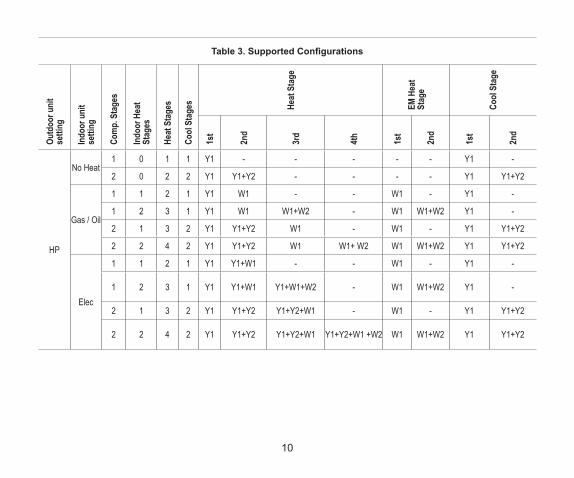
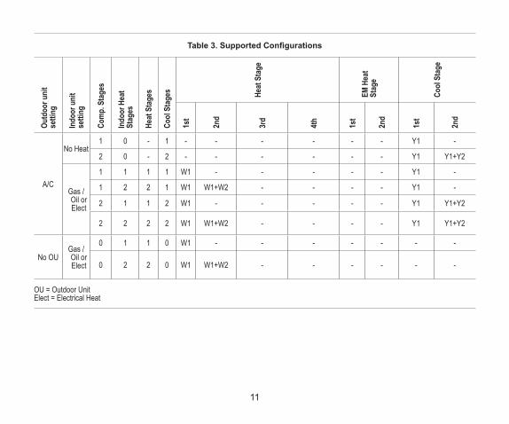
sUPPorteD ConfigUrations
See “Table 3. Supported Configurations” on page 10.
10
Table 3. Supported ConfigurationsOu
tdoo
r uni
t se
tting
Indo
or u
nit
setti
ng
Com
p. S
tage
s
Indo
or H
eat
Stag
es
Heat
Sta
ges
Cool
Sta
ges He
at S
tage
EM H
eat
Stag
e
Cool
Sta
ge
1st
2nd
3rd
4th
1st
2nd
1st
2nd
HP
No Heat1 0 1 1 Y1 - - - - - Y1 -
2 0 2 2 Y1 Y1+Y2 - - - - Y1 Y1+Y2
Gas / Oil
1 1 2 1 Y1 W1 - - W1 - Y1 -
1 2 3 1 Y1 W1 W1+W2 - W1 W1+W2 Y1 -
2 1 3 2 Y1 Y1+Y2 W1 - W1 - Y1 Y1+Y2
2 2 4 2 Y1 Y1+Y2 W1 W1+ W2 W1 W1+W2 Y1 Y1+Y2
Elec
1 1 2 1 Y1 Y1+W1 - - W1 - Y1 -
1 2 3 1 Y1 Y1+W1 Y1+W1+W2 - W1 W1+W2 Y1 -
2 1 3 2 Y1 Y1+Y2 Y1+Y2+W1 - W1 - Y1 Y1+Y2
2 2 4 2 Y1 Y1+Y2 Y1+Y2+W1 Y1+Y2+W1 +W2 W1 W1+W2 Y1 Y1+Y2
11
Table 3. Supported ConfigurationsOu
tdoo
r uni
t se
tting
Indo
or u
nit
setti
ng
Com
p. S
tage
s
Indo
or H
eat
Stag
es
Heat
Sta
ges
Cool
Sta
ges He
at S
tage
EM H
eat
Stag
e
Cool
Sta
ge
1st
2nd
3rd
4th
1st
2nd
1st
2nd
A/C
No Heat1 0 - 1 - - - - - - Y1 -
2 0 - 2 - - - - - - Y1 Y1+Y2
Gas / Oil or Elect
1 1 1 1 W1 - - - - - Y1 -
1 2 2 1 W1 W1+W2 - - - - Y1 -
2 1 1 2 W1 - - - - - Y1 Y1+Y2
2 2 2 2 W1 W1+W2 - - - - Y1 Y1+Y2
No OUGas / Oil or Elect
0 1 1 0 W1 - - - - - - -
0 2 2 0 W1 W1+W2 - - - - - -
OU = Outdoor Unit Elect = Electrical Heat

12
install tHermostat to BaCkPlate
The thermostat assembly simply snaps onto the back plate. Once secure to the back plate apply power to the system. Thermostat should boot up and go into the commissioning process.
Figure 1. Installing Thermostat
If power is applied and the thermostat screen remains off, inspect and verify all wire connections.
Commissioning and Advanced Settings
After power is applied to the thermostat for the first time it displays the Lennox® “splash screen”.
The Installer is then presented with the several Setup Screens to configure the system prior to operation.
Commissioning
“Table 4. Commissioning Screens” on page 13 list all of the screens and parameters that can be configured during the commissioning phase.

13
Table 4. Commissioning Screens
MENU SETTING (default is bold) Notes:
DEALER INFO
Dealer ID Number Enter id Installer can add the dealer number and phone number using the key-board tool.Dealer Phone Number Enter phone
Name, email, website, dealer address (address1, address2, city, state and zip/postal code
GENERAL
Language
English
Français
Español
Country/Region
United States
Canada
Australia
GENERAL Date and Time
Time Adjust the date and time using the set date and set time tools.Date
Time Zone\
Atlantic
Eastern
Central
Mountain
Pacific
Alaska
Hawaii
Samoa
Chamorro (Guam)

14
Table 4. Commissioning Screens
MENU SETTING (default is bold) Notes:
GENERAL Date and TimeDaylight Savings On or Off
Temperature Units °F or °C
TERMINAL SETTINGS (See Terminal Settings on page 17)
SYSTEM SETUP (See System Setup on page 15)
OUTDOOR SENSOR (See Outdoor Sensor on page 16)
HUMIDITY Humidity ControlOff
Dehumidify
NOTIFICATIONS (Reminders)
Replace Filter 1 Disabled
Adjustable 3, 6, 12, 24 months or custom date, can be set to calendar time or run-time.Touch custom to access the Set date Tool screen to input custom date settings.
Replace Filter 2 Disabled
Replace UV Bulb Disabled
Replace Humidifier Pad Disabled
PureAir Maintenance Disabled
Maintenance Reminder Disabled

15
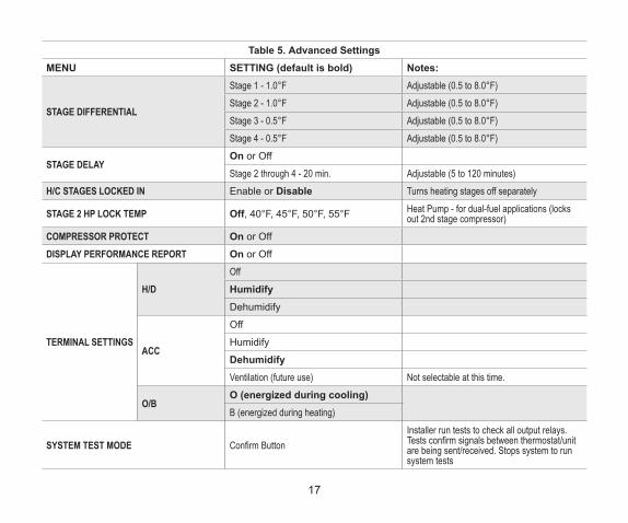
aDvanCeD settings
“Table 5. Advanced Settings” on page 15 list the menu options and parameters that can be set under the Advance Settings menu option.
Table 5. Advanced SettingsMENU SETTING (default is bold) Notes:
SYSTEM SETUP
Outdoor Unit Type
Not Installed1 Stage A/C Unit2 Stage A/C Unit1 Stage HP Unit2 Stage HP Unit
Outdoor Unit Capacity - 36 kBtu Adjustable 18 to 60 kBu
Outdoor Unit 1st Stage Capac (capacity) Adjustable 30 to 100%(This setting is only available if outdoor unit is 2-stage.)
Indoor Unit Type
Not Installed1 Stage Electric2 Stage Electric1 Stage Oil2 Stage Oil1 Stage Gas2 Stage Gas

16
Table 5. Advanced SettingsMENU SETTING (default is bold) Notes:
SYSTEM SETUP
HumidifierNot Installed
These options only appear under System Setup if the H/D and ACC terminals have been enabled for the specific type of accessory. Go to Terminal Settings to enabled attached accessory for the specific terminal being used.
Humidification
Dehumidifier
Not InstalledHumiditrol - MinHumiditrol - MidHumiditrol - MaxAuxiliary Dehumidifier
OUTDOOR SENSOR Yes or No Required for high and low balance points option.
RESIDUAL COOL 0, 30, 60, 90, 120 seconds, -300 (5 min delayed)
BALANCE POINT Disabled or Enabled
When enabled:Low Balance Point: 25°F (-20 to 72°F)High Balance Point: 50°F(-17 to 75°F)
TEMPERATURE CONTROL MODE Normal and ComfortWALL INSULATION Poor, Average and GoodDEADBAND 3°F Adjustable (3 to 8°F)SMOOTH SETBACK RECOVERY Enabled or Disabled
OFFSET Temperature Offset - 0°F Adjustable (-5 to 5°F)
Humidity Offset - 0% Adjustable (-10 to 10%)
17
Table 5. Advanced SettingsMENU SETTING (default is bold) Notes:
STAGE DIFFERENTIAL
Stage 1 - 1.0°F Adjustable (0.5 to 8.0°F)Stage 2 - 1.0°F Adjustable (0.5 to 8.0°F)Stage 3 - 0.5°F Adjustable (0.5 to 8.0°F)Stage 4 - 0.5°F Adjustable (0.5 to 8.0°F)
STAGE DELAYOn or Off
Stage 2 through 4 - 20 min. Adjustable (5 to 120 minutes)H/C STAGES LOCKED IN Enable or Disable Turns heating stages off separately
STAGE 2 HP LOCK TEMP Off, 40°F, 45°F, 50°F, 55°F Heat Pump - for dual-fuel applications (locks out 2nd stage compressor)
COMPRESSOR PROTECT On or Off
DISPLAY PERFORMANCE REPORT On or Off
TERMINAL SETTINGS
H/DOffHumidifyDehumidify
ACC
Off
Humidify
DehumidifyVentilation (future use) Not selectable at this time.
O/BO (energized during cooling)B (energized during heating)
SYSTEM TEST MODE Confirm ButtonInstaller run tests to check all output relays. Tests confirm signals between thermostat/unit are being sent/received. Stops system to run system tests

18
Table 5. Advanced SettingsMENU SETTING (default is bold) Notes:RESET SETTING Confirm Button Resets all parameters to factory settingsRESTART Confirm Button Reboot the thermostat.
aDvanCeD settings Parameter DesCriPtions
Table 6. Parameter Descriptions
Parameter Name Definition
Smooth Setback Recovery (SSR)
SSR is an algorithm designed to smoothly” reach a occupied program schedule setpoint. The algorithm looks 2 hours ahead for the occupied program schedule period’s setpoint. If the occupied setpoint requires the system to turn on (present temperature below the heat setpoint or above the cool setpoint), then SSR will calculate a new setpoint. Once initiated, SSR monitors the change in room temperature and calculates a new setpoint ev-ery 30 seconds. Then SSR provides this new setpoint for the heating and cooling algorithms; the new setpoint will be displayed on the User Interface.SSR Rules:• SSR is enabled when both Smooth Setback Recovery” is set to enabled
(default) and the program schedule is turned on.• SSR does NOT turn off stage delay timers.• SSR will NOT change the dead band between heating and cooling modes.• SSR will not overshoot the target set point.• SSR will reset if the user updates the program schedule during the active
SSR period. Smooth Setback Recovery - default is enabled .
NOTE: SSR aims to bring the sensor temperature (room temperature) to the value of the next active set point at the exact time the next active set point is associated with. This means that conditioning to reach the next active set point starts before the currently active set point period expires.
OffsetThis is a feature that lets you adjust the room temperature reading +/- 5°F. This helps if your thermostat is in a slightly warm or cold spot, or if the room temperature does not match your old thermostat. The other option setting in our thermostat is humidity offset which is basically the same as temperature, but works on a humidity percentage instead.

19
Table 6. Parameter Descriptions
Parameter Name Definition
Stage Differential
There are four options for stage differential:• 1st Stage Differential: The default is 1.0°F. The first stage differential is the difference between
the equipment activation and deactivation temperatures. The first stage differential is used in all models. It can be programmed between 0.5 and 8.0°F in 0.5°F steps.
• 2nd Stage Differential: The default is determined by the system setup. The second stage differential is used in the multi-stage model only. The second stage differential is the difference in temperature between the second stage activation and the first stage activation. It can be programmed between 0.5 and 8.0°F in 0.5°F steps. If system has only 1st stage equipment, this item is hidden from installer screen.
• 3rd Stage Differential: This setting is used with the multi-stage model, in heat pump applications only. The default is determined by the system setup. The third stage differential is the difference in temperature between the third stage activation and the second stage activation. It can be programmed between 0.5 and 8.0°F in 0.5°F steps. If system has no more than three stages equipment, this item is hidden from installer screen.
• 4th Stage Differential: This setting is used with the multi-stage model, in heat pump applications only. The default is determined by the system setup. The fourth stage differential is the difference in temperature between the fourth stage activation and the third stage activation. It can be programmed between 0.5 and 8.0°F in 0.5°F steps. If system does not have fourth stage equipment, this item is hidden from installer screen.

20
Table 6. Parameter Descriptions
Parameter Name Definition
Stage Delays
There are four settings for this option:• Stage Delay Timer: The user shall be able to select ON (default) or OFF for stage delay timers.
When OFF is selected all STG DELAYS timers (STG 2 DELAY, STG 3 DELAY, STG 4 DELAY) are disabled. This means that the stages are changed based on the temperature and not the timer delays. When ON is selected all STG DELAYS timers are enabled and set to their default values (20min). If system has only first stage equipment, this item is hidden from installer screen.
• 2nd Stage Delays: The Stage Delay option is enabled when ON is selected from STG Delay Timers. The second stage delay is used in the multi-stage model only. The default is 20 minutes. If the first stage fails to advance the ambient temperature toward the setpoint by 1.0°F during each consecutive programmed time delay, then the second stage is activated until demand is satisfied. It can be programmed from 5 to 120 minutes in 5-minute steps. If system has only first stage equipment, this item is hidden from installer screen.
• 3rd Stage Delays: The Stage Delay option is enabled when ON is selected from STG Delay Timers. This setting is used with the multi-stage model, in heat pump applications only. The default is 20 minutes. If the second stage fails to advance the ambient temperature toward the setpoint by 1.0°F during each consecutive programmed time delay, then the third stage is activated until demand is satisfied. It can be programmed from 5 to 120 minutes in 5-minute steps. If the system has no more than three stages, this item is hidden from the installer screen.
• 4th Stage Delays: The Stage Delay option is enabled when ON is selected from STG Delay Timers. This setting is used with the multistage model, in heat pump applications only. The default is 20 minutes. If the third stage fails to advance the ambient temperature toward the set point by 1.0°F during each consecutive programmed time delay, then the fourth stage is activated until demand is satisfied. It can be programmed from 5 to 120 minutes in 5-minute increments. If the system does not have a fourth stage, this item is hidden from installer screen. If temperature is stuck at a value lower than the set point and multiple stages have been turned on because of the delay timers expired (not because of the temperature), all these stages shall stay on until the required temperature (set point + 0.5) is reached.
H/C STGS Locked InThe user shall be able to select disable or enable for H/C STGS LOCKED IN mode. In disable, mode different stages of heat or cool are turned off separately. In enable mode, different stages of heat or cool are turned off together.
Stage 2 HP Lock TempThe User shall be able to select the STG 2 HP lock temp from 40F, 45F, 50F, 55F or OFF. The value is used in dual fuel algorithm to lock the second stage of compressor .The default is OFF which means it is disabled and is not used in dual fuel algorithm. If system has only 1st stage equipment, this item is hidden from installer screen. For more information see “Stage 2 HP Lock Temp” on page 28.

21
Table 6. Parameter Descriptions
Parameter Name Definition
Feels Like This feature will display the home temperature based on a combination of inputs. Feels Like uses outdoor temperature, indoor temperature, and indoor humidity to determine the “feels like” condition of the home.
Wider Set Point Range By default your thermostat operates within a range of 60-90°F. Enabling this options changes the range to 44-99°F.
Heating Mode: Normal or Comfort
Options are Normal and Comfort. Default is Normal. When changing to Comfort Mode, several parameters are automatically modified for optimal system operations. The changed parameters are listed on the screen when set to Comfort.• Normal - This setting cools the home to the desired temperature setting. Once second-stage is activated
by timer or differential, it will not stage down to first-stage until the next heating cycle demand.• Comfort - This is when the system could automatically stage up
or down based on the current load demand.
Smart Away This setting when enabled controls the temperature in the home when no one is home. For this to function, the Lennox Mobile app needs to be installed on a mobile device.
Low Balance Point
(Multistage Heat Pump Model only) -The default is 25°F. This option will only be available if an outdoor sensor is installed. If the outside temperature is below the programmed Low Balance Point, then the compressor stage operation is disallowed. This protects the compressor from operation and damage in cold outdoor tem-peratures. Also, if the heat pump is not effective at a low outdoor temperature, then it is more comfortable and efficient to go directly to the second stage. Low Balance Point can be disable in this screen. When this is enable, the options are from –40°F to (the High Balance Point temperature -2) in 1.0°F steps.
High Balance Point
The default is 50°F. This option is only available if an outdoor sensor is installed. If the outside temperature is above the High Balance point, then the auxiliary heat stage is disallowed. This prevents the more expensive auxiliary heat stage from operating, and forces the more efficient heat pump to satisfy the demand. High Balance Point can be disable in this screen. When this is enable, the high balance point range is from (the low balance point + 2) up to 75°F.
DeadbandThe deadband setting is the minimum difference between the cooling and heating setpoints. This setting is used in auto-changeover to ensure smooth equipment operation. It also allows for flexibility of Humiditrol oper-ation. The default deadband is 3 and the deadband is adjustable from 3 to 9°F degrees.

22
Table 6. Parameter Descriptions
Parameter Name Definition
Offset
There are two options for offset which are:• Temperature offset can be used to offset the displayed space temperature by up to +/- 5 degrees.
The default temperature offset is zero. This offset also applies to the control temperature. • Humidity offset can be used to offset the displayed room humidity
by up to +/- 10%, the default offset is 0.
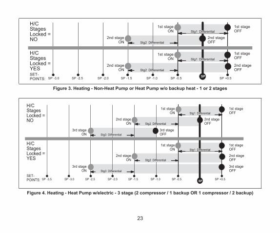
Stage Control• The following figures list typical configurations.
H/CStagesLocked =YES
H/CStagesLocked =NO
POINTS:
2nd stageON
2nd stageOFF
1st stageON
1st stageOFF
2nd stageON
2nd stageOFF
1st stageON
1st stageOFF
SP -1.5 SP -1.0 SP -0.5 SP SP +1.5SP +1.0 0.2+ PS5.0+ PS
Stg1 Differential
Stg2 Differential
Stg2 Differential
Stg1 Differential
Figure 2. Cooling - 1 or 2 stages
23
H/CStagesLocked =YES
H/CStagesLocked =NO
1st stageON
2nd stageON
1st stageON
2nd stageON
2nd stageOFF
1st stageOFF
1st stageOFF
2nd stageOFF
SP -1.5 SP -1.0 SP -0.5 SP SP +0.5SP -2.0
Stg1 Differential
Stg2 Differential
SP -2.5SP -3.0
Stg1 Differential
Stg2 Differential
POINTS:
Figure 3. Heating - Non-Heat Pump or Heat Pump w/o backup heat - 1 or 2 stages
H/CStagesLocked =NO
H/CStagesLocked =YES
POINTS:
3rd stageON
1st stageON
2nd stageON
3rd stageON
1st stageON
2nd stageON
2nd stageOFF
3rd stageOFF
1st stageOFF
1st stageOFF
2nd stageOFF
3rd stageOFF
SP -1.5 SP -1.0 SP -0.5 SP SP +0.5SP -2.0
Stg1 Differential
Stg3 Differential
Stg2 Differential
SP -2.5SP -3.0SP -3.5
Stg1 Differential
Stg3 Differential
Stg2 Differential
Figure 4. Heating - Heat Pump w/electric - 3 stage (2 compressor / 1 backup OR 1 compressor / 2 backup)

24
H/CStagesLocked =YES
H/CStagesLocked =NO
3rd stageON
1st stageON
2nd stageON
4th stageON
3rd stageON
1st stageON
2nd stageON
4th stageON
2nd stageOFF
3rd stageOFF
4th stageOFF
1st stageOFF
Stg4 Differential
1st stageOFF
2nd stageOFF
3rd stageOFF
4th stageOFF
POINTS: SP -1.5 SP -1.0 SP -0.5 SP SP +0.5SP -2.0
Stg1 Differential
Stg3 Differential
Stg2 Differential
SP -2.5SP -3.0SP -3.5
Stg1 Differential
Stg3 Differential
Stg2 Differential
Stg4 Differential
Figure 5. Heating - Heat Pump w/electric - 4 stage (2 compressor / 2 backup)
H/CStagesLocked =NO orYES
2nd stageON
1st stageON
2nd stageOFF
1st stageOFF
SP -1.5 SP -1.0 SP -0.5SP
SP +0.5SP -2.0
Stg1 Differential
SP -2.5SP -3.0
Stg2 Differential
POINTS:
Figure 6. Heating - dual fuel - 2 stage (1 compressor / 1 backup)

25
H/CStagesLocked =NO
H/CStagesLocked =YES
POINTS:
3rd stageON
1st stageON
2nd stageON
3rd stageON
1st stageON
2nd stageON
2nd stageOFF
3rd stageOFF
1st stageOFF
1st stageOFF
2nd stageOFF
3rd stageOFF
SP -1.5 SP -1.0 SP -0.5 SP SP +0.5SP -2.0
Stg1 Differential
Stg3 Differential
Stg2 Differential
SP -2.5SP -3.0SP -3.5
Stg1 Differential
Stg3 Diff.
Stg2 Differential
Figure 7. Heating - dual fuel - 3 stage (1 compressor / 2 backup)
H/CStagesLocked =NO
H/CStagesLocked =YES
POINTS:
3rd stageON
1st stageON
2nd stageON
3rd stageON
1st stageON
2nd stageON
2nd stageOFF
3rd stageOFF
1st stageOFF
1st stageOFF
2nd stageOFF
3rd stageOFF
SP -1.5 SP -1.0 SP -0.5 SP SP +0.5SP -2.0
Stg1 Differential
Stg3 Differential
Stg2 Differential
SP -2.5SP -3.0SP -3.5
Stg1 Differential
Stg3 Differential
Stg2 Differential
Figure 8. Heating - dual fuel - 3 stage (2 compressor / 1 backup)

26
Stg4 Diff.
H/CStagesLocked =YES
H/CStagesLocked =NO
3rd stageON
1st stageON
2nd stageON
4th stageON
3rd stageON
1st stageON
2nd stageON
4th stageON
2nd stageOFF
3rd stageOFF
4th stageOFF
1st stageOFF
Stg4 Differential
1st stageOFF
2nd stageOFF
3rd stageOFF
4th stageOFF
POINTS: SP -1.5 SP -1.0 SP -0.5 SP SP +0.5SP -2.0
Stg1 Differential
Stg3 Differential
Stg2 Differential
SP -2.5SP -3.0SP -3.5
Stg1 Differential
Stg3 Differential
Stg2 Differential
Figure 9. Heating - dual fuel - 4 stage (2 compressor / 2 backup)

27
Wi-Fi Connection
Wireless networks supported by this system are:• 802.11b is 2.4Ghz band (max 11 Mbit/s) • 802.11g is 2.4Ghz band (max 54 Mbit/s)• 802.11n is 2.4Ghz band (max 130 Mbit/s)
This is for connecting the thermostat to a secure home wireless network.
NOTE: A router with Bonjour capabilities is required for this function. Check the router functions if the thermostat does not connect. Apple Bonjour® is an implementation of zero-configuration networking (Zeroconf), a group of technologies that includes service discovery, address assignment, and host name resolution.
NOTE: Never use a home guest account and never use an open router connection (non-secure).
NOTE: Always use a secure connection physically located in the home where the thermostat is located.
NOTE: If thermostat will not connect to the home router, then try using a hot spot to check thermostat Wi-Fi connectivity. A Wi-Fi extender may be required or move the router closer to thermostat for connection.
1. Touch the Menu icon in the upper right-hand corner of the display.
2. Touch the settings option on the menu.

28
3. If Wi-Fi is set to disabled, touch the > icon to enabled. The Wi-Fi screen will appear where you can toggle it to ON.
ConneCting to visiBle Home Wi-fi aCCess Point
1. Touch Wi-Fi network. This will display a list of visible Wi-Fi networks within range of the thermostat.
2. Select the homeowner network and type in the password. Touch join to continue.
NOTE: The thermostat can connect to a home wireless router that uses up to 32 characters in the access point name (visible or hidden).
NOTE: If you wish to see the characters you are typing, check show password. The thermostat will support up to a 63 character password. The password cannot contain the % or # symbols.
3. If joining the network was successful, the access point name will appear next to Wi-Fi networks.
ConneCting to HiDDen Home Wi-fi aCCess Point
1. Touch Wi-Fi network. Scroll down to others.
2. Enter new network information. You will need the name of the access point and the type of security being used. Select Security. Options are: none, WEP, WPA and WPA2. If your home Wi-Fi connection is unsecured, then Wi-FI security must be enabled using WEP, WPA or WPA2 via the router before proceeding. Consult your router documentation on how to enable Wi-Fi security.
3. Enter the password.
4. Touch join to complete.
5. If joining the hidden network was successful, the access point name will appear next to wi-fi networks.
Whether connecting to a visible or hidden network, if successful, a check mark will appear above both the router and Internet icons.
HOME WI-FIROUTER
INTERNETACCESS
SERVERCONNECTION
M30THERMOSTAT

29
Wireless terminology
The following terminology is used:• Received Signal Strength Indication (RSSI). This
indicates the signal strength of the Wi-Fi router being received by the scanning device (i.e., smart phone). So the higher the RSSI number (or less negative in some devices), the stronger the signal.
• Internet Protocol Address (IP address). This is an address assigned by your home router for each network device (e.g., computer, printer, thermostat).
Wireless ConneCtivity troUBlesHooting tiPs
Locate the thermostat and router away from other devices that could possibility interfere with wireless communications. Some examples of other devices that could interfere are:• Microwave ovens• Wireless cameras• Portable phones and bases• Baby monitors• Wireless speakers• Bluetooth devices• Garage door openers• Neighbor’s wireless devices
To eliminate a possible source of interference, temporally disable any nearby 2.4Ghz band devices in the home and see if Wi-Fi performance has improved.
Determining Wireless ConneCtion signal strengtH
The ideal signal strength range for the thermostat is -1 to -69 Received Signal Strength Indication (RSSI). The signal strength can be viewed from the thermostat interface.1. Press NETWORK SETTINGS; This screen
shows a graphical view of buttons representing OPEN and SECURE wireless networks, along with button for adding a network.
2. Select the access point that has already been established and connected.
3. When selecting the info icon, a screen will appear which will display an option to forget the network and IP address assigned to the thermostat by your router, sub-net mask, router, DNS and RSSI.
4. If the RSSI signal strength is anywhere between -9 to -69, then the signal strength is sufficient. If outside this range, then either relocate the router closer to the thermostat, add a repeater, or move the thermostat. Adjusting antenna on router may resolve the issue.
Home Network . . . . . . . . . . . . . . . . . . . . . . . .
IP address 192.168.1.4subnet mask 255.255.255.0routerDNSMAC address
iforget this network
192.168.1.1192.168.1.1
00:23:a7:b7:a1:70

30
Alert Codes
Table 7. Alert Codes and Reminders
Alert Code
Priority Condition Display Message Condition System Action Clear/Recovery
18 Minor Low Ambient HP Heat Lockout
The outside temperature is below the level where the heat pump is programmed to heat the home.
When the thermostat is in heat mode and a heat demand exists, if the temperature measured by outdoor sensor is below the low balance point, the heat pump is turned off and only the electric heat or gas/oil heat is used.
NOTE: This alert message is not displayed.
If the temperature measured by outdoor sensor is rises above low the balance point, then any available heat source (heat pump, electric heat or gas/oil heat) can be used.
19 MinorHigh Ambient Auxiliary Heat Lockout
The outside temperature is higher than the level where the furnace or electric heat is programmed to work.
When the thermostat is in heat mode and a heat demand exists, if the temperature measured by outdoor sensor is above the high balance point, the electric heat or gas/oil heat is turned off and only the heat pump is used.
NOTE: This alert message is not displayed.
If the temperature measured by outdoor sensor drops below the high balance point, then any available heat source (heat pump, electric heat or gas/oil heat) can be used.
29 Critical Over Temperature Protection
Indoor temperature that is higher than 99ºF.
• All stages of heat and cool are turned off by safety relay.
• Heating and cooling operation is not allowed.
• This error is displayed in notification screen.
If room temperature goes less then 99°F, it will start working again.
30 Moderate Low Temperature Protection
Indoor temperature that is lower than 40ºF.
If room temperature goes more then 40°F, it will start working again.

31
Table 7. Alert Codes and Reminders
Alert Code
Priority Condition Display Message Condition System Action Clear/Recovery
180 Critical Outdoor Temperature Sensor Problem
Outdoor sensor reads out of range (-50ºF to 180ºF)
• Operation will be performed. (Weather information is not used)
• Thermostat will stop the operation that requires outdoor temperature information (i.e. balance point control and 2nd stage lock-in).
• Thermostat will switch the control to the operation that does not require outdoor temperature information.
• This error is displayed in notification screen.
If the outdoor sensor reads a value not within its normal range then replace sensor.
610 CriticalLow Room Temperature Detected
The the freeze protection temperature range is 30ºF to 50ºF and with default of 40ºF.
• This alert message is displayed when safety protection is enabled.
• If the room temperature drops below the setting range, an alert will be displayed.
(System will raise alert only)
The system automatically clears the alert message when the temperature rises above the freeze protection temperature.
611 CriticalHigh Room Temperature Detected
The heat protection temperature range is 80ºF to 100ºF with a default of 90ºF.
• This alert message is displayed when safety protection is enabled.
• If the room temperature rises above the setting range, an alert will be displayed.
(System will raise alert only)
The system clears the alert message when the temperature goes below the heat protection temperature.

32
Table 7. Alert Codes and Reminders
Alert Code
Priority Condition Display Message Condition System Action Clear/Recovery
700 Critical Internal Temperature Sensor Problem
Local temperature sensor reads out of range -4ºF
to 158ºF.There is a difference
between main thermistor and sub-thermistor of
more than 5ºF.
• Indoor temp is displayed as “–“ on the home screen. This will STOP all temperature related operation.
• All stages of heat and cool are turned off by safety relay.
• This error is displayed in notification screen.
Thermostat will have to be replace or if sensor returns to with in the normal operating range (0ºF to 113ºF), the error message will be automatically cleared. System will return to normal operations.
703 CriticalComfort Sensor Humid Sensor Problem
Sensor reads out of range 0% to 100%
• This message indicates humidity sensor is not functioning correctly.
• The humidity display on the home screen will indicated “–“.
• This error is displayed in notification screen.
Thermostat will have to be replace or if sensor returns to with in the normal operating range, the error message will be automatically cleared. System will return to normal operations.
3000 Reminder Replace filter 1
Not Applicable Displayed in notification screenPress the “back” button, “clear” button or “remind later” button.
3001 Reminder Replace filter 2
3002 Reminder Replace humidifier pad
3003 Reminder Replace UV bulb
3004 Reminder Maintenance reminder
3005 Reminder Pure Air maintenance

33
System Test Modes
After the thermostat has been installed and set-up, the installer may run a system test function (accessed through the installer settings menu), to test all cooling, heating, emergency heating stages and FAN outputs.
Select system test mode. A pop-up will be displayed indicating all equipment will be stopped. Touch confirm to continue.
Pressing the OFF button next to the desired option will change the status to ON and will enable the relay for that terminal. Pressing again will turn OFF the relay. Touch the left arrow (<) to exit the system test mode.
Save Energy Default
Energy saving recommended set points for heating and cooling can help save energy. The time and temperatures reference in the following table are pre-programmed into the thermostat to achieve energy savings.
Scroll to ENERGY SAVING DEFAULT; touch to select. Read the message on the screen and to continue, touch CONFIRM.
Table 8. Energy Saving Set Points
Time Heating Cooling
Wake 70°F (21°C) 78°F (25°C)
Leave 62°F (17°C) 85°F (29°C)
Return 70°F (21°C) 78°F (25°C)
Sleep 62°F (17°C) 82°F (28°C)NOTE: Humidification and dehumidification are not part of the
energy savings program. A higher utility bill may occur when not using the setpoints in this table.

34
Dehumidification Control
normal anD max
Dehumidification options are listed at menu > settings > humidity. Under Humidity Control, select dehumidify to enable dehumidification. By default it is disabled.
There are four setting options which are Normal, Max, Humiditrol* and Aux Dehumidifier*.
* Requires hardware accessory
Slide bar adjust with a range of 40% to 60% RH.
Table 9. Dehumidification Modes
Option Description
Normal
• Activate: If RH measured is >= (RH set point + 2%), and, Cool is ON, then D is inactive (open circuit), and G is ON (if not already ON), and Y2 (if available) is ON.
• Deactivate: If RH measured is <= (RH set point - 2%) or Cool is OFF, then D is active (24VAC present). G returns to the state determined by the thermostat control, either ON, Auto, or CIRC. (OR) If there is no more cool demand, then D is active (24VAC present). G returns to the state determined by the thermostat control, either ON, Auto, or CIRC, and Y2 (if available) is OFF.
NOTE: Note that H is inactive (open circuit) during dehumidification.
Max
• Activate: IF RH measured is >= (RH set point + 2%), and if T measured >= T set point – 0°F to 4°F )AND unit is in Cool mode (O = ON), then D is inactive (open circuit), and G, Y1, and Y2 (if available) are ON.
• Deactivate: IF RH measured is <= (RH set point - 2%), or if T measured < T set point - 0°F to 4°F) or unit isn’t in Cool mode(B = ON), then D is active. Y1, Y2, are OFF and G returns to the state determined by the thermostat control, either ON, Auto, or CIRC.
NOTE: H is inactive (open circuit) during dehumidification.

35
HUmiDitrol
This option is available if the Humiditrol accessory is present and enabled in the Advanced Settings > System Setup. Under Advanced Settings > Terminal Settings, verify that the H/D or ACC terminals are configured correctly for dehumidify control. In this mode, the H/D terminal (if selected for dehumidify) is always ON (24VAC) when the outdoor temperature is greater than 95°F. This prevents the system blower from running at reduced speed if the outdoor temperature is greater than 95°F.
NOTE: The outdoor temperature sensor MUST be attached to the unit in order to use this mode.
Equipment Operation with Humiditrol Enabled
IS THERE A COOLINGDEMAND?
START
NO
RUN EQUIPMENT INNORMAL COOLING
MODE
YES IS THERE A HEATINGDEMAND?
RUN EQUIPMENT INNORMAL HEATING
MODE
YES
NO
IS THERE ADEHUMIDIFICATION
DEMAND?
DEACTIVATE ALLEQUIPMENT
NO
YES
IS HCA = MAX, ANDINDOOR TEMPERATURE > 2o FABOVE HEATING SETPOINT?
NO
DEACTIVATE ALLEQUIPMENT
YES
RUN HUMIDITROL
Notes:The Humiditrol Comfort Adjust (HCA) variable is user-selectable and can be set to MIN, MAX,orMIDHumiditrol prohibited if outdoor temperature > 95oF OR if indoor temperature < 65oF
IS HCA = MIN, ANDINDOOR TEMPERATURE >
2o F BELOW COOLIINGSETPOINT?
IS HCA = MID, ANDINDOOR TEMPERATURE >
(HEATINGSETPOINT+COOLIING
SETPOINT)/2?
NO
NO
YES
YES
Figure 10. Equipment Operation with Humiditrol Enabled

36
aUxiliary DeHUmiDifier
This option is available if the Auxiliary Dehumidifier accessory is present and enabled in the Advanced Settings > System Setup. Under Advanced Settings > Terminal Settings, verify that the H/D or ACC terminals are configured correctly for dehumidify control.
Cooling demand only: Y1 and Y2 come on initiating the conventional cooling only demand.
Dehumidification demand only: D is de-energized (G should also be energized) but with out Y1 or Y2. D remains off until the demand is satisfied or if a true cooling demand comes on (unit must be in cooling mode).
Both cooling and dehumidification demands: Y1 and Y2 are ON (G must be ON and D is also 0 volts) When cooling is satisfied , D is still 0 volts and G must stay ON until dehumidification demand is satisfied.
Table 10. Auxiliary Dehumidifier Option
Option Description
Normal
• Activate: If RH measured is >= (RH set point + Activate: IF RH measured is >= (RH set point + 2%), and AND unit is in Cool mode (O = ON),, THEN D is inactive (open circuit), AND G is ON.
• Deactivate: IF RH measured is <= (RH set point - 2%), or unit isn’t in Cool mode(B = ON), THEN D is active. G returns to the state determined by the thermostat control, either ON, Auto, or CIRC.
Humidification Control
This option is available if the humidifier accessory is present and enabled in the Advanced Settings > System Setup.
Under Advanced Settings > Terminal Settings, verify that the H/D or ACC terminals are configured correctly for humidify control.
Humidification is provided only when both a humidification accessory is installed and the thermostat is in heat mode. • Setpoint Range: 15 – 45% RH• Relative Humidity Controlled to 2% of Setpoint
(1% resolution)• “H/D” Terminal to Humidifier (deactivated during
cooling)• This behavior changes based on H/D terminal or
ACC terminal

37
normal anD max
The following table describes the function of normal and max humidification settings.
Table 11. Humidification Modes
Option Description
Normal
(Humidification only with Heat Demand)• Activate: If RH measured is <= (RH
setpoint - 2%), and, heat is ON, then H is ON, and G is ON (if not already ON).
NOTE: In Normal humidification mode, thermostat should not activate G when used with Gas/Oil systems
• Deactivate: If RH measured is >= (RH set point + 2%) or Heat is OFF then H is Off. G returns to the state determined by the thermostat control, either ON, Auto, or CIRC. (OR) If there is no more heat demand, then H is Off. G returns to the state determined by the thermostat control, either ON, Auto, or CIRC.
NOTE: The D terminal is active during humidification.
Table 11. Humidification Modes
Option Description
Max
(Humidification with or without Heat Demand)• Activate: IF RH measured is <= (RH set
point - 2%), and unit is in heat mode (regardless of whether a heating demand exists), then H is ON, and G is ON (if not already ON).
• Deactivate: IF RH measured is >= (RH set point + 2%) or unit is not in Heat mode (O = ON), then H is Off. G returns to the state determined by the thermostat control, either ON , Auto, or CIRC.
NOTE: The D terminal is active during humidification. Following is the table that shows status of FAN for different humidity modes and system outputs.
normal anD max DeW Point Control
To set the system to Normal Dew Point Control, select normal and dew point options under settings humidity option.
To set the system for Max Dew Point Control, select Max and Dew Point Control.
NOTE: Outdoor air temperature sensor is required for this feature.

38
Table 12. Dew Point Control Modes
Option Description
Normal
Normal Dew Point Control mode is useful in colder climates where moisture can collect on interior window surfaces. Normal dew point control helps to minimize this condensation. In this mode the activation and deactivation of H/D terminal is controlled as follows.RH set point= .5*Outdoor Temp + 25 + RH user dew point adjustmentwhere: RH user dew point adjustment is user-selectable and cannot exceed +/-15%, default RH user dew point adjustment = 0The RH set point cannot exceed 45%The minimum RH set point is 15%
Max
Max Dew Point Control mode is also useful in colder climates where moisture can collect on interior window surfaces. Max Dew point control helps to minimize this condensation. In this mode the activation and deactivation of H terminal is controlled as it is done in the Max.RH set point= .5*Outdoor Temp + 25 + RH user dew point adjustmentwhere: RH user dew point adjustment is user-selectable and cannot exceed +/-15%, default RH user dew point adjustment = 0The RH set point cannot exceed 45%

39
Installer Checklist
Table 13. Installation Checklist
Item Description Yes No
1 Is the thermostat properly mounted to either a wall stud or wall? (Do not mount on exterior wall or near any ventilation outputs, doorways or location that could be directly exposed to sunlight)
2 Are all terminals wiring properly connected and tight?
3 When required, is the outdoor air temperature sensor (OATS) properly connected and isolated when used? Is the input enabled using the user interface? Go to advanced settings > outdoor sensor and set to YES if not done so already. Then go to settings > display and make sure the outdoor temperature display setting is configured for sensor. If OATS is not used, leave the setting on Internet.
4 Have all the Thermostat Features been explained to the Home Owner?
5 Has User manual been given to Home Owner?
6 Has additional Alexa information not in user manual been given to Home Owner and shown where to find answers to additional questions? Go to www.myicomfort.com Support page & FAQ.
7 Is the Wi-Fi connected?
8 Can the homeowner access the consumer portal (www.myicomfort.com) from either a PC or tablet?
9 Has the homeowner downloaded the Lennox Thermostat application from either Google Play or IOS App Store to their mobile devices?
10 Is the Lennox Dealer account number or your main shop phone number been added to the dealer information screen? This will tie the homeowners system to your LennoxPROS account.
11 If applicable, has the air handler’s electric heat strips been commissioned? If not, commissioning of heat strips must be performed.
12 Has a complete system test been run? If not, from the HD Display home screen go to settings > advanced settings > view dealer control center > and select tests.

40
Index
AAdvanced Settings 15Alert Codes 30Auxiliary Dehumidifier 36
CCommissioning 12Common Practices 6Compressor Short Cycle 3
DDeadband 21Dehumidification Control 34Dimensions 3
EEnergy Saving Defaults 33
FFeels Like 21
HH/C Stage Locked In 20Heating Mode 21
High Balance Point 21Humidification Control 36Humiditrol 35
IInstaller Checklist 39
LLow Balance Point 21
NNew Installation 5
OOffset 18, 22Outdoor Temperature Sensor 5
PParameter Descriptions 18
RReceived Signal Strength Indica-
tion (RSSI) 29Replacement Installation 6
SSmart Away 21Smooth Setback Recovery 18Stage 2HP Lock Temp 20Stage Control 22Stage Delays 20Stage Differential 19System Configurations 9System Test Mode 33
TTerminal Descriptions 8
WWider Set Point Range 21Wi-Fi Connection 27Wi-Fi Signal Strength 29Wi-Fi Troubleshooting 29Wiring Diagrams 9