icp-amax4-p1 / icp-amax4-p2-en /...
TRANSCRIPT
AMAX panel 4000 / AMAX panel 4000 ENICP-AMAX4-P1 / ICP-AMAX4-P2-EN / ICP-AMAX-P3-EN
en Installation Guide

Table of contents
1 Graphics 72 Safety 83 Short Information 94 System overview 104.1 Communication 104.2 Zones 104.3 Tamper Description 104.4 Area 104.5 User 104.6 Programmable Output 104.7 Key Switch 104.8 Event Log 104.9 Keypads 10
5 Optional Modules and Peripheral Devices 115.1 Keypad 115.1.1 Brief Introduction 115.1.2 Address Setting 115.1.3 Wiring and Installation 125.1.4 Test 135.2 DX2010 Input Expansion Module 135.2.1 Installation 135.2.2 Wiring 135.2.3 Tamper 155.2.4 Address Setting 155.2.5 Status Indicator 165.2.6 Test 165.3 DX3010 Output Expansion Module 175.3.1 Installation 175.3.2 Wiring 175.3.3 Address Setting 185.3.4 Test 195.4 B426 Network Interface Module 195.4.1 Brief Introduction 195.4.2 Installation 195.4.3 Wiring 195.4.4 Address Setting 205.4.5 Configuration 205.4.6 Status Indicator 205.4.7 Test 215.5 ITS-DX4020-G Communication Module 215.5.1 Brief Introduction 215.5.2 Installation 215.5.3 Connection 215.5.4 Test 225.6 RF 3227E RF Receiver 235.6.1 Brief Introduction 235.6.2 Installation 23
AMAX panel 4000 / AMAX panel 4000EN
Table of Contents | en 3
Bosch Sicherheitsysteme GmbH Installation Guide 2013.07 | 03 | F.01U.267.112
5.6.3 Address Setting 265.6.4 Wiring 265.6.5 Status Indicator 275.7 RFRC-OPT Radion Receiver 275.8 Remote Programming Software 275.9 Programming Key / Firmware Upgrade Key 27
6 Installation 286.1 Module Installation 286.2 Battery Installation 296.3 System Power Up 306.4 System Status Indicator 316.5 Prerequisites for Certification conform Installation 316.5.1 EN 50131-3 Grade 2, Environmental Class 2 31
7 Settings 327.1 Communication and Reporting 327.1.1 Receiver Telephone number /IP Address and Port 327.1.2 Receiver Subscriber ID Number 337.1.3 Receiver Transmission Format 337.1.4 Receiver Network Programming Options 377.1.5 Dual IP 387.1.6 System Reporting 397.1.7 Automatic Test Report 447.1.8 Report Expiry Time 447.1.9 Remote PC Settings 447.1.10 Domestic Call 457.2 Zones 467.2.1 Zone Inputs 467.2.2 Zone Function Settings / Zone Types 477.2.3 Zone Function Settings / Zone Options 537.2.4 Adding and Changing Zone 577.2.5 Zone Indication Keypad and Event Log 577.3 Outputs 587.3.1 Onboard / Extension Output 587.3.2 Output Events 587.3.3 Output Options 637.3.4 Alarm Siren Ringing Time 647.4 Access Codes 647.4.1 Installer Code 647.4.2 User Codes 647.5 System Settings - General 657.5.1 Installer Access Until Next Arming 657.5.2 Force Arm When System Is In Trouble Condition 657.5.3 Siren / PO-1+PO-2 Supervision 657.5.4 Keypad 2 Button Alarm 657.5.5 Phone Line Monitor 657.5.6 Beep For Warning Devices 657.5.7 Silence Warning Device When Disarmed 657.5.8 Event Record Count per Set/Unset Period 667.5.9 System Tamper Indication In Area 66
4 en | Table of ContentsAMAX panel 4000 / AMAX panel 4000
EN
2013.07 | 03 | F.01U.267.112 Installation Guide Bosch Sicherheitsysteme GmbH
7.5.10 Internal Siren Beep As Indication 667.5.11 Battery Check Interval 667.5.12 Cross Zone Timer 667.5.13 AC Power Supply Fault Report Delay 667.5.14 Date and Time 667.5.15 Fault Inquiry 667.5.16 Quick Arming 777.5.17 Keypad Settings 777.5.18 Fault Report Settings 777.5.19 Zone Tamper Bypass when DEOL Zone is Bypassed 787.6 System Settings - RF Options 787.7 Area Settings 787.7.1 Common Area 787.7.2 Area Delay 797.7.3 Keypad Area 79
8 Configuration 808.1 System Power Up 808.2 System Status Indicator 808.3 Installer and User Code Commands 808.4 Reset to Factory Default Settings 828.5 Programming with Keypad 828.5.1 LCD Keypad Menu Programming 828.5.2 LED/LCD Keypad Programming 908.6 PC Programming 918.6.1 Direct Connection 938.6.2 Modem Connection 958.6.3 IP Connection 1008.7 Programming with the ICP-EZPK Programming Key 1058.8 Firmware Upgrade with the ICP-EZRU2 Upgrade Key 106
9 Programming 1079.1 Communication and Reports Setting 1079.2 Zone Programming 1139.3 Output Programming 1249.4 Access Codes 1299.5 System Programming 135
10 Keypad Usage and Operations 15310.1 Keypad Operating Instructions 15310.2 Arming and Disarming the System 15810.2.1 Arming the System 15810.2.2 Disarming the System 15910.3 Faults and Tamper Conditions 15910.3.1 System Fault or Tamper Analysis Mode in LED Keypad 15910.3.2 System Fault or Tamper Analysis Mode in Text Keypad 16110.4 System Test 16210.4.1 Siren Test 16210.4.2 Communication Test 16210.4.3 Walk Test Mode 16210.5 Event Log Recall Mode 16210.6 Reset the Control Panel 163
AMAX panel 4000 / AMAX panel 4000EN
Table of Contents | en 5
Bosch Sicherheitsysteme GmbH Installation Guide 2013.07 | 03 | F.01U.267.112
10.7 Bypassing 16310.7.1 Bypassing Zones 16310.8 Codes 16410.8.1 Add/Change and Delete User Code 16410.8.2 Change Individual Code 16510.9 Keypad Alarm Operation Commands 16510.9.1 Keypad Panic Alarm 16510.9.2 Keypad Fire Alarm 16610.9.3 Keypad Medical Alarm 16610.10 Domestic Dialing 166
11 Troubleshooting 16712 Maintenance 17013 Technical Data 171
6 en | Table of ContentsAMAX panel 4000 / AMAX panel 4000
EN
2013.07 | 03 | F.01U.267.112 Installation Guide Bosch Sicherheitsysteme GmbH
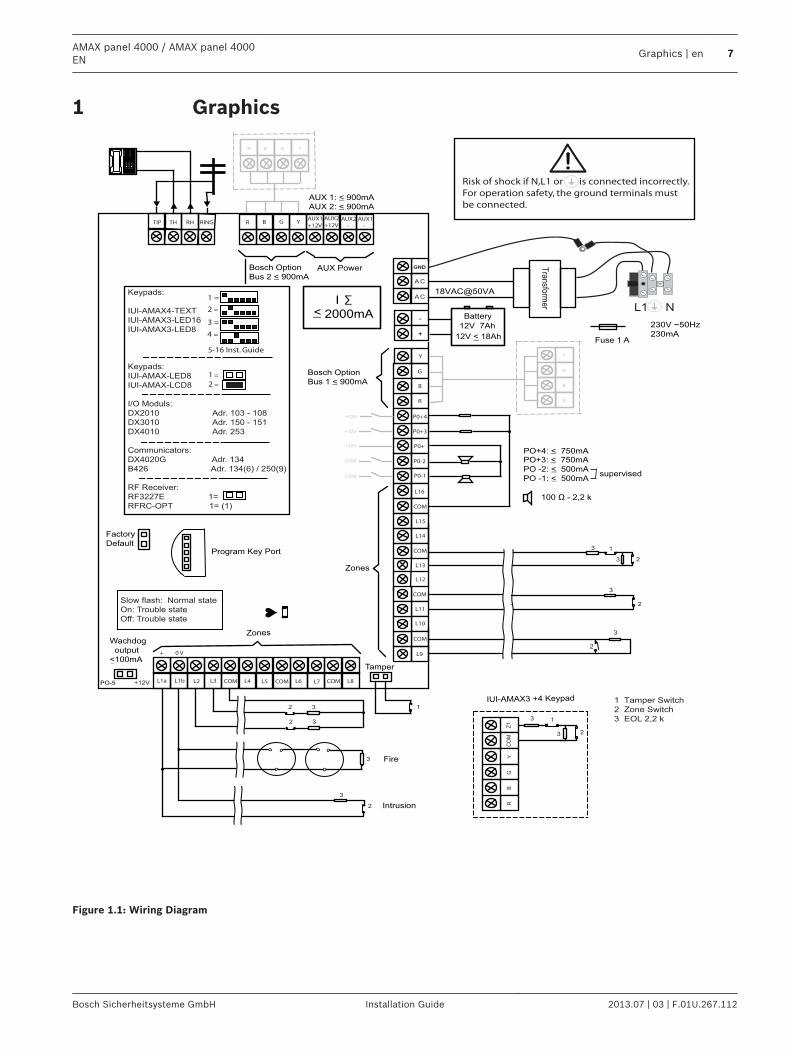
Graphics
Program Key Port
GND
-
+
A C
A C
Tra
nsfo
rme
r
Battery
Tamper
L2 COM COM COML1a L3 L4 L5 L6 L7 L8
L9
COM
COM
COM
COM
L10
L11
L12
L13
L14
L15
L16
P0+4
R
B
G
Y
AUX1
-
AUX2
-
AUX1
+12VYGBRRINGRHTHTIP
L1b
P0+3
P0+
P0-2
P0-1
Zones
Bosch Option
Bus 2 < 900mA
+12V
+ 0 V
1
2
3
3
1 Tamper Switch
2 Zone Switch
3 EOL 2,2 k
3
2
3
2
Fuse 1 A
PO+4: < 750mAPO+3: < 750mA
PO -2: < 500mA
PO -1: < 500mA
230V ~50Hz
230mA
Wachdog
output
<100mA
12V < 18Ah
18VAC@50VA
Zones
AUX 1: < 900mA
AUX 2: < 900mA
AUX Power
Fire
Intrusion
Risk of shock if N,L1 or is connected incorrectly.
For operation safety, the ground terminals must
be connected.
3
3
2Slow flash: Normal state
On: Trouble state
Off: Trouble state
_
_
_
_
_
_
_
_
+12V
+12V
+12V
COM
_
12V 7Ah
AUX2
+12V
_
COM supervised
PO-5
Z12
2 3
3
Keypads:
IUI-AMAX4-TEXT
IUI-AMAX3-LED16
IUI-AMAX3-LED8
Keypads:
IUI-AMAX-LED8
IUI-AMAX-LCD8
I/O Moduls:
DX2010 Adr. 103 - 108
DX3010 Adr. 150 - 151
DX4010 Adr. 253
Communicators:
DX4020G Adr. 134
B426 Adr. 134(6) / 250(9)
RF Receiver:
RF3227E 1=
RFRC-OPT 1= (1)
1 =
2 =
3 =
4 =
1 =
2 =
Bosch Option
Bus 1 < 900mA
CO
MR
BG
Y
R
B
G
Y
R B G Y
♥
IUI-AMAX3 +4 Keypad
3
1
2
1
Factory
Default
5-16 Inst. Guide
I
2000mA
100 Ω - 2,2 k
_ <
∑
3
Figure 1.1: Wiring Diagram
1
AMAX panel 4000 / AMAX panel 4000EN
Graphics | en 7
Bosch Sicherheitsysteme GmbH Installation Guide 2013.07 | 03 | F.01U.267.112
SafetyThis system / product must be installed by a qualified installer / service person.During installation and wiring, the control panel power source must be switched-off to preventequipment damage.– To switch off the Power Source, an easy accessible circuit breaker must be available.– The System / product must be connected to a socket-outlet with a protective earthing
contact The User has to disconnect all Telecommunication Network Connectors before unplug thepower adaptor. After the control panel wiring is completed, connect the AC power and backup batteries.The Mains indicator on the keypad will light to show that AC power is connected.
Notice!
- Use only non spillable battery
- Battery must be recycled
- When battery is not replaced correctly, risk of fire explosion or burning
- Replace the battery every 3-5 years under normal conditions of use.
- Place a Label with change date on the battery
Notice!
The system must be installed and maintained by qualified installer / service person.
Bosch recommends testing the whole alarm system at least once a week.
Maintenance should be done by qualified installer / service person four times a year.
Consequences
Danger!
As static-sensitive components are included in PCBs, anti-static steps should be followed and
they should be carefully installed.
Before installing the alarm control panel, the static electricity possibly carried should be
discharged by contacting the grounding terminal of the alarm control panel.
2
8 en | SafetyAMAX panel 4000 / AMAX panel 4000
EN
2013.07 | 03 | F.01U.267.112 Installation Guide Bosch Sicherheitsysteme GmbH
Short Information Congratulations on selecting the AMAX panel 4000 for your installation. Spend some timereading through this guide and familiarize yourself with the outstanding Operation andinstallation features of this system so that you can get the most from your unit. In all aspectsof planning, engineering, styling, operation, convenience and adaptability, we try to anticipateyour every possible requirement. Programming simplicity and speed are our majorconsiderations; we believe that our objectives have been attained. This installation guideexplains all aspects of programming the AMAX panel 4000 from factory default to finalcommissioning. All system parameters and options are dealt with in detail, but adaptabilitydiffers with individuals. Each control panel can be tailored to meet your requirements quicklyand easily. The programming simplicity makes your installation quick, accurate and rewarding.The AMAX panel 4000 equipped with 16 on-board wired zones can be expanded to 64 wiredzones.
3
AMAX panel 4000 / AMAX panel 4000EN
Short Information | en 9
Bosch Sicherheitsysteme GmbH Installation Guide 2013.07 | 03 | F.01U.267.112
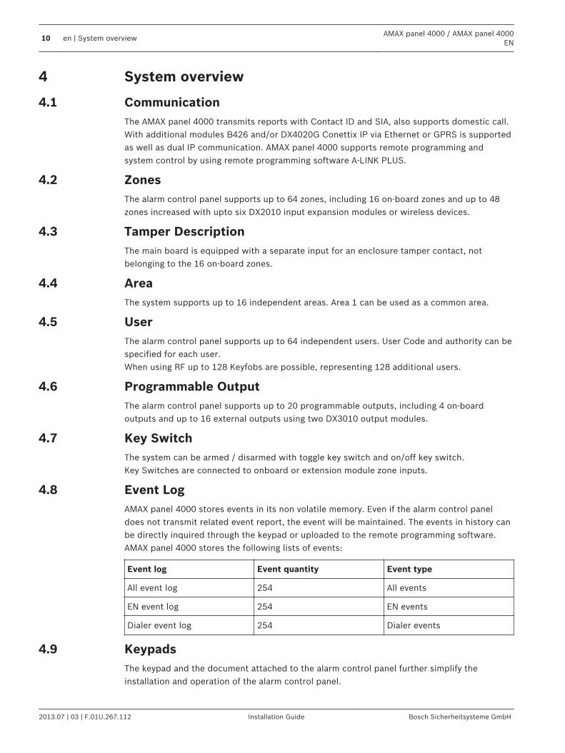
System overview
CommunicationThe AMAX panel 4000 transmits reports with Contact ID and SIA, also supports domestic call.With additional modules B426 and/or DX4020G Conettix IP via Ethernet or GPRS is supportedas well as dual IP communication. AMAX panel 4000 supports remote programming andsystem control by using remote programming software A-LINK PLUS.
ZonesThe alarm control panel supports up to 64 zones, including 16 on-board zones and up to 48zones increased with upto six DX2010 input expansion modules or wireless devices.
Tamper DescriptionThe main board is equipped with a separate input for an enclosure tamper contact, notbelonging to the 16 on-board zones.
AreaThe system supports up to 16 independent areas. Area 1 can be used as a common area.
UserThe alarm control panel supports up to 64 independent users. User Code and authority can bespecified for each user.When using RF up to 128 Keyfobs are possible, representing 128 additional users.
Programmable OutputThe alarm control panel supports up to 20 programmable outputs, including 4 on-boardoutputs and up to 16 external outputs using two DX3010 output modules.
Key SwitchThe system can be armed / disarmed with toggle key switch and on/off key switch.Key Switches are connected to onboard or extension module zone inputs.
Event LogAMAX panel 4000 stores events in its non volatile memory. Even if the alarm control paneldoes not transmit related event report, the event will be maintained. The events in history canbe directly inquired through the keypad or uploaded to the remote programming software.AMAX panel 4000 stores the following lists of events:
Event log Event quantity Event type
All event log 254 All events
EN event log 254 EN events
Dialer event log 254 Dialer events
Keypads The keypad and the document attached to the alarm control panel further simplify theinstallation and operation of the alarm control panel.
4
4.1
4.2
4.3
4.4
4.5
4.6
4.7
4.8
4.9
10 en | System overviewAMAX panel 4000 / AMAX panel 4000
EN
2013.07 | 03 | F.01U.267.112 Installation Guide Bosch Sicherheitsysteme GmbH
Optional Modules and Peripheral Devices
Keypad
Brief IntroductionThe system supports up to 16 keypads. Five supported keypads are as follows:– IUI-AMAX4-TEXT (LCD Text Keypad)– IUI-AMAX3-LED16 (16 Zone LED Keypad)– IUI-AMAX3-LED8 (8 Zone LED Keypad)– IUI-AMAX-LED8 (8 Zone LED Keypad)– IUI-AMAX-LCD8 (8 Zone LCD Keypad)
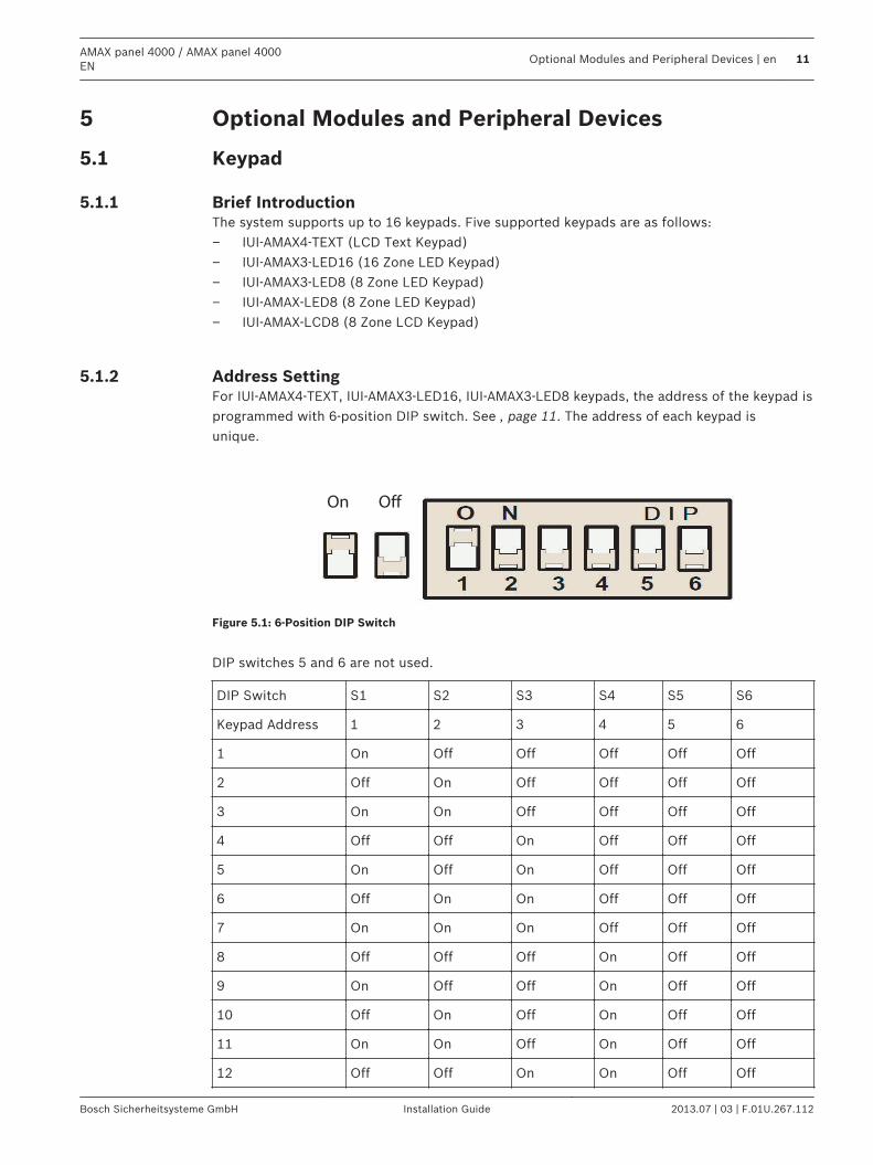
Address SettingFor IUI-AMAX4-TEXT, IUI-AMAX3-LED16, IUI-AMAX3-LED8 keypads, the address of the keypad isprogrammed with 6-position DIP switch. See , page 11. The address of each keypad isunique.
On Off
Figure 5.1: 6-Position DIP Switch
DIP switches 5 and 6 are not used.
DIP Switch S1 S2 S3 S4 S5 S6
Keypad Address 1 2 3 4 5 6
1 On Off Off Off Off Off
2 Off On Off Off Off Off
3 On On Off Off Off Off
4 Off Off On Off Off Off
5 On Off On Off Off Off
6 Off On On Off Off Off
7 On On On Off Off Off
8 Off Off Off On Off Off
9 On Off Off On Off Off
10 Off On Off On Off Off
11 On On Off On Off Off
12 Off Off On On Off Off
5
5.1
5.1.1
5.1.2
AMAX panel 4000 / AMAX panel 4000EN
Optional Modules and Peripheral Devices | en 11
Bosch Sicherheitsysteme GmbH Installation Guide 2013.07 | 03 | F.01U.267.112
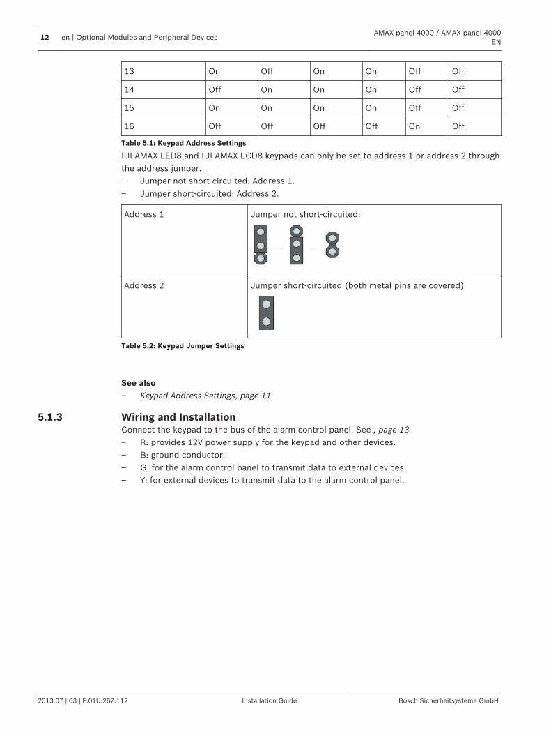
13 On Off On On Off Off
14 Off On On On Off Off
15 On On On On Off Off
16 Off Off Off Off On Off
Table 5.1: Keypad Address Settings
IUI-AMAX-LED8 and IUI-AMAX-LCD8 keypads can only be set to address 1 or address 2 throughthe address jumper.– Jumper not short-circuited: Address 1.– Jumper short-circuited: Address 2.
Address 1 Jumper not short-circuited:
Address 2 Jumper short-circuited (both metal pins are covered)
Table 5.2: Keypad Jumper Settings
See also– Keypad Address Settings, page 11
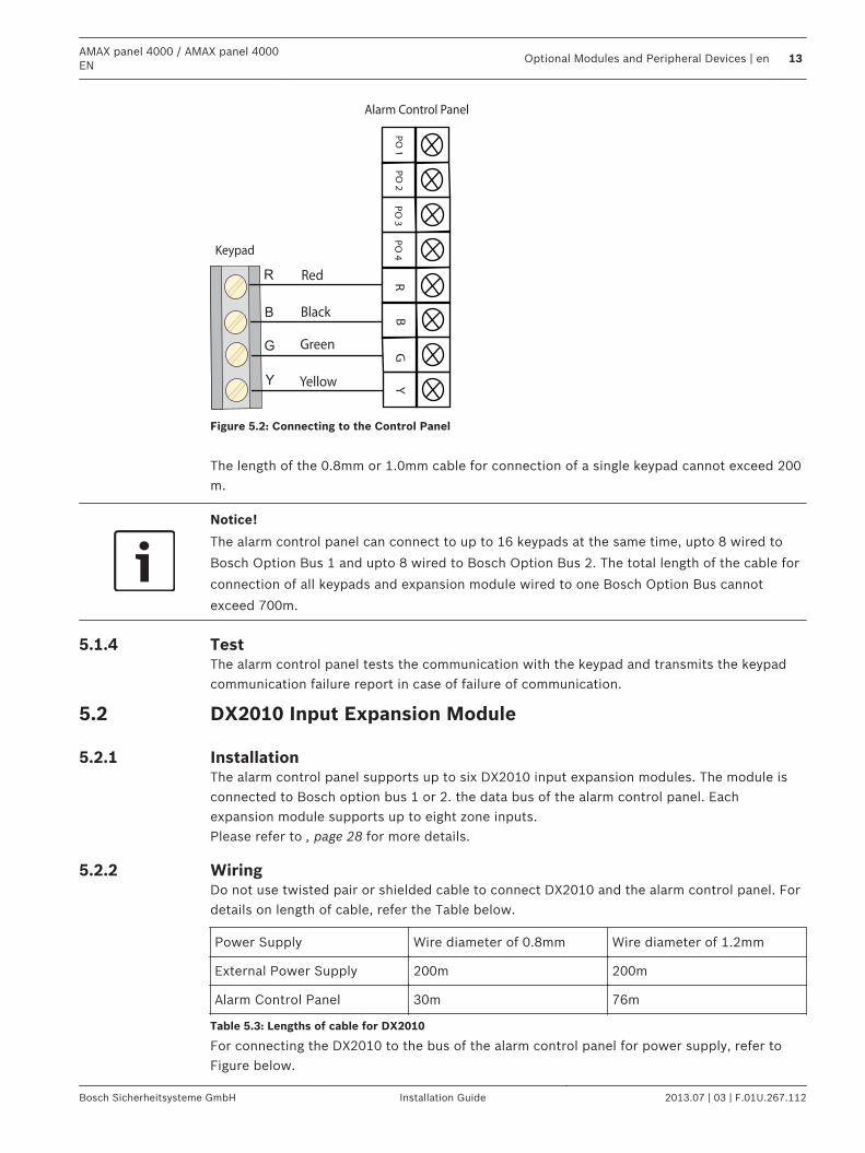
Wiring and InstallationConnect the keypad to the bus of the alarm control panel. See , page 13– R: provides 12V power supply for the keypad and other devices.– B: ground conductor.– G: for the alarm control panel to transmit data to external devices.– Y: for external devices to transmit data to the alarm control panel.
5.1.3
12 en | Optional Modules and Peripheral DevicesAMAX panel 4000 / AMAX panel 4000
EN
2013.07 | 03 | F.01U.267.112 Installation Guide Bosch Sicherheitsysteme GmbH
YG
BR
PO
1
R
B
G
Y
Keypad
Yellow
Green
Black
Red
Alarm Control Panel
PO
3P
O 4
PO
2
Figure 5.2: Connecting to the Control Panel
The length of the 0.8mm or 1.0mm cable for connection of a single keypad cannot exceed 200m.
Notice!
The alarm control panel can connect to up to 16 keypads at the same time, upto 8 wired to
Bosch Option Bus 1 and upto 8 wired to Bosch Option Bus 2. The total length of the cable for
connection of all keypads and expansion module wired to one Bosch Option Bus cannot
exceed 700m.
TestThe alarm control panel tests the communication with the keypad and transmits the keypadcommunication failure report in case of failure of communication.
DX2010 Input Expansion Module
InstallationThe alarm control panel supports up to six DX2010 input expansion modules. The module isconnected to Bosch option bus 1 or 2. the data bus of the alarm control panel. Eachexpansion module supports up to eight zone inputs.Please refer to , page 28 for more details.
WiringDo not use twisted pair or shielded cable to connect DX2010 and the alarm control panel. Fordetails on length of cable, refer the Table below.
Power Supply Wire diameter of 0.8mm Wire diameter of 1.2mm
External Power Supply 200m 200m
Alarm Control Panel 30m 76m
Table 5.3: Lengths of cable for DX2010
For connecting the DX2010 to the bus of the alarm control panel for power supply, refer toFigure below.
5.1.4
5.2
5.2.1
5.2.2
AMAX panel 4000 / AMAX panel 4000EN
Optional Modules and Peripheral Devices | en 13
Bosch Sicherheitsysteme GmbH Installation Guide 2013.07 | 03 | F.01U.267.112
YG
BR
AU
X 2
+A
UX
2-
AU
X 1
-A
UX
1+
R
B
G
Y
DX2010
Yellow
Green
Black (-)
Red (+)
Alarm Control Panel
TMPR
1
COM
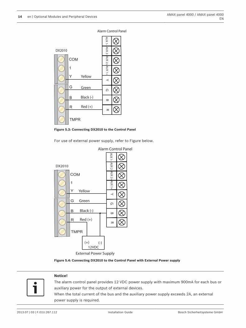
Figure 5.3: Connecting DX2010 to the Control Panel
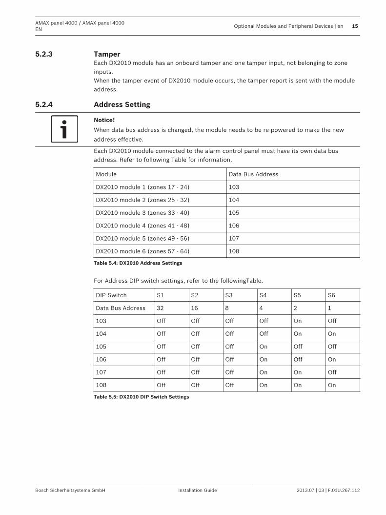
For use of external power supply, refer to Figure below.
YG
BR
AU
X 2
+A
UX
2-
AU
X 1
-A
UX
1+
R
B
G
Y
DX2010
Yellow
Green
Black (-)
Red (+)
Alarm Control Panel
TMPR
1
COM
(+) (-)12VDC
External Power Supply
Figure 5.4: Connecting DX2010 to the Control Panel with External Power supply
Notice!
The alarm control panel provides 12 VDC power supply with maximum 900mA for each bus or
auxiliary power for the output of external devices.
When the total current of the bus and the auxiliary power supply exceeds 2A, an external
power supply is required.
14 en | Optional Modules and Peripheral DevicesAMAX panel 4000 / AMAX panel 4000
EN
2013.07 | 03 | F.01U.267.112 Installation Guide Bosch Sicherheitsysteme GmbH
TamperEach DX2010 module has an onboard tamper and one tamper input, not belonging to zoneinputs.When the tamper event of DX2010 module occurs, the tamper report is sent with the moduleaddress.
Address Setting
Notice!
When data bus address is changed, the module needs to be re-powered to make the new
address effective.
Each DX2010 module connected to the alarm control panel must have its own data busaddress. Refer to following Table for information.
Module Data Bus Address
DX2010 module 1 (zones 17 - 24) 103
DX2010 module 2 (zones 25 - 32) 104
DX2010 module 3 (zones 33 - 40) 105
DX2010 module 4 (zones 41 - 48) 106
DX2010 module 5 (zones 49 - 56) 107
DX2010 module 6 (zones 57 - 64) 108
Table 5.4: DX2010 Address Settings
For Address DIP switch settings, refer to the followingTable.
DIP Switch S1 S2 S3 S4 S5 S6
Data Bus Address 32 16 8 4 2 1
103 Off Off Off Off On Off
104 Off Off Off Off On On
105 Off Off Off On Off Off
106 Off Off Off On Off On
107 Off Off Off On On Off
108 Off Off Off On On On
Table 5.5: DX2010 DIP Switch Settings
5.2.3
5.2.4
AMAX panel 4000 / AMAX panel 4000EN
Optional Modules and Peripheral Devices | en 15
Bosch Sicherheitsysteme GmbH Installation Guide 2013.07 | 03 | F.01U.267.112
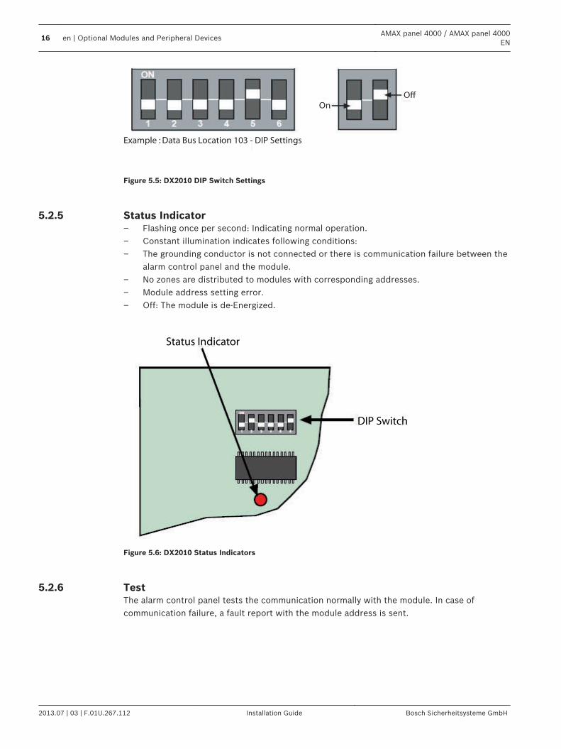
Example : Data Bus Location 103 - DIP Settings
On
Off
Figure 5.5: DX2010 DIP Switch Settings
Status Indicator– Flashing once per second: Indicating normal operation.– Constant illumination indicates following conditions:– The grounding conductor is not connected or there is communication failure between the
alarm control panel and the module.– No zones are distributed to modules with corresponding addresses.– Module address setting error.– Off: The module is de-Energized.
DIP Switch
Status Indicator
Figure 5.6: DX2010 Status Indicators
TestThe alarm control panel tests the communication normally with the module. In case ofcommunication failure, a fault report with the module address is sent.
5.2.5
5.2.6
16 en | Optional Modules and Peripheral DevicesAMAX panel 4000 / AMAX panel 4000
EN
2013.07 | 03 | F.01U.267.112 Installation Guide Bosch Sicherheitsysteme GmbH
DX3010 Output Expansion Module
InstallationThe alarm control panel supports up to two DX3010 output expansion modules. The module isconnected to Bosch option bus1 or 2. Each module supports eight fully programmable relayoutputs. Like on-board output, DX3010 can be programmed as the output following the areasuch as alarm event, arming / disarming status event and zone alarm event.For more information about installation, see DX3010 Installation Guide.Also refer to , page 28 for more details.
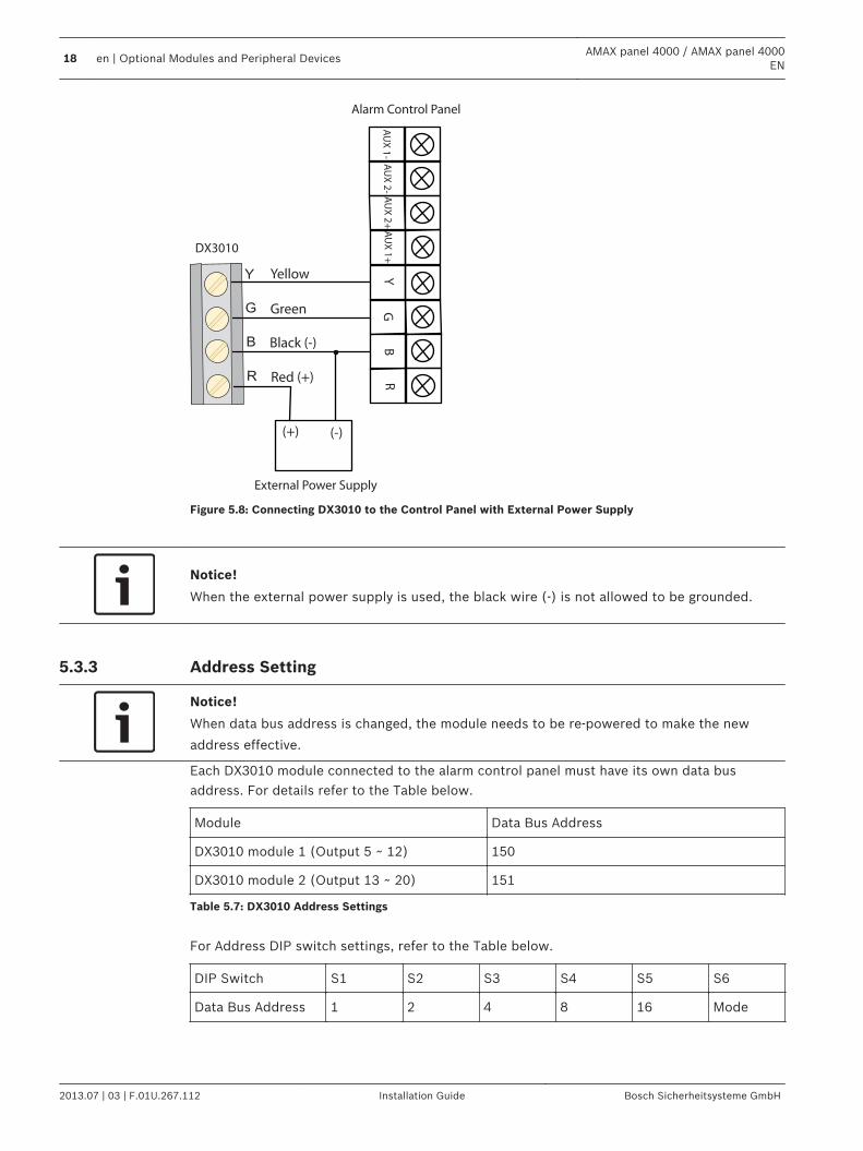
WiringWhen the module is placed in the enclosure of the alarm control panel, the power supply forthe control panel or external power supply can be used. For separate installation, the externalpower supply must be used.
Power Supply Wire diameter of 0.8mm Wire diameter of 1.2mm
Alarm Control Panel 12.2m 24.4m
External Power Supply 305m 610m
Table 5.6: Lengths of cable for DX3010
For details refer to the Figure below.
YG
BR
AU
X 2
+A
UX
2-
AU
X 1
-A
UX
1+
R
B
G
Y
DX3010
Yellow
Green
Black (-)
Red (+)
Alarm Control Panel
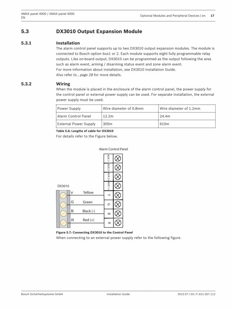
Figure 5.7: Connecting DX3010 to the Control Panel
When connecting to an external power supply refer to the following figure.
5.3
5.3.1
5.3.2
AMAX panel 4000 / AMAX panel 4000EN
Optional Modules and Peripheral Devices | en 17
Bosch Sicherheitsysteme GmbH Installation Guide 2013.07 | 03 | F.01U.267.112
YG
BR
AU
X 2
+A
UX
2-
AU
X 1
-A
UX
1+
R
B
G
Y
DX3010
Yellow
Green
Black (-)
Red (+)
Alarm Control Panel
External Power Supply
(+) (-)
Figure 5.8: Connecting DX3010 to the Control Panel with External Power Supply
Notice!
When the external power supply is used, the black wire (-) is not allowed to be grounded.
Address Setting
Notice!
When data bus address is changed, the module needs to be re-powered to make the new
address effective.
Each DX3010 module connected to the alarm control panel must have its own data busaddress. For details refer to the Table below.
Module Data Bus Address
DX3010 module 1 (Output 5 ~ 12) 150
DX3010 module 2 (Output 13 ~ 20) 151
Table 5.7: DX3010 Address Settings
For Address DIP switch settings, refer to the Table below.
DIP Switch S1 S2 S3 S4 S5 S6
Data Bus Address 1 2 4 8 16 Mode
5.3.3
18 en | Optional Modules and Peripheral DevicesAMAX panel 4000 / AMAX panel 4000
EN
2013.07 | 03 | F.01U.267.112 Installation Guide Bosch Sicherheitsysteme GmbH
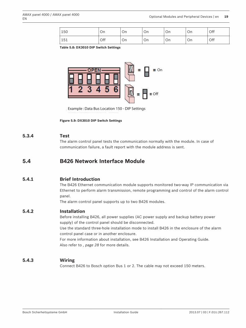
150 On On On On On Off
151 Off On On On On Off
Table 5.8: DX3010 DIP Switch Settings
Example : Data Bus Location 150 - DIP Settings
On
Off
Figure 5.9: DX3010 DIP Switch Settings
TestThe alarm control panel tests the communication normally with the module. In case ofcommunication failure, a fault report with the module address is sent.
B426 Network Interface Module
Brief IntroductionThe B426 Ethernet communication module supports monitored two-way IP communication viaEthernet to perform alarm transmission, remote programming and control of the alarm controlpanel.The alarm control panel supports up to two B426 modules.
InstallationBefore installing B426, all power supplies (AC power supply and backup battery powersupply) of the control panel should be disconnected.Use the standard three-hole installation mode to install B426 in the enclosure of the alarmcontrol panel case or in another enclosure.For more information about installation, see B426 Installation and Operating Guide.Also refer to , page 28 for more details.
WiringConnect B426 to Bosch option Bus 1 or 2. The cable may not exceed 150 meters.
5.3.4
5.4
5.4.1
5.4.2
5.4.3
AMAX panel 4000 / AMAX panel 4000EN
Optional Modules and Peripheral Devices | en 19
Bosch Sicherheitsysteme GmbH Installation Guide 2013.07 | 03 | F.01U.267.112
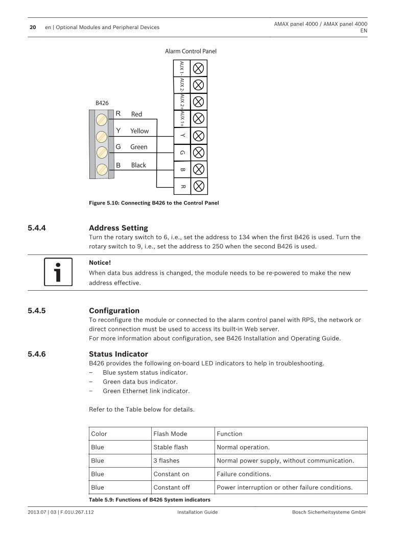
YG
BR
AU
X 2
+A
UX
2-
AU
X 1
-A
UX
1+
R
B
G
Y
B426
Yellow
Green
Black
Red
Alarm Control Panel
Figure 5.10: Connecting B426 to the Control Panel
Address SettingTurn the rotary switch to 6, i.e., set the address to 134 when the first B426 is used. Turn therotary switch to 9, i.e., set the address to 250 when the second B426 is used.
Notice!
When data bus address is changed, the module needs to be re-powered to make the new
address effective.
ConfigurationTo reconfigure the module or connected to the alarm control panel with RPS, the network ordirect connection must be used to access its built-in Web server.For more information about configuration, see B426 Installation and Operating Guide.
Status IndicatorB426 provides the following on-board LED indicators to help in troubleshooting.– Blue system status indicator.– Green data bus indicator.– Green Ethernet link indicator. Refer to the Table below for details.
Color Flash Mode Function
Blue Stable flash Normal operation.
Blue 3 flashes Normal power supply, without communication.
Blue Constant on Failure conditions.
Blue Constant off Power interruption or other failure conditions.
Table 5.9: Functions of B426 System indicators
5.4.4
5.4.5
5.4.6
20 en | Optional Modules and Peripheral DevicesAMAX panel 4000 / AMAX panel 4000
EN
2013.07 | 03 | F.01U.267.112 Installation Guide Bosch Sicherheitsysteme GmbH
For more information about indicators, see B426 Installation and Operating Guide.
TestThe alarm control panel tests the communication normally with the module. In case ofcommunication failure, a fault report with the module address is sent.
ITS-DX4020-G Communication Module
Brief IntroductionConettix ITS-DX4020-G GPRS communication module allows IP communication via commercialGPRS network. Transmission of alarm information via GPRS is the default for ITS-DX4020-G.SMS or USB mode can be chosen for configuration. The remote programming and control ofthe alarm control panel is supported.The alarm control panel supports up to two communication modules.– 1 ITS-DX4020-G and 1 B426, or– 2 B426
Installation1. Before installing ITS-DX4020-G, all power supplies of the control panel should be
disconnected.2. Insert SIM card.3. Use the standard three-hole installation mode to install ITS-DX4020-G in the enclosure of
the alarm control panel or another enclosure.4. Connect the magnetic antenna ITS-DX4020-G.
ConnectionWhen ITS-DX4020-G is used for communication with the alarm control panel, the bus addressshould be set to 134.The connection of ITS-DX4020-G and the alarm control panel is divided into two modes: GPRSand GSM.
5.4.7
5.5
5.5.1
5.5.2
5.5.3
AMAX panel 4000 / AMAX panel 4000EN
Optional Modules and Peripheral Devices | en 21
Bosch Sicherheitsysteme GmbH Installation Guide 2013.07 | 03 | F.01U.267.112
Alarm Control Panel
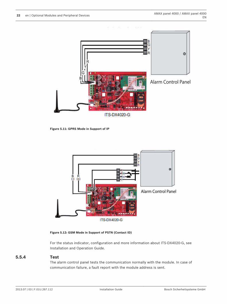
Figure 5.11: GPRS Mode in Support of IP
Alarm Control Panel
Figure 5.12: GSM Mode in Support of PSTN (Contact ID)
For the status indicator, configuration and more information about ITS-DX4020-G, seeInstallation and Operation Guide.
TestThe alarm control panel tests the communication normally with the module. In case ofcommunication failure, a fault report with the module address is sent.
5.5.4
22 en | Optional Modules and Peripheral DevicesAMAX panel 4000 / AMAX panel 4000
EN
2013.07 | 03 | F.01U.267.112 Installation Guide Bosch Sicherheitsysteme GmbH
RF 3227E RF Receiver
Brief IntroductionThe RF3227E RF Receiver allows the use of wireless devices using AMAX panel 4000.
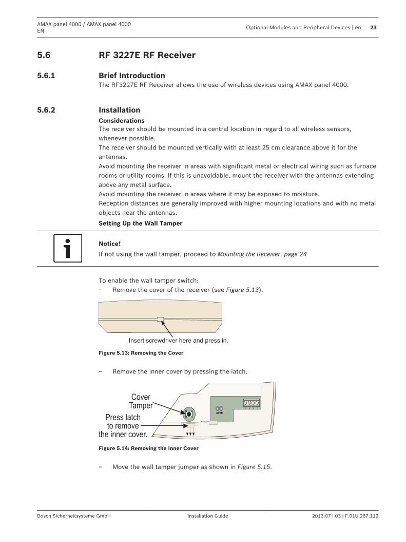
InstallationConsiderationsThe receiver should be mounted in a central location in regard to all wireless sensors,whenever possible.The receiver should be mounted vertically with at least 25 cm clearance above it for theantennas.Avoid mounting the receiver in areas with significant metal or electrical wiring such as furnacerooms or utility rooms. If this is unavoidable, mount the receiver with the antennas extendingabove any metal surface.Avoid mounting the receiver in areas where it may be exposed to moisture.Reception distances are generally improved with higher mounting locations and with no metalobjects near the antennas.
Setting Up the Wall Tamper
Notice!
If not using the wall tamper, proceed to Mounting the Receiver, page 24
To enable the wall tamper switch:– Remove the cover of the receiver (see Figure 5.13).
Insert screwdriver here and press in.
Figure 5.13: Removing the Cover
– Remove the inner cover by pressing the latch.
Press latchto remove
the inner cover.
CoverTamper R B G Y
ADDR
Figure 5.14: Removing the Inner Cover
– Move the wall tamper jumper as shown in Figure 5.15.
5.6
5.6.1
5.6.2
AMAX panel 4000 / AMAX panel 4000EN
Optional Modules and Peripheral Devices | en 23
Bosch Sicherheitsysteme GmbH Installation Guide 2013.07 | 03 | F.01U.267.112
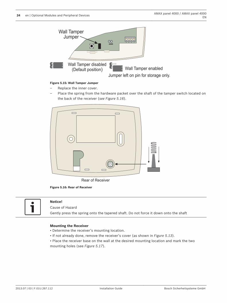
Wall TamperJumper
Wall Tamper disabled(Default position)
R B G Y
ADDR
Wall Tamper enabled
Jumper left on pin for storage only.
Figure 5.15: Wall Tamper Jumper
– Replace the inner cover.– Place the spring from the hardware packet over the shaft of the tamper switch located on
the back of the receiver (see Figure 5.16).
Rear of Receiver
Figure 5.16: Rear of Receiver
Notice!
Cause of Hazard
Gently press the spring onto the tapered shaft. Do not force it down onto the shaft
Mounting the Receiver• Determine the receiver’s mounting location.• If not already done, remove the receiver’s cover (as shown in Figure 5.13).• Place the receiver base on the wall at the desired mounting location and mark the twomounting holes (see Figure 5.17).
24 en | Optional Modules and Peripheral DevicesAMAX panel 4000 / AMAX panel 4000
EN
2013.07 | 03 | F.01U.267.112 Installation Guide Bosch Sicherheitsysteme GmbH
Bus and PowerConnector
Cover TamperSwitch
Mounting Holes
LED
R B G Y
ADDR
Antenna Connectors
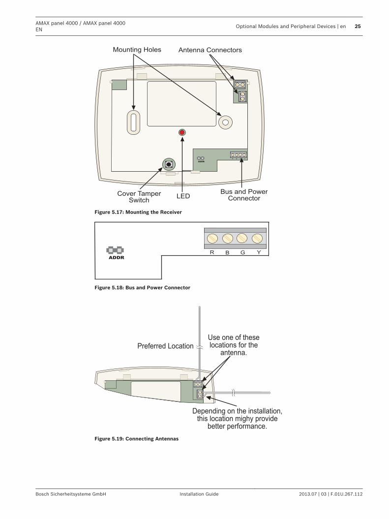
Figure 5.17: Mounting the Receiver
R B G Y
ADDR
Figure 5.18: Bus and Power Connector
Use one of theselocations for the
antenna.Preferred Location
Depending on the installation,this location mighy provide
better performance.
Figure 5.19: Connecting Antennas
AMAX panel 4000 / AMAX panel 4000EN
Optional Modules and Peripheral Devices | en 25
Bosch Sicherheitsysteme GmbH Installation Guide 2013.07 | 03 | F.01U.267.112
Address Setting
Notice!
When data bus address is changed, the module needs to be re-powered to make the new
address effective.
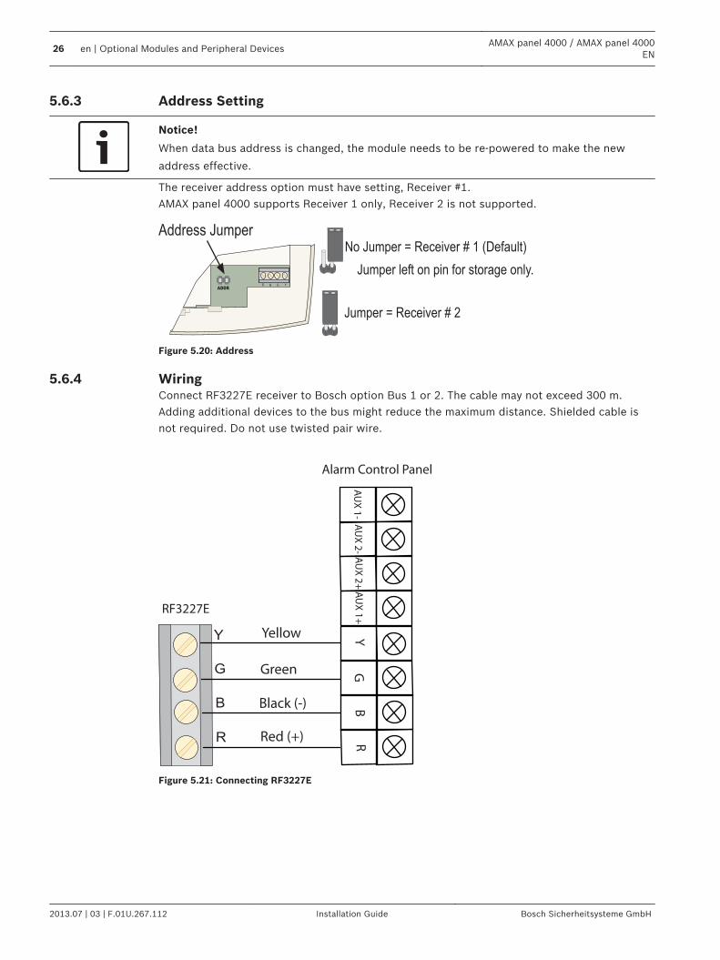
The receiver address option must have setting, Receiver #1.AMAX panel 4000 supports Receiver 1 only, Receiver 2 is not supported.
No Jumper = Receiver # 1 (Default)
Jumper = Receiver # 2
Address Jumper
Jumper left on pin for storage only.R B G Y
ADDR
Figure 5.20: Address
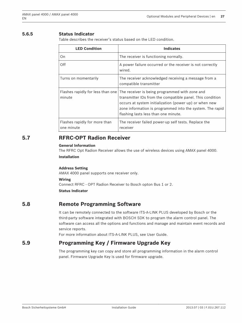
WiringConnect RF3227E receiver to Bosch option Bus 1 or 2. The cable may not exceed 300 m.Adding additional devices to the bus might reduce the maximum distance. Shielded cable isnot required. Do not use twisted pair wire.
YG
BR
AU
X 2
+A
UX
2-
AU
X 1
-A
UX
1+
R
B
G
Y
RF3227E
Yellow
Green
Black (-)
Red (+)
Alarm Control Panel
Figure 5.21: Connecting RF3227E
5.6.3
5.6.4
26 en | Optional Modules and Peripheral DevicesAMAX panel 4000 / AMAX panel 4000
EN
2013.07 | 03 | F.01U.267.112 Installation Guide Bosch Sicherheitsysteme GmbH
Status IndicatorTable describes the receiver’s status based on the LED condition.
LED Condition Indicates
On The receiver is functioning normally.
Off A power failure occurred or the receiver is not correctlywired.
Turns on momentarily The receiver acknowledged receiving a message from acompatible transmitter
Flashes rapidly for less than oneminute
The receiver is being programmed with zone andtransmitter IDs from the compatible panel. This conditionoccurs at system initialization (power up) or when newzone information is programmed into the system. The rapidflashing lasts less than one minute.
Flashes rapidly for more thanone minute
The receiver failed power-up self tests. Replace thereceiver
RFRC-OPT Radion ReceiverGeneral InformationThe RFRC Opt Radion Receiver allows the use of wireless devices using AMAX panel 4000.
Installation
Address SettingAMAX 4000 panel supports one receiver only.
WiringConnect RFRC - OPT Radion Receiver to Bosch opton Bus 1 or 2.
Status Indicator
Remote Programming SoftwareIt can be remotely connected to the software ITS-A-LINK PLUS developed by Bosch or thethird-party software integrated with BOSCH SDK to program the alarm control panel. Thesoftware can access all the options and functions and manage and maintain event records andservice reports.For more information about ITS-A-LINK PLUS, see User Guide.
Programming Key / Firmware Upgrade KeyThe programming key can copy and store all programming information in the alarm controlpanel. Firmware Upgrade Key is used for firmware upgrade.
5.6.5
5.7
5.8
5.9
AMAX panel 4000 / AMAX panel 4000EN
Optional Modules and Peripheral Devices | en 27
Bosch Sicherheitsysteme GmbH Installation Guide 2013.07 | 03 | F.01U.267.112
InstallationThis chapter specifies installation and system power up of the AMAX panel 4000. This system / product must be installed by a qualified installer / service person.During installation and wiring, the control panel power source must be switched-off to preventequipment damage.– To switch off the Power Source, an easy accessible circuit breaker must be available.– The System / product must be connected to a socket-outlet with a protective earthing
contact The User has to disconnect all Telecommunication Network Connectors before unplug thepower adaptor. After the control panel wiring is completed, connect the AC power and backup batteries.The power light on the keypad will light to show that AC power is connected.
Notice!
- Use only non spillable battery
- Battery must be recycled
- When battery is not replaced correctly, risk of fire explosion or burning
- Replace the battery every 3-5 years under normal conditions of use.
- Place a Label with change date on the battery
Notice!
The system must be installed and maintained by qualified installer / service person.
Bosch recommends testing the whole alarm system at least once a week.
Maintenance should be done by qualified installer / service person four times a year.
Module InstallationThe enclosure contains only PCBs and transformers of the fixed alarm control panel, not otherhardware for installation.1. Open the knockout holes for wiring in the module.2. Position two upper mounting holes on the installation wall with the module.3. Pre-install screws on the mounting holes (provided by the installer).4. Mount the screws on the module.5. Fasten the screws.6. Fix the two lower mounting holes with screws.
Notice!
Please choose appropriate positioning screw kit when installed in a non-load-bearing wall.
6
6.1
28 en | InstallationAMAX panel 4000 / AMAX panel 4000
EN
2013.07 | 03 | F.01U.267.112 Installation Guide Bosch Sicherheitsysteme GmbH
1 2
3 4
E N √ E N √
1 2
Enclosure - Standard
6.2 Enclosure with mounting plate Enclosure with mounting plate
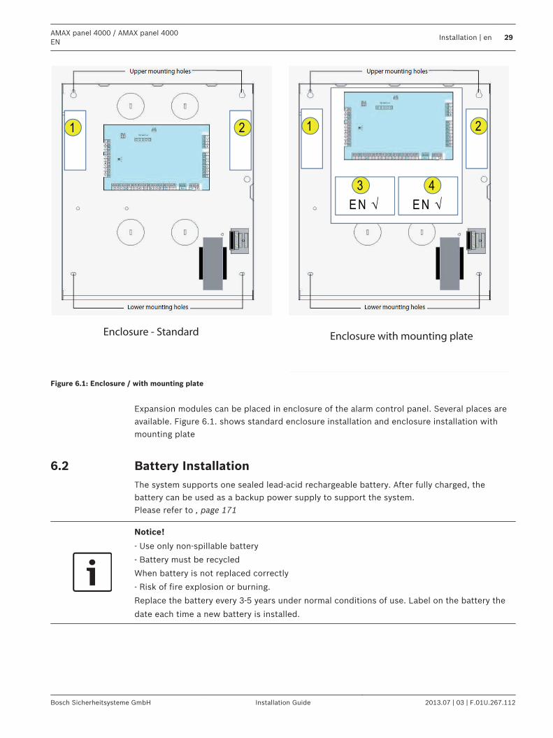
Figure 6.1: Enclosure / with mounting plate
Expansion modules can be placed in enclosure of the alarm control panel. Several places areavailable. Figure 6.1. shows standard enclosure installation and enclosure installation withmounting plate
Battery InstallationThe system supports one sealed lead-acid rechargeable battery. After fully charged, thebattery can be used as a backup power supply to support the system.Please refer to , page 171
Notice!
- Use only non-spillable battery
- Battery must be recycled
When battery is not replaced correctly
- Risk of fire explosion or burning.
Replace the battery every 3-5 years under normal conditions of use. Label on the battery the
date each time a new battery is installed.
6.2
AMAX panel 4000 / AMAX panel 4000EN
Installation | en 29
Bosch Sicherheitsysteme GmbH Installation Guide 2013.07 | 03 | F.01U.267.112
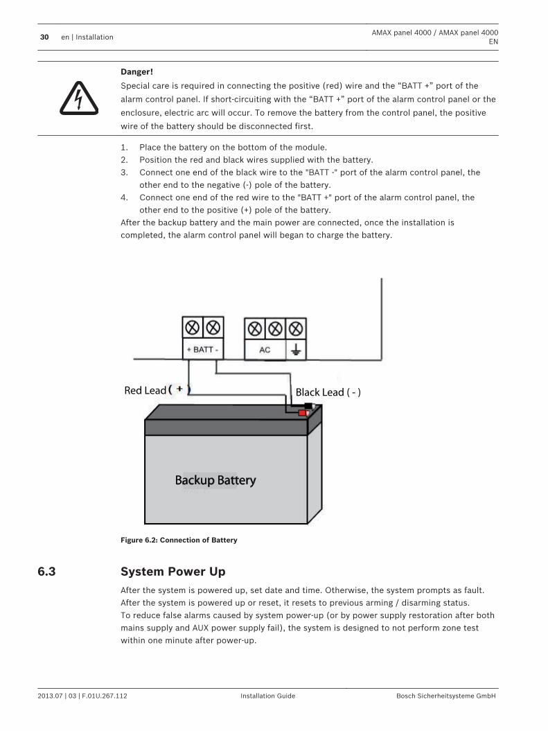
Danger!
Special care is required in connecting the positive (red) wire and the “BATT +” port of the
alarm control panel. If short-circuiting with the “BATT +” port of the alarm control panel or the
enclosure, electric arc will occur. To remove the battery from the control panel, the positive
wire of the battery should be disconnected first.
1. Place the battery on the bottom of the module.2. Position the red and black wires supplied with the battery.3. Connect one end of the black wire to the "BATT -" port of the alarm control panel, the
other end to the negative (-) pole of the battery.4. Connect one end of the red wire to the "BATT +" port of the alarm control panel, the
other end to the positive (+) pole of the battery.After the backup battery and the main power are connected, once the installation iscompleted, the alarm control panel will began to charge the battery.
Red Lead Black Lead ( - )
Backup Battery
Figure 6.2: Connection of Battery
System Power UpAfter the system is powered up, set date and time. Otherwise, the system prompts as fault.After the system is powered up or reset, it resets to previous arming / disarming status.To reduce false alarms caused by system power-up (or by power supply restoration after bothmains supply and AUX power supply fail), the system is designed to not perform zone testwithin one minute after power-up.
6.3
30 en | InstallationAMAX panel 4000 / AMAX panel 4000
EN
2013.07 | 03 | F.01U.267.112 Installation Guide Bosch Sicherheitsysteme GmbH
System Status IndicatorThe system status is indicated by the LED status indicator on the system main board.Slow flash of red status indicator (repeating on and off with an interval of 1 second) indicatesnormal system operation.
Prerequisites for Certification conform Installation
EN 50131-3 Grade 2, Environmental Class 2– System must be placed inside the monitored area on a stable surface.– Keypads must be mounted to the inner side of the monitored area.– Once the system is tested and ready to use, Enclosure Door and Accessory Enclosures
must be secured with the provided screws– To realize EN conform Alarm Indication and Transmission, one of the following options
must be used– Two supervised Warning devices (PO-1 PO-2 & PO+) and one ATS 2 Communicator
(onboard Dialer, B426, D4020 or DX4020G)– One self powered Warning Device and one ATS 2 Communicator (onboard Dialer,
B426, D4020 or DX4020G)– Two Communicators, one ATS 2 (onboard Dialer, B426, D4020 or DX4020G) and one
ATS 1 (onboard Dialer, B426, D4020 or DX4020G)– One ATS 3 Communicator (DX4020 or B426)
All Communicators must be connected to a Central Monitoring Station.Only the onboard Dialer and the Option Bus Communicators can be used for EN AlarmTransmission.– one 12V/7AH or one 12V/18Ah Battery must be connected to the System.– max current for all components with a 7Ah Battery = 550mAmax current for all components with a 18Ah Battery = 1500mA(standby 12h, recharge Battery 80% in 72h)(PCB=l00mA, IUI-AMAX Keypads=31mA, DX2010=35mA, DX3010=10mA, B426=100mA,DX4020G=65mA, RF3227E=30mA, RFRC-OPT=30mA)– To realize EN conform Arming procedure an indication of arm/disarm status must be
accessible from outside the monitored area (this indication can be time limited)– To realize EN conform Access to the Monitored Area, one of the following options must
be used– Opening a door (to the entry/exit route) must start the entry procedure– Indication of arm/disarm Status– Access to the monitored Area (doors not starting entry procedure) is prevented (e.g.
door strike, mechanically)The Enclosure lock can only be used in non EN setup.– Telephone arming can only be used in non EN setup.– Accessory Modules, except input module (DX2010) can be used only inside the enclosure
(on the adapter plate).– When input module (DX2010) is used in the external enclosure (AE20) the tamper skirt
must be installed on the PCB of input module (DX2010)– The panel must be programmed with the EN settings indicated on the programming
sheet. When the panel is set without EN parameters, the EN Indication (on Label) mustbe removed.
6.4
6.5
6.5.1
AMAX panel 4000 / AMAX panel 4000EN
Installation | en 31
Bosch Sicherheitsysteme GmbH Installation Guide 2013.07 | 03 | F.01U.267.112
SettingsThis chapter specifies the properties and the behavior of the AMAX panel 4000.
Communication and ReportingThis section outlines the programming information required for the AMAX panel 4000 / AMAXpanel 4000 EN when communicating with a base station receiver. These parameters specifythe telephone numbers/IP address to be called, transmission formats and internetcommunication options.
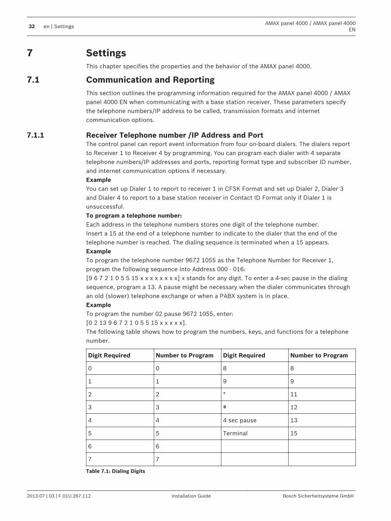
Receiver Telephone number /IP Address and PortThe control panel can report event information from four on-board dialers. The dialers reportto Receiver 1 to Receiver 4 by programming. You can program each dialer with 4 separatetelephone numbers/IP addresses and ports, reporting format type and subscriber ID number,and internet communication options if necessary.ExampleYou can set up Dialer 1 to report to receiver 1 in CFSK Format and set up Dialer 2, Dialer 3and Dialer 4 to report to a base station receiver in Contact ID Format only if Dialer 1 isunsuccessful.To program a telephone number:Each address in the telephone numbers stores one digit of the telephone number.Insert a 15 at the end of a telephone number to indicate to the dialer that the end of thetelephone number is reached. The dialing sequence is terminated when a 15 appears.ExampleTo program the telephone number 9672 1055 as the Telephone Number for Receiver 1,program the following sequence into Address 000 - 016:[9 6 7 2 1 0 5 5 15 x x x x x x x x] x stands for any digit. To enter a 4-sec pause in the dialingsequence, program a 13. A pause might be necessary when the dialer communicates throughan old (slower) telephone exchange or when a PABX system is in place.ExampleTo program the number 02 pause 9672 1055, enter:[0 2 13 9 6 7 2 1 0 5 5 15 x x x x x].The following table shows how to program the numbers, keys, and functions for a telephonenumber.
Digit Required Number to Program Digit Required Number to Program
0 0 8 8
1 1 9 9
2 2 * 11
3 3 # 12
4 4 4 sec pause 13
5 5 Terminal 15
6 6
7 7
Table 7.1: Dialing Digits
7
7.1
7.1.1
32 en | SettingsAMAX panel 4000 / AMAX panel 4000
EN
2013.07 | 03 | F.01U.267.112 Installation Guide Bosch Sicherheitsysteme GmbH
To program the IP Address and port:Use no punctuation in IP address. If any unit of IP address is less than 3 digits, use 0 to fulfillthe data in the higher bits. The remaining 5 digits will program the port. Port number rangesfrom 0-65535. Any port is less than 5 digits, use 0 to fulfil the data.ExampleTo program the IP Address 10.16.1.222:80 as the IP Address of Receiver 1, enter the followingsequence into Address 000 - 016:[0 1 0 0 1 6 0 0 1 2 2 2 0 0 0 8 0]
Notice!
Programming option anti-replay, acknowledge wait time and pulse interval time are only used
in Conettix IP.
Telephone number for Receiver 1 - 4/IP Address and PortWhen the corresponding data format for above programming address is a networkcommunication format, it is explained as an IP Address and Port. For a non network format, itis explained as telephone number.When the control panel transmits a report, it dials the telephone number/IP Address tocontact the monitoring station. If the call is successful, the relevant information is transmittedand the dialer returns to Standby Mode.Contact your monitoring station for the correct telephone number/IP Address before youprogram these addresses.
Receiver Subscriber ID NumberReceiver 1 - 4 Subscriber ID NumberThe Subscriber ID Number is transmitted to identify the calling control panel. Enter theSubscriber ID Number in the six addresses provided for each destination. If a Subscriber IDNumber is less than 6 digits, use 0 to full fill the data in the higher bits.ExampleProgram Subscriber ID Number as 4729 in six addresses: [0 0 4 7 2 9]
Receiver Transmission FormatTransmission FormatReceiver 1 - 4 Transmission FormatYou can select the transmission format with Address options to specify how to transmit theinformation to the base station receiver. If Contact ID or SIA format is selected, theinformation is transmitted by telephone line; if Bosch Network is selected, then it isconnected with B426/DX4020 or ITS-DX4020G GPRS. Transmission format is defaulted asContact ID.
Transmission Formats (Contact ID, SIA, Conettix IP)The AMAX panel 4000 / AMAX panel 4000 EN provides three kinds of transmission formats,Contact ID, SIA and Conettix IP format for its dialing and communication features. Programthe transmission format for Receiver 1, 2, 3 and 4 separately in Address 023, Address 053,Address 083 and Address 113 (refer to Transmission Format). The control panel is set at thefactory to report in the Contact ID Format.
7.1.2
7.1.3
AMAX panel 4000 / AMAX panel 4000EN
Settings | en 33
Bosch Sicherheitsysteme GmbH Installation Guide 2013.07 | 03 | F.01U.267.112
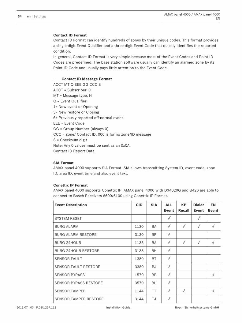
Contact ID FormatContact ID Format can identify hundreds of zones by their unique codes. This format providesa single-digit Event Qualifier and a three-digit Event Code that quickly identifies the reportedcondition.In general, Contact ID Format is very simple because most of the Event Codes and Point IDCodes are predefined. The base station software usually can identify an alarmed zone by itsPoint ID Code and usually pays little attention to the Event Code. – Contact ID Message FormatACCT MT Q EEE GG CCC SACCT = Subscriber IDMT = Message type, HQ = Event Qualifier1= New event or Opening3= New restore or Closing6= Previously reported off-normal eventEEE = Event CodeGG = Group Number (always 0)CCC = Zone/ Contact ID, 000 is for no zone/ID messageS = Checksum digitNote: Any 0 values must be sent as an 0x0A.Contact ID Report Data.
SIA FormatAMAX panel 4000 supports SIA Format. SIA allows transmitting System ID, event code, zoneID, area ID, event time and also event text.
Conettix IP FormatAMAX panel 4000 supports Conettix IP. AMAX panel 4000 with DX4020G and B426 are able toconnect to Bosch Receivers 6600/6100 using Conettix IP Format.
Event Description CID SIA ALLEvent
KPRecall
DialerEvent
ENEvent
SYSTEM RESET √ √
BURG ALARM 1130 BA √ √ √ √
BURG ALARM RESTORE 3130 BR √
BURG 24HOUR 1133 BA √ √ √ √
BURG 24HOUR RESTORE 3133 BH √
SENSOR FAULT 1380 BT √
SENSOR FAULT RESTORE 3380 BJ √
SENSOR BYPASS 1570 BB √ √
SENSOR BYPASS RESTORE 3570 BU √
SENSOR TAMPER 1144 TT √ √ √
SENSOR TAMPER RESTORE 3144 TJ √
34 en | SettingsAMAX panel 4000 / AMAX panel 4000
EN
2013.07 | 03 | F.01U.267.112 Installation Guide Bosch Sicherheitsysteme GmbH
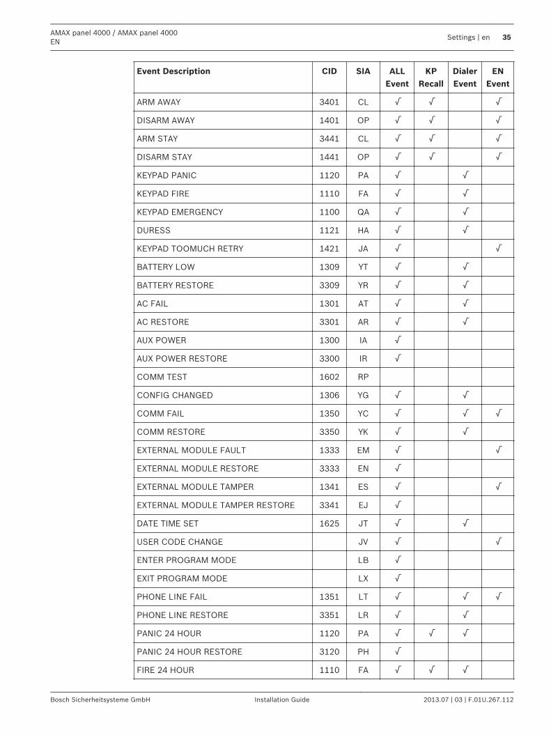
Event Description CID SIA ALLEvent
KPRecall
DialerEvent
ENEvent
ARM AWAY 3401 CL √ √ √
DISARM AWAY 1401 OP √ √ √
ARM STAY 3441 CL √ √ √
DISARM STAY 1441 OP √ √ √
KEYPAD PANIC 1120 PA √ √
KEYPAD FIRE 1110 FA √ √
KEYPAD EMERGENCY 1100 QA √ √
DURESS 1121 HA √ √
KEYPAD TOOMUCH RETRY 1421 JA √ √
BATTERY LOW 1309 YT √ √
BATTERY RESTORE 3309 YR √ √
AC FAIL 1301 AT √ √
AC RESTORE 3301 AR √ √
AUX POWER 1300 IA √
AUX POWER RESTORE 3300 IR √
COMM TEST 1602 RP
CONFIG CHANGED 1306 YG √ √
COMM FAIL 1350 YC √ √ √
COMM RESTORE 3350 YK √ √
EXTERNAL MODULE FAULT 1333 EM √ √
EXTERNAL MODULE RESTORE 3333 EN √
EXTERNAL MODULE TAMPER 1341 ES √ √
EXTERNAL MODULE TAMPER RESTORE 3341 EJ √
DATE TIME SET 1625 JT √ √
USER CODE CHANGE JV √ √
ENTER PROGRAM MODE LB √
EXIT PROGRAM MODE LX √
PHONE LINE FAIL 1351 LT √ √ √
PHONE LINE RESTORE 3351 LR √ √
PANIC 24 HOUR 1120 PA √ √ √
PANIC 24 HOUR RESTORE 3120 PH √
FIRE 24 HOUR 1110 FA √ √ √
AMAX panel 4000 / AMAX panel 4000EN
Settings | en 35
Bosch Sicherheitsysteme GmbH Installation Guide 2013.07 | 03 | F.01U.267.112
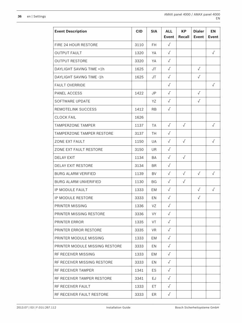
Event Description CID SIA ALLEvent
KPRecall
DialerEvent
ENEvent
FIRE 24 HOUR RESTORE 3110 FH √
OUTPUT FAULT 1320 YA √ √
OUTPUT RESTORE 3320 YA √
DAYLIGHT SAVING TIME +1h 1625 JT √ √
DAYLIGHT SAVING TIME -1h 1625 JT √ √
FAULT OVERRIDE √ √
PANEL ACCESS 1422 JP √ √
SOFTWARE UPDATE YZ √ √
REMOTELINK SUCCESS 1412 RB √
CLOCK FAIL 1626
TAMPERZONE TAMPER 1137 TA √ √ √
TAMPERZONE TAMPER RESTORE 3137 TH √
ZONE EXT FAULT 1150 UA √ √ √
ZONE EXT FAULT RESTORE 3150 UR √
DELAY EXIT 1134 BA √ √
DELAY EXIT RESTORE 3134 BR √
BURG ALARM VERIFIED 1139 BV √ √ √ √
BURG ALARM UNVERIFIED 1130 BG √ √
IP MODULE FAULT 1333 EM √ √ √
IP MODULE RESTORE 3333 EN √ √
PRINTER MISSING 1336 VZ √
PRINTER MISSING RESTORE 3336 VY √
PRINTER ERROR 1335 VT √
PRINTER ERROR RESTORE 3335 VR √
PRINTER MODULE MISSING 1333 EM √
PRINTER MODULE MISSING RESTORE 3333 EN √
RF RECEIVER MISSING 1333 EM √
RF RECEIVER MISSING RESTORE 3333 EN √
RF RECEIVER TAMPER 1341 ES √
RF RECEIVER TAMPER RESTORE 3341 EJ √
RF RECEIVER FAULT 1333 ET √
RF RECEIVER FAULT RESTORE 3333 ER √
36 en | SettingsAMAX panel 4000 / AMAX panel 4000
EN
2013.07 | 03 | F.01U.267.112 Installation Guide Bosch Sicherheitsysteme GmbH
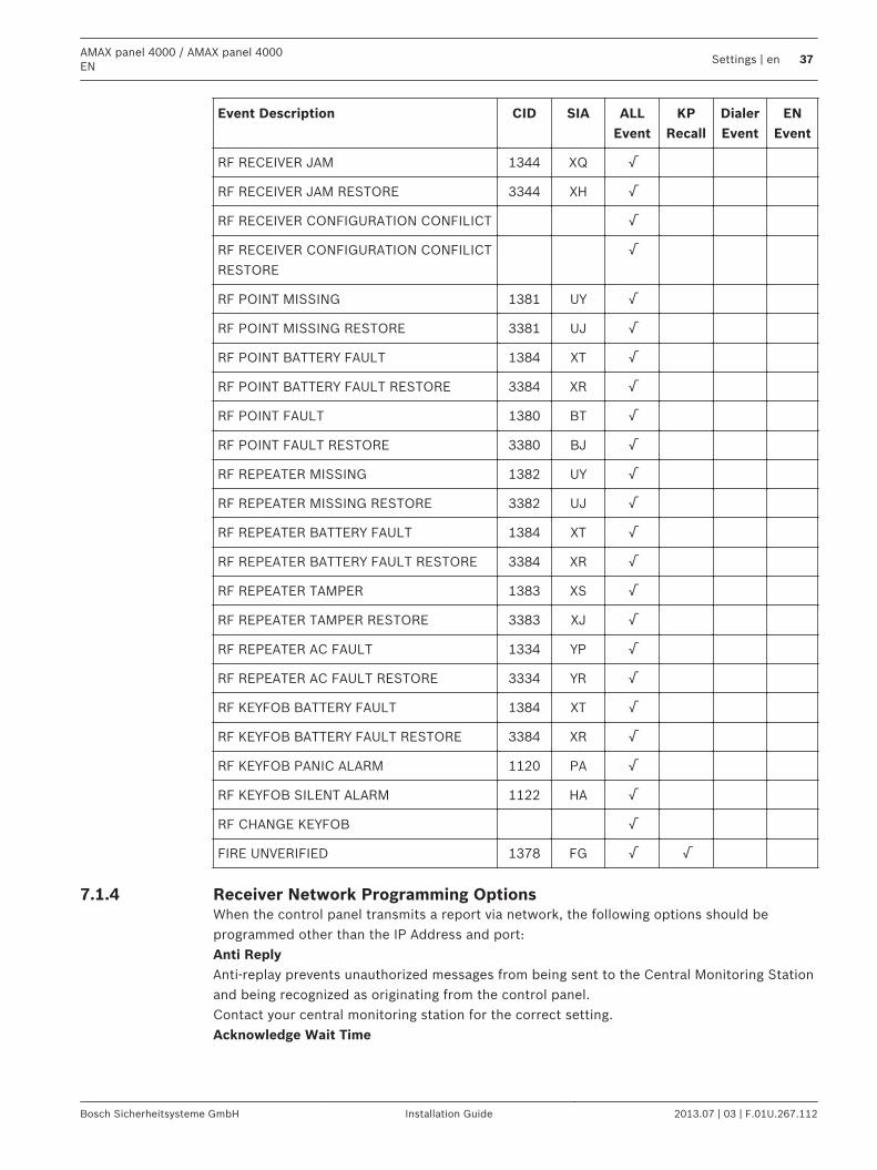
Event Description CID SIA ALLEvent
KPRecall
DialerEvent
ENEvent
RF RECEIVER JAM 1344 XQ √
RF RECEIVER JAM RESTORE 3344 XH √
RF RECEIVER CONFIGURATION CONFILICT √
RF RECEIVER CONFIGURATION CONFILICTRESTORE
√
RF POINT MISSING 1381 UY √
RF POINT MISSING RESTORE 3381 UJ √
RF POINT BATTERY FAULT 1384 XT √
RF POINT BATTERY FAULT RESTORE 3384 XR √
RF POINT FAULT 1380 BT √
RF POINT FAULT RESTORE 3380 BJ √
RF REPEATER MISSING 1382 UY √
RF REPEATER MISSING RESTORE 3382 UJ √
RF REPEATER BATTERY FAULT 1384 XT √
RF REPEATER BATTERY FAULT RESTORE 3384 XR √
RF REPEATER TAMPER 1383 XS √
RF REPEATER TAMPER RESTORE 3383 XJ √
RF REPEATER AC FAULT 1334 YP √
RF REPEATER AC FAULT RESTORE 3334 YR √
RF KEYFOB BATTERY FAULT 1384 XT √
RF KEYFOB BATTERY FAULT RESTORE 3384 XR √
RF KEYFOB PANIC ALARM 1120 PA √
RF KEYFOB SILENT ALARM 1122 HA √
RF CHANGE KEYFOB √
FIRE UNVERIFIED 1378 FG √ √
Receiver Network Programming OptionsWhen the control panel transmits a report via network, the following options should beprogrammed other than the IP Address and port:Anti ReplyAnti-replay prevents unauthorized messages from being sent to the Central Monitoring Stationand being recognized as originating from the control panel.Contact your central monitoring station for the correct setting.Acknowledge Wait Time
7.1.4
AMAX panel 4000 / AMAX panel 4000EN
Settings | en 37
Bosch Sicherheitsysteme GmbH Installation Guide 2013.07 | 03 | F.01U.267.112
When no callback from the receiver after the acknowledge time is reached, the control paneltakes it as an unsuccessful communication and makes another attempt. The time ranges from5 to 99 sec.Contact your central monitoring station for the correct setting.Network Polling TimeThe polling is used for both panel and remote receiver to know whether the networkconnection is good or not. Each time when a polling is due, the control panel will send apolling message. The polling time range is from 1 to 999 minutes. For time less than 3 digits,use 0 to fulfil.Contact your central monitoring station for the correct setting.
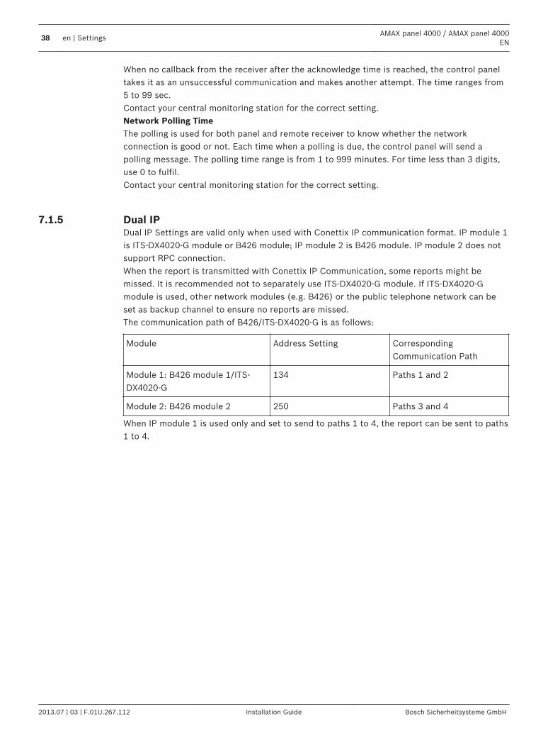
Dual IP Dual IP Settings are valid only when used with Conettix IP communication format. IP module 1is ITS-DX4020-G module or B426 module; IP module 2 is B426 module. IP module 2 does notsupport RPC connection.When the report is transmitted with Conettix IP Communication, some reports might bemissed. It is recommended not to separately use ITS-DX4020-G module. If ITS-DX4020-Gmodule is used, other network modules (e.g. B426) or the public telephone network can beset as backup channel to ensure no reports are missed.The communication path of B426/ITS-DX4020-G is as follows:
Module Address Setting CorrespondingCommunication Path
Module 1: B426 module 1/ITS-DX4020-G
134 Paths 1 and 2
Module 2: B426 module 2 250 Paths 3 and 4
When IP module 1 is used only and set to send to paths 1 to 4, the report can be sent to paths1 to 4.
7.1.5
38 en | SettingsAMAX panel 4000 / AMAX panel 4000
EN
2013.07 | 03 | F.01U.267.112 Installation Guide Bosch Sicherheitsysteme GmbH
System ReportingReport Transmission SequenceIf the event has disabled the report (option 0), no report is sent out. The domestic alarm is setas configured. If the report has any destination to contact the panel (option 1, 2, 3, 4, 5, 6, 7),It will call the related destination by related reporting format type and subscriber ID Number.Attempt rules:1. Attempt times and duration
– The attempt sequence is destination 1, 2, 3, 4 and domestic destination. Somedisabled destinations will be ignored.
– When a new report needs to be sent out, the system will send the report based onthe report destination programming list.
– For each enabled destination, the panel will retry sending the report to it till thereport has been sent to the destination, or till the report buffer overflows and theold report is replaced by new incoming reports.
– For each enabled destination, the retry interval time between two retries is 15seconds for the 1st retry to 4th retry, and the retry interval time between two retriesis 10 minutes for the 5th retry to 8th retry, after the 8th retry the retry interval timebetween two retries is 60 minutes.
– For all enabled destinations (except domestic destinations), the waiting time fornext retry would be cleared to zero as long as there is a new report.
2. Attempt Priority– The attempt priority is destination 1, 2, 3, 4, Domestic. The disabled destinations will
be ignored.3. Communication Fail Fault
– If the attempt times for one destination reaches 4, the system will cause thecommunication fail fault for this destination.
4. Backup Destination Process– If the destination failed for 4 attempts, the pending reports will switch between
primary/backup destinations in this group. If the report option selects 6, only onegroup: 1, 2, 3, 4 destinations. If the report option selects 7, there are two groups:group 1 is 1, 2 destinations. Group 2 is 3, 4 destinations. The system can save up toa maximum of 50 un-reported events. If the un-reported events are more than 50, itwill delete earlier events and only save the last 50 events in the buffer to send out.
Sequential Logic to Send Report– If the event reporting path is set to 0, the relevant reports will not be sent.– If the event reporting path is set to a single path (receiver 1, 2, 3 or 4), the alarm control
panel will send reports to corresponding paths. Path 1, 2 3 or 4 fault will result in path 1,2, 3 or 4 communication fault; Path 1, 2 3 or 4 recovery will result in communication path1, 2, 3 fault recovery.
– If the event reporting path is set to all paths (receiver 1, 2, 3, 4), the alarm control panelwill send reports to corresponding paths. Any one of these paths fails, the communicationpath will fail; the path recovers, the communication path fault will recover.
– If the event reporting path is set to sending report to receiver 1, with receiver 2, 3, 4 asbackup, the alarm control panel will send reports to corresponding paths. Send to path 2when the attempt to send to path 1 fails; Send to path 3 when the attempt to send topath 2 fails; Send to path 4 when the attempt to send to path 3 fails; communication path1 fault will occur when all valid paths fail; communication path 1 fault will recover whenany one of the paths recovers.
7.1.6
AMAX panel 4000 / AMAX panel 4000EN
Settings | en 39
Bosch Sicherheitsysteme GmbH Installation Guide 2013.07 | 03 | F.01U.267.112
– If the event reporting path is set to sending report to receiver 1, receiver 2 as backup;sending report to receiver 3, receiver 4 as backup; the alarm control panel will sendreports to corresponding paths.
Communication path 1 fault will occur when path 1 and valid path 2 fail; communication path1 fault will recover when fault 1 or 2 recovers. Communication path 3 fault will occur when path 3 and valid path 4 fail; communication path3 fault will recover when fault 3 or 4 recovers. The attempt rules to send reports are as follows: 1 - Number and time of attempts to send reportWhen CID format or Conettix IP communication format is used for all, the order of priority ofattempts is path 1, 2, 3, 4, personal alarm telephone 1 - 4. The unused paths are ignored.When a new event report occurs, the system will send reports in accordance with thespecified path.For each reporting path used, the alarm control panel will repeatedly try until the report issuccessfully sent.For each reporting path used, the interval of the first 4 attempts is 15 seconds, the interval ofthe fifth to eighth attempt is 10 seconds, and the interval afterwards is 60 seconds.For each reporting path used (excluding personal telephone alarm), if a new event occurs, thewaiting time for the next retry will be cleared. If the newly-occurred event is communicationpath fault, the previous retry logic will not be affected (the waiting time will not be cleared). 2 – The order of priority of attempts to send reportWhen CID format or Conettix IP communication format is used for all, the order of priority ofsending report is path 1, 2, 3, 4, personal alarm telephone 1 - 4. Some unused paths will beignored. 3 – Communication failure faultWhen a report is still not successfully sent after the reporting path has been attempted for upto 4 times, the system will generate the communication failure fault event of the path. 4 – Backup eventIf an event is not successfully sent, the alarm control panel will provide a buffer to store up to50 events. If more than 50 events are not successfully sent, only the last 50 events will bestored in the buffer until the events are delivered. Other earlier events will be deleted. 5 - Display of faultsWhen multiple reports are queued for delivery, the communication path fault is displayed aslogic or relationship. Example:Set zone status recovery report to send report to receiver 1; set keypad emergency report tosend report to receiver 1, with receiver 2, 3, 4 as backup.Communication path fault is as follows: When communication paths 1, 2, 3, and 4 all fail, asthe communication path fault is displayed as logic or relationship, only the illumination of zoneindicator 1 expresses that the communication path 1 of the zone status recovery report failsand the all communication paths 1, 2, 3 and 4 of the keypad emergency report fail as well.Communication path fault recovery is as follows:
40 en | SettingsAMAX panel 4000 / AMAX panel 4000
EN
2013.07 | 03 | F.01U.267.112 Installation Guide Bosch Sicherheitsysteme GmbH
– When communication path 1 fault recovers, zone indicator 1 goes off, indicating that thecommunication path 1 fault of the zone status recovery report recovers and thecommunication part 1 fault of the keypad emergency report recovers.
– When any one path fault of communication paths 2, 3 and 4 recovers, as thecommunication path fault is displayed as logic or relationship, zone indicator 1 stillilluminates, indicating that the communication path 1 fault of the zone status recoveryreport has not be recovered, but the path fault of the keypad emergency report has beenrecovered
Zone Status Reporting and Zone Recovery ReportingAlarm ReportIn arming status, in case of alarm event, the alarm report will be sent. Alarm Recovery ReportIn arming status, when the zone recovers, the zone recovery report will be sent at the end ofalarm output time.If the non-24-hour zone is not recovered in disarming, the system will automatically send azone recovery report. The 24-hour zone sends zone recovery report only when the zonerecovers. Zone Fault ReportIf the zone is in triggering status at the end of exit delay, a zone fault report will be sent,indicating that the zone is automatically bypassed by the system. At the end of exit delay time,the 24-hour zone in triggering status will not send zone fault report, i.e., the 24-hour zone willnot be automatically bypassed.The non 24-hour zone fault recovery report will be sent when the zone recovers or the systemdisarms. For the 24-hour zone, only the alarm recovery event will occur.The zone fault occurs when the zone is triggered and recovers when the zone is normal. Zonefault will occur when one of the following conditions is met:– For 24-hour zone, (internal) instant zone, if the forced arming option is set to allow, the
zone fault event will occur when the arming operation is executed while the zone is intriggering status.
– When the zone is locked.– For (internal) delay and (internal) follow zone, if they are still in triggering status at the
end of exit delay, zone fault event will occur.– For 24-hour zone, if it is in triggering status when the bypass is cancelled, zone fault
event will occur.Fault recovery conditions:– Zone resumes to normal conditions.– When the failed (internal) delay zone, (internal) instant zone and (internal) follow zone
are disarmed, the fault recovery event will occur even if the zone is still in triggeringstatus.
Zone Bypass ReportAfter the manual bypass zone is operated, the zone will be bypassed. The zone bypass reportwill be sent at the end of exit delay time. The bypass report of the 24-hour zone will be sentimmediately after manual bypass operation.The zone bypass will be recovered when the system is disarmed and the zone bypass recoveryreport will also be sent while disarming.
AMAX panel 4000 / AMAX panel 4000EN
Settings | en 41
Bosch Sicherheitsysteme GmbH Installation Guide 2013.07 | 03 | F.01U.267.112
Zone Tamper AlarmIn case of zone tamper event, the tamper report will be sent. When zone tamper recovers, thesystem status report will be sent.
Arming/Disarming Reporting (System)The system disarming report is sent at the disarming command and the system arming reportis sent when the arming succeeds.Duress ReportThe duress report is sent at the disarming command. The duress report will not be sent in theoperation of arming, but sent as ordinary arming report. The duress report has notcorresponding alarm recovery report.Key Switch ArmingSend system arming report when the transient key switch or locking key switch is used to armareas.Quick ArmingSend system arming report when the keypad is used for quick arming.Telephone ArmingSend system arming report when the telephone is used for arming of the panel.Telephone arming is only available when there is only 1 Area in the system.RPC ArmingSend system arming report when the remote PC is used to arm areas through network ortelephone connection.
Arming/Disarming Reporting (Perimeter)The perimeter disarming report is sent at the disarming command and the perimeter armingreport is sent when the arming succeeds.Quick ArmingSend perimeter arming report when the keypad is used for quick arming.RPC ArmingSend perimeter arming report when the remote PC is used to arm areas through network ortelephone connection.
System Status ReportingExternal Module Fault Report– System tamper report: In case of case tamper event, the system tamper report will be
sent. When case tamper recovers, a tamper recovery report will be sent.– Zone Expansion Module Fault: When zone expansion module 1 – 6 fails, the report will be
sent; after the fault is recovered, the recovery report will be sent.– Output Expansion Module Fault: When output expansion module 1 or 2 fails, the report
will be sent; after the fault is recovered, the recovery report will be sent.– Network Module Fault: When network module 1 or 2 fails, the report will be sent; after
the fault is recovered, the recovery report will be sent.– Keypad Fault: When fault occurs between the keypad and the alarm control panel, the
report will be sent; after the fault is recovered, the recovery report will be sent.– Zone Expansion Module Tamper: When tamper occurs in the zone expansion module, the
tamper report will be sent; when the tamper recovers, a tamper recovery report will besent.
– Keypad Tamper: When tamper occurs in any keypads, the tamper report will be sent;when the tamper recovers, a tamper recovery report will be sent.
42 en | SettingsAMAX panel 4000 / AMAX panel 4000
EN
2013.07 | 03 | F.01U.267.112 Installation Guide Bosch Sicherheitsysteme GmbH
Auxiliary Power Fault ReportWhen the system detects auxiliary power fault, the report will be sent.Auxiliary Power Fault Restore ReportWhen the system detects auxiliary power fault recovery, the report will be sent.AC Power Fault ReportWhen the system detects disconnection of AC power, the report will be sent.AC Power Fault Recovery ReportWhen the system detects recovery of AC power, the report will be sent.Battery Low Voltage Fault ReportWhen the battery voltage is lower than 11.0V or battery low voltage is detected in dynamicbattery test, the alarm control panel will send battery low voltage report.The system continuously monitors the battery voltage and will perform a dynamic battery testeach time the system is armed, when the system is reset, or every 4 hours.Battery Low Voltage Fault Recovery ReportWhen the battery voltage is lower than 12.0V or recovery to normal voltage is detected indynamic battery test, the battery low voltage fault recovery report will be sent.Times of Wrong Code Entry Exceeding LimitWhen the times of entering wrong code reach the specified one, an access denial report willbe generated and alarm will be made.This function limits the times of malicious attempts of password by the unauthorized user.When the times of entering wrong password reach the specified one by programming, thealarm control panel will execute following actions:– Activate alarm siren and other alarm output.– Lock all keypads for 3 minutes.– Send access denial report.On-board Output 1 – 2 FaultWhen on-board output 1 or 2 fails, the report will be sent. When the on-board output resumesto normal conditions, the programmable output fault recovery report will be sent.Communication Path 1 - 4 FaultWhen any communication paths fail, the report will be sent. When the communicationresumes to normal conditions, the communication fault recovery report will be sent.Changing Programming ParametersWhen the programming parameters are changed and take effect, the report will be sent.
Keypad Emergency Alarm ReportingTo press and hold both [1] and [3] for 3 seconds, or press and hold both [#] and [*] for 3seconds, the emergency alarm report will be sent.The emergency alarm report has not corresponding alarm recovery report.
Keypad Fire Alarm ReportingTo press and hold both [4] and [6] for 3 seconds, the fire alarm report will be sent.The fire alarm report has not corresponding alarm recovery report.
Keypad Medical Aid ReportingTo press and hold both [7] and [9] for 3 seconds, the medical aid alarm report will be sent.The medical aid alarm report has not corresponding alarm recovery report.
Automatic Test ReportingThe system supports sending automatic test report.
AMAX panel 4000 / AMAX panel 4000EN
Settings | en 43
Bosch Sicherheitsysteme GmbH Installation Guide 2013.07 | 03 | F.01U.267.112
For more information about test report time programming, see Test Report Time. For moreinformation about date and time settings, see Date and Time Settings.
Automatic Test ReportThe test report is divided into two types: periodic and regular daily report.– When the address 0129-0130 is programmed to 1-99, the system will send periodic
automatic test report every hours specified by the address. If 0129-0130 is programmedto 0, no periodic test reports will be sent.
– When 0131-0134 is set to valid time, the system will send automatic test report at thesame time every day. At this moment, the date and time of the system must be correctlyset. If 0131-0134 is set to be invalid time, the daily regular automatic test report will bedisabled.
Report Expiry TimeIf the report expiry time expires and the report path has not been connected, the report willbe lost and will not be sent. It can be maintained for 1 to 255 minutes. The system isdefaulted to 000, indicating that the report has been tried to send without limit in expiry time.
Remote PC SettingsBy means of running Remote Programming Software (RPS) on a remote PC (RPC), the alarmcontrol panel can be remotely programming or controlled, including uploading/downloadingprogramming parameters, remote arming/disarming of each area, enabling/disabling the alarmsiren of each area, enabling/disabling each output, etc.Remote Programming Software, i.e. RPS, includes Bosch A-Link Plus software and the third-party software of integrated with Bosch SDK.The IP remote connection function allows to establish a connection from the remote PC to thealarm control panel through LAN or WAN to perform remote programming and control.While the connection is established, alarm control panel sends a polling telegram of 25 bytes.
IP AddressRPC IP address is a fixed IP address for remote programming software.
Port NumberRPC port number is the port number of the remote programming software.
DHCP Update / RPC poll Time IntervalDHCP update / RPC poll time is the interval the alarm control panel connects to the RPC(Remote Programming PC).The alarm control panel send UDP data packets to the RPC according to the DHCP UpdateTime Interval setting (0=disabled 1-15h Interval), when the Panel is reset and when call back isfinished.RPC get the Subscriber ID, IP address and port from the UDB data packets (IP No. and Port isparsed from UDP data packet).RPC with running RPS (Remote Programming Software = A-Link Plus) saves the received UDPdata packet information’s into its own RAM, the information is lost after RPS is closed.When a connection is started and the IP address set in the Customer Information doesn’tmatch with the IP Address from the Ram, A-Link opens a window to ask if the new IP Addressand Port should be used.
7.1.7
7.1.8
7.1.9
44 en | SettingsAMAX panel 4000 / AMAX panel 4000
EN
2013.07 | 03 | F.01U.267.112 Installation Guide Bosch Sicherheitsysteme GmbH
When RPS is opened, a connection can only be established when the IP address and portnumber of the alarm control panel have not changed, after RPS received previous data..If the IP address has changed RPC with running RPS must wait for the next UDP Data packagesend from the Panel.
Number of RingsThe address sets the number of rings of the alarm control panel before answering incomingcalls. Please set proper number of rings. This setting is only related to the connection ofremote programming software by means of telephone. Setting this address to 0 can disablethe alarm control panel to answer all incoming calls no matter how other programmingaddresses are set.
Telephone Remote ConnectionUse telephone to remotely program and control the system.For telephone remote connection to enable programming, see Telephone Remote Connection.
Call back Telephone NumberThis address stores the telephone number to call when Upload/Download is requested or theuser enters his code + [5][7] and presses [#] to initiate a modem call from the control panelto establish a communication link with the remote computer. The computer must be runningA-Link Plus RPS software and must be set to Waiting for an Incoming Call. The Call BackTelephone Number is also necessary if remote connect with call back verification is required.
Ring CountThis address sets the number of rings before the control panel answers an incoming call.Setting this count to an acceptable level has an effect only if Remote Arming and the RemoteUpload/Download are enabled. Programming this address to 0 prevents the control panel fromanswering incoming calls regardless of any other programmed options.
Domestic CallFour dialing telephone numbers will be supported.When the control panel is activated into zone tamper/ zone alarm, it dials the programmedtelephone number.All alarm events only need one report/acknowledgement.The transmission sequence is repeated until the control panel receives an acknowledgementtone.The control panel automatically hangs up after 45 seconds if it cannot detect theacknowledgement tone. And redial later.The user presses [#] between two acknowledgement tones to confirm the alarming.The acknowledgement tone is the DTMF signal sent by the remote user with the [#] .If the control panel got the [#] acknowledgement from the user, it will send 2 seconds longbeep as acknowledge tone and hang up the line.
7.1.10
AMAX panel 4000 / AMAX panel 4000EN
Settings | en 45
Bosch Sicherheitsysteme GmbH Installation Guide 2013.07 | 03 | F.01U.267.112
Zones
Zone InputsOn-board Inputs:There are 8 onboard hard-wired inputs for AMAX panel 4000 / AMAX panel 4000 EN. Anadditional input is provided for enclosure tamper but does not subtract from the 8 onboardtotals.
On-board Zone Response Time:Each on-board zone response time is:Zone Status trigger time >= 400ms, must responseZone Status trigger time < 300ms, no response
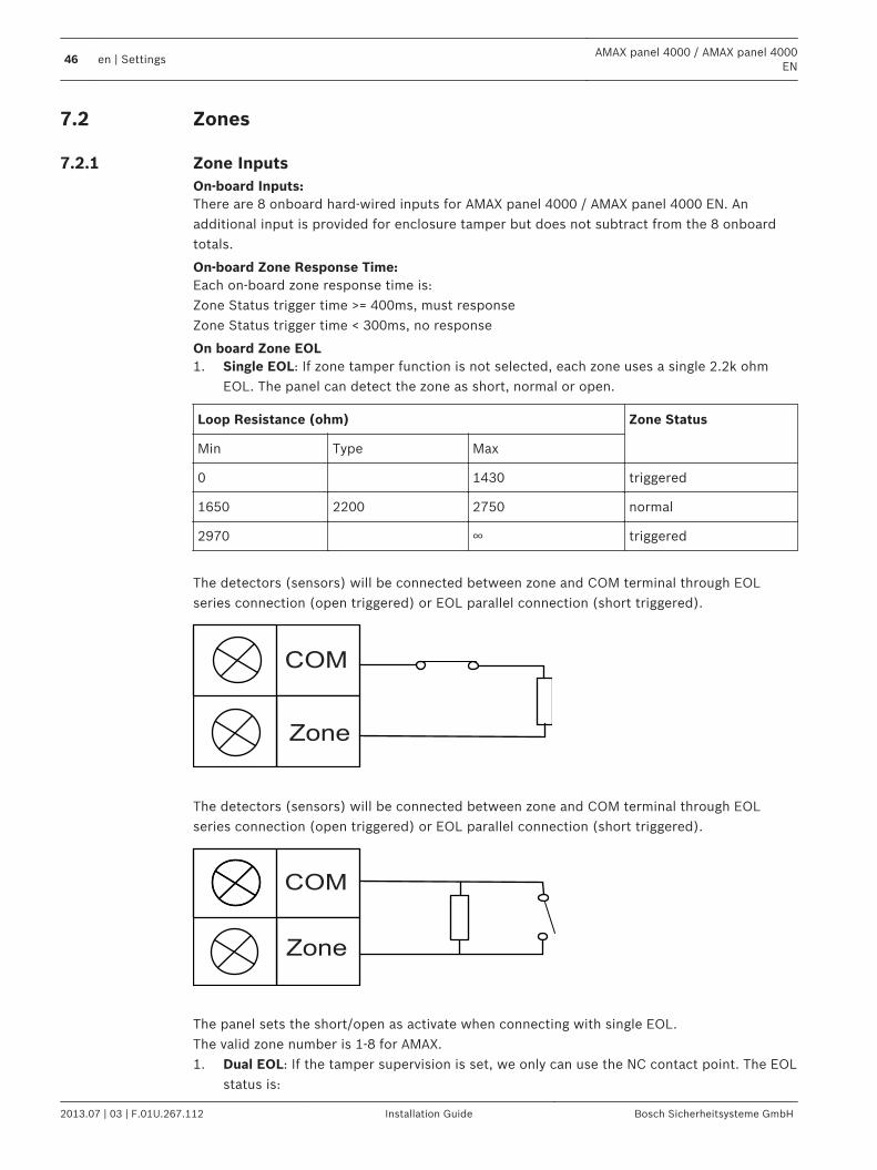
On board Zone EOL1. Single EOL: If zone tamper function is not selected, each zone uses a single 2.2k ohm
EOL. The panel can detect the zone as short, normal or open.
Loop Resistance (ohm) Zone Status
Min Type Max
0 1430 triggered
1650 2200 2750 normal
2970 ∞ triggered
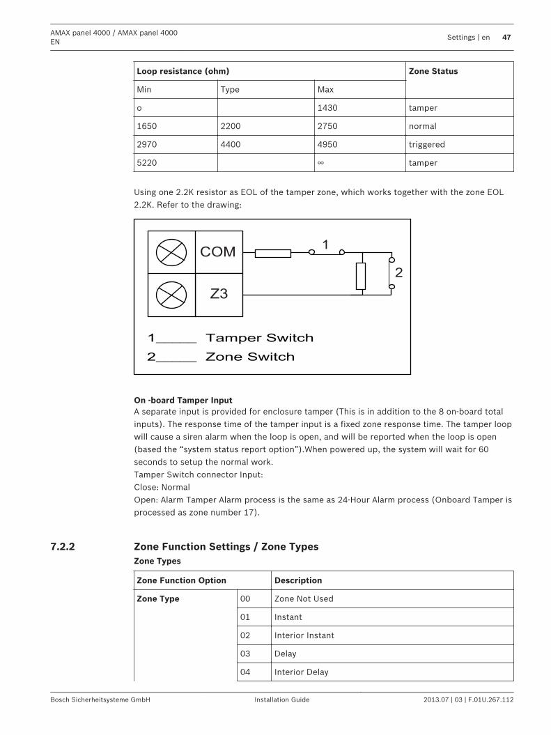
The detectors (sensors) will be connected between zone and COM terminal through EOLseries connection (open triggered) or EOL parallel connection (short triggered).
COM
Zone
The detectors (sensors) will be connected between zone and COM terminal through EOLseries connection (open triggered) or EOL parallel connection (short triggered).
COM
Zone
The panel sets the short/open as activate when connecting with single EOL.The valid zone number is 1-8 for AMAX.1. Dual EOL: If the tamper supervision is set, we only can use the NC contact point. The EOL
status is:
7.2
7.2.1
46 en | SettingsAMAX panel 4000 / AMAX panel 4000
EN
2013.07 | 03 | F.01U.267.112 Installation Guide Bosch Sicherheitsysteme GmbH
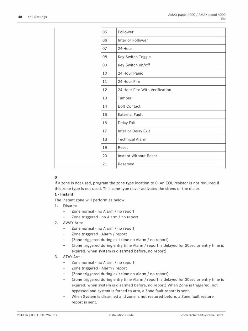
Loop resistance (ohm) Zone Status
Min Type Max
o 1430 tamper
1650 2200 2750 normal
2970 4400 4950 triggered
5220 ∞ tamper
Using one 2.2K resistor as EOL of the tamper zone, which works together with the zone EOL2.2K. Refer to the drawing:
COM
Z3
1
2
On -board Tamper InputA separate input is provided for enclosure tamper (This is in addition to the 8 on-board totalinputs). The response time of the tamper input is a fixed zone response time. The tamper loopwill cause a siren alarm when the loop is open, and will be reported when the loop is open(based the “system status report option”).When powered up, the system will wait for 60seconds to setup the normal work.Tamper Switch connector Input:Close: NormalOpen: Alarm Tamper Alarm process is the same as 24-Hour Alarm process (Onboard Tamper isprocessed as zone number 17).
Zone Function Settings / Zone TypesZone Types
Zone Function Option Description
Zone Type 00 Zone Not Used
01 Instant
02 Interior Instant
03 Delay
04 Interior Delay
7.2.2
AMAX panel 4000 / AMAX panel 4000EN
Settings | en 47
Bosch Sicherheitsysteme GmbH Installation Guide 2013.07 | 03 | F.01U.267.112
05 Follower
06 Interior Follower
07 24-Hour
08 Key-Switch Toggle
09 Key Switch on/off
10 24 Hour Panic
11 24 Hour Fire
12 24 Hour Fire With Verification
13 Tamper
14 Bolt Contact
15 External Fault
16 Delay Exit
17 Interior Delay Exit
18 Technical Alarm
19 Reset
20 Instant Without Reset
21 Reserved
0If a zone is not used, program the zone type location to 0. An EOL resistor is not required ifthis zone type is not used. This zone type never activates the sirens or the dialer.1 - InstantThe instant zone will perform as below:1. Disarm:
– Zone normal - no Alarm / no report– Zone triggered - no Alarm / no report
2. AWAY Arm:– Zone normal - no Alarm / no report– Zone triggered - Alarm / report– (Zone triggered during exit time no Alarm / no report)– (Zone triggered during entry time Alarm / report is delayed for 30sec or entry time is
expired, when system is disarmed before, no report)3. STAY Arm:
– Zone normal - no Alarm / no report– Zone triggered - Alarm / report– (Zone triggered during exit time no Alarm / no report)– (Zone triggered during entry time Alarm / report is delayed for 30sec or entry time is
expired, when system is disarmed before, no report) When Zone is triggered, notbypassed and system is forced to arm, a Zone fault report is sent.
– When System is disarmed and zone is not restored before, a Zone fault restorereport is sent.
48 en | SettingsAMAX panel 4000 / AMAX panel 4000
EN
2013.07 | 03 | F.01U.267.112 Installation Guide Bosch Sicherheitsysteme GmbH
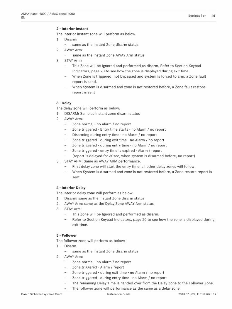
2 - Interior InstantThe interior instant zone will perform as below:1. Disarm:
– same as the Instant Zone disarm status2. AWAY Arm:
– same as the Instant Zone AWAY Arm status3. STAY Arm:
– This Zone will be Ignored and performed as disarm. Refer to Section KeypadIndicators, page 20 to see how the zone is displayed during exit time.
– When Zone is triggered, not bypassed and system is forced to arm, a Zone faultreport is send.
– When System is disarmed and zone is not restored before, a Zone fault restorereport is sent
3 - DelayThe delay zone will perform as below:1. DISARM: Same as Instant zone disarm status2. AWAY Arm:
– Zone normal - no Alarm / no report– Zone triggered - Entry time starts - no Alarm / no report– Disarming during entry time - no Alarm / no report– Zone triggered - during exit time - no Alarm / no report– Zone triggered - during entry time - no Alarm / no report– Zone triggered - entry time is expired - Alarm / report– (report is delayed for 30sec, when system is disarmed before, no report)
3. STAY ARM: Same as AWAY ARM performance.– First delay zone will start the entry time; all other delay zones will follow.– When System is disarmed and zone is not restored before, a Zone restore report is
sent. 4 - Interior DelayThe Interior delay zone will perform as below:1. Disarm: same as the Instant Zone disarm status2. AWAY Arm: same as the Delay Zone AWAY Arm status3. STAY Arm:
– This Zone will be Ignored and performed as disarm.– Refer to Section Keypad Indicators, page 20 to see how the zone is displayed during
exit time. 5 - FollowerThe follower zone will perform as below:1. Disarm:
– same as the Instant Zone disarm status2. AWAY Arm:
– Zone normal - no Alarm / no report– Zone triggered - Alarm / report– Zone triggered - during exit time - no Alarm / no report– Zone triggered - during entry time - no Alarm / no report– The remaining Delay Time is handed over from the Delay Zone to the Follower Zone.– The follower zone will performance as the same as a delay zone.
AMAX panel 4000 / AMAX panel 4000EN
Settings | en 49
Bosch Sicherheitsysteme GmbH Installation Guide 2013.07 | 03 | F.01U.267.112
– If there are two or more zones programmed as delay zones and both are triggered,the follower zone will follow the first triggered delay zone
3. STAY ARM: same as the delay zone. 6 - Interior FollowerThe interior follower zone will perform as below:1. Disarm: same as the Instant Zone disarm status2. AWAY Arm: same as the Follower Zone AWAY Arm status3. STAY Arm:
– This zone will be ignored and performed as disarm.– Refer to Section Keypad Indicators, page 20 to see how the zone is displayed during
exit time. 7 - 24 Hour ZoneThe 24 Hour zone will perform as below:1. Disarm:
– Zone normal - no Alarm / no report– Zone triggered - Alarm / report
2. AWAY Arm:– Zone normal - no Alarm / no report– Zone triggered - Alarm / report– Zone triggered - during exit time - Alarm / report– Zone triggered - during entry time - Alarm / report
3. STAY Arm: Same as AWAY Arm performance.– A 24 Hour zone does not send a restore report until the zone is restored.
8 - Tamper ZoneThe Tamper zone will perform as below:1. Disarm:
– Zone normal - no Alarm / no report– Zone triggered - Alarm / report
2. AWAY Arm:– Zone normal - no Alarm / no report– Zone triggered - Alarm / report– Zone triggered - during exit time - Alarm / report– Zone triggered - during entry time - Alarm / report
3. STAY Arm: Same as AWAY Arm performance.– A Tamper zone does not send a restore report until the zone is restored.
9 - Fire ZoneThe Fire zone will perform as below:1. Disarm:
– Zone normal - no Alarm / no report– Zone triggered - Alarm / report
2. AWAY Arm:– Zone normal - no Alarm / no report– Zone triggered - Alarm / report– Zone triggered - during exit time - Alarm / report– Zone triggered - during entry time - Alarm / report
3. STAY Arm: Same as AWAY Arm performance.
50 en | SettingsAMAX panel 4000 / AMAX panel 4000
EN
2013.07 | 03 | F.01U.267.112 Installation Guide Bosch Sicherheitsysteme GmbH
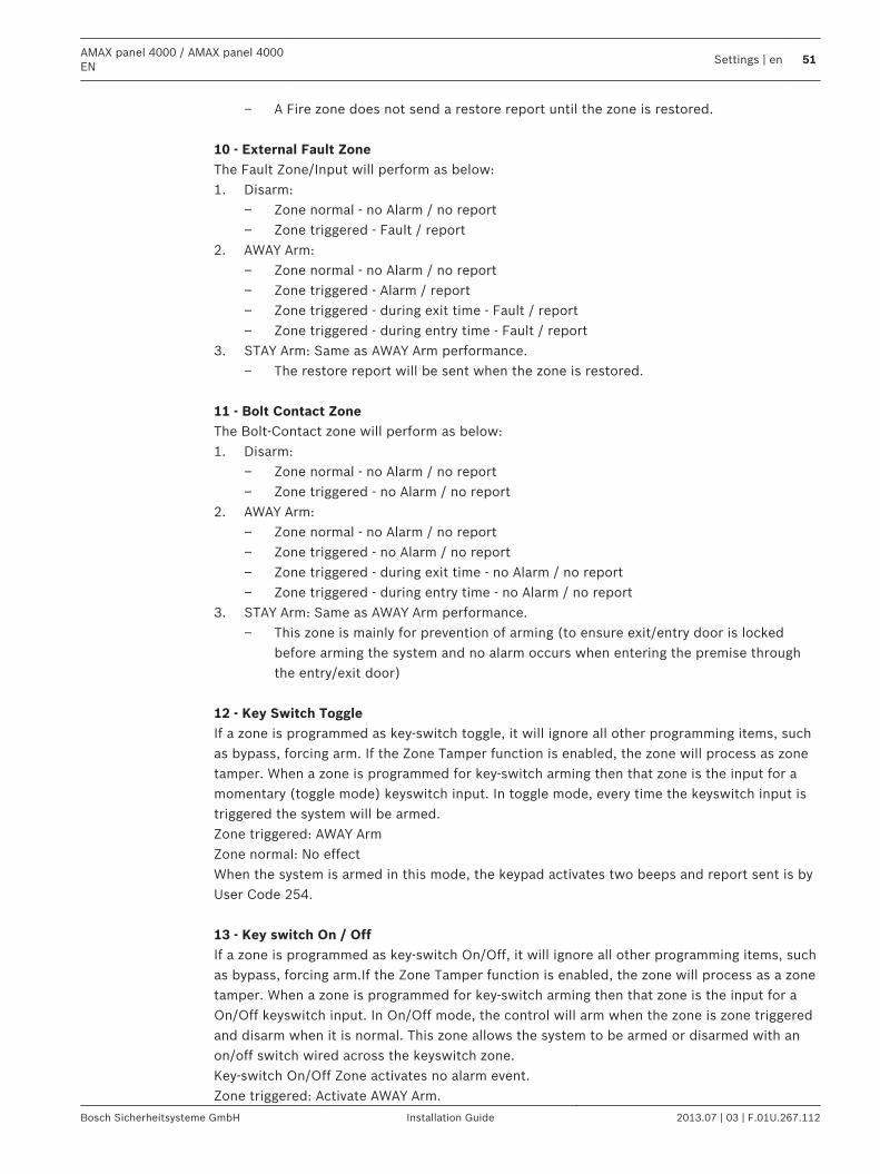
– A Fire zone does not send a restore report until the zone is restored. 10 - External Fault ZoneThe Fault Zone/Input will perform as below:1. Disarm:
– Zone normal - no Alarm / no report– Zone triggered - Fault / report
2. AWAY Arm:– Zone normal - no Alarm / no report– Zone triggered - Alarm / report– Zone triggered - during exit time - Fault / report– Zone triggered - during entry time - Fault / report
3. STAY Arm: Same as AWAY Arm performance.– The restore report will be sent when the zone is restored.
11 - Bolt Contact ZoneThe Bolt-Contact zone will perform as below:1. Disarm:
– Zone normal - no Alarm / no report– Zone triggered - no Alarm / no report
2. AWAY Arm:– Zone normal - no Alarm / no report– Zone triggered - no Alarm / no report– Zone triggered - during exit time - no Alarm / no report– Zone triggered - during entry time - no Alarm / no report
3. STAY Arm: Same as AWAY Arm performance.– This zone is mainly for prevention of arming (to ensure exit/entry door is locked
before arming the system and no alarm occurs when entering the premise throughthe entry/exit door)
12 - Key Switch ToggleIf a zone is programmed as key-switch toggle, it will ignore all other programming items, suchas bypass, forcing arm. If the Zone Tamper function is enabled, the zone will process as zonetamper. When a zone is programmed for key-switch arming then that zone is the input for amomentary (toggle mode) keyswitch input. In toggle mode, every time the keyswitch input istriggered the system will be armed.Zone triggered: AWAY ArmZone normal: No effectWhen the system is armed in this mode, the keypad activates two beeps and report sent is byUser Code 254. 13 - Key switch On / OffIf a zone is programmed as key-switch On/Off, it will ignore all other programming items, suchas bypass, forcing arm.If the Zone Tamper function is enabled, the zone will process as a zonetamper. When a zone is programmed for key-switch arming then that zone is the input for aOn/Off keyswitch input. In On/Off mode, the control will arm when the zone is zone triggeredand disarm when it is normal. This zone allows the system to be armed or disarmed with anon/off switch wired across the keyswitch zone.Key-switch On/Off Zone activates no alarm event.Zone triggered: Activate AWAY Arm.
AMAX panel 4000 / AMAX panel 4000EN
Settings | en 51
Bosch Sicherheitsysteme GmbH Installation Guide 2013.07 | 03 | F.01U.267.112
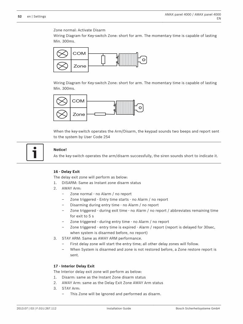
Zone normal: Activate DisarmWiring Diagram for Key-switch Zone: short for arm. The momentary time is capable of lastingMin. 300ms.
COM
Zone
Wiring Diagram for Key-switch Zone: short for arm. The momentary time is capable of lastingMin. 300ms.
COM
Zone
When the key-switch operates the Arm/Disarm, the keypad sounds two beeps and report sentto the system by User Code 254
Notice!
As the key-switch operates the arm/disarm successfully, the siren sounds short to indicate it.
16 - Delay ExitThe delay exit zone will perform as below:1. DISARM: Same as Instant zone disarm status2. AWAY Arm:
– Zone normal - no Alarm / no report– Zone triggered - Entry time starts - no Alarm / no report– Disarming during entry time - no Alarm / no report– Zone triggered - during exit time - no Alarm / no report / abbreviates remaining time
for exit to 5 s– Zone triggered - during entry time - no Alarm / no report– Zone triggered - entry time is expired - Alarm / report (report is delayed for 30sec,
when system is disarmed before, no report)3. STAY ARM: Same as AWAY ARM performance.
– First delay zone will start the entry time; all other delay zones will follow.– When System is disarmed and zone is not restored before, a Zone restore report is
sent. 17 - Interior Delay ExitThe Interior delay exit zone will perform as below:1. Disarm: same as the Instant Zone disarm status2. AWAY Arm: same as the Delay Exit Zone AWAY Arm status3. STAY Arm:
– This Zone will be Ignored and performed as disarm.
52 en | SettingsAMAX panel 4000 / AMAX panel 4000
EN
2013.07 | 03 | F.01U.267.112 Installation Guide Bosch Sicherheitsysteme GmbH
– Refer to Section Keypad Indicators, page 20 to see how the zone is displayed duringexit time.
18 - Technical AlarmThe Technical Alarm zone will perform as below:1. Disarm:
– Zone normal - no Alarm / no report– Zone triggered - Alarm / report
2. AWAY Arm:– Zone normal - no Alarm / no report– Zone triggered - Alarm / report– Zone triggered - during exit time - Alarm / report– Zone triggered - during entry time - Alarm / report
3. STAY Arm: Same as AWAY Arm performance.– A Technical zone does not send a restore report until the zone is restored.
19 - ResetThe Reset zone will perform as below:1. Disarm:
– Zone normal - no Alarm / no report– Zone triggered – performs system reset / no report
2. AWAY Arm:– Zone normal - no Alarm / no report
3. STAY Arm: Same as AWAY Arm performance. 20 - Instant ReportThe Instant report zone will perform as below:1. Disarm:
– Zone normal - no Alarm / no restore report– Zone triggered - no Alarm / no report
2. AWAY Arm:– Zone normal - no Alarm / no restore report– Zone triggered - no Alarm / sends report– Zone triggered - during exit time - Alarm / sends report– Zone triggered - during entry time - Alarm / sends report
3. STAY Arm: Same as AWAY Arm performance.
Zone Function Settings / Zone Options
Zone Function Option Description
Force Arm / Bypass 0 Disabled
1 Force Arm
2 Bypass
3 All
Silent Alarm / ChimeMode
0 Disabled
1 Silent Alarm
7.2.3
AMAX panel 4000 / AMAX panel 4000EN
Settings | en 53
Bosch Sicherheitsysteme GmbH Installation Guide 2013.07 | 03 | F.01U.267.112
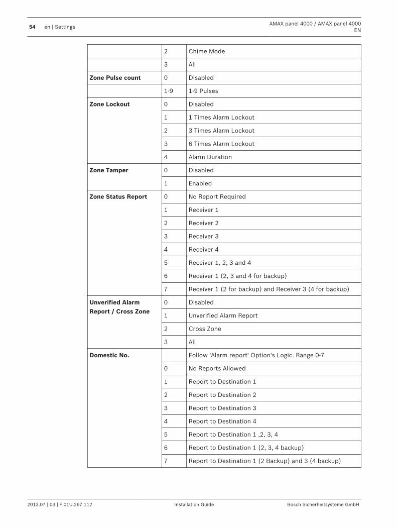
2 Chime Mode
3 All
Zone Pulse count 0 Disabled
1-9 1-9 Pulses
Zone Lockout 0 Disabled
1 1 Times Alarm Lockout
2 3 Times Alarm Lockout
3 6 Times Alarm Lockout
4 Alarm Duration
Zone Tamper 0 Disabled
1 Enabled
Zone Status Report 0 No Report Required
1 Receiver 1
2 Receiver 2
3 Receiver 3
4 Receiver 4
5 Receiver 1, 2, 3 and 4
6 Receiver 1 (2, 3 and 4 for backup)
7 Receiver 1 (2 for backup) and Receiver 3 (4 for backup)
Unverified AlarmReport / Cross Zone
0 Disabled
1 Unverified Alarm Report
2 Cross Zone
3 All
Domestic No. Follow 'Alarm report' Option's Logic. Range 0-7
0 No Reports Allowed
1 Report to Destination 1
2 Report to Destination 2
3 Report to Destination 3
4 Report to Destination 4
5 Report to Destination 1 ,2, 3, 4
6 Report to Destination 1 (2, 3, 4 backup)
7 Report to Destination 1 (2 Backup) and 3 (4 backup)
54 en | SettingsAMAX panel 4000 / AMAX panel 4000
EN
2013.07 | 03 | F.01U.267.112 Installation Guide Bosch Sicherheitsysteme GmbH
Zone BypassIf this option is enabled, the operator can bypass zones before arming the system. If thisoption is disabled, manual bypass of the zone will not be available. After manual bypass of thezone, a zone bypass report will be sent.The zone bypass is valid in one arming period only and will be resumed after disarming. Beforedisarming, the bypassed zones will ignore all zone triggering and restoration events.The key switch zone cannot be bypassed.
Forced ArmingIf this option is selected, the system can be armed when the zone is in triggering status. If thisoption is not selected, the system will not allow the PIN holder to arm the system unless thezone with problems has resumed to normal status or been manually bypassed.The arming with a zone in triggering status is called forced arming.When the operating system arms:– When the keypad or key switch zone is used to execute system arming, the system will
show the zone status at first. If a zone in triggering status is not bypassed and the forcedarming option is in disabled status, it cannot be successfully armed.
– When the keypad or key switch zone is used to execute system arming, the system willshow the zone status at first. If a zone in triggering status is not bypassed and the forcedarming option is in enabled status, the system will be successfully armed. If the zone isstill not recovered at the end of the exit delay time, the system will show the fault reportof the zone.
– When the fault is recovered, a zone recovery report will be sent.The exceptions to forced arming option:– In telephone and programming software remote arming, forced arming is available no
matter the zone is programmed as enabled or disabled forced arming.
Silent AlarmEnabling this option can set the zone to mute alarm. Silent alarm will not trigger the output ofkeypad buzzer and the output of the type of event of system audio alarm, but can trigger theoutput of the type of event of system alarm (both sound and silent) and the alarm event canstill be transmitted according to programming path.
Zone LockingThe zone locking option of each zone can be set to a non-locking, 1 time of alarm locking, 3times of alarm locking, 6 times of alarm locking and follow alarm time.For unlocking, set the zone locking option to 0 to disable the zone locking function.3 times of alarm lockingIf the locking option is set to 2, the zone can only transmit up to 3 times of alarm report ineach arming period. After zone re-disarming re-arming, the locking count will be reset.The alarm control panel will process locking according to the following logic:1. When the zone or zone tamper is trigger and siren alarm is resulted, within the period of
alarm output time, the alarm control panel will ignore the status detection of the zone.2. When the alarms reach 3 times, the zone will be locked.3. If alarm occurs in the locked zone, the zone will send zone fault report.4. Before the end of the alarm output time, ten zone recovery event will not be transmitted.5. If the zone locking option is disabled, the times of alarms will not be restrained. Even
when other zones are locked, that zone can still generate alarm.6 times of alarm lockingSimilar to 3 times of alarm locking, with alarm limited to not more than 6 times.
AMAX panel 4000 / AMAX panel 4000EN
Settings | en 55
Bosch Sicherheitsysteme GmbH Installation Guide 2013.07 | 03 | F.01U.267.112
Locking within the period of alarm output time. Repeating the process of alarm locking in theperiod of alarm output time, without limit to times.
Zone TamperThe system supports the tamper detection of the zone. This function ensures that the zone isin normal operating status. The process is as follows:1. If 24-hour zone tamper is enabled, the wiring method for two-terminal resistor is
required.2. If the zone detects that the 24-hour tamper is triggered, the zone tamper alarm will be
processed the same as 24-hour zone.3. If the zone detests zone alarm, the zone will process according to specified zone type.If the zone is programmed to disable 24-hour zone tamper, the wiring method for single-terminal resistor is required. If the zone detests alarm, the zone will process according tospecified zone type.
Zone Status ReportingThe alarm control panel reports zone status according to the specified path, including alarm,zone fault, zone bypass and zone tamper alarm.
Zone Chime ModeThe system will support the chime mode.The process is as follows:– If the chime mode is used and a zone is triggered the keypad buzzer will sound for 1
second (only in disarmed status)
Zone Pulse countThe system will support the pulse count mode.The process is as follows:– pulse count duration time must be configured (Refer to chapter 9.1 Communication and
Report Settings)– pulse count for a zone can be set to a value between 1 and 9 (0 = disabled)The process is as follows:– an alarm is only created, if the zone is triggered as many times as the value “pulse count”
within the time “count duration”.
Domestic No.The system will support the domestic call mode.The process is as follows:– If the domestic call mode is configured for a zone and an alarm from this zone is created
the alarm will be reported to the destination(s) configured and needs acknowledgement.
Cross ZoneThe cross zone option works as follows:Prerequisites:– At least two zones in the same area have option Cross Zone enabled– System option Cross Zone Timer is set to a value higher than 0When one of these zones is triggered for more than 20 seconds, an alarm is created.When one of these zones (the first zone) is triggered for a shorter time than 20 seconds, thecross zone timer starts, no alarm is created at this time.
56 en | SettingsAMAX panel 4000 / AMAX panel 4000
EN
2013.07 | 03 | F.01U.267.112 Installation Guide Bosch Sicherheitsysteme GmbH
– When no more zones (with cross zone option) are triggered within the cross zone time,no alarm is created.
– When the first zone is triggered twice or more within the cross zone time, no alarm iscreated.
– When a second zone or further zones (with cross zone option) is/are triggered within thecross zone time, then an alarm is created for all triggered zones.
– When the first zone or one of the other zones (with cross zone option) is/are triggeredtwice or more after cross zone time is expired, the timer restarts.
Unverified Alarm ReportEnables/disables option Unverified Alarm Report. When a cross zone is triggered, but no alarmis created, system creates an unverified alarm in order to report. System reports unverifiedalarms if option Unverified Alarm Report is enabled.
Adding and Changing ZoneBased on zone numbers, when adding or changing each zone, it is required to specify its area,select the zone functions and select the module of zone source.When the zone is selected to 0, i.e., the zone is not used, any addresses set on the zonefunction and module selection are invalid.
Zone Indication Keypad and Event LogZones may be indicated on keypads and in event logs with a number that are different fromzone number used for programming and hardware input.
One area systemZones are indicated on keypads according to the zone numbers. When disable one zone theindication number of all following (higher) zone numbers will shift to a value decreased byone.
Multi area systemOnly zones assigned to one area are indicated on an area keypad in the order beginning with 1and by following the order of zone numbers.
Examples:In a one are system keypad zone number 17 should be indicated on a 16 zone LED keypad.After disabling zone 16 (or another one in range 1 to 16) zone number 17 is indicated onkeypad as number 16.
7.2.4
7.2.5
AMAX panel 4000 / AMAX panel 4000EN
Settings | en 57
Bosch Sicherheitsysteme GmbH Installation Guide 2013.07 | 03 | F.01U.267.112
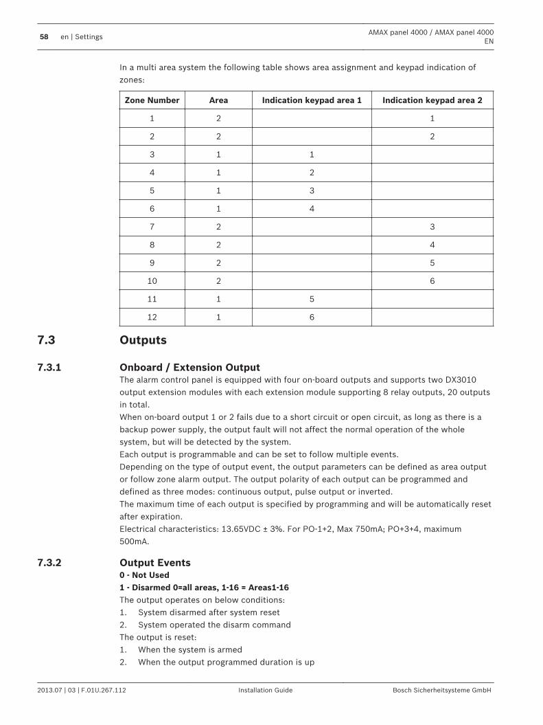
In a multi area system the following table shows area assignment and keypad indication ofzones:
Zone Number Area Indication keypad area 1 Indication keypad area 2
1 2 1
2 2 2
3 1 1
4 1 2
5 1 3
6 1 4
7 2 3
8 2 4
9 2 5
10 2 6
11 1 5
12 1 6
Outputs
Onboard / Extension OutputThe alarm control panel is equipped with four on-board outputs and supports two DX3010output extension modules with each extension module supporting 8 relay outputs, 20 outputsin total.When on-board output 1 or 2 fails due to a short circuit or open circuit, as long as there is abackup power supply, the output fault will not affect the normal operation of the wholesystem, but will be detected by the system.Each output is programmable and can be set to follow multiple events.Depending on the type of output event, the output parameters can be defined as area outputor follow zone alarm output. The output polarity of each output can be programmed anddefined as three modes: continuous output, pulse output or inverted.The maximum time of each output is specified by programming and will be automatically resetafter expiration.Electrical characteristics: 13.65VDC ± 3%. For PO-1+2, Max 750mA; PO+3+4, maximum500mA.
Output Events0 - Not Used1 - Disarmed 0=all areas, 1-16 = Areas1-16The output operates on below conditions:1. System disarmed after system reset2. System operated the disarm commandThe output is reset:1. When the system is armed2. When the output programmed duration is up
7.3
7.3.1
7.3.2
58 en | SettingsAMAX panel 4000 / AMAX panel 4000
EN
2013.07 | 03 | F.01U.267.112 Installation Guide Bosch Sicherheitsysteme GmbH
2 - System Armed 0=all areas, 1-16 = Areas1-16The output operates on below conditions:1. System armed after system resetSystem operated the arm command and until system is armed. (When system is operating thearm command, the system will arm after the exit delay time is up.)The output is reset:1. When the system is disarmed2. When the output programmed duration is up.If this duration is programmed as 000, the output will continue till the system disarmed. 3 - System AlarmThis output operates when an alarm occurs.The output is reset:1. When the system is disarmed and alarm is reset.2. When the output programmed duration is up.When a new alarm occurred, the alarm will reset the alarm time.If this duration is programmed as 000, the output will continue till the zone restore or systemdisarmed. 4 - System Alarm (audile and silent)In case of audio alarm of the system, the output will be enabled.– Zone (alarm or tamper) programmed to disable zone silent alarm.– System tamper / DX2010 tamper/keypad tamper.– Keypad alarm (emergency alarm, fire alarm, medical aid alarm)Or in case of silent alarm of the system, the output will be enabled.– Zone (alarm or tamper) programmed to enable zone silent alarm. In case of following
conditions, the output will be reset.– Alarm reset.– Arming of the system.– Disarming of the system.In case of new alarm event, the output time will be reset and re-timed.When the output time is set to 000 and the alarm siren sounds for 0, the output will continueuntil reset of alarm output or disarming of the system by the command of [PIN] [3] [2] [#].The output of the following system alarm is only 1 second:– Alarm siren test.– Pacing (tamper/alarm/reset).– Key switch arming or- locking key switch disarming. 5 - External AWAY SirenThe output is triggered when:System is AWAY armed +zone intruder alarm (intruder alarm = instant / interior instant /delay / interior delay / delay exit / interior delay exit / follower / interior follower / 24h (can besilenced) / Fire (can be silenced) / Technical Alarm (can be silenced))System is AWAY armed +tamper alarm(no alarm when panel is disarmed) 6 - External STAY SirenThe output is triggered when:
AMAX panel 4000 / AMAX panel 4000EN
Settings | en 59
Bosch Sicherheitsysteme GmbH Installation Guide 2013.07 | 03 | F.01U.267.112
System is STAY armed +zone intruder alarm (intruder alarm = instant / interior instant / delay /interior delay / delay exit / interior delay exit / follower / interior follower / 24h (can besilenced) / Fire (can be silenced) / Technical Alarm (can be silenced))System is STAY armed +tamper alarm(no alarm when panel is disarmed) 7 - Internal SirenThe output is triggered when:System is AWAY armed +zone intruder alarm (intruder alarm = instant / interior instant /delay / interior delay / delay exit / interior delay exit / follower / interior follower / 24h (can besilenced) / Fire (can be silenced) / Technical Alarm (can be silenced))System is AWAY armed +tamper alarmSystem is STAY armed +zone intruder alarm (intruder alarm = instant / interior instant / delay /interior delay / delay exit / interior delay exit / follower / interior follower / 24h (can besilenced) / Fire (can be silenced) / Technical Alarm (can be silenced))System is AWAY armed +tamper alarmSystem is disarmed +zone tamper alarmWhen panel is armed = one pulse activation (1sec) (enabled/disable option can be combinedwith disarm)When panel is disarmed = two pulse activation (1sec) (enabled/disable option can becombined with arm)When Programming mode is entered = one pulse activation (1sec) (enabled/disable option) 8 - Internal Siren with tamperThe output is triggered when Internal Siren with tamper. 9 - Entry/Exit Delay WarningEntry Delay WarningThis output operates during Entry Time.The output is reset:1. When the system disarmed2. When Entry Time expires3. When the output programmed duration is up.Exit Delay WarningThis output operates during Exit Time when the control panel is armed.The output is reset:1. When the system is disarmed2. When Exit Time expires3. When the output programmed duration is up.If this duration is programmed as 000, the output will continue till the delay warning durationis up. 10 - Telephone Line FaultThis output operates when a telephone line fault occurs.The output is reset:1. When the Telephone line is restored and fault is reset.2. When the output programmed duration is up.If this duration is programmed as 000, the output will continue till the telephone line isrestored and fault is reset.
60 en | SettingsAMAX panel 4000 / AMAX panel 4000
EN
2013.07 | 03 | F.01U.267.112 Installation Guide Bosch Sicherheitsysteme GmbH
11 - AC Power Supply FaultThis output operates when a AC MAINS fault occurs.The output is reset:1. When the AC power supply is restored and fault is reset.2. When the output programmed duration is up.If this duration is programmed as 000, the output will continue till the AC MAINS power isrestored and fault is reset. 12 - Low BatteryThis output operates when a Low Battery fault occurs.The Dynamic Battery Test is performed every 4 hours after the system is powered up andevery time the system is armed.The output is reset:1. Only after a Dynamic Battery Test report that the backup battery voltage is normal and
fault is reset.2. When the output programmed duration is up.If this duration is programmed as 000, the output will continue till battery is restored and faultis reset. 13 - TamperThis output operates when a Tamper condition occurs.The output is reset:1. When the output programmed duration is up.lf this duration is programmed as 000, the output will continue till the Tamper condition isRestored and Tamper is reset. 14 - External FaultThis output operates when an External Fault occurs.The output is reset:1. When the output programmed duration is up.lf this duration is programmed as 000, the output will continue till the External Fault isRestored and the fault is reset. 15 - All FaultsThis output operates when a Fault occurs.The output is reset:1. When the output programmed duration is up.lf this duration is programmed as 000, the output will continue till the Fault is Restored andthe fault is reset. 16 - Fire AlarmThe output is triggered when Fire Alarm. 17 - Fire ResetThe output is triggered when Fire Reset. 18 - AWAY ArmedThis output operates when System is AWAY Armed.The output is reset:1. When the output programmed duration is up.
AMAX panel 4000 / AMAX panel 4000EN
Settings | en 61
Bosch Sicherheitsysteme GmbH Installation Guide 2013.07 | 03 | F.01U.267.112
lf this duration is programmed as 000, the output will continue till the System is Disarmed. 19 - STAY ArmedThis output operates when System is STAY Armed.The output is reset:1. When the output programmed duration is up.lf this duration is programmed as 000, the output will continue till the System is Disarmed. 20 - ResetThis output operates when a reset is performed in the system. 21 - Follow Zone Event Zone NumberThe output follow type imitates the zone alarm state, when alarm or tamper is generated inthe corresponding zone, the output will be enabled. When system arming, disarming or outputtime ends, the output will be reset.For actual output time, See Table The Value Ranges of Output Programming Options, page 125 22 - RF Keyfob button 3The output is triggered when Keyfob Button 3 is pressed. 23 - RF Keyfob button 4The output is triggered when Keyfob Button 4 is pressed. 24 - Chime IndicationThe output is triggered when Chime Indication. 25 - Verified AlarmThe output is triggered when Verified Alarm. 26 - Unverified AlarmThe output is triggered when Unverified Alarm. 27 - Technical AlarmThe output is triggered when Technical Alarm. 28 - Bypassed ZoneThe output is triggered when Bypassed Zone. 29 - Ready to ArmThe output is triggered when ready to arm. 30 – Walk Test Output ModeThe output is triggered when Walk Test Output Mode.
62 en | SettingsAMAX panel 4000 / AMAX panel 4000
EN
2013.07 | 03 | F.01U.267.112 Installation Guide Bosch Sicherheitsysteme GmbH
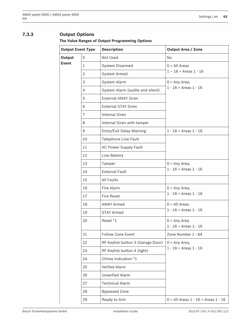
Output OptionsThe Value Ranges of Output Programming Options
Output Event Type Description Output Area / Zone
OutputEvent
0 Not Used No
1 System Disarmed 0 = All Areas1 – 16 = Areas 1 - 16
2 System Armed
3 System Alarm 0 = Any Area,1 - 16 = Areas 1 - 16
4 System Alarm (audile and silent)
5 External AWAY Siren
6 External STAY Siren
7 Internal Siren
8 Internal Siren with tamper
9 Entry/Exit Delay Warning 1 - 16 = Areas 1 - 16
10 Telephone Line Fault
11 AC Power Supply Fault
12 Low Battery
13 Tamper 0 = Any Area,1 - 16 = Areas 1 - 16
14 External Fault
15 All Faults
16 Fire Alarm 0 = Any Area,1 - 16 = Areas 1 - 16
17 Fire Reset
18 AWAY Armed 0 = All Areas1 - 16 = Areas 1 - 16
19 STAY Armed
20 Reset *1 0 = Any Area1 - 16 = Areas 1 - 16
21 Follow Zone Event Zone Number 1 - 64
22 RF Keyfob button 3 (Garage Door) 0 = Any Area,1 - 16 = Areas 1 - 16
23 RF Keyfob button 4 (light)
24 Chime Indication *1
25 Verfied Alarm
26 Unverfied Alarm
27 Technical Alarm
28 Bypassed Zone
29 Ready to Arm 0 = All Areas 1 - 16 = Areas 1 - 16
7.3.3
AMAX panel 4000 / AMAX panel 4000EN
Settings | en 63
Bosch Sicherheitsysteme GmbH Installation Guide 2013.07 | 03 | F.01U.267.112
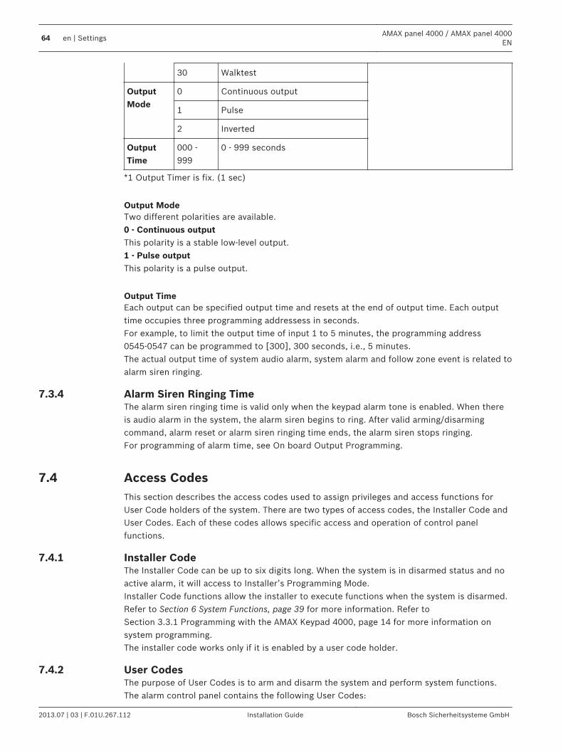
30 Walktest
OutputMode
0 Continuous output
1 Pulse
2 Inverted
OutputTime
000 -999
0 - 999 seconds
*1 Output Timer is fix. (1 sec)
Output ModeTwo different polarities are available.0 - Continuous outputThis polarity is a stable low-level output.1 - Pulse outputThis polarity is a pulse output.
Output TimeEach output can be specified output time and resets at the end of output time. Each outputtime occupies three programming addressess in seconds.For example, to limit the output time of input 1 to 5 minutes, the programming address0545-0547 can be programmed to [300], 300 seconds, i.e., 5 minutes.The actual output time of system audio alarm, system alarm and follow zone event is related toalarm siren ringing.
Alarm Siren Ringing TimeThe alarm siren ringing time is valid only when the keypad alarm tone is enabled. When thereis audio alarm in the system, the alarm siren begins to ring. After valid arming/disarmingcommand, alarm reset or alarm siren ringing time ends, the alarm siren stops ringing.For programming of alarm time, see On board Output Programming.
Access CodesThis section describes the access codes used to assign privileges and access functions forUser Code holders of the system. There are two types of access codes, the Installer Code andUser Codes. Each of these codes allows specific access and operation of control panelfunctions.
Installer CodeThe Installer Code can be up to six digits long. When the system is in disarmed status and noactive alarm, it will access to Installer’s Programming Mode.Installer Code functions allow the installer to execute functions when the system is disarmed.Refer to Section 6 System Functions, page 39 for more information. Refer toSection 3.3.1 Programming with the AMAX Keypad 4000, page 14 for more information onsystem programming.The installer code works only if it is enabled by a user code holder.
User Codes The purpose of User Codes is to arm and disarm the system and perform system functions.The alarm control panel contains the following User Codes:
7.3.4
7.4
7.4.1
7.4.2
64 en | SettingsAMAX panel 4000 / AMAX panel 4000
EN
2013.07 | 03 | F.01U.267.112 Installation Guide Bosch Sicherheitsysteme GmbH
Keypad User Codes #1 to #64 (reported 1 to 64)Key Fob User Codes *1 to *128 (reported 65 to 192)User Codes for special purpose:Use User Code 254 to send report when arming/disarming the system by key-switch user.Use User Code 253 to send report when arming the system in AWAY Mode or STAY Mode bykeypad single button.Use User Code 252 to send report when remotely arming the system by telephone call.Use User Code 251 to send report when remotely arming the system by A-Link Plus software.User Code can be four to six digits long. Each User Code should get assignment to area(s) andto an authority level.
System Settings - GeneralThis chapter describes eight categories of system settings including the system date and time,telephone settings, etc.
Installer Access Until Next ArmingBefore using installer access, a standard user has to enable installer access first. If optionInstaller Access Until Next Arming is enabled, installer access permission is limited to nextarming.
Force Arm When System Is In Trouble ConditionIf option Force Arm When System Is In Trouble Condition is enabled, an area can be forcearmed however there is trouble condition.
Siren / PO-1+PO-2 SupervisionIf option is enabled, system supervises whether siren is shortened or disconnected.
Keypad 2 Button AlarmIf option Keypad 2 Button Alarm is enabled, the following alarms can be sent by pressing andhold two keypad buttons simultaneously.Emergency alarm will be transmitted, if simultaneously [1] and [3] or [*] and [#] is pressedand hold.Fire alarm will be transmitted, if simultaneously [4] and [6] is pressed and hold.Silent keypad emergency medical alarm will be transmitted, if simultaneously [7] and [9] ispressed and hold.
Phone Line MonitorIf option Phone Line Monitor is enabled, system supervises whether phone line is broken ordisconnected.
Beep For Warning DevicesEnables/disables Beep For Warning Devices when the system is armed, disarmed or duringWalk Test.
Silence Warning Device When DisarmedEnables/disables Silence Warning Device when disarmed or by pressing any key.
7.5
7.5.1
7.5.2
7.5.3
7.5.4
7.5.5
7.5.6
7.5.7
AMAX panel 4000 / AMAX panel 4000EN
Settings | en 65
Bosch Sicherheitsysteme GmbH Installation Guide 2013.07 | 03 | F.01U.267.112
Event Record Count per Set/Unset PeriodOption Event Record Count per Set/Unset Period defines the maximum number of records foran event within the set/unset period.
System Tamper Indication In AreaOption System Tamper Indication In Area configures system where system tamper event isindicated. System tamper indication can be assigned to either the area where Zone 1 islocated in or to all Areas.
Internal Siren Beep As IndicationEnables or disables Internal Siren Beep as Indication when the system is armed, disarmed orprogramming mode is entered.
Battery Check IntervalOption Battery Check Interval defines the time interval in which the battery test is carried out.Also battery test is carried out when armed or when system power up.
Cross Zone TimerOption Cross Zone Timer defines time interval for the cross zone feature.
AC Power Supply Fault Report DelayAC Power Supply Fault is reported with configurable delay time. Option AC Power SupplyFault Report Delay defines delay time.
Date and TimeThe alarm control panel has a 24-hour clock and a 12-month calendar that need to be setduring installation. The order is year, month, day, hour and minute, with each item occupyingtwo digits [YY] [MM] [DD] [HH] [MM].For more information about date and time settings, see Date and Time Settings .
Fault InquiryFault and tamper conditions
7.5.8
7.5.9
7.5.10
7.5.11
7.5.12
7.5.13
7.5.14
7.5.15
66 en | SettingsAMAX panel 4000 / AMAX panel 4000
EN
2013.07 | 03 | F.01U.267.112 Installation Guide Bosch Sicherheitsysteme GmbH
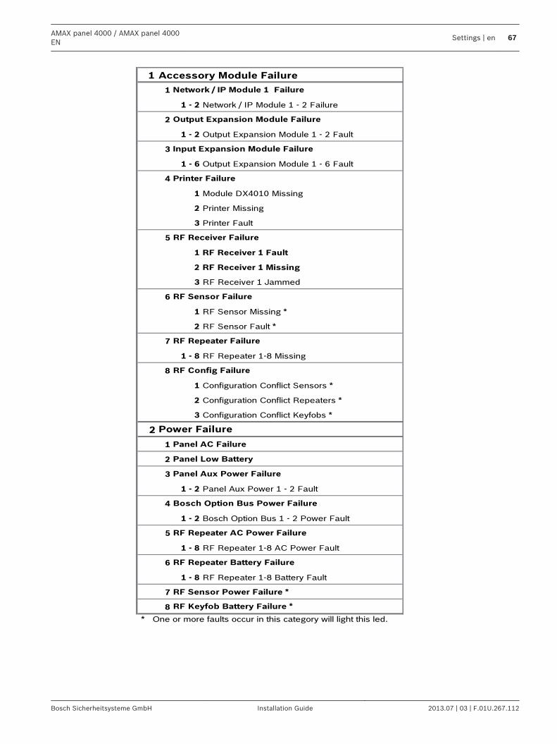
1 Accessory Module Failure
1
1 - 2 Network / IP Module 1 - 2 Failure
2
1 - 2 Output Expansion Module 1 - 2 Fault
3
1 - 6 Output Expansion Module 1 - 6 Fault
4
1 Module DX4010 Missing
2 Printer Missing
3 Printer Fault
5
1 RF Receiver 1 Fault
2 RF Receiver 1 Missing
3 RF Receiver 1 Jammed
6
1 RF Sensor Missing *
2 RF Sensor Fault *
7
1 - 8 RF Repeater 1-8 Missing
8
1 Configuration Conflict Sensors *
2 Configuration Conflict Repeaters *
3 Configuration Conflict Keyfobs *
2
1
2
3
1 - 2 Panel Aux Power 1 - 2 Fault
4
1 - 2 Bosch Option Bus 1 - 2 Power Fault
5
1 - 8 RF Repeater 1-8 AC Power Fault
6
1 - 8 RF Repeater 1-8 Battery Fault
7
8
* One or more faults occur in this category will light this led.
Network / IP Module 1 Failure
Output Expansion Module Failure
RF Config Failure
RF Repeater Failure
RF Sensor Failure
RF Receiver Failure
Printer Failure
Input Expansion Module Failure
RF Repeater Battery Failure
RF Sensor Power Failure *
RF Keyfob Battery Failure *
Power Failure
Panel AC Failure
Panel Low Battery
Panel Aux Power Failure
Bosch Option Bus Power Failure
RF Repeater AC Power Failure
AMAX panel 4000 / AMAX panel 4000EN
Settings | en 67
Bosch Sicherheitsysteme GmbH Installation Guide 2013.07 | 03 | F.01U.267.112
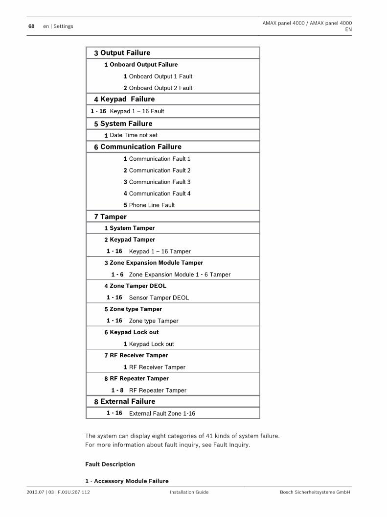
3
1
1 Onboard Output 1 Fault
2 Onboard Output 2 Fault
4
5
1
6
1 Communication Fault 1
2 Communication Fault 2
3 Communication Fault 3
4 Communication Fault 4
5 Phone Line Fault
7 Tamper
1
2
Keypad 1 – 16 Tamper
3
1 - 6 Zone Expansion Module 1 - 6 Tamper
4
Sensor Tamper DEOL
5
Zone type Tamper
6
1 Keypad Lock out
7
1 RF Receiver Tamper
8
1 - 8 RF Repeater Tamper
8
External Fault Zone 1-16
Keypad Failure
System Failure
Communication Failure
Onboard Output Failure
Keypad 1 – 16 Fault
Date Time not set
1 - 16
1 - 16
1 - 16
1 - 16
Output Failure
Keypad Tamper
System Tamper
1 - 16
External Failure
Zone Expansion Module Tamper
Zone Tamper DEOL
Zone type Tamper
Keypad Lock out
RF Receiver Tamper
RF Repeater Tamper
The system can display eight categories of 41 kinds of system failure.For more information about fault inquiry, see Fault Inquiry.
Fault Description 1 - Accessory Module Failure
68 en | SettingsAMAX panel 4000 / AMAX panel 4000
EN
2013.07 | 03 | F.01U.267.112 Installation Guide Bosch Sicherheitsysteme GmbH
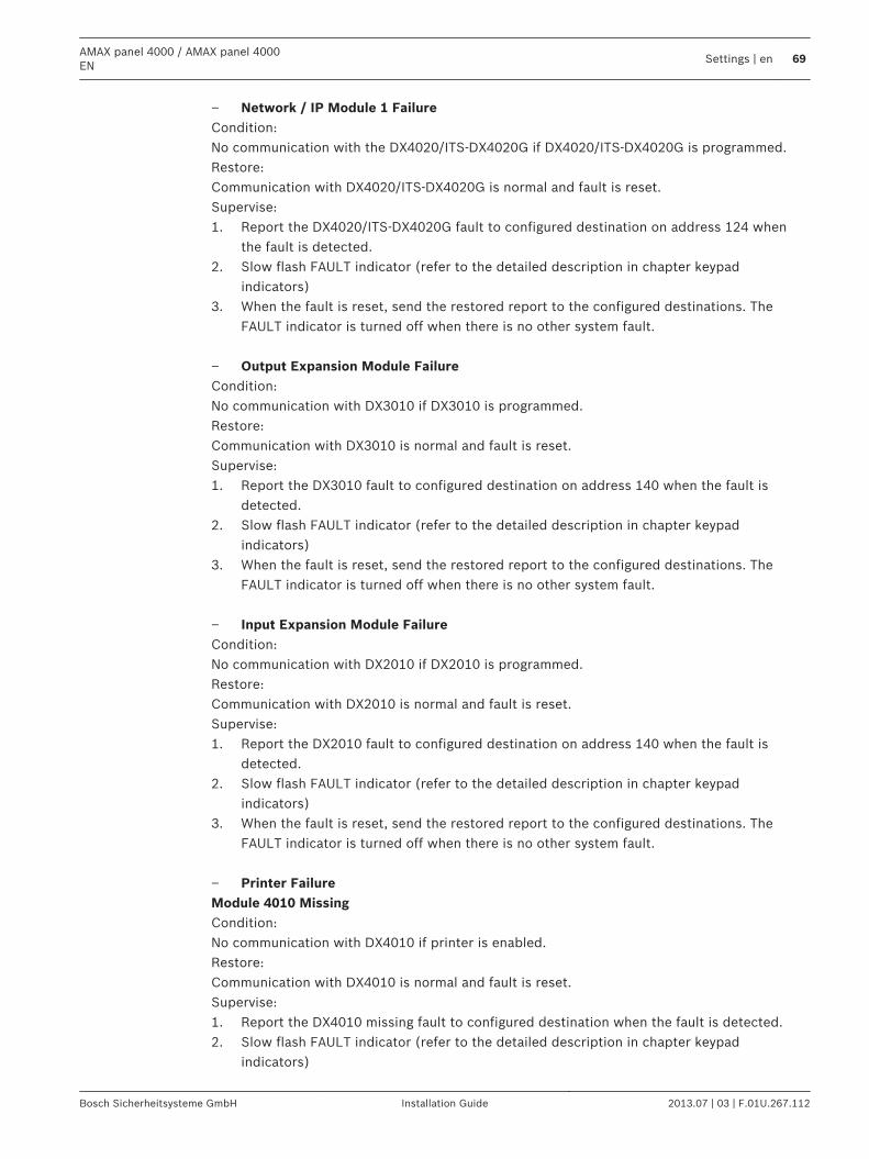
– Network / IP Module 1 FailureCondition:No communication with the DX4020/ITS-DX4020G if DX4020/ITS-DX4020G is programmed.Restore:Communication with DX4020/ITS-DX4020G is normal and fault is reset.Supervise:1. Report the DX4020/ITS-DX4020G fault to configured destination on address 124 when
the fault is detected.2. Slow flash FAULT indicator (refer to the detailed description in chapter keypad
indicators)3. When the fault is reset, send the restored report to the configured destinations. The
FAULT indicator is turned off when there is no other system fault. – Output Expansion Module FailureCondition:No communication with DX3010 if DX3010 is programmed.Restore:Communication with DX3010 is normal and fault is reset.Supervise:1. Report the DX3010 fault to configured destination on address 140 when the fault is
detected.2. Slow flash FAULT indicator (refer to the detailed description in chapter keypad
indicators)3. When the fault is reset, send the restored report to the configured destinations. The
FAULT indicator is turned off when there is no other system fault. – Input Expansion Module FailureCondition:No communication with DX2010 if DX2010 is programmed.Restore:Communication with DX2010 is normal and fault is reset.Supervise:1. Report the DX2010 fault to configured destination on address 140 when the fault is
detected.2. Slow flash FAULT indicator (refer to the detailed description in chapter keypad
indicators)3. When the fault is reset, send the restored report to the configured destinations. The
FAULT indicator is turned off when there is no other system fault. – Printer FailureModule 4010 MissingCondition:No communication with DX4010 if printer is enabled.Restore:Communication with DX4010 is normal and fault is reset.Supervise:1. Report the DX4010 missing fault to configured destination when the fault is detected.2. Slow flash FAULT indicator (refer to the detailed description in chapter keypad
indicators)
AMAX panel 4000 / AMAX panel 4000EN
Settings | en 69
Bosch Sicherheitsysteme GmbH Installation Guide 2013.07 | 03 | F.01U.267.112
3. When the fault is reset, send the restored report to the configured destinations. TheFAULT indicator is turned off when there is no other system fault.
Printer MissingCondition:No communication with printer if printer is enabled and the DX4010 is normal.Restore:Communication with printer and DX4010 are normal and fault is reset.Supervise:1. Report the printer missing fault to configured destination when the fault is detected.2. Slow flash FAULT indicator (refer to the detailed description in chapter keypad
indicators)3. When the fault is reset, send the restored report to the configured destinations. The
FAULT indicator is turned off when there is no other system fault.Printer FaultCondition:The printer is abnormal (e.g. printer no paper/printer buffer is overflow/...) if printer is enableand the DX4010 is normal.Restore:The printer and DX4010 are normal and fault is reset.Supervise:1. Report the printer error to configured destination when the fault is detected.2. Slow flash FAULT indicator (refer to the detailed description in chapter keypad
indicators)3. When the fault is reset, send the restored report to the configured destinations. The
FAULT indicator is turned off when there is no other system fault. – RF Receiver FailureRF Receiver 1 FaultCondition:The receiver is abnormal (e.g. RF micro is removed/hold RF micro in reset/...) if wirelessmodule is enabled.Restore:Communication with receiver is normal and wireless module is enabled and fault is reset.Supervise:1. Report the receiver fault to configured destination when the fault is detected.2. Slow flash FAULT indicator (refer to the detailed description in chapter keypad
indicators)3. When the fault is reset, send the restored report to the configured destinations. The
FAULT indicator is turned off when there is no other system fault.RF Receiver 1 MissingCondition:1. No communication with receiver if wireless module is enable.2. Any RF zone or repeater or keyfob is configured but the wireless module is disable.Restore:Communication with receiver is normal and wireless module is enable and fault is reset.Supervise:1. Report the receiver missing fault to configured destination when the fault is detected.2. Slow flash FAULT indicator (refer to the detailed description in chapter keypad
indicators)
70 en | SettingsAMAX panel 4000 / AMAX panel 4000
EN
2013.07 | 03 | F.01U.267.112 Installation Guide Bosch Sicherheitsysteme GmbH
3. When the fault is reset, send the restored report to the configured destinations. TheFAULT indicator is turned off when there is no other system fault.
RF Receiver 1 JammedCondition:Much disturb signal around the receiver if wireless module is enable.Restore:No much disturb signal around the receiver and wireless module is enable and fault is reset.Supervise:1. Report the receiver jam fault to configured destination when the fault is detected.2. Slow flash FAULT indicator (refer to the detailed description in chapter keypad
indicators)3. When the fault is reset, send the restored report to the configured destinations. The
FAULT indicator is turned off when there is no other system fault. – RF Sensor FailureRF Sensor MissingCondition:Any one wireless zone no status report to receiver in the RF supervision interval and wirelessmodule is enable.Restore:All wireless zones have status report to receiver in the RF supervision interval and wirelessmodule is enabled and fault is reset.Supervise:1. Report the wireless zone missing fault to configured destination when the fault is detected.2. Slow flash FAULT indicator (refer to the detailed description in chapter keypad indicators)3. When the fault is reset, send the restored report to the configured destinations. The FAULTindicator is turned off when there is no other system fault.RF Sensor FaultCondition:Any one wireless zone is abnormal (e.g. Remove the pyro from the smoke detector/...) andwireless module is enable.Restore:All wireless zone are normal and wireless module is enabled and fault is reset.Supervise:1. Report the wireless zone fault to configured destination when the fault is detected.2. Slow flash FAULT indicator (refer to the detailed description in chapter keypad indicators)3. When the fault is reset, send the restored report to the configured destinations. The FAULTindicator is turned off when there is no other system fault. – RF Repeater Failure1-8 RF Repeater 1-8 MissingCondition:No status report to receiver in the RF supervision interval and wireless module is enable.Restore:Have status report to receiver in the RF supervision interval and wireless module is enable andfault is reset.Supervise:1. Report the repeater missing fault to configured destination when the fault is detected.2. Slow flash FAULT indicator (refer to the detailed description in chapter keypad indicators)
AMAX panel 4000 / AMAX panel 4000EN
Settings | en 71
Bosch Sicherheitsysteme GmbH Installation Guide 2013.07 | 03 | F.01U.267.112
3. When the fault is reset, send the restored report to the configured destinations. The FAULTindicator is turned off when there is no other system fault. – RF Config FailureConfiguration Conflict SensorsCondition:Any one wireless zone configuration is error.Restore:All wireless zone configuration are correct and fault is reset.Supervise:1. Slow flash FAULT indicator (refer to the detailed description in chapter keypad indicators)2. When the fault is reset, the FAULT indicator is turned off when there is no other systemfault.Configuration Conflict RepeatersCondition:Any one repeater configuration is error.Restore:All repeater configuration are correct and fault is reset.Supervise:1. Slow flash FAULT indicator (refer to the detailed description in chapter keypad indicators)2. When the fault is reset, the FAULT indicator is turned off when there is no other systemfault.Configuration Conflict KeyfobsCondition:Any one keyfob configuration is error.Restore:All keyfob configuration are correct and fault is reset.Supervise:1. Slow flash FAULT indicator (refer to the detailed description in chapter keypad indicators)2. When the fault is reset, the FAULT indicator is turned off when there is no other systemfault.
2 - Power FailureThe zone indicator 2 lights to indicate Power Faults. Enter [2] to step to Power Faults list formore information.– Panel AC FailureCondition:1. 18V AC supply deficiency to panel caused by transformer.2. 220V power supply fuse broken.3. 220V power supply disconnected.Restore:AC MAINS supply is reconnected and fault is reset.1. Monitor the voltage by MPU.2. If the AC fault is not restored in 1 hour after the fault occurred, report the fault toconfigured destination on address 124.3. Slow flash FAULT indicator (refer to the detailed description in chapter keypad indicators)4. As the AC supply is reconnected, the MAINS indicator is back to light (except inProgramming Mode or Code Functions Mode ).
72 en | SettingsAMAX panel 4000 / AMAX panel 4000
EN
2013.07 | 03 | F.01U.267.112 Installation Guide Bosch Sicherheitsysteme GmbH
1. When the fault is reset, send the restored report to the configured destinations. – Battery Low BatteryCondition:1. Battery voltage is lower than 11V+-1%.2. No battery connected.Restore:When Battery voltage rises to 12V+-1%, Dynamic Battery test is performed (time set inProgramming address 204) and fault is reset.Supervise:1. The system performs a Dynamic Battery Test every time (set in address 204) and every timethe system is armed or reset.2. Report the low battery to the configured destination programmed on address 124.3. Slow flash FAULT indicator (refer the detailed description in chapter keypad indicators)4. When the fault is reset, send the restored report to the configured destinations. TheFAULT indicator is turned off when there is no other system fault. – Panel Aux Power FailureCondition:Aux Power Supply Voltage is lower than 9V.Restore:Voltage is raised to 12 and fault is reset.Supervise:1. Monitor the voltage by MPU.2. Report the AUX power fault to the configured destination programmed on address 124.3. Slow flash FAULT indicator (refer to the detailed description in chapter keypad
indicators)4. When the fault is reset, send the restored report to the configured destinations. The
FAULT indicator is turned off when there is no other system fault. – Bosch Option Bus Power FailureCondition:Bosch option bus power supply Voltage is lower than 9V+-5%.Restore:Voltage is raised to 12V and fault is reset.Supervise:1. Monitor the voltage by MPU.2. Report the Bosch Option Bus Power Supply fault to the configured destination
programmed on address 124.3. Slow flash FAULT indicator (refer to the detailed description in chapter keypad
indicators)4. When the fault is reset, send the restored report to the configured destinations. The
FAULT indicator is turned off when there is no other system fault. – RF Repeater AC Power FailureNo description defined– RF Repeater Battery FailureNo description defined– RF Sensor Power FailureNo description defined
AMAX panel 4000 / AMAX panel 4000EN
Settings | en 73
Bosch Sicherheitsysteme GmbH Installation Guide 2013.07 | 03 | F.01U.267.112
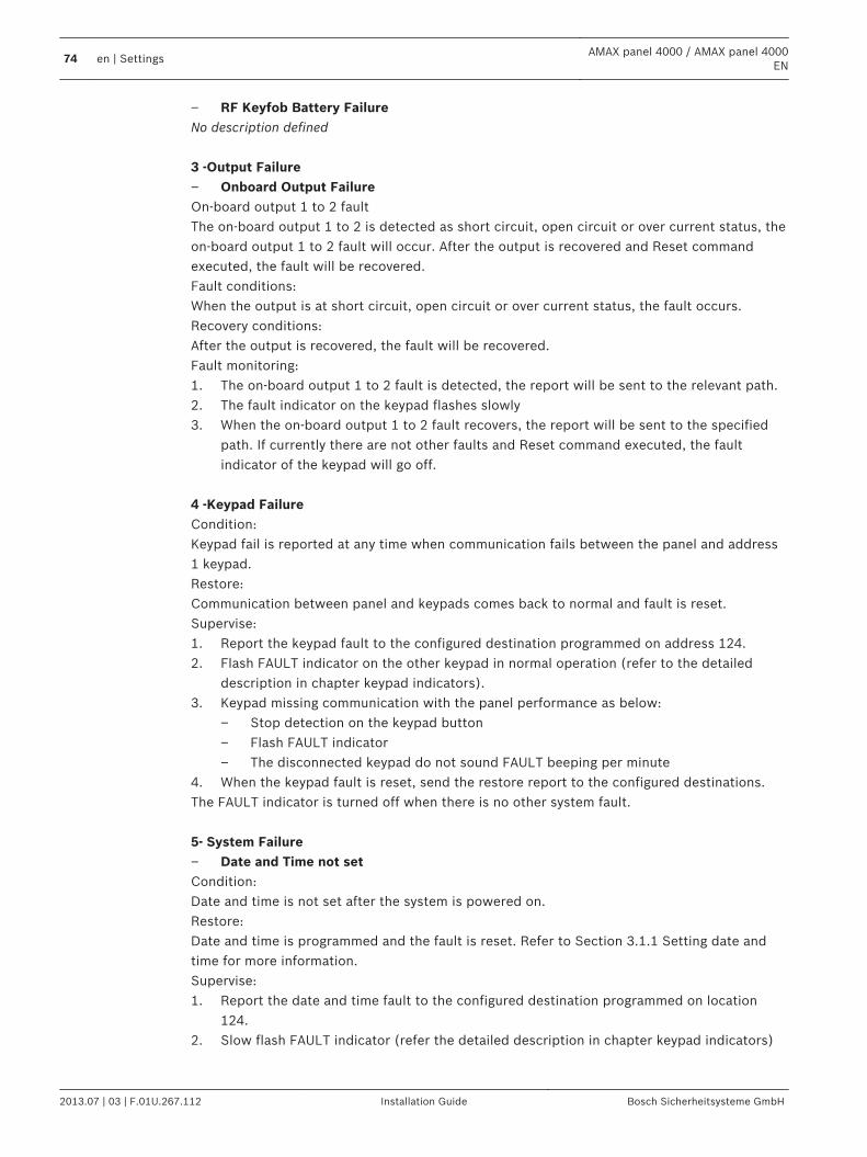
– RF Keyfob Battery FailureNo description defined 3 -Output Failure– Onboard Output FailureOn-board output 1 to 2 faultThe on-board output 1 to 2 is detected as short circuit, open circuit or over current status, theon-board output 1 to 2 fault will occur. After the output is recovered and Reset commandexecuted, the fault will be recovered.Fault conditions:When the output is at short circuit, open circuit or over current status, the fault occurs.Recovery conditions:After the output is recovered, the fault will be recovered.Fault monitoring:1. The on-board output 1 to 2 fault is detected, the report will be sent to the relevant path.2. The fault indicator on the keypad flashes slowly3. When the on-board output 1 to 2 fault recovers, the report will be sent to the specified
path. If currently there are not other faults and Reset command executed, the faultindicator of the keypad will go off.
4 -Keypad FailureCondition:Keypad fail is reported at any time when communication fails between the panel and address1 keypad.Restore:Communication between panel and keypads comes back to normal and fault is reset.Supervise:1. Report the keypad fault to the configured destination programmed on address 124.2. Flash FAULT indicator on the other keypad in normal operation (refer to the detailed
description in chapter keypad indicators).3. Keypad missing communication with the panel performance as below:
– Stop detection on the keypad button– Flash FAULT indicator– The disconnected keypad do not sound FAULT beeping per minute
4. When the keypad fault is reset, send the restore report to the configured destinations.The FAULT indicator is turned off when there is no other system fault. 5- System Failure– Date and Time not setCondition:Date and time is not set after the system is powered on.Restore:Date and time is programmed and the fault is reset. Refer to Section 3.1.1 Setting date andtime for more information.Supervise:1. Report the date and time fault to the configured destination programmed on location
124.2. Slow flash FAULT indicator (refer the detailed description in chapter keypad indicators)
74 en | SettingsAMAX panel 4000 / AMAX panel 4000
EN
2013.07 | 03 | F.01U.267.112 Installation Guide Bosch Sicherheitsysteme GmbH
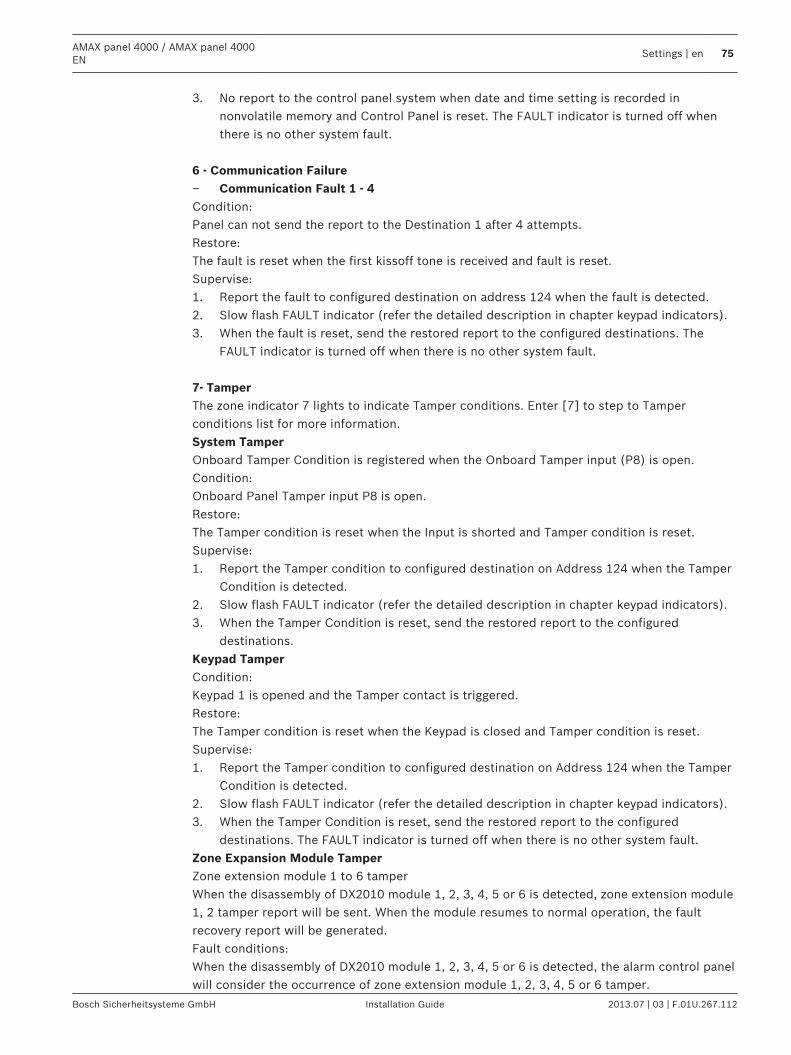
3. No report to the control panel system when date and time setting is recorded innonvolatile memory and Control Panel is reset. The FAULT indicator is turned off whenthere is no other system fault.
6 - Communication Failure– Communication Fault 1 - 4Condition:Panel can not send the report to the Destination 1 after 4 attempts.Restore:The fault is reset when the first kissoff tone is received and fault is reset.Supervise:1. Report the fault to configured destination on address 124 when the fault is detected.2. Slow flash FAULT indicator (refer the detailed description in chapter keypad indicators).3. When the fault is reset, send the restored report to the configured destinations. The
FAULT indicator is turned off when there is no other system fault. 7- TamperThe zone indicator 7 lights to indicate Tamper conditions. Enter [7] to step to Tamperconditions list for more information.System TamperOnboard Tamper Condition is registered when the Onboard Tamper input (P8) is open.Condition:Onboard Panel Tamper input P8 is open.Restore:The Tamper condition is reset when the Input is shorted and Tamper condition is reset.Supervise:1. Report the Tamper condition to configured destination on Address 124 when the Tamper
Condition is detected.2. Slow flash FAULT indicator (refer the detailed description in chapter keypad indicators).3. When the Tamper Condition is reset, send the restored report to the configured
destinations.Keypad TamperCondition:Keypad 1 is opened and the Tamper contact is triggered.Restore:The Tamper condition is reset when the Keypad is closed and Tamper condition is reset.Supervise:1. Report the Tamper condition to configured destination on Address 124 when the Tamper
Condition is detected.2. Slow flash FAULT indicator (refer the detailed description in chapter keypad indicators).3. When the Tamper Condition is reset, send the restored report to the configured
destinations. The FAULT indicator is turned off when there is no other system fault.Zone Expansion Module TamperZone extension module 1 to 6 tamperWhen the disassembly of DX2010 module 1, 2, 3, 4, 5 or 6 is detected, zone extension module1, 2 tamper report will be sent. When the module resumes to normal operation, the faultrecovery report will be generated.Fault conditions:When the disassembly of DX2010 module 1, 2, 3, 4, 5 or 6 is detected, the alarm control panelwill consider the occurrence of zone extension module 1, 2, 3, 4, 5 or 6 tamper.
AMAX panel 4000 / AMAX panel 4000EN
Settings | en 75
Bosch Sicherheitsysteme GmbH Installation Guide 2013.07 | 03 | F.01U.267.112
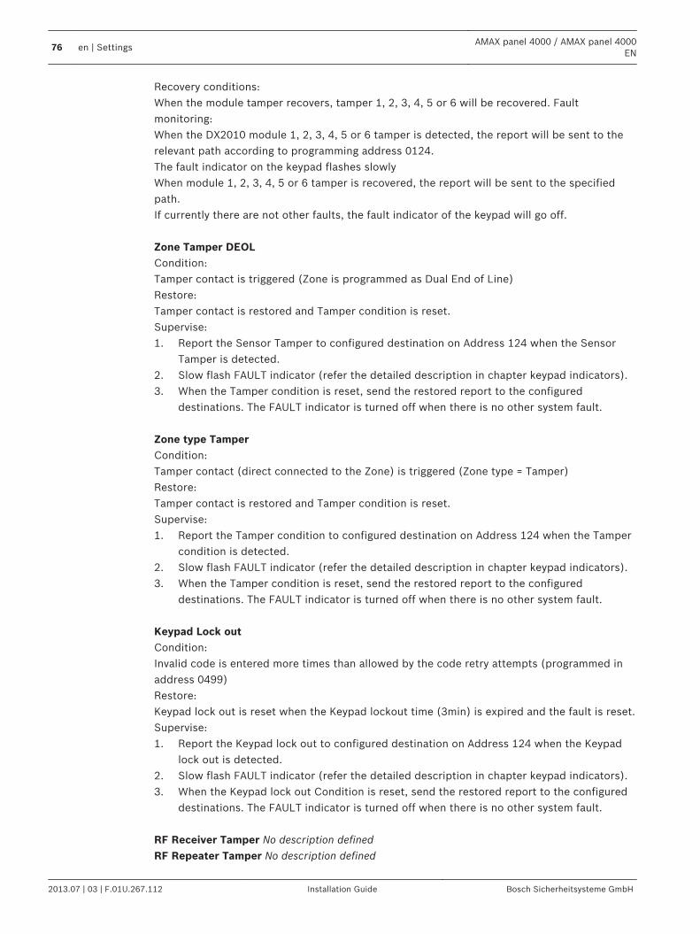
Recovery conditions:When the module tamper recovers, tamper 1, 2, 3, 4, 5 or 6 will be recovered. Faultmonitoring:When the DX2010 module 1, 2, 3, 4, 5 or 6 tamper is detected, the report will be sent to therelevant path according to programming address 0124.The fault indicator on the keypad flashes slowlyWhen module 1, 2, 3, 4, 5 or 6 tamper is recovered, the report will be sent to the specifiedpath.If currently there are not other faults, the fault indicator of the keypad will go off. Zone Tamper DEOLCondition:Tamper contact is triggered (Zone is programmed as Dual End of Line)Restore:Tamper contact is restored and Tamper condition is reset.Supervise:1. Report the Sensor Tamper to configured destination on Address 124 when the Sensor
Tamper is detected.2. Slow flash FAULT indicator (refer the detailed description in chapter keypad indicators).3. When the Tamper condition is reset, send the restored report to the configured
destinations. The FAULT indicator is turned off when there is no other system fault. Zone type TamperCondition:Tamper contact (direct connected to the Zone) is triggered (Zone type = Tamper)Restore:Tamper contact is restored and Tamper condition is reset.Supervise:1. Report the Tamper condition to configured destination on Address 124 when the Tamper
condition is detected.2. Slow flash FAULT indicator (refer the detailed description in chapter keypad indicators).3. When the Tamper condition is reset, send the restored report to the configured
destinations. The FAULT indicator is turned off when there is no other system fault. Keypad Lock outCondition:Invalid code is entered more times than allowed by the code retry attempts (programmed inaddress 0499)Restore:Keypad lock out is reset when the Keypad lockout time (3min) is expired and the fault is reset.Supervise:1. Report the Keypad lock out to configured destination on Address 124 when the Keypad
lock out is detected.2. Slow flash FAULT indicator (refer the detailed description in chapter keypad indicators).3. When the Keypad lock out Condition is reset, send the restored report to the configured
destinations. The FAULT indicator is turned off when there is no other system fault. RF Receiver Tamper No description definedRF Repeater Tamper No description defined
76 en | SettingsAMAX panel 4000 / AMAX panel 4000
EN
2013.07 | 03 | F.01U.267.112 Installation Guide Bosch Sicherheitsysteme GmbH
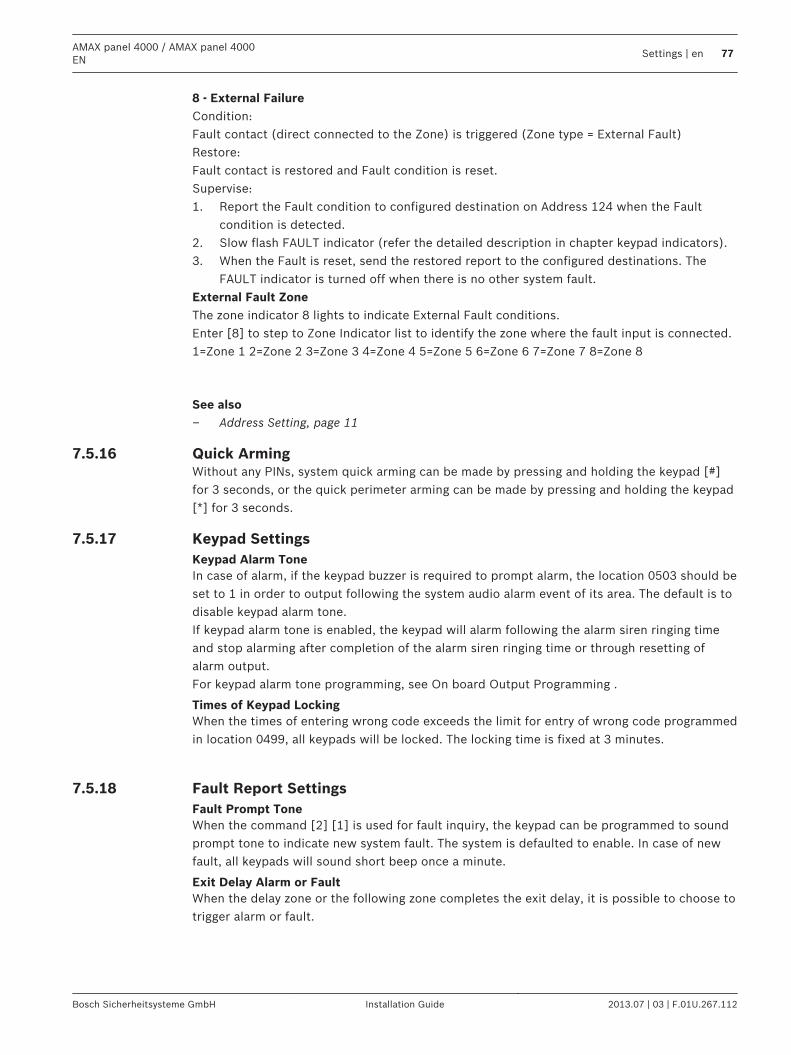
8 - External FailureCondition:Fault contact (direct connected to the Zone) is triggered (Zone type = External Fault)Restore:Fault contact is restored and Fault condition is reset.Supervise:1. Report the Fault condition to configured destination on Address 124 when the Fault
condition is detected.2. Slow flash FAULT indicator (refer the detailed description in chapter keypad indicators).3. When the Fault is reset, send the restored report to the configured destinations. The
FAULT indicator is turned off when there is no other system fault.External Fault ZoneThe zone indicator 8 lights to indicate External Fault conditions.Enter [8] to step to Zone Indicator list to identify the zone where the fault input is connected.1=Zone 1 2=Zone 2 3=Zone 3 4=Zone 4 5=Zone 5 6=Zone 6 7=Zone 7 8=Zone 8
See also– Address Setting, page 11
Quick ArmingWithout any PINs, system quick arming can be made by pressing and holding the keypad [#]for 3 seconds, or the quick perimeter arming can be made by pressing and holding the keypad[*] for 3 seconds.
Keypad SettingsKeypad Alarm ToneIn case of alarm, if the keypad buzzer is required to prompt alarm, the location 0503 should beset to 1 in order to output following the system audio alarm event of its area. The default is todisable keypad alarm tone.If keypad alarm tone is enabled, the keypad will alarm following the alarm siren ringing timeand stop alarming after completion of the alarm siren ringing time or through resetting ofalarm output.For keypad alarm tone programming, see On board Output Programming .
Times of Keypad LockingWhen the times of entering wrong code exceeds the limit for entry of wrong code programmedin location 0499, all keypads will be locked. The locking time is fixed at 3 minutes.
Fault Report SettingsFault Prompt ToneWhen the command [2] [1] is used for fault inquiry, the keypad can be programmed to soundprompt tone to indicate new system fault. The system is defaulted to enable. In case of newfault, all keypads will sound short beep once a minute.
Exit Delay Alarm or FaultWhen the delay zone or the following zone completes the exit delay, it is possible to choose totrigger alarm or fault.
7.5.16
7.5.17
7.5.18
AMAX panel 4000 / AMAX panel 4000EN
Settings | en 77
Bosch Sicherheitsysteme GmbH Installation Guide 2013.07 | 03 | F.01U.267.112
AC Fault Report SettingsIn case of AC power fault, the fault report will be delayed for 1 hour or 10 minutes, ortransmitted along with other reports. The AC power fault event will be displayed on thekeypad 1 hour or 10 minutes later.
Fault Display SettingsIn case of date/time settings fault, it is possible to choose to display the fault or transmit faultprompt tone at the same time, or do not display and stop fault prompt tone. If it is chosen notto display, even the fault prompt tone is set, the system will prompt nothing if no date andtime are set after power-up.
Version InformationThis setting can be used to display the version number of the alarm control panel software.
Restoring to Default SettingsThis setting can be used to restore all programming parameters set in the factory.
Zone Tamper Bypass when DEOL Zone is BypassedIf Parameter Zone Tamper Bypass when DEOL Zone is Bypassed is enabled, system creates atamper alarm when DEOL zone is tampered, even when this zone is bypassed. Modify address0184 in order to change parameter. This function is only accessible in address programming.Also refer to Chapter Dual IP Settings, page 107 for more details.
System Settings - RF Options RF Receiver FunctionalityEnables or disables RF receiver functionality
RF Supervision IntervalDefines RF Supervision Interval
RF Jam Detect LevelDefines RF jam detect level
RF Device Low Level Battery ResoundEnables or disables RF device low level battery resound
Chirp On Arm / DisarmEnables or disables chirp on arm / disarm
Keyfob Panic OptionDefines keyfob panic option
Area Settings
Common AreaArea 1 can be used as a common area or an independent area. Common area ancillary acts asfollows:– Only all belonged independent areas are armed, the common area can be armed.– When a relevant ancillary area is perimeter arming, the common area will be perimeter
arming too.– When a relevant ancillary area is disarmed, the common area will be armed.
7.5.19
7.6
7.7
7.7.1
78 en | SettingsAMAX panel 4000 / AMAX panel 4000
EN
2013.07 | 03 | F.01U.267.112 Installation Guide Bosch Sicherheitsysteme GmbH
– If any zones under common zones are in triggered or tamper status and the forced armingis disabled, the common area cannot be armed.
For programming of common area, see Common Area Settings.
Area DelayExit DelayAs for the programming of exit delay, the programming rang is 0 - 255 seconds. In the mode ofsystem arming, the keypad will beep during exiting and will make continuous long beep in thelast 10 seconds to notify the exit time is coming to an end.For programming of exit delay, see Exit Delay.
Entry DelayAs for the programming of entry delay, the programming rang is 0 - 255 seconds. Entry delayid the delay time of the delay zone.For programming of exit delay, see Entry Delay.For more information about delay zone, see Delay zone.
Keypad AreaMaster KeypadThe system supports up to 16 master keypads. The arming/disarming, area alarm, AC powerfault, system fault and system event of each area can be displayed on the master keypad. It isnot possible to execute arming/disarming and bypass operation on the master keypad. Whenrelevant operations are made to the area, the master keypad should be switched to thecorresponding area.
Area KeypadIt is possible to operate each area with a single or multiple independent keypads.Each area keypad can only operate the corresponding area of the programming,When the area keypad has not corresponding zones, the area keypad cannot be used toexecute zone-related operations such as arming/disarming and bypass, but can be used toexecute operations without relations to the zone, e.g. event inquiry.Each area keypad can display the status of the zone belonging to the area. However, for IUI-AMAX3-LED8 keypad, IUI-AMAX-LED8 keypad and IUI-AMAX-LCD8 keypad, each area candisplay up to 8 zones and cannot display other zones, but can report zone events. For IUI-AMAX3-LED16 keypad, each area can display up to 16 zones and cannot display other zones,but can report zone events. The keypad can display up to 64 zones.For any areas, the logic numbers of the zones are displayed on the LED/Icon LCD keypad andlogic numbers or zone names of the zones are displayed on the keypad instead of actualphysical numbers. For example: The zones 1, 2 and 3 of area 1 displayed on the keypad areactually zones 20, 31 and 37.For programming of keypad specified area, see Keypad Area Settings.
7.7.2
7.7.3
AMAX panel 4000 / AMAX panel 4000EN
Settings | en 79
Bosch Sicherheitsysteme GmbH Installation Guide 2013.07 | 03 | F.01U.267.112
ConfigurationThis chapter specifies how to configure of the AMAX panel 4000. It includes the different waysto program the AMAX panel 4000.
System Power UpAfter the system is powered up, set date and time. Otherwise, the system prompts as fault.After the system is powered up or reset, it resets to previous arming / disarming status.To reduce false alarms caused by system power-up (or by power supply restoration after bothmains supply and AUX power supply fail), the system is designed to not perform zone testwithin one minute after power-up.
System Status IndicatorThe system status is indicated by the LED status indicator on the system main board.Slow flash of red status indicator (repeating on and off with an interval of 1 second) indicatesnormal system operation.
Installer and User Code CommandsThe system supports programmable 4- to 6-digit Installer and User Code to execute thefollowing programming and operating commands.The installer commands can be used only when all areas of the system are in disarming statuswith no alarm activated and when installer access is enabled from user.
Notice!
No identical User Codes are allowed. User Codes are not permitted to be the same as
Installer codes.
8
8.1
8.2
8.3
80 en | ConfigurationAMAX panel 4000 / AMAX panel 4000
EN
2013.07 | 03 | F.01U.267.112 Installation Guide Bosch Sicherheitsysteme GmbH
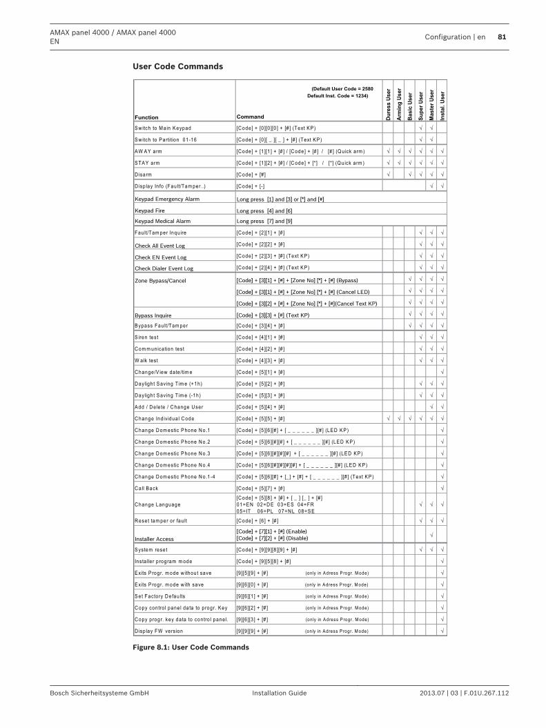
User Code Commands
Function
(Default User Code = 2580
Default Inst. Code = 1234)
Command Du
res
s U
se
r
Arm
ing
Us
er
Ba
sic
Us
er
Su
pe
r U
se
r
Ma
ste
r U
se
r
Ins
tal.
Us
er
S w itch to M a in K eypad [C ode ] + [0 ][0 ][0 ] + [# ] (Text K P ) √ √
S w itch to P artition 01 -16 [C ode ] + [0 ][ _ ][ _ ] + [# ] (Text K P ) √ √
A W A Y arm [C ode] + [1 ][1 ] + [# ] / [C ode ] + [# ] / [# ] (Q u ick a rm ) √ √ √ √ √ √
S TA Y arm [C ode] + [1 ][2 ] + [# ] / [C ode ] + [*] / [*] (Q u ick a rm ) √ √ √ √ √ √
D isarm [C ode] + [# ] √ √ √ √ √
D isp lay In fo (Fau lt/Tam per..) [C ode ] + [-] √ √
Keypad Emergency Alarm
Keypad Fire
Keypad Medical Alarm Long press [7] and [9]
Fau lt/Tam per Inqu ire [C ode ] + [2 ][1 ] + [# ] √ √ √
Check All Event Log [C ode ] + [2 ][2 ] + [# ] √ √ √
Check EN Event Log [C ode ] + [2 ][3 ] + [# ] (Text K P ) √ √ √
Check Dialer Event Log [C ode ] + [2 ][4 ] + [# ] (Text K P ) √ √ √
Zone Bypass/Cancel [Code] + [3][1] + [#] + [Zone No] [*] + [#] (Bypass) √ √ √ √
[Code] + [3][1] + [#] + [Zone No] [*] + [#] (Cancel LED) √ √ √ √
[Code] + [3][2] + [#] + [Zone No] [*] + [#](Cancel Text KP) √ √ √ √
Bypass Inquire [Code] + [3][3] + [#] (Text KP) √ √ √ √
B ypass Fau lt/Tam per [C ode ] + [3 ][4 ] + [# ] √ √ √ √
S iren tes t [C ode ] + [4 ][1 ] + [# ] √ √ √
C om m un ica tion tes t [C ode ] + [4 ][2 ] + [# ] √ √ √
W alk tes t [C ode ] + [4 ][3 ] + [# ] √ √ √
C hange/V iew da te /tim e [C ode ] + [5 ][1 ] + [# ] √
D ayligh t S aving T im e (+1h) [C ode ] + [5 ][2 ] + [# ] √ √ √
D ayligh t S aving T im e (-1h) [C ode ] + [5 ][3 ] + [# ] √ √ √
A dd / D e le te / C hange U ser [C ode ] + [5 ][4 ] + [# ] √ √
C hange Ind iv idua l C ode [C ode ] + [5 ][5 ] + [# ] √ √ √ √ √ √
C hange D om estic P hone N o.1 [C ode ] + [5 ][6 ][# ] + [ _ _ _ _ _ _ ][# ] (LE D K P ) √
C hange D om estic P hone N o.2 [C ode ] + [5 ][6 ][# ][# ] + [ _ _ _ _ _ _ ][# ] (LE D K P ) √
C hange D om estic P hone N o.3 [C ode ] + [5 ][6 ][# ][# ][# ] + [ _ _ _ _ _ _ ][# ] (LE D K P ) √
C hange D om estic P hone N o.4 [C ode ] + [5 ][6 ][# ][# ][# ][# ] + [ _ _ _ _ _ _ ][# ] (LE D K P ) √
C hange D om estic P hone N o.1 -4 [C ode ] + [5 ][6 ][# ] + [_ ] + [# ] + [ _ _ _ _ _ _ ][# ] (Text K P ) √
C a ll B ack [C ode ] + [5 ][7 ] + [# ] √
C hange Language[C ode ] + [5 ][8 ] + [# ] + [ _ ] [_ ] + [# ]01=E N 02=D E 03=E S 04=FR 05= IT 06=P L 07=N L 08=S E
√ √ √
R ese t tam per o r fau lt [C ode ] + [6 ] + [# ] √ √ √
Installer Access
[Code] + [7][1] + [#] (Enable)
[Code] + [7][2] + [#] (Disable)√
S ystem rese t [C ode ] + [9 ][9 ][8 ][9 ] + [# ] √ √ √
Ins ta lle r p rogram m ode [C ode ] + [9 ][5 ][8 ] + [# ] √
E xits P rogr. m ode w ithou t save [9 ][5 ][9 ] + [# ] (on ly in A dress P rogr. M ode) √
E xits P rogr. m ode w ith save [9 ][6 ][0 ] + [# ] (on ly in A dress P rogr. M ode) √
S et Facto ry D e fau lts [9 ][6 ][1 ] + [# ] (on ly in A dress P rogr. M ode) √
C opy con tro l pane l da ta to p rogr. K ey [9 ][6 ][2 ] + [# ] (on ly in A dress P rogr. M ode) √
C opy p rogr. key da ta to con tro l pane l. [9 ][6 ][3 ] + [# ] (on ly in A dress P rogr. M ode) √
D isp lay FW vers ion [9 ][9 ][9 ] + [# ] (on ly in A dress P rogr. M ode) √
Long press [1] and [3] or [*] and [#]
Long press [4] and [6]
Figure 8.1: User Code Commands
AMAX panel 4000 / AMAX panel 4000EN
Configuration | en 81
Bosch Sicherheitsysteme GmbH Installation Guide 2013.07 | 03 | F.01U.267.112
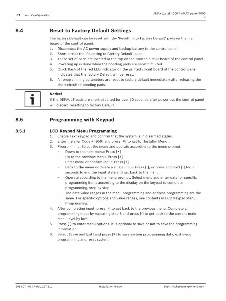
Reset to Factory Default SettingsThe factory Default can be reset with the ‘Resetting to Factory Default’ pads on the mainboard of the control panel.1. Disconnect the AC power supply and backup battery to the control panel.2. Short-circuit the ‘Resetting to Factory Default’ pads.3. These set of pads are located at the top on the printed circuit board of the control panel.4. Powering up is done when the bonding pads are short-circuited.5. Quick flash of the red LED indicator on the printed circuit board of the control panel
indicates that the factory Default will be reset.6. All programming parameters are reset to factory default immediately after releasing the
short-circuited bonding pads.
Notice!
If the DEFAULT pads are short-circuited for over 10 seconds after power-up, the control panel
will discard resetting to factory Default.
Programming with Keypad
LCD Keypad Menu Programming 1. Enable Text keypad and confirm that the system is in disarmed status.2. Enter Installer Code + [958] and press [#] to get to [Installer Menu].3. Programming: Select the menu and operate according to the menu prompt.
– Down to the next menu: Press []– Up to the previous menu: Press []– Enter menu or confirm input: Press [#]– Back to the menu or delete a single input: Press [-]; or press and hold [-] for 3
seconds to end the input state and get back to the menu.– Operate according to the menu prompt. Select menu and enter data for specific
programming items according to the display on the keypad to completeprogramming, step by step.
– The data value ranges in the menu programming and address programming are thesame. For specific options and value ranges, see contents in LCD Keypad MenuProgramming.
4. After completing input, press [-] to get back to the previous menu. Complete allprogramming input by repeating step 3 and press [-] to get back to the current mainmenu level by level.
5. Press [-] to enter menu options. It is optional to save or not to save the programminginformation.
6. Select [Save and Exit] and press [#] to save system programming data, exit menuprogramming and reset system.
8.4
8.5
8.5.1
82 en | ConfigurationAMAX panel 4000 / AMAX panel 4000
EN
2013.07 | 03 | F.01U.267.112 Installation Guide Bosch Sicherheitsysteme GmbH
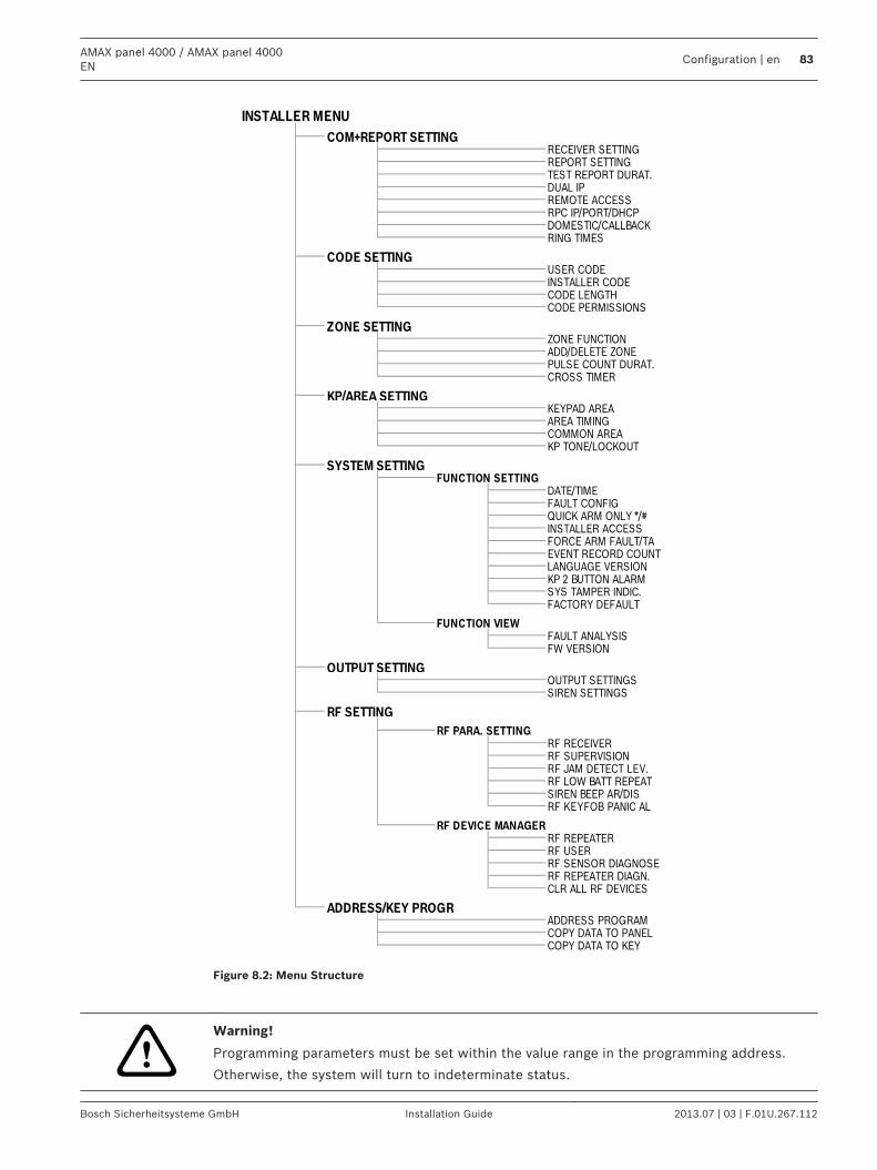
COPY DATA TO KEY
FUNCTION VIEWFAULT ANALYSIS
RF SETTING
RF RECEIVER
RF SENSOR DIAGNOSE
CLR ALL RF DEVICES
SIREN SETTINGS
ZONE FUNCTION
QUICK ARM ONLY */#INSTALLER ACCESS
EVENT RECORD COUNT
SYSTEM SETTING
ADD/DELETE ZONEPULSE COUNT DURAT.
RING TIMES
CODE SETTING
RPC IP/PORT/DHCP
INSTALLER MENU
COM+REPORT SETTINGRECEIVER SETTINGREPORT SETTING
RF LOW BATT REPEATSIREN BEEP AR/DIS
ADDRESS PROGRAMCOPY DATA TO PANEL
ADDRESS/KEY PROGR
RF DEVICE MANAGER
RF USER
RF REPEATER DIAGN.
RF REPEATER
RF JAM DETECT LEV.
RF KEYFOB PANIC AL
RF SUPERVISION
OUTPUT SETTINGS
RF PARA. SETTING
FORCE ARM FAULT/TA
FW VERSION
OUTPUT SETTING
SYS TAMPER INDIC.
DATE/TIME
FACTORY DEFAULT
LANGUAGE VERSIONKP 2 BUTTON ALARM
KP TONE/LOCKOUT
FUNCTION SETTING
FAULT CONFIG
KEYPAD AREAAREA TIMINGCOMMON AREA
CROSS TIMER
ZONE SETTING
TEST REPORT DURAT.DUAL IPREMOTE ACCESS
DOMESTIC/CALLBACK
INSTALLER CODE
CODE PERMISSIONS
KP/AREA SETTING
CODE LENGTH
USER CODE
Figure 8.2: Menu Structure
!Warning!
Programming parameters must be set within the value range in the programming address.
Otherwise, the system will turn to indeterminate status.
AMAX panel 4000 / AMAX panel 4000EN
Configuration | en 83
Bosch Sicherheitsysteme GmbH Installation Guide 2013.07 | 03 | F.01U.267.112
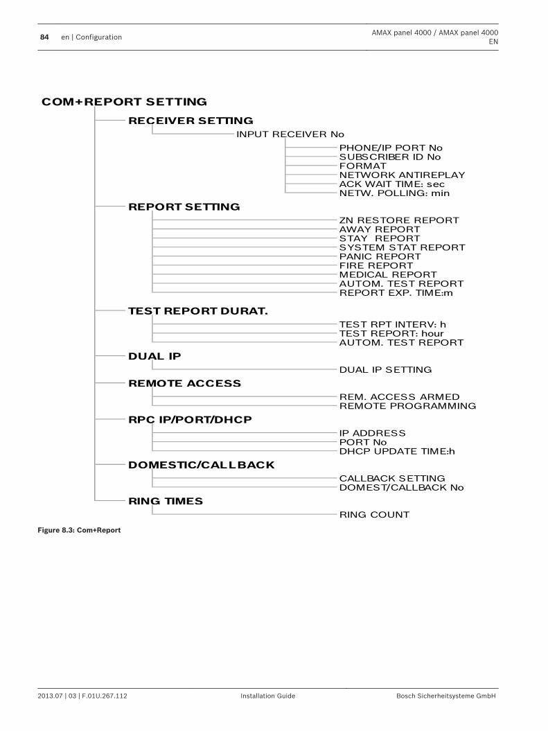
ZN RESTORE REPORTAWAY REPORTSTAY REPORTSYSTEM STAT REPORTPANIC REPORTFIRE REPORTMEDICAL REPORTAUTOM. TEST REPORTREPORT EXP. TIME:m
TEST RPT INTERV: hTEST REPORT: hourAUTOM. TEST REPORT
TEST REPORT DURAT.
DUAL IP SETTING
REM. ACCESS ARMEDREMOTE PROGRAMMING
DUAL IP
REMOTE ACCESS
RPC IP/PORT/DHCP
IP ADDRESSPORT NoDHCP UPDATE TIME:h
CALLBACK SETTINGDOMEST/CALLBACK No
DOMESTIC/CALLBACK
RING COUNT
RING TIMES
COM+REPORT SETTING
RECEIVER SETTING
INPUT RECEIVER No
PHONE/IP PORT NoSUBSCRIBER ID No
REPORT SETTING
FORMATNETWORK ANTIREPLAYACK WAIT TIME: secNETW. POLLING: min
Figure 8.3: Com+Report
84 en | ConfigurationAMAX panel 4000 / AMAX panel 4000
EN
2013.07 | 03 | F.01U.267.112 Installation Guide Bosch Sicherheitsysteme GmbH
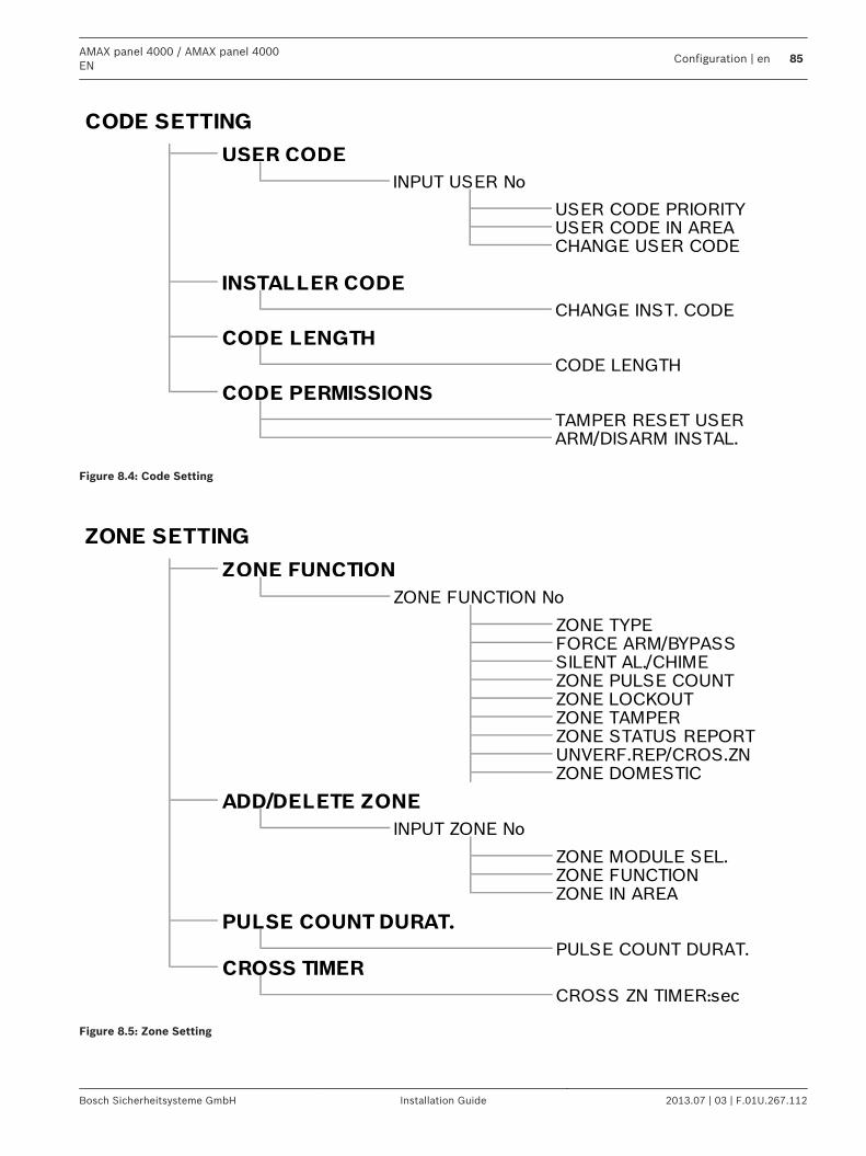
CODE PERMISSIONS
TAMPER RESET USERARM/DISARM INSTAL.
CHANGE INST. CODE
CODE LENGTH
CODE LENGTH
USER CODE IN AREACHANGE USER CODE
INSTALLER CODE
USER CODE
INPUT USER No
USER CODE PRIORITY
CODE SETTING
Figure 8.4: Code Setting
PULSE COUNT DURAT.CROSS TIMER
CROSS ZN TIMER:sec
ZONE FUNCTIONZONE IN AREA
PULSE COUNT DURAT.
ADD/DELETE ZONE
INPUT ZONE No
ZONE MODULE SEL.
ZONE STATUS REPORTUNVERF.REP/CROS.ZNZONE DOMESTIC
ZONE PULSE COUNTZONE LOCKOUTZONE TAMPER
ZONE TYPEFORCE ARM/BYPASSSILENT AL./CHIME
ZONE SETTING
ZONE FUNCTION
ZONE FUNCTION No
Figure 8.5: Zone Setting
AMAX panel 4000 / AMAX panel 4000EN
Configuration | en 85
Bosch Sicherheitsysteme GmbH Installation Guide 2013.07 | 03 | F.01U.267.112
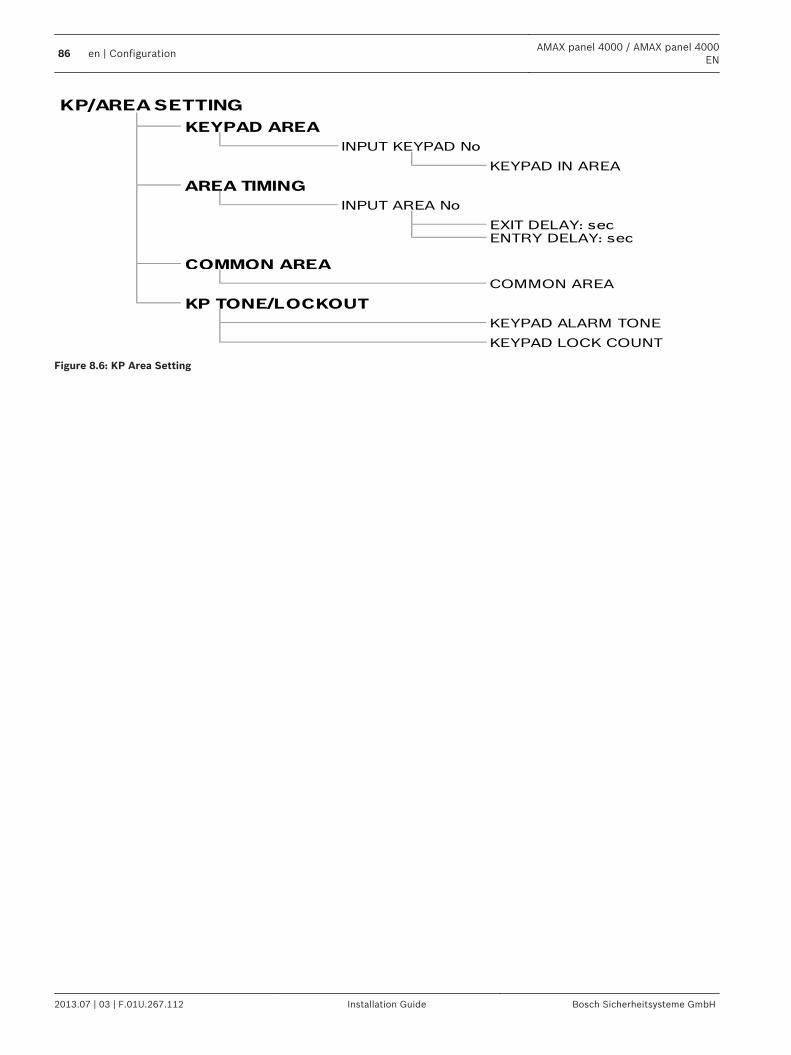
KEYPAD IN AREA
AREA TIMING
INPUT AREA No
EXIT DELAY: sec
KP/AREA SETTING
KEYPAD AREA
INPUT KEYPAD No
ENTRY DELAY: sec
COMMON AREA
COMMON AREA
KP TONE/LOCKOUT
KEYPAD ALARM TONE
KEYPAD LOCK COUNT
Figure 8.6: KP Area Setting
86 en | ConfigurationAMAX panel 4000 / AMAX panel 4000
EN
2013.07 | 03 | F.01U.267.112 Installation Guide Bosch Sicherheitsysteme GmbH
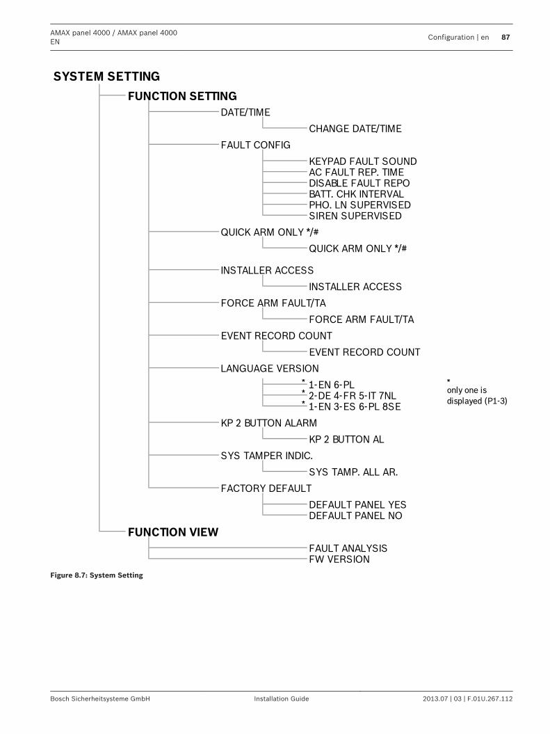
* *
*
*
FAULT ANALYSISFW VERSION
DEFAULT PANEL YESDEFAULT PANEL NO
FUNCTION VIEW
SYS TAMPER INDIC.
SYS TAMP. ALL AR.
FACTORY DEFAULT
1-EN 3-ES 6-PL 8SE
KP 2 BUTTON ALARM
KP 2 BUTTON AL
LANGUAGE VERSION
1-EN 6-PLonly one is
2-DE 4-FR 5-IT 7NLdisplayed (P1-3)
FORCE ARM FAULT/TA
EVENT RECORD COUNT
EVENT RECORD COUNT
INSTALLER ACCESS
INSTALLER ACCESS
FORCE ARM FAULT/TA
SIREN SUPERVISED
QUICK ARM ONLY */#
QUICK ARM ONLY */#
DISABLE FAULT REPOBATT. CHK INTERVALPHO. LN SUPERVISED
FAULT CONFIG
KEYPAD FAULT SOUNDAC FAULT REP. TIME
FUNCTION SETTING
DATE/TIME
CHANGE DATE/TIME
SYSTEM SETTING
Figure 8.7: System Setting
AMAX panel 4000 / AMAX panel 4000EN
Configuration | en 87
Bosch Sicherheitsysteme GmbH Installation Guide 2013.07 | 03 | F.01U.267.112
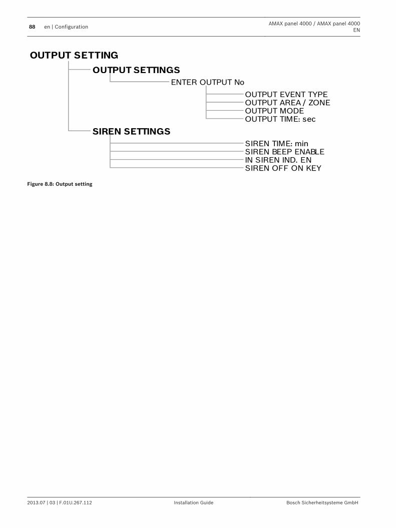
IN SIREN IND. ENSIREN OFF ON KEY
SIREN SETTINGS
SIREN TIME: minSIREN BEEP ENABLE
OUTPUT AREA / ZONEOUTPUT MODEOUTPUT TIME: sec
OUTPUT SETTINGS
ENTER OUTPUT No
OUTPUT EVENT TYPE
OUTPUT SETTING
Figure 8.8: Output setting
88 en | ConfigurationAMAX panel 4000 / AMAX panel 4000
EN
2013.07 | 03 | F.01U.267.112 Installation Guide Bosch Sicherheitsysteme GmbH
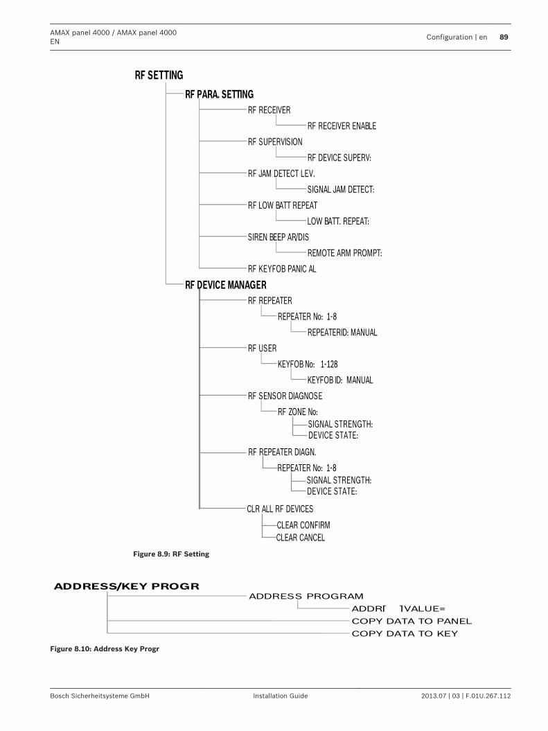
KEYFOB ID: MANUAL
RF SENSOR DIAGNOSE
RF ZONE No:
REPEATERID: MANUAL
RF USER
KEYFOB No: 1-128
RF DEVICE MANAGER
RF REPEATER
REPEATER No: 1-8
SIREN BEEP AR/DIS
REMOTE ARM PROMPT:
RF KEYFOB PANIC AL
SIGNAL JAM DETECT:
RF LOW BATT REPEAT
LOW BATT. REPEAT:
RF SUPERVISION
RF DEVICE SUPERV:
RF JAM DETECT LEV.
RF PARA. SETTING
RF RECEIVER
RF RECEIVER ENABLE
RF SETTING
CLEAR CONFIRM
CLEAR CANCEL
CLR ALL RF DEVICES
RF REPEATER DIAGN.
REPEATER No: 1-8
SIGNAL STRENGTH:DEVICE STATE:
SIGNAL STRENGTH:DEVICE STATE:
Figure 8.9: RF Setting
COPY DATA TO KEY
ADDRESS/KEY PROGR
ADDRESS PROGRAM
ADDR[ ]VALUE=
COPY DATA TO PANEL
Figure 8.10: Address Key Progr
AMAX panel 4000 / AMAX panel 4000EN
Configuration | en 89
Bosch Sicherheitsysteme GmbH Installation Guide 2013.07 | 03 | F.01U.267.112
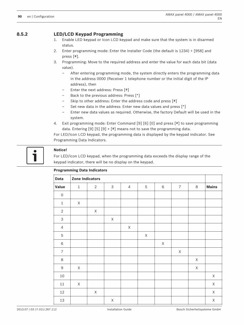
LED/LCD Keypad Programming1. Enable LED keypad or Icon LCD keypad and make sure that the system is in disarmed
status.2. Enter programming mode: Enter the Installer Code (the default is 1234) + [958] and
press [#].3. Programming: Move to the required address and enter the value for each data bit (data
value).– After entering programming mode, the system directly enters the programming data
in the address 0000 (Receiver 1 telephone number or the initial digit of the IPaddress), then
– Enter the next address: Press [#]– Back to the previous address: Press [*]– Skip to other address: Enter the address code and press [#]– Set new data in the address: Enter new data values and press [*]– Enter new data values as required. Otherwise, the factory Default will be used in the
system.4. Exit programming mode: Enter Command [9] [6] [0] and press [#] to save programming
data. Entering [9] [5] [9] + [#] means not to save the programming data.For LED/Icon LCD keypad, the programming data is displayed by the keypad indicator. SeeProgramming Data Indicators.
Notice!
For LED/Icon LCD keypad, when the programming data exceeds the display range of the
keypad indicator, there will be no display on the keypad.
Programming Data Indicators
Data Zone Indicators
Value 1 2 3 4 5 6 7 8 Mains
0
1 X
2 X
3 X
4 X
5 X
6 X
7 X
8 X
9 X X
10 X
11 X X
12 X X
13 X X
8.5.2
90 en | ConfigurationAMAX panel 4000 / AMAX panel 4000
EN
2013.07 | 03 | F.01U.267.112 Installation Guide Bosch Sicherheitsysteme GmbH
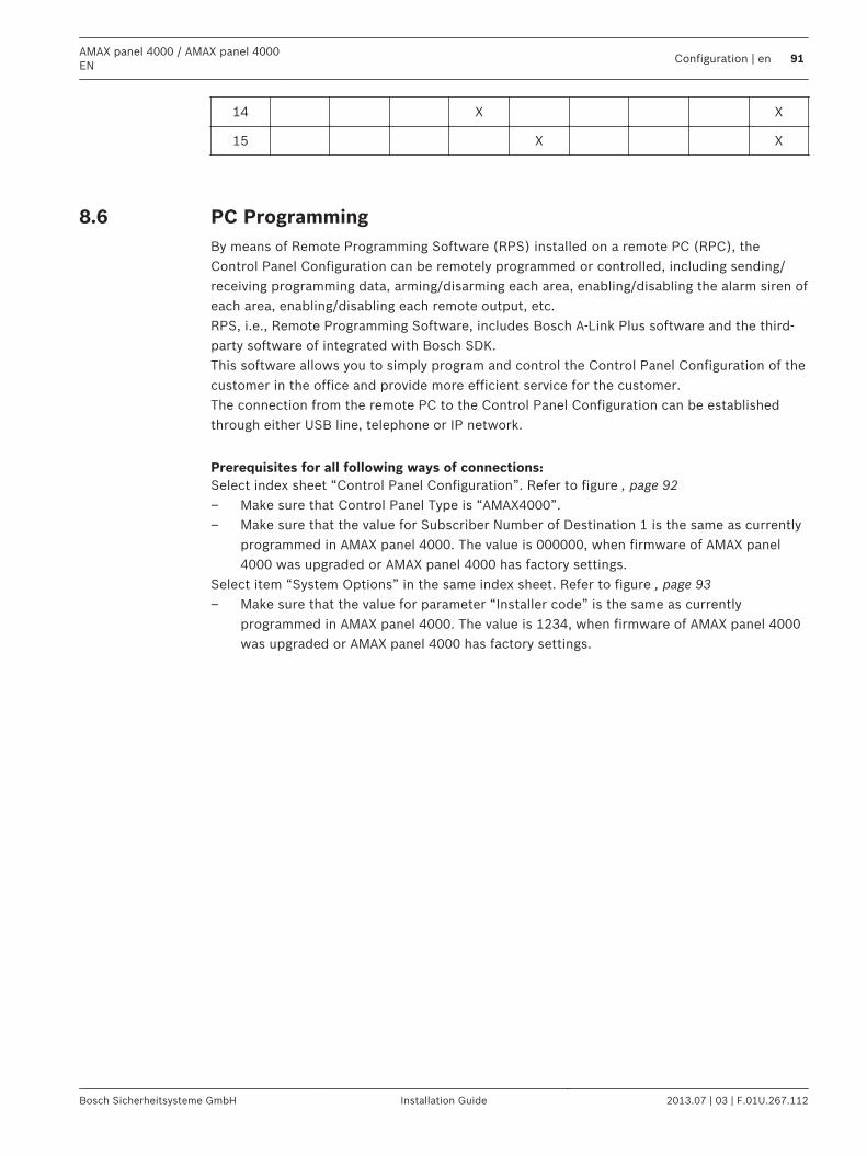
14 X X
15 X X
PC ProgrammingBy means of Remote Programming Software (RPS) installed on a remote PC (RPC), theControl Panel Configuration can be remotely programmed or controlled, including sending/receiving programming data, arming/disarming each area, enabling/disabling the alarm siren ofeach area, enabling/disabling each remote output, etc.RPS, i.e., Remote Programming Software, includes Bosch A-Link Plus software and the third-party software of integrated with Bosch SDK.This software allows you to simply program and control the Control Panel Configuration of thecustomer in the office and provide more efficient service for the customer.The connection from the remote PC to the Control Panel Configuration can be establishedthrough either USB line, telephone or IP network.
Prerequisites for all following ways of connections:Select index sheet “Control Panel Configuration”. Refer to figure , page 92– Make sure that Control Panel Type is “AMAX4000”.– Make sure that the value for Subscriber Number of Destination 1 is the same as currently
programmed in AMAX panel 4000. The value is 000000, when firmware of AMAX panel4000 was upgraded or AMAX panel 4000 has factory settings.
Select item “System Options” in the same index sheet. Refer to figure , page 93– Make sure that the value for parameter “Installer code” is the same as currently
programmed in AMAX panel 4000. The value is 1234, when firmware of AMAX panel 4000was upgraded or AMAX panel 4000 has factory settings.
8.6
AMAX panel 4000 / AMAX panel 4000EN
Configuration | en 91
Bosch Sicherheitsysteme GmbH Installation Guide 2013.07 | 03 | F.01U.267.112
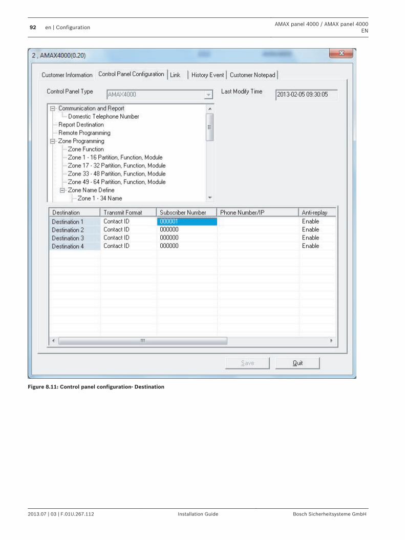
Figure 8.11: Control panel configuration- Destination
92 en | ConfigurationAMAX panel 4000 / AMAX panel 4000
EN
2013.07 | 03 | F.01U.267.112 Installation Guide Bosch Sicherheitsysteme GmbH
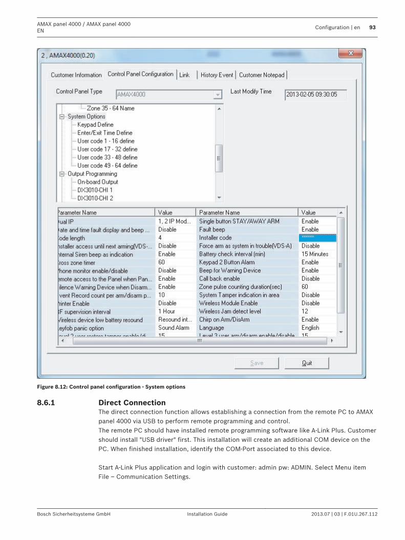
Figure 8.12: Control panel configuration - System options
Direct ConnectionThe direct connection function allows establishing a connection from the remote PC to AMAXpanel 4000 via USB to perform remote programming and control.The remote PC should have installed remote programming software like A-Link Plus. Customershould install "USB driver" first. This installation will create an additional COM device on thePC. When finished installation, identify the COM-Port associated to this device. Start A-Link Plus application and login with customer: admin pw: ADMIN. Select Menu itemFile – Communication Settings.
8.6.1
AMAX panel 4000 / AMAX panel 4000EN
Configuration | en 93
Bosch Sicherheitsysteme GmbH Installation Guide 2013.07 | 03 | F.01U.267.112
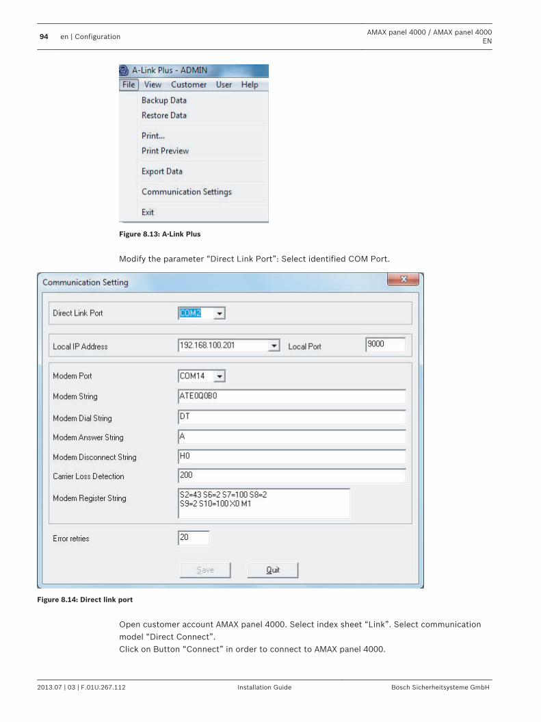
Figure 8.13: A-Link Plus
Modify the parameter “Direct Link Port”: Select identified COM Port.
Figure 8.14: Direct link port
Open customer account AMAX panel 4000. Select index sheet “Link”. Select communicationmodel “Direct Connect”.Click on Button “Connect” in order to connect to AMAX panel 4000.
94 en | ConfigurationAMAX panel 4000 / AMAX panel 4000
EN
2013.07 | 03 | F.01U.267.112 Installation Guide Bosch Sicherheitsysteme GmbH
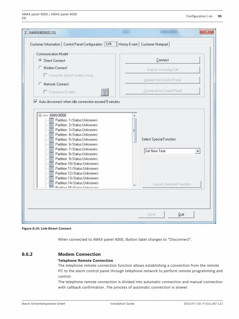
Figure 8.15: Link-Direct Connect
When connected to AMAX panel 4000, Button label changes to “Disconnect”.
Modem ConnectionTelephone Remote ConnectionThe telephone remote connection function allows establishing a connection from the remotePC to the alarm control panel through telephone network to perform remote programming andcontrol.The telephone remote connection is divided into automatic connection and manual connectionwith callback confirmation. The process of automatic connection is slower.
8.6.2
AMAX panel 4000 / AMAX panel 4000EN
Configuration | en 95
Bosch Sicherheitsysteme GmbH Installation Guide 2013.07 | 03 | F.01U.267.112
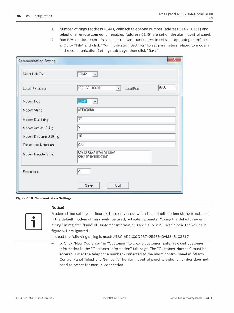
1. Number of rings (address 0144), callback telephone number (address 0146 - 0161) andtelephone remote connection enabled (address 0145) are set on the alarm control panel.
2. Run RPS on the remote PC and set relevant parameters in relevant operating interfaces.– a. Go to “File” and click “Communication Settings” to set parameters related to modem
in the communication Settings tab page, then click “Save”.
Figure 8.16: Communication Settings
Notice!
Modem string settings in figure x.1 are only used, when the default modem string is not used.
If the default modem string should be used, activate parameter “Using the default modem
string” in register “Link” of Customer Information (see figure x.2). In this case the values in
figure x.1 are ignored.
Instead the following string is used: AT&CI&D2X0&Q0S7=255S9=0+MS=B103B17
– b. Click “New Customer” in “Customer” to create customer. Enter relevant customerinformation in the “Customer Information” tab page. The “Customer Number” must beentered. Enter the telephone number connected to the alarm control panel in “AlarmControl Panel Telephone Number”. The alarm control panel telephone number does notneed to be set for manual connection.
96 en | ConfigurationAMAX panel 4000 / AMAX panel 4000
EN
2013.07 | 03 | F.01U.267.112 Installation Guide Bosch Sicherheitsysteme GmbH
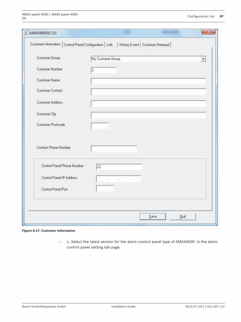
Figure 8.17: Customer Information
– c. Select the latest version for the alarm control panel type of AMAX4000- in the alarm
control panel setting tab page.
AMAX panel 4000 / AMAX panel 4000EN
Configuration | en 97
Bosch Sicherheitsysteme GmbH Installation Guide 2013.07 | 03 | F.01U.267.112
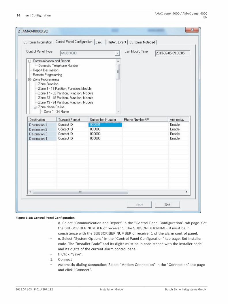
Figure 8.18: Control Panel Configuration
– d. Select “Communication and Report” in the “Control Panel Configuration” tab page. Setthe SUBSCRIBER NUMBER of receiver 1. The SUBSCRIBER NUMBER must be inconsistence with the SUBSCRIBER NUMBER of receiver 1 of the alarm control panel.
– e. Select “System Options” in the “Control Panel Configuration” tab page. Set installercode. The “Installer Code” and its digits must be in consistence with the installer codeand its digits of the current alarm control panel.
– f. Click “Save”.1. Connect– Automatic dialing connection: Select “Modem Connection” in the “Connection” tab page
and click “Connect”.
98 en | ConfigurationAMAX panel 4000 / AMAX panel 4000
EN
2013.07 | 03 | F.01U.267.112 Installation Guide Bosch Sicherheitsysteme GmbH
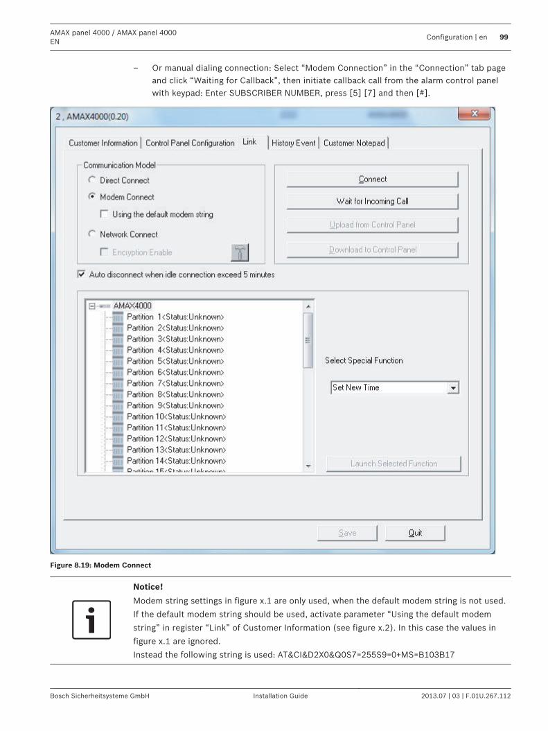
– Or manual dialing connection: Select “Modem Connection” in the “Connection” tab pageand click “Waiting for Callback”, then initiate callback call from the alarm control panelwith keypad: Enter SUBSCRIBER NUMBER, press [5] [7] and then [#].
Figure 8.19: Modem Connect
Notice!
Modem string settings in figure x.1 are only used, when the default modem string is not used.
If the default modem string should be used, activate parameter “Using the default modem
string” in register “Link” of Customer Information (see figure x.2). In this case the values in
figure x.1 are ignored.
Instead the following string is used: AT&CI&D2X0&Q0S7=255S9=0+MS=B103B17
AMAX panel 4000 / AMAX panel 4000EN
Configuration | en 99
Bosch Sicherheitsysteme GmbH Installation Guide 2013.07 | 03 | F.01U.267.112
After successfully connected, RPS can execute multiple operations, including reading/writingcontrol panel parameters, remote arming/disarming, viewing log, etc. After the telephone issuccessfully connected, RPS will disconnect it with the alarm control panel after 5 minutes ofidling.
IP ConnectionIP Remote ConnectionThe IP remote connection function allows to establish a connection from the remote PC to thealarm control panel through LAN or WAN to perform remote programming and control. Theremote monitoring center should be installed remote programming software like A-Link Plusand perform related IP address programming in order to apply this function in LAN (supportDHCP) and WAN.The IP remote connection is divided into automatic connection and manual connection withcallback confirmation.For more information about IP programming, see IP Address, page 441. Set receiver 1 SUBSCRIBER NUMBER (addresses 0017 - 0022), network remote settings
programming option (addresses 0162 - 0179), i.e., enter IP address and port number ofRPS, DHCP update time on the alarm control panel.
2. Run RPS on the remote PC and set relevant parameters in relevant operating interfaces– a. Go to “File” and click “Communication Settings” to select “local IP address” in the
“Communication Settings” tab page. If there are multiple IP addressed in the pull-downmenu, be sure to select the latest local IP address and enter the local port, i.e., the RPCport number of programming option 0174 – 0178, then click “Save”.
8.6.3
100 en | ConfigurationAMAX panel 4000 / AMAX panel 4000
EN
2013.07 | 03 | F.01U.267.112 Installation Guide Bosch Sicherheitsysteme GmbH
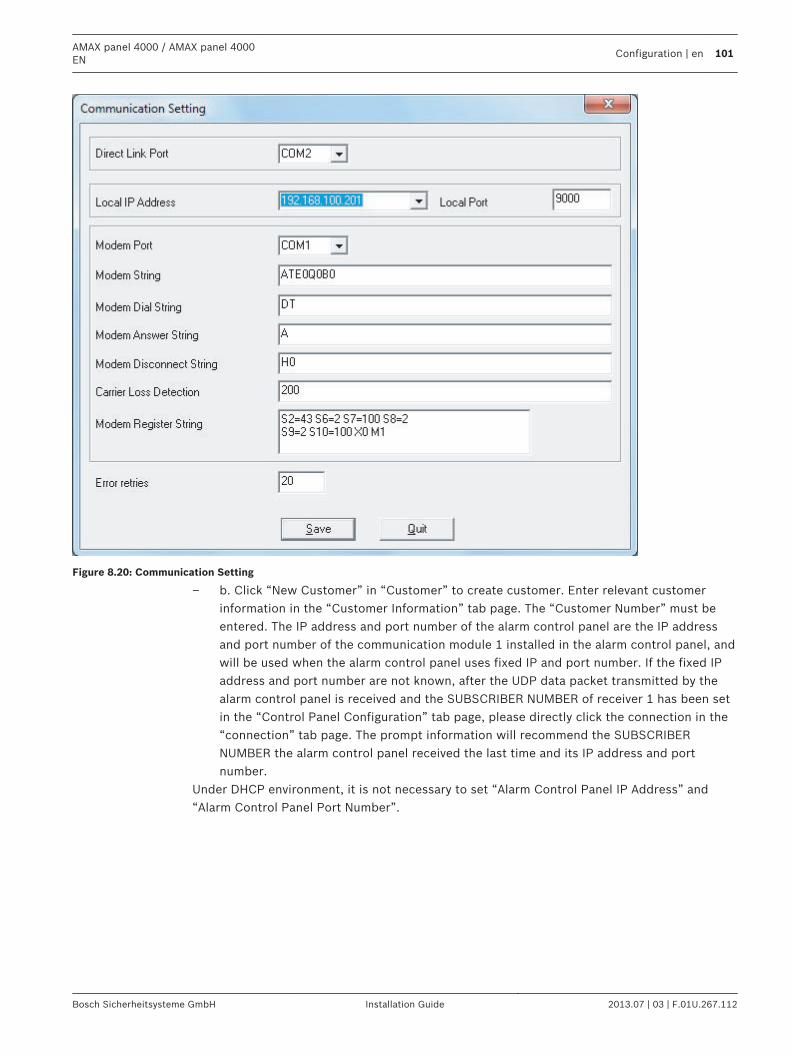
Figure 8.20: Communication Setting
– b. Click “New Customer” in “Customer” to create customer. Enter relevant customerinformation in the “Customer Information” tab page. The “Customer Number” must beentered. The IP address and port number of the alarm control panel are the IP addressand port number of the communication module 1 installed in the alarm control panel, andwill be used when the alarm control panel uses fixed IP and port number. If the fixed IPaddress and port number are not known, after the UDP data packet transmitted by thealarm control panel is received and the SUBSCRIBER NUMBER of receiver 1 has been setin the “Control Panel Configuration” tab page, please directly click the connection in the“connection” tab page. The prompt information will recommend the SUBSCRIBERNUMBER the alarm control panel received the last time and its IP address and portnumber.
Under DHCP environment, it is not necessary to set “Alarm Control Panel IP Address” and“Alarm Control Panel Port Number”.
AMAX panel 4000 / AMAX panel 4000EN
Configuration | en 101
Bosch Sicherheitsysteme GmbH Installation Guide 2013.07 | 03 | F.01U.267.112
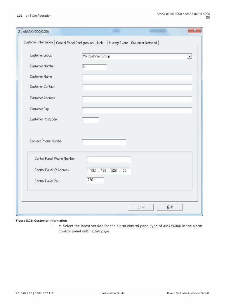
Figure 8.21: Customer Information
– c. Select the latest version for the alarm control panel type of AMAX4000 in the alarmcontrol panel setting tab page.
102 en | ConfigurationAMAX panel 4000 / AMAX panel 4000
EN
2013.07 | 03 | F.01U.267.112 Installation Guide Bosch Sicherheitsysteme GmbH
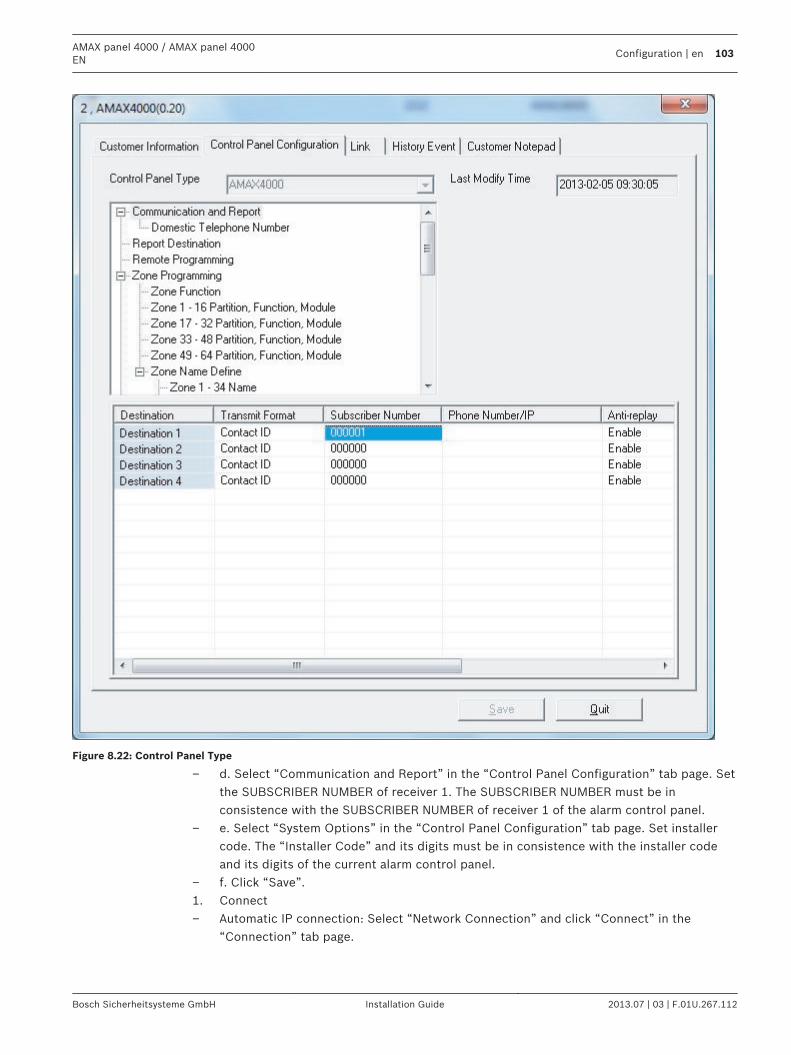
Figure 8.22: Control Panel Type
– d. Select “Communication and Report” in the “Control Panel Configuration” tab page. Setthe SUBSCRIBER NUMBER of receiver 1. The SUBSCRIBER NUMBER must be inconsistence with the SUBSCRIBER NUMBER of receiver 1 of the alarm control panel.
– e. Select “System Options” in the “Control Panel Configuration” tab page. Set installercode. The “Installer Code” and its digits must be in consistence with the installer codeand its digits of the current alarm control panel.
– f. Click “Save”.1. Connect– Automatic IP connection: Select “Network Connection” and click “Connect” in the
“Connection” tab page.
AMAX panel 4000 / AMAX panel 4000EN
Configuration | en 103
Bosch Sicherheitsysteme GmbH Installation Guide 2013.07 | 03 | F.01U.267.112
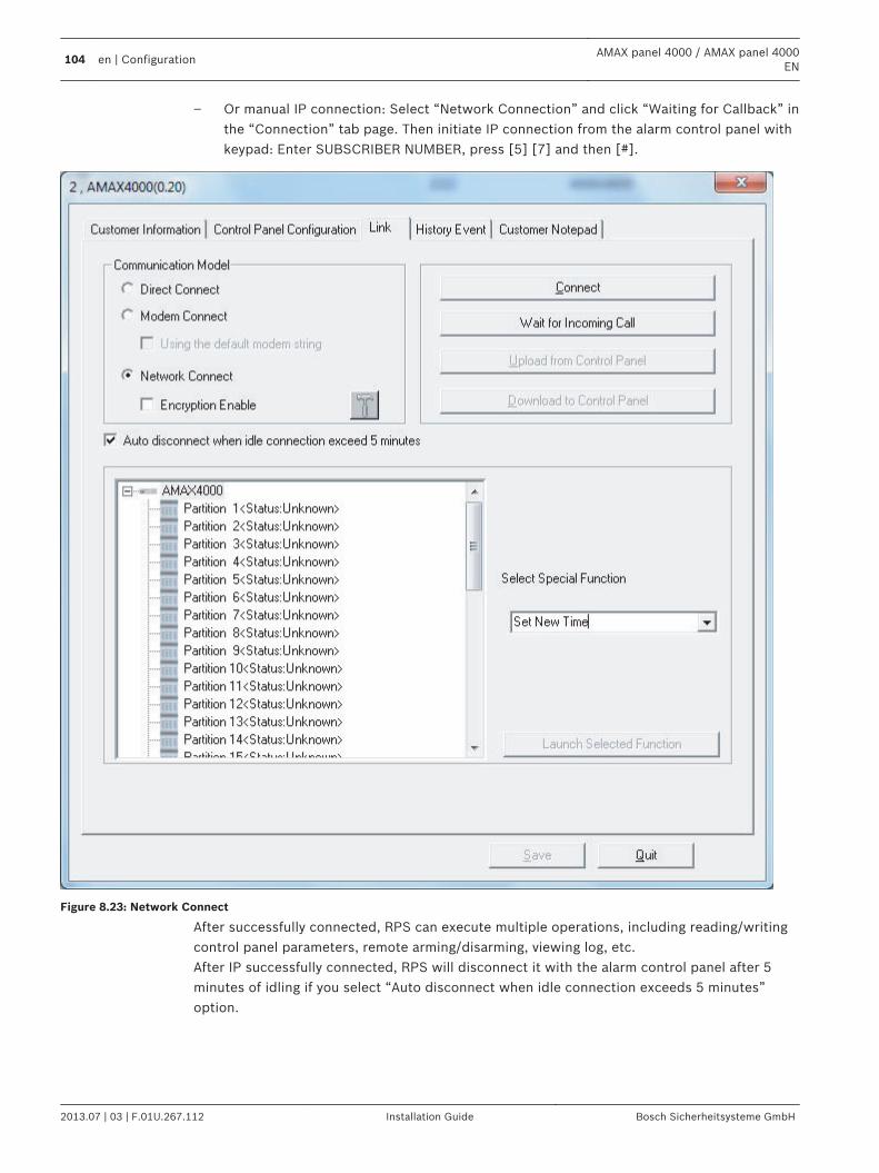
– Or manual IP connection: Select “Network Connection” and click “Waiting for Callback” inthe “Connection” tab page. Then initiate IP connection from the alarm control panel withkeypad: Enter SUBSCRIBER NUMBER, press [5] [7] and then [#].
Figure 8.23: Network Connect
After successfully connected, RPS can execute multiple operations, including reading/writingcontrol panel parameters, remote arming/disarming, viewing log, etc.After IP successfully connected, RPS will disconnect it with the alarm control panel after 5minutes of idling if you select “Auto disconnect when idle connection exceeds 5 minutes”option.
104 en | ConfigurationAMAX panel 4000 / AMAX panel 4000
EN
2013.07 | 03 | F.01U.267.112 Installation Guide Bosch Sicherheitsysteme GmbH
Programming with the ICP-EZPK Programming Key The ICP-EZPK Programming Key allows you to save or copy programming information fromyour control panel. After saving information in the programming key, you can easily programother AMAX panel 4000 / AMAX panel 4000 EN with the same programming data. You can alsouse the programming key to back up existing information.If you have a new programming key, enter installer’s programming mode, program the systemas required, and connect the programming key to the control panel.To connect the programming key:Locate the socket labelled PROGRAMMING KEY at the top of the printed circuit board (PCB).Observe the triangular markings on the PCB and align them with the markings on theprogramming key.
For example: to copy data from the control panel to the programming key:1. Enter the installer code (the default is 1234) + (958) and press [#] to enter into installer’s
programming mode.2. Enter [9 6 2 #]. Refer to Section 6.23 Command 962 – Copy the control panel memory to
the programming key, page 46.3. Enter [9 6 0 #] to exit from installer’s programming mode.4. The system resets and returns to the disarmed state. And the programming key becomes
your standard data pattern for future control panel programming.
!
Caution!
If you do not enter installer’s programming mode first, which connects the blank ICP-EZPK
Programming Key (blue) to the control panel, no data can be uploaded /downloaded.
An unknown error may be caused if the installer’s programming mode is not exited before
removing the programming key.
Programming KeyWith the programming key, the programming parameters of the current alarm control panel toother systems with the same applications.
Copying Parameters of the Alarm Control Panel to KeyCopy the programming data in the memory of the alarm control panel into the programmingkey with the keypad.1. Connect the programming key to the plug marked as "PROGRAMMING KEY" on the top of
the printed circuit board (PCB) of the alarm control panel. Please note that the directionof the programming key should be consistent with the direction marked on the PCB.
2. Select text keypad installation menu [ADDRESS/KEY PROGR – COPY DATA TO KEY] andPress [#]. After successfully copying the programming data of the alarm control panel tothe programming key, the confirmation tone will be sounded. Wrong prompt tone anddisplay of [Failure of Control Panel Parameters to Key] indicate damage of programmingkey data. The data need to be copied into the programming key again.
3. Unplug the programming key from the alarm control panel.4. LED/Icon LCD keypad can also be used to copy alarm control panel parameters to key
parameters. See Command 962.
Copying Key Parameters to the Alarm Control PanelCopy the programming data of the programming key into the alarm center.
8.7
AMAX panel 4000 / AMAX panel 4000EN
Configuration | en 105
Bosch Sicherheitsysteme GmbH Installation Guide 2013.07 | 03 | F.01U.267.112
1. Connect the programming key to the plug marked as "PROGRAMMING KEY" on the top ofthe printed circuit board (PCB) of the alarm control panel. Please note that the directionof the programming key should be consistent with the direction marked on the PCB.
2. Select text keypad installation menu [ADDRESS/KEY PROGR – COPY DATA TO PANEL]and Press [#]. After successfully copying the programming data in programming key tothe alarm control panel, the confirmation tone will be sounded. Wrong prompt tone anddisplay of [Failure of Key Parameters to Control Panel] indicate damage of programmingkey data. The data need to be copied into the alarm control panel again.
3. Unplug the programming key from the alarm control panel.LED/Icon LCD keypad can also be used to copy key parameters to the alarm control panel. Formore information refer to Command 963 .
Firmware Upgrade with the ICP-EZRU2 Upgrade KeyUse Firmware Upgrade Key (green) to upgrade Firmware of alarm control panel.Procedure:– Power OFF alarm control panel. Also remove battery. Unplug USB cable, if plugged.– Locate the socket labeled PROGRAMMING KEY at the top of the printed circuit board
(PCB). Observe the triangular markings on the PCB and align them with the markings onthe upgrade key.
– Power ON alarm control panel. Observe LED of upgrade key lights steady during upgradeis sent to alarm control panel. This takes about one minute. When upgrade is terminated,LED is blinking.
– Remove upgrade key
8.8
106 en | ConfigurationAMAX panel 4000 / AMAX panel 4000
EN
2013.07 | 03 | F.01U.267.112 Installation Guide Bosch Sicherheitsysteme GmbH

ProgrammingThe control panel programming options are stored in a non-volatile flash memory. Thismemory has all relevant configuration and user-specific data even after a total power loss.Because the data retention time is quite long without power, reprogramming is not requiredafter powering up the control panel.Programming with keypad is possible only when all of zones in the system are in disarmedstatus and no alarm is activated. Installer Code is required for programming.
Notice!
It is not recommended to use other keypads or methods simultaneously to program the
system while programming with the current keypad.
Communication and Reports Setting
Report Options Address Default
Telephone Number / IP Address and Port for Receiver 1 0000 - 0016 15
Subscriber ID Number 0017 - 0022 000000
Transmission Format for Receiver (0 = Not used, 1 =Contact ID, 2= SIA, 3 = Conettix IP)
0023 1
Anti-replay for Receiver (0 = Disabled, 1 = Enabled) 0024 1 EN=1
Acknowledge Wait Time for Receiver (05 - 99 seconds ) 0025 - 0026 05
Network Polling Time for Receiver (001 - 999 minutes ) 0027 - 0029 001
Telephone Number / IP Address and Port for Receiver 2 0030 - 0046 15
Subscriber ID Number 0047 - 0052 000000
Transmission Format for Receiver (0 = Not used, 1 =Contact ID, 2= SIA, 3 = Conettix IP)
0053 1
Anti-replay for Receiver (0 = Disabled, 1 = Enabled) 0054 1 EN=1
Acknowledge Wait Time for Receiver (05 - 99 seconds ) 0055 - 0056 05
Network Polling Time for Receive (001 - 999 minutes) 0057 - 0059 001
Telephone Number / IP Address and Port for Receiver 3 0060 - 0076 15
Subscriber ID Number 0077 - 0082 000000
Transmission Format for Receiver (0 = Not used, 1 =Contact ID, 2= SIA, 3 = Conettix IP)
0083 1
Anti-replay for Receiver (0 = Disabled, 1 = Enabled) 0084 1 EN=1
Acknowledge Wait Time for Receiver (05 - 99 seconds) 0085 - 086 05
Network Polling Time for Receiver (001 - 999 minutes) 0087 - 089 001
Telephone Number / IP Address and Port for Receiver 4 0090 - 0106 15
Subscriber ID Number 0107 - 0112 000000
9
9.1
AMAX panel 4000 / AMAX panel 4000EN
Programming | en 107
Bosch Sicherheitsysteme GmbH Installation Guide 2013.07 | 03 | F.01U.267.112
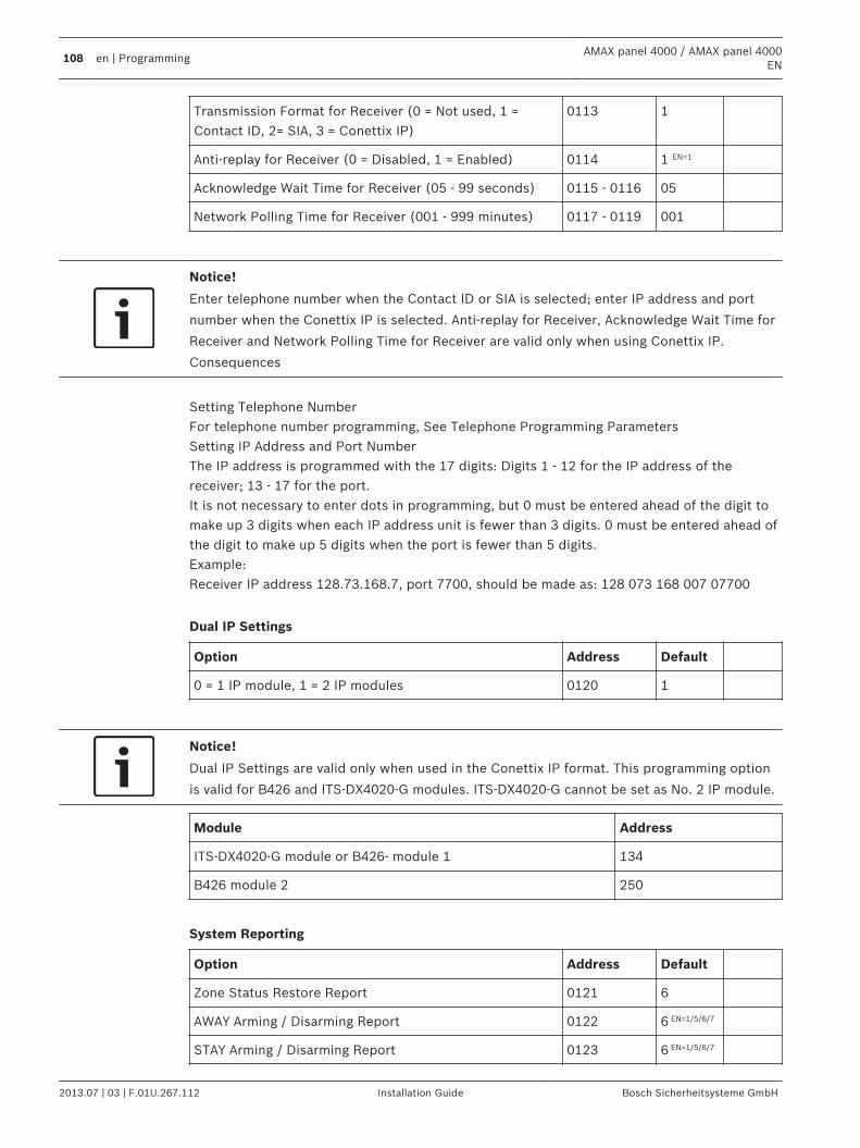
Transmission Format for Receiver (0 = Not used, 1 =Contact ID, 2= SIA, 3 = Conettix IP)
0113 1
Anti-replay for Receiver (0 = Disabled, 1 = Enabled) 0114 1 EN=1
Acknowledge Wait Time for Receiver (05 - 99 seconds) 0115 - 0116 05
Network Polling Time for Receiver (001 - 999 minutes) 0117 - 0119 001
Notice!
Enter telephone number when the Contact ID or SIA is selected; enter IP address and port
number when the Conettix IP is selected. Anti-replay for Receiver, Acknowledge Wait Time for
Receiver and Network Polling Time for Receiver are valid only when using Conettix IP.
Consequences
Setting Telephone NumberFor telephone number programming, See Telephone Programming ParametersSetting IP Address and Port NumberThe IP address is programmed with the 17 digits: Digits 1 - 12 for the IP address of thereceiver; 13 - 17 for the port.It is not necessary to enter dots in programming, but 0 must be entered ahead of the digit tomake up 3 digits when each IP address unit is fewer than 3 digits. 0 must be entered ahead ofthe digit to make up 5 digits when the port is fewer than 5 digits.Example:Receiver IP address 128.73.168.7, port 7700, should be made as: 128 073 168 007 07700
Dual IP Settings
Option Address Default
0 = 1 IP module, 1 = 2 IP modules 0120 1
Notice!
Dual IP Settings are valid only when used in the Conettix IP format. This programming option
is valid for B426 and ITS-DX4020-G modules. ITS-DX4020-G cannot be set as No. 2 IP module.
Module Address
ITS-DX4020-G module or B426- module 1 134
B426 module 2 250
System Reporting
Option Address Default
Zone Status Restore Report 0121 6
AWAY Arming / Disarming Report 0122 6 EN=1/5/6/7
STAY Arming / Disarming Report 0123 6 EN=1/5/6/7
108 en | ProgrammingAMAX panel 4000 / AMAX panel 4000
EN
2013.07 | 03 | F.01U.267.112 Installation Guide Bosch Sicherheitsysteme GmbH
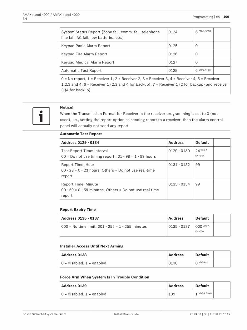
System Status Report (Zone fail, comm. fail, telephoneline fail, AC fail, low batterie...etc.)
0124 6 EN=1/5/6/7
Keypad Panic Alarm Report 0125 0
Keypad Fire Alarm Report 0126 0
Keypad Medical Alarm Report 0127 0
Automatic Test Report 0128 6 EN=1/5/6/7
0 = No report, 1 = Receiver 1, 2 = Receiver 2, 3 = Receiver 3, 4 = Receiver 4, 5 = Receiver1,2,3 and 4, 6 = Receiver 1 (2,3 and 4 for backup), 7 = Receiver 1 (2 for backup) and receiver3 (4 for backup)
Notice!
When the Transmission Format for Receiver in the receiver programming is set to 0 (not
used), i.e., setting the report option as sending report to a receiver, then the alarm control
panel will actually not send any report.
Automatic Test Report
Address 0129 - 0134 Address Default
Test Report Time: Interval00 = Do not use timing report , 01 - 99 = 1 - 99 hours
0129 - 0130 24 VDS-A
EN=1-24
Report Time: Hour00 - 23 = 0 - 23 hours, Others = Do not use real-timereport
0131 - 0132 99
Report Time: Minute00 - 59 = 0 - 59 minutes, Others = Do not use real-timereport
0133 - 0134 99
Report Expiry Time
Address 0135 - 0137 Address Default
000 = No time limit, 001 - 255 = 1 - 255 minutes 0135 - 0137 000 VDS-A
EN=000
Installer Access Until Next Arming
Address 0138 Address Default
0 = disabled, 1 = enabled 0138 0 VDS-A=1
Force Arm When System Is In Trouble Condition
Address 0139 Address Default
0 = disabled, 1 = enabled 139 1 VDS-A EN=0
AMAX panel 4000 / AMAX panel 4000EN
Programming | en 109
Bosch Sicherheitsysteme GmbH Installation Guide 2013.07 | 03 | F.01U.267.112
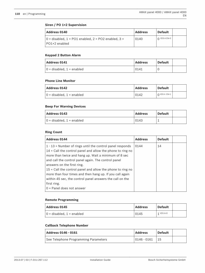
Siren / PO 1+2 Supervision
Address 0140 Address Default
0 = disabled, 1 = PO1 enabled, 2 = PO2 enabled, 3 =PO1+2 enabled
0140 0 VDS-A EN=3
Keypad 2 Button Alarm
Address 0141 Address Default
0 = disabled, 1 = enabled 0141 0
Phone Line Monitor
Address 0142 Address Default
0 = disabled, 1 = enabled 0142 0 VDS-A EN=1
Beep For Warning Devices
Address 0143 Address Default
0 = disabled, 1 = enabled 0143 1
Ring Count
Address 0144 Address Default
1 - 13 = Number of rings until the control panel responds14 = Call the control panel and allow the phone to ring nomore than twice and hang up. Wait a minimum of 8 secand call the control panel again. The control panelanswers on the first ring.15 = Call the control panel and allow the phone to ring nomore than four times and then hang up. If you call againwithin 45 sec, the control panel answers the call on thefirst ring.0 = Panel does not answer
0144 14
Remote Programming
Address 0145 Address Default
0 = disabled, 1 = enabled 0145 1 VDS-A=0
Callback Telephone Number
Address 0146 - 0161 Address Default
See Telephone Programming Parameters 0146 - 0161 15
110 en | ProgrammingAMAX panel 4000 / AMAX panel 4000
EN
2013.07 | 03 | F.01U.267.112 Installation Guide Bosch Sicherheitsysteme GmbH
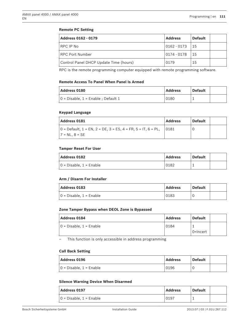
Remote PC Setting
Address 0162 - 0179 Address Default
RPC IP No 0162 - 0173 15
RPC Port Number 0174 - 0178 15
Control Panel DHCP Update Time (hours) 0179 15
RPC is the remote programming computer equipped with remote programming software.
Remote Access To Panel When Panel Is Armed
Address 0180 Address Default
0 = Disable, 1 = Enable ; Default 1 0180 1
Keypad Language
Address 0181 Address Default
0 = Default, 1 = EN, 2 = DE, 3 = ES, 4 = FR, 5 = IT, 6 = PL,7 = NL, 8 = SE
0181 0
Tamper Reset For User
Address 0182 Address Default
0 = Disable, 1 = Enable 0182 1
Arm / Disarm For Installer
Address 0183 Address Default
0 = Disable, 1 = Enable 0183 0
Zone Tamper Bypass when DEOL Zone is Bypassed
Address 0184 Address Default
0 = Disable, 1 = Enable 0184 10=Incert
– This function is only accessible in address programming
Call Back Setting
Address 0196 Address Default
0 = Disable, 1 = Enable 0196 0
Silence Warning Device When Disarmed
Address 0197 Address Default
0 = Disable, 1 = Enable 0197 1
AMAX panel 4000 / AMAX panel 4000EN
Programming | en 111
Bosch Sicherheitsysteme GmbH Installation Guide 2013.07 | 03 | F.01U.267.112
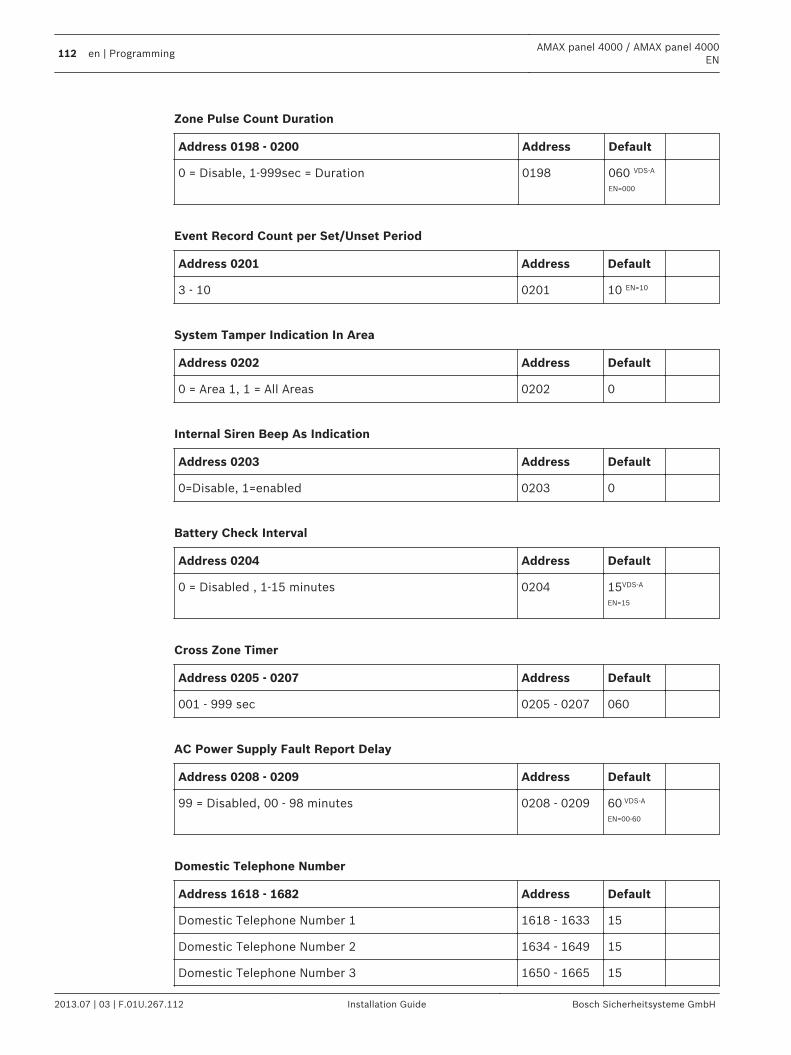
Zone Pulse Count Duration
Address 0198 - 0200 Address Default
0 = Disable, 1-999sec = Duration 0198 060 VDS-A
EN=000
Event Record Count per Set/Unset Period
Address 0201 Address Default
3 - 10 0201 10 EN=10
System Tamper Indication In Area
Address 0202 Address Default
0 = Area 1, 1 = All Areas 0202 0
Internal Siren Beep As Indication
Address 0203 Address Default
0=Disable, 1=enabled 0203 0
Battery Check Interval
Address 0204 Address Default
0 = Disabled , 1-15 minutes 0204 15VDS-A
EN=15
Cross Zone Timer
Address 0205 - 0207 Address Default
001 - 999 sec 0205 - 0207 060
AC Power Supply Fault Report Delay
Address 0208 - 0209 Address Default
99 = Disabled, 00 - 98 minutes 0208 - 0209 60 VDS-A
EN=00-60
Domestic Telephone Number
Address 1618 - 1682 Address Default
Domestic Telephone Number 1 1618 - 1633 15
Domestic Telephone Number 2 1634 - 1649 15
Domestic Telephone Number 3 1650 - 1665 15
112 en | ProgrammingAMAX panel 4000 / AMAX panel 4000
EN
2013.07 | 03 | F.01U.267.112 Installation Guide Bosch Sicherheitsysteme GmbH
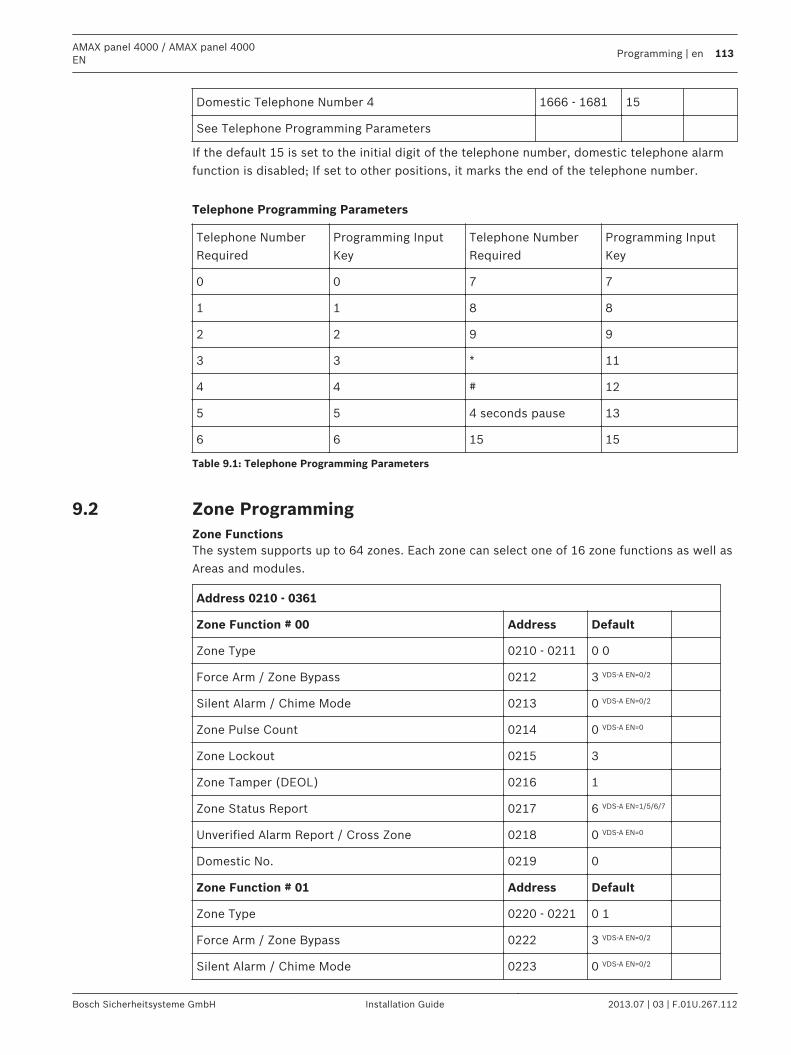
Domestic Telephone Number 4 1666 - 1681 15
See Telephone Programming Parameters
If the default 15 is set to the initial digit of the telephone number, domestic telephone alarmfunction is disabled; If set to other positions, it marks the end of the telephone number.
Telephone Programming Parameters
Telephone NumberRequired
Programming InputKey
Telephone NumberRequired
Programming InputKey
0 0 7 7
1 1 8 8
2 2 9 9
3 3 * 11
4 4 # 12
5 5 4 seconds pause 13
6 6 15 15
Table 9.1: Telephone Programming Parameters
Zone ProgrammingZone FunctionsThe system supports up to 64 zones. Each zone can select one of 16 zone functions as well asAreas and modules.
Address 0210 - 0361
Zone Function # 00 Address Default
Zone Type 0210 - 0211 0 0
Force Arm / Zone Bypass 0212 3 VDS-A EN=0/2
Silent Alarm / Chime Mode 0213 0 VDS-A EN=0/2
Zone Pulse Count 0214 0 VDS-A EN=0
Zone Lockout 0215 3
Zone Tamper (DEOL) 0216 1
Zone Status Report 0217 6 VDS-A EN=1/5/6/7
Unverified Alarm Report / Cross Zone 0218 0 VDS-A EN=0
Domestic No. 0219 0
Zone Function # 01 Address Default
Zone Type 0220 - 0221 0 1
Force Arm / Zone Bypass 0222 3 VDS-A EN=0/2
Silent Alarm / Chime Mode 0223 0 VDS-A EN=0/2
9.2
AMAX panel 4000 / AMAX panel 4000EN
Programming | en 113
Bosch Sicherheitsysteme GmbH Installation Guide 2013.07 | 03 | F.01U.267.112
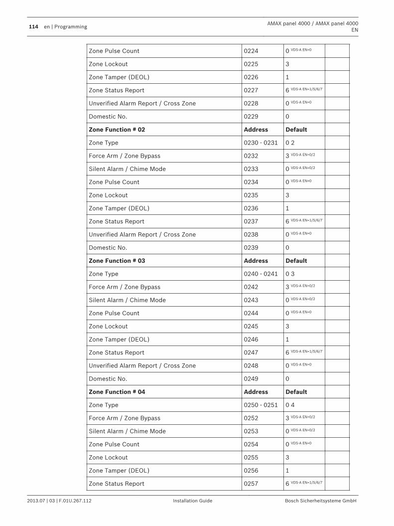
Zone Pulse Count 0224 0 VDS-A EN=0
Zone Lockout 0225 3
Zone Tamper (DEOL) 0226 1
Zone Status Report 0227 6 VDS-A EN=1/5/6/7
Unverified Alarm Report / Cross Zone 0228 0 VDS-A EN=0
Domestic No. 0229 0
Zone Function # 02 Address Default
Zone Type 0230 - 0231 0 2
Force Arm / Zone Bypass 0232 3 VDS-A EN=0/2
Silent Alarm / Chime Mode 0233 0 VDS-A EN=0/2
Zone Pulse Count 0234 0 VDS-A EN=0
Zone Lockout 0235 3
Zone Tamper (DEOL) 0236 1
Zone Status Report 0237 6 VDS-A EN=1/5/6/7
Unverified Alarm Report / Cross Zone 0238 0 VDS-A EN=0
Domestic No. 0239 0
Zone Function # 03 Address Default
Zone Type 0240 - 0241 0 3
Force Arm / Zone Bypass 0242 3 VDS-A EN=0/2
Silent Alarm / Chime Mode 0243 0 VDS-A EN=0/2
Zone Pulse Count 0244 0 VDS-A EN=0
Zone Lockout 0245 3
Zone Tamper (DEOL) 0246 1
Zone Status Report 0247 6 VDS-A EN=1/5/6/7
Unverified Alarm Report / Cross Zone 0248 0 VDS-A EN=0
Domestic No. 0249 0
Zone Function # 04 Address Default
Zone Type 0250 - 0251 0 4
Force Arm / Zone Bypass 0252 3 VDS-A EN=0/2
Silent Alarm / Chime Mode 0253 0 VDS-A EN=0/2
Zone Pulse Count 0254 0 VDS-A EN=0
Zone Lockout 0255 3
Zone Tamper (DEOL) 0256 1
Zone Status Report 0257 6 VDS-A EN=1/5/6/7
114 en | ProgrammingAMAX panel 4000 / AMAX panel 4000
EN
2013.07 | 03 | F.01U.267.112 Installation Guide Bosch Sicherheitsysteme GmbH
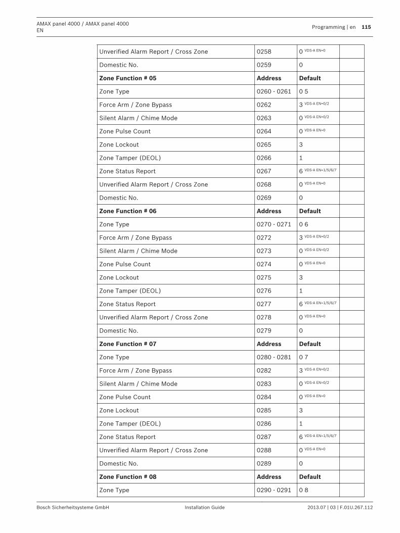
Unverified Alarm Report / Cross Zone 0258 0 VDS-A EN=0
Domestic No. 0259 0
Zone Function # 05 Address Default
Zone Type 0260 - 0261 0 5
Force Arm / Zone Bypass 0262 3 VDS-A EN=0/2
Silent Alarm / Chime Mode 0263 0 VDS-A EN=0/2
Zone Pulse Count 0264 0 VDS-A EN=0
Zone Lockout 0265 3
Zone Tamper (DEOL) 0266 1
Zone Status Report 0267 6 VDS-A EN=1/5/6/7
Unverified Alarm Report / Cross Zone 0268 0 VDS-A EN=0
Domestic No. 0269 0
Zone Function # 06 Address Default
Zone Type 0270 - 0271 0 6
Force Arm / Zone Bypass 0272 3 VDS-A EN=0/2
Silent Alarm / Chime Mode 0273 0 VDS-A EN=0/2
Zone Pulse Count 0274 0 VDS-A EN=0
Zone Lockout 0275 3
Zone Tamper (DEOL) 0276 1
Zone Status Report 0277 6 VDS-A EN=1/5/6/7
Unverified Alarm Report / Cross Zone 0278 0 VDS-A EN=0
Domestic No. 0279 0
Zone Function # 07 Address Default
Zone Type 0280 - 0281 0 7
Force Arm / Zone Bypass 0282 3 VDS-A EN=0/2
Silent Alarm / Chime Mode 0283 0 VDS-A EN=0/2
Zone Pulse Count 0284 0 VDS-A EN=0
Zone Lockout 0285 3
Zone Tamper (DEOL) 0286 1
Zone Status Report 0287 6 VDS-A EN=1/5/6/7
Unverified Alarm Report / Cross Zone 0288 0 VDS-A EN=0
Domestic No. 0289 0
Zone Function # 08 Address Default
Zone Type 0290 - 0291 0 8
AMAX panel 4000 / AMAX panel 4000EN
Programming | en 115
Bosch Sicherheitsysteme GmbH Installation Guide 2013.07 | 03 | F.01U.267.112
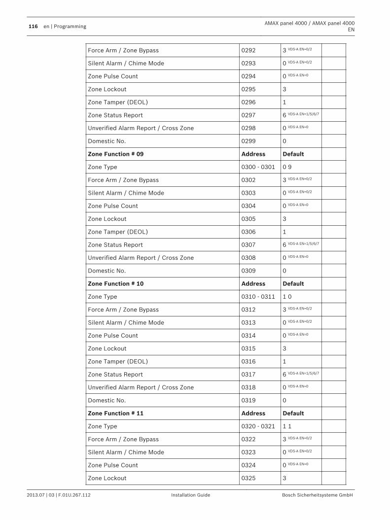
Force Arm / Zone Bypass 0292 3 VDS-A EN=0/2
Silent Alarm / Chime Mode 0293 0 VDS-A EN=0/2
Zone Pulse Count 0294 0 VDS-A EN=0
Zone Lockout 0295 3
Zone Tamper (DEOL) 0296 1
Zone Status Report 0297 6 VDS-A EN=1/5/6/7
Unverified Alarm Report / Cross Zone 0298 0 VDS-A EN=0
Domestic No. 0299 0
Zone Function # 09 Address Default
Zone Type 0300 - 0301 0 9
Force Arm / Zone Bypass 0302 3 VDS-A EN=0/2
Silent Alarm / Chime Mode 0303 0 VDS-A EN=0/2
Zone Pulse Count 0304 0 VDS-A EN=0
Zone Lockout 0305 3
Zone Tamper (DEOL) 0306 1
Zone Status Report 0307 6 VDS-A EN=1/5/6/7
Unverified Alarm Report / Cross Zone 0308 0 VDS-A EN=0
Domestic No. 0309 0
Zone Function # 10 Address Default
Zone Type 0310 - 0311 1 0
Force Arm / Zone Bypass 0312 3 VDS-A EN=0/2
Silent Alarm / Chime Mode 0313 0 VDS-A EN=0/2
Zone Pulse Count 0314 0 VDS-A EN=0
Zone Lockout 0315 3
Zone Tamper (DEOL) 0316 1
Zone Status Report 0317 6 VDS-A EN=1/5/6/7
Unverified Alarm Report / Cross Zone 0318 0 VDS-A EN=0
Domestic No. 0319 0
Zone Function # 11 Address Default
Zone Type 0320 - 0321 1 1
Force Arm / Zone Bypass 0322 3 VDS-A EN=0/2
Silent Alarm / Chime Mode 0323 0 VDS-A EN=0/2
Zone Pulse Count 0324 0 VDS-A EN=0
Zone Lockout 0325 3
116 en | ProgrammingAMAX panel 4000 / AMAX panel 4000
EN
2013.07 | 03 | F.01U.267.112 Installation Guide Bosch Sicherheitsysteme GmbH
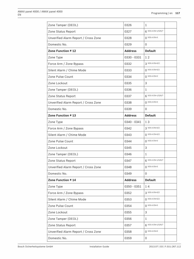
Zone Tamper (DEOL) 0326 1
Zone Status Report 0327 6 VDS-A EN=1/5/6/7
Unverified Alarm Report / Cross Zone 0328 0 VDS-A EN=0
Domestic No. 0329 0
Zone Function # 12 Address Default
Zone Type 0330 - 0331 1 2
Force Arm / Zone Bypass 0332 3 VDS-A EN=0/2
Silent Alarm / Chime Mode 0333 0 VDS-A EN=0/2
Zone Pulse Count 0334 0 VDS-A EN=0
Zone Lockout 0335 3
Zone Tamper (DEOL) 0336 1
Zone Status Report 0337 6 VDS-A EN=1/5/6/7
Unverified Alarm Report / Cross Zone 0338 0 VDS-A EN=0
Domestic No. 0339 0
Zone Function # 13 Address Default
Zone Type 0340 - 0341 1 3
Force Arm / Zone Bypass 0342 3 VDS-A EN=0/2
Silent Alarm / Chime Mode 0343 0 VDS-A EN=0/2
Zone Pulse Count 0344 0 VDS-A EN=0
Zone Lockout 0345 3
Zone Tamper (DEOL) 0346 1
Zone Status Report 0347 6 VDS-A EN=1/5/6/7
Unverified Alarm Report / Cross Zone 0348 0 VDS-A EN=0
Domestic No. 0349 0
Zone Function # 14 Address Default
Zone Type 0350 - 0351 1 4
Force Arm / Zone Bypass 0352 3 VDS-A EN=0/2
Silent Alarm / Chime Mode 0353 0 VDS-A EN=0/2
Zone Pulse Count 0354 0 VDS-A EN=0
Zone Lockout 0355 3
Zone Tamper (DEOL) 0356 1
Zone Status Report 0357 6 VDS-A EN=1/5/6/7
Unverified Alarm Report / Cross Zone 0358 0 VDS-A EN=0
Domestic No. 0359 0
AMAX panel 4000 / AMAX panel 4000EN
Programming | en 117
Bosch Sicherheitsysteme GmbH Installation Guide 2013.07 | 03 | F.01U.267.112
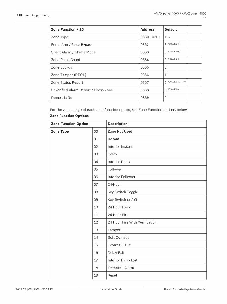
Zone Function # 15 Address Default
Zone Type 0360 - 0361 1 5
Force Arm / Zone Bypass 0362 3 VDS-A EN=0/2
Silent Alarm / Chime Mode 0363 0 VDS-A EN=0/2
Zone Pulse Count 0364 0 VDS-A EN=0
Zone Lockout 0365 3
Zone Tamper (DEOL) 0366 1
Zone Status Report 0367 6 VDS-A EN=1/5/6/7
Unverified Alarm Report / Cross Zone 0368 0 VDS-A EN=0
Domestic No. 0369 0
For the value range of each zone function option, see Zone Function options below.
Zone Function Options
Zone Function Option Description
Zone Type 00 Zone Not Used
01 Instant
02 Interior Instant
03 Delay
04 Interior Delay
05 Follower
06 Interior Follower
07 24-Hour
08 Key-Switch Toggle
09 Key Switch on/off
10 24 Hour Panic
11 24 Hour Fire
12 24 Hour Fire With Verification
13 Tamper
14 Bolt Contact
15 External Fault
16 Delay Exit
17 Interior Delay Exit
18 Technical Alarm
19 Reset
118 en | ProgrammingAMAX panel 4000 / AMAX panel 4000
EN
2013.07 | 03 | F.01U.267.112 Installation Guide Bosch Sicherheitsysteme GmbH
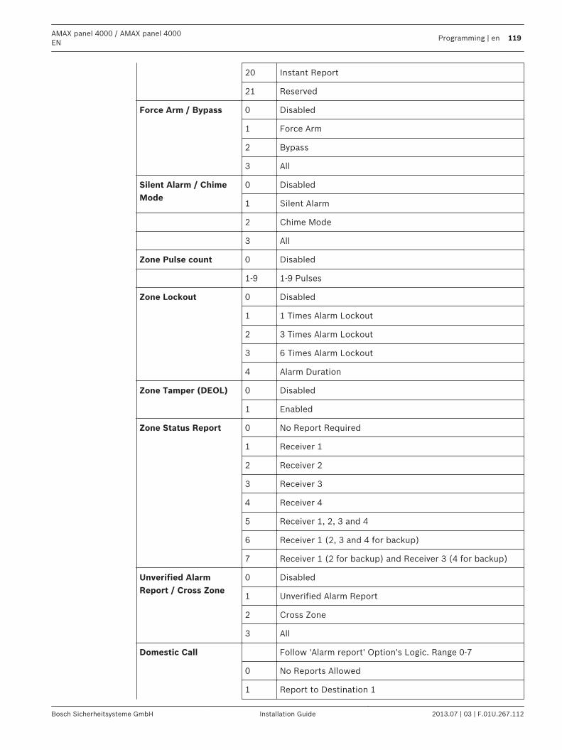
20 Instant Report
21 Reserved
Force Arm / Bypass 0 Disabled
1 Force Arm
2 Bypass
3 All
Silent Alarm / ChimeMode
0 Disabled
1 Silent Alarm
2 Chime Mode
3 All
Zone Pulse count 0 Disabled
1-9 1-9 Pulses
Zone Lockout 0 Disabled
1 1 Times Alarm Lockout
2 3 Times Alarm Lockout
3 6 Times Alarm Lockout
4 Alarm Duration
Zone Tamper (DEOL) 0 Disabled
1 Enabled
Zone Status Report 0 No Report Required
1 Receiver 1
2 Receiver 2
3 Receiver 3
4 Receiver 4
5 Receiver 1, 2, 3 and 4
6 Receiver 1 (2, 3 and 4 for backup)
7 Receiver 1 (2 for backup) and Receiver 3 (4 for backup)
Unverified AlarmReport / Cross Zone
0 Disabled
1 Unverified Alarm Report
2 Cross Zone
3 All
Domestic Call Follow 'Alarm report' Option's Logic. Range 0-7
0 No Reports Allowed
1 Report to Destination 1
AMAX panel 4000 / AMAX panel 4000EN
Programming | en 119
Bosch Sicherheitsysteme GmbH Installation Guide 2013.07 | 03 | F.01U.267.112
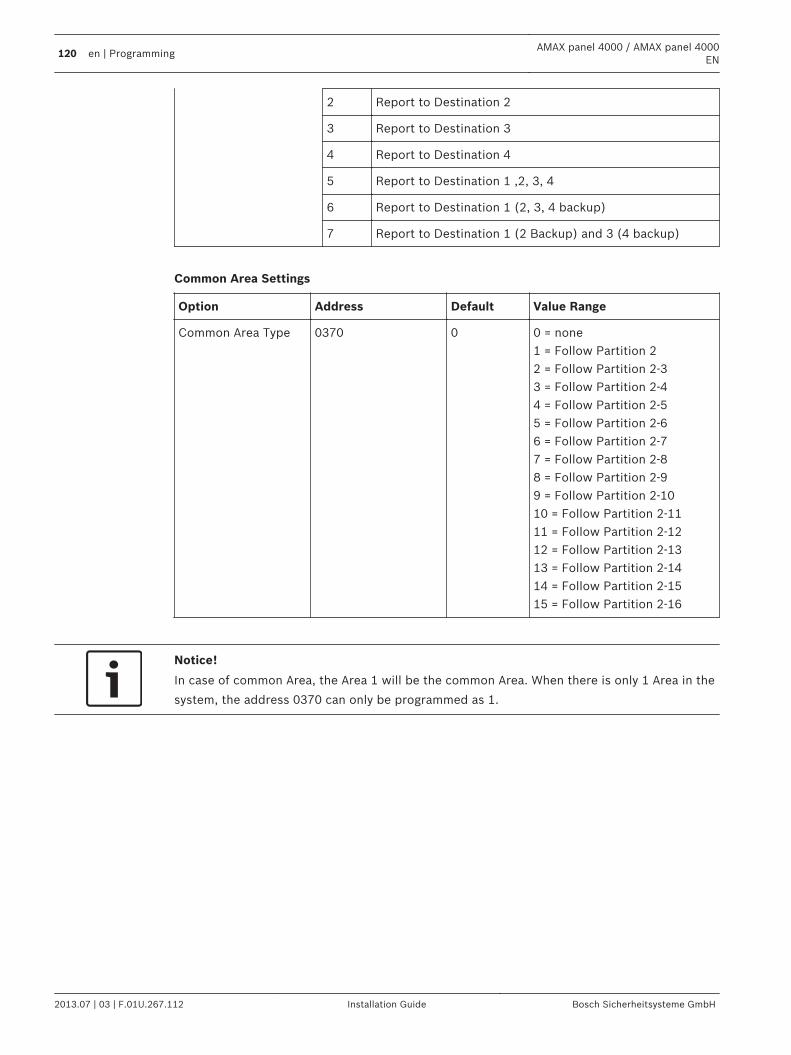
2 Report to Destination 2
3 Report to Destination 3
4 Report to Destination 4
5 Report to Destination 1 ,2, 3, 4
6 Report to Destination 1 (2, 3, 4 backup)
7 Report to Destination 1 (2 Backup) and 3 (4 backup)
Common Area Settings
Option Address Default Value Range
Common Area Type 0370 0 0 = none1 = Follow Partition 22 = Follow Partition 2-33 = Follow Partition 2-44 = Follow Partition 2-55 = Follow Partition 2-66 = Follow Partition 2-77 = Follow Partition 2-88 = Follow Partition 2-99 = Follow Partition 2-1010 = Follow Partition 2-1111 = Follow Partition 2-1212 = Follow Partition 2-1313 = Follow Partition 2-1414 = Follow Partition 2-1515 = Follow Partition 2-16
Notice!
In case of common Area, the Area 1 will be the common Area. When there is only 1 Area in the
system, the address 0370 can only be programmed as 1.
120 en | ProgrammingAMAX panel 4000 / AMAX panel 4000
EN
2013.07 | 03 | F.01U.267.112 Installation Guide Bosch Sicherheitsysteme GmbH
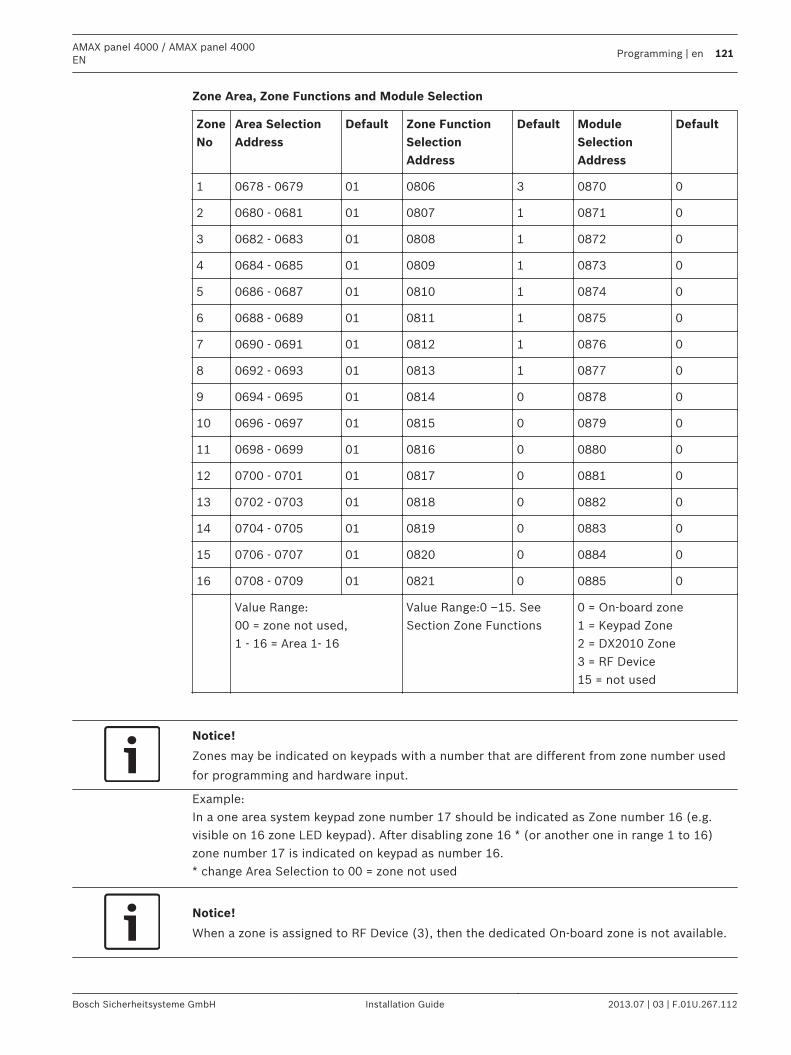
Zone Area, Zone Functions and Module Selection
ZoneNo
Area SelectionAddress
Default Zone FunctionSelectionAddress
Default ModuleSelectionAddress
Default
1 0678 - 0679 01 0806 3 0870 0
2 0680 - 0681 01 0807 1 0871 0
3 0682 - 0683 01 0808 1 0872 0
4 0684 - 0685 01 0809 1 0873 0
5 0686 - 0687 01 0810 1 0874 0
6 0688 - 0689 01 0811 1 0875 0
7 0690 - 0691 01 0812 1 0876 0
8 0692 - 0693 01 0813 1 0877 0
9 0694 - 0695 01 0814 0 0878 0
10 0696 - 0697 01 0815 0 0879 0
11 0698 - 0699 01 0816 0 0880 0
12 0700 - 0701 01 0817 0 0881 0
13 0702 - 0703 01 0818 0 0882 0
14 0704 - 0705 01 0819 0 0883 0
15 0706 - 0707 01 0820 0 0884 0
16 0708 - 0709 01 0821 0 0885 0
Value Range:00 = zone not used,1 - 16 = Area 1- 16
Value Range:0 –15. SeeSection Zone Functions
0 = On-board zone1 = Keypad Zone2 = DX2010 Zone3 = RF Device15 = not used
Notice!
Zones may be indicated on keypads with a number that are different from zone number used
for programming and hardware input.
Example:In a one area system keypad zone number 17 should be indicated as Zone number 16 (e.g.visible on 16 zone LED keypad). After disabling zone 16 * (or another one in range 1 to 16)zone number 17 is indicated on keypad as number 16.* change Area Selection to 00 = zone not used
Notice!
When a zone is assigned to RF Device (3), then the dedicated On-board zone is not available.
AMAX panel 4000 / AMAX panel 4000EN
Programming | en 121
Bosch Sicherheitsysteme GmbH Installation Guide 2013.07 | 03 | F.01U.267.112
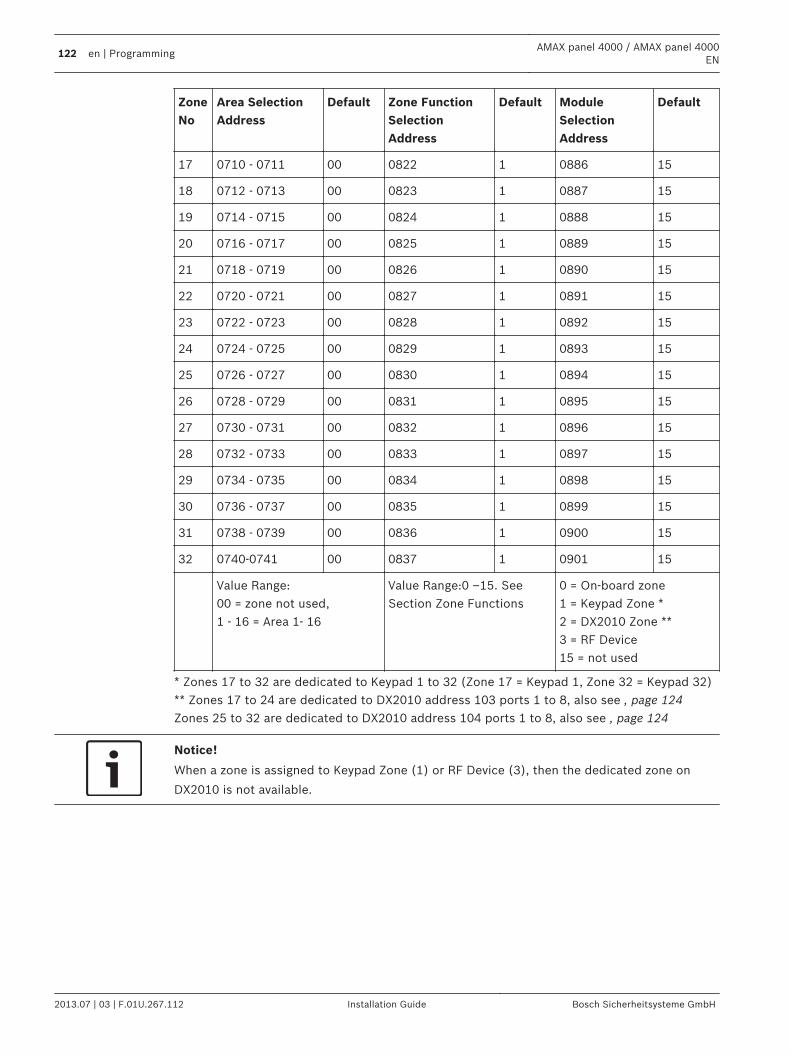
ZoneNo
Area SelectionAddress
Default Zone FunctionSelectionAddress
Default ModuleSelectionAddress
Default
17 0710 - 0711 00 0822 1 0886 15
18 0712 - 0713 00 0823 1 0887 15
19 0714 - 0715 00 0824 1 0888 15
20 0716 - 0717 00 0825 1 0889 15
21 0718 - 0719 00 0826 1 0890 15
22 0720 - 0721 00 0827 1 0891 15
23 0722 - 0723 00 0828 1 0892 15
24 0724 - 0725 00 0829 1 0893 15
25 0726 - 0727 00 0830 1 0894 15
26 0728 - 0729 00 0831 1 0895 15
27 0730 - 0731 00 0832 1 0896 15
28 0732 - 0733 00 0833 1 0897 15
29 0734 - 0735 00 0834 1 0898 15
30 0736 - 0737 00 0835 1 0899 15
31 0738 - 0739 00 0836 1 0900 15
32 0740-0741 00 0837 1 0901 15
Value Range:00 = zone not used,1 - 16 = Area 1- 16
Value Range:0 –15. SeeSection Zone Functions
0 = On-board zone1 = Keypad Zone *2 = DX2010 Zone **3 = RF Device15 = not used
* Zones 17 to 32 are dedicated to Keypad 1 to 32 (Zone 17 = Keypad 1, Zone 32 = Keypad 32)** Zones 17 to 24 are dedicated to DX2010 address 103 ports 1 to 8, also see , page 124Zones 25 to 32 are dedicated to DX2010 address 104 ports 1 to 8, also see , page 124
Notice!
When a zone is assigned to Keypad Zone (1) or RF Device (3), then the dedicated zone on
DX2010 is not available.
122 en | ProgrammingAMAX panel 4000 / AMAX panel 4000
EN
2013.07 | 03 | F.01U.267.112 Installation Guide Bosch Sicherheitsysteme GmbH
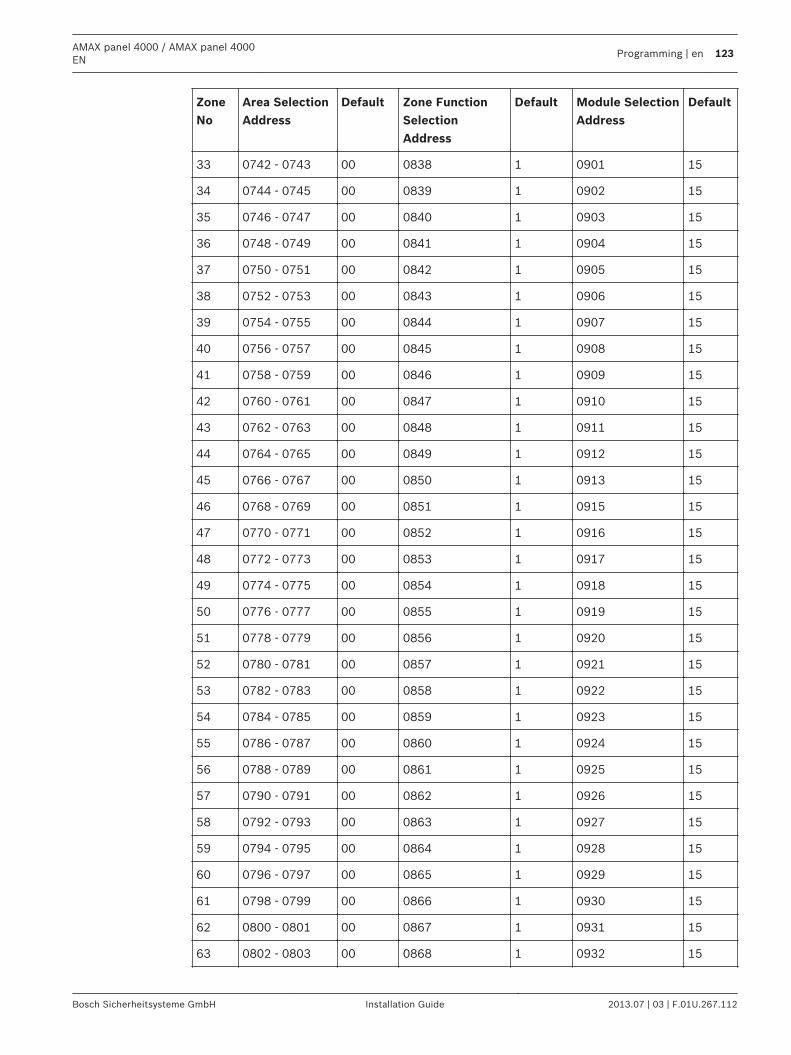
ZoneNo
Area SelectionAddress
Default Zone FunctionSelectionAddress
Default Module SelectionAddress
Default
33 0742 - 0743 00 0838 1 0901 15
34 0744 - 0745 00 0839 1 0902 15
35 0746 - 0747 00 0840 1 0903 15
36 0748 - 0749 00 0841 1 0904 15
37 0750 - 0751 00 0842 1 0905 15
38 0752 - 0753 00 0843 1 0906 15
39 0754 - 0755 00 0844 1 0907 15
40 0756 - 0757 00 0845 1 0908 15
41 0758 - 0759 00 0846 1 0909 15
42 0760 - 0761 00 0847 1 0910 15
43 0762 - 0763 00 0848 1 0911 15
44 0764 - 0765 00 0849 1 0912 15
45 0766 - 0767 00 0850 1 0913 15
46 0768 - 0769 00 0851 1 0915 15
47 0770 - 0771 00 0852 1 0916 15
48 0772 - 0773 00 0853 1 0917 15
49 0774 - 0775 00 0854 1 0918 15
50 0776 - 0777 00 0855 1 0919 15
51 0778 - 0779 00 0856 1 0920 15
52 0780 - 0781 00 0857 1 0921 15
53 0782 - 0783 00 0858 1 0922 15
54 0784 - 0785 00 0859 1 0923 15
55 0786 - 0787 00 0860 1 0924 15
56 0788 - 0789 00 0861 1 0925 15
57 0790 - 0791 00 0862 1 0926 15
58 0792 - 0793 00 0863 1 0927 15
59 0794 - 0795 00 0864 1 0928 15
60 0796 - 0797 00 0865 1 0929 15
61 0798 - 0799 00 0866 1 0930 15
62 0800 - 0801 00 0867 1 0931 15
63 0802 - 0803 00 0868 1 0932 15
AMAX panel 4000 / AMAX panel 4000EN
Programming | en 123
Bosch Sicherheitsysteme GmbH Installation Guide 2013.07 | 03 | F.01U.267.112
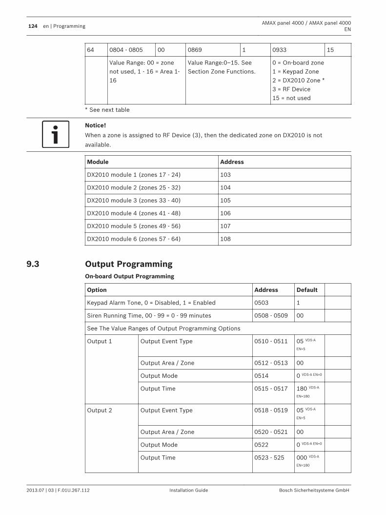
64 0804 - 0805 00 0869 1 0933 15
Value Range: 00 = zonenot used, 1 - 16 = Area 1-16
Value Range:0–15. SeeSection Zone Functions.
0 = On-board zone1 = Keypad Zone2 = DX2010 Zone *3 = RF Device15 = not used
* See next table
Notice!
When a zone is assigned to RF Device (3), then the dedicated zone on DX2010 is not
available.
Module Address
DX2010 module 1 (zones 17 - 24) 103
DX2010 module 2 (zones 25 - 32) 104
DX2010 module 3 (zones 33 - 40) 105
DX2010 module 4 (zones 41 - 48) 106
DX2010 module 5 (zones 49 - 56) 107
DX2010 module 6 (zones 57 - 64) 108
Output ProgrammingOn-board Output Programming
Option Address Default
Keypad Alarm Tone, 0 = Disabled, 1 = Enabled 0503 1
Siren Running Time, 00 - 99 = 0 - 99 minutes 0508 - 0509 00
See The Value Ranges of Output Programming Options
Output 1 Output Event Type 0510 - 0511 05 VDS-A
EN=5
Output Area / Zone 0512 - 0513 00
Output Mode 0514 0 VDS-A EN=0
Output Time 0515 - 0517 180 VDS-A
EN=180
Output 2 Output Event Type 0518 - 0519 05 VDS-A
EN=5
Output Area / Zone 0520 - 0521 00
Output Mode 0522 0 VDS-A EN=0
Output Time 0523 - 525 000 VDS-A
EN=180
9.3
124 en | ProgrammingAMAX panel 4000 / AMAX panel 4000
EN
2013.07 | 03 | F.01U.267.112 Installation Guide Bosch Sicherheitsysteme GmbH
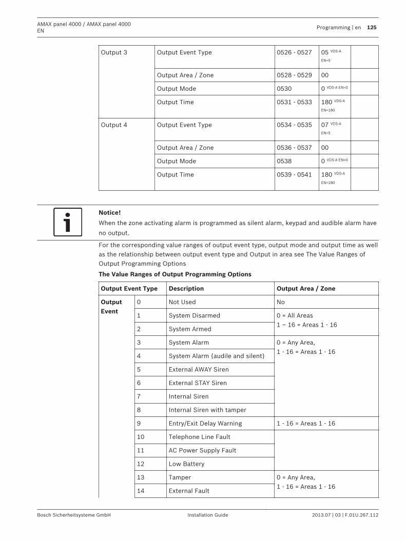
Output 3 Output Event Type 0526 - 0527 05 VDS-A
EN=5
Output Area / Zone 0528 - 0529 00
Output Mode 0530 0 VDS-A EN=0
Output Time 0531 - 0533 180 VDS-A
EN=180
Output 4 Output Event Type 0534 - 0535 07 VDS-A
EN=5
Output Area / Zone 0536 - 0537 00
Output Mode 0538 0 VDS-A EN=0
Output Time 0539 - 0541 180 VDS-A
EN=180
Notice!
When the zone activating alarm is programmed as silent alarm, keypad and audible alarm have
no output.
For the corresponding value ranges of output event type, output mode and output time as wellas the relationship between output event type and Output in area see The Value Ranges ofOutput Programming Options
The Value Ranges of Output Programming Options
Output Event Type Description Output Area / Zone
OutputEvent
0 Not Used No
1 System Disarmed 0 = All Areas1 – 16 = Areas 1 - 16
2 System Armed
3 System Alarm 0 = Any Area,1 - 16 = Areas 1 - 16
4 System Alarm (audile and silent)
5 External AWAY Siren
6 External STAY Siren
7 Internal Siren
8 Internal Siren with tamper
9 Entry/Exit Delay Warning 1 - 16 = Areas 1 - 16
10 Telephone Line Fault
11 AC Power Supply Fault
12 Low Battery
13 Tamper 0 = Any Area,1 - 16 = Areas 1 - 16
14 External Fault
AMAX panel 4000 / AMAX panel 4000EN
Programming | en 125
Bosch Sicherheitsysteme GmbH Installation Guide 2013.07 | 03 | F.01U.267.112
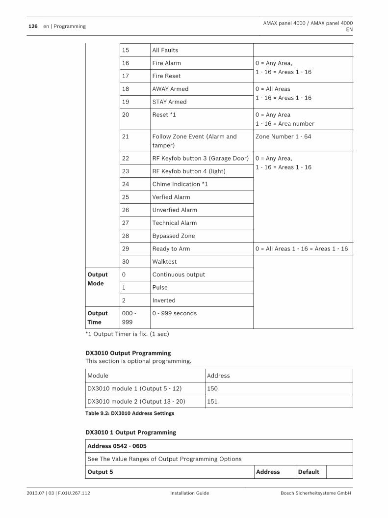
15 All Faults
16 Fire Alarm 0 = Any Area,1 - 16 = Areas 1 - 16
17 Fire Reset
18 AWAY Armed 0 = All Areas1 - 16 = Areas 1 - 16
19 STAY Armed
20 Reset *1 0 = Any Area1 - 16 = Area number
21 Follow Zone Event (Alarm andtamper)
Zone Number 1 - 64
22 RF Keyfob button 3 (Garage Door) 0 = Any Area,1 - 16 = Areas 1 - 16
23 RF Keyfob button 4 (light)
24 Chime Indication *1
25 Verfied Alarm
26 Unverfied Alarm
27 Technical Alarm
28 Bypassed Zone
29 Ready to Arm 0 = All Areas 1 - 16 = Areas 1 - 16
30 Walktest
OutputMode
0 Continuous output
1 Pulse
2 Inverted
OutputTime
000 -999
0 - 999 seconds
*1 Output Timer is fix. (1 sec)
DX3010 Output ProgrammingThis section is optional programming.
Module Address
DX3010 module 1 (Output 5 - 12) 150
DX3010 module 2 (Output 13 - 20) 151
Table 9.2: DX3010 Address Settings
DX3010 1 Output Programming
Address 0542 - 0605
See The Value Ranges of Output Programming Options
Output 5 Address Default
126 en | ProgrammingAMAX panel 4000 / AMAX panel 4000
EN
2013.07 | 03 | F.01U.267.112 Installation Guide Bosch Sicherheitsysteme GmbH
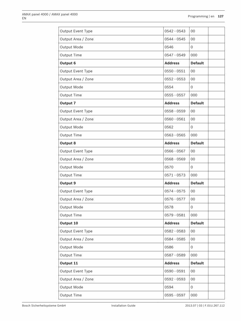
Output Event Type 0542 - 0543 00
Output Area / Zone 0544 - 0545 00
Output Mode 0546 0
Output Time 0547 - 0549 000
Output 6 Address Default
Output Event Type 0550 - 0551 00
Output Area / Zone 0552 - 0553 00
Output Mode 0554 0
Output Time 0555 - 0557 000
Output 7 Address Default
Output Event Type 0558 - 0559 00
Output Area / Zone 0560 - 0561 00
Output Mode 0562 0
Output Time 0563 - 0565 000
Output 8 Address Default
Output Event Type 0566 - 0567 00
Output Area / Zone 0568 - 0569 00
Output Mode 0570 0
Output Time 0571 - 0573 000
Output 9 Address Default
Output Event Type 0574 - 0575 00
Output Area / Zone 0576 - 0577 00
Output Mode 0578 0
Output Time 0579 - 0581 000
Output 10 Address Default
Output Event Type 0582 - 0583 00
Output Area / Zone 0584 - 0585 00
Output Mode 0586 0
Output Time 0587 - 0589 000
Output 11 Address Default
Output Event Type 0590 - 0591 00
Output Area / Zone 0592 - 0593 00
Output Mode 0594 0
Output Time 0595 - 0597 000
AMAX panel 4000 / AMAX panel 4000EN
Programming | en 127
Bosch Sicherheitsysteme GmbH Installation Guide 2013.07 | 03 | F.01U.267.112
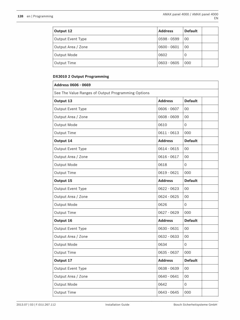
Output 12 Address Default
Output Event Type 0598 - 0599 00
Output Area / Zone 0600 - 0601 00
Output Mode 0602 0
Output Time 0603 - 0605 000
DX3010 2 Output Programming
Address 0606 - 0669
See The Value Ranges of Output Programming Options
Output 13 Address Default
Output Event Type 0606 - 0607 00
Output Area / Zone 0608 - 0609 00
Output Mode 0610 0
Output Time 0611 - 0613 000
Output 14 Address Default
Output Event Type 0614 - 0615 00
Output Area / Zone 0616 - 0617 00
Output Mode 0618 0
Output Time 0619 - 0621 000
Output 15 Address Default
Output Event Type 0622 - 0623 00
Output Area / Zone 0624 - 0625 00
Output Mode 0626 0
Output Time 0627 - 0629 000
Output 16 Address Default
Output Event Type 0630 - 0631 00
Output Area / Zone 0632 - 0633 00
Output Mode 0634 0
Output Time 0635 - 0637 000
Output 17 Address Default
Output Event Type 0638 - 0639 00
Output Area / Zone 0640 - 0641 00
Output Mode 0642 0
Output Time 0643 - 0645 000
128 en | ProgrammingAMAX panel 4000 / AMAX panel 4000
EN
2013.07 | 03 | F.01U.267.112 Installation Guide Bosch Sicherheitsysteme GmbH
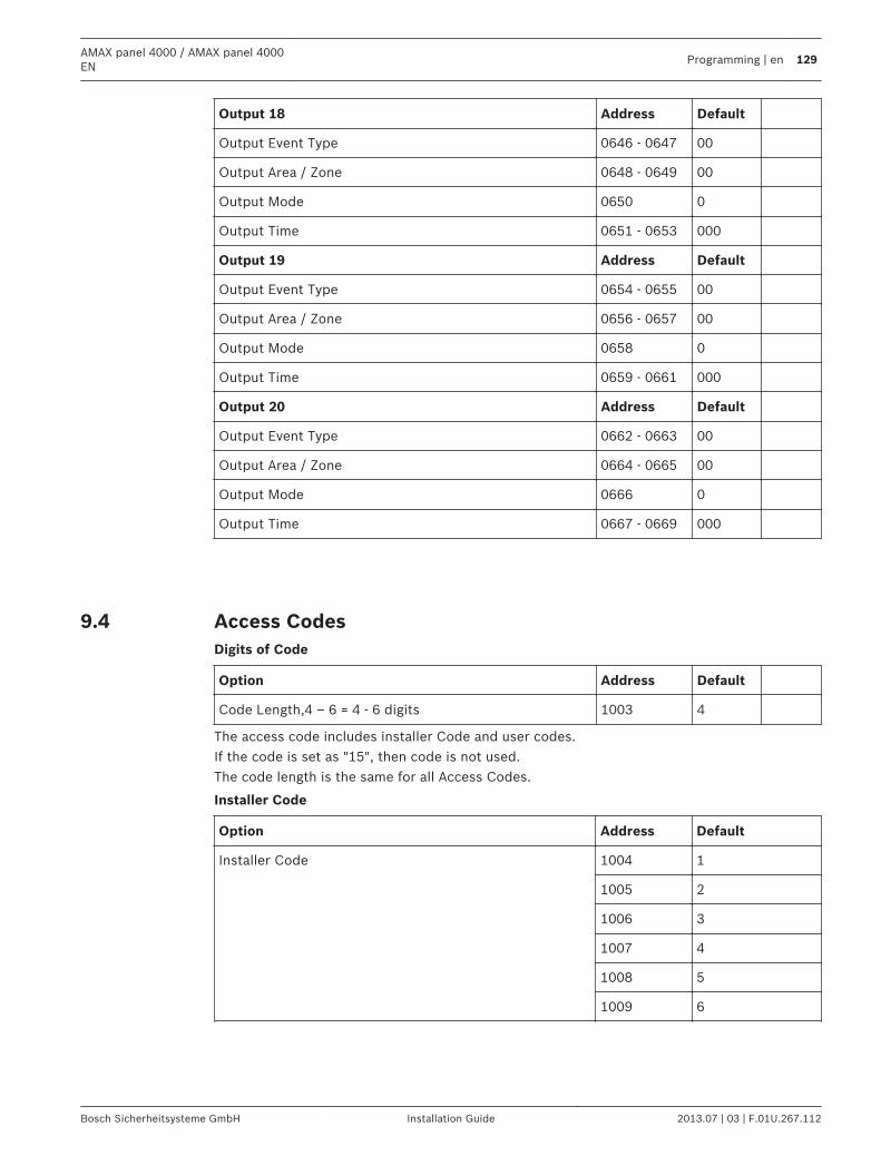
Output 18 Address Default
Output Event Type 0646 - 0647 00
Output Area / Zone 0648 - 0649 00
Output Mode 0650 0
Output Time 0651 - 0653 000
Output 19 Address Default
Output Event Type 0654 - 0655 00
Output Area / Zone 0656 - 0657 00
Output Mode 0658 0
Output Time 0659 - 0661 000
Output 20 Address Default
Output Event Type 0662 - 0663 00
Output Area / Zone 0664 - 0665 00
Output Mode 0666 0
Output Time 0667 - 0669 000
Access CodesDigits of Code
Option Address Default
Code Length,4 – 6 = 4 - 6 digits 1003 4
The access code includes installer Code and user codes.If the code is set as "15", then code is not used.The code length is the same for all Access Codes.
Installer Code
Option Address Default
Installer Code 1004 1
1005 2
1006 3
1007 4
1008 5
1009 6
9.4
AMAX panel 4000 / AMAX panel 4000EN
Programming | en 129
Bosch Sicherheitsysteme GmbH Installation Guide 2013.07 | 03 | F.01U.267.112
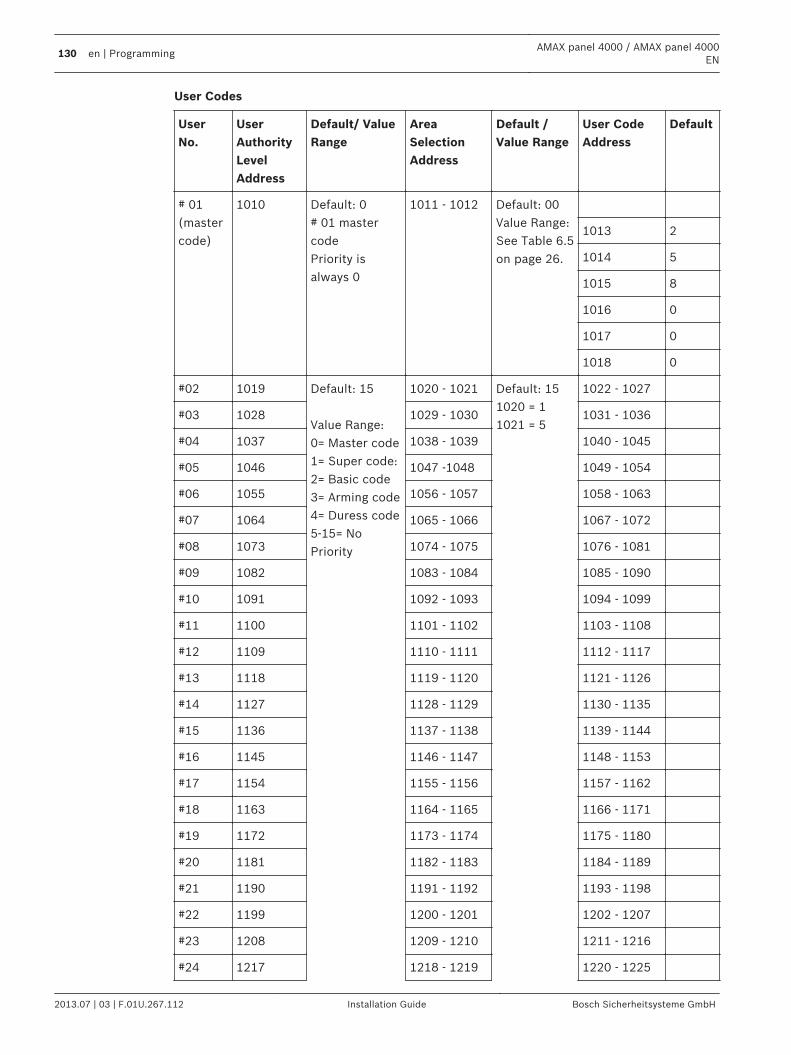
User Codes
UserNo.
UserAuthorityLevelAddress
Default/ ValueRange
AreaSelectionAddress
Default /Value Range
User CodeAddress
Default
# 01(mastercode)
1010 Default: 0# 01 mastercodePriority isalways 0
1011 - 1012 Default: 00Value Range:See Table 6.5on page 26.
1013 2
1014 5
1015 8
1016 0
1017 0
1018 0
#02 1019 Default: 15 Value Range:0= Master code1= Super code:2= Basic code3= Arming code4= Duress code5-15= NoPriority
1020 - 1021 Default: 151020 = 11021 = 5
1022 - 1027
#03 1028 1029 - 1030 1031 - 1036
#04 1037 1038 - 1039 1040 - 1045
#05 1046 1047 -1048 1049 - 1054
#06 1055 1056 - 1057 1058 - 1063
#07 1064 1065 - 1066 1067 - 1072
#08 1073 1074 - 1075 1076 - 1081
#09 1082 1083 - 1084 1085 - 1090
#10 1091 1092 - 1093 1094 - 1099
#11 1100 1101 - 1102 1103 - 1108
#12 1109 1110 - 1111 1112 - 1117
#13 1118 1119 - 1120 1121 - 1126
#14 1127 1128 - 1129 1130 - 1135
#15 1136 1137 - 1138 1139 - 1144
#16 1145 1146 - 1147 1148 - 1153
#17 1154 1155 - 1156 1157 - 1162
#18 1163 1164 - 1165 1166 - 1171
#19 1172 1173 - 1174 1175 - 1180
#20 1181 1182 - 1183 1184 - 1189
#21 1190 1191 - 1192 1193 - 1198
#22 1199 1200 - 1201 1202 - 1207
#23 1208 1209 - 1210 1211 - 1216
#24 1217 1218 - 1219 1220 - 1225
130 en | ProgrammingAMAX panel 4000 / AMAX panel 4000
EN
2013.07 | 03 | F.01U.267.112 Installation Guide Bosch Sicherheitsysteme GmbH
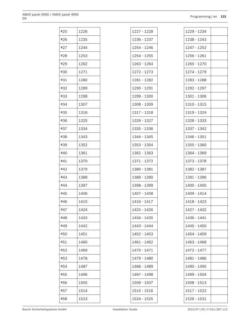
#25 1226 1227 - 1228 1229 - 1234
#26 1235 1236 - 1237 1238 - 1243
#27 1244 1254 - 1246 1247 - 1252
#28 1253 1254 - 1255 1256 - 1261
#29 1262 1263 - 1264 1265 - 1270
#30 1271 1272 - 1273 1274 - 1279
#31 1280 1281 - 1282 1283 - 1288
#32 1289 1290 - 1291 1292 - 1297
#33 1298 1299 - 1300 1301 - 1306
#34 1307 1308 - 1309 1310 - 1315
#35 1316 1317 - 1318 1319 - 1324
#36 1325 1326 - 1327 1328 - 1333
#37 1334 1335 - 1336 1337 - 1342
#38 1343 1344 - 1345 1346 - 1351
#39 1352 1353 - 1354 1355 - 1360
#40 1361 1362 - 1363 1364 - 1369
#41 1370 1371 - 1372 1373 - 1378
#42 1379 1380 - 1381 1382 - 1387
#43 1388 1389 - 1390 1391 - 1396
#44 1397 1398 - 1399 1400 - 1405
#45 1406 1407 - 1408 1409 - 1414
#46 1415 1416 - 1417 1418 - 1423
#47 1424 1425 - 1426 1427 - 1432
#48 1433 1434 - 1435 1436 - 1441
#49 1442 1443 - 1444 1445 - 1450
#50 1451 1452 - 1453 1454 - 1459
#51 1460 1461 - 1462 1463 - 1468
#52 1469 1470 - 1471 1472 - 1477
#53 1478 1479 - 1480 1481 - 1486
#54 1487 1488 - 1489 1490 - 1495
#55 1496 1497 - 1498 1499 - 1504
#56 1505 1506 - 1507 1508 - 1513
#57 1514 1515 - 1516 1517 - 1522
#58 1523 1524 - 1525 1526 - 1531
AMAX panel 4000 / AMAX panel 4000EN
Programming | en 131
Bosch Sicherheitsysteme GmbH Installation Guide 2013.07 | 03 | F.01U.267.112
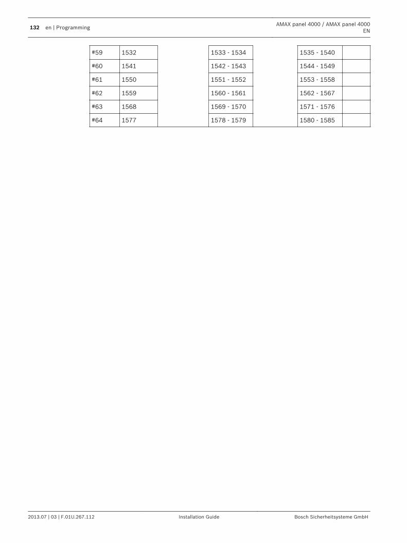
#59 1532 1533 - 1534 1535 - 1540
#60 1541 1542 - 1543 1544 - 1549
#61 1550 1551 - 1552 1553 - 1558
#62 1559 1560 - 1561 1562 - 1567
#63 1568 1569 - 1570 1571 - 1576
#64 1577 1578 - 1579 1580 - 1585
132 en | ProgrammingAMAX panel 4000 / AMAX panel 4000
EN
2013.07 | 03 | F.01U.267.112 Installation Guide Bosch Sicherheitsysteme GmbH
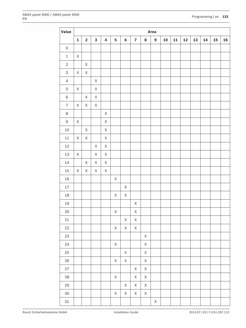
Value Area
1 2 3 4 5 6 7 8 9 10 11 12 13 14 15 16
0
1 X
2 X
3 X X
4 X
5 X X
6 X X
7 X X X
8 X
9 X X
10 X X
11 X X X
12 X X
13 X X X
14 X X X
15 X X X X
16 X
17 X
18 X X
19 X
20 X X
21 X X
22 X X X
23 X
24 X X
25 X X
26 X X X
27 X X
28 X X X
29 X X X
30 X X X X
31 X
AMAX panel 4000 / AMAX panel 4000EN
Programming | en 133
Bosch Sicherheitsysteme GmbH Installation Guide 2013.07 | 03 | F.01U.267.112
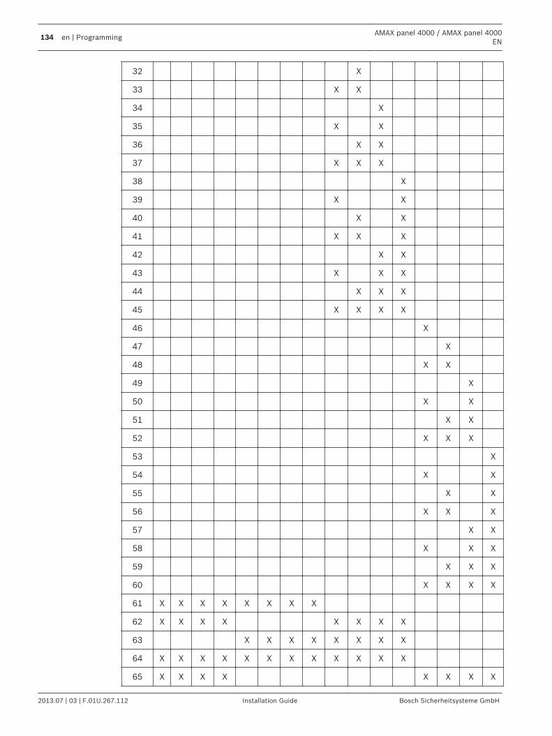
32 X
33 X X
34 X
35 X X
36 X X
37 X X X
38 X
39 X X
40 X X
41 X X X
42 X X
43 X X X
44 X X X
45 X X X X
46 X
47 X
48 X X
49 X
50 X X
51 X X
52 X X X
53 X
54 X X
55 X X
56 X X X
57 X X
58 X X X
59 X X X
60 X X X X
61 X X X X X X X X
62 X X X X X X X X
63 X X X X X X X X
64 X X X X X X X X X X X X
65 X X X X X X X X
134 en | ProgrammingAMAX panel 4000 / AMAX panel 4000
EN
2013.07 | 03 | F.01U.267.112 Installation Guide Bosch Sicherheitsysteme GmbH
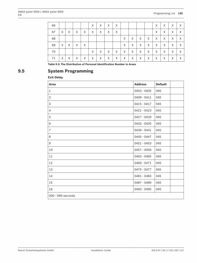
66 X X X X X X X X
67 X X X X X X X X X X X X
68 X X X X X X X X
69 X X X X X X X X X X X X
70 X X X X X X X X X X X X
71 X X X X X X X X X X X X X X X X
Table 9.3: The Distribution of Personal Identification Number in Areas
System ProgrammingExit Delay
Area Address Default
1 0403 - 0405 045
2 0409 - 0411 045
3 0415 - 0417 045
4 0421 - 0423 045
5 0427 - 0429 045
6 0433 - 0435 045
7 0439 - 0441 045
8 0445 - 0447 045
9 0451 - 0453 045
10 0457 - 0459 045
11 0463 - 0465 045
12 0469 - 0471 045
13 0475 - 0477 045
14 0481 - 0483 045
15 0487 - 0489 045
16 0493 - 0495 045
000 - 999 seconds
9.5
AMAX panel 4000 / AMAX panel 4000EN
Programming | en 135
Bosch Sicherheitsysteme GmbH Installation Guide 2013.07 | 03 | F.01U.267.112
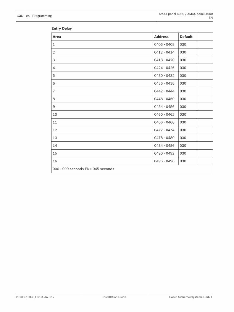
Entry Delay
Area Address Default
1 0406 - 0408 030
2 0412 - 0414 030
3 0418 - 0420 030
4 0424 - 0426 030
5 0430 - 0432 030
6 0436 - 0438 030
7 0442 - 0444 030
8 0448 - 0450 030
9 0454 - 0456 030
10 0460 - 0462 030
11 0466 - 0468 030
12 0472 - 0474 030
13 0478 - 0480 030
14 0484 - 0486 030
15 0490 - 0492 030
16 0496 - 0498 030
000 - 999 seconds EN= 045 seconds
136 en | ProgrammingAMAX panel 4000 / AMAX panel 4000
EN
2013.07 | 03 | F.01U.267.112 Installation Guide Bosch Sicherheitsysteme GmbH
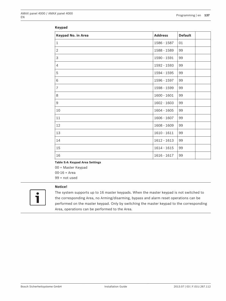
Keypad
Keypad No. in Area Address Default
1 1586 - 1587 01
2 1588 - 1589 99
3 1590 - 1591 99
4 1592 - 1593 99
5 1594 - 1595 99
6 1596 - 1597 99
7 1598 - 1599 99
8 1600 - 1601 99
9 1602 - 1603 99
10 1604 - 1605 99
11 1606 - 1607 99
12 1608 - 1609 99
13 1610 - 1611 99
14 1612 - 1613 99
15 1614 - 1615 99
16 1616 - 1617 99
Table 9.4: Keypad Area Settings
00 = Master Keypad00-16 = Area99 = not used
Notice!
The system supports up to 16 master keypads. When the master keypad is not switched to
the corresponding Area, no Arming/disarming, bypass and alarm reset operations can be
performed on the master keypad. Only by switching the master keypad to the corresponding
Area, operations can be performed to the Area.
AMAX panel 4000 / AMAX panel 4000EN
Programming | en 137
Bosch Sicherheitsysteme GmbH Installation Guide 2013.07 | 03 | F.01U.267.112
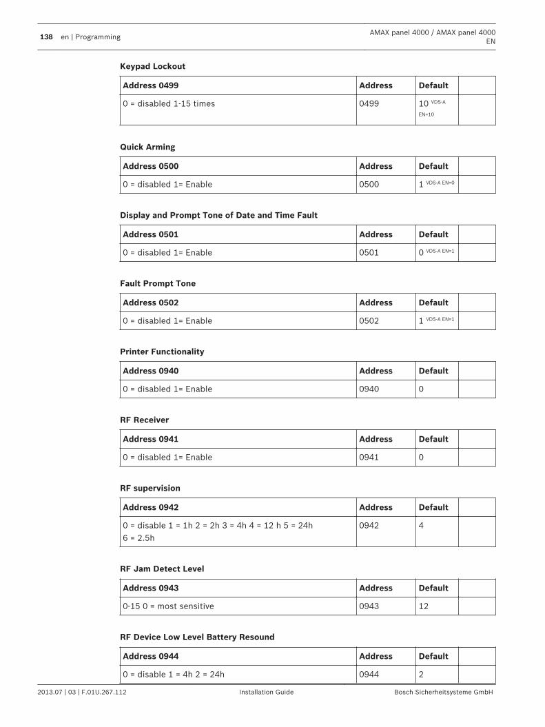
Keypad Lockout
Address 0499 Address Default
0 = disabled 1-15 times 0499 10 VDS-A
EN=10
Quick Arming
Address 0500 Address Default
0 = disabled 1= Enable 0500 1 VDS-A EN=0
Display and Prompt Tone of Date and Time Fault
Address 0501 Address Default
0 = disabled 1= Enable 0501 0 VDS-A EN=1
Fault Prompt Tone
Address 0502 Address Default
0 = disabled 1= Enable 0502 1 VDS-A EN=1
Printer Functionality
Address 0940 Address Default
0 = disabled 1= Enable 0940 0
RF Receiver
Address 0941 Address Default
0 = disabled 1= Enable 0941 0
RF supervision
Address 0942 Address Default
0 = disable 1 = 1h 2 = 2h 3 = 4h 4 = 12 h 5 = 24h6 = 2.5h
0942 4
RF Jam Detect Level
Address 0943 Address Default
0-15 0 = most sensitive 0943 12
RF Device Low Level Battery Resound
Address 0944 Address Default
0 = disable 1 = 4h 2 = 24h 0944 2
138 en | ProgrammingAMAX panel 4000 / AMAX panel 4000
EN
2013.07 | 03 | F.01U.267.112 Installation Guide Bosch Sicherheitsysteme GmbH
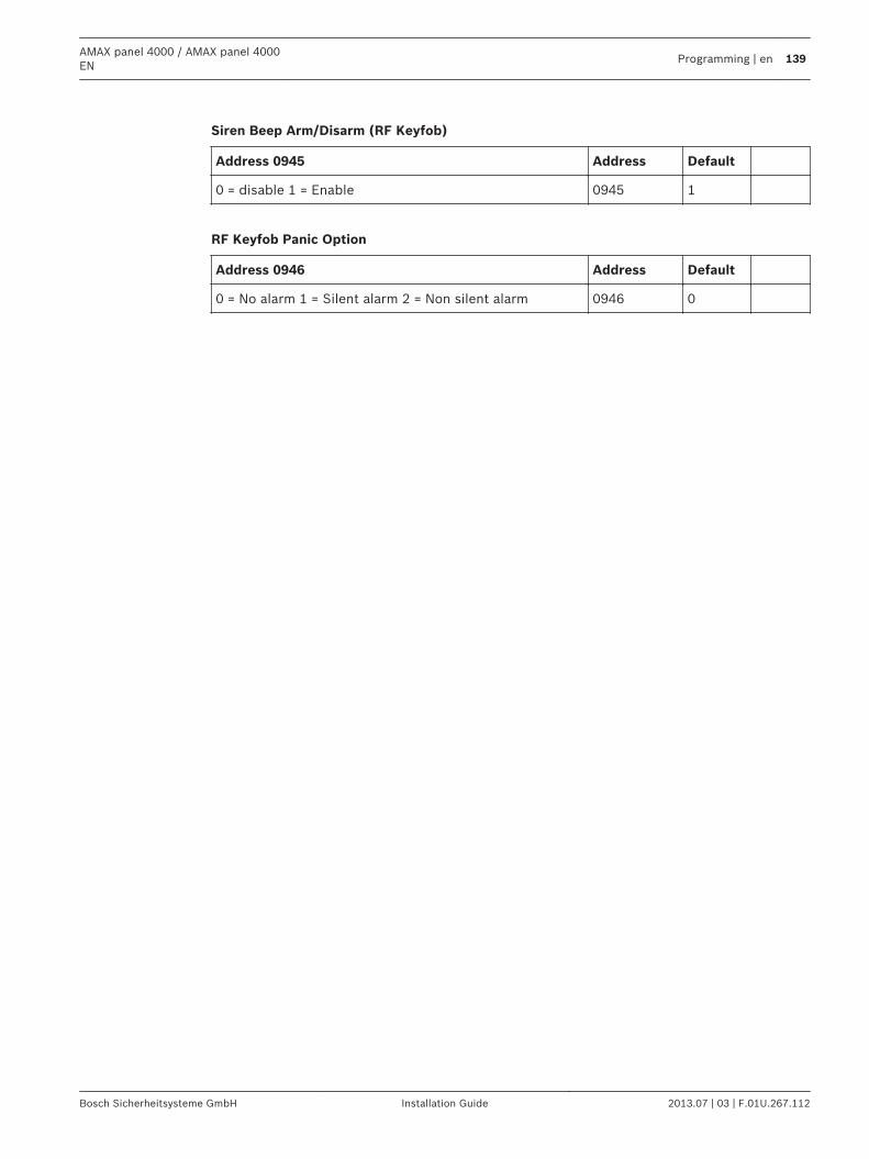
Siren Beep Arm/Disarm (RF Keyfob)
Address 0945 Address Default
0 = disable 1 = Enable 0945 1
RF Keyfob Panic Option
Address 0946 Address Default
0 = No alarm 1 = Silent alarm 2 = Non silent alarm 0946 0
AMAX panel 4000 / AMAX panel 4000EN
Programming | en 139
Bosch Sicherheitsysteme GmbH Installation Guide 2013.07 | 03 | F.01U.267.112
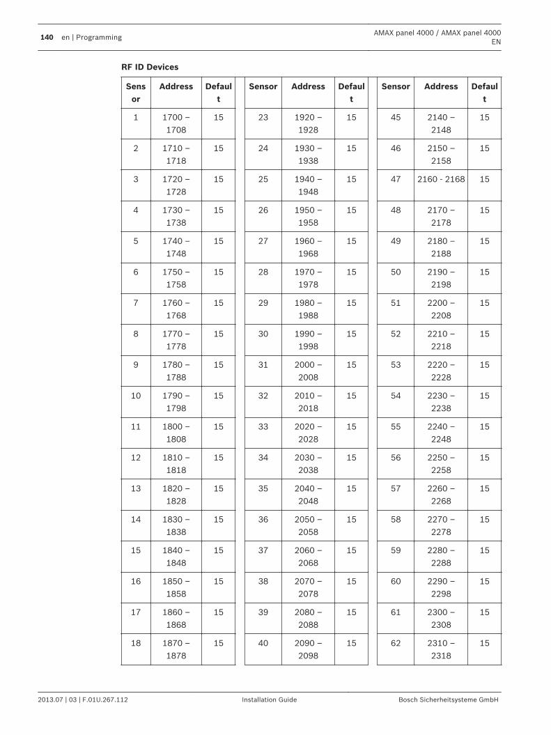
RF ID Devices
Sensor
Address Default
Sensor Address Default
Sensor Address Default
1 1700 –1708
15 23 1920 –1928
15 45 2140 –2148
15
2 1710 –1718
15 24 1930 –1938
15 46 2150 –2158
15
3 1720 –1728
15 25 1940 –1948
15 47 2160 - 2168 15
4 1730 –1738
15 26 1950 –1958
15 48 2170 –2178
15
5 1740 –1748
15 27 1960 –1968
15 49 2180 –2188
15
6 1750 –1758
15 28 1970 –1978
15 50 2190 –2198
15
7 1760 –1768
15 29 1980 –1988
15 51 2200 –2208
15
8 1770 –1778
15 30 1990 –1998
15 52 2210 –2218
15
9 1780 –1788
15 31 2000 –2008
15 53 2220 –2228
15
10 1790 –1798
15 32 2010 –2018
15 54 2230 –2238
15
11 1800 –1808
15 33 2020 –2028
15 55 2240 –2248
15
12 1810 –1818
15 34 2030 –2038
15 56 2250 –2258
15
13 1820 –1828
15 35 2040 –2048
15 57 2260 –2268
15
14 1830 –1838
15 36 2050 –2058
15 58 2270 –2278
15
15 1840 –1848
15 37 2060 –2068
15 59 2280 –2288
15
16 1850 –1858
15 38 2070 –2078
15 60 2290 –2298
15
17 1860 –1868
15 39 2080 –2088
15 61 2300 –2308
15
18 1870 –1878
15 40 2090 –2098
15 62 2310 –2318
15
140 en | ProgrammingAMAX panel 4000 / AMAX panel 4000
EN
2013.07 | 03 | F.01U.267.112 Installation Guide Bosch Sicherheitsysteme GmbH
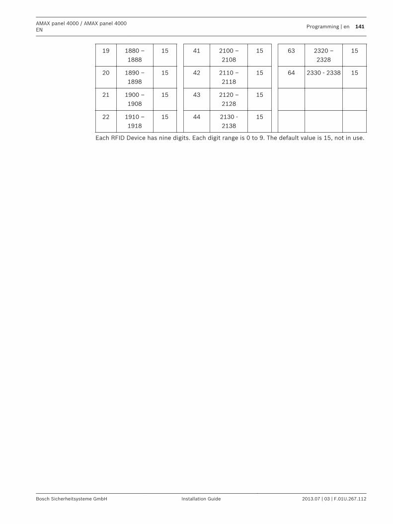
19 1880 –1888
15 41 2100 –2108
15 63 2320 –2328
15
20 1890 –1898
15 42 2110 –2118
15 64 2330 - 2338 15
21 1900 –1908
15 43 2120 –2128
15
22 1910 –1918
15 44 2130 -2138
15
Each RFID Device has nine digits. Each digit range is 0 to 9. The default value is 15, not in use.
AMAX panel 4000 / AMAX panel 4000EN
Programming | en 141
Bosch Sicherheitsysteme GmbH Installation Guide 2013.07 | 03 | F.01U.267.112
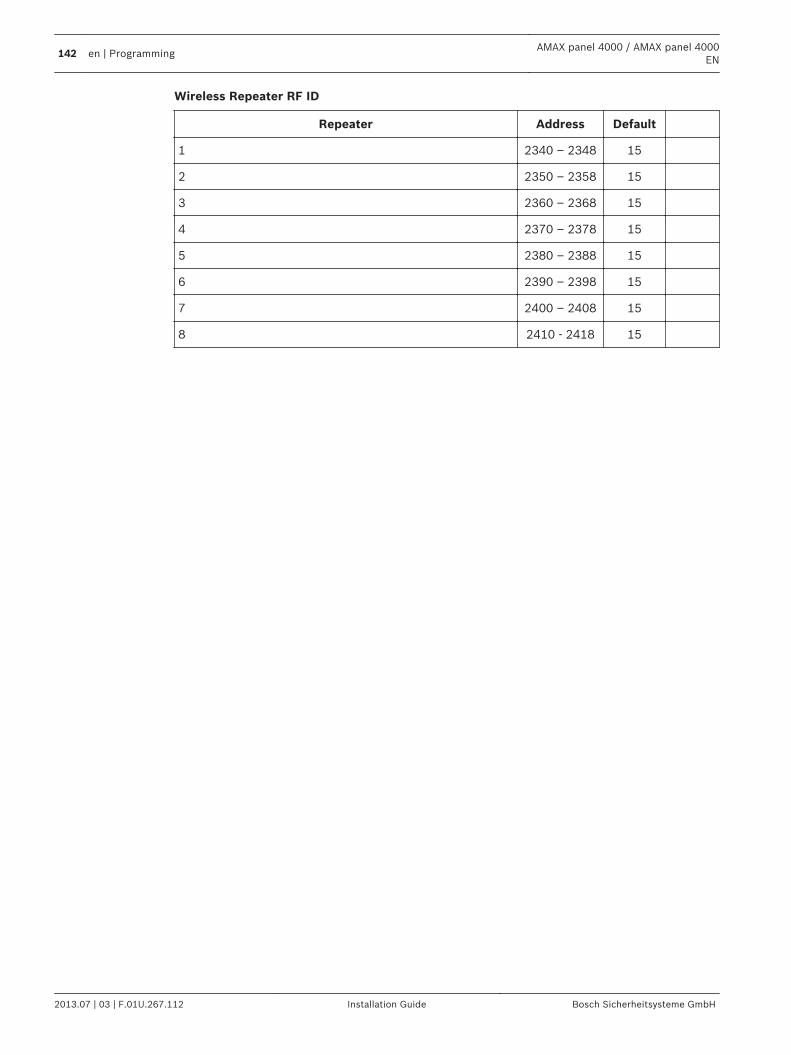
Wireless Repeater RF ID
Repeater Address Default
1 2340 – 2348 15
2 2350 – 2358 15
3 2360 – 2368 15
4 2370 – 2378 15
5 2380 – 2388 15
6 2390 – 2398 15
7 2400 – 2408 15
8 2410 - 2418 15
142 en | ProgrammingAMAX panel 4000 / AMAX panel 4000
EN
2013.07 | 03 | F.01U.267.112 Installation Guide Bosch Sicherheitsysteme GmbH
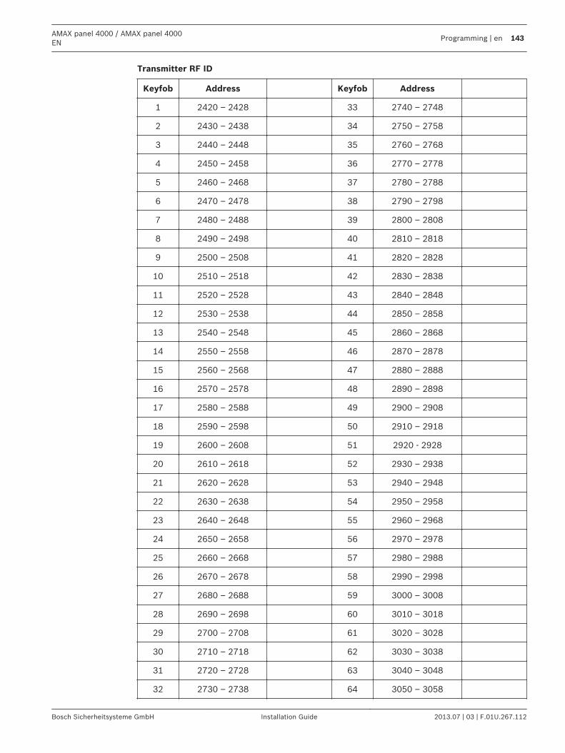
Transmitter RF ID
Keyfob Address Keyfob Address
1 2420 – 2428 33 2740 – 2748
2 2430 – 2438 34 2750 – 2758
3 2440 – 2448 35 2760 – 2768
4 2450 – 2458 36 2770 – 2778
5 2460 – 2468 37 2780 – 2788
6 2470 – 2478 38 2790 – 2798
7 2480 – 2488 39 2800 – 2808
8 2490 – 2498 40 2810 – 2818
9 2500 – 2508 41 2820 – 2828
10 2510 – 2518 42 2830 – 2838
11 2520 – 2528 43 2840 – 2848
12 2530 – 2538 44 2850 – 2858
13 2540 – 2548 45 2860 – 2868
14 2550 – 2558 46 2870 – 2878
15 2560 – 2568 47 2880 – 2888
16 2570 – 2578 48 2890 – 2898
17 2580 – 2588 49 2900 – 2908
18 2590 – 2598 50 2910 – 2918
19 2600 – 2608 51 2920 - 2928
20 2610 – 2618 52 2930 – 2938
21 2620 – 2628 53 2940 – 2948
22 2630 – 2638 54 2950 – 2958
23 2640 – 2648 55 2960 – 2968
24 2650 – 2658 56 2970 – 2978
25 2660 – 2668 57 2980 – 2988
26 2670 – 2678 58 2990 – 2998
27 2680 – 2688 59 3000 – 3008
28 2690 – 2698 60 3010 – 3018
29 2700 – 2708 61 3020 – 3028
30 2710 – 2718 62 3030 – 3038
31 2720 – 2728 63 3040 – 3048
32 2730 – 2738 64 3050 – 3058
AMAX panel 4000 / AMAX panel 4000EN
Programming | en 143
Bosch Sicherheitsysteme GmbH Installation Guide 2013.07 | 03 | F.01U.267.112
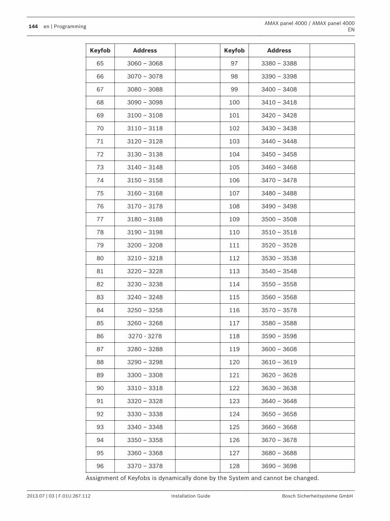
Keyfob Address Keyfob Address
65 3060 – 3068 97 3380 – 3388
66 3070 – 3078 98 3390 – 3398
67 3080 – 3088 99 3400 – 3408
68 3090 – 3098 100 3410 – 3418
69 3100 – 3108 101 3420 – 3428
70 3110 – 3118 102 3430 – 3438
71 3120 – 3128 103 3440 – 3448
72 3130 – 3138 104 3450 – 3458
73 3140 – 3148 105 3460 – 3468
74 3150 – 3158 106 3470 – 3478
75 3160 – 3168 107 3480 – 3488
76 3170 – 3178 108 3490 – 3498
77 3180 – 3188 109 3500 – 3508
78 3190 – 3198 110 3510 – 3518
79 3200 – 3208 111 3520 – 3528
80 3210 – 3218 112 3530 – 3538
81 3220 – 3228 113 3540 – 3548
82 3230 – 3238 114 3550 – 3558
83 3240 – 3248 115 3560 – 3568
84 3250 – 3258 116 3570 – 3578
85 3260 – 3268 117 3580 – 3588
86 3270 - 3278 118 3590 – 3598
87 3280 – 3288 119 3600 – 3608
88 3290 – 3298 120 3610 – 3619
89 3300 – 3308 121 3620 – 3628
90 3310 – 3318 122 3630 – 3638
91 3320 – 3328 123 3640 – 3648
92 3330 – 3338 124 3650 – 3658
93 3340 – 3348 125 3660 – 3668
94 3350 – 3358 126 3670 – 3678
95 3360 – 3368 127 3680 – 3688
96 3370 – 3378 128 3690 – 3698
Assignment of Keyfobs is dynamically done by the System and cannot be changed.
144 en | ProgrammingAMAX panel 4000 / AMAX panel 4000
EN
2013.07 | 03 | F.01U.267.112 Installation Guide Bosch Sicherheitsysteme GmbH
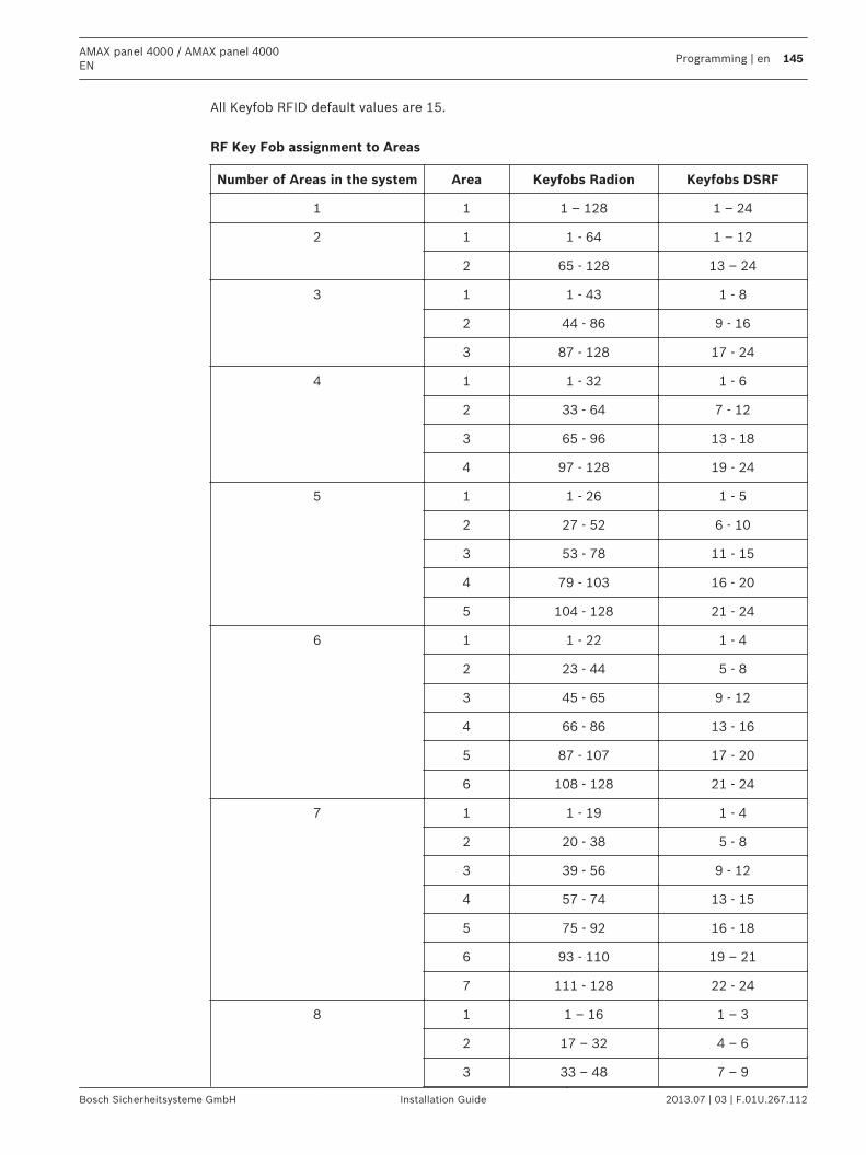
All Keyfob RFID default values are 15. RF Key Fob assignment to Areas
Number of Areas in the system Area Keyfobs Radion Keyfobs DSRF
1 1 1 – 128 1 – 24
2 1 1 - 64 1 – 12
2 65 - 128 13 – 24
3 1 1 - 43 1 - 8
2 44 - 86 9 - 16
3 87 - 128 17 - 24
4 1 1 - 32 1 - 6
2 33 - 64 7 - 12
3 65 - 96 13 - 18
4 97 - 128 19 - 24
5 1 1 - 26 1 - 5
2 27 - 52 6 - 10
3 53 - 78 11 - 15
4 79 - 103 16 - 20
5 104 - 128 21 - 24
6 1 1 - 22 1 - 4
2 23 - 44 5 - 8
3 45 - 65 9 - 12
4 66 - 86 13 - 16
5 87 - 107 17 - 20
6 108 - 128 21 - 24
7 1 1 - 19 1 - 4
2 20 - 38 5 - 8
3 39 - 56 9 - 12
4 57 - 74 13 - 15
5 75 - 92 16 - 18
6 93 - 110 19 – 21
7 111 - 128 22 - 24
8 1 1 – 16 1 – 3
2 17 – 32 4 – 6
3 33 – 48 7 – 9
AMAX panel 4000 / AMAX panel 4000EN
Programming | en 145
Bosch Sicherheitsysteme GmbH Installation Guide 2013.07 | 03 | F.01U.267.112
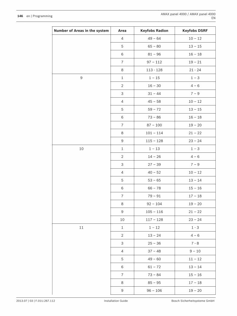
Number of Areas in the system Area Keyfobs Radion Keyfobs DSRF
4 49 – 64 10 – 12
5 65 – 80 13 – 15
6 81 – 96 16 – 18
7 97 – 112 19 – 21
8 113 - 128 21 - 24
9 1 1 – 15 1 – 3
2 16 – 30 4 – 6
3 31 – 44 7 – 9
4 45 – 58 10 – 12
5 59 – 72 13 – 15
6 73 – 86 16 – 18
7 87 – 100 19 – 20
8 101 – 114 21 – 22
9 115 – 128 23 – 24
10 1 1 – 13 1 – 3
2 14 – 26 4 – 6
3 27 – 39 7 – 9
4 40 – 52 10 – 12
5 53 – 65 13 – 14
6 66 – 78 15 – 16
7 79 – 91 17 – 18
8 92 – 104 19 – 20
9 105 – 116 21 – 22
10 117 – 128 23 – 24
11 1 1 – 12 1 - 3
2 13 – 24 4 – 6
3 25 – 36 7 - 8
4 37 – 48 9 – 10
5 49 – 60 11 – 12
6 61 – 72 13 – 14
7 73 – 84 15 – 16
8 85 – 95 17 – 18
9 96 – 106 19 – 20
146 en | ProgrammingAMAX panel 4000 / AMAX panel 4000
EN
2013.07 | 03 | F.01U.267.112 Installation Guide Bosch Sicherheitsysteme GmbH
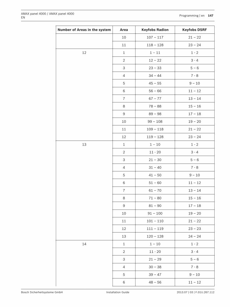
Number of Areas in the system Area Keyfobs Radion Keyfobs DSRF
10 107 – 117 21 – 22
11 118 – 128 23 – 24
12 1 1 – 11 1 - 2
2 12 – 22 3 - 4
3 23 – 33 5 – 6
4 34 – 44 7 - 8
5 45 – 55 9 – 10
6 56 – 66 11 – 12
7 67 – 77 13 – 14
8 78 – 88 15 – 16
9 89 – 98 17 – 18
10 99 – 108 19 – 20
11 109 – 118 21 – 22
12 119 – 128 23 – 24
13 1 1 – 10 1 - 2
2 11 - 20 3 - 4
3 21 – 30 5 – 6
4 31 – 40 7 - 8
5 41 – 50 9 – 10
6 51 – 60 11 – 12
7 61 – 70 13 – 14
8 71 – 80 15 – 16
9 81 – 90 17 – 18
10 91 – 100 19 – 20
11 101 – 110 21 – 22
12 111 – 119 23 – 23
13 120 – 128 24 – 24
14 1 1 – 10 1 - 2
2 11 - 20 3 - 4
3 21 – 29 5 – 6
4 30 – 38 7 - 8
5 39 – 47 9 – 10
6 48 – 56 11 – 12
AMAX panel 4000 / AMAX panel 4000EN
Programming | en 147
Bosch Sicherheitsysteme GmbH Installation Guide 2013.07 | 03 | F.01U.267.112
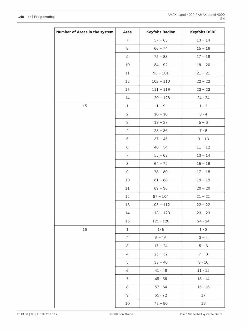
Number of Areas in the system Area Keyfobs Radion Keyfobs DSRF
7 57 – 65 13 – 14
8 66 – 74 15 – 16
9 75 – 83 17 – 18
10 84 – 92 19 – 20
11 93 – 101 21 – 21
12 102 – 110 22 – 22
13 111 – 119 23 – 23
14 120 – 128 24 - 24
15 1 1 – 9 1 - 2
2 10 – 18 3 - 4
3 19 – 27 5 – 6
4 28 – 36 7 - 8
5 37 – 45 9 – 10
6 46 – 54 11 – 12
7 55 – 63 13 – 14
8 64 – 72 15 – 16
9 73 – 80 17 – 18
10 81 – 88 19 – 19
11 89 – 96 20 – 20
12 97 – 104 21 – 21
13 105 – 112 22 – 22
14 113 – 120 23 – 23
15 121 - 128 24 - 24
16 1 1- 8 1 - 2
2 9 – 16 3 – 4
3 17 – 24 5 – 6
4 25 – 32 7 – 8
5 33 – 40 9 - 10
6 41 - 48 11 - 12
7 49 - 56 13 - 14
8 57 - 64 15 - 16
9 65 - 72 17
10 73 – 80 18
148 en | ProgrammingAMAX panel 4000 / AMAX panel 4000
EN
2013.07 | 03 | F.01U.267.112 Installation Guide Bosch Sicherheitsysteme GmbH
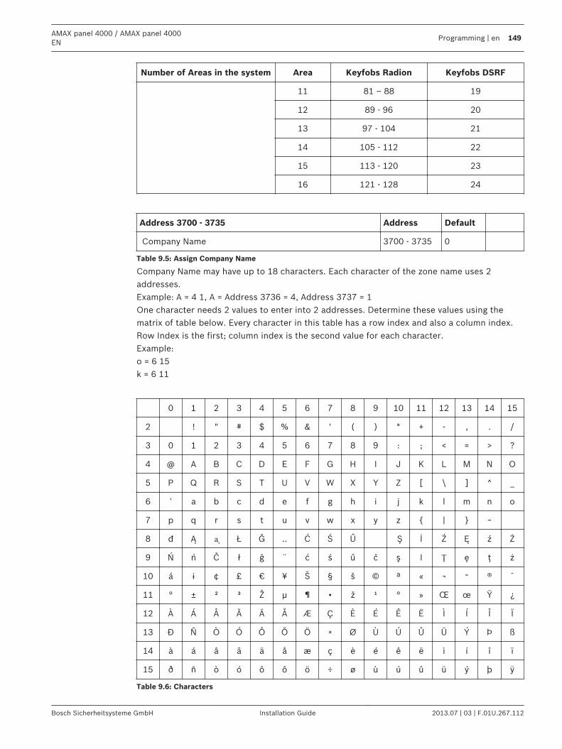
Number of Areas in the system Area Keyfobs Radion Keyfobs DSRF
11 81 – 88 19
12 89 - 96 20
13 97 - 104 21
14 105 - 112 22
15 113 - 120 23
16 121 - 128 24
Address 3700 - 3735 Address Default
Company Name 3700 - 3735 0
Table 9.5: Assign Company Name
Company Name may have up to 18 characters. Each character of the zone name uses 2addresses.Example: A = 4 1, A = Address 3736 = 4, Address 3737 = 1One character needs 2 values to enter into 2 addresses. Determine these values using thematrix of table below. Every character in this table has a row index and also a column index.Row Index is the first; column index is the second value for each character.Example:o = 6 15k = 6 11
0 1 2 3 4 5 6 7 8 9 10 11 12 13 14 15
2 ! " # $ % & ' ( ) * + - , . /
3 0 1 2 3 4 5 6 7 8 9 : ; < = > ?
4 @ A B C D E F G H I J K L M N O
5 P Q R S T U V W X Y Z [ \ ] ^ _
6 ‛ a b c d e f g h i j k l m n o
7 p q r s t u v w x y z | ~
8 đ Ą ᶏ Ł Ğ .. Ć Ś Ű Ş İ Ź Ę ź Ż
9 Ń ń Č ł ǧ ¨ ć ś ű č ş I Ț ę ţ ż
10 á ɨ ¢ £ € ¥ Š § š © ª « ¬ ־ ® ¯
11 ° ± ² ³ Ž µ ¶ • ž ¹ ° » Œ œ Ÿ ¿
12 À Á Â Ã Ä Å Æ Ç È É Ê Ë Ì Í Î Ï
13 Đ Ñ Ò Ó Ô Õ Ö × Ø Ù Ú Û Ü Ý Þ ß
14 à á â ã ä å æ ç è é ê ë ì í î ï
15 ð ñ ò ó ô ô ö ÷ ø ù ú û ü ý þ ÿ
Table 9.6: Characters
AMAX panel 4000 / AMAX panel 4000EN
Programming | en 149
Bosch Sicherheitsysteme GmbH Installation Guide 2013.07 | 03 | F.01U.267.112
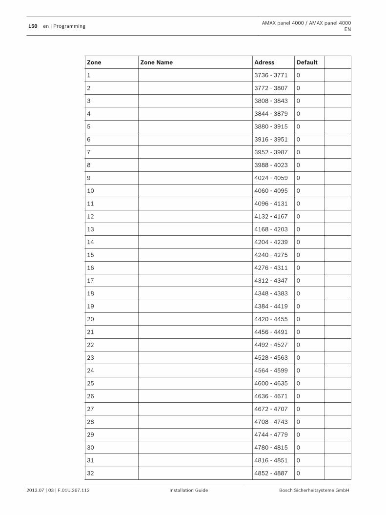
Zone Zone Name Adress Default
1 3736 - 3771 0
2 3772 - 3807 0
3 3808 - 3843 0
4 3844 - 3879 0
5 3880 - 3915 0
6 3916 - 3951 0
7 3952 - 3987 0
8 3988 - 4023 0
9 4024 - 4059 0
10 4060 - 4095 0
11 4096 - 4131 0
12 4132 - 4167 0
13 4168 - 4203 0
14 4204 - 4239 0
15 4240 - 4275 0
16 4276 - 4311 0
17 4312 - 4347 0
18 4348 - 4383 0
19 4384 - 4419 0
20 4420 - 4455 0
21 4456 - 4491 0
22 4492 - 4527 0
23 4528 - 4563 0
24 4564 - 4599 0
25 4600 - 4635 0
26 4636 - 4671 0
27 4672 - 4707 0
28 4708 - 4743 0
29 4744 - 4779 0
30 4780 - 4815 0
31 4816 - 4851 0
32 4852 - 4887 0
150 en | ProgrammingAMAX panel 4000 / AMAX panel 4000
EN
2013.07 | 03 | F.01U.267.112 Installation Guide Bosch Sicherheitsysteme GmbH
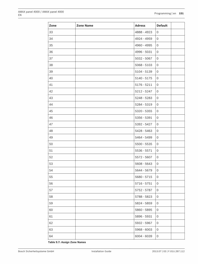
Zone Zone Name Adress Default
33 4888 - 4923 0
34 4924 - 4959 0
35 4960 - 4995 0
36 4996 - 5031 0
37 5032 - 5067 0
38 5068 - 5103 0
39 5104 - 5139 0
40 5140 - 5175 0
41 5176 - 5211 0
42 5212 - 5247 0
43 5248 - 5283 0
44 5284 - 5319 0
45 5320 - 5355 0
46 5356 - 5391 0
47 5392 - 5427 0
48 5428 - 5463 0
49 5464 - 5499 0
50 5500 - 5535 0
51 5536 - 5571 0
52 5572 - 5607 0
53 5608 - 5643 0
54 5644 - 5679 0
55 5680 - 5715 0
56 5716 - 5751 0
57 5752 - 5787 0
58 5788 - 5823 0
59 5824 - 5859 0
60 5860 - 5895 0
61 5896 - 5931 0
62 5932 - 5967 0
63 5968 - 6003 0
64 6004 - 6039 0
Table 9.7: Assign Zone Names
AMAX panel 4000 / AMAX panel 4000EN
Programming | en 151
Bosch Sicherheitsysteme GmbH Installation Guide 2013.07 | 03 | F.01U.267.112
Zone Name may have up to 18 characters. Each character of the zone name uses 2 addresses.Example: A = 4 1, A = Address 3736 = 4, Address 3737 = 1
152 en | ProgrammingAMAX panel 4000 / AMAX panel 4000
EN
2013.07 | 03 | F.01U.267.112 Installation Guide Bosch Sicherheitsysteme GmbH
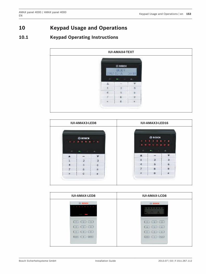
Keypad Usage and Operations
Keypad Operating Instructions
IUI-AMAX4-TEXT
IUI-AMAX3-LED8 IUI-AMAX3-LED16
IUI-AMAX-LED8 IUI-AMAX-LCD8
10
10.1
AMAX panel 4000 / AMAX panel 4000EN
Keypad Usage and Operations | en 153
Bosch Sicherheitsysteme GmbH Installation Guide 2013.07 | 03 | F.01U.267.112
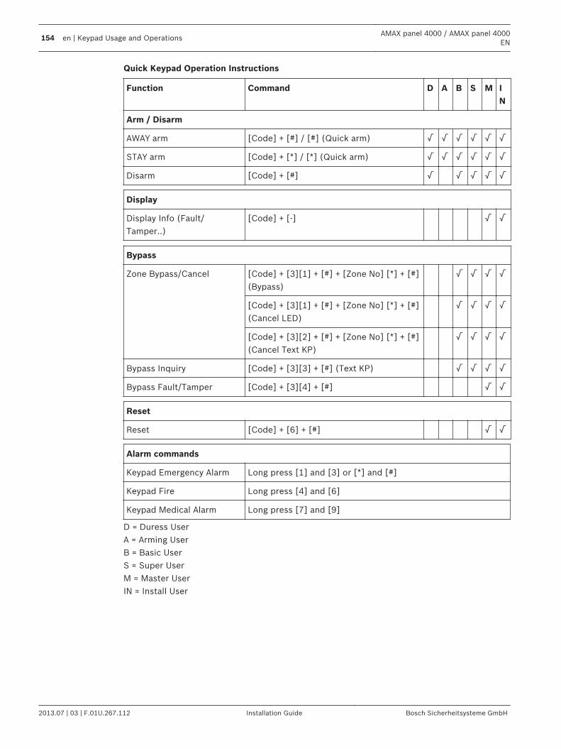
Quick Keypad Operation Instructions
Function Command D A B S M IN
Arm / Disarm
AWAY arm [Code] + [#] / [#] (Quick arm) √ √ √ √ √ √
STAY arm [Code] + [*] / [*] (Quick arm) √ √ √ √ √ √
Disarm [Code] + [#] √ √ √ √ √
Display
Display Info (Fault/Tamper..)
[Code] + [-] √ √
Bypass
Zone Bypass/Cancel [Code] + [3][1] + [#] + [Zone No] [*] + [#](Bypass)
√ √ √ √
[Code] + [3][1] + [#] + [Zone No] [*] + [#](Cancel LED)
√ √ √ √
[Code] + [3][2] + [#] + [Zone No] [*] + [#](Cancel Text KP)
√ √ √ √
Bypass Inquiry [Code] + [3][3] + [#] (Text KP) √ √ √ √
Bypass Fault/Tamper [Code] + [3][4] + [#] √ √
Reset
Reset [Code] + [6] + [#] √ √
Alarm commands
Keypad Emergency Alarm Long press [1] and [3] or [*] and [#]
Keypad Fire Long press [4] and [6]
Keypad Medical Alarm Long press [7] and [9]
D = Duress UserA = Arming UserB = Basic UserS = Super UserM = Master UserIN = Install User
154 en | Keypad Usage and OperationsAMAX panel 4000 / AMAX panel 4000
EN
2013.07 | 03 | F.01U.267.112 Installation Guide Bosch Sicherheitsysteme GmbH
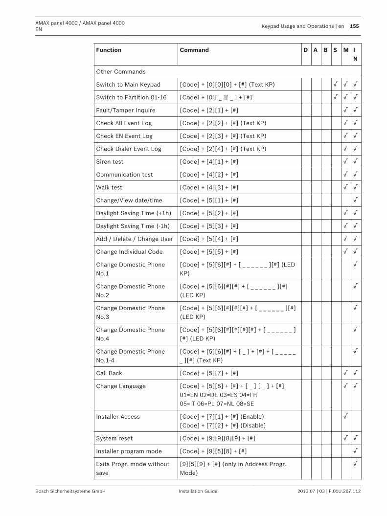
Function Command D A B S M IN
Other Commands
Switch to Main Keypad [Code] + [0][0][0] + [#] (Text KP) √ √ √
Switch to Partition 01-16 [Code] + [0][ _ ][ _ ] + [#] √ √ √
Fault/Tamper Inquire [Code] + [2][1] + [#] √ √
Check All Event Log [Code] + [2][2] + [#] (Text KP) √ √
Check EN Event Log [Code] + [2][3] + [#] (Text KP) √ √
Check Dialer Event Log [Code] + [2][4] + [#] (Text KP) √ √
Siren test [Code] + [4][1] + [#] √ √
Communication test [Code] + [4][2] + [#] √ √
Walk test [Code] + [4][3] + [#] √ √
Change/View date/time [Code] + [5][1] + [#] √
Daylight Saving Time (+1h) [Code] + [5][2] + [#] √ √
Daylight Saving Time (-1h) [Code] + [5][3] + [#] √ √
Add / Delete / Change User [Code] + [5][4] + [#] √ √
Change Individual Code [Code] + [5][5] + [#] √ √
Change Domestic PhoneNo.1
[Code] + [5][6][#] + [ _ _ _ _ _ _ ][#] (LEDKP)
√
Change Domestic PhoneNo.2
[Code] + [5][6][#][#] + [ _ _ _ _ _ _ ][#](LED KP)
√
Change Domestic PhoneNo.3
[Code] + [5][6][#][#][#] + [ _ _ _ _ _ _ ][#](LED KP)
√
Change Domestic PhoneNo.4
[Code] + [5][6][#][#][#][#] + [ _ _ _ _ _ _ ][#] (LED KP)
√
Change Domestic PhoneNo.1-4
[Code] + [5][6][#] + [ _ ] + [#] + [ _ _ _ _ __ ][#] (Text KP)
√
Call Back [Code] + [5][7] + [#] √ √
Change Language [Code] + [5][8] + [#] + [ _ ] [ _ ] + [#]01=EN 02=DE 03=ES 04=FR05=IT 06=PL 07=NL 08=SE
√ √
Installer Access [Code] + [7][1] + [#] (Enable)[Code] + [7][2] + [#] (Disable)
√
System reset [Code] + [9][9][8][9] + [#] √ √
Installer program mode [Code] + [9][5][8] + [#] √
Exits Progr. mode withoutsave
[9][5][9] + [#] (only in Address Progr.Mode)
√
AMAX panel 4000 / AMAX panel 4000EN
Keypad Usage and Operations | en 155
Bosch Sicherheitsysteme GmbH Installation Guide 2013.07 | 03 | F.01U.267.112
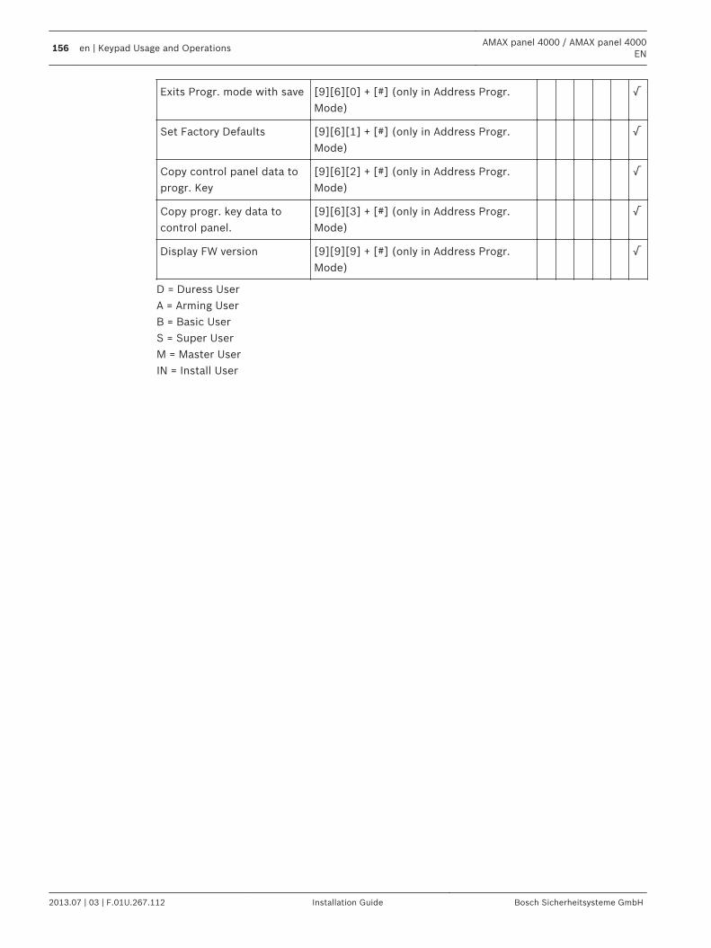
Exits Progr. mode with save [9][6][0] + [#] (only in Address Progr.Mode)
√
Set Factory Defaults [9][6][1] + [#] (only in Address Progr.Mode)
√
Copy control panel data toprogr. Key
[9][6][2] + [#] (only in Address Progr.Mode)
√
Copy progr. key data tocontrol panel.
[9][6][3] + [#] (only in Address Progr.Mode)
√
Display FW version [9][9][9] + [#] (only in Address Progr.Mode)
√
D = Duress UserA = Arming UserB = Basic UserS = Super UserM = Master UserIN = Install User
156 en | Keypad Usage and OperationsAMAX panel 4000 / AMAX panel 4000
EN
2013.07 | 03 | F.01U.267.112 Installation Guide Bosch Sicherheitsysteme GmbH
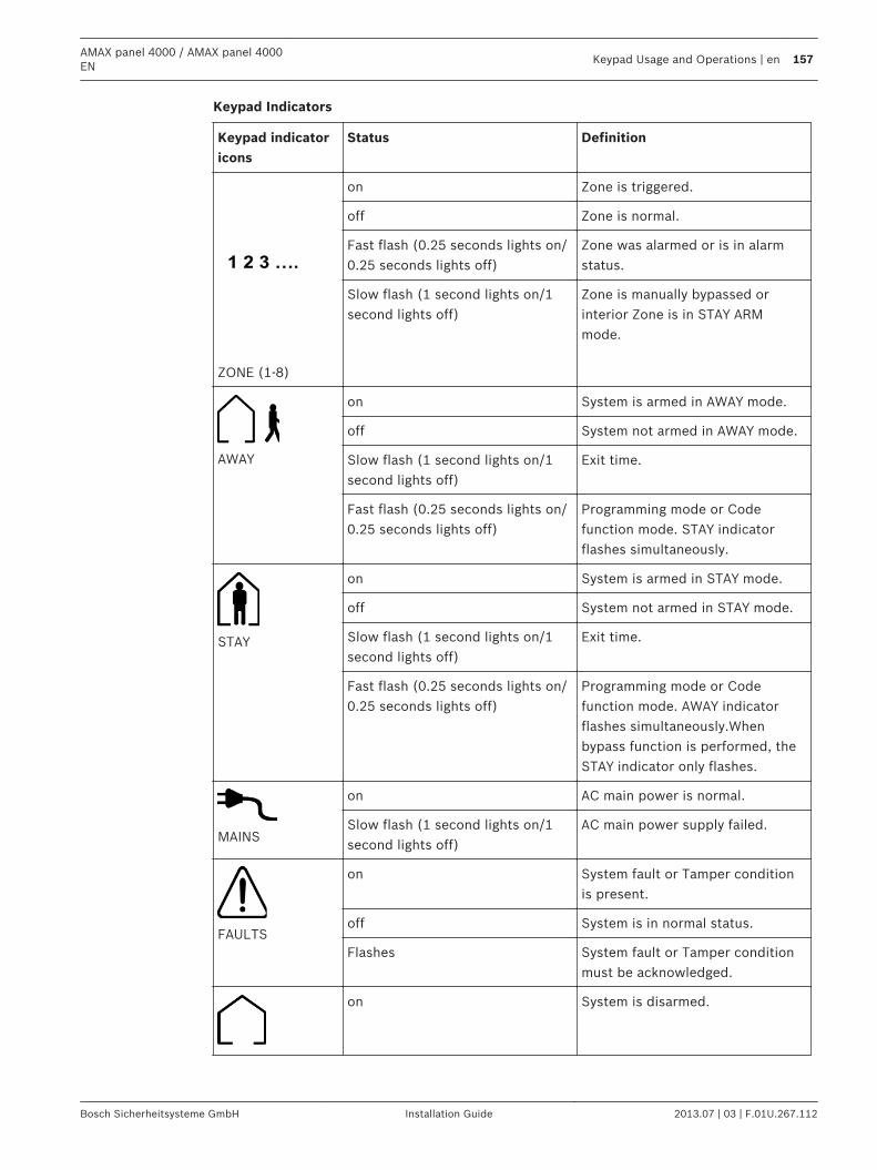
Keypad Indicators
Keypad indicatoricons
Status Definition
1 2 3 ….
ZONE (1-8)
on Zone is triggered.
off Zone is normal.
Fast flash (0.25 seconds lights on/0.25 seconds lights off)
Zone was alarmed or is in alarmstatus.
Slow flash (1 second lights on/1second lights off)
Zone is manually bypassed orinterior Zone is in STAY ARMmode.
AWAY
on System is armed in AWAY mode.
off System not armed in AWAY mode.
Slow flash (1 second lights on/1second lights off)
Exit time.
Fast flash (0.25 seconds lights on/0.25 seconds lights off)
Programming mode or Codefunction mode. STAY indicatorflashes simultaneously.
STAY
on System is armed in STAY mode.
off System not armed in STAY mode.
Slow flash (1 second lights on/1second lights off)
Exit time.
Fast flash (0.25 seconds lights on/0.25 seconds lights off)
Programming mode or Codefunction mode. AWAY indicatorflashes simultaneously.Whenbypass function is performed, theSTAY indicator only flashes.
MAINS
on AC main power is normal.
Slow flash (1 second lights on/1second lights off)
AC main power supply failed.
FAULTS
on System fault or Tamper conditionis present.
off System is in normal status.
Flashes System fault or Tamper conditionmust be acknowledged.
on System is disarmed.
AMAX panel 4000 / AMAX panel 4000EN
Keypad Usage and Operations | en 157
Bosch Sicherheitsysteme GmbH Installation Guide 2013.07 | 03 | F.01U.267.112
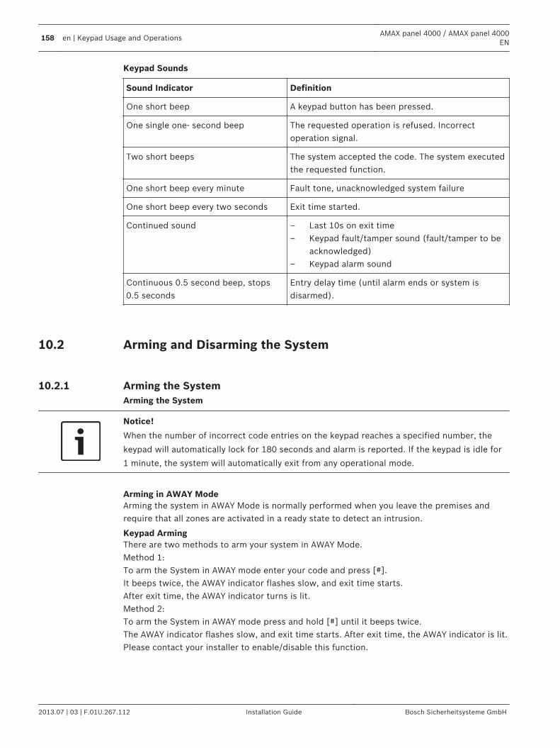
Keypad Sounds
Sound Indicator Definition
One short beep A keypad button has been pressed.
One single one- second beep The requested operation is refused. Incorrectoperation signal.
Two short beeps The system accepted the code. The system executedthe requested function.
One short beep every minute Fault tone, unacknowledged system failure
One short beep every two seconds Exit time started.
Continued sound – Last 10s on exit time– Keypad fault/tamper sound (fault/tamper to be
acknowledged)– Keypad alarm sound
Continuous 0.5 second beep, stops0.5 seconds
Entry delay time (until alarm ends or system isdisarmed).
Arming and Disarming the System
Arming the SystemArming the System
Notice!
When the number of incorrect code entries on the keypad reaches a specified number, the
keypad will automatically lock for 180 seconds and alarm is reported. If the keypad is idle for
1 minute, the system will automatically exit from any operational mode.
Arming in AWAY ModeArming the system in AWAY Mode is normally performed when you leave the premises andrequire that all zones are activated in a ready state to detect an intrusion.
Keypad ArmingThere are two methods to arm your system in AWAY Mode.Method 1:To arm the System in AWAY mode enter your code and press [#].It beeps twice, the AWAY indicator flashes slow, and exit time starts.After exit time, the AWAY indicator turns is lit.Method 2:To arm the System in AWAY mode press and hold [#] until it beeps twice.The AWAY indicator flashes slow, and exit time starts. After exit time, the AWAY indicator is lit.Please contact your installer to enable/disable this function.
10.2
10.2.1
158 en | Keypad Usage and OperationsAMAX panel 4000 / AMAX panel 4000
EN
2013.07 | 03 | F.01U.267.112 Installation Guide Bosch Sicherheitsysteme GmbH
Telephone Remote ArmingThe user dials the control panel number. The control panel answers the call and issues a longbeep. After the long beep, the user must press the [#] key. When the Panel receives the signalit will confirm the arming of the control panel with a high tone.Please contact your installer to enable/disable this function.
Notice!
Telephone arming is possible when the system has only 1 assigned area.
Key Switch ArmingUsers can use a key switch to Arm and Disarm the system. When the Key switch is activated,the AWAY indicator flashes slow and exit time starts. After exit time, the AWAY indicator is lit.When the Key switch is deactivated, the system is disarmed and Away indicator is off.
Disarming the SystemDisarming with CODEEnter your code and press [#] .It beeps twice and the AWAY or STAY indicator is extinguished.
Disarming with Key SwitchWhen the Key switch is deactivated, the system is disarmed and the AWAY or STAY indicator isextinguished.
Faults and Tamper ConditionsWhenever a system fault or tamper condition occurs, the FAULT or MAINS indicator flashesand the keypad beeps.
Notice!
Operation is only possible in disarmed status.
System Fault or Tamper Analysis Mode in LED KeypadTo enter fault or tamper analysis mode for determining a system fault or tamper condition:a) Enter your Code + [2] [1] and press [#]. It beeps twice. The FAULT indicator remains lit andthe STAY and AWAY indicators flash. The lit zone indicators indicate the type of fault or tampercondition that occurred.b) For a multi-level menu, enter the corresponding number to enter the submenu, press [ 0 ]key to return to the main menu (see table next page).c) To exit from Fault and Tamper Analysis Mode, press [#]. The STAY and AWAY indicators areextinguished and the FAULT indicator remains lit, and the keypad stops the beep.
10.2.2
10.3
10.3.1
AMAX panel 4000 / AMAX panel 4000EN
Keypad Usage and Operations | en 159
Bosch Sicherheitsysteme GmbH Installation Guide 2013.07 | 03 | F.01U.267.112
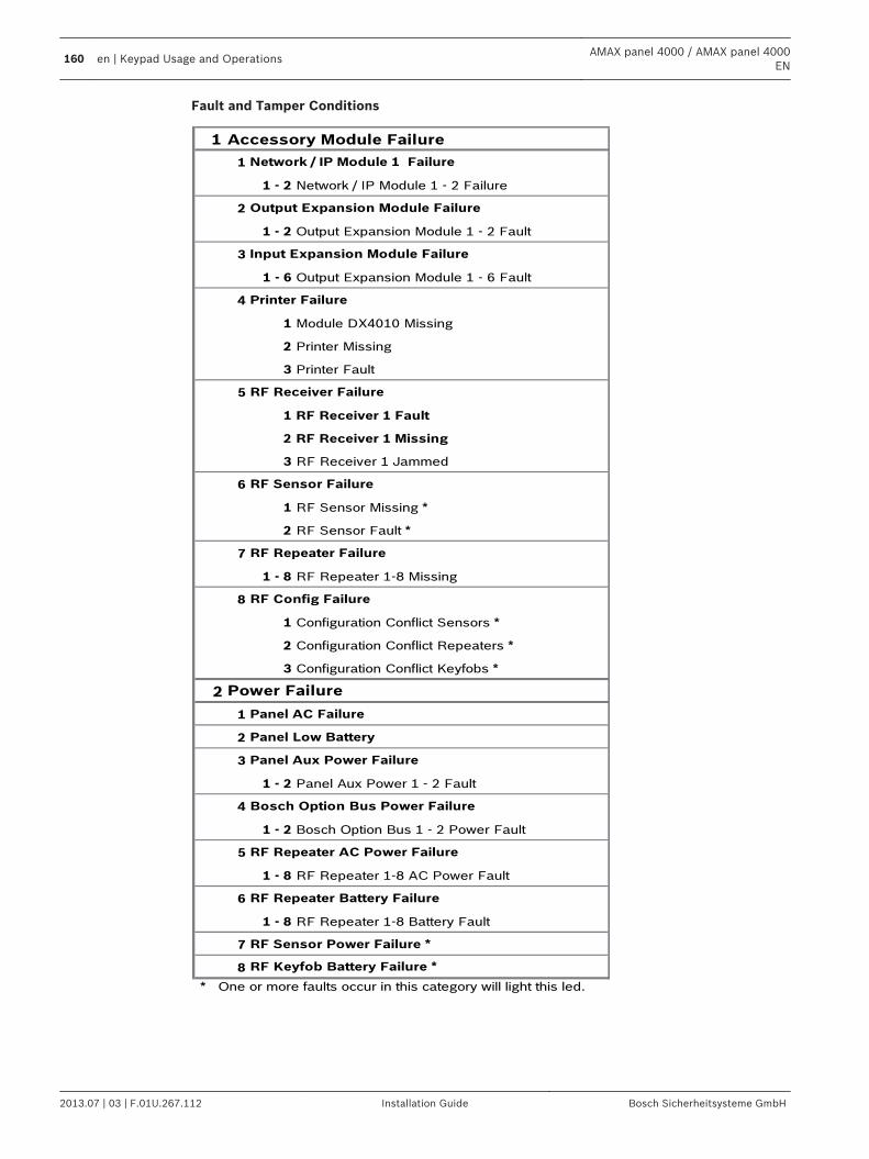
Fault and Tamper Conditions
1 Accessory Module Failure
1
1 - 2 Network / IP Module 1 - 2 Failure
2
1 - 2 Output Expansion Module 1 - 2 Fault
3
1 - 6 Output Expansion Module 1 - 6 Fault
4
1 Module DX4010 Missing
2 Printer Missing
3 Printer Fault
5
1 RF Receiver 1 Fault
2 RF Receiver 1 Missing
3 RF Receiver 1 Jammed
6
1 RF Sensor Missing *
2 RF Sensor Fault *
7
1 - 8 RF Repeater 1-8 Missing
8
1 Configuration Conflict Sensors *
2 Configuration Conflict Repeaters *
3 Configuration Conflict Keyfobs *
2
1
2
3
1 - 2 Panel Aux Power 1 - 2 Fault
4
1 - 2 Bosch Option Bus 1 - 2 Power Fault
5
1 - 8 RF Repeater 1-8 AC Power Fault
6
1 - 8 RF Repeater 1-8 Battery Fault
7
8
* One or more faults occur in this category will light this led.
Network / IP Module 1 Failure
Output Expansion Module Failure
RF Config Failure
RF Repeater Failure
RF Sensor Failure
RF Receiver Failure
Printer Failure
Input Expansion Module Failure
RF Repeater Battery Failure
RF Sensor Power Failure *
RF Keyfob Battery Failure *
Power Failure
Panel AC Failure
Panel Low Battery
Panel Aux Power Failure
Bosch Option Bus Power Failure
RF Repeater AC Power Failure
160 en | Keypad Usage and OperationsAMAX panel 4000 / AMAX panel 4000
EN
2013.07 | 03 | F.01U.267.112 Installation Guide Bosch Sicherheitsysteme GmbH
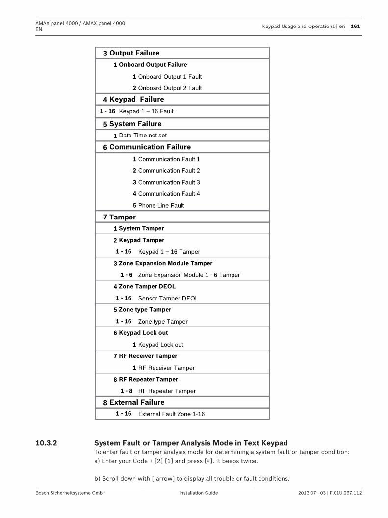
3
1
1 Onboard Output 1 Fault
2 Onboard Output 2 Fault
4
5
1
6
1 Communication Fault 1
2 Communication Fault 2
3 Communication Fault 3
4 Communication Fault 4
5 Phone Line Fault
7 Tamper
1
2
Keypad 1 – 16 Tamper
3
1 - 6 Zone Expansion Module 1 - 6 Tamper
4
Sensor Tamper DEOL
5
Zone type Tamper
6
1 Keypad Lock out
7
1 RF Receiver Tamper
8
1 - 8 RF Repeater Tamper
8
External Fault Zone 1-16
Keypad Failure
System Failure
Communication Failure
Onboard Output Failure
Keypad 1 – 16 Fault
Date Time not set
1 - 16
1 - 16
1 - 16
1 - 16
Output Failure
Keypad Tamper
System Tamper
1 - 16
External Failure
Zone Expansion Module Tamper
Zone Tamper DEOL
Zone type Tamper
Keypad Lock out
RF Receiver Tamper
RF Repeater Tamper
System Fault or Tamper Analysis Mode in Text Keypad To enter fault or tamper analysis mode for determining a system fault or tamper condition:a) Enter your Code + [2] [1] and press [#]. It beeps twice. b) Scroll down with [ arrow] to display all trouble or fault conditions.
10.3.2
AMAX panel 4000 / AMAX panel 4000EN
Keypad Usage and Operations | en 161
Bosch Sicherheitsysteme GmbH Installation Guide 2013.07 | 03 | F.01U.267.112
c) To exit from Fault and Tamper Analysis Mode, press [#].
System Test
Siren TestThis function allows the code holders to test the siren.a) Enter your Code + [4] [1] and press [#]. It beeps twice and the siren will be activated for 1second.
Communication TestThis function allows the code holders to send a test report to a central monitoring station.a) Enter your Code + [4] [2] and press [#]. It beeps twice and a test report is send.The Keypad will display the status of the test report for all communication paths.To exit the test report press [#].
Walk Test ModeThis function allows code holders to test detection devices to ensure they are functioningcorrectly. Before activating Walk test Mode, bypass any zones that are not required for testing.During the walk test, no walk test report is sent out to the control panel system.
How to enter into Walk Test Mode:1. Enter your Code + [4] [3] and press [#]. It beeps twice and the STAY and AWAY indicators
flash.2. Unseal and seal the zones to be tested. The keypad sounds one second beep and the
siren sounds one beep each time when a Zone status is changed.
To exit Walk test Mode:1. Enter your Code + [4] [3] and press [#].
Event Log Recall ModeThis function allows code holders to playback the last 254 events saved in each event log onthe Text Keypad.
All Event Log here all events are logged
EN Event Log here only EN related events are logged
Dialer Event Log here only Dialer related events are logged
How to enter Event Log Recall modes:All Event LogEnter your code + [2] [2] and press[#]. It beeps twice. EN Event LogEnter your code + [2] [3] and press [#]. It beeps twice.
10.4
10.4.1
10.4.2
10.4.3
10.5
162 en | Keypad Usage and OperationsAMAX panel 4000 / AMAX panel 4000
EN
2013.07 | 03 | F.01U.267.112 Installation Guide Bosch Sicherheitsysteme GmbH
Dialer Event LogEnter your code + [2] [4] and press [#]. It beeps twice. Press [] or [] to move up and down in the Event LogsPress [ #] To exit the Event Log
Reset the Control Panel This function allows code holders to reset all Alarms, Faults and Tamper conditions.Enter your code + [6][#].The keypad beeps twice and the signal is eliminated.
Notice!
You can reset alarms, faults or tamper conditions, only when they are not active anymore.
Bypassing
Bypassing ZonesBy bypassing Zones, one or more zones are disabled for one arming cycle. After bypassing azone, you can arm the system even when a zone is in alarm state.
How to Bypass a Zonea) Enter your code + [3] [1] and press [#]. The STAY indicator flashes fast.b) Enter the zone number you wish to bypass, then press the [*] key.(If you wish to bypass multiple zones, please repeat step b).c) Press [#] to exit.
How to Unbypass a ZoneLED Keypada) Enter your code + [3] [1] and press [#] . The STAY indicator flashes fast.b) Enter the zone number you wish to unbypass, then press the [*] key.(If you wish to unbypass multiple zones, please repeat step b).c) Press [#] to exit. Text Keypad:a) Enter your code + [3] [2] and press [#] . The STAY indicator flashes fast.b) Enter the zone number you wish to unbypass, then press the [*] key.(If you wish to unbypass multiple zones, please repeat step b)d) Press [#] to exit.
Bypassing Faults and Tamper conditions (Except Zone Tampers)One or more faults and tamper conditions are disabled for one arming cycle. After bypassing aFault or Tamper condition, you can arm the system even when a Fault or Tamper conditionexists. How to bypass a Fault or Tamper Condition
10.6
10.7
10.7.1
AMAX panel 4000 / AMAX panel 4000EN
Keypad Usage and Operations | en 163
Bosch Sicherheitsysteme GmbH Installation Guide 2013.07 | 03 | F.01U.267.112
a) Enter your code + [3] [4] and press [#]. It beeps twice. Bypass InquireThe bypass inquires displays all bypassed zones.a) Enter your code + [3] [3] and press [#]. It beeps twice.b) Move up and down with [] or [] to display all bypassed zones.c) Press [#] to exit.
Codes
Add/Change and Delete User CodeThis function allows Master User to Add/change and Delete User Codes.
How to Change the Code, User Code Priority and Area AssignmentLED Keypad:a) Enter your User code + [5] [4] and press [#].It beeps twice and the STAY and AWAY indicators start flashing. b) Enter the user number (1-64) and press [#].It beeps twice.The corresponding Keypad indicator will light up for the current user permission level.When AWAY and STAY indicators are flashing user permission level = 0. c) Enter the user code priority (0-5) and press [#], there are no beeps to confirm theoperation.00 = Master User01 = Super User02 = Basic User03 = Arming User04 = Duress User05-15 = No PermissionRefer to Quick Keypad Operation Instructions d) Enter the first value (00-71) for the area assignment for this user and press [#], there areno beeps to confirm the operation.The corresponding Keypad indicators will light up.Enter the second value for the area assignment, and press [#], there are no beeps to confirmthe operation.The corresponding Keypad indicators will light up.Please contact your installer for the right Values or check Table in Quick Reference Guide. e) Enter the new user code (Default code length=4 digits / 5 or 6 digit code must be enabledthrough the installer) for this user and press [#].It beeps twice and the STAY and AWAY indicators stop flashing. Text Keypad: a) Enter your code and press [5] [4] [#].It beeps twice and the STAY and AWAY indicators start flashing.
10.8
10.8.1
164 en | Keypad Usage and OperationsAMAX panel 4000 / AMAX panel 4000
EN
2013.07 | 03 | F.01U.267.112 Installation Guide Bosch Sicherheitsysteme GmbH
b) Enter the user number (1-64) and press [#]. c) Enter the user code priority (0-15) and press [#].00 = Master User01 = Super User02 = Basic User03 = Arming User04 = Duress User05-15 = No Permission d) Enter the value (00-71) for the area assignment for this user and press [#].Please contact your installer for the right Values or check Table in Quick Reference Guide. e) Enter the new user code (Default code length=4 digits / 5 or 6 digit code must be enabledthrough the installer) and press [#].It beeps twice and the Keypad shows the next user. f) Press long [-] to exit.
Notice!
This function is automatically terminated if you do not press a button within 240 seconds or if
you press [#]. One long beep indicates that the code already exists or that you entered an
incorrect user number.
Change Individual CodeThis function allows user to change the individual code.How to change the codea) Enter your code + [5] [5] [#] and press.It beeps twice and the STAY and AWAY indicators start flashing. b) Enter the new code (Default code length=4 digits / 5or 6 digit code must be enabledthrough the installer) and press [#].It beeps twice and the STAY and AWAY indicators stop flashing.
Keypad Alarm Operation Commands
Keypad Panic AlarmIf you simultaneously press and hold [1] and [3] or simultaneously press and hold [*] and [#]for 3 seconds a silent panic alarm will be transmitted.Please contact your installer to enable/disable the keypad emergency alarm functionality.
10.8.2
10.9
10.9.1
AMAX panel 4000 / AMAX panel 4000EN
Keypad Usage and Operations | en 165
Bosch Sicherheitsysteme GmbH Installation Guide 2013.07 | 03 | F.01U.267.112
Keypad Fire AlarmIf you simultaneously press and hold [4] and [6] for 3 seconds a silent keypad fire alarm willbe transmitted.Please contact your installer to enable/disable the fire alarm functionality.
Keypad Medical AlarmIf you simultaneously press and hold [7] and [9] for 3 seconds a silent keypad medical alarmwill be transmitted.Please contact your installer to enable/disable the emergency medical alarm functionality.
Domestic DialingDomestic Dialing AlarmWhen the control panel is activated into zone tamper/zone alarm, it can dial a mobile phone ortelephone number of a family member/friend. A maximum of four telephone numbers can becalled through the control panel during an alarm.Contact your installer to enable/disable the Domestic dialing functionality.
Confirming the Domestic callAll alarm events need acknowledgement.The transmission sequence is repeated until the control panel receives an acknowledgementtone.The control panel automatically hangs up after 45 seconds if it cannot detect theacknowledgement tone and redial later.The user presses [#] between two acknowledgement tones to confirm the alarm.If the control panel got the [#] acknowledgement from the user, it will send 2 second longbeep as acknowledge tone and hang up the line.
10.9.2
10.9.3
10.10
166 en | Keypad Usage and OperationsAMAX panel 4000 / AMAX panel 4000
EN
2013.07 | 03 | F.01U.267.112 Installation Guide Bosch Sicherheitsysteme GmbH
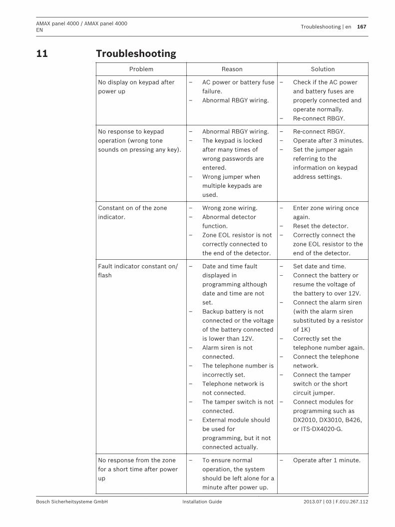
TroubleshootingProblem Reason Solution
No display on keypad afterpower up
– AC power or battery fusefailure.
– Abnormal RBGY wiring.
– Check if the AC powerand battery fuses areproperly connected andoperate normally.
– Re-connect RBGY.
No response to keypadoperation (wrong tonesounds on pressing any key).
– Abnormal RBGY wiring.– The keypad is locked
after many times ofwrong passwords areentered.
– Wrong jumper whenmultiple keypads areused.
– Re-connect RBGY.– Operate after 3 minutes.– Set the jumper again
referring to theinformation on keypadaddress settings.
Constant on of the zoneindicator.
– Wrong zone wiring.– Abnormal detector
function.– Zone EOL resistor is not
correctly connected tothe end of the detector.
– Enter zone wiring onceagain.
– Reset the detector.– Correctly connect the
zone EOL resistor to theend of the detector.
Fault indicator constant on/flash
– Date and time faultdisplayed inprogramming althoughdate and time are notset.
– Backup battery is notconnected or the voltageof the battery connectedis lower than 12V.
– Alarm siren is notconnected.
– The telephone number isincorrectly set.
– Telephone network isnot connected.
– The tamper switch is notconnected.
– External module shouldbe used forprogramming, but it notconnected actually.
– Set date and time.– Connect the battery or
resume the voltage ofthe battery to over 12V.
– Connect the alarm siren(with the alarm sirensubstituted by a resistorof 1K)
– Correctly set thetelephone number again.
– Connect the telephonenetwork.
– Connect the tamperswitch or the shortcircuit jumper.
– Connect modules forprogramming such asDX2010, DX3010, B426,or ITS-DX4020-G.
No response from the zonefor a short time after powerup
– To ensure normaloperation, the systemshould be left alone for aminute after power up.
– Operate after 1 minute.
11
AMAX panel 4000 / AMAX panel 4000EN
Troubleshooting | en 167
Bosch Sicherheitsysteme GmbH Installation Guide 2013.07 | 03 | F.01U.267.112
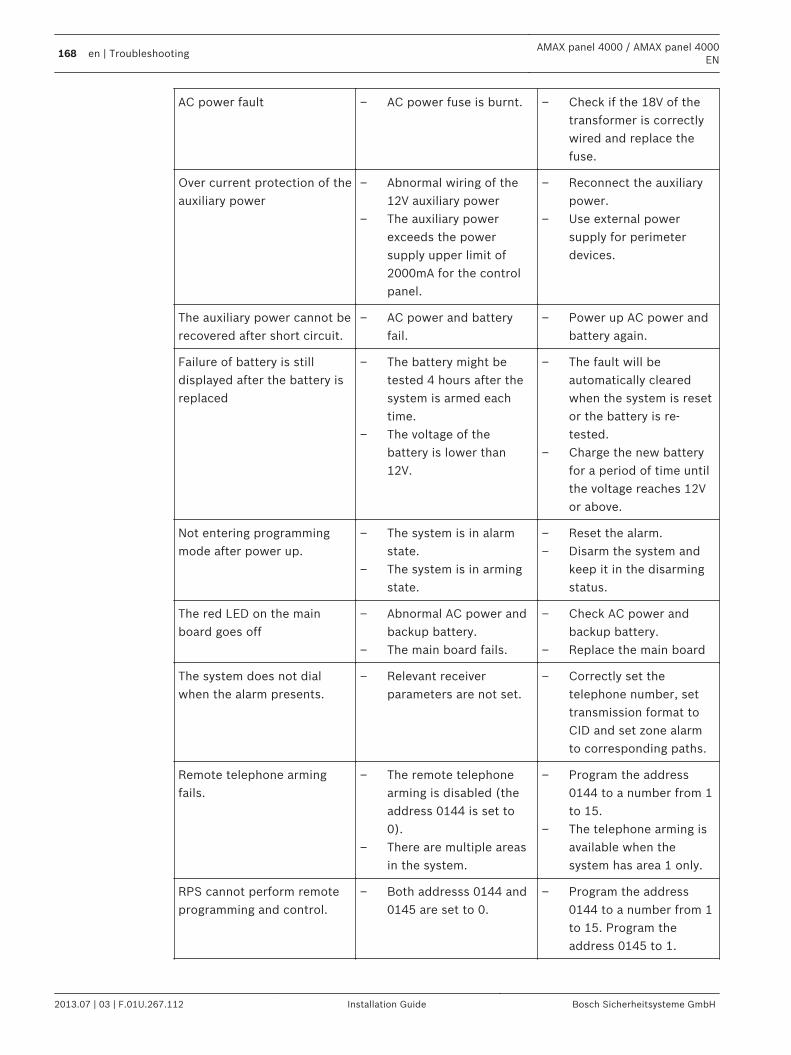
AC power fault – AC power fuse is burnt. – Check if the 18V of thetransformer is correctlywired and replace thefuse.
Over current protection of theauxiliary power
– Abnormal wiring of the12V auxiliary power
– The auxiliary powerexceeds the powersupply upper limit of2000mA for the controlpanel.
– Reconnect the auxiliarypower.
– Use external powersupply for perimeterdevices.
The auxiliary power cannot berecovered after short circuit.
– AC power and batteryfail.
– Power up AC power andbattery again.
Failure of battery is stilldisplayed after the battery isreplaced
– The battery might betested 4 hours after thesystem is armed eachtime.
– The voltage of thebattery is lower than12V.
– The fault will beautomatically clearedwhen the system is resetor the battery is re-tested.
– Charge the new batteryfor a period of time untilthe voltage reaches 12Vor above.
Not entering programmingmode after power up.
– The system is in alarmstate.
– The system is in armingstate.
– Reset the alarm.– Disarm the system and
keep it in the disarmingstatus.
The red LED on the mainboard goes off
– Abnormal AC power andbackup battery.
– The main board fails.
– Check AC power andbackup battery.
– Replace the main board
The system does not dialwhen the alarm presents.
– Relevant receiverparameters are not set.
– Correctly set thetelephone number, settransmission format toCID and set zone alarmto corresponding paths.
Remote telephone armingfails.
– The remote telephonearming is disabled (theaddress 0144 is set to0).
– There are multiple areasin the system.
– Program the address0144 to a number from 1to 15.
– The telephone arming isavailable when thesystem has area 1 only.
RPS cannot perform remoteprogramming and control.
– Both addresss 0144 and0145 are set to 0.
– Program the address0144 to a number from 1to 15. Program theaddress 0145 to 1.
168 en | TroubleshootingAMAX panel 4000 / AMAX panel 4000
EN
2013.07 | 03 | F.01U.267.112 Installation Guide Bosch Sicherheitsysteme GmbH
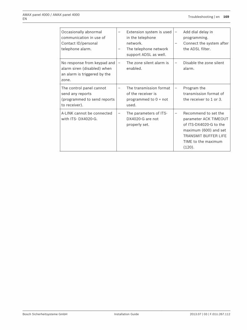
Occasionally abnormalcommunication in use ofContact ID/personaltelephone alarm.
– Extension system is usedin the telephonenetwork.
– The telephone networksupport ADSL as well.
– Add dial delay inprogramming.
– Connect the system afterthe ADSL filter.
No response from keypad andalarm siren (disabled) whenan alarm is triggered by thezone.
– The zone silent alarm isenabled.
– Disable the zone silentalarm.
The control panel cannotsend any reports(programmed to send reportsto receiver).
– The transmission formatof the receiver isprogrammed to 0 = notused.
– Program thetransmission format ofthe receiver to 1 or 3.
A-LINK cannot be connectedwith ITS- DX4020-G.
– The parameters of ITS-DX4020-G are notproperly set.
– Recommend to set theparameter ACK TIMEOUTof ITS-DX4020-G to themaximum (600) and setTRANSMIT BUFFER LIFETIME to the maximum(120).
AMAX panel 4000 / AMAX panel 4000EN
Troubleshooting | en 169
Bosch Sicherheitsysteme GmbH Installation Guide 2013.07 | 03 | F.01U.267.112
Maintenance12
170 en | MaintenanceAMAX panel 4000 / AMAX panel 4000
EN
2013.07 | 03 | F.01U.267.112 Installation Guide Bosch Sicherheitsysteme GmbH
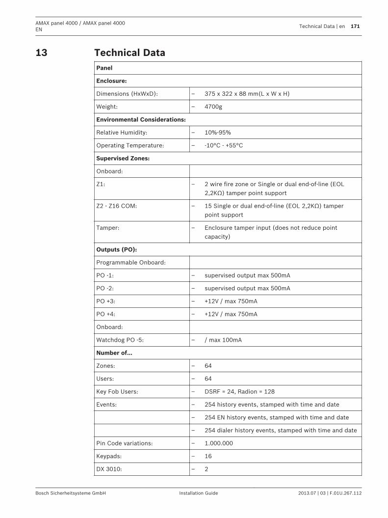
Technical DataPanel
Enclosure:
Dimensions (HxWxD): – 375 x 322 x 88 mm(L x W x H)
Weight: – 4700g
Environmental Considerations:
Relative Humidity: – 10%-95%
Operating Temperature: – -10°C - +55°C
Supervised Zones:
Onboard:
Z1: – 2 wire fire zone or Single or dual end-of-line (EOL2,2KΩ) tamper point support
Z2 - Z16 COM: – 15 Single or dual end-of-line (EOL 2,2KΩ) tamperpoint support
Tamper: – Enclosure tamper input (does not reduce pointcapacity)
Outputs (PO):
Programmable Onboard:
PO -1: – supervised output max 500mA
PO -2: – supervised output max 500mA
PO +3: – +12V / max 750mA
PO +4: – +12V / max 750mA
Onboard:
Watchdog PO -5: – / max 100mA
Number of...
Zones: – 64
Users: – 64
Key Fob Users: – DSRF = 24, Radion = 128
Events: – 254 history events, stamped with time and date
– 254 EN history events, stamped with time and date
– 254 dialer history events, stamped with time and date
Pin Code variations: – 1.000.000
Keypads: – 16
DX 3010: – 2
13
AMAX panel 4000 / AMAX panel 4000EN
Technical Data | en 171
Bosch Sicherheitsysteme GmbH Installation Guide 2013.07 | 03 | F.01U.267.112
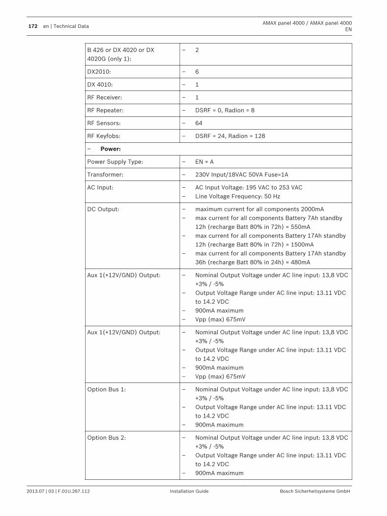
B 426 or DX 4020 or DX4020G (only 1):
– 2
DX2010: – 6
DX 4010: – 1
RF Receiver: – 1
RF Repeater: – DSRF = 0, Radion = 8
RF Sensors: – 64
RF Keyfobs: – DSRF = 24, Radion = 128
– Power:
Power Supply Type: – EN = A
Transformer: – 230V Input/18VAC 50VA Fuse=1A
AC Input: – AC Input Voltage: 195 VAC to 253 VAC– Line Voltage Frequency: 50 Hz
DC Output: – maximum current for all components 2000mA– max current for all components Battery 7Ah standby
12h (recharge Batt 80% in 72h) = 550mA– max current for all components Battery 17Ah standby
12h (recharge Batt 80% in 72h) = 1500mA– max current for all components Battery 17Ah standby
36h (recharge Batt 80% in 24h) = 480mA
Aux 1(+12V/GND) Output: – Nominal Output Voltage under AC line input: 13,8 VDC+3% / -5%
– Output Voltage Range under AC line input: 13.11 VDCto 14.2 VDC
– 900mA maximum– Vpp (max) 675mV
Aux 1(+12V/GND) Output: – Nominal Output Voltage under AC line input: 13,8 VDC+3% / -5%
– Output Voltage Range under AC line input: 13.11 VDCto 14.2 VDC
– 900mA maximum– Vpp (max) 675mV
Option Bus 1: – Nominal Output Voltage under AC line input: 13,8 VDC+3% / -5%
– Output Voltage Range under AC line input: 13.11 VDCto 14.2 VDC
– 900mA maximum
Option Bus 2: – Nominal Output Voltage under AC line input: 13,8 VDC+3% / -5%
– Output Voltage Range under AC line input: 13.11 VDCto 14.2 VDC
– 900mA maximum
172 en | Technical DataAMAX panel 4000 / AMAX panel 4000
EN
2013.07 | 03 | F.01U.267.112 Installation Guide Bosch Sicherheitsysteme GmbH
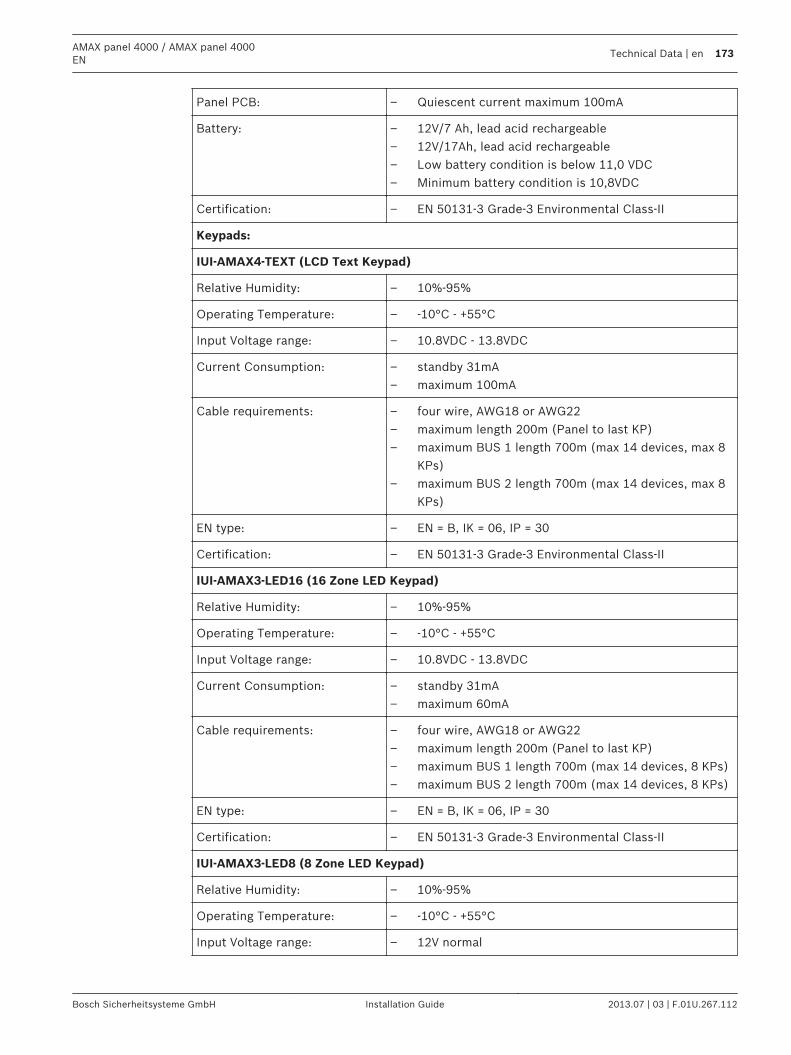
Panel PCB: – Quiescent current maximum 100mA
Battery: – 12V/7 Ah, lead acid rechargeable– 12V/17Ah, lead acid rechargeable– Low battery condition is below 11,0 VDC– Minimum battery condition is 10,8VDC
Certification: – EN 50131-3 Grade-3 Environmental Class-II
Keypads:
IUI-AMAX4-TEXT (LCD Text Keypad)
Relative Humidity: – 10%-95%
Operating Temperature: – -10°C - +55°C
Input Voltage range: – 10.8VDC - 13.8VDC
Current Consumption: – standby 31mA– maximum 100mA
Cable requirements: – four wire, AWG18 or AWG22– maximum length 200m (Panel to last KP)– maximum BUS 1 length 700m (max 14 devices, max 8
KPs)– maximum BUS 2 length 700m (max 14 devices, max 8
KPs)
EN type: – EN = B, IK = 06, IP = 30
Certification: – EN 50131-3 Grade-3 Environmental Class-II
IUI-AMAX3-LED16 (16 Zone LED Keypad)
Relative Humidity: – 10%-95%
Operating Temperature: – -10°C - +55°C
Input Voltage range: – 10.8VDC - 13.8VDC
Current Consumption: – standby 31mA– maximum 60mA
Cable requirements: – four wire, AWG18 or AWG22– maximum length 200m (Panel to last KP)– maximum BUS 1 length 700m (max 14 devices, 8 KPs)– maximum BUS 2 length 700m (max 14 devices, 8 KPs)
EN type: – EN = B, IK = 06, IP = 30
Certification: – EN 50131-3 Grade-3 Environmental Class-II
IUI-AMAX3-LED8 (8 Zone LED Keypad)
Relative Humidity: – 10%-95%
Operating Temperature: – -10°C - +55°C
Input Voltage range: – 12V normal
AMAX panel 4000 / AMAX panel 4000EN
Technical Data | en 173
Bosch Sicherheitsysteme GmbH Installation Guide 2013.07 | 03 | F.01U.267.112

Current Consumption: – standby 31mA– maximum 60mA
Cable requirements: – four wire, AWG18 or AWG22– maximum length 200m (Panel to last KP)– maximum BUS 1 length 700m (max 14 devices, 8 KPs)– maximum BUS 2 length 700m (max 14 devices, 8 KPs)
EN type: – EN = B, IK = 06, IP = 30
Certification: – EN 50131-3 Grade-3 Environmental Class-II
174 en | Technical DataAMAX panel 4000 / AMAX panel 4000
EN
2013.07 | 03 | F.01U.267.112 Installation Guide Bosch Sicherheitsysteme GmbH

Bosch Sicherheitssysteme GmbH
Robert-Bosch-Ring 5
85630 Grasbrunn
Germany
www.boschsecurity.com
© Bosch Sicherheitssysteme GmbH, 2013