ict-248311 d 6 - amarsi project
TRANSCRIPT

EU FP7
AMARSi
Adaptive Modular Architectures for Rich Motor Skills
ICT-248311
D 6.1
October 2011 (18 months)
Technical report on describingthe archetype architectures
Authors: Herbert Jaeger (Jacobs University Bremen), Jochen Steil(Bielefeld University) and Felix Reinhart (Bielefeld University)
Due date of deliverable 1st October 2011Actual submission date 5th November 2011Lead Partner Jacobs University BremenRevision FinalDissemination level Public
From Annex 1:
Develop at least one archetype architecture which solves the integration ofa large number of modules on a pre-cognitive level of reactive (but rich) be-havior (T.6.1)
M.6.1 Archetype architecture(s) available and relative strengths and weak-nesses assessed (M18, means of verification: deliverable 6.1)
Abstract
This report first surveys the architectures developed in the consortium andthen points out fundamental questions in architecture design. Based on thisdiscussion, a first sketch of a domain-specific language for rich motor skillarchitectures is introduced. Exemplary AMARSi architectures are rephrasedin terms of the proposed language. Finally, a novel type of module is outlinedwhich implements higher-level body coordination functionality.
Preface
The AMARSi consortium is committed to a collaborative effort for under-standing rich motor skills in humans and creating rich motor skills in robots.This ambitious goal needs combined efforts on several levels, which are dis-tributed among partners and workpackages and, consequently, tasks and de-liverables. At month 18, we reach an important intermediate stage, wherewe consider combinations of elementary skills from three points of view: inD6.1 we provide a conceptual approach to facilitate and operationalize fur-ther work on the architectures, in D7.2 we show experimental work withthe existing real robotic systems and in D7.3 we provide a technical pointof view which documents our efforts to create a commonly used softwarearchitecture. All these views complement and inform each other and conse-quently all discuss the example of trotting and reaching towards a ball fromtheir respective viewpoints. All three mentioned deliverables shall thereforebe evaluated in connection, because they provide a more complete picture ofthe progress in the consortium and, while self-contained text-wise, are deeplyconnected content-wise.
1

Contents
1 Overview of architecture related research in AMARSi up toM18 41.1 University of Gent . . . . . . . . . . . . . . . . . . . . . . . . 41.2 University of Bielefeld . . . . . . . . . . . . . . . . . . . . . . 51.3 SLF . . . . . . . . . . . . . . . . . . . . . . . . . . . . . . . . 61.4 EPFL . . . . . . . . . . . . . . . . . . . . . . . . . . . . . . . 71.5 Jacobs University . . . . . . . . . . . . . . . . . . . . . . . . . 111.6 Cognitive architectures in the iCub project . . . . . . . . . . . 141.7 Summary and discussion . . . . . . . . . . . . . . . . . . . . . 16
2 Fundamental questions arising in comprehensive architecturedesign: a survey 182.1 Scope of this survey . . . . . . . . . . . . . . . . . . . . . . . . 182.2 A continental divide: homogeneous vs. heterogeneous archi-
tectures; and its subdivides . . . . . . . . . . . . . . . . . . . . 202.3 A note on terminology . . . . . . . . . . . . . . . . . . . . . . 242.4 A catalog of theoretical issues . . . . . . . . . . . . . . . . . . 25
2.4.1 Synergies vs. individual actuators . . . . . . . . . . . . 252.4.2 Segmentation of motor behavior, identification of ”prim-
itives” . . . . . . . . . . . . . . . . . . . . . . . . . . . 262.4.3 Pattern generation plus tracking vs. integrated generation-
control . . . . . . . . . . . . . . . . . . . . . . . . . . . 262.4.4 Coupling ”CPGs” . . . . . . . . . . . . . . . . . . . . . 272.4.5 Stability on a whole system level . . . . . . . . . . . . 272.4.6 Fast adaptation of ”CPGs” . . . . . . . . . . . . . . . 272.4.7 Slow adaptation of ”CPGs” . . . . . . . . . . . . . . . 282.4.8 Differentiating between, and integrating of, proprio-
vs. external sensor processing mechanisms . . . . . . . 282.4.9 If behaviors have purposes or goals or cost functions –
where do they come from? . . . . . . . . . . . . . . . . 292.4.10 What is the nature of top-down pathways? . . . . . . . 312.4.11 How do we modularize? . . . . . . . . . . . . . . . . . 312.4.12 . . . and more . . . . . . . . . . . . . . . . . . . . . . . . 32
2.5 Lessons for an AMARSi architecture . . . . . . . . . . . . . . 33
3 A domain-specific terminology for AMARSi architectures 353.1 What is – and is not – in the scope of the AMARSi domain ? 363.2 AMARSi Control Spaces (ACS) . . . . . . . . . . . . . . . . . 37
3.2.1 What constitutes a control space? . . . . . . . . . . . . 37
2

3.2.2 What control spaces are offered or gained by the re-striction to the domain of AMARSi motor-skills? . . . 38
3.2.3 What are additional properties of an ACS? . . . . . . . 383.2.4 What kind of transformations between spaces are needed? 39
3.3 The AMARSi Dynamical Systems approach . . . . . . . . . . 403.3.1 How is the AMARSi commitment for dynamical sys-
tems implementations reflected? . . . . . . . . . . . . . 403.3.2 What is an adaptive module? . . . . . . . . . . . . . . 41
3.4 Modularization by Adaptive Components . . . . . . . . . . . . 433.4.1 Which level of modularization do we propose? . . . . . 433.4.2 Which types of components do we foresee? . . . . . . . 44
3.5 The Architecture Level . . . . . . . . . . . . . . . . . . . . . . 453.5.1 How to realize learning on the architectural level? . . . 453.5.2 How can dynamic extension of the architecture work? . 463.5.3 How to specify a particular instantiation of the con-
ceptual architecture? . . . . . . . . . . . . . . . . . . . 463.6 Discussion . . . . . . . . . . . . . . . . . . . . . . . . . . . . . 47
3.6.1 What is the no-free-lunch problem here? . . . . . . . . 473.6.2 What are the open issues? . . . . . . . . . . . . . . . . 483.6.3 Is there THE AMARSi Architecture or
Where do the semantics come from? . . . . . . . . . . 48
4 Example architectures 494.1 Exemplary conceptual architecture for the combination of skills 494.2 EPFL B architecture . . . . . . . . . . . . . . . . . . . . . . . 504.3 Body coordination architecture . . . . . . . . . . . . . . . . . 51
5 Conclusion 56
3

1 Overview of architecture related research
in AMARSi up to M18
We start by giving a survey of existing contributions to architectures withinthe AMARSi project. Where these have been documented in earlier deliver-ables, the treatment will be very concise. We also point out relevant workthat has been achieved by partners earlier or independently from AMARSi.After the survey a discussion of these contributions in the light of archetypearchitectures is given.
1.1 University of Gent
UGent has designed a number of elementary pattern generation and controlmodules based on reservoir computing:
• Neural central pattern generator (NCPG): training a reservoir as peri-odic pattern generator, possibly switching between patterns accordingto switching input. Documented in delivery D4.1, Section 9.
• Neural motor primitive control (NMPC): online adaptive version of aclassical echo state network control architecture for tracking controlwith observation feedback, using two weight-sharing reservoirs. Docu-mented in delivery D4.1, Section 5.
• Neural dynamical motion primitives generator (NDMPG): training areservoir to generate start-to-end transient trajectories, optionally withpost-processing simulating repellor-field obstacle avoidance. Documentedin delivery D4.1, Section 4.
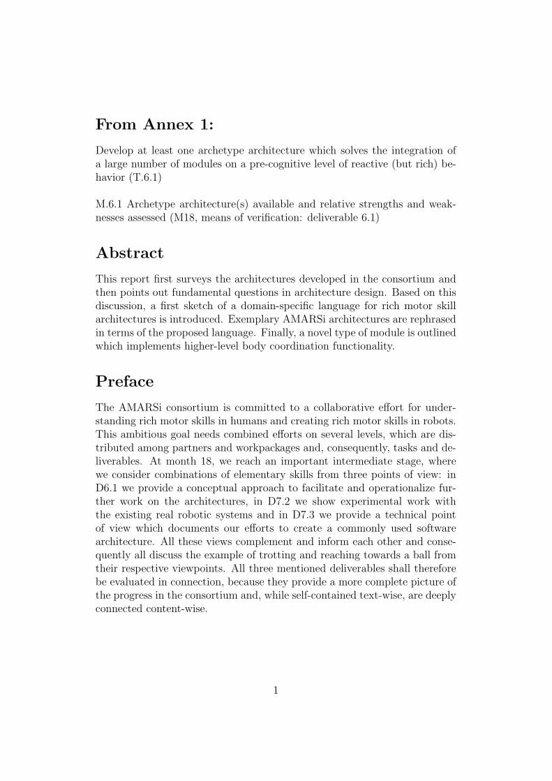
The NCPG and NDMPG can be considered as reservoir-based, trainable-from-data versions of the pattern generators developed in EPFL based onanalytic ordinary differential equation (ODE) models. Furthermore, UGenthas begun to design a layout for a complete control architecture (see Fig-ure 1), including higher cognitive levels. While this is early work, it pointsin a direction where in a layered architecture the various control layers havefunctionalities that are quite distinct from each other and would require dif-ferent methods for design and implementations each. This is of interest be-cause there are two schools of thought about global design principles, whereone view is to try to have as homogeneously designed control layers as possi-ble, whereas the other view immediately admits heterogeneity. More aboutthis in subsequent discussion sections.
4
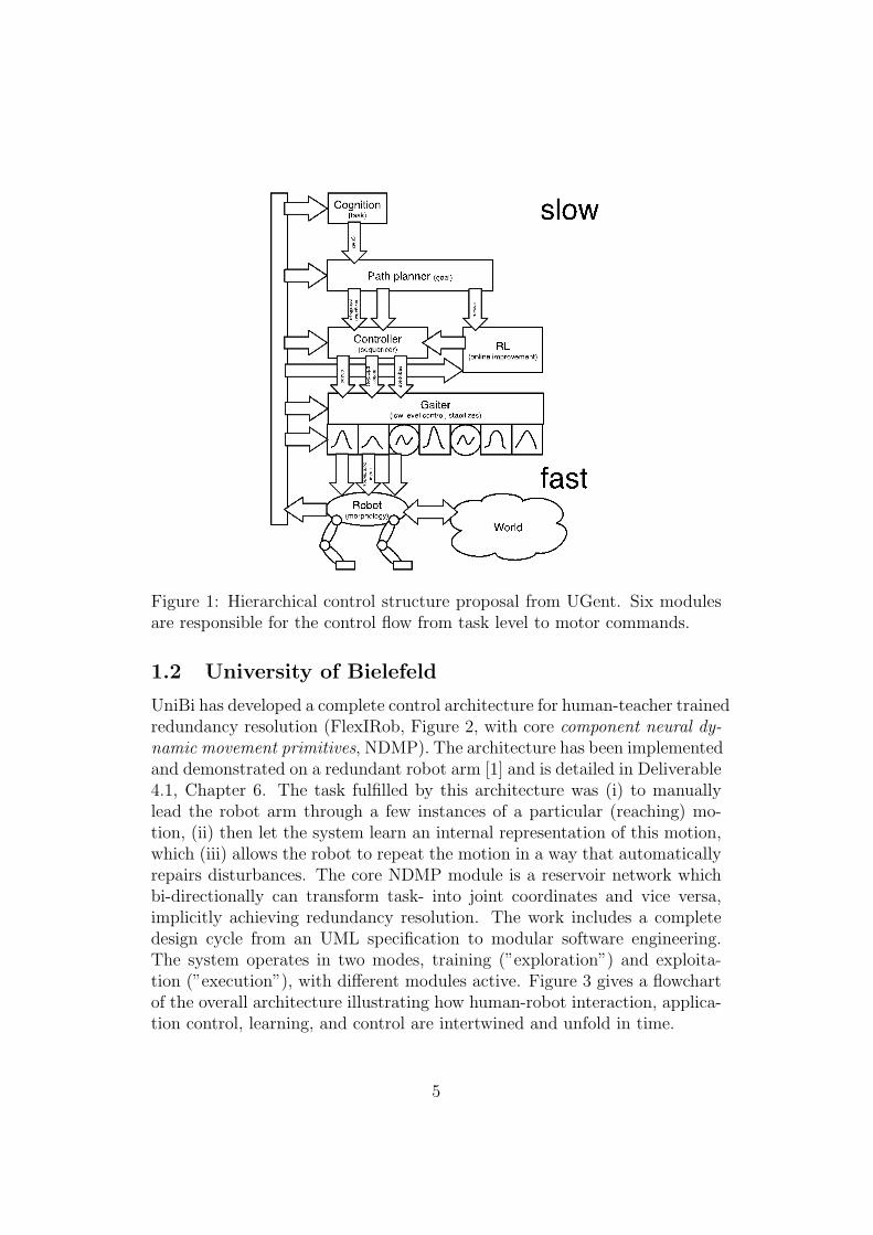
Figure 1: Hierarchical control structure proposal from UGent. Six modulesare responsible for the control flow from task level to motor commands.
1.2 University of Bielefeld
UniBi has developed a complete control architecture for human-teacher trainedredundancy resolution (FlexIRob, Figure 2, with core component neural dy-namic movement primitives, NDMP). The architecture has been implementedand demonstrated on a redundant robot arm [1] and is detailed in Deliverable4.1, Chapter 6. The task fulfilled by this architecture was (i) to manuallylead the robot arm through a few instances of a particular (reaching) mo-tion, (ii) then let the system learn an internal representation of this motion,which (iii) allows the robot to repeat the motion in a way that automaticallyrepairs disturbances. The core NDMP module is a reservoir network whichbi-directionally can transform task- into joint coordinates and vice versa,implicitly achieving redundancy resolution. The work includes a completedesign cycle from an UML specification to modular software engineering.The system operates in two modes, training (”exploration”) and exploita-tion (”execution”), with different modules active. Figure 3 gives a flowchartof the overall architecture illustrating how human-robot interaction, applica-tion control, learning, and control are intertwined and unfold in time.
5

Figure 2: Main blocks of the FlexIRob architecture (from [1]).
Figure 3: Exploration and execution activities in the FlexIRob system(from [1]).
1.3 SLF
While SLF is not directly concerned with robot architectures, it contributesan important idea with a bearing on architecture design, namely definitionsand organization principles of muscle synergies [2, 3]. A muscle synergy isa coordinated activation of many muscles involved in a particular class of
6
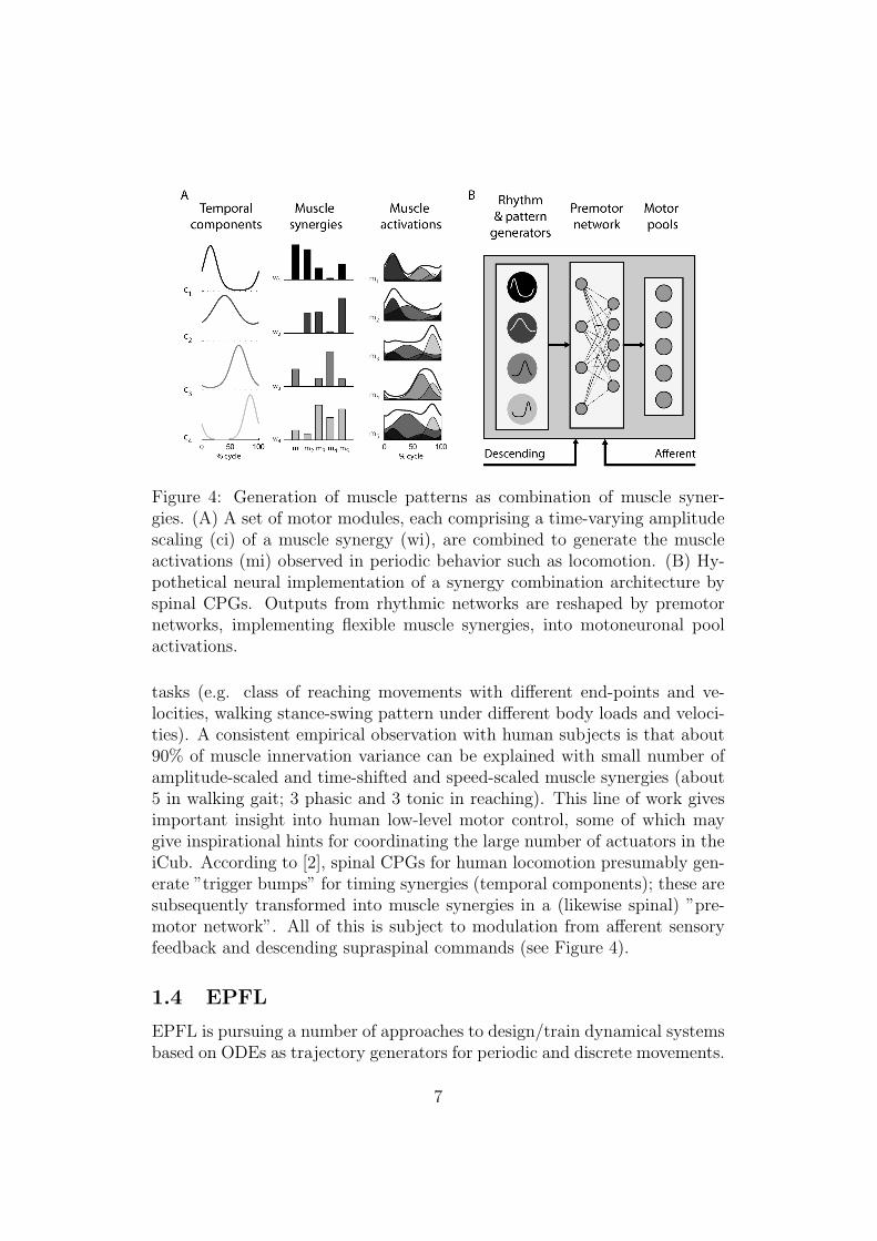
Figure 4: Generation of muscle patterns as combination of muscle syner-gies. (A) A set of motor modules, each comprising a time-varying amplitudescaling (ci) of a muscle synergy (wi), are combined to generate the muscleactivations (mi) observed in periodic behavior such as locomotion. (B) Hy-pothetical neural implementation of a synergy combination architecture byspinal CPGs. Outputs from rhythmic networks are reshaped by premotornetworks, implementing flexible muscle synergies, into motoneuronal poolactivations.
tasks (e.g. class of reaching movements with different end-points and ve-locities, walking stance-swing pattern under different body loads and veloci-ties). A consistent empirical observation with human subjects is that about90% of muscle innervation variance can be explained with small number ofamplitude-scaled and time-shifted and speed-scaled muscle synergies (about5 in walking gait; 3 phasic and 3 tonic in reaching). This line of work givesimportant insight into human low-level motor control, some of which maygive inspirational hints for coordinating the large number of actuators in theiCub. According to [2], spinal CPGs for human locomotion presumably gen-erate ”trigger bumps” for timing synergies (temporal components); these aresubsequently transformed into muscle synergies in a (likewise spinal) ”pre-motor network”. All of this is subject to modulation from afferent sensoryfeedback and descending supraspinal commands (see Figure 4).
1.4 EPFL
EPFL is pursuing a number of approaches to design/train dynamical systemsbased on ODEs as trajectory generators for periodic and discrete movements.
7

A research emphasis is on provable stability properties. These pattern gen-erators are demonstrated on robot arms and the iCub. This research has along tradition in EPFL and has led to a number of variants of how to designsuch central pattern generator (CPG) subsystems. The most salient ones arehere briefly pointed out:A. (group of A. Ijspeert) Modulated (non-periodic) dynamical movementprimitives (DMPs [4], detailed in Chapter 2 of Deliverable 4.1). Brief char-acterization:
• DMPs are a method to create ODE models for target trajectory genera-tion for multiple DOF robots. One obtains periodic attractor equationswhich are modulatable through control parameters in timing, ampli-tude, and shifts.
• Core idea: (i) start from a simple and fully analyzed point attractorsystem, here a damped spring-mass system, (ii) add forcing terms toits equation which can modulate the original relaxation dynamics inperiodic or non-periodic ways, (iii) make the forcing terms depend noton time but an auxiliary canonical system variable x whose dynamicsconverges to zero (ensuring asymptotic vanishing of forcing, hence sta-bility of overall system), (iv) make forcing terms learnable by standardfunction approximation methods.
• Architecture: for complex robots (drumming, tennis swings), the ba-sic idea has to be augmented to account for several limbs, obstacleavoidance, and others. This is done by
– having control subsystems consisting of a single canonical systemeach, whose temporal drive pattern is individually transformedinto position/velocity/acceleration for a number of DOFs
– coupling several such (limb-controlling) subsystems through cou-pling terms in the canonical systems (for temporal coordinationbetween limbs) and/or in the transformation systems (for spatialshaping by coupling with sensor feedback)
• DMPs have been successfully employed to endow a humanoid robotwith human-teachable controllers for periodic motions (drumming) andnon- periodic motions (tennis swing).
B. (group of A. Ijspeert) Combining periodic and non-periodic (”discrete”)motor primitives [5], detailed in Chapter 8 of Deliverable 4.1:
8

Figure 5: Architecture layout for iCub drumming (from [5]).
• Core idea: design motor primitives as linear superposition of a pointrelaxation system and a Hopf oscillator. By a small number of controlparameters such systems can be made to ”morph” between generatingpoint reaching and/or oscillatory target trajectories, both modulatable.Over time, such a system can generate smoothly blended periods ofreaching vs. oscillatory trajectories.
• A note on terminology: these motor primitives are also often called”CPG” by their investigators.
• The Hopf subsystem can be ”halted” by driving it into bifurcation.Thereafter it behaves as point attractor. This is used for active com-pliance (discontinue movement when hitting obstacle)
• These CPGs have been embedded in a complete control architecture(see Figure 5) for making the iCub play drums, where the drummingpattern is online user adaptive through a GUI. Each arm and leg andthe head is controlled by separate CPGs. The various CPGs are coor-dinated in time by a shared driver clock. Similarly this has been usedfor iCub crawling, only here the coordination between CPGs is doneby cross-coupling.
C. (group of Aude Billard): Approach C complements approaches followedin A and B and investigates an alternative dynamical systems modeling, in
9

Figure 6: Embedding the SEDS learning module in a basic control architec-ture (taken from [5]).
which one assumes that motions are driven by an autonomous dynamicalsystem. In other words, motions are here assumed to follow an ODE thatis time-invariant. Time-invariance is advantageous in that it no longer re-quires heuristics for time-rescaling when the motion is perturbed. However,time-invariance in non-linear dynamical systems induces issues of stabilitythat time-dependent techniques avoid. Methods are developed for learningan autonomous DS that are asymptotically stable at an attractor. These areapplied to control point-reaching movements. Learning proceeds from a fewdemonstration trajectories, by approximating the (assumed ground truth)ODE via mixtures of Gaussians [6, 7, 8], under strict constraints to ensurestability, as detailed in Chapter 3 of Deliverable 4.1. The autonomous DS isembedded into the architecture shown in Figure 6 which provides the infras-tructure for learning (supply of training data) and robot control (kinematictransformations and proprioceptive feedback). The architectures displayedin Figure 2 and Figure 6 share a common layering of control levels and bothinclude a kinesthetic, human-robot interaction phase.Two different learning methods have been employed and analyzed:
• Learning the model parameters (means and covariance matrices of par-ticipating Gaussians) by a constrained nonlinear optimization methodtermed SEDS (stable estimator of dynamical systems) leads to a modelwith analytically assured global stability (a unique fixed point attractorat the reaching target location) [7]
• Learning the model parameters via EM, achieving stability in a sub-
10
region of the total configuration space by an iterated test-refine strat-egy [6]
A combination of the above methods with obstacle avoidance was recentlydeveloped [8].Main properties of these models are:
• the time-invariant ODE nature of the model directly leads to robustcoping with spatial and temporal disruptions at execution time;
• the methods enjoy assured stability properties;
• the computational (learning) complexity are similar as or better thanother approaches in the field.
1.5 Jacobs University
At JAC there are two trains of thought related to architecture. The first,which one might dub ”complete behavior control architectures”, is concernedwith design principles for comprehensive architectures which cover the en-tire ”cognitive span” between low-level motor control and high-level actionselection and world representation. The second, which one might call ”mod-ulatable modules”, is concerned with principles of how a complex adaptivemodule, which is realized as a recurrent neural network (RNN), can be trainedto become modulatable (i.e. parametrized in a principled way) from higherlevels. Here both lines of research are briefly sketched out.Complete architectures. This topic has been investigated by H. Jaeger sinceabout 15 years. The earliest instance is the Dual Dynamics [9] architectureblueprint for behavior-based robots. Originally conceived in the mid 90’ies, ithas been implemented on a variety of robots in several groups in the contextof RoboCup (mid-size and small-size league), and is still being used at someplaces in updated formats. Its practical usefulness was witnessed by several1rst, 2nd, or 3rd placements in World and European RoboCup championshipsby Raul Roja’s group from the TU Berlin [10], and the RoboCup team fromthe Fraunhofer Institute AIS. The main characteristics of the Dual Dynamicsdesigns are the following (compare with Figure 7):
• The main (and single) building block is a behavior. Behaviors are ar-ranged in layers. Only behaviors on the lowest level have access to theactuators. Higher-level behaviors ”use” lower-level behaviors in thespirit of ”virtual complex actuators” and control them through select-ing and activating them in a graded fashion.
11
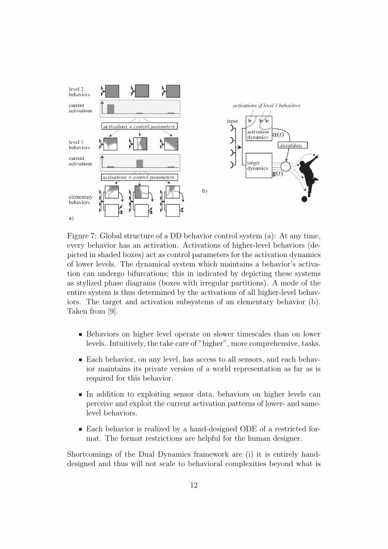
Figure 7: Global structure of a DD behavior control system (a): At any time,every behavior has an activation. Activations of higher-level behaviors (de-picted in shaded boxes) act as control parameters for the activation dynamicsof lower levels. The dynamical system which maintains a behavior’s activa-tion can undergo bifurcations; this in indicated by depicting these systemsas stylized phase diagrams (boxes with irregular partitions). A mode of theentire system is thus determined by the activations of all higher-level behav-iors. The target and activation subsystems of an elementary behavior (b).Taken from [9].
• Behaviors on higher level operate on slower timescales than on lowerlevels. Intuitively, the take care of ”higher”, more comprehensive, tasks.
• Each behavior, on any level, has access to all sensors, and each behav-ior maintains its private version of a world representation as far as isrequired for this behavior.
• In addition to exploiting sensor data, behaviors on higher levels canperceive and exploit the current activation patterns of lower- and same-level behaviors.
• Each behavior is realized by a hand-designed ODE of a restricted for-mat. The format restrictions are helpful for the human designer.
Shortcomings of the Dual Dynamics framework are (i) it is entirely hand-designed and thus will not scale to behavioral complexities beyond what is
12
needed for elementary soccer playing, (ii) there are no provisions for learning,(iii) again due to the reliance on design by hand, it is hard if not impossible toextend the framework to robot platforms of the complexity of, say, an iCub.After about 2002, Jaeger and his group turned away from robotic applica-tions and investigated hierarchical neural architectures for dynamic patternrecognition (e.g. speech or handwriting recognition) and time series predic-tion. These architectures [11, 12, 13] are based on RNNs of the reservoircomputing flavor. Although there was no motor control component, an im-portant lesson was drawn from this research: it is a truly difficult challengeto master online learning in hierarchical recurrent neural architectures which
• process temporal input, and
• have both bottom-up (hierarchical feature extraction) and top-down(e.g., attention control and setting of contextual bias) interaction path-ways, and
• employ unsupervised online optimization algorithms simultaneously onall levels.
The difficulties can be characterized from two angles. First, from a nonlin-ear dynamics perspective, it is hard (in fact, almost impossible) to ensureadaptation stability across a learning history. It was found that when higherlevels re-adapted, this disturbed adaptation on lower levels, and vice versa.Second, from a statistical and machine learning perspective, it was foundthat such architectures scale poorly with data complexity. Finding a stablemulti-scale representation of regularities inherent in the data took alreadyvery long for simple synthetic or simple text input data (e.g., a novel), andbecame prohibitive for more complex data (e.g. handwriting). These dif-ficulties are tied to having top-down interactions between levels. Wherearchitectures avoided these, they work and achieve state-of-the-art patternrecognition performance; when they are added (as in [11]), only simple dataare mastered.These difficulties have nowhere been resolved in the machine learning com-munity, when temporal, multi-scale data are modeled with hierarchical ar-chitectures that combine top-down with bottom-up pathways. This wasthe general view shared by the participants of an international workshop(http://conas.elis.ugent.be/) on such architectures, which was orga-nized by the ORGANIC FP7 project coordinated by H. Jaeger in 2010.While all of this was not directly concerned with robot control architectures,it seems that these would only aggravate the encountered difficulties, sincea comprehensive robot control system that unites bottom-up with top-down
13

pathways and is adaptive on all levels would presumably have to includepattern recognition and prediction capabilities like the ones that have beenfound so resistant to scientific attacks.Modulatable modules. This line of research is carried out within the AMARSiproject and has been detailed in Deliverable 5.1 (month 12), so we will herebe brief. This work concerns the design of trainable CPG neural networks,and can be characterized as follows:
• The basis is a reservoir RNN which is trained, in the standard way ofreservoir computing, as a periodic pattern generator. Mathematicallyit represents a periodic attractor in a high-dimensional state space ofneural activations (where it occupies a low-dimensional manifold).
• The objective is to train an additional tracking control module associ-ated with this neural CPG, which allows one to modulate the ongoingperiodic dynamics in essentially arbitrary ways, e.g. modulating fre-quency, offset, amplitude, or waveform.
• A generic training method has been presented which achieves this goal,with varying degrees of perfection. For instance, it turns out that somesignal characteristics of a given, stable oscillator are harder to subdueto modulation than others; e.g. frequency is hard to change whileshift and amplitude appear easy. Furthermore, the simultaneous andindependent modulation of several characteristics is difficult.
Research on this topic is ongoing. Its relevance for architecture design liesin the fact that the ability to train controllers for CPG circuits providesan option to implement learnable top-down control pathways in hierarchicalarchitectures. Higher level control modules (also presumably implemented asreservoir networks) would pass down slow-timescale target signals to lower-level CPGs, which would then learn to make these targets trackable.
1.6 Cognitive architectures in the iCub project
Since the iCub FP6 project is closely related to AMARSi, and since the largeeffort spent in that project on designing a cognitive architecture for the iCubrobot, we here briefly outline the main outcomes of that work. Its relevancefor AMARSi is obvious. The evolution of cognitive architectures in the iCubproject was strongly guided by findings and concepts from cognitive neuro-science. It unfolded in a series of architectures versions of increasing detail.In version 0.1, an important distinction was made between two kinds of sub-systems. Phylogenetic subsystems would be the ones which in animals are
14

Figure 8: Global schematic of iCub cognitive architecture (”Version 0.1”).Taken from [14, 15].
procured by evolution and in robots by human engineering. They are hard-wired in their structure, albeit adaptable in some parameters by learning.They provide the basis for ontogenetic subsystems, which develop throughthe individual learning history of an agent and are structurally adaptable.Figure 8 shows the first, global schematic that was arrived at in the iCubproject which has a phylogenetic lowest level of ”action-perception modules”,followed by two ontogenetic levels of action selection and higher-level plan-ning.A major effort was then spent on a detailed realization of one of the action-perception modules, namely, reaching under gaze control. The final outcomewas Version 0.4 of the iCub architecture (see Figure 9).What is both impressive and instructive here is the care and effort made tocome close to the biological original, which results in the intricacies of theVersion 0.4 system. It also becomes evident that a complete, biologicallyinformed, cognitive architecture, which would integrate a large number ofsuch phylogenetic modules, is a monumental task that cannot realistically beachieved within the lifetime of such a funded project.
15

Figure 9: Detailed-out instantiation of one of the ”phylogenetic” modulesfrom the global schematic, realizing gaze-controlled reaching. This is ”Ver-sion 0.4” of the iCub architecture. Taken from [15].
1.7 Summary and discussion
The current architecture related work in the consortium can be summarizedas follows.
• There are numerous approaches to the design or learning of CPGs;these are based on ODEs with analytically assured stability properties(the EPFL tradition) or on reservoir RNNs (UniBi, UGent, Jacobs).These CPGs are apt to generate periodic patterns, or non-periodic,or both. It is common to these models that the generated patternscan be modulated by control parameters. This may be referring tomodulations of slow-timescale characteristics of periodic patterns (e.g.frequency, offset, amplitude), or to modulations of ongoing patternformation on the pattern’s own timescale (e.g. stopping or obstacleavoidance in reaching motions).
• EPFL and UniBi, who both have a long tradition in designing andrunning robot control programs, have implemented on physical robotscontrol architectures which employ versions of the above-mentionedCPGs:
– At EPFL, humanoid robot demonstrators (among them the iCub)have demonstrated drumming, tennis swings, crawling (in sepa-rate instantiations; work extends back almost a decade);
16
– at UniBi, a redundant, actively compliant Kuka robot arm hasbeen demonstrated to repeat kinesthetically teached reaching pat-terns, implicitly learning the requisite coordinate transforms.
It was foreseen in the Annex 1 that, by month 18, the relative strengths andweaknesses of archetype architectures would be assessed [= Milestone M6.1].An ”archetype architecture” was conceived as a design blueprint for a robotcontrol system with a behavioral repertoire on the level of low vertebrates.Obviously, the discussed available kinds of control architectures can serve asillustrative examples from the large architecture design space, but do not assuch lead to a single blueprint useful for all platforms and scenarios. Giventhe variety of methods, tasks, and robots considered in AMARSi, this innot surprising and the original goal to come up with a unified ”archetypearchitecture” may be too ambitious. In this sense, it falls behind what wasschemed out in the Annex 1. On the other hand, however, research donewas also more productive and insightful than originally anticipated, in thata rich and illuminating variety of methods of designing/training CPGs andneural control modules has been developed. Furthermore, within groups andin discussions between groups a deepened understanding has been evolvingof what, exactly, are the technical and conceptual hurdles that make thedevelopment of rich motor repertoire controllers so difficult.In this situation, we will proceed with this deliverable as follows. First, inSection 2 of this deliverable report, we will give a survey and analysis of theconceptual and technical difficulties that arise when comprehensive controlarchitectures are to be designed. This survey reflects and condenses theexpertise in the consortium and the experiences made in AMARSi in ourfirst 18 months. In Section 3, we condense the core features of the AMARSipartners’ architectures into a generic formulation based on the commitmentto the dynamical systems approach for rich motor skills. The implementationof the core component, namely representations of the dynamical systems-based controllers, is different across partners. But their functionality can beabstracted and in fact enabled the friendly competition reported in D4.1. InSection 4, we outline how to cast some of the example architectures describedthroughout this report into the domain-specific nomenclature developed inSection 3. Finally, an additional innovative core architecture is proposedfor the control of highly redundant robot bodies, the ”body coordination”(BM) model. This architecture is restricted to the level of CPGs and onecoordination level above them and resembles to some degree the synergyhypothesis promoted by SLF. In that, the BM model further integrates anumber of concepts that have been created within AMARSi and therebyextents the previous work to the coordination of several CPG modules.
17
2 Fundamental questions arising in compre-
hensive architecture design: a survey
2.1 Scope of this survey
When designing robot control systems of the kind targeted in AMARSi, onehas to address both theoretical and practical engineering questions. Thelatter comprise, for instance, data type specification and standards for userinterfaces, seamless transfer from simulators to physical robots, online per-formance monitoring infrastructure, automated documentation, etc. Whileappropriately addressing software-administrative issues of this kind is an ab-solute necessity for a large-scale project like AMARSi, we will not here con-sider these aspects and refer to D7.1 and D7.3 for implementation relatedissues. Here we rather focus on theoretical and conceptual questions. Thesepose themselves on many levels of abstraction, ranging from stability condi-tions of local controllers to mechanisms of adaptation and learning to globalarchitecture structuring, and even further to philosophical questions aboutthe nature of situated action. From this range of relevant perspectives, we willconcentrate on an intermediate level of abstraction, omitting both low-level,control-theoretic questions that concern the stable performance of individ-ual modules, and the philosophical level. Furthermore, we will exclude thehighest, ”rational” levels of a robot that would presumably be required ifthe robot had to communicate with a human through language. In agree-ment with the core commitments of AMARSi we will consider the theoreticaldesign issues for a robot motion control architecture
• which has many degrees of freedoms, with either four legs or two legsand two arms,
• which is passively and/or actively compliant,
• which has a nontrivial repertoire of different basic motor skills (severalgaits, ability to move forward as well as backward, reaching (with arms)or manipulating objects with forelegs, resting pose, standing up fromresting pose, etc.),
• which can learn new skills, and/or whose repertoire can be systemat-ically extended by human design (e.g. adding a skill of sitting on achair or climbing a step),
• which can adapt its motor behavior to different environmental condi-tions (e.g. slope, slipperiness, obstacles),
18

• which can sequence motor behaviors with smooth, dynamic transitions,
• which can simultaneously execute non-inherently-conflicting behaviors(e.g. reaching and walking in a humanoid),
• which can pursue simple goals that do not need combinatorial rational-level, or social reasoning (e.g. we would consider fetching a ball fromthe other end of a room; but we would exclude rational planning basedtasks like tool use to reach for the ball, or fighting behaviors).
This list is just a condensed rephrasing of the central goals of AMARSi.To add a little lightheartedness to our discussion, we will call such robots”Amarsians”. At a very early design stage, an Amarsian architecture willtypically be sketched out as a ”labeled-box-and-labeled-arrow” diagram, likethe one in Figure 1. Starting from such a sketch, on the way toward animplementation, ultimately, concrete processing algorithms with the boxes(which we will generically call modules1), and concrete data types with thearrows (i.e. inter-module data flows). At an intermediate stage of design,one typically assigns functionalities to the boxes. Such functional specifica-tions again evolve through stages. At the beginning, one typically specifiesa functionality in intuitive terms, like ”tracking controller”, ”modulatableCPG”, ”world map”, substantiated by examples. At a later point one hasto formally specify which transformations the modules should perform ontheir input channels, and possibly, which internal representations (or state)they should maintain. Finally, one has to commit on concrete algorithmicsolutions for the required transformations.In this survey we will address the questions that arise up to, and including,the formal specification stage of the functionalities of the modules, and thedata flows. We will omit the subsequent task of realizing these formal spec-ifications through algorithms here and refer to D4.1 for methodological andD7.1 as well as D7.3 for software implementation details.We mention that this is not the only way to regard robot architecture design.Alternatively, one could follow the tracks of evolutionary robotics and notpre-impose a functional-modular structure, but instead define external fitnesscriteria, and then (hope to) let general-purpose (evolutionary) optimizationtake care of shaping the architecture. We do not consider such ”holistic”approaches here, for two reasons – first, no member of the consortium hasexperience in employing them, and second, we do not see realistic chancesthat this could scale up to a true Amarsian.
1We will introduce a more precise terminology for AMARSi adaptive modules and datatypes in Sec.3.
19

2.2 A continental divide: homogeneous vs. heteroge-neous architectures; and its subdivides
There appear to be two fundamentally distinct research attitudes concerningthe design of comprehensive architectures, which we will dub the homoge-neous and the heterogeneous strategies.Adepts of homogeneous architectures try to organize their architecturesaccording to the same (few) fundamental principles throughout. Typicallythis leads to layered architectures where each layer is of a similar concep-tual makeup, where by convention often the ”lower” layers are outputtingactuator signals and operate on a fast timescale, whereas ”higher” layers op-erate on slower timescales and send signals to the layer (or layers) below.We directly mention that a crucial characteristic of such architectures is thefunctional role assigned to top-down interactions between layers.We mention a number of examples of such homogeneous architectures:
• The spirit of Brooks-style ”behavior-based” robotics was (and still is)homogeneous (e.g., [16]). The top-down influence that a higher-levelbehavior exerts on a lower one (in Brooks’ original work, at least) isoverriding.
• In the homogeneous Dual Dynamics architectures mentioned in Section1, the top-down influence is one of graded activation. The same holdstrue in a homogeneous hierarchical architecture to learn a (soccer) robotcontrol system by reinforcement learning, proposed by Takahashi &Asada [17].
• In classical-engineering hierarchical control architectures, or AI-planningarchitectures, which are likewise homogeneous, the top-down influenceis setting of target trajectories or subtasks (e.g., Albus’ RCS architec-tures [18]).
• In the Perceptual Control Theory (PCT) of Powers [19], hierarchicalcontrol levels are paired with hierarchical perception levels; each levelhas an expectation about its perception and acts toward matching theperception with the expectation. What is passed down is perceptualexpectations = targets for lower-level perceptual features.
• Within the conceptual framework of the bi-directional theory of sensory-motor integration, Miyamoto et al have proposed a homogeneous mod-ular architecture [20] where the top-down information consists in thecascaded construction of an inverse kinematic model. The connections
20

between levels here are not passive information channels but activetransformations.
• In the Bayesian approach to control by Toussaint & Goerick [21], thelayering does not refer to similar modules as in the other work listedhere, but to a decomposition of a multiply-constrained motion taskinto a hierarchy of task and joint variables. Here, a ”higher” levelof variables passes down messages in the technical sense of messagepassing algorithms for approximate inference in Bayesian networks.
Followers of the heterogeneous strategy toward control architectures dis-sect the overall control and behavior generation challenge into a number ofconceptually different modules, each one taking care of a specific aspect ofthe overall behavioral organization. These modules are often (though notnecessarily) arranged in a hierarchical topology, but unlike in the homoge-neous perspective, there is a conceptual and formal differentiation betweenthe levels, with transformations and interactions and representations of dif-ferent type and for different purposes. It seems that such architectures tendto be preferred by biologically or cognitive-science inspired researchers, butthey are also found in ”purely engineered” solutions. Here is a small choiceof examples, mostly taken from AMARSi or its immediate “scientific sur-roundings”:
• The biologically inspired control architectures developed at EPFL havea layer (or subgroup) of coupled CPGs, embedded in an infrastructureof modules that provide functionalities like user interface, sensor pro-cessing, inverse kinematics models, and others (see Figure 5).
• The architecture sketch provided by AMARSi partner UGent (Figure 1)is leveled with heterogeneous functionalities sub-served at different lev-els.
• The control architecture behind the reaching-motion trainable robotarm at UniBi (Figure 2 and Figure 3) is likewise entirely heterogeneous,and not leveled (that is, in its present state).
• All architectures worked out in the iCub project are thoroughly het-erogeneous (Figure 8 and Figure 9), reflecting the circumstance thatthis work was aiming at a close match with empirical findings from thecognitive neurosciences.
• The (iCub-based) robot demonstrator for language-guided human-robotinteraction developed in the group of Dominey (e.g., [22]) – with whom
21

some AMARSi members collaborate in the ORGANIC FP7 project –,is designed around a model of the human cortical-striatal processingloop for language understanding and subtask sequencing, and is oth-erwise designed as a special- purpose state-machine flow architecturefor the particular demonstration setup, with the motor control partdelegated to the control software that was delivered with the robot.
• The control architecture of the autonomous car ”Stanley” of Thrun etal. [23], which spectacularly won the Darpa desert crossing challenge,is heterogeneous to a degree that is as spectacular as the performanceof the robot. The basic flowchart has a few dozens ”boxes”, inter-connected in a highly complex communication topology. Each of themodules serves a particular functionality and has been developed byspecialists in Thrun’s large and fiercely dedicated task force, with aconcentration of expertise in trainable vision systems for path finding.
An interesting mix of the homogeneous vs. heterogeneous perspec-tive occurs in the ”Systematica” design framework for control architecturedesign which is proposed (and used) by the Honda research lab [24]. Thisis a design (meta-)methodology which claims to be devised ”for describingincremental hierarchical control architectures in a homogeneous and abstractway”. It essentially specifies a set of constraints on the communication path-way topology of a layered control system; it does not specify in detail whatinformation is passed downward except that it is ”top- down information”.In [24], a specific (and highly involved and matured) instantiation of a controlsystem for the Asimo robot is detailed out; each of the layers reflects a largeinvestment of person-years of research dedicated to specific task aspects withlayer-specific representations and algorithms.Another illuminating mix of the two perspectives is found in a study ofPrescott et al. [25], where the authors set forth to argue that biological be-havior organization (as revealed by neuroanatomy and ethological field stud-ies) can be mapped to Brooks’ subsumption architecture, which would thusprovide a homogeneous interpretation framework. However, in two case stud-ies (behavioral repertoire of the herring gull, after Baerends, and rat defensesystem) detailed in that paper, quite different functionalities are assigned tothe various levels of behavioral organization. Revealingly, a closer inspectionof what type of information, in nature, is passed downwards, reveals a het-erogeneous collection. According to the case studies, what is variously passeddown is described as coordinating lower levels; substituting input; inhibiting;and gain control. Thus, in fact, heterogeneity is found where homogeneitywas sought – although this is not acknowledged by the authors.
22

Homogeneous and heterogeneous schemes can also be mixed by structuring apart of the architecture homogeneously, and embedding this homogeneouslystructured part in an otherwise inhomogeneous architecture. This occurred,for instance, in the RoboCup implementations of the Dual Dynamics architec-ture done by Jaeger in the late 90’ies, where in addition to the homogeneousbehavior hierarchy there were some sensor data processing modules (espe-cially, a module that maintained a map with own and opponent’s robot’slocations) whose representations were tapped by several behavior modules.This sketchy glimpse at homogeneous and heterogeneous approaches givesrise to a number of observations and interpretations which are relevant forbetter understanding the ”archetype architecture” goal set for AMARSi.As motivations for why researchers adopt the homogeneous stance, we in-ferred (or stipulated) the following:
• Conceptual homogeneity reflects a basic scientific attitude, namely,simplicity, transparency, and parsimony (Occam’s razor).
• Homogeneous architectures are (if any architectures are) amenable tomathematical analysis, for instance with respect to stability conditionsor a probabilistic interpretation (as in Toussaint’s model).
• Homogeneous architectures facilitate transparent and maintainable soft-ware realizations (that was one reason for the Dual Dynamics ap-proach).
• Homogeneous architectures arise when a researcher (or a school ofthought) believes that they have captured something like the ”essence”of behavior control (that is, for instance, clearly the case in Powell’sPerceptual Control Theory, but also can be applied to Brooks’ sub-sumption principle).
As motivations for heterogeneous architectures, we were led to think of these:
• Biological central nervous systems are heterogeneous ”layers of tricks”found in evolutionary epochs; if one feels guided by them, one will bepulled toward heterogeneity.
• If a large team of experts must be summoned to develop complexrobotic systems, the multitude of expertise will tend to become in-stantiated in heterogeneous modules (e.g., the Honda Lab and Thrun’sdesert-crossing Stanley).
• Sometimes, a research group starts out from a core theory which definesthe lab’s scientific identity – this core theory need not even be couched
23

in robotics in the first place. Then, robotic systems are built aroundthis theory as demonstrators. We found this, e.g., in Dominey’s robotdemonstrator for the cortico-striatal model of sequential data learning(which was not primarily a model for motor control), or to a certain de-gree also in the work of EPFL which is centered around CPG research.
• When a robot is designed not so much out of academic interests, but in atrue ”applied engineering” spirit for finding a solution to complex real-world task specifications, the heterogeneity of real-world circumstancepushes solutions in the heterogeneity direction (e.g., Honda’s Asimo oragain Thrun’s Stanley).
The baseline of this all is that we don’t possess a unique meta-principle whichwould guide us to ”the” right methodological attitude for architecture design.Rather, there exist many incommensurate, and implicit, and circumstantialdriving forces that may lead researchers to think about the nature of archi-tectures in remarkably different ways. Pairwise across the robot-designingpartners of AMARSi, basic attitudes and motivations differ. But if one isaware of the multitude of options, one can at least make an informed choice,– and also remain aware of the justifiability of entirely different attitudes.In this report, we target a mixture of homo- and heterogeneous architec-ture design: Homogeneous on the level of interfaces between modules, andheterogeneous in the assignment of functionalities to modules. AMARSi ar-chitectures are dedicated to rich motor skills and are typically embeddedheterogeneously in larger system contexts.
2.3 A note on terminology
An important source of scientific progress is a clear scientific terminologyshared in a research community; conversely, an important source of scien-tific confusion is an unclear terminology. Unfortunately, in the field of au-tonomous robots at large, as well as within the AMARSi consortium, we findthe latter rather than the former.A point in case is the multitude of names and acronyms for pattern gener-ators within AMARSi. Here is the collection of terms used for almost thesame thing:
central pattern generator, neural central pattern generator, neural motorprimitive control, neural dynamical motion primitives generator, neural dy-namic movement primitives, dynamical movement primitives, motor primi-tives.
24
Such diversity originates from the fact that when a new formalism or learn-ing algorithm is established for a pattern generating system, the respectiveresearchers call it by a new name to distinguish it from others. This can bepositively regarded as a measure of terminology hygiene, but on the nega-tive side this diversity carries the danger of obscuring what is shared in thevarious pattern generator systems. We here only point out a common un-derstanding among partners that the notion of motor refers to operation onjoint level, whereas movement or motion refers to representations on a tasklevel. However, most approaches detailed in D4.1 may operate on one of thetwo representation levels or even both.Beyond AMARSi, the situation is no better. A particular painful terminologytrap is the scintillating semantics of the notion of a behavior, which is sowidely used as a basic concept for robot architectures.While preparing within the consortium for this deliverable, the terminologyproblem was faced and appreciated, and we will make an joint effort to reach amore unified terminology in the future, starting with a proposal in Section 3.In the remainder of this report, the best we can do is to always be awareof terminological ambiguities, – which we will make explicit by writing ter-minology terms in quotes. When needed, we will introduce explicit workingdefinitions. Furthermore, we will be using the term module for anything thatwould appear in an architecture diagram as a box – something that can in-put and/or output signals, and serves an explainable functionality within thearchitecture.
2.4 A catalog of theoretical issues
Now that we have a clearer picture of the degrees of freedom in architecturedesign at large, we point out a number of theoretical challenges in somemore detail. The topics will roughly be ordered ascending upwards fromthe actuator level toward the ”behavior” or ”cognitive” layers. We do notventure to make recommendations how the issues should be resolved, butonly point out the existence of questions that – implicitly or explicitly –every architecture design has to address.
2.4.1 Synergies vs. individual actuators
While the actuators in robots with a few DoF’s are typically individuallyaccessed by control modules, in robots with as many DoF’s as the iCub itmay be beneficial to bundle several actuators into motor synergies, analogto the muscle synergies investigated in humans at SLF. Advantages of motorsynergies may lie in a dimension reduction for the low control levels, and pos-
25
sibly also in a partial resolution of redundancies. This leads to the questionof how to determine useful synergies by mathematical analysis, copying frombiology, or learning mechanisms.
2.4.2 Segmentation of motor behavior, identification of ”primi-tives”
It appears that even before one starts designing architectures, one has totake a stand of how one actually describes the total motor dynamics of aperforming agent (robot, animal, or human). This is a nontrivial problem,as is witnessed by the work on this subject carried out by AMARSi part-ners SLF, Weizmann, UniTu, UniBi (Schack group). Questions that arisein this context relate to choices of coordinates, segmentation criteria, super-position/component specification, whether or not to include goals/purposes(or more generally, ”movement semantics”) into the description, how to hi-erarchify the description, and more. The way of how one decides to de-scribe/formalize externally displayed motor behavior will have a direct im-pact on how one organizes the internal mechanisms that generate it. Ongoingwork in collaboration of UniTu and SLF sheds some light on the difficultiesconnected with most commonly used schemes to identify motor primitivesand aims at making explicit the underlying assumptions. It turns out thatmany computational scheme are strongly biased towards identifying only veryfew components are primitives and therefore the very notion has to handeledwith great care. Results will be reported in the upcoming D1.3.
2.4.3 Pattern generation plus tracking vs. integrated generation-control
It is a widespread practice (e.g. in the humanoid robots at EPFL or theKuka arm at UniBi) to design an architecture whose output are target tra-jectories in joint space, which are then passed onward to the robot’s trackingcontrol interface which was purchased along with the robot. We see herea clear conceptual division between target generation and tracking, whichsometimes is inevitable due to the limited control modes the hardware offers.An alternative is to merge pattern generation and control into integratedpattern-generation-plus-control modules, which issue the ultimate voltage orpulse width modulation signals to the motors. This altogether dissolves toa certain degree the very notion of control, at the lowest architecture level.This was done, e.g., in the lowest-level ”behaviors” of the Dual Dynamicsarchitecture, but is also common in classical behavior-based robots in the
26
Brooks tradition, or biological models of insect motor control (e.g. [26]), orin the ”holistic architecture” of neuro-robotics (e.g. [27]).
2.4.4 Coupling ”CPGs”
Assuming that an architecture contains modules that output (periodic ornon-periodic) patterns – whether these are target trajectories or direct mo-tor commands – leads to the question of how the simultaneous output ofseveral such modules should be arbitrated and coordinated when the neces-sity arises (sometimes a coordination may be unnecessary or weak, e.g. whencoordinating gaze direction with walking patterns). There appear three mainalternatives: A. use body physics and sensory feedback to the ”CPGs” to mu-tually entrain them (as worked out in theory by Schoner et al. [28]); B. usecoupling mechanisms between the ”CPGs” (e.g. in EPFL’s humanoid robots,where coupling constants are manually set); C. coordinate the ”CPGs” fromhigher levels (e.g. in the Dual Dynamics approach). These mechanisms canbe combined. For instance, the model of stick insect walking [26] of Cruse etal. combines A. with B.
2.4.5 Stability on a whole system level
Another important issue, in particular with respect to the dynamical sys-tems approach followed in AMARSi, is the stability on an architecture level.While stability of the single modules proposed by the partners can be as-sessed in one way or the other (see D4.1 for details), the combination ofsingle modules raises the question of the overall system stability. This be-comes particularly difficult in control architectures where several, e.g. seriallyconnected, modules build part of a complex feedback loop. These questionsrelate to mathematical or control-theoretic issues, like which formalisms touse or what stability criteria are adequate, and also more specific questionsregarding the dynamical systems approaches pursued in AMARSi (globaldynamical modes, bifurcations). These aspects require special attention andT4.7 of the AMARSi work plan is dedicated to these issues Theoretical andnumerical tools for analyzing the stability of adaptive modules, in particularthe dynamic primitives developed by EPFL in T4.2, are being developed incooperation of EPFL and UniTu and the adviser J.J. Slotine.
2.4.6 Fast adaptation of ”CPGs”
The ongoing activity of a ”CPG” sometimes has to become strongly mod-ulated or even stopped, for instances when obstacles are hit or have to beavoided. This interference happens at the same timescale as the intrinsic
27
timescale of the evolving pattern. The required fast adaptation can some-times be based on low-level reflex mechanisms that operate directly withina CPG-actuator-proprioception loop. In other cases, for instance when anobstacle is visually perceived and needs high-level recognition processes (thevisual processing machinery will not usually be built into the CPGs), thefast modulation will have to be requested from higher levels. Both kindsof mechanisms appear necessary. Respective work to implement a genericscheme to stably combine movement generation with obstacle avoidance hasrecently been performed by EPFL-B and is reported in D7.2.
2.4.7 Slow adaptation of ”CPGs”
The patterns issued by a ”CPG” need to be adjustable to changes in externalconditions which evolve at a slower than the ”CPG’s” intrinsic timescale.Examples are walking on different slopes, or reaching with different weightloads. In such cases, presumably the ”CPG” has to be modified by adjustingcontrol parameters (in the sense of dynamical systems). Again there appearsto exist the alternatives of effecting these slow adaptations within the CPG-actuator-proprioception loop, through auto- adaptation; or to effect themfrom higher levels on the basis of external sensor information.We mention that fast and slow adaptation mechanisms for ”CPGs” are in-tensely being explored in AMARSi at EPFL, UniBi, and Jacobs.
2.4.8 Differentiating between, and integrating of, proprio- vs. ex-ternal sensor processing mechanisms
Looking coarsely, and admittedly naively, at sensor processing pathways invertebrates, one finds that proprioceptive sensor information (joint and mus-cle sensors) is processed quite differently from external sensor information(primarily visual, but also auditive), with interesting intermediate cases (skinand touch sensing). One is led to hypothesize that proprioceptive informa-tion is processed, and layer-wise transformed, in a bottom-up fashion and inalignment and interaction with a top-down control hierarchy. At the low-est level, reflexes directly connect early proprioception with ultimate motorcommands. At increasingly higher levels in the spinal-brainstem hierarchy,one may speculate, increasingly processed/transformed versions of the distalproprioceptive input are created and ultimately also made available at lev-els higher than the brainstem. In contrast, visual processing appears to befirst done on higher levels, and motor execution relevant information mustthen be passed down. Again admittingly by way of speculation, one maythink that skin/touch information, which travels upwards along spinal path-
28
ways, may become exploited in both ways; while it travels upwards it mayalready interact with the spinal / brainstem control systems, then becomecortically processed with the motor-relevant processing results then againbeing passed down.In engineering applications one also finds the option to merge low-level fea-tures of visual sensor input with low levels of control, and align a visual fea-ture extraction hierarchy with a control hierarchy (e.g. [18]). This is clearlydifferent from vertebrate neural architectures, and may be inappropriate forbiologically inspired robotics.In behavior-based architectures (e.g. [16, 11]), and also in the preliminaryarchitecture draft from UGent (Figure 1), all sensor information is genericallymade available at all control levels; it is then the responsibility of each controllevel to extract the individually appropriate features. The drawback of sucha scheme is that it is of little practical help for concrete system design, maylead to overly expensive (namely, redundant) sensor processing routines andcommunication traffic.As far as biology is concerned, the authors of this report are not qualified toanything beyond speculation. However, as robotic architecture designers, wefind that we must take a stand w.r.t. how to channel and exploit the differenttypes of sensor information. In Section 3, we propose to unify perceptual andcontrol variable representations under the notion of control spaces. Thesespaces are data channels with specific properties like e.g. particular timingconstraints and can be accessed from everywhere in the architecture. Werequire that such a control space is a singleton, i.e. it is instantiated onlyonce such that re-computations, e.g. of extracted features, is prevented.
2.4.9 If behaviors have purposes or goals or cost functions – wheredo they come from?
Here, we understand by behavior a module, placed somewhere above the dis-tal CPGs and somewhere below an assumed cognitive/planning level, whichsomehow steers lower-level pattern generating mechanisms such that, typi-cally, the entire body becomes involved. Furthermore we require that some”evaluation” criterion is associated with the behavior by which it can be de-termined whether the behavior, when executed, terminates with ”success”or functions ”well”. Familiar examples would be a ”move forward” behavior(criterion, e.g., forward speed and/or energy efficiency), or ”move towardtarget position” (criterion: arriving at position), or ”hand object to human”(criterion: object is taken by human). These examples clearly include in-stances of increasing degrees of complexity / integration.Before we continue with this thread, four remarks. First, the theme of goals,
29
purposes, or other ”teleological” criteria is bound to lead into philosophicaldiscussions, which we will not embark on. We simply assume the existenceof some criterion which allows to quantify or decide the performance qualityof a behavior. Second, such criteria are instrumental for performance op-timization by reinforcement learning, in which context they are called costfunctions. Third, in this area we find a particular effluence of terminology:the terms value, motivation, goals, purposes, cost functions, and others comefrom the same semantic cloud, are mostly resistant to precise definitions, andoften used in different ways. Our own treatment here certainly inherits fromthis vagueness. Fourth, an architecture does not necessarily have to havebehavior modules in the sense of the above working definition, i.e. modulesthat are associated with particular performance criteria.But if a robot is designed with criterion-related behaviors, the tantalizingquestion then is, where do the criteria come from? And where do they reside– in the robot, instantiated by a computational mechanism, or only in theeyes of the beholder, or in both?Often the answer is that the human designer has a ”purpose” for a behaviorin his/her mind, then designs a module that should be serving this purpose.This is generally very common, and is also how all robot systems assembledin AMARSi have been conceived. In fact, it is then the ”purpose” thatdefines the behavior, and motivates its sheer existence. Whether or notthe robots are then themselves equipped with a monitoring mechanism forthe performance criterion is another issue. Robots in the ”behavior-basedrobotics” tradition usually don’t get thus equipped; robots in the classicalAI (planning-oriented) style usually do.However, placing the primary anchor of a behavior’s ”purpose” in the mindof the designer is both philosophically unsatisfactory (which we won’t furtherdiscuss), and, more painful for the engineer, it bars the way to autonomousrobot learning. An objective of AMARSi is to create mechanisms which allowa robot to extend its behavioral repertoire autonomously. If one wishes arobot to endow with the ability to develop new behaviors, and if one sticksto our working definition here that behaviors have associated performancecriteria, then we face the question of whence do new criteria emerge within anautonomously learning robot. A theory of self-organization of value systemswould be welcome. We are not aware of such a theory.To conclude, we mention two principled approaches that aim at explainingwhere ”values”, ”purposes”, ”goals” etc. come from. According to somatictheories, in animals they ultimately derive from physiological, hormone me-diated signals like hunger, thirst, tiredness, etc., all of which represent a kindof error signal that indicate how well the animal is centered in the domain ofbodily viability constraints (e.g. [29]). Even more foundationally, an animal’s
30
or robot’s value system derives, via evolutionary optimization, from the mostfundamental criterion that is conceivable, the very need to survive. This hasbeen worked out in McFarland’s theory of ethological robotics (e.g. [30]).In AMARSi, we do not tackle these fundamental questions directly but followa third, intermediate level of new module/behavior generation which preventsthe explicit definition and creation of “values”, “purposes” and the like. Westress the importance of learning by imitation, e.g. from a human tutor. Ahuman teacher can provide a reward signal at least, but also error signals canbe derived for supervised learning (compare UniBi and EPFL B architecturesin Section 1). Cost functions may or may not reside in the tutor’s “mind”but have not necessarily to be modeled in the AMARSi system.
2.4.10 What is the nature of top-down pathways?
We saw in Section 2.2 that different researchers have equipped their archi-tectures with quite different kinds of top-down interactions. Here is againthe yield of that survey, presented just by keywords: overriding; graded ac-tivation; target trajectories; subtasks; perceptual expectations; components ofinverse kinematic models; messages (in the sense of the message-passing al-gorithm of Bayesian network inference); control parameters. We do not eventry to give a systematic account, but only claim that each of these designdecisions reflects a particular conception of what is deemed fundamental inthe organization of ”behavior”. The multitude of these choices reveals thatthere is a multitude of fundamental perspectives on understanding”behavior”. A designer of a robot architecture should be aware that mostlikely he/she has not created the architecture, but just a (another) architec-ture.
2.4.11 How do we modularize?
A human designer of a robot architecture will often start from a set of intu-itive ”functionalities” that he/she will want to become realized, for instancea set of desiderata like world model (long term memory), situation model(working memory), motivations / goals, object recognition, planning / se-quencing, unsupervised motor pattern optimization, active compliance. Theitems in such a wish list will appear heterogeneous in many respects, and aunified formal theory that relates all of them to each other will hardly beavailable. The designer faces the question of how to distribute these func-tionalities over modules, or – which amounts to very much the same problem– of how to connect these functionalities to each other in a formal (i.e., al-gorithmically realizable) manner. Two extreme approaches to this challenge
31

are the following:
• Assign a different module to each functionality. An example of this ap-proach is the ACT-R cognitive architectures from Anderson [31], whichhas separate modules for representing and processing intentions/goals,world knowledge, perceptions, and motor control; these are coupledtogether by a rule-based inference engine that reads/writes these fourfundamental modules through buffers.
• Assign all functionalities to each module. This is (implicitly) the per-spective taken in Brook’s original subsumption architecture [16].
These two approaches are clearly related to the homogeneous vs. hetero-geneous structuring attitudes. All kinds of mixtures between the extremesare possible.An interesting third strategy of distributing functionality over modules com-bines the homogeneous with the heterogeneous attitude, as follows. First,for each (or some) of the basic functionalities, design a homogeneously struc-tured, hierarchical subsystem. For instance, create (i) an external sensorprocessing hierarchy (adopting one of the many recipes from machine learn-ing and pattern recognition), (ii) a cascaded motor control system, and (iii) avalue/goal hierarchy. Then, connect these hierarchies, for instance by align-ing and pairwise coupling layers of corresponding granularity. Such a way ofthinking about modularization is (implicitly) adopted e.g. in the Bayesianapproach to control by Toussaint & Goerick [21], where a representation hi-erarchy in task coordinates is aligned with a hierarchy in joint coordinates; orin the soccer robot architecture proposed by Takahashi & Asada [17], wherea bottom-up sensor processing hierarchy is aligned with a top-down motorcontrol hierarchy.We finally mention that it is also theoretically possible not to assign func-tionalities to modules at all, but to have them emerge from the interactionof otherwise defined modules, or from a holistic, non-modular system (as inevolutionary robotics). We currently do not find this a promising venue, be-cause emergence from otherwise defined modules leads to the question of howto ”otherwise” define the modules; and in our view, holistic architectures donot scale to the behavioral complexity needed for AMARSi.
2.4.12 . . . and more
Our list of important questions is indicative, not complete. Specifically, weignored all questions that relate to higher cognitive (”rational”) themes,learning, and coordinate transformations. Aspects related to learning andcoordinate transformations are addressed in Section 3 of this report.
32

2.5 Lessons for an AMARSi architecture
Our sweep over the landscape of architecture design can be summarized intwo blunt observations:
• Openness. The task of robot architecture design holds an extremenumber of degrees of freedom. There is no meta-theory available whichwould guide the designer through a sequence of design choices and leadto an architecture that is optimal for a particular set of performanceobjectives.
• Architecture = theory of behavior. Any particular architecturemakes a large number of choices w.r.t. the equally large number ofdegrees of freedom of design. Implicitly or explicitly, a concrete ar-chitecture thus incorporates a commitment to a particular (hopefullyconsistent) theory of behavior. Such a theory can be explicit, formal,and possibly connected to the biological or cognitive sciences – like wefind it, e.g., in Cruse’s et al stick insect control models [26] or Ander-son’s et al. ACT-R architectures [31]. Or it can be implicit, reflecting(in fact, constituting) a ”naive” theory of behavior of the designer. Webelieve that the latter usually happens when engineers ”just want todesign a well-functioning robot”.
Its openness makes architecture design a very difficult task, and any solutionwill be vulnerable to critique from the perspectives of theories of behaviorother than the designer’s. Turned around and seen in a positive light, his/hertheory of behavior serves the designer as a personal guideline which enableshim/her to make design decisions in the first place. Such a theory, implicitor explicit, is a very deep-reaching enabling condition; it will typically havegrown out of the designer’s personal and professional history. As a conse-quence, it is intellectually and personally very hard if not impossible for adesigner to radically change his/her personal theory of behavior.If a designer would be forced to suddenly adopt an alien theory which he/shehasn’t grown to live by, then his/her work would be severely hampered by asudden lack of intuition.The three partners who have a record in robot architecture design (UniBi,EPFL, Jacobs) come from different cultures / scientific traditions – UniBi:commercial-level robot design and neural computation; EPFL (Ijspeert group):neuro-robotics, especially amphibian-like robots; Jacobs: behavior-based roboticsin the Brooks/Steels tradition and machine learning. By consequence, thearchitectures designed in these three groups are markedly dissimilar.On the other hand, a large-scale project like AMARSi clearly needs a commonground, a brace that prevents us from an ”anything goes” attitude which
33

would be as non-productive as procrastinating us with a single, mandatoryarchitecture.In this situation, we propose to proceed as follows:
1. Establish an ”architecture awareness” culture within and between therobot-designing groups of AMARSi, developing a differentiated andrich understanding of the design alternatives, which in turns enableslearning about and from each other’s solutions. The interactions thatled to this report constituted a very fruitful start for this endeavor.As a follow up, we plan to hold an AMARSi-internal workshop onarchitecture design.
2. A further source of information is the ongoing work in the softwaredevelopment, which clearly shows where common ground can be foundfrom a technical perspective. Here it already becomes increasingly ap-parent that a relatively small number of basic components suffices tore-instantiate the AMARSi architectures that have been discussed inSection 1. The M 18 workshop has verified this by e.g. implementingthe EPFL trotting-and-reaching combination of skills in the softwareframework (see D7.2). We therefore target a close collaboration withWP7 not to miss opportunities to come to overarching views and prin-ciples stemming from our previous work
3. As a consequence of the above discussion we conclude that makingexplicit the choices and assumptions of our current architectures is es-sential. This is not hopeless, because AMARSi has wisely restricted itsdomain to the realization of rich and adaptive motor skills and a strongcommitment to dynamical systems implementations. It is therefore nei-ther needed to solve the general problem of cognitive architecture, noris it hopeless to come up with a concise and common terminology whichcaptures the essential concepts of the domain and thereby goes beyonda too simplistic boxology which can implement anything. This kind ofcommon language must be checked both against the AMARSi softwarebackground for being technically feasible and the already instantiated(implicit) architectural blueprints of the various partners. The follow-ing Section 3 will make a first attempt towards this.
4. For architecture development in AMARSi this has important conse-quences. In the light of all that we have said so far, it would be counter-productive, even close to impossible, to impose a single, comprehensiverobot architecture on all of these partner’s further work in AMARSi.
34

Therefore we decided not to try this now and give precedence to for-mulate a common domain-specific vocabulary that allows to unify thecommon commitments and express the different architectures in a singleframework. Note that this is in accordance to the reviewers’ commentsto concentrate on useful pieces rather than to impose a one-fits-all ar-chitecture. To some degree this is a reinterpretation from the originalscheme spelled out in Annex 1, in the sense that we operationalize thearchitecture research by targeting an intermediate level of capturingthe domain- and AMRSi-specific commonalities first. We envisage toprovide thereby a powerful tool for formulating architectures that inlater stages can be compared, evaluated, unified or exist in parallel fordifferent platforms.
5. The optimal and ultimate outcome of this conceptualizing step wouldbe directly reflected in a domain-specific programming language thatcan directly and explicitly instantiate a high-level description of anarchitecture in respective software components. We see this ambitioustarget as a goal to coordinate the conceptual work on architectureswith the implementation of the AMARSi software architecture.
3 A domain-specific terminology for AMARSi
architectures
The concepts unfolded in this section reflect the current state of the discussionin the AMARSi consortium. This is consequently a first working versionand a snapshot of the process of architecture development. Section 4 willshow that the combination of skills example can already easily be formulatedwith the presented concepts. Other existing architectures will also be usedas test cases and will be further evaluated in preparation of an AMARSiarchitecture workshop.In the following, we analyze the AMARSi domain of rich motor skills in con-nection with the AMARSi commitment towards dynamical systems imple-mentations. The goal is to arrive at the intermediate level of domain-specificconcepts as seems advisable from the discussion in Section 2. A careful anal-ysis of the specific commitments, targets, and inherent restrictions whichconstitute the particular domain of adaptive rich motor skills provides thenecessary background. We will discuss the most important aspects in turnas we currently perceive them and, as a byproduct, introduce a respectiveconsistent terminology.
35
3.1 What is – and is not – in the scope of the AMARSidomain ?
As the work plan states explicitly, in AMARSi we restrict our efforts to themotor domain and do not aim at a general cognitive architecture like e.g. theRobotCub project. For the conceptual architecture, this restriction translatesinto excluding a large number of important aspects of a cognitive architecturelike, e.g., visual perception, attention, language, reasoning, and other higherlevel processes. AMARSi envisages to realize such processes only to the– often simplified – degree needed in the robotic scenarios. The AMARSisoftware architecture will allow for importing many algorithms via bridgesto powerful other toolkits like the Cognitive Interaction Toolkit developed atBielefeld, to the methods developed for iCub through a YARP bridge, ande.g. by means of a ROS bridge (WP7, T7.3). It also provides adapters for themajor programming languages, which allow for easy integration of existingsoftware in the partners’ labs. We can therefore assume that goals, targets,motivations or planning can be realized outside the AMARSi architectureand can be treated as external signals transmitted through some perceptualor control channel.On the other hand, the AMARSi domain of rich motor skills is still largeand includes the classical fields of motor control, automatic control, andmotor behavior organization. Despite the vast literature on the questionshow motor skills are realized in biological systems and humans, which inspiresalso AMARSi work, there is no easy definition of the domain. It is not ourgoal to provide such a comprehensive definition and we will rather take anincremental approach that starts from the particular problems tackled withinthe AMARSi consortium and evaluate the strengths and limitations of theAMARSi approaches to these problems.Nevertheless, a number of fundamental concepts have been proposed in themotor control literature, which will certainly be needed in any conceptualmotor control architecture and which are implicitly present in many of thelearning approaches in the AMARSi consortium. In particular, the followingis inspired by the influential concept of forward and inverse models [32, 33,34]. We here subscribe to the hypothesis that many biological control schemesemploy such models and that this level of description is useful also for ourconceptual architecture. Then it is a fundamental question in which controlspaces such models operate.From a robotics point of view, at least kinematic spaces like joint angles,forces and torques need to be considered. But the biological evidence for theexistence of many different task coordinate spaces (egocentric coordinates,body coordinates, absolute and relative world coordinates), for which inverse
36
transforms at least to the joint coordinates must be available, calls for a highflexibility in formulating control laws on different levels and different controlspaces. The same is reflected in the robotics control literature, where manyapproaches to organize behavior by formulating control laws with respectto operational (task-)spaces and involving inverse transforms have been pro-posed (e.g. [35, 36]). We conclude that the notion of control spaces andrespective transforms is very important and this leads us to the assumptionthat we should maintain a flexible and abstract, but explicit notion ofcontrol spaces.
3.2 AMARSi Control Spaces (ACS)
3.2.1 What constitutes a control space?
In the AMARSi framework we will intertwine control on several levels andmake the respective control variables and transformations available to learn-ing algorithms. We therefore use the following preliminary definition of acontrol space: a number of explicit variables that appear to be jointly ma-nipulated or sensed somewhere in our motion control architecture constitutean AMARSi control space (ACS). Note that thereby we do not assumea fixed, limited and a-priori known set of ACSs. We also subsume percep-tual variables under this notion. This approach follows the idea to controlstates of the external, perceived world by means of manipulation. Controlspaces can occur on all levels of an architecture and are implicitly definedby the functional structure of the architecture. Some examples for illustra-tion: A set of activations for some lower level modules in a hierarchy (likee.g. in the Dual Dynamics framework), a frequency modulating some oscil-lator, parameterizing variables like the time step that control the behaviorof an ODE, a parameter controlling a convergence criterion, and of coursethe classical kinematic and dynamic control variables. The definition alsoimplies that new ACS can appear in a functional architecture at runtimeif e.g. new combinations of control variables are formed and manipulated,additional perceptional channels are opened, or new modules are created. Inthe terminology of Section 2, we clearly go for architectural homogeneity atthe level of the control spaces.It is subject to the further modeling of the proposed scheme of control spacesto decide which criteria underly the grouping of variables to set up an ACS.Conceptually there are no limitations, but technical implementation will re-quire e.g. to reflect the source of a set of variables and their technical con-straints. For instance, differently timed variables, i.e. variables with distinctupdate rates, are not suited to directly build up an ACS and need to be
37

temporally aligned first, e.g. through subsampling or temporal interpolation(which, however, could be done automatically). Also, functionally differentvariables, e.g. joint angles and time steps of ODE modules, may have tobe prohibited from a technical point of view though it could conceptuallymake sense to consider them in combination e.g. for reinforcement or otherexploratory learning.
3.2.2 What control spaces are offered or gained by the restrictionto the domain of AMARSi motor-skills?
By its close connection to the robot hardware, the domain intrinsically offersfor each particular platform and control system a number of control spaces.Among these are the classical control spaces of task-variable, joint-variables,forces & torques, but also much more less obvious ones like e.g. the ZMPcoordinates of a walking COMAN. In this context, it is specific to AMARSithat through the compliance extensions often a much richer proprioceptivefeedback is available than in many standard robot architectures and thatactuators often also serve as sensors. This has already been reflected in thesoftware interface specification (see D7.1) which provides the necessary tightintegration of perception and action variables and will form the basic set ofcontrol spaces for all our architectures.However, there is a second very important level of control spaces. From theanalysis of the basic architectures reviewed in Section 1 it can be seen thatcontrol can act on several levels, e.g. on the parameterization of an oscilla-tor generating a gait or on the level of activation of modules for switchingbehaviors. Many other control spaces are introduced and fruitfully used inthe various other motion primitives that are based on dynamical systemsin AMARSi.From a software point of view, control spaces can be regarded as typeddata that come with certain domain specific methods and services and ofcourse inherit all the methods that the AMARSi software framework offersfor typed data in general, like e.g. recording and inspection tools. Thereby,we can without restriction assume that all possible control spaces areavailable to all components of the architecture without further notice.Technically this can be realized by treating them as data types that can betransported by the middleware used in AMARSi.
3.2.3 What are additional properties of an ACS?
In most architectures, control variables are defined and used, but the underly-ing control space is not explicitly represented as a singleton in the architecture
38
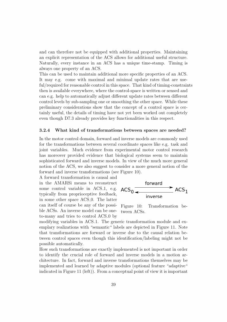
and can therefore not be equipped with additional properties. Maintainingan explicit representation of the ACS allows for additional useful structure.Naturally, every instance in an ACS has a unique time-stamp. Timing isalways one property of an ACS.This can be used to maintain additional more specific properties of an ACS.It may e.g. come with maximal and minimal update rates that are use-ful/required for reasonable control in this space. That kind of timing-constraintsthen is available everywhere, where the control-space is written or sensed andcan e.g. help to automatically adjust different update rates between differentcontrol levels by sub-sampling one or smoothing the other space. While thesepreliminary considerations show that the concept of a control space is cer-tainly useful, the details of timing have not yet been worked out completelyeven though D7.3 already provides key functionalities in this respect.
3.2.4 What kind of transformations between spaces are needed?
In the motor control domain, forward and inverse models are commonly usedfor the transformations between several coordinate spaces like e.g. task andjoint variables. Much evidence from experimental motor control researchhas moreover provided evidence that biological systems seem to maintainsophisticated forward and inverse models. In view of the much more generalnotion of the ACS, we also suggest to consider a more general notion of theforward and inverse transformations (see Figure 10).
ACSforward
inverse0 ACS1
Figure 10: Transformation be-tween ACSs.
A forward transformation is causal andin the AMARSi means to reconstructsome control variable in ACS 1, e.g.typically from proprioceptive feedback,in some other space ACS 0. The lattercan itself of course be any of the possi-ble ACSs. An inverse model can be one-to-many and tries to control ACS 0 bymodifying variables in ACS 1. The generic transformation module and ex-emplary realizations with “semantic“ labels are depicted in Figure 11. Notethat transformations are forward or inverse due to the causal relation be-tween control spaces even though this identification/labeling might not bepossible automatically.How such transformations are exactly implemented is not important in orderto identify the crucial role of forward and inverse models in a motion ar-chitecture. In fact, forward and inverse transformations themselves may beimplemented and learned by adaptive modules (optional feature “adaptive“indicated in Figure 11 (left)). From a conceptual point of view it is important
39

Transformation
ACS_0 ACS_1adaptive
Fwd Kinematics
joints EEPos
Fwd Modulation
CPG act gait
Inv Kinematics
EEPos joints
Inv Modulation
CPG actgait
Figure 11: Generic transformation module (left). Forward and inverse trans-formations connecting a task space, e.g. end effector coordinates, with jointspace (middle column). Forward and inverse mappings for gait control (rightcolumn).
that for every two ACS we can investigate if a forward and inverse modelexist and can try to learn it. If either such model is available then someother component of the architecture can work in one of the given spaces andincorporate feedback or sensing from the other.
3.3 The AMARSi Dynamical Systems approach
A key element of the AMARSi project is the consortium’s commitment fordynamical systems implementations of motor skill representations. As al-ready the deliverable D4.1. showed, there is a large variety of methods andapproaches available, with no single method being clearly superior in all re-spects to the others. We therefore need a flexible means to allow for a varietyof dynamical systems implementations which still captures the commonali-ties. In terms of the analysis of Section 2 that means to support heterogeneityon the level of the dynamical systems implementations, while ensuring a highdegree of homogeneity in the interfaces, which is realized through the notionof the AMARSi control spaces.
3.3.1 How is the AMARSi commitment for dynamical systemsimplementations reflected?
At the level of the concrete implementation of an ODE-based dynamicalsystem, we do not want to restrict the design space too much. We thereforeassume that a core element of the architecture, which is not further reducible,is an ODE implementation. It will always have a state space, some inputand output spaces (often parts of the state space if e.g. reservoirs are con-
40

ODE
statespace
inp out
status
ODE
ACS_1
ACS_N
ACS_1
ACS_M
Figure 12: Typical interface of an ODE module (left) and generic implemen-tation by a set of input and output ACSs (right).
sidered), which themselves are of course ACS, and a parametrization input(also forming an ACS), see Figure 12 (left).
statespace
inp out
status
Adaptive Module: ODE
targets
+ learning
Figure 13: An adaptive mod-ule is an ODE plus adaptationmechanism.
A particular important issue is what theoverall architecture, i.e. other componentscan know about the ODE status. Based onthe idea that modules are trained, we pro-pose to distinguish three basic states: tran-sient, converging, and reached. Transientmeans that the state of the module is insome untrained region and therefore it is atleast uncertain whether the ODE provides afunctionally meaningful output. Convergingmeans that the ODE state is in a trainedregion and approaches its desired behaviorin a controlled way. Reached means thatthe ODE is in a desired behavior, i.e. itmay have reached an attractor state, maybe tracking a reference signal with a desiredaccuracy or stably producing a pattern.This information will be very important for other components in order to’rely’ or not rely on the current output of the ODE. Technically, the ODEimplementation will hardly be restricted and allow for a large diversity ofapproaches. The status an ODE module can have are illustrated in Figure 14.
3.3.2 What is an adaptive module?
A dynamical systems implementation with relevant input and output ACSsas described above together with a learning method constitutes an adaptivemodule (see Figure 13). Many examples can be extracted from D4.1. (month
41

trainedregion
transient
converging
reached
output space of ODE
untrainedregion
Figure 14: Illustration of the transient, converging and reached statuses ofan ODE module.
12). In this notion, we distinguish between the ODE/discrete dynamicalsystems implementation and the adaptation mechanisms, which is to somedegree artificial because many of our examples generically include adaptationmechanisms. However, some ODEs are pre-trained and then not furtheradapted and then such a distinction seems useful.There is a second important issue connected with the notion of adaptation.Seen from an architectural viewpoint, there are two types of learning, whichare both very important in AMARSi. The simpler comprises is offline andonline supervised learning, which resides inside the very component (see Fig-ure 15 (left)). By providing target outputs, the adaptation then can be donelocally, without affecting further parts of the architecture.The second case concerns explorative or reinforcement learning approaches(see Figure 15 (right)), which need to collect feedback from the environmentbased on execution of the actual system. This case needs to be treated differ-ently, e.g. often certain other parts of the system have to be frozen, and thelearning mechanism might need access to more ACSs for perception and/orcontrol. The learner might actually also operate on a non-ODE implemen-tation of the control. It is therefore useful to distinguish learning and thedynamical system, at least on the conceptual level. Technically again thedesigners will need a large freedom to implement different adaptation andlearning schemes that shall not be strongly restricted by the software andimplementation framework.
42

statespace
inp out
status
Adaptive Module: ODE
targets
+supervised learning
statespace
inp out
status
Adaptive Module: ODE
reward
+reinforce- ment
Figure 15: Two typical adaptation mechanisms implemented by adaptivemodules: Supervised learning (left) requires an input ACS which providestargets for the output ACS. Reinforcement learning modules (right) are fedwith reward signals that do not belong to the output ACSs.
3.4 Modularization by Adaptive Components
3.4.1 Which level of modularization do we propose?
Adaptive Component
AM
control logic
Figure 16: The adaptive com-ponent module wraps an adap-tive module into a particularcontrol logic.
This is the key question of our architectureresearch program and the preliminary an-swer is a new notion: the adaptive com-ponent. An AMARSi Adaptive Com-ponent (AAC) is an adaptive module to-gether with its input and output ACSs, a ba-sic semantics (control logic) inside the com-ponent and timing management (see Fig-ure 16). One typical example is to checkwhether a reference point is reached by anattractor based ODE. We also assume thatthere is a parameterization of the adaptivecomponent itself which can activate/switchoff the whole component, but also parame-terize the respective logic, e.g. by setting a parameter for a convergence crite-rion. It is important that the adaptive component deals with time in a definedway: it either has to guarantee anytime-output, or give time-guarantees, ormay iterate until convergence. In all cases, other modules shall possibly knowabout this and for the designer it is a necessary condition to enable blueprint-ing of architectures of different adaptive modules in a coherent fashion.For a technical and software point of view, the conceptual AAC matches thecorresponding adaptive software component. Inputs and output are definedthrough the respective ACS connectors and the software components already
43
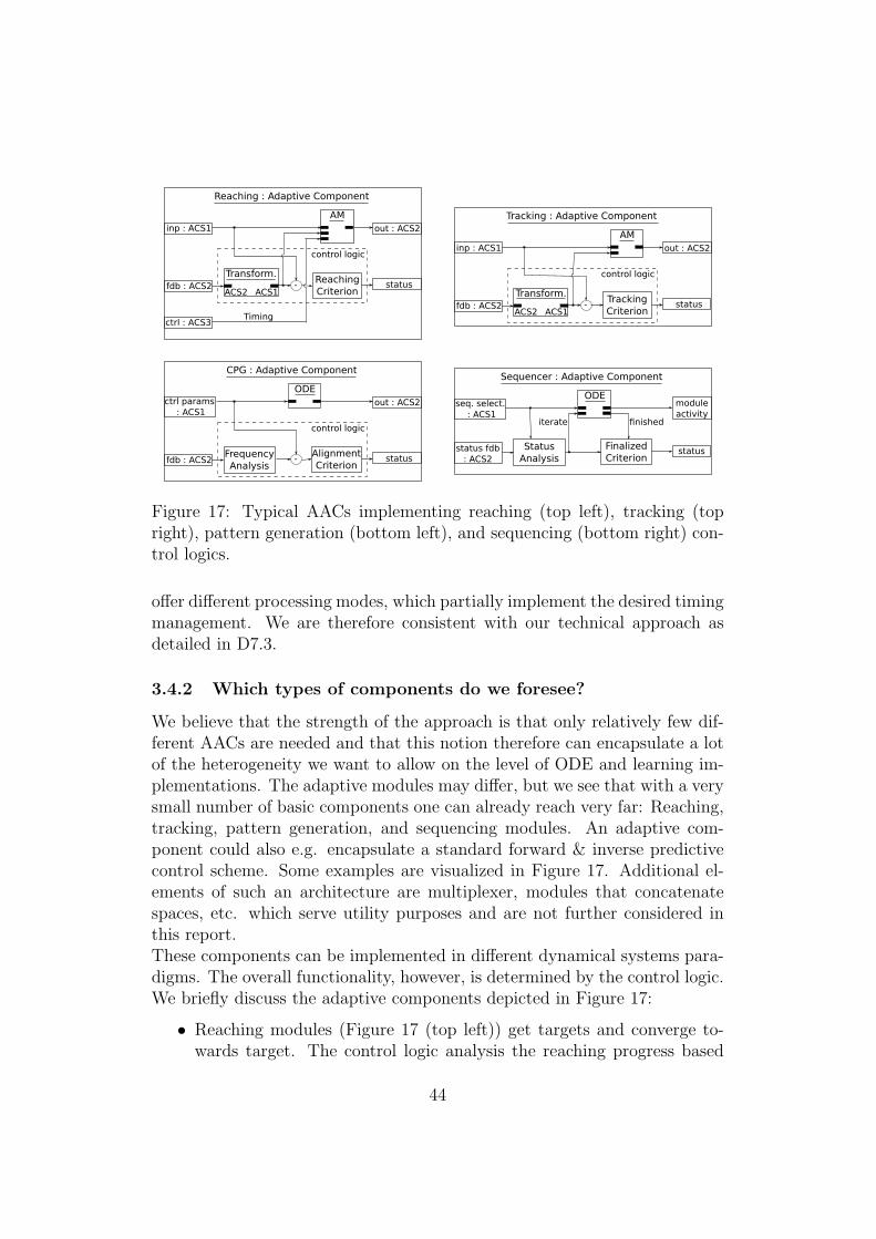
inp : ACS1 out : ACS2
status
Reaching : Adaptive Component
fdb : ACS2
AM
Transform.
ACS2 ACS1-
ReachingCriterion
control logic
ctrl : ACS3Timing
inp : ACS1 out : ACS2
status
Tracking : Adaptive Component
fdb : ACS2
AM
Transform.
ACS2 ACS1-
TrackingCriterion
control logic
ctrl params : ACS1
out : ACS2
status
CPG : Adaptive Component
fdb : ACS2
ODE
-AlignmentCriterion
control logic
FrequencyAnalysis
seq. select. : ACS1
module activity
status
Sequencer : Adaptive Component
status fdb : ACS2
ODE
FinalizedCriterion
finished
StatusAnalysis
iterate
Figure 17: Typical AACs implementing reaching (top left), tracking (topright), pattern generation (bottom left), and sequencing (bottom right) con-trol logics.
offer different processing modes, which partially implement the desired timingmanagement. We are therefore consistent with our technical approach asdetailed in D7.3.
3.4.2 Which types of components do we foresee?
We believe that the strength of the approach is that only relatively few dif-ferent AACs are needed and that this notion therefore can encapsulate a lotof the heterogeneity we want to allow on the level of ODE and learning im-plementations. The adaptive modules may differ, but we see that with a verysmall number of basic components one can already reach very far: Reaching,tracking, pattern generation, and sequencing modules. An adaptive com-ponent could also e.g. encapsulate a standard forward & inverse predictivecontrol scheme. Some examples are visualized in Figure 17. Additional el-ements of such an architecture are multiplexer, modules that concatenatespaces, etc. which serve utility purposes and are not further considered inthis report.These components can be implemented in different dynamical systems para-digms. The overall functionality, however, is determined by the control logic.We briefly discuss the adaptive components depicted in Figure 17:
• Reaching modules (Figure 17 (top left)) get targets and converge to-wards target. The control logic analysis the reaching progress based
44
on feedback and determines the modules status. The adaptive mod-ule provides timed reaching dynamics in the convergence phase, and isstatic in reached status.
• Tracking modules (Figure 17 (top right)) converge towards referencetrajectory. The convergence dynamics to the target trajectory is amixture of the adaptive modules dynamics and the input dynamics.The output of the tracking module displays externally driven dynamicsin reached status.
• Pattern generators (Figure 17 (bottom left)) outputs a pattern and isnot necessarily driven by a target. The control logic tracks the align-ment of the targeted pattern properties with the actual generated pat-tern incorporating feedback from the robot.
• Sequencing of modules (Figure 17 (bottom right)) can be understoodas special case of pattern generation with conditioned iteration of adynamical system. Feedback of module statuses that are controlled bythe sequencer enables the system to wait for the finalization of singlesteps in the sequence such that preconditions for following steps can beassured.
All these components are based on dynamical systems implementations.The dynamics can be parameterized (the parameters again constitute anACS), but also the logic (e.g. convergence criterion, switch on/off), timing-constraints etc. These parameters constitute the control space defined bythe respective adaptive component. Section 4 will in a preliminary exampleshow that with only few such AAC we can rephrase the discussed referencearchitectures.
3.5 The Architecture Level
3.5.1 How to realize learning on the architectural level?
Recent work inside and outside the AMARSi consortium has shown thatlearning techniques like reinforcement learning (e.g. [37, 36]) or goal directedexploration (e.g. [38]) can give excellent results. Within AMARSi, it hasbeen shown that reinforcement can even work on the new compliant COMANplatform [39]. These approaches have in common that either precise roboticmodels need to be available or the respective control spaces and the requiredfeedback need to be well known and rather low-dimensional. We concludethat our approach to explicitly organize control variables on all levels throughACS and corresponding transformations can help to provide consistent and
45
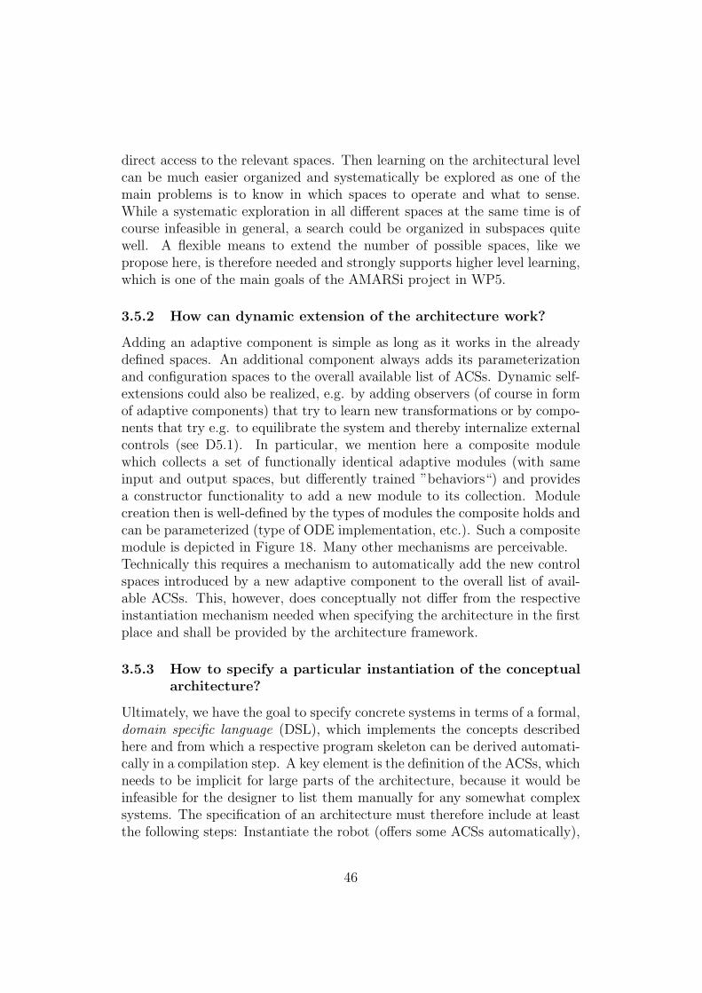
direct access to the relevant spaces. Then learning on the architectural levelcan be much easier organized and systematically be explored as one of themain problems is to know in which spaces to operate and what to sense.While a systematic exploration in all different spaces at the same time is ofcourse infeasible in general, a search could be organized in subspaces quitewell. A flexible means to extend the number of possible spaces, like wepropose here, is therefore needed and strongly supports higher level learning,which is one of the main goals of the AMARSi project in WP5.
3.5.2 How can dynamic extension of the architecture work?
Adding an adaptive component is simple as long as it works in the alreadydefined spaces. An additional component always adds its parameterizationand configuration spaces to the overall available list of ACSs. Dynamic self-extensions could also be realized, e.g. by adding observers (of course in formof adaptive components) that try to learn new transformations or by compo-nents that try e.g. to equilibrate the system and thereby internalize externalcontrols (see D5.1). In particular, we mention here a composite modulewhich collects a set of functionally identical adaptive modules (with sameinput and output spaces, but differently trained ”behaviors“) and providesa constructor functionality to add a new module to its collection. Modulecreation then is well-defined by the types of modules the composite holds andcan be parameterized (type of ODE implementation, etc.). Such a compositemodule is depicted in Figure 18. Many other mechanisms are perceivable.Technically this requires a mechanism to automatically add the new controlspaces introduced by a new adaptive component to the overall list of avail-able ACSs. This, however, does conceptually not differ from the respectiveinstantiation mechanism needed when specifying the architecture in the firstplace and shall be provided by the architecture framework.
3.5.3 How to specify a particular instantiation of the conceptualarchitecture?
Ultimately, we have the goal to specify concrete systems in terms of a formal,domain specific language (DSL), which implements the concepts describedhere and from which a respective program skeleton can be derived automati-cally in a compilation step. A key element is the definition of the ACSs, whichneeds to be implicit for large parts of the architecture, because it would beinfeasible for the designer to list them manually for any somewhat complexsystems. The specification of an architecture must therefore include at leastthe following steps: Instantiate the robot (offers some ACSs automatically),
46
Composite : Adaptive Component
AMTransform.
AM
ACS_1
ACS_N
ACS_1
ACS_MTransform.
optional
optional
ConstructorAM interfacespecification
add AM
ACSM1
add
Figure 18: A composite adaptive component provides a constructor func-tionality in addition to collecting multiple adaptive modules with identicalinterfaces. Automatic construction of a new adaptive module renders thearchitecture adaptive on a module level.
the adaptive components (also offer certain ACSs). Some combinations ofcontrol spaces are implicitly defined: If arbitration from several signals writ-ing to the same space is needed, implicitly the combination of these sourcespaces itself again constitutes an ACS. Composites of adaptive componentscan use internal composites of input spaces without providing outside accessby defining an explicit ACS (see Figure 18). Thereby, complexity can behidden to the outside and computational overhead can be reduced.Finally the designer needs to decide for a connectivity and timing that re-flects a certain architecture philosophy and to make it explicit in the domain-specific language by connecting the respective components. This approachsplits the architecture description into a blueprint and its implementation:First, the core structure of the architecture is defined utilizing the set of ba-sic modules (transformations, adaptive modules and components) and theirconnectivity. Second, particular implementations and properties (identifyingadaptive transformations with learning algorithms, ODE implementations,etc.) are assigned to each module in the archetype architecture. A strengthof this approach is that the designer is not forced to a single architectureprinciple: Hierarchies of ”layers” can be modeled by specific connectivity pat-terns (which may be expressed also algorithmically) but are not predefinedand rigid; homogeneous and heterogeneous architecture parts can be mixed.
3.6 Discussion
3.6.1 What is the no-free-lunch problem here?
One version of the no-free-lunch theorem is that no conceptual or technicalframework which fits a particular domain with elegant and small footprint
47

concepts comes without some hidden drawbacks, far reaching assumptionsor restrictions. The latter is of course true for our proposal here: We donot target a general solution for a general universal cognitive architecture.However, the very fact that many assumptions and restrictions from thedomain are included enables this attempt for a conceptualization in the firstplace. A further problem is that we propose to maintain a possibly longand partially useless list of ACS definitions and transformations, which mustbe represented explicitly. We expect to be capable of handling the ACSs,because the used middleware layer provides easy access and plenty of toolsexactly on this level. Implementing ACS as typed data, we can cope withthe effort to manage ACSs because the middleware provides some “importedlunch”: we can build on lots of previous and ongoing work outside AMARSi.A third problem of our concept is that there is no guideline how to realizethe component’s core, the adaptive module itself (but we have plenty ofapproaches available in AMARSi, see D4.1).
3.6.2 What are the open issues?
The probably most difficult open issue is to deal consistently with timing,because in our framework several time-scales need to be maintained: thereal world time (the robot!), possibly some architecture virtual “archtime”(needed e.g. for adjustment to simulators, robot sampling rates), ACS haveupdate times with respect to this “archtime” (but therefore also controlspaces in non-commensurable time-scales can be used by either sub-samplingthe one or interpolating the other), and the adaptive components have their“local virtual time” by means of time-steps defining the update rates of therespective implemented dynamical systems. To mediate between these dif-ferent timings we probably have to represent time very explicitly and havemechanisms to automatically “negotiate” time between ACS, adaptive com-ponents and real time constraints that may arise in components directlycontrolling robots. Here we need to collect more experience with the firstprototypes in order to come up with a consistent conceptualization of thehandling of time in our architecture framework.
3.6.3 Is there THE AMARSi Architecture orWhere do the semantics come from?
The conceptual framework unfolded in this Section provides a language andconcepts to formulate AMARSi architectures. It does itself not provide anyblueprints, it rather aims at providing the tools for efficient blueprinting.Many semantically different architectures can be formulated in this language
48

and at the current point of discussion we do not see limitations that wouldnot allow to implement the currently existing robotic control architectureswithin the consortium that have been described in Section 1. We envisagealso in the future AMARSi work a certain variety, which originates in thevariety of platforms and their quite different control spaces, in the variety oftasks, and in the ingenuity of the AMARSi researchers to provide new anduseful dynamical systems approaches for particular motor primitives.
4 Example architectures
Finally in this section, we spell out some examples that show how the existingarchitecture blueprints fit in the proposed scheme. The example “combina-tion of skills” demonstrates the feasibility to compactly describe a rathersimple and minimal complex architecture for “rich“ motor skills. Then, theEPFL B architecture (see Figure 6) is translated accordingly. Finally, a pro-posal by Jacobs for the hierarchical combination of simple pattern generatorsbased on the equilibration principle is spelled out.
4.1 Exemplary conceptual architecture for the combi-nation of skills
We first consider a reduced version of the architecture depicted in Figure 5that is presented in detail in D7.2 (Demonstration of Combined Skills). Werephrase this system in the proposed domain-specific language.The system in D7.2 produces a sequence of trotting and reaching phases asfollows: A sequencer triggers trotting or reaching behaviors by sending ap-propriate reaching goals and oscillator amplitudes to respective submodules.The reaching module computes smooth joint angles trajectories from a targetposition provided by the sequencer module. Note that the inverse kinemat-ics for an Oncilla leg are already encapsulated in the reaching module (cf.Figure 17 (top left)). The trotting gait is produced by two ODE modules:The Hopf oscillator acts as canonical system (cf. Section 1.4 and D4.1) anddrives the transformation system of the DMP. The transformation systemcontains eight CPGs for all eight joint angles which finally drive the Oncillarobot. Feedback of joint angles enable the reaching (and the subsequentDMP module) to adapt to external perturbations. The system generates os-cillating joint angles, i.e. trotting, when the amplitude of the Hopf oscillatoris greater than zero. Otherwise, the Hopf oscillator converges to a fixed-pointmodulated by the reaching controller.
49

SequencerEEPos
amplitude Hopf Osc.
amp. phase
Oncillaleg jointsleg forces
Reachingtargetjoints joints
DMP Trans.
phasejoints
joints
Figure 19: Combination of skills example expressed as domain-specific con-trol architecture: The displayed system generates sequences of alternatingwalking and reaching behaviors. Utilizing the domain-specific architecturecomponents, the system’s formulation is compact. Abstraction of the par-ticular implementations of the adaptive modules extracts the underlyingarchetype architecture.
The compact representation of this minimal complex example points out thestrength of a domain-specific modeling: Many details about the explicit im-plementation are hidden (we refer to D7.2 which spells this system out onthe experimentation levell, and to D7.3 for a software formulation). And, theparticular implementation of the constituents of this (exemplary) archetypearchitecture may be exchanged without changing the “semantics” of the sys-tem.
4.2 EPFL B architecture
The architecture from EPFL B (group Billard, Section 1.4) directly mapson the proposed scheme. Figure 20 displays the architecture in Figure 6rephrased in the AMARSi conceptual architecture framework. Robot con-troller on joint level are encapsulated in the robot arm module and kinematictransformations are part of the reaching module. The targets of reachingmovements may come from outside of the core AMARSi architecture dedi-cated to motor skills using one of the multiple interfacing technologies pro-vided by the AMARSi software. Also, the creation and training of the adap-tive reaching component by kinesthetic teaching with the help of a human isexternalized in Figure 20 according to the current system’s implementation.Analogously, the architecture in Figure 2 translates to the unified AMARSirepresentation of architectures which emphasizes the representational powerof the proposed scheme. Despite the compact representation of such rathersimple architectures using the proposed domain-specific modules, this is apreliminary scheme and the tight integration of learning and interaction has
50

RobotArmjointsforces
Reachingtargetjoints joints
visual targettracker
kinestheticteaching
create
Figure 20: Rephrased architecture from Figure 6.
to be further elaborated. These issues will be tackled in T6.5 and T7.5.
4.3 Body coordination architecture
In this section, we propose an architecture design scheme for what in the workof the iCub consortium would have been called ”phylogenetic” subsystems(cf. Section 1.6). We denote this architecture scheme by body coordination(BC). It comprises (only) two layers, a layer of CPGs and a layer coordinat-ing these CPGs. We will not present one particular, concrete such systems(unlike the Version 0.4 iCub consortium architecture, where this was done).Instead, we describe a design scheme for BC architectures which is detailedenough to concretely guide the creation of such systems, and likewise detailedenough to become supported by dedicated software modules (objects, datatypes, communication channels). Once instantiated and implemented on arobot, such a BC system will not be subject to structural change by learning;it will only be open to parameter optimization.Because of the reasons given in Section 2, we do not aspire, at this point, atan architecture unification on higher cognitive levels beyond these layers.The particular objectives of AMARSi impose particular requirements on theBCS design scheme, which are different from the iCub project. In thatproject, the objective was to come as close as possible to the human orig-inal, which led to the cognitive neuroscience oriented models sketched inSection 1.6. In particular, this led to a detailed model of one particular basicmotor behavior, visually guided grasping. In AMARSi, the overarching ob-jective is to master the integration of many motion patterns.The main goalof the proposed BC design scheme is therefore to give a principled account ofhow many ”phylogenetically fixed” motion patterns can be coordinated by
51

Figure 21: The body coordination scheme builds two layers on top of theactuator’s control spaces. Actuation is accomplished by pattern generators(PGs) (middle layer). The pattern generators themselves are “steered” by socalled body coordination (BC) units (top layer).
a likewise fixed coordination layer. Which motion patterns are chosen for aparticular instantiation of the BC scheme is left to the system designer.A note on terminology. We will call the adaptive components in the lowerof our two layers pattern generators (PGs), and the adaptive components inthe higher layer body coordination (BC). While we might also have chosenestablished terms, like central pattern generators or behaviors, respectively,we wanted to avoid the load of associations connected with any such well-known term. As will become clear, PGs can become instantiated by anyof the ”CPG” models that exist in the consortium; the BCs however haveno direct precedent and incorporate an innovative bundle of functionalities.For the time being, it may help the reader’s imagination to think of PGs asany of the known ”CPG” systems, and of the BCs as coordinated motionpatterns that typically (though not necessarily) involve the entire body, like”standing up”, ”walking”, ”crawling”. A sketch of the architecture schemeis depicted in Figure 21.We will account only for, and exactly for, motion patterns which can be un-derstood as coordination between motor actuation, proprio-perception, andexternal perception of the own body and the immediate physical environ-
52
ment – for instance, seeing one’s own feet or hands, or the ground, or a closeobstacle. Whether gravitational/acceleration and touch sensing is classifiedas proprioceptive or external is left to the designer; these intrinsically re-late the own body with its immediate environment (compare discussion inSection 3.2). One could paraphrase this scope as ”the BC system is whatallows the robot to experience its own body as a controllable object in theimmediate physical environment”.We point out that the iCub project architecture V0.4 for visually guidedreaching implements one particular body coordination, understood in thesense just paraphrased. Our BC design scheme will not be as detailed asthis iCub V0.4 architecture is, but to compensate for this lack in detail of aparticular BC will provide answers to how several BCs can be coordinated.Specifically, with our BC design scheme we want to provide principled an-swers to the following nontrivial challenges:
• Dynamic combination of PGs. A PG will generate a pattern that is sentto only a subset of the actuators of a robot. A BC will therefore have torecruit several PGs and coordinate their dynamics. This coordinationshould not only be an open-loop, top-down ”activation” BC → PG,but be self-stabilizing through feedback PG → BC.
• Dynamic combination of BCs. Different BCs may or may not be ex-ecutable simultaneously. Most pairings will be mutually conflicting.However, some combinations make sense – for instance, walking whilesimultaneously reaching forward with the hands. It must be ensuredthat (i) only compatible pairings can be simultaneously active, and (ii)that when several PCs are active, the signals sent to the PG level arecompatible with each other.
• Three mechanisms of coupling PGs. We have to combine three couplingmechanism that appear unavoidable (and which are all realized in bio-logical systems): (i) coupling through body physics, mediated by pro-prioceptive feedback; (ii) ”lateral” coupling between PGs, mediated bycoupling parameters; (iii) ”top-down” couplings through coordinatedactivations by the BCs.
• Fusing proprioceptive and external sensor information. Stated in in-tuitive terms, we want to attain a seamless integration between theexternal body-in-immediate-environment perception, and the proprio-ceptive ”body feeling”. These two sources of information should mergeinto a unity; when they fall apart, a conflict situation arises that wouldhave to be repaired by suitable motor action.
53

BCtargetext P_tarvisual
perception
targetbehavior
RobotArmLjointsforces
RobotArmRjointsforces
RobotLegRjointsforces
CPG
phaseamp
joints
CPG
phaseamp
joints
CPG
phaseamp
joints
int
BCtargetext P_tarint
Figure 22: The body coordination scheme from Figure 21 rephrased in termsof adaptive components.
We unfold our proposal in more detail and adopt its description to thedomain-specific terms proposed in Section 3. The lowest level in the BCscheme are the actuation interfaces of the robot. The middle layer comprisesa set of m CPG components as described in Section 3.4.1. The CPGs outputjoint angles that are fed to the robot control inputs. Note that arbitra-tion/selection of multiple CPG inputs to the same control space of the robotis handled by the middleware. Technically, the CPGs write to the ports of therobot component if the CPGs are activated. Finally, the top layer comprisesn BC modules which are a novel type of adaptive components implementinga particular tracking control mechanism. BCs are modules for the active co-ordination between externally sensed percepts (e.g. 2-d position of visuallyperceived fingertip, or speed based on optic flow, or posture based on gyrosensors) and internal body percepts based on proprioceptive sensing. Theseperception channels are all implemented as ACSs. Figure 22 illustrates theBC architecture scheme by respectively labeled boxes and connections usingthe notations from Section 3.In the following, the new type of adaptive component, namely the BCs, aredescribed in more detail. Each BC will have three submodules:
54
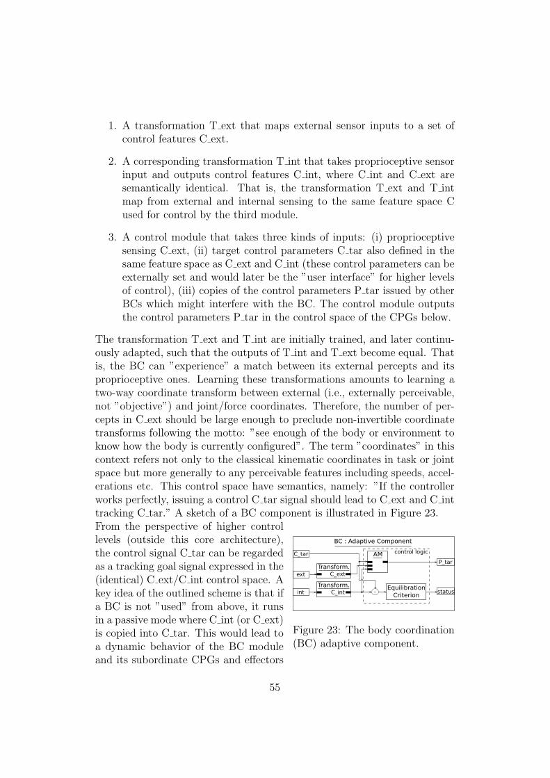
1. A transformation T ext that maps external sensor inputs to a set ofcontrol features C ext.
2. A corresponding transformation T int that takes proprioceptive sensorinput and outputs control features C int, where C int and C ext aresemantically identical. That is, the transformation T ext and T intmap from external and internal sensing to the same feature space Cused for control by the third module.
3. A control module that takes three kinds of inputs: (i) proprioceptivesensing C ext, (ii) target control parameters C tar also defined in thesame feature space as C ext and C int (these control parameters can beexternally set and would later be the ”user interface” for higher levelsof control), (iii) copies of the control parameters P tar issued by otherBCs which might interfere with the BC. The control module outputsthe control parameters P tar in the control space of the CPGs below.
The transformation T ext and T int are initially trained, and later continu-ously adapted, such that the outputs of T int and T ext become equal. Thatis, the BC can ”experience” a match between its external percepts and itsproprioceptive ones. Learning these transformations amounts to learning atwo-way coordinate transform between external (i.e., externally perceivable,not ”objective”) and joint/force coordinates. Therefore, the number of per-cepts in C ext should be large enough to preclude non-invertible coordinatetransforms following the motto: ”see enough of the body or environment toknow how the body is currently configured”. The term ”coordinates” in thiscontext refers not only to the classical kinematic coordinates in task or jointspace but more generally to any perceivable features including speeds, accel-erations etc. This control space have semantics, namely: ”If the controllerworks perfectly, issuing a control C tar signal should lead to C ext and C inttracking C tar.” A sketch of a BC component is illustrated in Figure 23.
ext
P_tar
status
BC : Adaptive Component
int
AM
Transform.C_int -
EquilibrationCriterion
control logicC_tar
Transform.C_ext
Figure 23: The body coordination(BC) adaptive component.
From the perspective of higher controllevels (outside this core architecture),the control signal C tar can be regardedas a tracking goal signal expressed in the(identical) C ext/C int control space. Akey idea of the outlined scheme is that ifa BC is not ”used” from above, it runsin a passive mode where C int (or C ext)is copied into C tar. This would lead toa dynamic behavior of the BC moduleand its subordinate CPGs and effectors
55
as an ”equilibrated” subsystem which is dynamically in an indifferent equi-librium, i.e. has no tendency of its own to change ongoing CPG dynamics(which would be under the control of other, currently ”used” BCs).Learning of BCs targets at generating control parameters P tar for the lowerlevel CPGs such that —C int - C tar— becomes minimal. That is, a BClearns which P tar it should issue to the CPGs below such that the targetedfunctionality arises. A possible candidate algorithm for this training has beendeveloped at Jacobs University and has been applied to Echo State Networksas mixed open/closed loop tracking controllers [40, 41]. The general learningscheme is, however, not restricted to Echo State Networks and could beadapted to BCs based on other ODE formalisms.In summary, the BC level provides an interface to higher control levels whichprovides (i) a set of externally perceived features (over all BCs), (ii) a setof internally perceived features, which ideally are identical to the externallyperceived ones, and (iii) a trained control mechanism implemented by anadaptive module which makes the externally/internally sensed features trackdesired targets. In the most intuitive terms, this architecture can be un-derstood as providing the robot with an ”effective feeling of a controllablebody in an externally perceived body space”. The above architecture tex-tual description and Figure 22 already utilized the concepts introduced inSection 3.The outlined BC architecture is one example how to organize many modulesin a hierarchical scheme with homogeneous layers. It is an initial sketch andis meant to illustrate that particular, “formalized” connectivity schemes maylead to extended architecture blueprints which can easily be expressed in theproposed domain-specific nomenclature proposed in Section 3.
5 Conclusion
This report identifies a set of fundamental concepts and principles in ar-chitecture design. A domain-specific treatment of the architecture problemis proposed that is based on the commitment to dynamical systems. Thisformalization ultimately results in a domain-specific programming languagethat enables blueprinting of architectures by separating implementation de-tails of single modules from the overall architecture conception. Thereby,the restriction to the domain of dynamical systems with their rather clearcutproperties and features circumvents the pure assignment of functionalities toboxes by labeling. This approach sets a basis for the further software de-velopment in tight cooperation with the AMARSi concepts. The presentedscheme is already promising with respect to the compact representation of
56

the existing architectures in the AMARSi consortium. Additionally, a novelcomponent is introduced that enables the coordination of multiple standardAMARSi modules and whose functionality is an important extension to thecurrent AMARSi architectures.
References
[1] S. Wrede, M. Johannfunke, A. Lemme, A. Nordmann, S. Ruther,A. Weirich, and J. J. Steil. Interactive learning of inverse kinemat-ics with nullspace constraints using recurrent neural networks. In 20.Workshop on Computational Intelligence, Dortmund, 2010. Fachauss-chuss Computational Intelligence der VDI/VDE-Gesellschaft Mess- undAutomatisierungstechnik.
[2] Y.P. Ivanenko, R.E. Poppele, and F. Lacquantini. Motor control pro-grams and walking. The Neuroscientist, 12(4):339–348, 2006.
[3] A. d’Avella, L. Fernandez, A. Portone, and F. Lacquantini. Modulationof phasic and tonic muscle synergies with reaching direction and speed.J. Neurophysiol., 100:1433–1454, 2008.
[4] A.J. Ijspeert, J. Nakanishi, H. Hoffmann, P. Pastor, and S. Schaal. Dy-namical Movement Primitives: Learning Nonlinear Attractor Models forMotor Behaviors, 2011. Submitted.
[5] S.L. Degallier, L. Righetti, S. Gay, and A. J. Ijspeert. Toward sim-ple control for complex, autonomous robotic applications: Combiningdiscrete and rhythmic motor primitives, 2011. Submitted.
[6] E. Gribovskaja, S. M. Khansari-Zadeh, M. Seyed, and A. Billard. Learn-ing nonlinear multivariate dynamics of motion in robotic manipulators.Int. J. of Robotics Research. Accepted.
[7] S.M. Khansari-Zadeh and A. Billard. Learning Stable Non-Linear Dy-namical Systems with Gaussian Mixture Models. IEEE Transaction onRobotics, 2011. In press.
[8] S.M. Khansari-Zadeh and A. Billard. A Dynamical System Approach toRealtime Obstacle Avoidance. Autonomous Robots, 2011. Submitted.
[9] H. Jaeger and Th. Christaller. Dual Dynamics: Designing BehaviorSystems for Autonomous Robots. Artificial Life and Robotics, 2:108–112, 1998.
57

[10] S. Behnke and R. Rojas. A hierarchy of reactive behaviors handles com-plexity. In Proceedings of: Balancing Reactivity and Social Deliberationin Multi-Agent Systems, a Workshop at ECAI the 14th European Con-ference on Artificial Intelligence, Berlin, 2000.
[11] H. Jaeger. Discovering multiscale dynamical features with hierarchicalEcho State Networks. Technical Report 10, Jacobs University, 2007.
[12] M. Lukosevicius. On self-organizing reservoirs and their hierarchies.Technical Report 25, Jacobs University, 2010.
[13] V. Sakenas. Distortion Invariant Feature Extraction with Echo StateNetworks. Technical Report 24, Jacobs University, 2010.
[14] D. Vernon, G. Sandini, and G. Metta. The iCub Cognitive Architecture:Interactive development in a humanoid robot. In In Proceedings of IEEEInternational Conference on Development and Learning (ICDL), Impe-rial College, London, 2007.
[15] D. Vernon. A Roadmap for the Development of Cogni-tive Capabilities in Humanoid Robots. Technical report, De-liverable D2.1 of the RobotCub FP6 project, University ofGenoa, 2009. http://www.robotcub.org/index.php/robotcub/moreinformation/deliverables/deliverable 2 1 pdf.
[16] R. Brooks. The whole Iguana. pages 432–456. MIT Press, 1989.
[17] Y. Takahashi and M. Asada. Behavior Acquisition by Multi-LayeredReinforcement Learning. In Proceeding of the 1999 IEEE InternationalConference on Systems, Man, and Cybernetics, pages 716–721, 1999.
[18] J.S. Albus. A Reference Model Architecture for Intelligent Systems De-sign, chapter 2, pages 27–56. Kluwer Academic Publishers, 1993.
[19] W. T. Powers. An Outline of Control Theory, pages 253–293. TheControl Systems Group, Inc., 1989.
[20] H. Miyamoto, S. Schaal, F. Gandolfo, H. Gomi, Y. Koike, R. Osu,E. Nakano, Y. Wada, and M. Kawato. A Kendama learning robot basedon bi-directional theory. Neural Networks, 9(8):1281–1302, 1996.
[21] Marc Toussaint and Christian Goerick. A Bayesian view on motor con-trol and planning. In Olivier Sigaud and Jan Peters, editors, From Mo-tor Learning to Interaction Learning in Robots, volume 264 of Studies
58
in Computational Intelligence, pages 227–252. Springer Berlin / Heidel-berg, 2010.
[22] P. F. Dominey. Shared Intentional Plans for Imitation and Cooperation:Integrating Clues from Child Development and Neurophysiology intoRobotics. In Proceedings of 4th International Symposium on Imitationin Animals and Artifacts at AISB’07, pages 66–73, 2007.
[23] S. Thrun et al. Stanley: The Robot that Won the DARPA GrandChallenge. Journal of Field Robotics, 23(9):661–692, 2006.
[24] C. Goerick, B. Bolder, H. Janssen, M. Gienger, H. Sugiura,I. Mikhailova, T. Rodemann, H. Wersing, and S. Kirstein. Towardsincremental hierarchical behavior generation for humanoids. In Proc. of7th IEEE-RAS Int. Conf. on Humanoid Robots, pages 248–255, 2009.
[25] T.J. Prescott, P. Redgrave, and K. Gurney. Layered control architec-tures in robots and vertebrates. Adaptive Behavior, 7(1):99–127, 1999.
[26] H. Cruse, D. E. Brunn, C. Bartling, J. Dean, M. Dreifert, T. Kinder-mann, and J. Schmitz. Walking: A complex behavior controlled bysimple networks. Adaptive Behavior, 3(4):385–418, 1995.
[27] Y. Yamashita and J. Tani. Emergence of Functional Hierarchy in aMultiple Timescale Neural Network Model: A Humanoid Robot Exper-iment. PLOS Computational Biology, 4(11), 2008.
[28] G. Schoner, H. Haken, and J.A.S. Kelso. A Stochastic Theory ofPhase Transitions in Human Hand Movement. Biological Cybernetics,(53):247–257, 1986.
[29] R. Lowe, A. Montebelli, I. Ieropoulos, C. Melhuish, J. Greenman, andT. Ziemke. Towards an Energy-Motivation Autonomous Robot: A Studyof Artificial Metabolic Constrained Dynamics. In Proceedings of the12th International Conference on the Synthesis and Simulation of LivingSystems, pages 725–732. MIT Press, 2010.
[30] D. McFarland and T. Bosser. Intelligent Behavior in Animals andRobots. MIT Press, 1993.
[31] J.R. Anderson, D. Bothell, M. D. Byrne, S. Douglass, C. Lebiere, andY. Qin. An integrated theory of the mind. Psychological Review,111(4):1036–1060, 2004.
59

[32] Daniel M. Wolpert, R. Chris Miall, and Mitsuo Kawato. Internal modelsin the cerebellum. Trends in Cognitive Sciences, 2(9):338–347, 1998.
[33] Michael I. Jordan. Computational aspects of motor control and motorlearning. In Herbert Heuer and Steven W. Keele, editors, Motor skills,volume 2 of Handbook of Perception and Action, pages 71–120. AcademicPress, 1996.
[34] Daniel M. Wolpert and Zoubin Ghahramani. Computational principlesof movement neuroscience. Nature Neuroscience, 3:1212–1217, 2000.
[35] O. Khatib. A unified approach for motion and force control of robotmanipulators: The operational space formulation. IEEE Journal ofRobotics and Automation, 3(1):43–53, 1987.
[36] Jan Peters and Stefan Schaal. Learning to control in operational space.The International Journal of Robotics Research, 27(2):197–212, 2008.
[37] Evangelos Theodorou, Jonas Buchli, and Stefan Schaal. Learning policyimprovements with path integrals. In Proceedings of the 13th Interna-tional Conference on Artificial Intelligence and Statistics (AISTATS),pages 828–835, 2010.
[38] M. Rolf, J.J. Steil, and M. Gienger. Goal babbling permits direct learn-ing of inverse kinematics. IEEE Transactions on Autonomous MentalDevelopment, 2(3):216–229, 2010.
[39] Petar Kormushev, Barkan Ugurlu, Sylvain Calinon, Nikolaos G.Tsagarakis, and Darwin G. Caldwell. Bipedal walking energy minimiza-tion by reinforcement learning with evolving policy parameterization. InIEEE/RSJ International Conference on Intelligent Robots and Systems(IROS), pages 318–324, 2011.
[40] Herbert Jaeger. Reservoir self-control for achieving invariance againstslow input distortions. Technical Report 23, Jacobs University, October2010.
[41] Jiwen Li and Herbert Jaeger. Minimal energy control of an esn patterngenerator. Technical Report 26, Jacobs University, February 2011.
60