id 610c: introduction to bldc motor control avnet jim carver technical director, advanced...
TRANSCRIPT
ID 610C: Introduction to BLDC Motor Control
Avnet
Jim Carver
Technical Director, Advanced Architectures
12 October 2010
Version 1.0

2
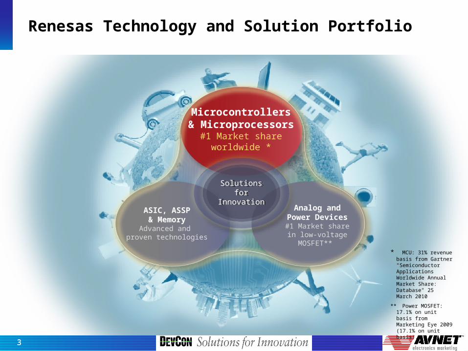
Renesas Technology and Solution Portfolio
Microcontrollers& Microprocessors
#1 Market shareworldwide *
Analog andPower Devices#1 Market share
in low-voltageMOSFET**
Solutionsfor
Innovation
Solutionsfor
InnovationASIC, ASSP& Memory
Advanced and proven technologies
* MCU: 31% revenue basis from Gartner "Semiconductor Applications Worldwide Annual Market Share: Database" 25 March 2010
** Power MOSFET: 17.1% on unit basis from Marketing Eye 2009 (17.1% on unit basis).
33
Renesas Technology and Solution Portfolio
Microcontrollers& Microprocessors
#1 Market shareworldwide *
Analog andPower Devices#1 Market share
in low-voltageMOSFET**
ASIC, ASSP& Memory
Advanced and proven technologies
* MCU: 31% revenue basis from Gartner "Semiconductor Applications Worldwide Annual Market Share: Database" 25 March 2010
** Power MOSFET: 17.1% on unit basis from Marketing Eye 2009 (17.1% on unit basis).
Solutionsfor
Innovation
Solutionsfor
Innovation
44
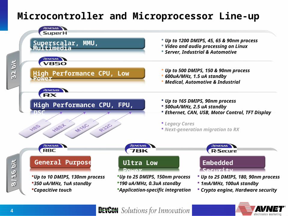
Microcontroller and Microprocessor Line-up
Superscalar, MMU, Multimedia Up to 1200 DMIPS, 45, 65 & 90nm process Video and audio processing on Linux Server, Industrial & Automotive
Up to 500 DMIPS, 150 & 90nm process 600uA/MHz, 1.5 uA standby Medical, Automotive & Industrial
Legacy Cores Next-generation migration to RX
High Performance CPU, FPU, DSC
Embedded Security
Up to 10 DMIPS, 130nm process350 uA/MHz, 1uA standbyCapacitive touch
Up to 25 DMIPS, 150nm process190 uA/MHz, 0.3uA standbyApplication-specific integration
Up to 25 DMIPS, 180, 90nm process 1mA/MHz, 100uA standby Crypto engine, Hardware security
Up to 165 DMIPS, 90nm process 500uA/MHz, 2.5 uA standby Ethernet, CAN, USB, Motor Control, TFT Display
High Performance CPU, Low Power
Ultra Low PowerGeneral Purpose
55
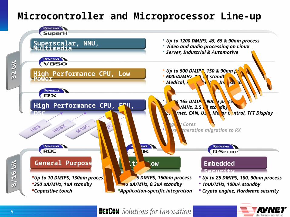
Microcontroller and Microprocessor Line-up
Superscalar, MMU, Multimedia Up to 1200 DMIPS, 45, 65 & 90nm process Video and audio processing on Linux Server, Industrial & Automotive
Up to 500 DMIPS, 150 & 90nm process 600uA/MHz, 1.5 uA standby Medical, Automotive & Industrial
Legacy Cores Next-generation migration to RX
High Performance CPU, FPU, DSC
Embedded Security
Up to 10 DMIPS, 130nm process350 uA/MHz, 1uA standbyCapacitive touch
Up to 25 DMIPS, 150nm process190 uA/MHz, 0.3uA standbyApplication-specific integration
Up to 25 DMIPS, 180, 90nm process 1mA/MHz, 100uA standby Crypto engine, Hardware security
Up to 165 DMIPS, 90nm process 500uA/MHz, 2.5 uA standby Ethernet, CAN, USB, Motor Control, TFT Display
High Performance CPU, Low Power
Ultra Low PowerGeneral Purpose
6
Agenda
Motor Types Overview
BLDC Motor Applications
Comparison of DC to Brushless DC Motors
Hall Sensors
Six-Step Commutation
Sensorless Commutation with Back-EMF
Vector Motor Control basics
Closed-Loop Speed Control
Introduction to BLDC Motor Control Evaluation Kit
Summary
7
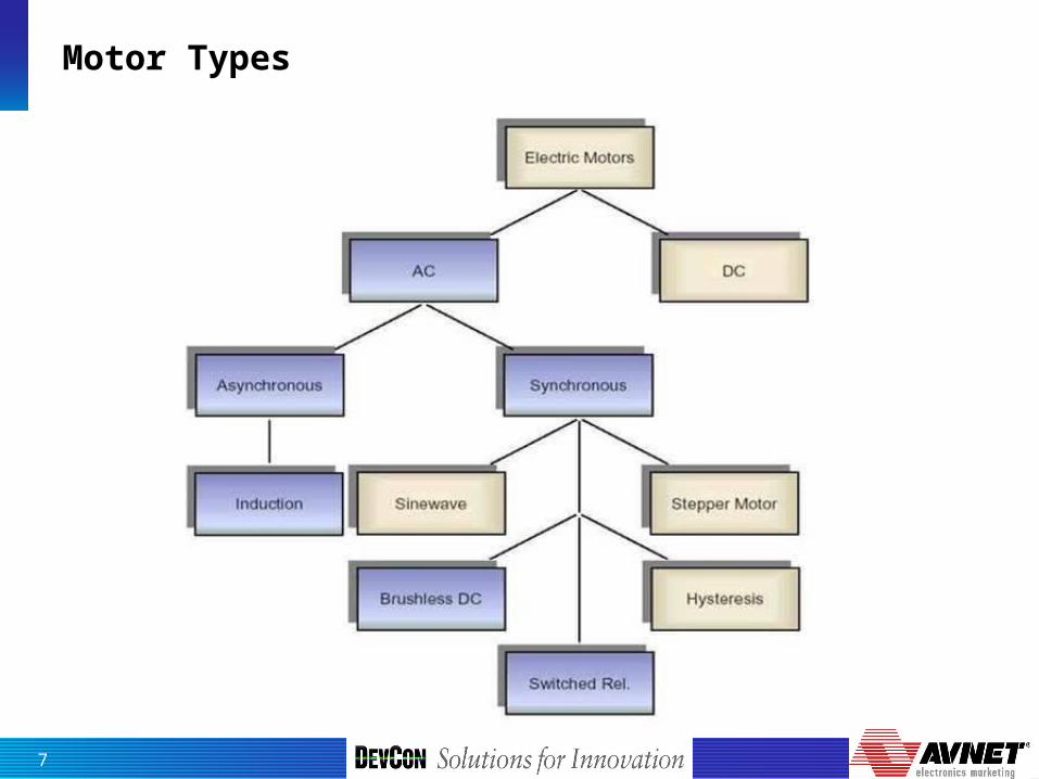
Motor Types
8
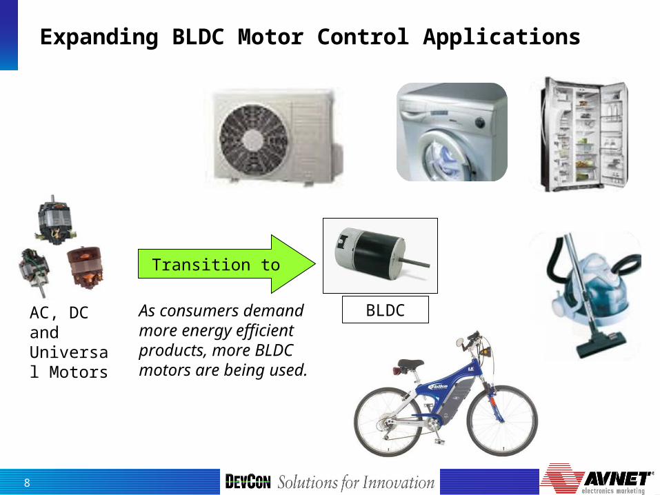
Expanding BLDC Motor Control Applications
AC, DC and Universal Motors
Transition to
BLDCAs consumers demand more energy efficient products, more BLDC motors are being used.
9
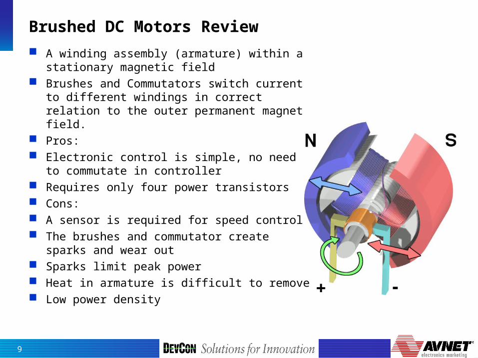
Brushed DC Motors Review
A winding assembly (armature) within a stationary magnetic field
Brushes and Commutators switch current to different windings in correct relation to the outer permanent magnet field.
Pros: Electronic control is simple, no need to
commutate in controller Requires only four power transistors Cons: A sensor is required for speed control The brushes and commutator create sparks
and wear out Sparks limit peak power Heat in armature is difficult to remove Low power density
10
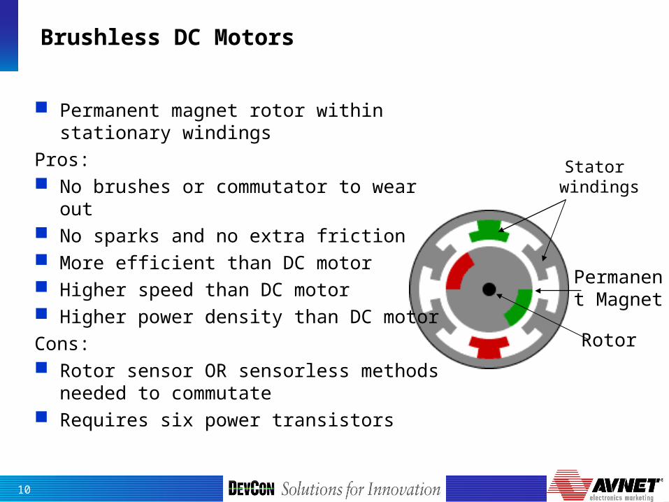
Brushless DC Motors
Permanent Magnet
Rotor
Stator windings
Permanent magnet rotor within stationary windings
Pros: No brushes or commutator to wear out No sparks and no extra friction More efficient than DC motor Higher speed than DC motor Higher power density than DC motorCons: Rotor sensor OR sensorless methods
needed to commutate Requires six power transistors

11
Brushed DC Commutation
The windings in the armature are switched to the DC power by the brushes and armature
Each winding sees a positive voltage, then a disconnect, then a negative voltage
The field produced in the armature interacts with the stationary magnet, producing torque and rotation
+
-
N S
U
+
-
U

12
DC Motor Bridge
The DC motor needs four transistors to operate the DC motor
The combination of transistor is called an H-Bridge, due to the obvious shape
Transistors are switched diagonally to allow DC current to flow in the motor in either direction
The transistors can be Pulse Width Modulated to reduce the average voltage at the motor, useful for controlling current and speed 0
1
1
1
0
0
0
13
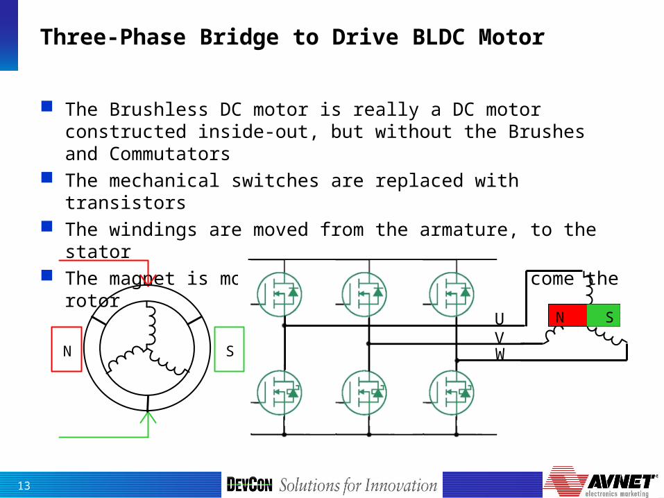
Three-Phase Bridge to Drive BLDC Motor
The Brushless DC motor is really a DC motor constructed inside-out, but without the Brushes and Commutators
The mechanical switches are replaced with transistors The windings are moved from the armature, to the stator The magnet is moved from the outside to become the rotor
N S
N S
UVW
14
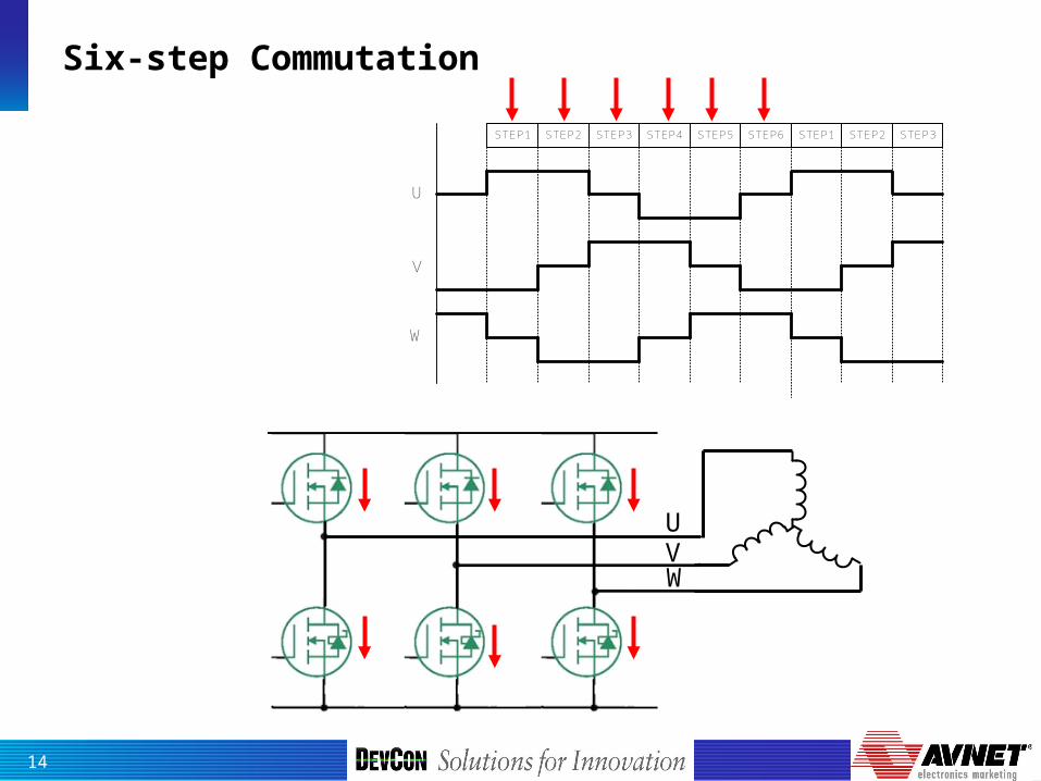
Six-step Commutation
STEP1 STEP2 STEP3 STEP4 STEP5 STEP6 STEP1 STEP2 STEP3
U
V
W
UVW
15
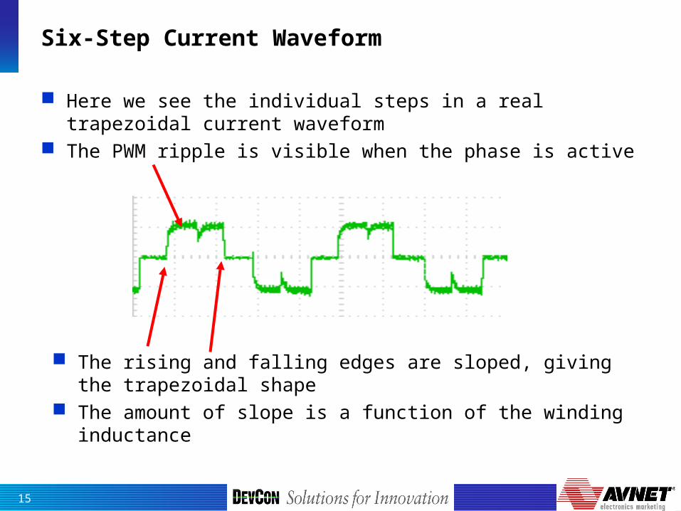
Six-Step Current Waveform
Here we see the individual steps in a real trapezoidal current waveform
The PWM ripple is visible when the phase is active
The rising and falling edges are sloped, giving the trapezoidal shape
The amount of slope is a function of the winding inductance
16
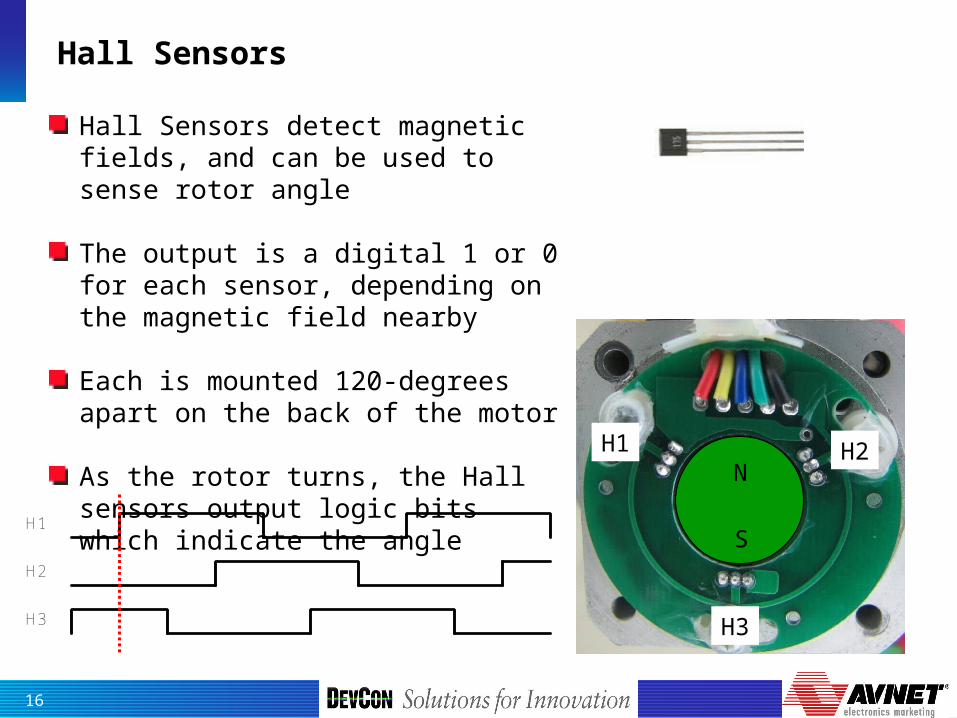
Hall Sensors
Hall Sensors detect magnetic fields, and can be used to sense rotor angle
The output is a digital 1 or 0 for each sensor, depending on the magnetic field nearby
Each is mounted 120-degrees apart on the back of the motor
As the rotor turns, the Hall sensors output logic bits which indicate the angle
H1
H2
H3
N
S
H1 H2
H3
17
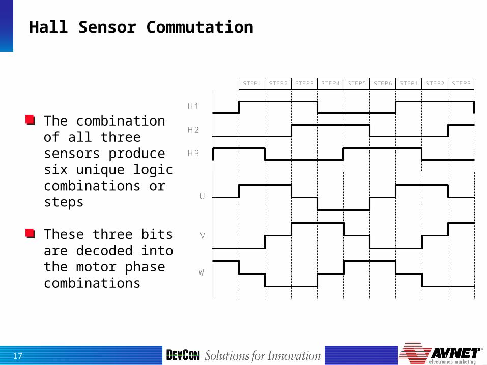
Hall Sensor Commutation
H1
H2
H3
STEP1 STEP2 STEP3 STEP4 STEP5 STEP6 STEP1 STEP2 STEP3
The combination of all three sensors produce six unique logic combinations or steps
These three bits are decoded into the motor phase combinations
U
V
W
18
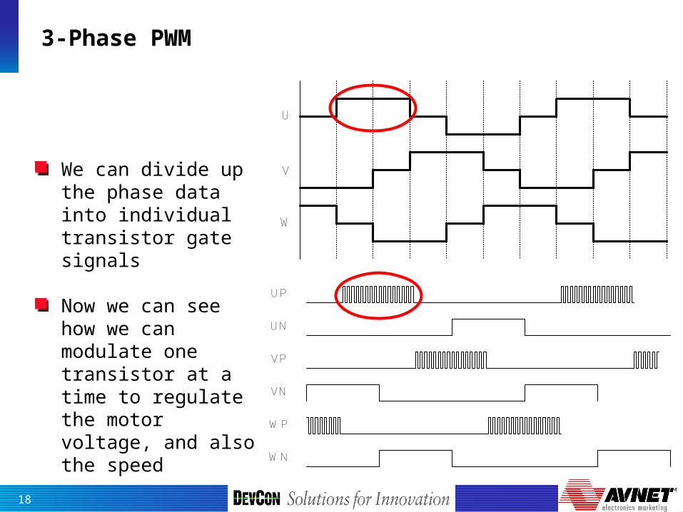
3-Phase PWM
U
V
W
We can divide up the phase data into individual transistor gate signals
Now we can see how we can modulate one transistor at a time to regulate the motor voltage, and also the speed
UP
UN
VP
VN
WP
WN
19
Sensorless Commutation
Instead of using sensors like Halls, we can let the motor tell us which phase should be energized
The Brushless DC motor acts as a generator when it rotates, creating voltages
The three phases produce three voltages 120-degrees apart
The voltage generated by the motor is called Back Electro-Motive Force, a.k.a. Back-EMF or just BEMF

20
Brushless DC Motor BEMF
The Back-EMF is the voltage generated in stator windings as the rotor moves
BEMF voltages are more or less sinusoidal (depending on the motor) and are symmetrical from phase to phase
We detect the zero crossings of each phase to commutate The motor MUST be moving to generate BEMF voltages

21
Brushless DC Motor BEMF
The Back-EMF is the voltage generated in stator windings as the rotor moves
BEMF voltages are more or less sinusoidal (depending on the motor) and are symmetrical from phase to phase
We detect the zero crossings of each phase to commutate The motor MUST be moving to generate BEMF voltages
22
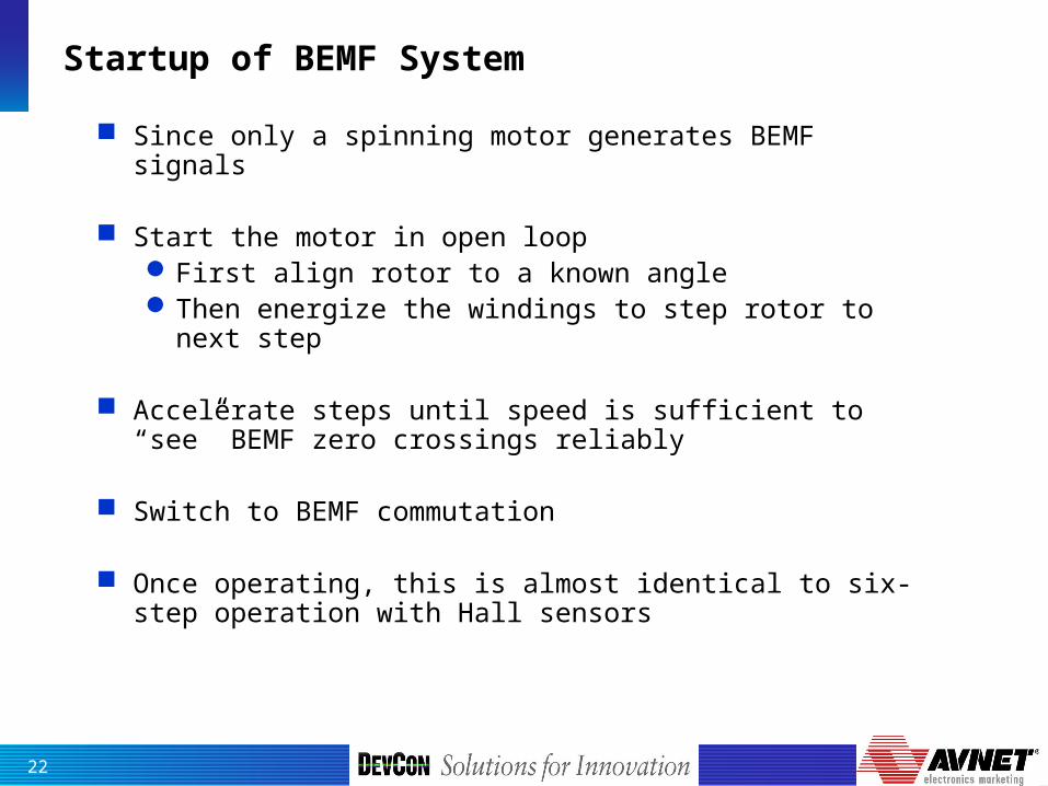
Startup of BEMF System
Since only a spinning motor generates BEMF signals
Start the motor in open loopFirst align rotor to a known angleThen energize the windings to step rotor to next
step
Accelerate steps until speed is sufficient to “see” BEMF zero crossings reliably
Switch to BEMF commutation
Once operating, this is almost identical to six-step operation with Hall sensors
23
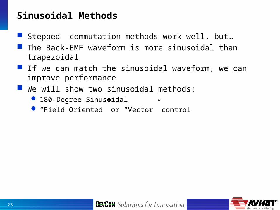
Sinusoidal Methods
Stepped commutation methods work well, but… The Back-EMF waveform is more sinusoidal than trapezoidal If we can match the sinusoidal waveform, we can improve
performance We will show two sinusoidal methods:
180-Degree Sinusoidal “Field Oriented” or “Vector” control

24
180° Sinusoidal Commutation
Modulates sine waves in all three windings Pros: No square edges
Lower Torque Ripple then six-step drive Lower audible noise
Higher efficiency and torque Stator angle is rotated smoothly rather
than in 60 degree jumps Each phase is utilized all of the time
Cons: Needs higher resolution feedback to
calculate sine waves with low distortion Needs more sophisticated processing to
calculate sine PWM values on the fly Bandwidth of currents are limited due to
motor impedance, this hurts high speed performance
25
*r
Speed Regulatorr
*qi
0* dirid PI
Regulator
iq PIRegulator d,q
to
,)(1 T
Motor Model Based Flux and
Position Observer
qi
di
*qU
*dU
*U
*U
Voltage Source3-phaseInverter
SINPWM
PWM1~6
toa, b, c
,
3-phasePMSM
r
tod,q
,
)(T
ai
bidi
qi
ii
a,b,c to ,
Speed Estimation
DC Bus
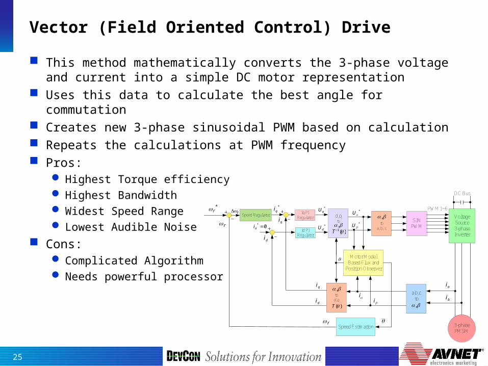
Vector (Field Oriented Control) Drive
This method mathematically converts the 3-phase voltage and current into a simple DC motor representation
Uses this data to calculate the best angle for commutation Creates new 3-phase sinusoidal PWM based on calculation Repeats the calculations at PWM frequency Pros:
Highest Torque efficiency Highest Bandwidth Widest Speed Range Lowest Audible Noise
Cons: Complicated Algorithm Needs powerful processor

26
BLDC Motor Speed Control
The goal of most Electronic Motor Control Systems is Speed Control
Speed Control systems are more or less complicated, depending on accuracy required
The simplest speed control is Open-Loop, that is, without speed feedback
In this configuration, a speed command is converted to a fixed voltage (PWM duty) which is sent to the motor
The motor may go the right speed, or it may not, it depends on the load
Without feedback, there is no way to tell internally what the real speed is and so may require outside adjustment
Speed Command
Pulse Width Modulator Transistors Motor Load
27
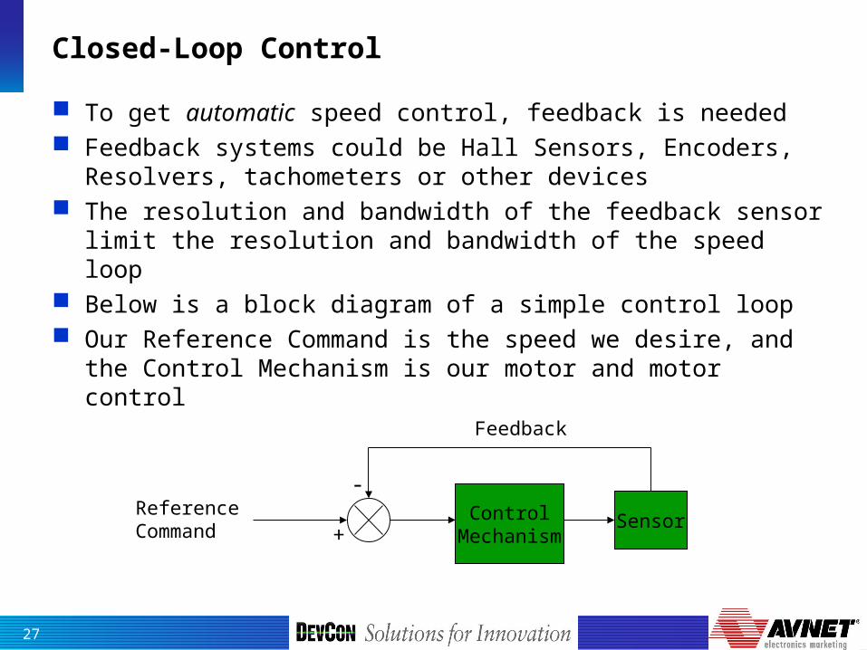
Closed-Loop Control
To get automatic speed control, feedback is needed Feedback systems could be Hall Sensors, Encoders,
Resolvers, tachometers or other devices The resolution and bandwidth of the feedback sensor limit
the resolution and bandwidth of the speed loop Below is a block diagram of a simple control loop Our Reference Command is the speed we desire, and the
Control Mechanism is our motor and motor control
ControlMechanism
SensorReference Command
Feedback
+
-
28
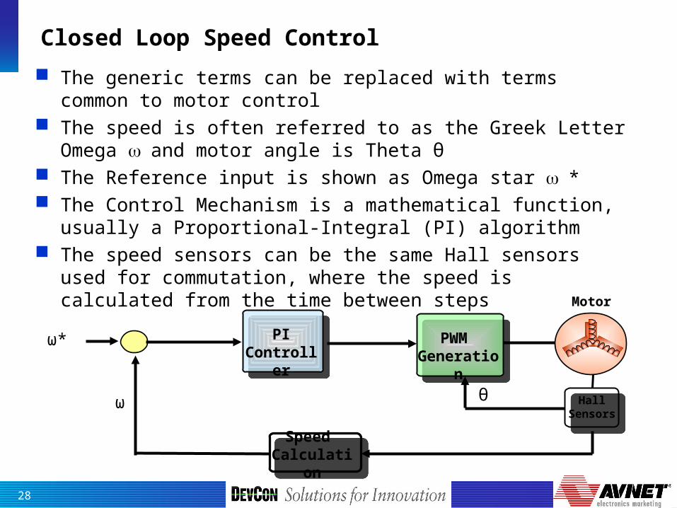
Closed Loop Speed Control
The generic terms can be replaced with terms common to motor control
The speed is often referred to as the Greek Letter Omega and motor angle is Theta θ
The Reference input is shown as Omega star * The Control Mechanism is a mathematical function, usually
a Proportional-Integral (PI) algorithm The speed sensors can be the same Hall sensors used for
commutation, where the speed is calculated from the time between steps
Hall Sensors
Speed Calculation
Motor
PWM Generation
PIController
ω*
ω θ

29
Closed Loop Speed Control
The way the loop works is to first measure the difference between the commanded speed and the actual speed
If the speed is to low, the PI controller increases the PWM duty which sends more voltage to the motor, correcting speed
If the speed to too high, the PI controller reduces the PWM, reducing the average voltage, so the motor slows down to the correct speed
The Proportional and Integral parameters have to be tuned to optimized the speed loop response-prevent speed oscillations
Hall Sensors
Speed Calculation
Motor
PWM Generation
PIController
ω*
ω θ

30
Motor Kit for Trapezoidal Control
BLDC Motor, Board, Software, Schematics, Tool and GUI
R8C/25
31
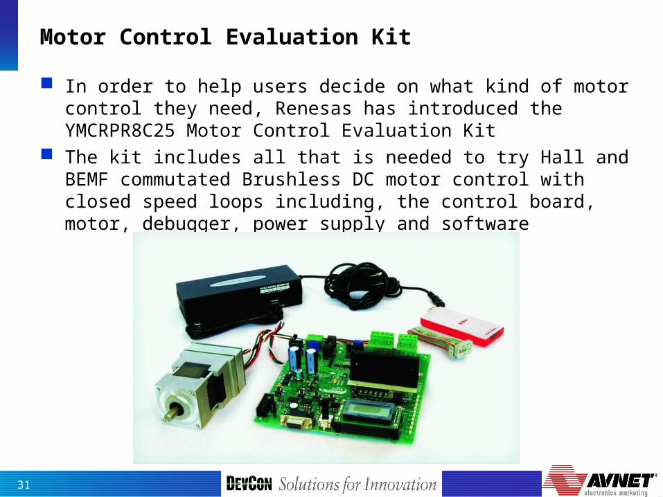
Motor Control Evaluation Kit
In order to help users decide on what kind of motor control they need, Renesas has introduced the YMCRPR8C25 Motor Control Evaluation Kit
The kit includes all that is needed to try Hall and BEMF commutated Brushless DC motor control with closed speed loops including, the control board, motor, debugger, power supply and software

32
YMCRPR8C25 Block Diagram
Power Supply &
Conditioning
R8C/25MCU
InternationalRectifier( I P M )
E8 Debug
I / F
4-LEDPWM / PWR
Status
LCD SegmentDisplay
M
Hall SensorInputs
Push-ButtonSwitch
R8C25 MCRP Kit
24v DCSupply
Jumper-1
BLDC Motor
VBUS
ShuntCurrent
Speed Control 6-PWM
RS232I/F
Shutdown
TP-1
TP-2
TP-3TP-4 CN-2
CN-1
CN-3
CN-4
TP-5
OP-AMP(Signal Conditioning)
Comparators( Back-EMF)
33
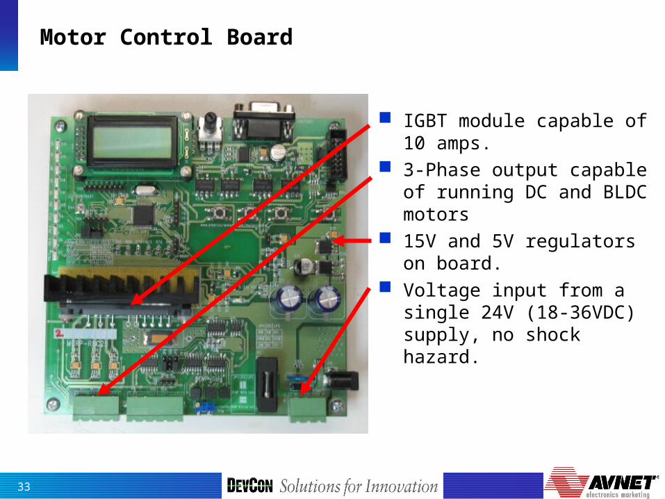
Motor Control Board
IGBT module capable of 10 amps.
3-Phase output capable of running DC and BLDC motors
15V and 5V regulators on board.
Voltage input from a single 24V (18-36VDC) supply, no shock hazard.

34
Board User Interface
Large potentiometer for speed control setting
2x8 LCD display with contrast pot for monitoring speed, current, etc.
Four push-buttons Bus voltage monitoring
to MCU Current monitoring to
the module for automatic protection

35
Commutation Options
Back-EMF detection comparators
Jumper selection (no soldering) between Hall and BEMF modes
Input connector for Hall signals from motor

36
Debugging Capabilities
Optically Isolated RS-232 communication
Optically Isolated E8(a) connector
Prototyping areas (under LCD)
LED’s for monitoring PWM lines, and GPIO
Abundant test points

37
Motor Control Graphical User Interface
Stop
Target Speed Actual SpeedSpeed Slider
Motor Current
System Status
38
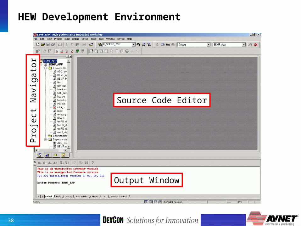
HEW Development Environment
Source Code Editor
Output Window
Pro
ject
Na
vig
ato
r
39
Summary
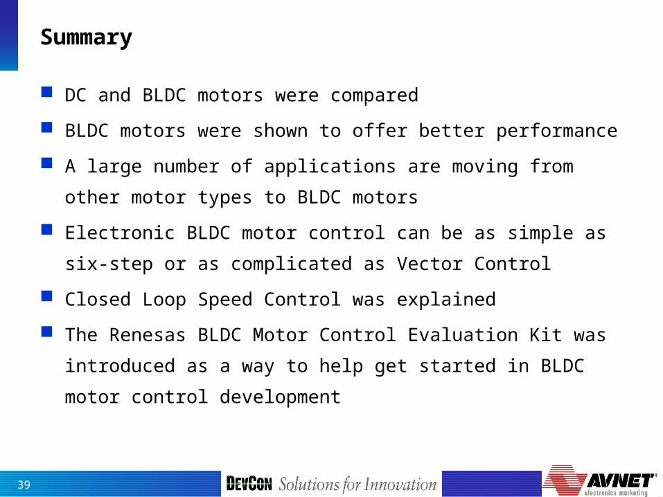
DC and BLDC motors were compared
BLDC motors were shown to offer better performance
A large number of applications are moving from other motor
types to BLDC motors
Electronic BLDC motor control can be as simple as six-step
or as complicated as Vector Control
Closed Loop Speed Control was explained
The Renesas BLDC Motor Control Evaluation Kit was
introduced as a way to help get started in BLDC motor
control development

40
Questions?

41
Appendix
42
WiFiSH, RX, R8C
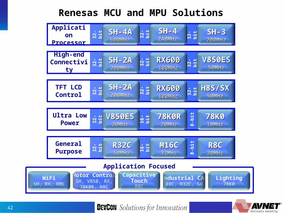
High-end Connectivity
V850ESV850ES50MHz50MHz
SH-2ASH-2A200MHz200MHz
Ultra Low Power
78K078K010MHz10MHz
78K0R78K0R20MHz20MHz
V850ESV850ES20MHz20MHz
R8CR8C20MHz20MHz
M16CM16C32MHz32MHz
R32CR32C50MHz50MHz
Application Focused Solutions
TFT LCD Control
H8S/SXH8S/SX50MHz50MHz
SH-2ASH-2A200MHz200MHz
General Purpose 8
-bit
16
-bit
32
-bit
Renesas MCU and MPU Solutions
32
-bit
32
-bit
32
-bit
8-b
it
16
-bit
Application Processor
SH-3SH-3200MHz200MHz
SH-4SH-4240MHz240MHz
SH-4ASH-4A600MHz600MHz3
2-b
it
32
-bit
32
-bit
32
-bit
32
-bit
32
-bit
32
-bit
Motor ControlSH, V850, RX,78K0R, R8C
Capacitive Touch
R8C
Industrial CANR8C, R32C, SH
Lighting78K0
RX600RX600100MHz100MHz
RX600RX600100MHz100MHz
43
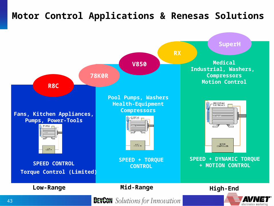
Motor Control Applications & Renesas Solutions
High-EndLow-Range Mid-Range
SPEED + TORQUECONTROLSPEED CONTROL
SPEED + DYNAMIC TORQUE+ MOTION CONTROL
Fans, Kitchen Appliances,Pumps, Power-Tools
Pool Pumps, WashersHealth-Equipment
Compressors
MedicalIndustrial, Washers,
CompressorsMotion Control
Torque Control (Limited)
R8C
78K0R
SuperH
V850
RX
44
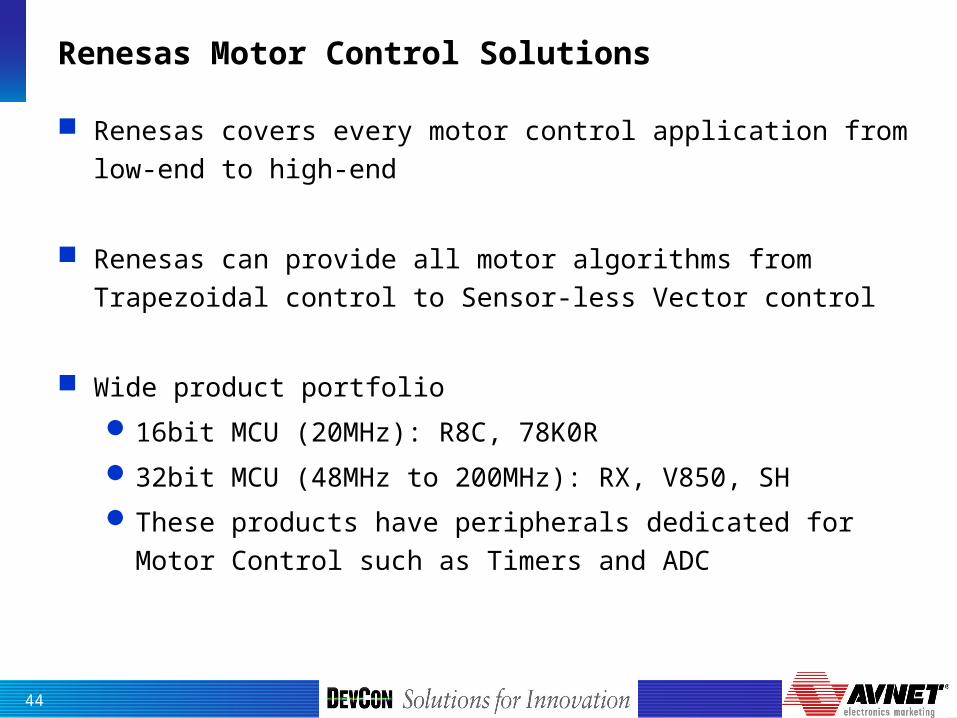
Renesas Motor Control Solutions
Renesas covers every motor control application from low-end to high-end
Renesas can provide all motor algorithms from Trapezoidal control to Sensor-less Vector control
Wide product portfolio
16bit MCU (20MHz): R8C, 78K0R
32bit MCU (48MHz to 200MHz): RX, V850, SH
These products have peripherals dedicated for Motor Control such as Timers and ADC
45
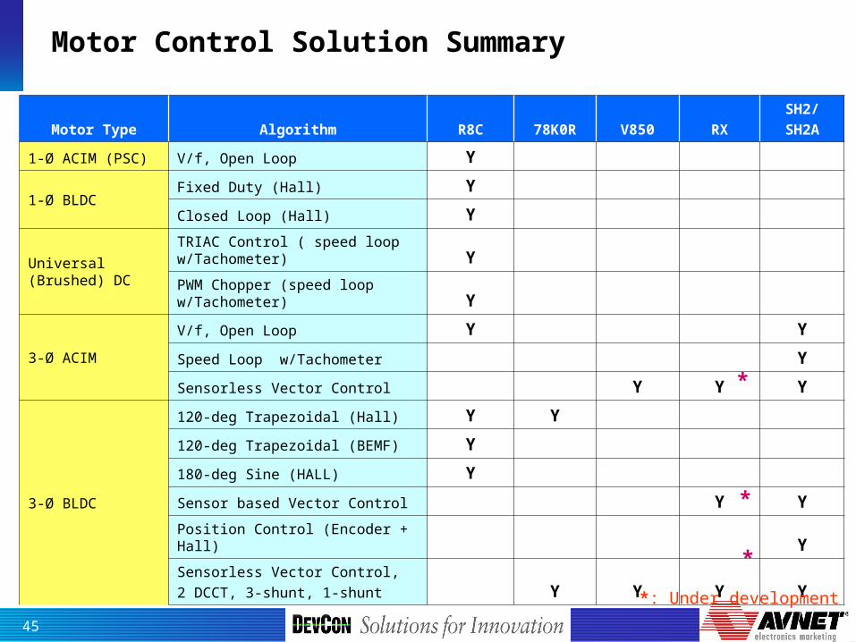
Motor Control Solution Summary
Motor Type Algorithm R8C 78K0R V850 RXSH2/SH2A
1-Ø ACIM (PSC) V/f, Open Loop Y
1-Ø BLDCFixed Duty (Hall) Y
Closed Loop (Hall) Y
Universal (Brushed) DC
TRIAC Control ( speed loop w/Tachometer) Y
PWM Chopper (speed loop w/Tachometer) Y
3-Ø ACIM
V/f, Open Loop Y Y
Speed Loop w/Tachometer Y
Sensorless Vector Control Y Y Y
3-Ø BLDC
120-deg Trapezoidal (Hall) Y Y
120-deg Trapezoidal (BEMF) Y
180-deg Sine (HALL) Y
Sensor based Vector Control Y Y
Position Control (Encoder + Hall) Y
Sensorless Vector Control, 2 DCCT, 3-shunt, 1-shunt Y Y Y Y
*
*
*
*: Under development
