idcs 100 installation guide - Укрсервис: оборудование...
TRANSCRIPT

iDCS 100
Installation GuideInstallation GuideInstallation GuideInstallation Guide

iii
Copyright © Samsung Electronics Co., Ltd. 2003
All rights reserved. Samsung, the Samsung logo, Samsung iDCS 100 are registered trademarks. All otherproduct names are used for identification only and may be trademarks and/or registered trademarks of theirrespective companies. Product specifications subject to change without notice.
No part of this manual may be reproduced in any form or by any means – graphic, electronic or mechanical,including recording, taping, photocopying or information retrieval systems – without express writtenpermission of the publisher of this material.

iv
Preface
About This ManualiDCS 100, Digital Communication System, is a digital telephone system designed for small to medium–sizedbusinesses. This manual provides the information about installation of the Samsung iDCS 100, DigitalCommunication System, including information about connecting the equipments.
This guide consists of following 9 chapters. Find and read necessary chapters.
! Site Requirements
! Installing Basic KSU and Expansion Cabinet
! Installing Printed Circuit Cards
! Power Up Procedures
! Connecting CO Circuit
! Connecting Station Equipment
! Connecting Optional Equipment
! Installing Keyset Daughter Boards
! Changing Software
Supporting DocumentsFurther detail on all of the aspects covered in this manual is included in the system General Description andProgramming guide. The iDCS 100 system provides the following manuals for more information:
! General Description Guide
This manual provides an overview of the Samsung iDCS 100, Digital Communication System, includingsystem structure and hardware, features and facilities and specifications.
! Installation Guide
This manual provides the information about installation of the Samsung iDCS 100, DigitalCommunication System, including information about connecting the equipments.
! Programming Guide
iDCS 100 system provides MMC(Man Machine Communication) program. Users can configure thesystem using the MMC program at the digital telephone.This manual describes how to use the MMC program.

v
Table of Contents
CHAPTER 1 SITE REQUIREMENTS ........................................................................................................................1-1
C H A P T E R 2 IN S TA L L IN G B A S IC K S U A N D E X PA N S IO N C A B IN E T ..............................................................................2-1
SYSTEM CAPACITY............................................................................................................................................................2-1UNPACKING AND INSPECTION............................................................................................................................................2-1BASIC KSU INSTALLATION................................................................................................................................................2-2EXPANSION KSU INSTALLATION........................................................................................................................................2-3RGU(RING GENERATOR UNIT) INSTALLATION ...................................................................................................................2-7GROUNDING .....................................................................................................................................................................2-8MDF CABLING .................................................................................................................................................................2-8BATTERY FOR POWER FAILURE..........................................................................................................................................2-9
CHAPTER 3 INSTALLING PRINTED CIRCUIT CARDS .......................................................................................3-1
3TRK CARD.....................................................................................................................................................................3-16 TRK CARD....................................................................................................................................................................3-36 MWSLI CARD...............................................................................................................................................................3-38 SLI CARD......................................................................................................................................................................3-42 SLI CARD......................................................................................................................................................................3-48 DLI CARD .....................................................................................................................................................................3-5MISC 1 CARD ..................................................................................................................................................................3-6MISC 2 CARD ..................................................................................................................................................................3-6TEPRI OR PRI CARD........................................................................................................................................................3-74BRI(4S0T0)/2BRI(2S0T0) CARD ...................................................................................................................................3-9PLL CARD .....................................................................................................................................................................3-11MODEM CARD..............................................................................................................................................................3-12MEM CARD (MEM3 OR MEM4)....................................................................................................................................3-12SVMi-4 CARD ..............................................................................................................................................................3-13SVMi-8 CARD ..............................................................................................................................................................3-14ITM3 CARD ...................................................................................................................................................................3-15
CHAPTER 4 POWER UP PROCEDURES.................................................................................................................4-1
CONNECT POWER TO THE SYSTEM.....................................................................................................................................4-1MEM CARD INDICATIONS .................................................................................................................................................4-1PCB VERIFICATION...........................................................................................................................................................4-2DEFAULT TRUNK AND STATION NUMBERING ......................................................................................................................4-3
CHAPTER 5 CONNECTING CO CIRCUIT ..............................................................................................................5-1
SAFETY PRECAUTION........................................................................................................................................................5-1LOOP START LINES............................................................................................................................................................5-2OFF PREMISED EXTENSION (OPX)....................................................................................................................................5-3ISDN CO LINES ...............................................................................................................................................................5-4
CHAPTER 6 CONNECTING STATION EQUIPMENT ............................................................................................6-1
SAFETY PRECAUTIONS ......................................................................................................................................................6-1IDCS 100 KEYSET............................................................................................................................................................6-2ADD-ON MODULE ............................................................................................................................................................6-4SINGLE LINE TELEPHONE ..................................................................................................................................................6-6DOOR PHONE AND DOOR LOCK RELEASE ..........................................................................................................................6-8ISDN TE (ISDN PHONE, G4 FAX, ETC) .........................................................................................................................6-10

vi
CHAPTER 7 CONNECTING OPTIONAL EQUIPMENT.........................................................................................7-1
MUSIC ON HOLD/BACK GROUND MUSIC ...........................................................................................................................7-1EXTERNAL PAGING ...........................................................................................................................................................7-2COMMON BELL.................................................................................................................................................................7-4RING OVER PAGE..............................................................................................................................................................7-5STATION MESSAGE DETAIL RECORDING (SMDR)...............................................................................................................7-5PC PROGRAMMING ...........................................................................................................................................................7-6REMOTE PROGRAMMING...................................................................................................................................................7-6POWER FAILURE TRANSFER (PFT).....................................................................................................................................7-7VOICE MAIL/AUTO ATTENDANT .......................................................................................................................................7-7
CHAPTER 8 ADDING A KEYSET DAUGHTER MODULE....................................................................................8-1
ADDING A DAUGHTER MODULE TO EURO KEYSET(FOR EUROPE).....................................................................................8-1KDB-S..........................................................................................................................................................................8-1KDB-D.........................................................................................................................................................................8-5Connecting to the KDB-D & KDB-S..............................................................................................................................8-5
ADDING A DAUGHTER MODULE TO IDCS SERIES KEYSET(FOR U.S) ..................................................................................8-6
CHAPTER 9 CHANGING SOFTWARE.....................................................................................................................9-1

vii
List of Figures
FIGURE 2-1 BASIC KSU (KEY SERVICE UNIT)........................................................................................................2-2FIGURE 2–2 BASIC KSU + EXPANSION A................................................................................................................2-3FIGURE 2–3 BASIC KSU + EXPANSION B................................................................................................................2-3FIGURE 2-4 RIGHT SIDE VIEW OF BASIC KSU ......................................................................................................2-4FIGURE 2-5 ASSEMBLE BETWEEN BASIC KSU & EXP.CABINET(1).......................................................................2-5FIGURE 2-6 ASSEMBLE BETWEEN BASIC KSU & EXP.CABINET(2).......................................................................2-5FIGURE 2-7 BOTTOM SIDE OF BASIC KSU.............................................................................................................2-6FIGURE 2-8 CABLING FOR MDF.............................................................................................................................2-6FIGURE 2-9 INSTALLATION OF RGU.......................................................................................................................2-7FIGURE 2-10 CABLING FOR BATTERY CONNECTION ...........................................................................................2-9
FIGURE 3-1 3TRK CARD AND 6TRK CARD .............................................................................................................3-1FIGURE 3-2 16MWSLI CARD....................................................................................................................................3-3FIGURE 3-3 8SLI CARD AND 2SLI CARD.................................................................................................................3-4FIGURE 3-4 8DLI CARD AND MISC1/ MISC2 CARD................................................................................................3-5FIGURE 3-5 TEPRI CARD.........................................................................................................................................3-8FIGURE 3-6 PRI CARD .............................................................................................................................................3-9FIGURE 3-7 LOCATION OF TERMINATION ON/OFF SWITCH .............................................................................3-10FIGURE 3-8 4BRI/2BRI CARD.................................................................................................................................3-10FIGURE 3-9 PLL CARD AND MODEM ................................................................................................................... 3-11FIGURE 3-10 MEM3 CARD ...............................................................................................................................3-12FIGURE 3-11 MEM4 CARD .....................................................................................................................................3-12FIGURE 3-12 SVMi-4 CARD....................................................................................................................................3-13FIGURE 3-13 SVMi-8 CARD....................................................................................................................................3-14FIGURE 3-14 ITM3 CARD.......................................................................................................................................3-16
FIGURE 5-1 MDF CONNECTIONS LOOP START LINE TO OPTION CARD.............................................................5-2FIGURE 5-2 MDF CONNECTIONS OFF PREMISE EXTENSION FROM 2 SLI CARD ..............................................5-3FIGURE 5-3 ISDN INTERFACE CONNECTION FOR PRI .........................................................................................5-4FIGURE 5-4 MDF CONNECTIONS FOR ISDN CO LINE TO CARD (4BRI)...............................................................5-5FIGURE 5-5 MDF CONNECTIONS FOR ISDN CO LINE TO CARD (2BRI)...............................................................5-6
FIGURE 6-1 MDF CONNECTIONS DIGITAL KEYSET TO BASIC KSU P1................................................................6-2FIGURE 6-2 MDF CONNECTIONS DIGITAL KEYSET TO OPTION CARD...............................................................6-3FIGURE 6-3 MDF CONNECTIONS AOM TO BASIC KSU P1....................................................................................6-4FIGURE 6-4 MDF CONNECTIONS AOM TO OPTION CARD...................................................................................6-5FIGURE 6-5 MDF CONNECTIONS SINGLE LINE TELEPHONE TO 2 SLI CARD ....................................................6-6FIGURE 6-6 MDF CONNECTIONS SLT TO OPTION CARD .....................................................................................6-7FIGURE 6-7 MDF CONNECTIONS DOOR PHONE TO BASIC KSU P1 ....................................................................6-8FIGURE 6-8 MDF CONNECTIONS DOOR PHONE TO DOOR CARD ......................................................................6-9FIGURE 6-9 MDF CONNECTIONS ISDN TEs TO 2BRI/4BRI CARD.......................................................................6-10
FIGURE 7-1 MDF CONNECTIONS CONNECTING MOH SOURCE TO KSU............................................................7-1FIGURE 7-2 MDF CONNECTIONS CONNECTING PAGE AMPLIFIER TO KSU ......................................................7-2FIGURE 7-3 MDF CONNECTIONS CONNECTING PAGE AMPLIFIER TO KSU ......................................................7-3FIGURE 7-4 MDF CONNECTIONS COMMON BELL CONTACTS ............................................................................7-4FIGURE 7-5 PIN CONNECTIONS FOR MISC CARD TO PRINTER...........................................................................7-5FIGURE 7-6 PIN CONNECTIONS FOR MISC CARD TO PERSONAL COMPUTER ..................................................7-6FIGURE 7-7 PIN CONNECTIONS FOR MISC CARD TO MODEM............................................................................7-6FIGURE 7-8 MDF CONNECTIONS VOICE MAIL TO SLI CARD...............................................................................7-7
FIGURE 8-1 BOTTOM KTS (Euro KTS) .....................................................................................................................8-1FIGURE 8-2 BOTTOM OF KTS (Euro KTS) ...............................................................................................................8-1FIGURE 8-3 BOTTOM OF KTS (Euro KTS) ...............................................................................................................8-2FIGURE 8-4 BOTTOM OF KTS (Euro KTS) ...............................................................................................................8-2FIGURE 8-5 BOTTOM OF KTS (Euro KTS) ...............................................................................................................8-3FIGURE 8-6 CONNECTING FOR MDF (Euro KTS)...................................................................................................8-3FIGURE 8-7 CONNECTING A STATION DEVICE TO A KDB VIA THE MAIN DISTRIBUTIONFRAME (Euro KTS)..8-4FIGURE 8-8 CONNECTING A SINGLELINE TELEPHONE TO A KDB-S (Euro KTS)................................................8-5

viii
FIGURE 8-9 CONNECTING A KEYSET TO A KDB-D (Euro KTS) .............................................................................8-5

1-1
Chapter 1 Site RequirementsWhen planning the installation of the iDCS 100, choose a site that meets the following requirements:
! Select a location for the key service unit (KSU) that has enough space for easy installation and hasadequate lighting (See Figure 2-1).
! Select a location that will minimize cable lengths. See the CABLE REQUIREMENTS table below.
! The equipment must not be exposed to direct sunlight, corrosive fumes, dust, constant vibration orstrong magnetic fields such as those generated by motors and copy machines.
! A direct commercial AC power outlet is required. Do not use extension cords.Preferably, a dedicated circuit must be used to minimize the risk of other electrical equipment beingconnected that could adversely affect system operation.
! Ensure that all wires and cable going to and coming from the KSU are properly routed. Do notcross fluorescent lights or run parallel with AC wires.
! The equipment must be located in an environment that will maintain a temperature range of32°~104°F (0°~40°C) and a humidity range of 10%~90% non-condensing.
! Allow at least 15cm clearance on both sides and 15cm clearance on top of the KSU to ensure properventilation.
! Do not install in close proximity to a fire sprinkler head or other sources of water.
Meeting these requirements will help to ensure proper performance and greater life expectancy of thesystem.
CABLE REQUIREMENTS
EQUIPMENT CABLE AWG MAX FEET MAX METERS
DIGITAL KEYSETS 1PR. TWISTED 24 1300 400
ADD-ON MODULES 1PR. TWISTED 24 1300 400
SINGLE LINE STATION 1PR. TWISTED 24 3000 1 KM
DOOR PHONE 2PR. TWISTED 24 330* 100
* This is the maximum distance a door phone can be from the DPIM. The DPIM can be a maximum of270 meters cable from the KSU.

1-2 Chapter 1Site Requirements
ELECTRICAL SPECIFICATIONS
Item Specification
AC INPUT 220~240VAC, 50Hz, 3.0A
POWER CONSUMPTION(MAX)
140 WATTS (MAX)
DC OUTPUT
FUSE RATING 2AMP+5 VOLTS 4.0 AMPS MAX- 55 VOLTS 1.7 AMPS MAX (for SLT/KTS Feeding voltage)- 54 VOLTS 0.4 AMPS MAX (for Battery charge)
DIMENSION AND WEIGHTS
Item Height (mm) Width(mm) Depth(mm) Weight(kg)
Basic Cabinet 464 365 148 7.5
Expansion Cabinet 484 467 148 12.5
Digital Keyset 108 213 229 1.2
Add-On Module 108 108 229 0.5
Door Phone 127 99 32 0.2
ENVIRONMENTAL LIMIT
Item Specification
Operating Temperature 0 ~ 40 °C
Storage Temperature - 10.5 ~ 70 °C

2-1
Chapter 2 Installing Basic KSU and ExpansionCabinet
System CapacityiDCS 100 system can have up to 48 stations if SVMi-8 is not used, and can have up to 40 stations if SVMi-8 isused. There is no limit in the analog C.O. line, and ISDN C.O line if any slot is available and PRI(TEPRI) orSVMi-8 can be adopted in the DCS slot on the EXP cabinet of iDCS 100. Some configuration examples arebelow.
! In this table, 4BRI (4S0T0) is used as digital trunk.
! 4BRI (4S0T0) card can be used as ISDN NT. Each port can have up to 8 ISDN TEs, but powerconsumption of each port is limited to 4 WATT.
! Only one ITM3 card can be equipped into the basic cabinet slots per system.
Combination of BoardsLoop Start
Trunk/BRI I/FKey sets
KDB-D/KDB-S
Max Capacity(Including KDB line)
Basic 0 8 8 0 * 8 (16)
Basic+3TRK 3 8 8 3 * 8 (16)
Basic+4BRI(4S0T0) 4(8CH) 8 8 8 * 8 (16)
Basic +4BRI(4S0T0)+8DLI * 2 4(8CH) 24 8 8 * 24 (32)
Basic +3TRK * 2 + 8DLI 6 16 8 6 * 16 (24)
Basic(4BRI (4S0T0) + 8DLI * 2)+EXP(4BRI (4S0T0)+8DLI * 2) 8(16CH) 40 8 16 * 40(48)
Basic(6TRK+8DLI* 2)+EXP(3TRK *2 +8DLI) 12 32 8 12 * 32(40)
Basic Rack Plus Expansion Cabinet
Unpacking and InspectionAfter unpacking the KSU, inspect for signs of physical damage. If any damage is detected, do not attempt toinstall. Contact Samsung Technical Support Department.
Check to see that Basic KSU carton includes the following items.
! Basic Key Service Unit (KSU) ! Spare Parts Ass’y
Check to see that Expansion KSU carton includes the following items.
! Expansion Key Service Unit(KSU) ! Spare Parts Ass’y
Basic Cabinet

2-2 Chapter 2Installing Basic KSU and Expansion Cabinet
MountingHole
MountingHole
iDCS 100
Basic KSU InstallationBasic KSU is accommodated in a metal cabinet which is wall mounted. In case of wall mounted, the KSUshould be mounted on a polywood back at least 5/8" thick. Attach a mounting screw to the back board.Next hang the KSU on the screws and screw it to the back board with the remaining two screws. Tighten allfour screws to secure KSU in place. (See Figure 2-1)
FIGURE 2-1 BASIC KSU (KEY SERVICE UNIT)

2-3
2SLI
Ringer
CHAMP connector
P1
P2CHAMP connector
P5
P4
PLL
SLOT1
SLOT2
SLOT3
MEM
Power Supply
MISC
SLOT4
SLOT5
SLOT6
DCSPRI
Expansion KSU InstallationExpansion KSU is simply attached to basic KSU with the following procedure.This manual instanced the Expansion cabinet A as the installation figures. The installation procedure ofExpansion Cabinet A is same with Expansion Cabinet B.
FIGURE 2–2 BASIC KSU + EXPANSION A
FIGURE 2–3 BASIC KSU + EXPANSION B

2-4 Chapter 2Installing Basic KSU and Expansion Cabinet
1. Switch OFF the power and remove the covers of both basic KSU and Expansion Cabinet A or B.2. Remove dummy tabs on the right side of the basic with appropriate tools for connection route.
A is for MDF cable and B is for signal and power cable. (See Figure 2-4)
FIGURE 2-4 RIGHT SIDE VIEW OF BASIC KSU
A
B

2-5
2SLI
CHAMP connector
P1
P2CHAMP connector
P2
SLOT1
SLOT1
SLOT1
MEM
Power Supply
MISC
SLOT4
SLOT5
SLOT6
DCSPRI
3. Move Expansion cabinet to basic cabinet and attach it via groove. (See Figure 2-5)
FIGURE 2-5 ASSEMBLE BETWEEN BASIC KSU & EXP.CABINET(1)
4. Fix Expansion cabinet with offered screw to back plane. (See Figure 2-6)
FIGURE 2-6 ASSEMBLE BETWEEN BASIC KSU & EXP.CABINET(2)

2-6 Chapter 2Installing Basic KSU and Expansion Cabinet
Ringer
2SLI
CHAMP connectorCHAMP connector
P5
SLOT1
SLOT2
SLOT3
MEM
Power Supply
MISC
SLOT4
SLOT5
SLOT6
DCSPRI
P1
P2
5. Connect Exp KSU to basic with flat cable and 2 wires. (See Figure 2-6)
6. Insert new optional card.
7. Connect MDF cable through appropriate path. (See figure 2-7 & 2-8)
FIGURE 2-7 BOTTOM SIDE OF BASIC KSU
FIGURE 2-8 CABLING FOR MDF
8. Now cover the cabinets and switch ON the power.

2-7
Ringer
2SLI
CHAMP connector
P1
P2
SLOT1
SLOT2
SLOT
3 MEM
Power Supply
MISC
RGU(Ring Generator Unit) InstallationThe RGU can be mounted in the Basic KSU by offered screw.The Cable Ass’y(4Pin) of RGU should be connected to connector P11 of 008 Base board. (See Figure 2-9)
FIGURE 2-9 INSTALLATION OF RGU

2-8 Chapter 2Installing Basic KSU and Expansion Cabinet
GroundingiDCS 100 comes equipped ready to use with a third wire AC ground provided through the power cord. Thisthird ground will be adequate for most application. However, if it is suspected that there is a problem withthe ground provided at AC outlet or local codes require a solid earth ground to be connected to the KSU, theexisting third wire ground must be disconnected before power is applied. The existing third wire ground isdisconnected by removing the holding screw and tapping and storing the wire. After this wire has beendisconnected, the grounding lug on the PSU(Power Supply Unit) must be connected to a ground rod ormetal cold water pipe using #A10 AWG solid copper wire.
Failure to provide an adequate ground may cause intermittent problems or even circuit card failure.
WARNING: Unplug the power cord from the AC outlet before attempting to connect the ground.Hazardous voltage may cause death or injury. Observe extreme caution when working with ACpower. Remove champ connectors.
MDF CablingAll connection to the iDCS 100 system are made by way of a customer-provided main distribution frame(MDF). The KSU and expansion kit are each connected to the MDF using a 25 pair female amphenol-typecable(with the exception of the TEPRI, ITM3 cards). These cables can be routed into the KSU cabinet frombelow. (See Figure 2-7 & 2-8)
Use one pair twisted wire to cross-connect stations or lines to their associated port.

2-9
Ringer
2SLI
CHAMP connector
P1
P2
CHAMP connector
SLOT1
SLOT2
SLOT3
MEM
Power Supply
MISC
SLOT4
SLOT5
SLOT6
DCSPRI
BATTERY
RED
+
BLACK
P5
Battery for Power FailureBattery Selection
If you want to use iDCS 100 system during power failure, install appropriate batteries. If you adopt batterywhose capacity is too large, iDCS 100 system may be shut down, and if too small, iDCS 100 system may notoperate during power failure. In any case, use battery connection cable offered with iDCS 100.
Installation ProcedureFeed battery cable through MDF cable path; connect cable to battery, RED to positive(+), BLACK tonegative(-), then insert housing connector to head pin in power supply. (See Figure 2-10)
FIGURE 2-10 CABLING FOR BATTERY CONNECTION

2-10 Chapter 2Installing Basic KSU and Expansion Cabinet
Recommanded Battery Specification
Charge Discharge
Minimum Load Current (A) 0 0.05
Maximum Load Current (A) 0.4 0.7
Norminal Load Current (A) 0.1 0.5
Norminal Output Voltage (V) 54 49
! Max KTS current consumption : 30mA
CAUTION: Be sure the polarity is observed. Equipment damage will result if polarity is reversed.Do not connect external AC or DC power to the system shocked by electric power.

3-1
Chapter 3 Installing Printed Circuit CardsUnpack and inspect each card before installing. Check for signs of physical damage. If any damage isdetected, do not attempt to install. Contact Samsung Technical Support immediately.
3TRK Card3 loop start trunk Ports and 2 PFT Ports for Power failure transfer. (See Figure 3-1)This card has no selectable option. Insert the 3 TRK card into the appropriate slot. Push firmly in the middleof both card ejectors to ensure that it is fully inserted into the back plane connector.

3-2 Chapter 3Installing Printed Circuit Cards
FIGURE 3-1 3TRK CARD AND 6TRK CARD

3-3
6 TRK Card6 loop start trunk ports and 2 PFT ports for power failure transfer.(See Figure 3-1)This card has no selectable option. Insert the 6 TRK card into the appropriate slot. Push firmly in the middleof both card ejectors to ensure that it is fully inserted into the back plane connector.
6 MWSLI Card
FIGURE 3-2 16MWSLI CARD

3-4 Chapter 3Installing Printed Circuit Cards
DIP
8SLI
DIP
U1
2
80
75
65
70
C1
14
C1
08
Q5
8
ZD
17
T9
C1
12
C1
07
D4
4
52
52
0
50
1JP
1
Q6
1Q5
9
U1
4C
11
7
P3
C116
C120
R1
84
C9
0
C9
5
C9
3
P1
10
15
5V
A8
VA
6V
A4
VA
3V
A1
VA
2V
A5
VA
7
26
1
C7
1
U1
1
U1
0U
6
C6
8
C65
C61
U2
25
40
45
50
U9
C8
4
U5
U8
HY
B4
HY
B3
U4
Q4
C4
0
R1
5R
32
R1
8R
56
C6
3
C5
4R
55
C5
5C2
3
C6
2
C2
2
C2
9C
36
C2
7
Q1
2Q
14
Q1
3Q
11
Q9
Q1
0
Q1
C3
5C
34
C5
7
C1
7
T1
Q2
T2
Q3
T3
Q4
T4
Q5
T5
Q1
5
Q6
T6
Q7
T7
C3
3C
25
C2
6C
28
C2
1
C3
7
C5
1
C2
0C
19
C1
8
C5
2C
53
C4
5
P2
C4
C4
4C
3C
43
C2
C4
2C
1C
5
20
10
11
5
C6
C4
6
HY
B2
HY
B1
C4
7C
7C
48
C5
0
C5
1
C4
9
C4
1
C5
9
C5
0
C5
8
C3
8
C3
0R
31
R1
4R
13
RL5
RL6
RL8
RL7
RL4
RL3
RL2
RL1
R1
1R
10
R9
R4
9R
52
R5
1
R2
6R
25
R1
2R
53
R5
4
R3
0R
29
R2
8R
27
C3
9
C6
4
C5
6
C3
1C
24
T8
C3
2
Q8
Q1
66
0
55
35
30
B1
U3
U7
C7
5
C8
C7
4
C7
8
R2
11
L1
U1
5C
10
5
U1
3
U1
201 5 10
15
MA
DE IN
K
OR
EA
C
OM
PA
CT II [
8SLI ]
C/S
BA
R
CO
DE
8 SLI CardWhich has 8 subscriber line ports (See Figure 3-3)This card has no selectable option. Insert the 8 SLI card into the appropriate slot. Push firmly in the middleof both card ejectors to ensure that it is fully inserted into the back plane connector.
FIGURE 3-3 8SLI CARD AND 2SLI CARD
2 SLI Cardwhich has 2 subscriber line port (See Figure 3-3)This card has no selectable option. Insert the card into the 2 SLI slot. Push firmly in the middle of both cardejectors to ensure that it is fully inserted into the back plane connector.
U2
02
BA
R C
OD
E
[ 2SLI ]
650 2
40022D
BA
A C
/S P
CS;
MA
DE IN
K
OR
EA
U1
02
1 5 10
15 20
C1
T2
T1
C103
HY
B3
HY
B2
HY
B1
K2
K1
C104
C203
C204
1
11
C3
C5
30
64
60
55
50
45
40
35
25
20
15
10
ARS203
SBT4
SBT3
ARS103
ARS201
ARS202
ARS101
ARS102
SBT2
SBT1
5
C1
01
RW
3
RW
2
C2
02
C2
01
Q1
Q2
RW
1
C1
02
1
HY
B4

3-5
P1
U12
U22
U21
U23
C8
C25
RLY
1R
LY
3R
LY
2
C33
C34
C32
H2
P2
TN
R3
TN
R1
TN
R2 H
17
DSS1
U20
B5
B2
Y2
B3
TP1
B4
U19
U15
U31
58
C27
74H
C08
74H
C541
74H
C245
74H
C32
74H
C04
68
EC
00
074H
C04
74H
C174
74H
C08
74H
C125
74H
C139
U11
20
10
U29
U28
U27
U17
U16
U4
U3
BA
RH
1
U9
U14
U8
U2
MIS
C
27C
512
27C
4001
U30
KM
681000
KM
681000
KM
681000
KM
681000
KM
681000
KM
681000
KM
681000
KM
681000
14
PC
M2
P5
H4
H20
BA
R
H21
U25
U24U13U1 U7
MISC2
H16
H15
H7
H23
H6
U26
STL7053
STC
9604
ST
L7
06
5
U10H
24
H12
P3
30
20
40
15
20
20
10
150
110
120
130
140
30
30
33
140
40
5
50
50
60
40
5
35
30
60
60
50
80
180
120
130
160
150
140
H11
16.3
8M
Hz
80
100
110
160
D1
PC
M1
14
P4
BA
T1
H5
B1
170
200
190
H8
70
60
80
70
100
90
45
55
65
50
10
25
15
20
10
10
30
25
C29
U18
64
32
14
D7
MC
145407
TP3057
MC
34072D
MC
145407
MC
68681
3.6
864M
Hz
H3
Y1
159
48
37
26
159
48
37
26
40
30
C8
C26
T1
T2
C19
H9 739
29
40
17
15
103
5
5
9 U5
DIP
8 DLI CardWhich has 8 digital phone ports. (See Figure 3-4)This card has no selectable option. Insert the 8 DLI card into the appropriate slot. Push firmly in the middleof both card ejectors to ensure that it is fully inserted into the back plane connector.
FIGURE 3-4 8DLI CARD AND MISC1/ MISC2 CARD

3-6 Chapter 3Installing Printed Circuit Cards
MISC 1 CardWhich has many miscellaneous function DTMF receiver(4ch), RS232C, BGM, PAGE, COMMON PURPOSERELAY(3port), MODEM(option) (See Figure 3-4)Select appropriate type of MISC card for your system. If you choose MISC 1 card then insert the MISC 1 cardinto the MISC slot and PUSH firmly in the middle of both card ejectors to ensure that it is fully inserted intothe back plane connector.
MISC 2 CardWhich has many miscellaneous function DTMF receiver (4ch), RS232C, BGM, PAGE, COMMON PURPOSERELAY (3port), AA, MODEM (option) (See Figure 3-4)Select appropriate type of MISC card for the system. If you choose MISC 2 card then insert the MISC 2 cardinto the MISC slot and PUSH firmly in the middle of both card ejectors to ensure that it is fully inserted intothe back plane connector.

3-7
TEPRI or PRI CardWhich has 30 channel U interface ports.This card has no selectable options. Insert PRI into the last slot in the Expansion cabinet (type A or B).Firmly push in the middle of the card to ensure that it is fully inserted into the back plane connector. PRIcard needs PLL B'd installing first. Before installing PRI card, PLL B'd must be installed.The TEPRI card is installed in the DCS slot on expansion cabinet. The iDCS 100 supports either E1 or ISDNPRI service. The first four LEDs on the front of the card provide the status of the service (Sync, AIS, Loss andLayer 2 Active states). The second four LED’s on the front of the card display the type of service. There aretwo RJ45 modular jacks on the face of the card. The settings for E1 or PRI service are selected by a bank ofDIP switches as defined below (See Figure 3-5). Push firmly in the middle of both card ejectors on each cardto ensure that it is fully inserted into the back plane connector.
TEPRI CARD DIP SWITCH
Switch No. ON OFF
1 T1 E1
2 PRI T1
4 NETWORK USER
5,6,7 Not-used Not-used
8 Not-used
TEPRI LED DEFINITIONS
LED Name FunctionStatus
(Normal Status/Error Status)
SYN Synchronization Loss. Indicates wander or loss of framing. OFF/ON
LOS Loss of Signal. No PCM Clocking is being received. OFF/ON
AISAlarm Indicating Signal. Indicating that all one’s are beingreceived.
OFF/ON
L2 Layer 2 is active. PRI messaging is being received. OFF/ON
IPC IPC link set up. OFF/IPC link set up
CLK Card clock status.OFF/CARD is secondary sourceON card is primary source.
MODE LED’s TP1 & TP2 show the span type TP1, TP2
E1 mode OFF/OFF
E1 PRI mode OFF/ON
T1 mode ON/OFF
T1 PRI mode ON/ON

3-8 Chapter 3Installing Printed Circuit Cards
FIGURE 3-5 TEPRI CARD

3-9
FIGURE 3-6 PRI CARD
4BRI(4S0T0)/2BRI(2S0T0) CardThis card supports both of S and T reference points defined by ITU-T. You can select the S/T mode of eachport respectively by MMC. Insert the 4BRI (4S0T0) card or 2BRI(2S0T0) into the universal slot and pushfirmly in the middle of both card ejectors to ensure that it is fully inserted into the back plane connector.

3-10 Chapter 3Installing Printed Circuit Cards
BRI card needs PLL board. Before installing 4 BRI, 2BRI, PLL board must be installed. The BRI card isequipped with DIP switch controlled line termination registers.
FIGURE 3-7 LOCATION OF TERMINATION ON/OFF SWITCH
FIGURE 3-8 4BRI/2BRI CARD
Termination ON/OFF switches
PS2
PS1
B12
B14
B15
B16
B18
B19
B20
B21 AR16
AR15
AR13
AR11
AR12
R99
R98
AR14
R100PS4
C8
3
C8
1
10
20
P2
C8
2
K3
K4
C6
9
C8
4
25
25
30
20
T1
1 11
40
35
35
68
EC
00
0ST
L7
06
6
68
10
00
27
C2
00
1
(EV
EN
)
CO
MPA
CT II EU
4S0T0 R
EV
. 01
27
C2
00
16
81
00
0
H8
H1
0
H1
1
H1
4
H1
2
H1
3H
9H
7
U4
U5
U6
B3
Y2
U9
80
70
60
10
U22
20
30
H6
U13
B2
U17
U20
U25
U34
HR
S R
/A(F
)H
RS R
/A(F
)H
RS R
/A(F
)
P3
H1
H29
U15
H2
26
13
U14
74H
C74
74H
C174
74H
C244
74H
C174
74H
C139
74H
C163
74H
C04
74H
C32
74H
C245
74H
C541
74H
C32
74H
C32
74H
C74
74H
C09
74H
C0474H
C373
DS1
23
2S
74H
C04
BA
R C
OD
E
74H
C08
74H
C125
74H
C74
PEB
2054
PE
B2
07
5P
EB
20
84
74H
C163
74H
C08
74H
C74
1P1
14
U19
U33
U24
U18
U8
50
U7
U23
U26
115
5
10
1
6P4
50
25
20
10
5
26
U29
C86
C85
C87
U28
U35(3
37)
U30
U32
U31
100
H5
40
B5
B4
90
U2
U12
U11
U10
40
T4
U16
U1
B1
U3 20
20
15
10
T3
25
25
20
30
H3
Y1
10
10
U2
7(
33
7 )
10
U2
1
5
50
65
55
45
40
55
15
15
5
T2
K2
K1
C8
0C
78
H3
5H
30
H4
C7
7C
79
35
35
C6
C5
C4
C1
30
30
60
15
SW1
RW
1
RW2
B17
PS3
B13
B11
B9
B7
B6
B8
B10
R95
R97
R96
AR6
AR10
AR9
AR8
AR5
AR7
AR4
AR3
AR1
AR2
R94
R93
DIP

3-11
PLL CardThis card has no selectable option and this card is only used when TEPRI, PRI or BRI card is adopted. Pushfirmly in the middle of 14 pin female connector. (See Figure 3-9)
FIGURE 3-9 PLL CARD AND MODEM

3-12 Chapter 3Installing Printed Circuit Cards
MODEM CardThis card is option card of MISC 1 or MISC 2, iDCS 100 can adopt internal modem. Push firmly in themiddle of 14 pin female connector. (See Figure 3-9)
MEM Card (MEM3 or MEM4)Select the appropriate of MEM for the system. Make sure that back up switch is OFF position. Insert theMEM card in the KSU slot labeled MEM. Push in middle of the MEM card (MEM3 or MEM4) to ensure thatit is fully inserted into the back plane connector.
To prevent accidental damage to MEM card, the connector on the back plane is positioned to mate only withthe MEM card. Other interface cards will not mate with this connector and MEM card will not mate with anyother connector.
MEM3 card has EPROM memory to support new features Window PC-MMC, ITM3 & TEPRI cards. MEM4card with LAN interface module, no selectable options. The LAN module is required to expand the systemmemory, to provide SIO ports 1EA, and a 10/100 base T LAN interface processor. MEM4 card has Flashmemory to support new features Window PC-MMC, ITM3, TEPRI cards and Networking solution by TEPRI,Program/Database up/down-load by LAN interface. (See Figure 3-10 and Figure 3-11)
FIGURE 3-10 MEM3 CARD FIGURE 3-11 MEM4 CARD

3-13
SVMi-4 CARDThe SVMi-4 is a self contained plug in voice mail and auto attendant card for the iDCS 100. It is designed tomeet the demands of the sophisticated voice mail user without sacrificing simplicity.The SVMi-4 may act as an Auto Attendant system only, a Voice mail system only or both.Out of the box the SVMi-4 can handle 2 calls simultaneously. It can be easily upgraded to handle up to 4calls simultaneously.No external line or power connections are necessary, these are accomplished directly through the phonesystem.At this time of this writing the memory capacity is about 5 hours, although changes in technology will allowfor additional storage as time goes on. (See Figure 3-12)
FIGURE 3-12 SVMi-4 CARD

3-14 Chapter 3Installing Printed Circuit Cards
SVMi-8 CARDNOTE: Before installing this card it should be correctly configured with a hard disk drive and theappropriate number of voice processing modules. One additional Voice Processing Module can beadded.
The SVMi-8 card is installed in DCS slot on the expansion cabinet. Only one SVMi-8 can be installed in aniDCS 100 system and it counts as eight(8) stations of the power supply rating. Check that the cabinet powerswitch is in the OFF position. Next, position the SVMi-8 card in the grooves of the card guide and gentlyslide the card in until it makes contact with the connector. Press gently but firmly on the top and bottom ofthe front edge of the card until the card sits in its connector. Ensure that you have installed the correct powersupply. (See Figure 3-13)
FIGURE 3-13 SVMi-8 CARD
3-15
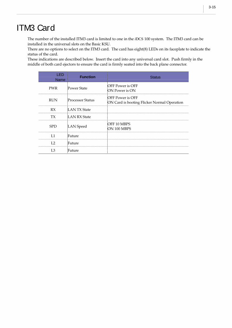
ITM3 CardThe number of the installed ITM3 card is limited to one in the iDCS 100 system. The ITM3 card can beinstalled in the universal slots on the Basic KSU.There are no options to select on the ITM3 card. The card has eight(8) LEDs on its faceplate to indicate thestatus of the card.These indications are described below. Insert the card into any universal card slot. Push firmly in themiddle of both card ejectors to ensure the card is firmly seated into the back plane connector.
LEDName
Function Status
PWR Power StateOFF Power is OFFON Power is ON
RUN Processor StatusOFF Power is OFFON Card is booting Flicker Normal Operation
RX LAN TX State
TX LAN RX State
SPD LAN SpeedOFF 10 MBPSON 100 MBPS
L1 Future
L2 Future
L3 Future
3-16 Chapter 3Installing Printed Circuit Cards
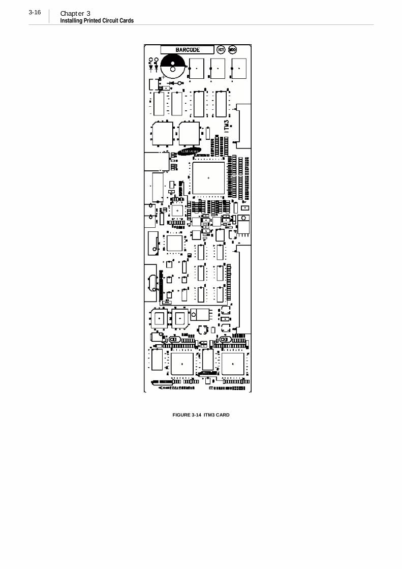
FIGURE 3-14 ITM3 CARD

3-17
(This page is left blank intentionally.)


4-1
Chapter 4 Power Up Procedures
Connect Power to The SystemDuring the initial installation, it is best to verify proper system operation before plugging in any amphenol-type cable to the MDF. If you have already plugged the cables in, unplug them.
Verify that the AC voltage at the dedicated electric outlet is in the range of 220-240 VAC.Make sure the AC power switch is in the OFF position and that MEM battery switch is OFF. Plug the KSUpower cord into the dedicated polarized AC outlet. Turn the AC power switch to the ON position. The ACand DC LED on the power supply will light steady to confirm the presence of power. If the PSU is operatedby external battery, AC LED is OFF and DC LED is ON. If the PSU AC LED fails to illuminate, unplug thesystem, remove the power supply and check the AC fuse located on the bottom.
If the fuse is good but the AC LED does not illuminate, check your AC outlet. Turn off the power switch;unplug all cards using card ejectors. Turn the system on. Check the AC LED again. If the problem iscorrected, you have a defective card. Test and remove the faulty card before continuing. If the AC LED stilldoes not light, unplugging the KSU and change power supplies. This in all probability will solve theproblem.If it does not, contact Samsung Technical Support.
MEM Card IndicationsHaving verified proper operation of the power supply, visually check the MEM card indications. The LED ofMEM3 or the LED4 of MEM4 should flicker rapidly indicating the main processor is functioning.The battery switch should now be turn ON. The system is equipped with a halt program.When this program is running, the LED is ON steady. The system must be reset to release the halt programand restore the system to manual operation. See MMC 810 for operation of the halt program.
MEM4 LED INDICATION
LED Status Indication
OFF The status of LAN transmit chip (LST972) is in abnormal1
ON The status of LAN transmit chip (LST972) is in normal
OFF LAN is linked2
ON LAN is not linked
OFF There is no LAN Rx data3
ON There is LAN Rx data
Flicker Slowly (500ms)RUN LED for main program.The main program is in normal operation status.
4Flicker Quickly (200ms)
RUN LED for main program.The main program is in booting operation status.
Flicker Slowly (500ms)RUN LED for main program.The LAN program is in normal operation status.
5Flicker Quickly (200ms)
RUN LED for main program.The LAN program is in booting operation status.

4-2 Chapter 4Power Up Procedures
PCB VerificationBefore connecting all MDF cable, plug in a test cable to the first DLI port. Connect a digital Telephone setand verify that it is working. Use maintenance program MMC 727 to verify the system version, and that allcards are recognized by the CPU. Process with rest of the installation.

4-3
Default Trunk and Station NumberingUpon initial power up, the CPU reads each slot for the existence of a card and identifies the type ofcard. It stores this as the default configuration.The system assigns trunk numbers beginning with 701 and continues. Station number are assigned in thesame manner. The lowest station is assigned station number 201 and continued Keyset daughter boards areassigned numbers beginning with 301 and continued.Default data assigns the 24 button keyset in the lowest port to the operator group and all trunks ring thatstation until default is changed. It is recommended that the operator station will default to a 24 button keyset as extension 201.Station and trunk numbers can be changed, rearranged and reassigned as needed using MMC 724.


5-1
Chapter 5 Connecting CO Circuit
Safety PrecautionTo limit the risk of personal injury, always follow these precautions before connecting CO circuit.
! Never install telephone wiring during a lightning storm.
! Never install telephone jacks in a wet location unless the jack is specially designed for wet location.
! Never touch uninsulated telephone wires or terminals unless the telephone line has beendisconnected at the network interface.
! Use caution when installing or modifying telephone lines.

5-2 Chapter 5Connecting TELCO Circuit
25 PAIR CABLE WITH FEMALE CONNECTOR TO EXPANSION P5
25 PAIR CABLE WITH FEMALE CONNECTOR TO BASIC P2
SLOT NO. PINNO
3TRK 4TRK 6TRK
25,50 C.O 1 C.O 1 C.O 1
24,49 C.O 2 C.O 2 C.O 2
23,48 C.O 3 C.O 3 C.O 3
22,47 N.C C.O 4 C.O 4
21,46 PFT1 N.C C.O 5
20,45 PFT2 N.C C.O 6
19,44 N.C N.C PFT1
SLOT 4
18,43 N.C N.C PFT2
17,42 C.O 4 C.O 5 C.O 7
16,41 C.O 5 C.O 6 C.O 8
15,40 C.O 6 C.O 7 C.O 9
14,39 N.C C.O 8 C.O 10
13,38 PFT3 N.C C.O 11
12,37 PFT4 N.C C.O 12
11,36 N.C N.C PFT3
SLOT 5
10,35 N.C N.C PFT4
9,34 C.O 7 C.O 9 C.O 13
8,33 C.O 8 C.O 10 C.O 14
7,32 C.O 9 C.O 11 C.O 15
6,31 N.C C.O 12 C.O 16
5,30 PFT5 N.C C.O 17
4,29 PFT6 C.O 18
3,28 N.C PFT5
SLOT 6
2,27 N.C PFT6
CO-PROVIDEDNETWORK ACCESS JACK
RJ 11CRJ 14CRJ 21X
Loop Start LinesThe iDCS 100 system requires MDF connection. All CO Line and Station is connected to the system withMDF. (See Figure 5-1)
SLOT NO. PIN NO. 3TRK 6TRK
25,50 C.O 1 C.O 1
24,49 C.O 2 C.O 2
23,48 C.O 3 C.O 3
22,47 N.C C.O 4
21,46 PFT1 C.O 5
20,45 PFT2 C.O 6
19,44 N.C PFT1
SLOT 1
18,43 N.C PFT2
17,42 C.O 4 C.O 7
16,41 C.O 5 C.O 8
15,40 C.O 6 C.O 9
14,39 N.C C.O 10
13,38 PFT3 C.O 11
12,37 PFT4 C.O 12
11,36 N.C PFT3
SLOT 2
10,35 N.C PFT4
9,34 C.O 7 C.O 13
8,33 C.O 8 C.O 14
7,32 C.O 9 C.O 15
6,31 N.C C.O 16
5,30 PFT5 C.O 17
4,29 PFT6 C.O 18
3,28 N.C PFT5
SLOT 3
2,27 N.C PFT6
FIGURE 5-1 MDF CONNECTIONS LOOP START LINE TO OPTION CARD
CONNECT TO ANY C.O CIRCUIT

5-3
25 PAIR CABLE WITH FEMALE CONNECTOR TO BASIC P1
CO-PROVIDEDNETWORK ACCESS JACK
RJ 11CRJ 14CRJ 21X
OFF Premised Extension (OPX)Using one pair twisted #24 AWG or #26 AWG wire, cross-connect each any 2SLI port to telephone companyOPX circuits. (See Figure 5-2)
FUNCTION CIRCUIT PIN COLOR
SLT TIPSLT RING
11641
Blue/yellowYellow/blue
SLT TIPSLT RING
21540
Grey/blackBlack/grey
FIGURE 5-2 MDF CONNECTIONS OFF PREMISE EXTENSION FROM 2 SLI CARD
Circuit on 2SLI card is specially designed to meet CO requirements for OPX use.These circuits are provided with the same over voltage and over current protection as CO Line circuit.
WARNING: Using long line Extensions on a 8SLI or KDB SLI may cause damage to your equipment.
CONNECT TO ANY CIRCUIT
ON 2 SLI CARD

5-4 Chapter 5Connecting TELCO Circuit
Ringer
2SLI
CHAMP connector
P1
P2
SLOT1
SLOT2
SLOT3
MEM
Power Supply
MISC
SLOT4
SLOT5
SLOT6
DCSPRI
RJ 45 JACK
PRI Line(ISDN U-Interface)
CHAMP connector
P5
ISDN CO LinesiDCS 100 system is fully ISDN compatible. For Basic Rate Interface BRI card can be used as ISDNTE(Terminal Equipment) or NT2(Network Termination 2/Multiway ISDN Interface). When programmed toT-mode(default setting) this port provides T point and can be access NT(NT1 or NT2) derived from CO LineConnect each point of BRI card to NT to use as ISDN TRK.
NOTE: When you are to connect a T port to a NT, please be careful if there is a terminationpresent in any other place than this BRI card on the bus. Since typical 100 ohm line terminationresistance exists on each port of this card.
PRI or TEPRI cards supports a RJ45 connector to access ISDN PRI lines from CO Connect the PRI port withgiven line cord as shown in Figure
FIGURE 5-3 ISDN INTERFACE CONNECTION FOR PRI

5-5
25 PAIR CABLE WITH FEMALE CONNECTOR TO EXPANSION P5
25 PAIR CABLE WITH FEMALE CONNECTOR TO BASIC P2
SLOT NO. PINNO
FUNCTION
25,5024,49
SxB, SxA (To N.T.)SRB, SRA (From N.T.)
0
23,4822,47
SxB, SxA (To N.T.)SRB, SRA (From N.T.)
1
21,4620,45
SxB, SxA (To N.T.)SRB, SRA (From N.T.)
2
SLOT 4
19,4418,43
SxB, SxA (To N.T.)SRB, SRA (From N.T.)
3
17,4216,41
SxB, SxA (To N.T.)SRB, SRA (From N.T.)
0
15,4014,39
SxB, SxA (To N.T.)SRB, SRA (From N.T.)
1
13,3812,37
SxB, SxA (To N.T.)SRB, SRA (From N.T.)
2
SLOT 5
11,3610,35
SxB, SxA (To N.T.)SRB, SRA (From N.T.)
3
9,348,33
SxB, SxA (To N.T.)SRB, SRA (From N.T.)
0
7,326,31
SxB, SxA (To N.T.)SRB, SRA (From N.T.)
1
5,304,29
SxB, SxA (To N.T.)SRB, SRA (From N.T.)
2
SLOT 6
3,282,27
SxB, SxA (To N.T.)SRB, SRA (From N.T.)
4
1,26
CO-PROVIDEDNETWORK ACCESS JACK
RJ 11CRJ 14CRJ 21X
If S-interface is needed, ISDN C.O line from C.O must be connected to MDF. (See Figure 5-4 & 5-5)
SLOT NO. PIN NO. FUNCTION
25,5024,49
SxB, SxA (To N.T.)SRB, SRA (From N.T.)
1
23,4822,47
SxB, SxA (To N.T.)SRB, SRA (From N.T.)
2
21,4620,45
SxB, SxA (To N.T.)SRB, SRA (From N.T.)
3
SLOT 1
19,4418,43
SxB, SxA (To N.T.)SRB, SRA (From N.T.)
4
17,4216,41
SxB, SxA (To N.T.)SRB, SRA (From N.T.)
1
15,4014,39
SxB, SxA (To N.T.)SRB, SRA (From N.T.)
2
13,3812,37
SxB, SxA (To N.T.)SRB, SRA (From N.T.)
3
SLOT 2
11,3610,35
SxB, SxA (To N.T.)SRB, SRA (From N.T.)
4
9,348,33
SxB, SxA (To N.T.)SRB, SRA (From N.T.)
1
7,326,31
SxB, SxA (To N.T.)SRB, SRA (From N.T.)
2
5,304,29
SxB, SxA (To N.T.)SRB, SRA (From N.T.)
3
SLOT 3
3,282,27
SxB, SxA (To N.T.)SRB, SRA (From N.T.)
4
1,26
FIGURE 5-4 MDF CONNECTIONS FOR ISDN CO LINE TO CARD (4BRI)
CONNECT TO ISDN C.O CIRCUIT

5-6 Chapter 5Connecting TELCO Circuit
25 PAIR CABLE WITH FEMALE CONNECTOR TO EXPANSION P5
25 PAIR CABLE WITH FEMALE CONNECTOR TO BASIC P2
CONNECT TO ISDN C.O CIRCUIT
SLOT NO.PINNO.
FUNCTION
25,5024,49
SxB, SxA (To N.T.)SRB, SRA (From N.T.)
0
23,4822,47
SxB, SxA (To N.T.)SRB, SRA (From N.T.)
1
21,4620,45
SxB, SxA (To N.T.)SRB, SRA (From N.T.)
2
SLOT 4
19,4418,43
SxB, SxA (To N.T.)SRB, SRA (From N.T.)
3
17,4216,41
SxB, SxA (To N.T.)SRB, SRA (From N.T.)
0
15,4014,39
SxB, SxA (To N.T.)SRB, SRA (From N.T.)
2
13,3812,37
SLOT 5
11,3610,35
9,348,33
SxB, SxA (To N.T.)SRB, SRA (From N.T.)
1
7,326,31
SxB, SxA (To N.T.)SRB, SRA (From N.T.)
2
5,304,29
SLOT 6
3,282,27
1,26
CO-PROVIDEDNETWORK ACCESS JACK
RJ 11CRJ 14CRJ 21X
FIGURE 5-5 MDF CONNECTIONS FOR ISDN CO LINE TO CARD (2BRI)
4BRI(including 2BRI) card can support both of S and T reference points defined by ITU-T. Detaileddescription & MMC is referred in Programming Guide.
SLOT NO. PIN NO. FUNCTION
25,5024,49
SxB, SxA (To N.T.)SRB, SRA (From N.T.)
1
23,4822,47
SxB, SxA (To N.T.)SRB, SRA (From N.T.)
2
SLOT 1
17,4216,41
SxB, SxA (To N.T.)SRB, SRA (From N.T.)
1
15,4014,39
SxB, SxA (To N.T.)SRB, SRA (From N.T.)
2
SLOT 2
9,348,33
SxB, SxA (To N.T.)SRB, SRA (From N.T.)
1
7,326,31
SxB, SxA (To N.T.)SRB, SRA (From N.T.) 2
SLOT 3
1,26

5-7
RJ-45 connector to TEPRI(PRI) card
FIGURE 5-6 TEPRI (PRI) CONNECTION FOR REFERENCE ONLY
NOTE: TEPRI(PRI) card must be installed to DCS slot in Expansion Cabinet only. TEPRI(PRI)connection is provided via the RJ-45 socket. Connect the system and network termination point(NT1) using an 8 conductor UTP CAT 5 cable.
RJ-45
PIN NAME DESCRIPTION
1 RxR
2 RxT
RECEIVE TWISTEDPAIR
3 N.C NOT USED
4 TxT
5 TxR
TRNSMIT TWISTEDPAIR
6 N.C NOT USED
7 N.C NOT USED
8 N.C NOT USED
1 2 3 4 5 6 7 8
ISDN C.OCIRCUIT

5-8 Chapter 5Connecting TELCO Circuit
(This page is left blank intentionally.)

6-1
Chapter 6 Connecting Station Equipment
Safety PrecautionsTo limit the risk of personal injury, always follow these precautions before connecting telephone circuits:
! Never install telephone wiring during a lightning storm.
! Never install telephone jacks in a wet location unless the jack is specifically designed for wetlocations.
! Never touch uninsulated telephone wires or terminals unless the telephone line has beendisconnected at the network interface.
! Use caution when installing or modifying telephone lines.

6-2 Chapter 6Connecting Station Equipment
25 PAIR CABLE WITH FEMALE CONNECTOR TO BASIC P1
12 4 6
3 5
SPEAKER
RECALL
ANS/RLSHOLD
TRSF
DND
MEMORYREDIALVOLUME
SCROLL
32
4 5 6
1
7 8 9
0
ABC DEF
GHI JKL MNO
PRS TUV WXY
TEL :
iDCS 100 KeysetUsing one pair twisted #24 AWG or #26 AWG wire, cross-connect each keyset to the DLI port of your choice(See Figures 6-1 and 6-2). 8DLI port in the base board can support the KDB-D/KDB-S function.
PIN COLOR CIRCUIT FUNCTION
2550
Grey/purplePurple/grey
1DLI TIPDLI RING
2449
Brown/purplePurple/brown
2DLI TIPDLI RING
2348
Green/purplePurple/green
3DLI TIPDLI RING
2247
Orange/purplePurple/orange
4DLI TIPDLI RING
2146
Blue/purplePurple/blue
5DLI TIPDLI RING
2045
Grey/yellowYellow/grey
6DLI TIPDLI RING
1944
Brown/yellowYellow/brown
7DLI TIPDLI RING
1843
Green/yellowYellow/green
8DLI TIPDLI RING
FIGURE 6-1 MDF CONNECTIONS DIGITAL KEYSET TO BASIC KSU P1
CONNECT TO ANY DLI CIRCUIT ON KSU P1.
DIGITAL KEYSET
ONE PAIR TWISTED
SHEATHED STATION CABLE
24 OR 26 AWG

6-3
25 PAIR CABLE WITH FEMALE CONNECTOR TO EXPANSION P5
25 PAIR CABLE WITH FEMALE CONNECTOR TO BASIC P2
SLOT NO. PIN NO. 8 DLI 6 DLI
SLOT 4
SLOT 5
4,29 STN 22 STN 18
3,28 STN 23 N.C
SLOT 6
2,27 STN 24 N.C
12 4 6
3 5
SPEAKER
RECALL
ANS/RLSHOLD
TRSF
DND
MEMORYREDIALVOLUME
SCROLL
32
4 5 6
1
7 8 9
0
ABC DEF
GHI JKL MNO
PRS TUV WXY
TEL :
12 4 6
3 5
SPEAKER
RECALL
ANS/RLSHOLD
TRSF
DND
MEMORYREDIALVOLUME
SCROLL
32
4 5 6
1
7 8 9
0
ABC DEF
GHI JKL MNO
PRS TUV WXY
TEL :
SLOT NO. PIN NO. 8 DLI
25,50 STN 1
24,49 STN 2
23,48 STN 3
22,47 STN 4
21,46 STN 5
20,45 STN 6
19,44 STN 7
SLOT 1
18,43 STN 8
17,42 STN 9
16,41 STN 10
15,40 STN 11
14,39 STN 12
13,38 STN 13
12,37 STN 14
11,36 STN 15
SLOT 2
10,35 STN 16
9,34 STN 17
8,33 STN 18
7,32 STN 19
6,31 STN 20
5,30 STN 21
4,29 STN 22
3,28 STN 23
SLOT 3
2,27 STN 24
FIGURE 6-2 MDF CONNECTIONS DIGITAL KEYSET TO OPTION CARD
NOTE: Because the iDCS 100 is a self-configuring system, if you connect a 12 button keyset to aDLI port that previously had a 24 button keyset installed, the existing data will be rewritten with12 button keyset default data (See MMC 723).
CONNECT TO ANY DLI CIRCUIT ON A EXP CARD
ONE PAIR TWISTED
SHEATHED STATION CABLE
24 OR 26 AWG
DIGITAL KEYSET

6-4 Chapter 6Connecting Station Equipment
25 PAIR CABLE WITH FEMALE CONNECTOR TO BASIC P1
1 3 5642
Add-On ModuleUsing one pair twisted #24 AWG or #26 AWG wire, cross-connect each add-on module (AOM) to the DLIport of your choice (See Figures 6-3 and 6-4).
PIN COLOR CIRCUIT FUNCTION
2550
Grey/purplePurple/grey
1DLI TIPDLI RING
2449
Brown/purplePurple/brown
2DLI TIPDLI RING
2348
Green/purplePurple/green
3DLI TIPDLI RING
2247
Orange/purplePurple/orange
4DLI TIPDLI RING
2146
Blue/purplePurple/blue
5DLI TIPDLI RING
2045
Grey/yellowYellow/grey
6DLI TIPDLI RING
1944
Brown/yellowYellow/brown
7DLI TIPDLI RING
1843
Green/yellowYellow/green
8DLI TIPDLI RING
FIGURE 6-3 MDF CONNECTIONS AOM TO BASIC KSU P1
CONNECT TO ANY DLI CIRCUIT ON KSU P1.
ADD-ON MODULE
ONE PAIR TWISTED
SHEATHED STATION CABLE
24 OR 26 AWG

6-5
25 PAIR CABLE WITH FEMALE CONNECTOR TO EXPANSION P5
25 PAIR CABLE WITH FEMALE CONNECTOR TO BASIC P2
SLOT NO. PIN NO. 8 DLI 6 DLI
SLOT 4
SLOT 5
4,29 STN 22
3,28 STN 23
SLOT 6
2,27 STN 24
1 3 5642
SLOT NO. PIN NO. 8 DLI
25,50 STN 1
24,49 STN 2
23,48 STN 3
22,47 STN 4
21,46 STN 5
20,45 STN 6
19,44 STN 7
SLOT 1
18,43 STN 8
17,42 STN 9
16,41 STN 10
15,40 STN 11
14,39 STN 12
13,38 STN 13
12,37 STN 14
11,36 STN 15
SLOT 2
10,35 STN 16
9,34 STN 17
8,33 STN 18
7,32 STN 19
6,31 STN 20
5,30 STN 21
4,29 STN 22
3,28 STN 23
SLOT 3
2,27 STN 24
FIGURE 6-4 MDF CONNECTIONS AOM TO OPTION CARD
If an AOM is to operate as a stand-alone unit, there is nothing else required other than assigning keys. Whenan AOM is to be used with a station, it must be assigned in MMC 209. Add-on modules can be assigned toany keyset.
CONNECT TO ANY DLI CIRCUIT ON A EXP CARD
ONE PAIR TWISTED
SHEATHED STATION CABLE
24 OR 26 AWG
ADD-ON MODULE

6-6 Chapter 6Connecting Station Equipment
25 PAIR CABLE WITH FEMALE CONNECTOR TO BASIC P1
1 3 5642
Single Line TelephoneUsing one pair twisted #24 AWG or #26 AWG wire, cross-connect each single line telephone to the SLI portof your choice (See Figures 6-5 and 6-6). Circuit on 2SLI card is specially designed to meet CO requirementsfor OPX use (See Figure 5-3).
PIN COLOR CIRCUIT FUNCTION
1641
Blue/yellowYellow/blue
1SLI TIPSLI RING
1540
Grey/blackBlack/grey
2SLI TIPSLI RING
FIGURE 6-5 MDF CONNECTIONS SINGLE LINE TELEPHONE TO 2 SLI CARD
CONNECT TO ANY DLI CIRCUIT ON A EXP CARD
ONE PAIR TWISTED
SHEATHED STATION CABLE
24 OR 26 AWG
SINGLE LINE TELEPHONE

6-7
25 PAIR CABLE WITH FEMALE CONNECTOR TO EXPANSION P5
SLOT NO. PIN NO. 8 DLI 6 DLI
SLOT 4
SLOT 5
4,29 SLT 22 SLT 18
3,28 SLT 23 N.C
SLOT 6
2,27 SLT 24 N.C
25 PAIR CABLE WITH FEMALE CONNECTOR TO BASIC P2
1 3 5642
SLOT NO. PIN NO. 8 SLI 6 MWSLI
25,50 SLT 1 SLT 1
24,49 SLT 2 SLT 2
23,48 SLT 3 SLT 3
22,47 SLT 4 SLT 4
21,46 SLT 5 SLT 5
20,45 SLT 6 SLT 6
19,44 SLT 7 N.C
SLOT 1
18,43 SLT 8 N.C
17,42 SLT 9 SLT 7
16,41 SLT 10 SLT 8
15,40 SLT 11 SLT 9
14,39 SLT 12 SLT 10
13,38 SLT 13 SLT 11
12,37 SLT 14 SLT 12
11,36 SLT 15 N.C
SLOT 2
10,35 SLT 16 N.C
9,34 SLT 17 SLT 13
8,33 SLT 18 SLT 14
7,32 SLT 19 SLT 15
6,31 SLT 20 SLT 16
5,30 SLT 21 SLT 17
4,29 SLT 22 SLT 18
3,28 SLT 23 N.C
SLOT 3
2,27 SLT 24 N.C
FIGURE 6-6 MDF CONNECTIONS SLT TO OPTION CARD
CONNECT TO ANY SLI CIRCUIT ON A EXP CARD
ONE PAIR TWISTED
SHEATHED STATION CABLE
24 OR 26 AWG
SINGLE LINE TELEPHONE

6-8 Chapter 6Connecting Station Equipment
25 PAIR CABLE WITH FEMALE CONNECTOR TO BASIC P1
1 3 5642
LOCK DOORBOX LINE
RED
WHITE BLUE
BLACK
GREEN
YELLOW
P+ P- L1 L2
Door Phone and Door Lock ReleaseUsing one pair twisted #24 AWG or #26 AWG wire, cross-connect each DPIM to the DLI port of your choice(See Figures 6-7 and 6-8). Next, connect the DPIM to the door phone using #24 AWG or #26 AWG twistedpair wire.
PIN COLOR CIRCUIT FUNCTION
2550
Grey/purplePurple/grey
1DLI TIPDLI RING
2449
Brown/purplePurple/brown
2DLI TIPDLI RING
2348
Green/purplePurple/green
3DLI TIPDLI RING
2247
Orange/purplePurple/orange
4DLI TIPDLI RING
2146
Blue/purplePurple/blue
5DLI TIPDLI RING
2045
Grey/yellowYellow/grey
6DLI TIPDLI RING
1944
Brown/yellowYellow/brown
7DLI TIPDLI RING
1843
Green/yellowYellow/green
8DLI TIPDLI RING
FIGURE 6-7 MDF CONNECTIONS DOOR PHONE TO BASIC KSU P1
CONNECT TO ANY DLI CIRCUITDOOR PHONE
ONE PAIR TWISTED
SHEATHED STATION CABLE
24 OR 26 AWG
TO CUSTOMER-PROVIDED
DOOR LOCK RELEASE
THREE PAIR
MODULAR CABLE
DOOR PHONEINTERFACE
MODULE (DPIM)
TWO PAIR
MODULAR CABLE

6-9
25 PAIR CABLE WITH FEMALE CONNECTOR TO EXPANSION P5
25 PAIR CABLE WITH FEMALE CONNECTOR TO BASIC P2
SLOT NO. PIN NO. 8 DLI 6 DLI
SLOT 4
SLOT 5
4,29 STN 22
3,28 STN 23
SLOT 6
2,27 STN 24
1 3 5642
LOCK DOORBOX LINE
RED
WHITE BLUE
BLACK
GREEN
YELLOW
P+ P- L1 L2
SLOT NO. PIN NO. 8 DLI
25,50 STN 1
24,49 STN 2
23,48 STN 3
22,47 STN 4
21,46 STN 5
20,45 STN 6
19,44 STN 7
SLOT 1
18,43 STN 8
17,42 STN 9
16,41 STN 10
15,40 STN 11
14,39 STN 12
13,38 STN 13
12,37 STN 14
11,36 STN 15
SLOT 2
10,35 STN 16
9,34 STN 17
8,33 STN 18
7,32 STN 19
6,31 STN 20
5,30 STN 21
4,29 STN 22
3,28 STN 23
SLOT 3
2,27 STN 24
FIGURE 6-8 MDF CONNECTIONS DOOR PHONE TO DOOR CARD
When a customer-provided electric door release is installed, cross-connect the corresponding door releasecontacts on the DPIM to the door lock-mechanism (See Figures 6-7 and 6-8). Use MMC 501 to program theduration of the contact closure as required. See the user guides for door lock release operation. The doorrelease contacts on the DPIM are to be used for low voltage relay control only. The contacts are rated at 24VDC-1 amp.
WARNING: Do not attempt to connect commercial AC power to these contacts.
CONNECT TO ANY DLI CIRCUIT
ONE PAIR TWISTED
SHEATHED STATION CABLE
24 OR 26 AWG
TO CUSTOMER-PROVIDED
DOOR LOCK RELEASE
THREE PAIR
MODULAR CABLE
DOOR PHONE
DOOR PHONE
INTERFACE
MODULE (DPIM)
TWO PAIR MODULAR
CABLE

6-10 Chapter 6Connecting Station Equipment
25 PAIR CABLE WITH FEMALE CONNECTOR TO EXPANSION P5
25 PAIR CABLE WITH FEMALE CONNECTOR TO BASIC P2
SLOT NO.PINNO.
FUNCTION
25,5024,49
SRB, SRA (from T.E.)SXB, SXA (to T.E.)
23,4822,47
SRB, SRA (from T.E.)SXB, SXA (to T.E.)
21,4620,45
SLOT 4
19,4418,43
17,4216,41
SRB, SRA (from T.E.)SXB, SXA (to T.E.)
15,4014,39
SRB, SRA (from T.E.)SXB, SXA (to T.E.)
13,3812,37
SLOT 5
11,3610,35
9,348,33
SRB, SRA (from T.E.)SXB, SXA (to T.E.)
7,326,31
SRB, SRA (from T.E.)SXB, SXA (to T.E.)
5,304,29
SLOT 6
3,282,27
1356
78 4 2
ISDN T.Es
ISDN TE (ISDN Phone, G4 FAX, etc)Using two pair twisted #24 AWG or #26 AWG wire, cross connect each ISDN TEs to 4BRI’s S mode slot. (SeeFigure 6-9)
SLOT NO.PINNO.
2BRI 4BRI
25,5024,49
SRB, SRA (from T.E.)SXB, SXA (to T.E.)
SRB, SRA (from T.E.)SXB, SXA (to T.E.)
23,4822,47
SRB, SRA (from T.E.)SXB, SXA (to T.E.)
SRB, SRA (from T.E.)SXB, SXA (to T.E.)
21,4620,45
SRB, SRA (from T.E.)SXB, SXA (to T.E.)
SLOT 1
19,4418,43
SRB, SRA (from T.E.)SXB, SXA (to T.E.)
17,4216,41
SRB, SRA (from T.E.)SXB, SXA (to T.E.)
SRB, SRA (from T.E.)SXB, SXA (to T.E.)
15,4014,39
SRB, SRA (from T.E.)SXB, SXA (to T.E.)
SRB, SRA (from T.E.)SXB, SXA (to T.E.)
13,3812,37
SRB, SRA (from T.E.)SXB, SXA (to T.E.)
SLOT 2
11,3610,35
SRB, SRA (from T.E.)SXB, SXA (to T.E.)
9,348,33
SRB, SRA (from T.E.)SXB, SXA (to T.E.)
SRB, SRA (from T.E.)SXB, SXA (to T.E.)
7,326,31
SRB, SRA (from T.E.)SXB, SXA (to T.E.)
SRB, SRA (from T.E.)SXB, SXA (to T.E.)
5,304,29
SRB, SRA (from T.E.)SXB, SXA (to T.E.)
SLOT 3
3,282,27
SRB, SRA (from T.E.)SXB, SXA (to T.E.)
FIGURE 6-9 MDF CONNECTIONS ISDN TEs TO 2BRI/4BRI CARD
NOTE: iDCS 100 is a self-configuring system, but you must program 4BRI (including 2BRI) mode byMMC #423, #419, #421, #418, #424.
CONNECTION TO ANY CIRCUIT ON THE 2BRI CARD

7-1
25 PAIR CABLE WITH FEMALE CONNECTOR TO KSU P1
Chapter 7 Connecting Optional Equipment
Music On Hold/Back Ground MusicConnect each customer-provided music source to the music input on the KSU connecting block (See Figure7-1).
PIN COLOR TERM CIRCUIT FUNCTION
1136
Blue/blackBlack/blue
OPEN AOPEN B
1035
Grey/redRed/Grey
1BGM 1ABGM 1B
934
Brown/redRed/brown
2BGM 2ABGM 2B
833
Green/redRed/green
PAGE 1APAGE 1B
732
Orange/redRed/orange
PAGE 2APAGE 2B
530
Grey/whiteWhite/grey
TACT 1ATACT 1B
429
Brown/whiteWhite/brown
TACT 2ATACT 2B
328
Green/whiteWhite/green
TACT 3ATACT 3B
227
Orange/whiteWhite/orange
ALARM 1ALARM 2
FIGURE 7-1 MDF CONNECTIONS CONNECTING MOH SOURCE TO KSU
Each C.O. Line (trunk) can be programmed to receive a music source, system generated TONE or NOMUSIC when it is put on hold. See MMC 408. Each keyset can receive a music source or NO MUSIC forbackground music. See programming manual for instructions (See MMC 308).
CONNECT ONE MUSIC SOURCE TO EACH INPUT AS NEEDED NOTE: MOH 2 REQUIRES A MISC CARD

7-2 Chapter 7Connecting Optional Equipment
25 PAIR CABLE WITH FEMALE CONNECTOR TO KSU P1
600
External PagingThe KSU provides a voice pair to be used with customer-provided paging equipment.Connect the customer provided paging equipment to the page output pins of the KSU connecting block (SeeFigure 7-2). The page voice pair is 600 ohm impedance. When the amplifier page input is not 600 ohm, animpedance matching transformer must be used.
PIN COLOR CIRCUIT FUNCTION
1136
Blue/blackBlack/blue
1OPEN AOPEN B
1035
Grey/redRed/Grey
BGM 1ABGM 1B
934
Brown/redRed/brown
BGM 2ABGM 2B
833
Green/redRed/green
1PAGE 1APAGE 1B
732
Orange/redRed/orange
PAGE 2APAGE 2B
530
Grey/whiteWhite/grey
TACT 1ATACT 1B
429
Brown/whiteWhite/brown
TACT 2ATACT 2B
328
Green/whiteWhite/green
TACT 3ATACT 3B
227
Orange/whiteWhite/orange
ALARM 1ALARM 2
FIGURE 7-2 MDF CONNECTIONS CONNECTING PAGE AMPLIFIER TO KSU
OUTIN
CUSTOMER-PROVIDEDAMPLIFIER

7-3
25 PAIR CABLE WITH FEMALE CONNECTOR TO KSU P1
600
Basic provide 1 zone control relays and If installed, the MISC card provides three zone control relays (SeeFigure 7-3). These paging contact pairs are for control of low voltage circuits or amplifier output. Thecontacts are rated at 24 VDC-1 amp.
PIN COLOR TERM CIRCUIT FUNCTION
1136
Blue/blackBlack/blue
1OPEN AOPEN B
1035
Grey/redRed/Grey
BGM 1ABGM 1B
934
Brown/redRed/brown
1BGM 2ABGM 2B
833
Green/redRed/green
PAGE 1APAGE 1B
732
Orange/redRed/orange
2PAGE 2APAGE 2B
530
Grey/whiteWhite/grey
3TACT 1ATACT 1B
429
Brown/whiteWhite/brown
4TACT 2ATACT 2B
328
Green/whiteWhite/green
TACT 3ATACT 3B
227
Orange/whiteWhite/orange
ALARM 1ALARM 2
FIGURE 7-3 MDF CONNECTIONS CONNECTING PAGE AMPLIFIER TO KSU
WARNING: Do not attempt to connect commercial AC power to these contacts.
NOTE: THE TACT RELAYS REQUIRE A MISC CARD
CUSTOMER-PROVIDEDPAGING AMPLIFIER
ZONE 1
ZONE 2
ZONE 3
ZONE 4
IN OUT

7-4 Chapter 7Connecting Optional Equipment
25 PAIR CABLE WITH FEMALE CONNECTOR TO KSU P1
24V DC/1A SOURCE
Common BellA customer-provided loud ringing device can be controlled using the dry contact pair on the KSU.(See Figure 7-4).
PIN COLOR CIRCUIT FUNCTION
1136
Blue/blackBlack/blue
OPEN AOPEN B
1035
Grey/redRed/Grey
BGM 1ABGM 1B
934
Brown/redRed/brown
BGM 2ABGM 2B
833
Green/redRed/green
PAGE 1APAGE 1B
732
Orange/redRed/orange
PAGE 2APAGE 2B
530
Grey/whiteWhite/grey
1TACT 1ATACT 1B
429
Brown/whiteWhite/brown
2TACT 2ATACT 2B
328
Green/whiteWhite/green
3TACT 3ATACT 3B
227
Orange/whiteWhite/orange
ALARM 1ALARM 2
FIGURE 7-4 MDF CONNECTIONS COMMON BELL CONTACTS
Programming allows for INTERRUPTED or CONTINUOUS operation of the contacts using MMC 204. Theinterrupted selection follows the C.O. ring cadence - one second ON/two seconds OFF.
After connecting a common bell, you must assign it to a group in MMC 601 as a ring destination by using thecode for Common Bell.
The basic steps for common bell operation are the following:
! Wire the loud ringing device to the common bell control contact pair.
! Program the contacts for continuous or steady operation.
! Program the hunt group to include the common bell.
! Assign the trunk to ring the hunt group containing the common bell.
Common bell control can be used with station hunt groups, individual stations and Universal Answer.Contacts are rated at 24 VDC-1 amp.
WARNING: Do not attempt to connect commercial AC power to these contacts.
CONNECT THE COMMON BELL TO ANY PORTS OF TACT 1/2/3 AS
REQUIRED FOR CORRECT OPERATION.
CUSTOMER-PROVIDED
COMMON BELL

7-5
Ring Over PageWhen a customer-provided paging system is installed, incoming calls can be assigned to ring over page.Program the line or lines to ring a hunt group. Using MMC 601, assign ROP as a destination in this huntgroup. Ring over page can be used for day or night operation or both.
Station Message Detail Recording (SMDR)To receive an SMDR printout, connect a customer-provided printer to one of the serial interface connectorson a MISC card (See Figure 7-5). SIO2 defaults as SMDR.
MISC card(DB9)
RX 2
TX 3
GND 5
Printer(DB25)
2 TX
3 RX
7 GND
FIGURE 7-5 PIN CONNECTIONS FOR MISC CARD TO PRINTER
Use a pin to pin RS232C cable. Only pins 2, 3, 4 and 5 are required (See Figure 7-5).When the printer or optional call accounting device needs to be more then 15 feet away from the KSU, useshielded computer cable. Attach a male DB9 connector to the MISC end and then attach one that matchesthe requirements of the call accounting device or printer to the other end. This cable must not exceed 300feet.
Use MMC 725 to set SMDR print options and MMC 804 to set the transmission parameters and the MISCport.

7-6 Chapter 7Connecting Optional Equipment
PC ProgrammingTo program the system via a personal computer (PC), connect a PC equipped with PCMMC to a serialinterface connector on a MISC card (See Figure 7-6). SIO1 defaults as PCMMC.
MISC Card(DTE DB9) PC
RX 2
TX 3
GND 5
3
2
5
9 pin
2 TX
3 RX
7 GND
25 pin
FIGURE 7-6 PIN CONNECTIONS FOR MISC CARD TO PERSONAL COMPUTER
Use an RS232C cable with connections as shown in Figure 7-6. When the PC needs to be more than 15 feetaway from the KSU, use shielded computer cable. Attach a male DB9 connector to the MISC end and thenattach one that matches the requirements of the PC to the other end. This cable must not exceed 300 feet.
Use MMC 804 to set the transmission parameters and the MISC port.
Remote ProgrammingTo remotely program a system, connect a customer-provided modem to a serial interface connector on aMISC card (See Figure 7-7).
MISC, MEM4 Card Modem
TX 2
RX 3
DTR 4
GND 5
RTS 7
CTS 8
2
3
20
7
4
5
TX
RX
DTR
GND
RTS
CTS
FIGURE 7-7 PIN CONNECTIONS FOR MISC CARD TO MODEM
Use an RS232C cable as shown in Figure 7-7. When the modem needs to be more than 15 feet away from theKSU, use shielded computer cable. Attach a male DB9 connector to the MISC end and then attach one thatmatches the requirements of the modem to the other end. This cable must not exceed 300 feet.Use MMC 804 to set the transmission parameters and the MISC port to be used.
OR

7-7
25 PAIR CABLE WITH FEMALE CONNECTOR TO KSU P1
1 3 5642
Voice processing system.
Power Failure Transfer (PFT)When the system loses AC power and have no external battery, the first two loop start lines in 3/6 TRK cardare automatically switched to the PFT ports. Directly connect these outputs to any SLI valid ports.
Voice Mail/Auto AttendantSystem operation provides special programming and hardware for use with a customer-provided voicemail/auto attendant system. Both single line stations on the 2 SLI card provide a disconnect signal requiredfor VM/AA operation. Use one pair twisted #24 AWG or #26 AWG wire to cross-connect these SLI circuitsto the VM/AA system (See Figure 7-8).
PIN COLOR CIRCUIT FUNCTION
4116
Yellow/blueBlue/yellow
SLT TIPSLT RING
4015
Black/greyGrey/black
SLT TIPSLT RING
FIGURE 7-8 MDF CONNECTIONS VOICE MAIL TO SLI CARD
Program these ports for VM/AA use in MMC 207 and set VM/AA options in MMC 726. See the StandardTelephone User Guide for feature codes and instructions. Some voice mail manufacturers may require youto set these stations for data security (See MMC 208) to stop call waiting and intrusion tone.
CONNECT TO ANY CIRCUIT ON ANY SLI CARD
ONE PAIR TWISTED
SHEATHED STATION CABLE
24 OR 26 AWG

7-8 Chapter 7Connecting Optional Equipment
(This page is left blank intentionally.)

8-1
HANDSET
TELEXTRA
EXPANTION MODULE
HANDSET
TEL
EXPANSION MODULE
EXTRA
Chapter 8 Adding a Keyset Daughter Module
Adding a Daughter Module to Euro Keyset
(For Europe)
KDB-S1. Unplug line code of the phone before performing this procedure. (See Figure 8-1)
FIGURE 8-1 BOTTOM KTS (Euro KTS)
2. Remove with a driver molding substances of expansion module of base housing. (See Figure 8-2)
FIGURE 8-2 BOTTOM OF KTS (Euro KTS)

8-2 Chapter 8Installing Keyset Daughter Boards
HANDSET
TEL
EXPANSION MODULE
EXTRA
HANDSET
TELEXTRA
3. Remove extra molding substances by the same method as step2. (See Figure 8-3)
FIGURE 8-3 BOTTOM OF KTS (Euro KTS)
4. Mount module KDB-S. (See Figure 8-4)
FIGURE 8-4 BOTTOM OF KTS (Euro KTS)

8-3
HANDSET
TELEXTRA
1356 4 2
1356 4 2
MDF
TELEXTRA
HANDSET
TELEXTRA
5. Tighten two (2) screws of KDB-S. (See Figure 8-5)
FIGURE 8-5 BOTTOM OF KTS (Euro KTS)
6. Connect modular jack of phone line with DLI line of basic system. (See Figure 8-6)
FIGURE 8-6 CONNECTING FOR MDF (Euro KTS)
CROSS-CONNECT SECOND PAIR
TO DIFERENT
STATION CABLE
MULTI-PAIR
STATION CABLEDLI LINE

8-4 Chapter 8Installing Keyset Daughter Boards
7. Connect extra modular jack with a general phone. (See Figure 8-7 & 8-8)
FIGURE 8-7 CONNECTING A STATION DEVICE TO A KDB VIA THE MAIN DISTRIBUTIONFRAME (Euro KTS)

8-5
FIGURE 8-8 CONNECTING A SINGLELINE TELEPHONE TO A KDB-S (Euro KTS)
KDB-D1. Unplug line code of the phone before performing this procedure. (See Figure 8-1)
2. Remove with a driver molding substances of expansion module of base housing. (See Figure 8-3)
3. Remove extra molding substances by the same method as step2. (See Figure 8-2)
4. Mount module KDB-D. (See Figure 8-4)
5. Tighten two (2) screws of KDB-D. (See Figure 8-5)
6. Connect modular jack of phone line with DLI line of basic system. (See Figure 8-6)
7. Connect extra modular jack with a key phone. (See Figure 8-7 & 8-8)
Connecting to the KDB-D & KDB-SSee Figure 8-7, 8-8 and 8-9.
FIGURE 8-9 CONNECTING A KEYSET TO A KDB-D (Euro KTS)

8-6 Chapter 8Installing Keyset Daughter Boards
Adding a Daughter Module to iDCS Series Keyset
(For U.S)(See Figure 8-10)
1. Place the keyset face down on a flat surface.
2. Remove the base pedestal by placing your thumbs over the attachment clips and press outwardwhile simultaneously pressing down on the keyset body with your fingertips.
3. Remove the two knockouts from the bottom of the keyset.
4. Plug in the daughter module (KDB-S/KDB-D/KDB-F) and secure with the two screws provided.
FIGURE 8-10 BOTTOM OF KTS (iDCS Series KTS)

9-1
Chapter 9 Changing SoftwareIn order to easily replace the system software, it may be necessary to partially disassemble the KSU. Thisprocedure should be performed in the following sequence.
MEM31. Check the battery switch on the MEM card and make sure it is ON.
NOTE: If the documentation with the new software indicates that reprogramming will benecessary. You may wish to switch the battery OFF at this stage to ensure the system isproperly defaulted.
2. Switch OFF the KSU. Do not unplug the KSU.
3. Remove the EPROMs from MEM card using a chip extraction tool or by gently prying with smallflat bladed screw driver. Set the removed EPROMs aside carefully in case the need to bereinstalled.
4. Remove the new EPROM from their protective packaging and confirm that the legs on theEPROMs are straight. If the legs are not straight, contact Samsung Technical Support. Carefullyinsert the new EPROM in their designated sockets.
5. Install the MEM card carefully.
6. Switch ON the KSU and verify that it is operating. If the KSU does not operate, remove the newEPROMs and reinstall the EPROMs and test again. If the system still fails to operate, contactSamsung Technical Support.
7. When the system is operating satisfactorily, switch ON the battery switch on the MEM card andcover the system.
MEM4When software change is required, it must be done via PCMMC through the LAN interface. Please refer tothe PCMMC Technical Manual to perform a software upgrade for a MEM4 card.

9-2 Chapter 9Changing Software
(This page is left blank intentionally.)