identification and optimal control of quadrotor - thaiscience for...
TRANSCRIPT
TIJSAT
Thammasat International Journal of Science and Technology, Vol. 17, No. 4, October-December 201236
Abstract
This paper presents the designing, construction, implementation of an unmanned rotorcraft, quadrotor model, in which capable of a pitch, roll, and yaw directions motion control. The controller employs the linear quadratic regulator (LQR) combined with Kalman filter. This quadrotor provides the opportunity for exploration of a variety of research related to dynamic systems. We first describe the design of the system. Design procedures are outlined along with details of the construction of the device. An identification of the system is presented for a pitch, roll, and yaw subsystem, and the corresponding results of the model are employed in the implementation of control algorithms. The electronic hardware detailed consists of a PC data acquisition system and PWM signal amplifiers, computer software supplying real time software for control and data acquisition. Results of position control is presented and analyzed. All of classical control results are compared with Optimal Control, LQR+Kalman filter solution.
Identification and Optimal Control of Quadrotor
Keyword: PD,PID; LQR; Kalman filter; UAV
Correspondence: Thanana Nuchkrua School of Engineering and Technology Asian Intitute of Technology, Pathum Thani, Thailand. E-mail:[email protected]
Thanana Nuchkrua and Manukid Parnichkun School of Engineering and Technology, Asian Intitute of Technology, Thailand.
1. Introduction Due to the limitation of conventional rotorcraft like helicopters for a limited working area, un-manned air vehicles (UAVs) or micro un-manned air vehicles are more appropriate than helicopters. A UAV has become the rotorcraft for several applications such as forest fire detection, traffic surveillance, rescue mission, and agricultural spraying [1-2]. In recent years, a UAV has been designed and developed using several kinds of mechanisms. One of the most popular UAVs is a quad-rotor. Normally, Quad-rotors are robust and simple UAVs as they do not have the complicated swash-plates and linkages found in conventional rotorcraft. A novel quad-rotor is constructed for research at the mechatronics lab of AIT based on the concepts of vectored thrust aircraft, such as an F18-HARV in forward flight [3] and [4-5], which are unstable and non-linear control systems. Those systems have inspired a current research as well as many publications, especially research on identification and control.

TIJSAT
Thammasat International Journal of Science and Technology, Vol. 17, No. 4, October-December 2012 37
For 1994-1996, a comparison of several linear and nonlinear controllers was performed in [6-7] and the research on topic “Linear Parameter-Varying control of a ducted fan engine” was published in [8], in which parameter-dependent control techniques are applied. Additionally, linear matrix inequalities (LMI) based model reduction was proposed in [9]. The synthesis technique is based on the solution of LMI and produces controllers. Thus, the system models widely the varying dynamics over the operating range. Despite the differences among nonlinear control design techniques, they are divided into two major groups. The first group is comprised of those methods that generate a control Lyapunov function (CLF) while the second group takes an existing CLF and uses it to generate a stabilizing controller. Several nonlinear design techniques were applied to simple toy examples generated by the Hamilton Jacobi Bellman (HJB) method such as the research of Doyle et. al. [10]. They were compared to the optimal control solution like the linear quadratic regulator (LQR), which is known in advance. LQR is one kind of optimal control technique, which constructs a control law in order to minimize a cost function, in which the required state feedback matrix must be obtained. LQR is applied to quad-rotors by casting the differential equations describing the model into state-space form, transforming all the differential equations into a first order system [11]. The non-linear matrix algebraic Riccati equation is solved for obtaining optimal feedback gain matrices. The disadvantage of those methods is the calculation of matrix algebra in a digital computer processor in the case of on-line implementation. It is complicated to process in a digital processor, which is impractical in applications. However, there is still some room for improvement, especially in the area of dynamical properties of the quad-rotor. In this paper, state feedback control is employed for controlling the quad-rotor in order to obtain the desired output of each axis: roll, pitch, and yaw. The state variables used in state feedback controller are archived by directly measuring and estimating the state variables in unavailable states. Actually, LQR is used to determine the optimal gains for state feedback control. Moreover, the gains of a state observer are archived by Kalman filter design. In designing both state feedback gains and observer gain with LQR, the system model of quad-rotors is necessary for designing those gains. So, a new mathematical model of quad-rotors is presented with system identification techniques. The remaining three-degrees of freedom device remains a very interesting and difficult identification problem. Rather than attempting to model a MIMO system and subsystems, the open literature [12-13] has developed an identification technique via ARX model by using a black-box structure model and generating Pseudo Random Binary Signal (PRBS) to excite the quad-rotor input. However, it is not easy to use those techniques for quad-rotors system due to high sensitivity and non-linearity. For our system, the dynamics of the quad-rotors is characterized as a frequency response for determining the parameter of the constructed system. The structure equations of motion resulting from Newton’s second law, or the principle of least action, are naturally presented into a second-order form for each axis. This paper is organized as follows: Section 2 proposes the mechanical and electrical setup, and designing. Section 3 gives the results of the dynamics model in frequency response identification. Section 4 gives the structure of each of the controllers and the controller design. Section 5 gives the experimental results. Finally, we conclude with some remarks in Section 6. 2. Mechanical and Electrical Setup, and Design The quadrotor is a novel hovering aircraft, which consists of a frame with 4 propellers on a 3 DOF pivot joint. The body can be freely moved in the direction of the roll, pitch, and yaw angles. The 3 propellers generate a lift force that can be used to control the pitch and roll angles. Another angle, the yaw angle, is controlled with one propeller in a horizontal force as shown in Fig. 1.

TIJSAT
Thammasat International Journal of Science and Technology, Vol. 17, No. 4, October-December 201238
Each of those propellers is mounted with a motor, which is supported by balsa wood. The DC-motors are Maxx-Flying Mp400, which are typical hobbyist motors with a voltage range of 7.2-8.4 V. The shaft of the 3 degree of freedom joint is mounted to the device as a compass and inclinometer sensor at the top of the swash plate to allow measurement of movement in the pitch, roll, and yaw directions. Their outputs were sent to a personal computer (PC) by using a serial port. These values are read by using C-Language code. In terms of control outputs, the signals of interest are the control output to each motor. The experiment was run on a PC operating with disk operating system (DOS) platform. The real-time code is written in the C programming language. The control and data outputs are sent through to the parallel port. These signals are sent to each digital to analog (DAC) converter. A DAC is translated to pulse width modulation (PWM) signal, varied by control signal. This PWM signal is then amplified and converted to a proportional voltage level depending on the width of the pulse. The picture of PWM circuit, PWM driver, and interfacing circuit hardware are shown in Fig. 2.
Fig. 1. Quad-rotors control system model.
Fig. 2. (a) PWM driver and (b) interfacing circuts.
TIJSAT
Thammasat International Journal of Science and Technology, Vol. 17, No. 4, October-December 2012 39
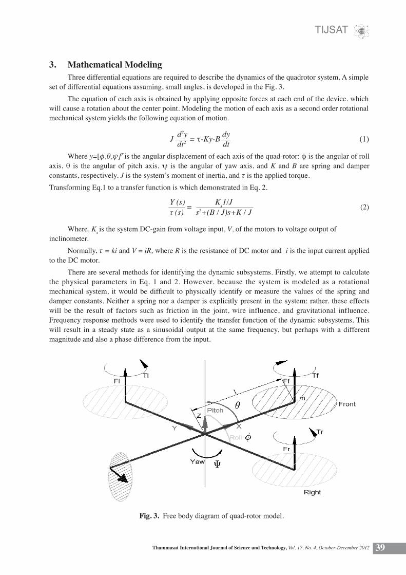
3. Mathematical Modeling Three differential equations are required to describe the dynamics of the quadrotor system. A simple set of differential equations assuming, small angles, is developed in the Fig. 3. The equation of each axis is obtained by applying opposite forces at each end of the device, which will cause a rotation about the center point. Modeling the motion of each axis as a second order rotational mechanical system yields the following equation of motion.
J d2y = τ-Ky-B dy (1) dt2 dt
Y (s) = Ks1/J (2)τ (s) s2+(B / J)s+K / J
Where y=[φ,θ,ψ]T is the angular displacement of each axis of the quad-rotor: φ is the angular of roll axis, θ is the angular of pitch axis, ψ is the angular of yaw axis, and K and B are spring and damper constants, respectively. J is the system’s moment of inertia, and τ is the applied torque. Transforming Eq.1 to a transfer function is which demonstrated in Eq. 2.
Where, Ks is the system DC-gain from voltage input, V, of the motors to voltage output of inclinometer. Normally, τ = ki and V = iR, where R is the resistance of DC motor and i is the input current applied to the DC motor. There are several methods for identifying the dynamic subsystems. Firstly, we attempt to calculate the physical parameters in Eq. 1 and 2. However, because the system is modeled as a rotational mechanical system, it would be difficult to physically identify or measure the values of the spring and damper constants. Neither a spring nor a damper is explicitly present in the system; rather, these effects will be the result of factors such as friction in the joint, wire influence, and gravitational influence. Frequency response methods were used to identify the transfer function of the dynamic subsystems. This will result in a steady state as a sinusoidal output at the same frequency, but perhaps with a different magnitude and also a phase difference from the input.
Fig. 3. Free body diagram of quad-rotor model.

TIJSAT
Thammasat International Journal of Science and Technology, Vol. 17, No. 4, October-December 201240
Frequency responses are classical identification techniques that use a sinusoidal signal through a range of frequencies as the system input and measure the corresponding response to characterize a system. For a stable system, a sinusoidal input V(t) = A sin(ωct) at a given frequency ωc and magnitude A will result in a steady state in a sinusoidal output at the same frequency, but perhaps with a different magnitude and also a phase difference from the input, as in Eq. 3.
Fig. 4. Frequency response of roll axis.
θ(s) = A G(jωc) sin(ωct + ϕ(ωc)) (3)
The roll transfer function was estimated to be:
φ (s) = 20.07е-0.7s (4)τ (s) s2+11.17s+45.65
0
-5
-10
-15
-20
-25
-30
-20 -40 -60 -80
-100 -120 -140 -160 -180 -200
Gain (dB.)
Phase (degree)
10-1 100 101
10-1 100 101
frequency (rda./sec.)
frequency (rda./sec.)

TIJSAT
Thammasat International Journal of Science and Technology, Vol. 17, No. 4, October-December 2012 41
φ (s) = 18.72е-1.3s (5)τ (s) s2+4.208s+11.19
Fig. 5. Frequency response of pitch axis.
The pitch transfer function was estimated to be:
5
0
-5
-10
-15
-20
-25
-20 -40 -60 -80
-100 -120 -140 -160 -180 -200 -220
Gain (dB.)
Phase (deg.)
rad/sec
rad/sec
10-1 100 101
10-1 100 101

TIJSAT
Thammasat International Journal of Science and Technology, Vol. 17, No. 4, October-December 201242
The yaw transfer function was estimated to be:
φ (s) = 20.07е-1.3s (6)τ (s) s2+19.17s+7565
Fig. 6. Frequency response of yaw axis.
5
0
-5
-10
-15
-20
-25
-20
-40
-60
-80
-100
-120
-140
-160
-180
-200
Gain (dB.)
10-1 100 101
10-1 100 101
Phase (degree)
rad/sec
frequency (rad./sec)

TIJSAT
Thammasat International Journal of Science and Technology, Vol. 17, No. 4, October-December 2012 43
Fig. 7. The quad-rotor control system structure.
Fig. 8. The second order module structure.
Where k is the index number, T is the sampling time, u(k) is the control signal, e(k) is the error between the desired and actual response, KP, K1, and KD are the proportional, integral, and derivative gains of PID.
4. Controller Design The conventional, proportional-integral-derivative, PID, controller is used for stabilizing and position tracking the system in each axis. They allow the designer, however, to satisfy only one closed loop specification, e.g., GM, PM, steady state error, etc. The structure of a quadrotor control system is demonstrated in Fig. 6. The PID controller is composed of the addition of three contributes, as shown in Fig. 7 and Eq. 7.
u(t) = Kpе(t) + ∫ Kiе(τ) + Kd de(t)
dt (7)
t
0
u(k) = u(k-1)+(KP+KiT+ Kd )e(k)+(KP+KiT+ Kd )e(k-1)+ Kd e(k-2) (8) 2 T 2 T T
Practically, the digital PID controller is employed to implement in a form of second order module structure [10], by transforming continuous time to discrete time, as shown in Eqs.8 and 9. The structure of second order module is shown in Fig. 8.
d(z) = b0 + b1z-1 + b2z
-2 (9)
1-a1z-1 + a2z
-2
where bo = KP+KIT+ KD , b1 = -KP+KIT+ KD , b2 = KD , a1 =-1,a2=0
2 T2 TT
е(k) m(k)
m(k-1)
m(k-2)
u(k)b0
b1
b2-a2
-a1
Z-1
Z-1

TIJSAT
Thammasat International Journal of Science and Technology, Vol. 17, No. 4, October-December 201244
4.1 Designing the PID controller Ziegler and Nichols method is applied for tuning a PID controller, which is based on a simple stability analysis [13-14]. Normally, PID allows the designer to satisfy only one closed loop specification, e.g., GM, PM, steady state error, etc. Because three parameters, KP, KI and KD must be adjusted in the design of PID controllers, root locus and Bode design techniques are usually not used directly. However, the derivative term in PID algorithm will increase the damping in the closed loop system while the integral term increases the system type and, hence, decreases steady state error. The drawback of the derivative term of PID controller is that if the task of a quad-rotor adds a step in the reference, the output of the derivative would present an impulse. This sharp movement can saturate the actuators and push away the system from the linear zone. Additionally, the drawback of the integral term is that the performance of the control system can decrease due to non-linear effect, due to the large integral action combined with an actuator saturation.
4.2 Optimal control (LQR+Kalman filter) Considering the structure of LQR+Kalman filter as in Fig. 9. We shall characterize the dynamic of the quadrotor by considering a discrete time linear model expressed in state space form:
Table 1 PID Parameters for Tuning Rules
PD 1.143 0 0.723895PID 1.524 1.608655 0.36095Roll PD 0.7431 0 0.39758PID 0.454 0.2085 0.45953Yaw PD 0.743 0 0.979PID 0.479 0.784 0.734
Pitch KP K1 KD
KP K1 KD
KP K1 KD
x [k+1] = Фx[k] + Гu[k] (10)
y [k] = Cx[k] + Du[k]+e(k) (11)
Where x [k] Є Rn is the state of the system at time k, u[k] Є Rm is the system input, y [k] Є Rp is the system output, and e[k] Є Rm is a zero mean white noise. Matrices Ф Є Rnxn and Г Є Rnxm are denoted as the dynamics matrix of the quadrotor. These dynamic matrices are obtained from system identification via frequency response, from the preliminary section of this paper. C Є Rpxn and D Є Rpxm are the measurement and disturbance matrices of the quad-rotor, respectively. Defining the output vector of the quad-rotor as: y[k] = [φ, θ, Ψ]T the control input of the quad-rotor is defined by the signals applied to DC-motor as the following form: u[k] = [u1, u2, u3]T where u1 is the control input of roll axis, u2 is the control input of pitch axis, and u3 is the control input of the yaw axis.

TIJSAT
Thammasat International Journal of Science and Technology, Vol. 17, No. 4, October-December 2012 45
x0 [k+1] = y[k] - yref[k]
x1 [k+1] = x2[k]
x2 [k+1] = -ω2x1 [k]-2ζω2 x2 [k]+Kω2u[k]
y[k] = x1[k]
[φref ,θref,Ψref]T[φ,θ,ψ]T
[φ,θ,ψ]T
u
u(t)
For those 2nd order systems of transfer function of each axis, the state space system is defined as follows:
Fig. 9. The structure of LQR+Kalman filter control system.
LQR+Kalman filter
Quadrotor
u[k] D/A
-K
D/A
Quadrotor
Observer
Inside Computer
x(k)
(12)
(13)
n n
Where yref [k] = [φref [k], θref [k],Ψref [k]]T is an angular position of each axis x2 [k] = ωm [k] is angular velocity
u[k] = -(K1(yref [k]-y[k])+K2 (ω[k]))x[k+1] = x[k]+ u[k] 0 0 1 -ω2
n Kω2 n -2ζωn
JN = (x [k]T Qx[k] + u[k]T RU[k]) N-1
k = 0 Σ 1
2
(14)
(15)
ФTP + PФ - PГR-1ГT P + Q = 0 (16)
x[k+1] = Фx[k]+Гu[k]
Given a plant (see Fig. 10) described by the state space model of the each axis.
Consider the problem of minimizing: The quadratic performance index for finite time (0 < k < N) is
By choosing the positive definite matrices, and solving the Riccati equation [10][11]:
Using K = -R-1 ГT P [10] for obtaining the optimal gains of state feedback controller

TIJSAT
Thammasat International Journal of Science and Technology, Vol. 17, No. 4, October-December 201246
4.3 Designing the gain of observer matrices for each axis via Kalman filter. Choosing the covariance matrices V1 = I and V2 = I, and solving the Riccati equation:
(17)
(18)
ФΣ + ΣФT - ΣCTV2 CΣ + V1 = 0 -1
L = ΣCTV2
x[k+1] = (Ф - ГR-1ГTP) x[k]
V(x) = xT Px
ФT P+PФ-PГR-1ГTP+Q = 0
-1
Where Σ = E[eeT]
So, the Kalman gain used in observer matrices are obtained by:
To check a stability of the system considered in Fig. 10.
u
K
xà
x
Г
L
c y
PLANT
Kalman filter
(zI - Ф)-1
C
+-
Г
(zI - Ф)-1
Fig. 10. the structure of LQR+Kalman.
(19)
(20)
(21)
The closed loop system of state feedback is given by:
Consider the Lyapunov function:
Where P is given by the Riccati equation:

TIJSAT
Thammasat International Journal of Science and Technology, Vol. 17, No. 4, October-December 2012 47
Choosing the positive definite matrices Q = 1000 and R = 1 Solving the Riccati equation We obtain the positive P Where for roll axis → P = For pitch axis → P = Using K = -R-1 ГTP for obtaining the optimal gains: For roll axis → K = [-1.2319 -0.1673] For pitch axis → K = [-1.2319 -0.1673] For yaw axis → K = [-1.8527 -0.3490]
The Lyapunov derivative is given by:
We can see that the Lyapunov derivative is negative, thus, the closed loop system is stable
4.4 Designing the gain matrices for controlling and stabilizing in each axis via LQR+Kalman filter. Giving a plant described in the preliminary section by discrete state space form of each axis:
V(x) = xT {(Ф-ГR-1ГTP)T P+
P(Ф-ГR-1ГTP)}x = x T {ФT P+ PФ-2PГR-1ГT P}x = -xT{PГR-1ГT}x-xTQx <0
x[k+1] = Фx[k]+Гu[k]
(22)
0.9939-0.6022
0.9915-0.8159
0.9921-0.7129
1000.150.2
1003.40.6
0.00500.4888
0.00370.3588
0.00300.3888
0.01910.9121
0.01790.7923
0.01590.5972
0.22000.15
0.62003.6
Where for roll axis → Ф = and Г = For pitch axis → Ф = and Г = For yaw axis → Ф = and Г =

TIJSAT
Thammasat International Journal of Science and Technology, Vol. 17, No. 4, October-December 201248
5. The experimental quad-rotor control system setup The experimental quadrotor control system has been structured and setup following Fig. 11.
Fig. 11. Experimental quad-rotor control system structure.
The above experimental structure consists of: - Personal computer, used as control algorithm - Interfacing circuit, consisting of 3-ch. 8 bits D/A converter - PWM generator - DC-motor, running at 20 kHz. - 4 board DC-motor driver (20 amperes) - Transducer, consisting of inclinometer and electronic compass - Quad-rotor
Using Eq. 18, L = ΣCTV2 , for obtaining the Kalman gains, by choosing the covariance matrices V1 = I and V2 = 1 for Eq. 17: For roll axis → L = [1.0000 -4.0878] For pitch axis → L = [1.0000 -11.0617] For yaw axis → L = [1.0000 -11.8469]
-1

TIJSAT
Thammasat International Journal of Science and Technology, Vol. 17, No. 4, October-December 2012 49
Experimental results The response in each of the three directions can be tuned based on the results the Ziegler-Nichols tuning and the LQR results.
Fig. 12. The experimental response of Pitch axis at 0 degrees.
Fig. 13. The experimental response of Roll axis at 0 degrees.

TIJSAT
Thammasat International Journal of Science and Technology, Vol. 17, No. 4, October-December 201250
Fig. 14. The experimental response of Yaw axis at 0 degrees.
Fig. 15. The experimental response of Pitch axis with disturbance.

TIJSAT
Thammasat International Journal of Science and Technology, Vol. 17, No. 4, October-December 2012 51
Fig. 16. The experimental response of Roll axis with disturbance.
Fig. 17. The experimental response of Yaw axis with disturbance.

TIJSAT
Thammasat International Journal of Science and Technology, Vol. 17, No. 4, October-December 201252
Fig. 18. The experimental trajectory of the Yaw axis.
Figs. 13-17 show the results from controlling the pitch, roll and yaw axis at the desired value of 0 degrees and 170 degrees, respectively. We see that the PD Controller can control the pitch, roll, and yaw axis for stabilizing but there remains a steady state error, while the PID Controller will decrease the steady state error due to the integral term. Additionally, the results show that the PID based Zigler-Nichols tuning rules do not provide a good starting estimation for PID gains, especially in the roll subsystems. This is due to the fact that the models used in each subsystem are attempts to represent grossly nonlinear dynamics as linear second order systems with transport delays. Those drawbacks of PID controller can improve the dynamic responses of a quad-rotor by using a state feedback controller based on a LQR+Kalman filter, designing optimal gains in order to get satisfactory specifications and a robust system. LQR can stabilize and decrease steady state error as well as decrease energy to control the system. The controlled system will be disturbed by external force, but remain stabilized. Moreover, Fig. 18 displays the responses of the system with PID and LQR gains to a desired input trajectory of a sinusoidal signal in the yaw subsystem. The results show that the LQR scheme can improve significantly the ability of the system to track the reference input, better than the PID scheme 6. Conclusion In this paper, we have developed and constructed a new model of quad-rotor and chosen the Kalman filter for estimating the states instead of a classical observer, and have used LQR as a controller in order to guarantee the system optimality. Experimental tuning of these gains provided satisfactory system performance. Output feedback control was also presented to demonstrate the ability to reject disturbances and to maintain the desired positions.

TIJSAT
Thammasat International Journal of Science and Technology, Vol. 17, No. 4, October-December 2012 53
7. Acknowledgement The author is deeply thankful for the financial support from an AIT scholarship. I also thank to Prof. Gustavo Belforte, visiting professor at AIT, for suggesting the theory of robust and adaptive control while the author was studying at AIT.
References [1] Puri, A. A Survey of Unmanned Aerial Vehicles (UAV) for Traffic Surveillance, CiteSeerX - Scientific Literature Digital Library and Search Engine (United States) [2] Patterson, M.C.L., Mulligan, A., Douglas, J., Robinson, J., and Wardell., L.; Volcano Surveillance by ACR Silver Fox, AIAA 2005-6954 [3] Kantner, M. Bodenheimer, B., Bendotti, P., and Murray R. M., An experimental comparison of controllers for a vectored thrust, ducted fan engine,” In Proceeding of the American control conferrence, Vol. 3, pp. 1956-1961, Seattle,WA, July 1955. [4] Galor, B., Fundamental concepts of vectored propulsion, J. of Propulsion 6(6); pp.747-757, 1990. [5] Galor, B. Vectored propulsion, Supermaneuverability and Robot Aircraft. Springer-Verlag, 1990. [6] Parsini, T., and Zoppoli, R. A receding horizon regulator for nonlinear systems snd a neural approximation, Automatica, Vol. 31, pp.1443-1451, 1995. [7] Choi, H.; Sturdza, P; and Murray, R.M.; Design and construction of a small ducted fan engine for nonlinear control experiments, In Proceeding of the American control conferrence, pp. 2618-2622, June 1994. [8] Bodenheimer, B., Bendotti, P., and Kantner, M., Linear parameter-varying control of a ducted fan engine, Int. J. Robust and Nonlinear Control , Vol. 6, pp. 1023-1044, 1996. [9] Beck, C.; Bodenheimer, B.; and Bendotti, P.; Lmi-based model reduction for a vectored thrust ducted fan experiment, in Proc. IEEE Control and Conferrence, 1995. [10] Doyle, J. C., Primbs, J., Shapiro, B., Nevistic H. V., Non-linear games: examples and counterexamples, Proceedings of the 35th IEEE conference on decision and control, Kobe, Japan, pp. 3915-3920. [11] Ljung, L. and Glover, K., Frequency domain versus time domain methods in system identification, J. of Automatica, 17(1):71-86, 1981. [12] Forssell, U. and Ljung, L. , Identification for control :some results on optimal experiment design, The 37th IEEE conferrence on Decision and Control, 1998. [13] Stanculeanu, I. and Borangiu, T., Quadrotor Black-Box System Identificatin, World Academy of Science, Engineering and Technology, pp. 54, 2011. [14] Charles L. Phillips and H. Troy Nagle, Digital Control System Analysis and Design, Prentice Hall, 3rd edition. [15] Lewis F.L. Applied Optimal Control and Estimation, Prentice Hall International Editions.