iec 60335-1 and/or en 60335-1 safety of household and ... · - page 7 of 76 - report no. ind...
TRANSCRIPT
- Page 1 of 76 -
Report No. IND 2050-1A/03
TEST REPORTIEC 60335-1 and/or EN 60335-1
Safety of household and similar electrical appliancesReport Reference No. ...................... : IND 2050-1A/03
Compiled by (+ signature) ................ : Roberto Tarro
Approved by (+ signature)................ : Marcello Pozzoli
Date of issue .................................... : 2003-07-30
CB Testing Laboratory................... : Nemko S.p.A. Phone +390392201201
Address ............................................ : Via Trento Trieste 116, 20046 Biassono (MI) ItalyTesting location/procedure............... : CBTL [ ] SMT [ ] TMP [ ]
Address ............................................ :
Applicant’s name............................ : FAAC S.p.AAddress ............................................ : Via Benini, 1
I - 40069 Zola Predosa (BO) Italy
Test specification:Standard........................................... : IEC 60335-1:2001 (Fourth Edition) and/or EN 60335-1:2002
Test procedure ................................. : CB Scheme
Non-standard test method…………..: N/A
Test Report Form No...................... : IEC60335_1GTRF Originator ........................................: Nemko AS
Master TRF.............................................: Dated 02-04
Copyright © 2001 IEC System for Conformity Testing and Certification of Electrical Equipment(IECEE), Geneva, Switzerland. All rights reserved.This publication may be reproduced in whole or in part for non-commercial purposes as long as the IECEEis acknowledged as copyright owner and source of the material. IECEE takes no responsibility for and willnot assume liability for damages resulting from the reader's interpretation of the reproduced material due toits placement and context.
Test item description ..................... : DRIVE FOR VERTICALLY MOVING SECTIONAL DOOR mod. 540
Trade Mark ....................................... : FAAC
Code................................................. : 1095540
Model/Type reference ...................... : 540 V
Serial number ................................... : 06030019
Ratings ............................................. : 800W 3.5A 230Vac 50Hz 50Nm IP54
23RPM 20µF Cl. I -20/+55°C

- Page 2 of 76 -
Report No. IND 2050-1A/03
TRF No. IEC60335_1G
Name and address of production-sites (Factories):
FAAC S.p.A.
Via Benini, 1
I - 40069 Zola Predosa (BO) Italy
Copy of marking plate and summary of test results (information/comments):
Summary of testing:
Appliances complies with EN60335-1:01 and EN12453:00 clause 5.2.1 (for electrical drive units)according to the tests performed and installation set up (provided by the manufacturer)
List of attachments:
Annex 1: EN 12453:00 Industrial, commercial and garage doors and gates –Safety in use of poweroperated doors –Clause 5.2.1 Electrical drive units
Annex 2:Pictures

- Page 3 of 76 -
Report No. IND 2050-1A/03
TRF No. IEC60335_1G
Test item particulars .................................................. :
Classification of installation and use............................ : DRIVE FOR VERTICALLY MOVING SECTIONALDOOR mod. 540
Supply Connection ....................................................... : Fixed wiring
...................................................................................... : 230 Vac / 50Hz 800W 3.5A
...................................................................................... : Motor winding thermally protected 140°C
Possible test case verdicts:- test case does not apply to the test object .................: N/A
- test object does meet the requirement.......................: P(Pass)
- test object does not meet the requirement.................: F(Fail)
Testing ..........................................................................:
Date of receipt of test item ............................................: 2003-07-17
Date (s) of performance of tests ...................................: from 2003-07-23 to 2003-07-30
General remarks:This report is not valid as a CB Test Report unless signed by an approved CB Testing Laboratory andappended to a CB Test Certificate issued by an NCB in accordance with IECEE 02.The test results presented in this report relate only to the object tested.This report shall not be reproduced, except in full, without the written approval of the Issuing testing laboratory.
"(see Enclosure #)" refers to additional information appended to the report."(see appended table)" refers to a table appended to the report.
Throughout this report a comma (point) is used as the decimal separator.

- Page 4 of 76 -
Report No. IND 2050-1A/03
TRF No. IEC60335_1G
General product information:Automated System 540
TECHNICAL SPECIFICATION

- Page 5 of 76 -
Report No. IND 2050-1A/03
IEC 60335-1
Clause Requirement - Test Result - Remark Verdict
TRF No. IEC60335_1G
5 GENERAL CONDITIONS FOR THE TESTS
Tests performed according to cl. 5, e.g. nature ofsupply, sequence of testing, etc.
P
6 CLASSIFICATION __
6.1 Protection against electric shock:Class 0, 0I, I, II, III ................................................... :
class I equipment P
Delete "class 0" and "class 0I" (EN 60335-1) .......: P
6.2 Protection against harmful ingress of water IP54 P
7 MARKING AND INSTRUCTIONS
7.1 Rated voltage or voltage range (V) ......................... : 230V P
Nature of supply....................................................... : Vac P
Rated frequency (Hz) .............................................. : 50Hz P
Rated power input (W):............................................ : 800W P
Rated current (A) .................................................... : 3.5A max P
Manufacturer's or responsible vendor's name,trademark or identification mark.............................. :
FAAC P
Code reference........................................................ : 109540 P
Model or type reference........................................... : 540 V P
Symbol 5172 of IEC 60417, for Class II appliances N
IP number, other than IPX0..................................... : IPX4 P
7.2 Warning for stationary appliances for multiple supply N
Warning placed in vicinity of terminal cover N
7.3 Range of rated values marked with the lower andupper limits separated by a hyphen
N
Different rated values marked with the valuesseparated by an oblique stroke
N
7.4 Appliances adjustable for different rated voltages,the voltage setting is clearly discernible
N
7.5 Appliances with more than one rated voltage or oneor more rated voltage ranges, marked with ratedinput or rated current for each rated voltage or range,unless
N

- Page 6 of 76 -
Report No. IND 2050-1A/03
IEC 60335-1
Clause Requirement - Test Result - Remark Verdict
TRF No. IEC60335_1G
the power input is related to the mean value of therated voltage range
N
Relation between marking for upper and lower limitsof rated power input or rated current and voltage isclear
N
7.6 Correct symbols used P
7.7 Connection diagram fixed to appliances to beconnected to more than two supply conductors andappliances for multiple supply
N
7.8 Except for type Z attachment, terminals for connection to the supply mains indicatedas follows:
P
- marking of terminals exclusively for the neutralconductor (N)
P
- marking of protective earthing terminals (symbol5019 of IEC 60417)
P
- marking not placed on removable parts P
7.9 Marking or placing of switches which may cause ahazard
N
7.10 Indications of switches on stationary appliances andcontrols on all appliances by use of figures, letters orother visual means................................................... :
N
The figure 0 indicates only OFF position, unless noconfusion with the OFF position
N
7.11 Indication for direction of adjustment of controls In the instruction sheet P
7.12 Instructions for safe use provided P
7.12.1 Sufficient details for installation supplied P
7.12.2 Stationary appliances not fitted with means fordisconnection from the supply mains having acontact separation in all poles that provide fulldisconnection under overvoltage category III, theinstructions state that means for disconnection mustbe incorporated in the fixed wiring in accordance withthe wiring rules
P
7.12.3 Insulation of the fixed wiring in contact with partsexceeding 50 K during clause 11; instructions statingthat the fixed wiring must be protected
N
7.12.4 Instructions for built-in appliances: N

- Page 7 of 76 -
Report No. IND 2050-1A/03
IEC 60335-1
Clause Requirement - Test Result - Remark Verdict
TRF No. IEC60335_1G
- dimensions of space N
- dimensions and position of supporting means N
- distances between parts and surrounding structure N
- dimensions of ventilation openings andarrangement
N
- connection to supply mains and interconnection ofseparate components
N
- plug accessible after installation, unless N
a switch complying with 24.3 N
7.12.5 Replacement cord instructions, type X attachmentwith a specially prepared cord
N
Replacement cord instructions, type Y attachment N
Replacement cord instructions, type Z attachment N
7.13 Instructions and other texts in an official language Instruction sheet in Italian,English, French, Deutsche
P
7.14 Marking clearly legible and durable P
7.15 Marking on a main part P
Marking clearly discernible from the outside, ifnecessary after removal of a cover
P
For portable appliances, cover can be removed oropened without a tool
N
For stationary appliances, name, trademark oridentification mark and model or type referencevisible after installation
P
For fixed appliances, name, trademark oridentification mark and model or type referencevisible after installation according to the instructions
P
Indications for switches and controls placed on ornear the components. Marking not on parts whichcan be positioned or repositioned in such a way thatthe marking is misleading
N
7.16 Marking of a possible replaceable thermal link orfuse link clearly visible with regard to replacing thelink
Fuses 6.3A on the PCB P
8 PROTECTION AGAINST ACCESS TO LIVE PARTS

- Page 8 of 76 -
Report No. IND 2050-1A/03
IEC 60335-1
Clause Requirement - Test Result - Remark Verdict
TRF No. IEC60335_1G
8.1 Adequate protection against accidental contact withlive parts
P
8.1.1 Requirement applies for all positions, detachableparts removed
No detachable part withoutusage of a tool
N
Insertion or removal of lamps, protection againstcontact with live parts of the lamp cap
No Lamps N
Use of test probe B of IEC 61032: no contact withlive parts
P
8.1.2 Use of test probe 13 of IEC 61032 through openingsin class 0 appliances and class II appliances/constructions: no contact with live parts
N
Test probe 13 also applied through openings inearthed metal enclosures having a non-conductivecoating: no contact with live parts
N
8.1.3 For appliances other than class II, use of test probe41 of IEC 61032: no contact with live parts of visibleglowing heating elements
N
8.1.4 Accessible part not considered live if: P
- safety extra-low a.c. voltage: peak value notexceeding 42.4 V
P
- safety extra-low d.c. voltage: not exceeding 42.4 V N
- or separated from live parts by protectiveimpedance
N
If protective impedance: d.c. current not exceeding2 mA, and
N
a.c. peak value not exceeding 0.7 mA N
- for peak values over 42.4 V up to and including450 V, capacitance not exceeding 0,1 µF
N
- for peak values over 450 V up to and including15 kV, discharge not exceeding 45 µC
N
8.1.5 Live parts protected at least by basic insulation before installation or assembly: P
- built-in appliances N
- fixed appliances P
- appliances delivered in separate units N

- Page 9 of 76 -
Report No. IND 2050-1A/03
IEC 60335-1
Clause Requirement - Test Result - Remark Verdict
TRF No. IEC60335_1G
8.2 Class II appliances and constructions constructed sothat there is adequate protection against accidentalcontact with basic insulation and metal partsseparated from live parts by basic insulation only
N
Only possible to touch parts separated from liveparts by double or reinforced insulation
P
9 STARTING OF MOTOR-OPERATED APPLIANCES __
Requirements and tests are specified in part 2 whennecessary
N
10 POWER INPUT AND CURRENT __
10.1 Power input at normal operating temperature, ratedvoltage and normal operation not deviating fromrated power input by more than shown in table 1
(see appended table) P
10.2 Current at normal operating temperature, ratedvoltage and normal operation not deviating fromrated current by more than shown in table 2
N
11 HEATING __
11.1 No excessive temperatures in normal use P
11.2 Placing and mounting of appliance as described In the instruction sheet P
11.3 Temperature rises, other than of windings,determined by thermocouples
P
Temperature rises of windings determined byresistance method, unless
P
the windings makes it difficult to make the necessaryconnections
N
11.4 Heating appliances operated under normal operationat 1.15 times rated power input .............................. :
N
11.5 Motor-operated appliances operated under normaloperation at most unfavourable voltage between0.94 and 1.06 times rated voltage........................... :
Operated at 243.8Vac P
11.6 Combined appliances operated under normaloperation at most unfavourable voltage between0.94 and 1.06 times rated voltage........................... :
Not a combined appliances N

- Page 10 of 76 -
Report No. IND 2050-1A/03
IEC 60335-1
Clause Requirement - Test Result - Remark Verdict
TRF No. IEC60335_1G
11.7 Operation duration corresponding to the mostunfavourable conditions of normal use
Adjusted at the mostunfavourable condition:
Maximum power, Maximum working time Minimum pause time- Maximum load
P
11.8 Temperature rises not exceeding values in table 3 (see appended tables) P
Protective devices do not operate Use frequency (S3) 40% asdescribed on the instructionsheet.
P
Sealing compound does not flow out P
13 LEAKAGE CURRENT AND ELECTRIC STRENGTH AT OPERATINGTEMPERATURE
__
13.1 Leakage current not excessive and electric strengthadequate
P
Heating appliances operated at 1.15 times ratedpower input .............................................................. :
N
Motor-operated appliances and combinedappliances supplied at 1.06 times rated voltage..... :
Tested at 243.8V P
Protective impedance and radio interference filtersdisconnected before carrying out the tests
Interference filter disconnected(Capacitors )
P
13.2 Leakage current measured by means of the circuitdescribed in figure 4 of IEC 60990
P
Leakage current measurements (see appended table) P
13.3 Electric strength tests according to table 4 (see appended table) P
No breakdown during the tests P
14 TRANSIENT OVERVOLTAGES __
Appliances withstand the transient overvoltages towhich they may be subjected
N
Clearances having a value less than specified intable 16 subjected to an impulse voltage test, the testvoltage specified in table 6
Minimum clearance >0.5mm N
No flashover during the test, unless of functionalinsulation
N
In case of flashover of functional insulation, theappliance complies with clause 19 with the clearanceshort circuited
N
- Page 11 of 76 -
Report No. IND 2050-1A/03
IEC 60335-1
Clause Requirement - Test Result - Remark Verdict
TRF No. IEC60335_1G
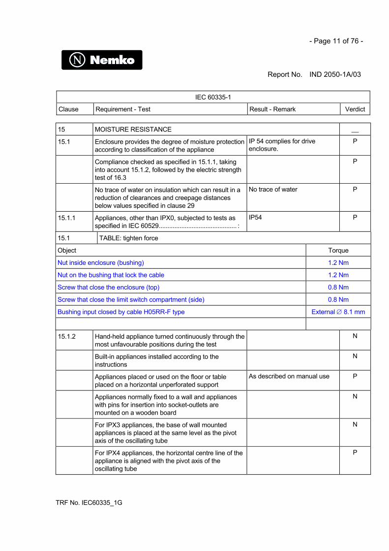
15 MOISTURE RESISTANCE __
15.1 Enclosure provides the degree of moisture protectionaccording to classification of the appliance
IP 54 complies for driveenclosure.
P
Compliance checked as specified in 15.1.1, takinginto account 15.1.2, followed by the electric strengthtest of 16.3
P
No trace of water on insulation which can result in areduction of clearances and creepage distancesbelow values specified in clause 29
No trace of water P
15.1.1 Appliances, other than IPX0, subjected to tests asspecified in IEC 60529............................................. :
IP54 P
15.1 TABLE: tighten force
Object Torque
Nut inside enclosure (bushing) 1.2 Nm
Nut on the bushing that lock the cable 1.2 Nm
Screw that close the enclosure (top) 0.8 Nm
Screw that close the limit switch compartment (side) 0.8 Nm
Bushing input closed by cable H05RR-F type External ∅ 8.1 mm
15.1.2 Hand-held appliance turned continuously through themost unfavourable positions during the test
N
Built-in appliances installed according to theinstructions
N
Appliances placed or used on the floor or tableplaced on a horizontal unperforated support
As described on manual use P
Appliances normally fixed to a wall and applianceswith pins for insertion into socket-outlets aremounted on a wooden board
N
For IPX3 appliances, the base of wall mountedappliances is placed at the same level as the pivotaxis of the oscillating tube
N
For IPX4 appliances, the horizontal centre line of theappliance is aligned with the pivot axis of theoscillating tube
P

- Page 12 of 76 -
Report No. IND 2050-1A/03
IEC 60335-1
Clause Requirement - Test Result - Remark Verdict
TRF No. IEC60335_1G
However, for appliances normally used on the flooror table, the movement is limited to two times 90° fora period of 5 min, the support being placed at thelevel of the pivot axis of the oscillating tube
P
Wall-mounted appliances, take into account thedistance to the floor stated in the instructions
N
Appliances with type X attachment fitted with aflexible cord as described
P
Detachable parts tested as specified No detachable part N
15.2 Spillage of liquid does not affect the electricalinsulation
N
Appliances with type X attachment fitted with aflexible cord as described
N
Appliances incorporating an appliance inlet testedwith or without an connector, whichever is mostunfavourable
N
Detachable parts removed N
Overfilling test with additional amount ofwater, over a period of 1 min (l)............................... :
N
The appliance withstands the electric strength test of16.3
N
No trace of water on insulation that can result in areduction of clearances and creepage distancesbelow values specified in clause 29
N
15.3 Appliances proof against humid conditions P
Humidity test for 48 h in a humidity cabinet Relative humidity 93%Temperature 30°C
P
The appliance withstands the tests of clause 16 P
16 LEAKAGE CURRENT AND ELECTRIC STRENGTH
16.1 Leakage current not excessive and electric strengthadequate
P
Protective impedance disconnected from live partsbefore carrying out the tests
N
16.2 Single-phase appliances: test voltage 1.06 timesrated voltage ............................................................ :
243.8V P

- Page 13 of 76 -
Report No. IND 2050-1A/03
IEC 60335-1
Clause Requirement - Test Result - Remark Verdict
TRF No. IEC60335_1G
Three-phase appliances: test voltage 1.06 timesrated voltage divided by √3...................................... :
N
Leakage current measurements (see appended table) P
16.3 Electric strength tests according to table 7 (see appended table) P
No breakdown during the tests P
17 OVERLOAD PROTECTION OF TRANSFORMERS AND ASSOCIATED CIRCUITS
No excessive temperatures in transformer orassociated circuits in event of short-circuits likely tooccur in normal use
No excessive temperaturemeasured in short secondarycircuit of the transformer.
P
Appliance supplied with 1.06 or 0.94 times ratedvoltage and the most unfavourable short-circuit oroverload likely to occur in normal use applied........ :
P
Temperature rise of insulation of the conductors ofsafety extra-low voltage circuits not exceeding therelevant value specified in table 3 by more than 15 K
P
Temperature of the winding not exceeding the valuespecified in table 8,
(see appended table) P
however limits do not apply to fail-safe transformerscomplying with sub-clause 15.5 of IEC 61558-1
N
18 ENDURANCE
Requirements and tests are specified in part 2 whennecessary
N
19 ABNORMAL OPERATION
19.1 The risk of fire or mechanical damage underabnormal or careless operation obviated
P
Electronic circuits so designed and applied that afault will not render the appliance unsafe
P
19.2 Test of appliance with heating elements withrestricted heat dissipation; test voltage (V): powerinput of 0.85 times rated power input...................... :
N
19.3 Test of 19.2 repeated; test voltage (V): power inputof 1.24 times rated power input............................... :
N
19.4 Test conditions as in cl. 11, any control limiting thetemperature during tests of cl. 11 short-circuited
N

- Page 14 of 76 -
Report No. IND 2050-1A/03
IEC 60335-1
Clause Requirement - Test Result - Remark Verdict
TRF No. IEC60335_1G
19.5 Test of 19.4 repeated on Class 0I and I applianceswith tubular sheathed or embedded heatingelements. No short-circuiting, but one end of theelement connected to the elements sheath
N
The test repeated with reversed polarity and theother end of the heating element connected to thesheath
N
The test is not carried out on appliances intended tobe permanently connected to fixed wiring and onappliances where an all-pole disconnection occursduring the test of 19.4
N
19.6 Appliances with PTC heating elements tested atrated voltage, establishing steady conditions
N
The working voltage of the PTC heating element isincreased by 5% and the appliance is operated untilsteady conditions are re-established. The voltage isthen increased in similar steps until 1.5 timesworking voltage or until the PTC heating elementruptures
N
19.7 Stalling test by locking the rotor if the locked rotortorque is smaller than the full load torque or lockingmoving parts of other appliances
The motor winding is protectedby self resetting thermalprotection T=140°C
P
Locked rotor, motor capacitors open-circuited orshort-circuited, if required
Motor capacitors complyingwith EN 60252
P
Winding temperatures not exceeding valuesspecified in table 8
(see appended table) P
19.8 Three-phase motors operated at rated voltage withone phase disconnected
N
19.9 Running overload test on appliances incorporatingmotors intended to be remotely or automaticallycontrolled or liable to be operated continuously
The customer declares that thevariation of motor chargecurrent with the applianceloaded or unloaded is a littletenth of Ampere due to gearsNormal operation motor current0.1.79A.
Overloaded operation motorcurrent 2.0A
P
Winding temperatures not exceeding values asspecified
(see appended table) P

- Page 15 of 76 -
Report No. IND 2050-1A/03
IEC 60335-1
Clause Requirement - Test Result - Remark Verdict
TRF No. IEC60335_1G
19.10 Series motor operated at 1.3 times rated voltage for1 min......................................................................... :
N
During the test, parts not being ejected from theappliance
N
19.11 Electronic circuits, compliance checked byevaluation of the fault conditions specified in 19.11.2for all circuits or parts of circuits, unless they complywith the conditions specified in 19.11.1
P
19.11.1 Before applying the fault conditions a) to f) in 19.11.2, it is checked if circuits or partsof circuit meet both of the following conditions:
__
- the electronic circuit is a low-power circuit, that is,the maximum power at low-power points does notexceed 15 W according to the tests specified
P
- the protection against electric shock, fire hazard,mechanical hazard or dangerous malfunction inother parts of the appliance does not rely on thecorrect functioning of the electronic circuit
Mechanical hazard may berelated with fault condition onlow power circuit
N
19.11.2 Fault conditions applied one at a time, the appliance operated under conditionsspecified in cl. 11, but supplied at rated voltage, the duration of the tests as specified:
__
a) short circuit of functional insulation if clearances orcreepage distances are less than the valuesspecified in 29
No distances below the limits N
b) open circuit at the terminals of any component - Open circuit of FC1 - FC2(limiting switch) the drivestops to operate no hazard
- Open circuit of IN1 – IN2commands connector J2the drive stops to operateno hazard.
- Open R1, R2no hazard
P
c) short circuit of capacitors, unless they comply withIEC 60384-14
C1, C2 Approved component N

- Page 16 of 76 -
Report No. IND 2050-1A/03
IEC 60335-1
Clause Requirement - Test Result - Remark Verdict
TRF No. IEC60335_1G
d) short circuit of any two terminals of an electroniccomponent, other than integrated circuits. This faultcondition is not applied between the two circuits ofan optocoupler
- Short circuit of motorconnector J3: fuse 6.3Aimmediately blows out
- Short circuit of FC1 - FC2(limiting switch) no hazard
- Short circuit of IN1- IN2 (commands) connector J2no hazard
P
e) failure of triacs in the diode mode No triac N
f) failure of an integrated circuit. The possiblehazardous situations of the appliance are assessedto ensure that safety does not rely on the correctfunctioning of such a component
No integrated circuit N
19.11.3 If the appliance incorporates a protective electroniccircuit which operates to ensure compliance withclause 19, the relevant test is repeated with a singlefault simulated, as indicated in a) to f) of 19.11.2
N
During and after each test the following is checked: __
- the temperature rise of the windings do not exceedthe values specified in table 8
P
- the appliance complies with the conditions specifiedin 19.13
P
- any current flowing through protective impedancenot exceeding the limits specified in 8.1.4
N
If a conductor of a printed board becomes open-circuited, the appliance is consideredto have withstood the particular test, provided all three of the following conditions aremet:
N
- the material of the printed circuit board withstandsthe burning test of annex E
N
- any loosened conductor does not reduce theclearances or creepage distances between live partsand accessible metal parts below the valuesspecified in cl. 29
N
- the appliance withstands the tests of 19.11.2 withopen-circuited conductor bridged
N

- Page 17 of 76 -
Report No. IND 2050-1A/03
IEC 60335-1
Clause Requirement - Test Result - Remark Verdict
TRF No. IEC60335_1G
19.12 If the safety of the appliance for any of the faultconditions specified in 19.11.2 depends on theoperation of a miniature fuse-link complying withIEC 60127, the test is repeated, measuring thecurrent flowing through the fuse-link; measuredcurrent (A); rated current of the fuse-link (A) .......... :
- Short circuit of motorconnector J3: fuse 6.3Aimmediately blow out
P
19.13 During the tests the appliance does not emit flames,molten metal, poisonous or ignitable gas inhazardous amounts
No flamesNo molten metalNo poisonous or ignitable gas
P
Temperature rises not exceeding the values shownin table 9
(see appended table) P
Enclosures not deformed to such an extent thatcompliance with cl. 8 is impaired
Enclosure not deformed P
If the appliance can still be operated it complies with20.2
P
Insulation, other than of class III appliance, withstand the electric strength test of 16.3,the test voltage specified in table 4:
- basic insulation ...................................................... : 500Vac (on SELV circuit) P
- supplementary insulation ...................................... : 1750Vac (between live partsand accessible metal parts)
P
- reinforced insulation .............................................. : 3000Vac (between live partsand accessible metal parts)
3750Vac (between pri-sec oftransformer)
P
20 STABILITY AND MECHANICAL HAZARDS __
20.1 Adequate stability N
Tilting test through an angle of 10° (appliance placedon an inclined plane/horizontal plane); appliancedoes not overturn
Fixed Appliance N
Tilting test repeated on appliances with heatingelements, angle of inclination increased to 15°
N
Possible heating test in overturned position;temperature rise does not exceed values shown intable 9
N

- Page 18 of 76 -
Report No. IND 2050-1A/03
IEC 60335-1
Clause Requirement - Test Result - Remark Verdict
TRF No. IEC60335_1G
20.2 Moving parts adequately arranged or enclosed as toprovide protection against personal injury
Moving parts are enclosed toprovide protection againstpersonal injury. There is a shaftthat comes out of theenclosure to open and closethe door that is not possible toinclude in a box for applicationof the appliance
P
Protective enclosures, guards and similar parts arenon-detachable
Plastic enclosure fixed byscrews
P
Adequate mechanical strength and fixing ofprotective enclosures
P
Self-resetting thermal cut-outs and overcurrentprotective devices not causing a hazard, byunexpected reclosure
P
Not possible to touch dangerous moving parts withtest probe
Once properly installed withadequate driven part minimumhazard possible
P
21 MECHANICAL STRENGTH __
Appliance has adequate mechanical strength and isconstructed as to withstand rough handling
P
No damage after three blows applied to various partsof the enclosure, impact energy 0,5 ± 0,04 J
P
If necessary, supplementary or reinforced insulationsubjected to the electric strength test of 16.3
N
If necessary, repetition of groups of three blows on anew sample
N
22 CONSTRUCTION __
22.1 Appliance marked with the first numeral of the IPsystem, relevant requirements of IEC 60529 arefulfilled
IP54 P
22.2 Stationary appliance: means to provide all-pole disconnection from the supplyprovided, the following means being available:
P
- a supply cord fitted with a plug N
- a switch complying with 24.3 N

- Page 19 of 76 -
Report No. IND 2050-1A/03
IEC 60335-1
Clause Requirement - Test Result - Remark Verdict
TRF No. IEC60335_1G
- a statement in the instruction sheet that adisconnection incorporated in the fixed wiring is to beprovided
In the instruction sheet P
- an appliance inlet N
Singe-pole switches and single-pole protectivedevices for the disconnection of heating elements insingle-phase permanently connected class Iappliances, connected in the phase conductor
N
22.3 Appliance provided with pins: no undue strain onsocket-outlets
N
Applied torque not exceeding 0.25 Nm N
Pull force of 50N to each pin after the appliance hasbeing placed in the heating cabinet; when cooled toroom temperature the pins are not displaced bymore than 1mm
N
Each pin subjected to a torque of 0.4Nm; the pinsare not rotating unless rotating does not impaircompliance with the standard
N
22.4 Appliance for heating liquids and appliance causingundue vibration not provided with pins for insertioninto socket-outlets
N
22.5 No risk of electric shock when touching the pins ofthe plug
N
22.6 Electrical insulation not affected by condensing wateror leaking liquid
P
Electrical insulation of Class II appliances notaffected in case of a hose rupture or seal leak
N
22.7 Adequate safeguards against the risk of excessivepressure in appliances provided with steam-producing devices
N
22.8 Electrical connections not subject to pulling duringcleaning of compartments to which access can begained without the aid of a tool, and that are likely tobe cleaned in normal use
N
22.9 Insulation, internal wiring, windings, commutatorsand slip rings not exposed to oil, grease or similarsubstances
P

- Page 20 of 76 -
Report No. IND 2050-1A/03
IEC 60335-1
Clause Requirement - Test Result - Remark Verdict
TRF No. IEC60335_1G
Adequate insulating properties of oil or grease towhich insulation is exposed
N
22.10 Location or protection of reset buttons of non-self-resetting controls is so that accidental resetting isunlikely
N
22.11 Reliable fixing of non-detachable parts that providethe necessary degree of protection against electricshock, moisture or contact with moving parts
Enclosure fixed by screws P
Obvious locked position of snap-in devices used forfixing such parts
N
No deterioration of the fixing properties of snap-indevices used in parts that are likely to be removedduring installation or servicing
N
Tests as described N
22.12 Handles, knobs etc. fixed in a reliable manner No handles N
Fixing in wrong position of handles, knobs etc.indicating position of switches or similar componentsnot possible
N
Axial force 15 N applied to parts, the shape being sothat an axial pull is unlikely to be applied
N
Axial force 30 N applied to parts, the shape being sothat an axial pull is likely to be applied
N
22.13 Unlikely that handles, when gripped as in normaluse, make the operators hand touch parts having atemperature rise exceeding the value specified forhandles which are held for short periods only
Not intended to be touchedduring normal use
N
22.14 No ragged or sharp edges creating a hazard for theuser in normal use, or during user maintenance
P
No exposed pointed ends of self tapping screws etc.,liable to be touched by the user in normal use orduring user maintenance
P
22.15 Storage hooks and the like for flexible cords smoothand well rounded
N
22.16 Automatic cord reels cause no undue abrasion ordamage to the sheath of the flexible cord, nobreakage of conductors strands, no undue wear ofcontacts
N

- Page 21 of 76 -
Report No. IND 2050-1A/03
IEC 60335-1
Clause Requirement - Test Result - Remark Verdict
TRF No. IEC60335_1G
Cord reel tested with 6000 operations, as specified N
Electric strength test of 16.3, voltage of 1000 Vapplied
N
22.17 Spacers not removable from the outside by hand orby means of a screwdriver or a spanner
N
22.18 Current-carrying parts and other metal parts resistantto corrosion under normal conditions of use
P
22.19 Driving belts not used as electrical insulation P
22.20 Direct contact between live parts and thermalinsulation effectively prevented, unless material usedis non-corrosive, non-hygroscope and non-combustible
No thermal insulation P
Compliance is checked by inspection and, ifnecessary, by appropriate test
N
22.21 Wood, cotton, silk, ordinary paper and fibrous orhygroscopic material not used as insulation, unlessimpregnated
Not used P
22.22 Appliances not containing asbestos Not used P
22.23 Oils containing polychlorinated biphenyl (PCB) notused
Not used P
22.24 Bare heating elements adequately supported N
In case of rupture, the heating conductor is unlikelyto come in contact with accessible metal parts
N
22.25 Sagging heating conductors cannot come intocontact with accessible metal parts
N
22.26 The insulation between parts operating at safetyextra-low voltage and other live parts complies withthe requirements for double or reinforced insulation
P
22.27 Parts connected by protective impedance separatedby double or reinforced insulation
N
22.28 Metal parts of Class II appliances conductivelyconnected to gas pipes or in contact with water:separated from live parts by double or reinforcedinsulation
N
22.29 Class II appliances permanently connected to fixedwiring so constructed that the required degree ofaccess to live parts is maintained after installation
N

- Page 22 of 76 -
Report No. IND 2050-1A/03
IEC 60335-1
Clause Requirement - Test Result - Remark Verdict
TRF No. IEC60335_1G
22.30 Parts serving as supplementary or reinforcedinsulation fixed so that they cannot be removedwithout being seriously damaged, or
N
so constructed that they cannot be replaced in anincorrect position, and so that if they are omitted, theappliance is rendered inoperable or manifestlyincomplete
N
22.31 Clearances and creepage distances oversupplementary and reinforced insulation not reducedbelow values specified for supplementary insulation
P
Creepage distances and clearances oversupplementary or reinforced insulation not reducedto less than 50% of values specified in 29 if wires,screws etc. becomes loose
P
22.32 Supplementary and reinforced insulation designed orprotected against deposition of dirt or dust
P
Supplementary insulation of natural or syntheticrubber resistant to ageing, or arranged anddimensioned so that creepage distances are notreduced below values specified in 29.2
N
Ceramic material not tightly sintered, similar materialor beads alone not used as supplementary orreinforced insulation
Not used P
Oxygen bomb test at 70 °C for 96 h and 16 h at roomtemperature
N
22.33 Conductive liquids that are or may becomeaccessible in normal use are not in direct contactwith live parts
N
Electrodes not used for heating liquids N
For class II constructions, conductive liquids that areor may become accessible in normal use, not indirect contact with basic or reinforced insulation
N
For class II constructions, conductive liquids whichare in contact with live parts, not in direct contactwith reinforced insulation
N
22.34 Shafts of operating knobs, handles, levers etc. notlive, unless the shaft is not accessible when the partis removed
P

- Page 23 of 76 -
Report No. IND 2050-1A/03
IEC 60335-1
Clause Requirement - Test Result - Remark Verdict
TRF No. IEC60335_1G
22.35 Handles, levers and knobs, held or actuated innormal use, not becoming live in the event of aninsulation fault
P
Such parts being of metal, and their shafts or fixingsare likely to become live in the event of an insulationfault, they are either adequately covered byinsulation material, or their accessible parts areseparated from their shafts or fixings bysupplementary insulation
N
This requirement does not apply to handles, leversand knobs on stationary appliances other than thoseof electrical components, provided they are eitherreliably connected to an earthing terminal or earthingcontact, or separated from live parts by earthedmetal
N
22.36 Handles continuously held in the hand in normal useare so constructed that when gripped as in normaluse, the operators hand is not likely to touch metalparts, unless they are separated from live parts bydouble or reinforced insulation
N
22.37 Capacitors in Class II appliances not connected toaccessible metal parts, unless complying with 22.42
N
Metal casings of capacitors in Class II appliancesseparated from accessible metal parts bysupplementary insulation, unless complying with22.42
N
22.38 Capacitors not connected between the contacts of athermal cut-out
P
22.39 Lamp holders used only for the connection of lamps N
22.40 Motor-operated appliances and combinedappliances intended to be moved while in operation,or having accessible moving parts, fitted with aswitch to control the motor. The actuating member ofthe switch being easily visible and accessible
N
22.41 No components, other than lamps, containingmercury
P
22.42 Protective impedance consisting of at least twoseparate components
N
Values specified in 8.1.4 not exceeded if any one ofthe components are short-circuited or open-circuited
N

- Page 24 of 76 -
Report No. IND 2050-1A/03
IEC 60335-1
Clause Requirement - Test Result - Remark Verdict
TRF No. IEC60335_1G
22.43 Appliances adjustable for different voltages,accidental changing of the setting of the voltageunlikely to occur
N
22.44 Appliances are not allowed to have an enclosure thatis shaped and decorated so that the appliance islikely to be treated as a toy by children
Not shaped as a toy P
22.45 When air is used as reinforced insulation, clearancesnot reduced below the values specified in 29.1.4 dueto deformation as a result of an external forceapplied to the enclosure
P
23 INTERNAL WIRING __
23.1 Wireways smooth and free from sharp edges P
Wires protected against contact with burrs, coolingfins etc.
P
Wire holes in metal well rounded or provided withbushings
P
Wiring effectively prevented from coming into contactwith moving parts
P
23.2 Beads etc. on live wires cannot change theirposition, and are not resting on sharp edges orcorners
N
Beads inside flexible metal conduits contained withinan insulating sleeve
N
23.3 Electrical connections and internal conductorsmovable relatively to each other not exposed toundue stress
N
Flexible metallic tubes not causing damage toinsulation of conductors
N
Open-coil springs not used N
Adequate insulating lining provided inside a coiledspring, the turns of which touch one another
N
No damage after 10 000 flexings for conductorsflexed during normal use or 100 flexings forconductors flexed during user maintenance
N
Electric strength test, 1000 V between live parts andaccessible metal parts
N
23.4 Bare internal wiring sufficiently rigid and fixed N

- Page 25 of 76 -
Report No. IND 2050-1A/03
IEC 60335-1
Clause Requirement - Test Result - Remark Verdict
TRF No. IEC60335_1G
23.5 The insulation of internal wiring withstanding theelectrical stress likely to occur in normal use
P
No breakdown when a voltage of 2000 V is appliedfor 15 min between the conductor and metal foilwrapped around the insulation
P
23.6 Sleeving used as supplementary insulation oninternal wiring retained in position by positive means
N
23.7 The colour combination green/yellow used only forearthing conductors
P
23.8 Aluminium wires not used for internal wiring P
23.9 No lead-tin soldering of stranded conductors wherethey are subject to contact pressure, unless
P
clamping means so constructed that there is no riskof bad contact due to cold flow of the solder
N
24 COMPONENTS __
24.1 Components comply with safety requirements inrelevant IEC standards
P
List of components (see appended table) P
Components not tested and found to comply withrelevant IEC standard for the number of cyclesspecified are tested in accordance with 24.1.1 to24.1.6
N
Components not tested and found to comply withrelevant IEC standard, components not marked ornot used in accordance with its marking, testedunder the conditions occurring in the appliance
N
24.1.1 Capacitors likely to be permanently subjected to thesupply voltage and used for radio interferencesuppression or for voltage dividing, complying withIEC 60384-14, or
P
tested according to annex F N
24.1.2 Safety isolating transformers complying with IEC61558-2-6, or
Approved in according to EN60742
P
tested according to annex G P
24.1.3 Switches complying with IEC 61058-1, the number ofcycles of operation being at least 10 000, or
N

- Page 26 of 76 -
Report No. IND 2050-1A/03
IEC 60335-1
Clause Requirement - Test Result - Remark Verdict
TRF No. IEC60335_1G
tested according to annex H N
24.1.4 Automatic controls complying with IEC 60730-1 with relevant part 2. The number ofcycles of operation being:
N
- thermostats: 10 000 N
- temperature limiters: 1 000 N
- self-resetting thermal cut-outs: 300 Approved component P
- non-self-resetting thermal cut-outs: 30 N
- timers: 3 000 N
- energy regulators: 10 000 N
24.1.5 Appliance couplers complying with IEC 60320-1 N
However, appliances classified higher than IPX0, theappliance couplers complying with IEC 60320-2-3
N
24.1.6 Small lamp holders similar to E10 lampholderscomplying with IEC 60238, the requirements for E10lampholders being applicable
N
24.2 No switches or automatic controls in flexible cords P
No devices causing the protective device in the fixedwiring to operate in the event of a fault in theappliance
P
No thermal cut-outs that can be reset by soldering P
24.3 Switches intended for all-pole disconnection ofstationary appliances are directly connected to thesupply terminals and having a contact separation inall poles, providing full disconnection underovervoltage category III conditions
N
24.4 Plugs and socket-outlets for extra-low voltagecircuits and heating elements, not interchangeablewith plugs and socket-outlets listed in IEC 60083 orIEC 60906-1 or with connectors and appliance inletscomplying with the standard sheets of IEC 60320-1
N
24.5 Capacitors in auxiliary windings of motors markedwith their rated voltage and capacitance and usedaccordingly
N

- Page 27 of 76 -
Report No. IND 2050-1A/03
IEC 60335-1
Clause Requirement - Test Result - Remark Verdict
TRF No. IEC60335_1G
Capacitors in appliances for which 30.2.3 isapplicable and that are permanently connected inseries with a motor winding, are of class P1 or P2 ofIEC 60252
P
Voltage across capacitors in series with a motorwinding does not exceed 1,1 times rated voltage,when the appliance is supplied at 1,1 times ratedvoltage under minimum load
Measured voltage across themotor-capacitor when theappliances is supplied at 1.1times 230V (253V)Measured voltage oncapacitor:427V(rated capacitors 450V)
P
24.6 Working voltage of motors connected to the supplymains and having basic insulation that is inadequatefor the rated voltage of the appliance, not exceeding42V.
N
In addition, the motors are complying with therequirements of Annex I
N
25 SUPPLY CONNECTION AND EXTERNAL FLEXIBLE CORDS
25.1 Appliance not intended for permanent connection to fixed wiring, means forconnection to the supply:
N
- supply cord fitted with a plug N
- an appliance inlet having at least the same degreeof protection against moisture as required for theappliance
N
- pins for insertion into socket-outlets N
25.2 Appliance not provided with more than one means ofconnection to the supply mains
P
Stationary appliance for multiple supply may beprovided with more than one means of connection,provided electric strength test of 1250 V for 1 minbetween each means of connection causes nobreakdown
N
25.3 Connection of supply conductors for applianceintended to be permanently connected to fixed wiringpossible after the appliance has been fixed to itssupport
P
- Page 28 of 76 -
Report No. IND 2050-1A/03
IEC 60335-1
Clause Requirement - Test Result - Remark Verdict
TRF No. IEC60335_1G
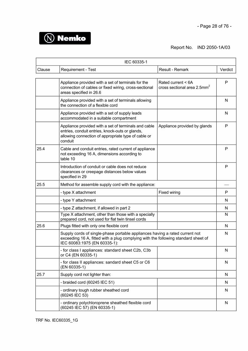
Appliance provided with a set of terminals for theconnection of cables or fixed wiring, cross-sectionalareas specified in 26.6
Rated current < 6A cross sectional area 2.5mm2
P
Appliance provided with a set of terminals allowingthe connection of a flexible cord
N
Appliance provided with a set of supply leadsaccommodated in a suitable compartment
N
Appliance provided with a set of terminals and cableentries, conduit entries, knock-outs or glands,allowing connection of appropriate type of cable orconduit
Appliance provided by glands P
25.4 Cable and conduit entries, rated current of appliancenot exceeding 16 A, dimensions according totable 10
P
Introduction of conduit or cable does not reduceclearances or creepage distances below valuesspecified in 29
P
25.5 Method for assemble supply cord with the appliance:
- type X attachment Fixed wiring P
- type Y attachment N
- type Z attachment, if allowed in part 2 NType X attachment, other than those with a speciallyprepared cord, not used for flat twin tinsel cords
N
25.6 Plugs fitted with only one flexible cord N
Supply cords of single-phase portable appliances having a rated current notexceeding 16 A, fitted with a plug complying with the following standard sheet ofIEC 60083:1975 (EN 60335-1):
N
- for class I appliances: standard sheet C2b, C3bor C4 (EN 60335-1)
N
- for class II appliances: sandard sheet C5 or C6(EN 60335-1)
N
25.7 Supply cord not lighter than: N
- braided cord (60245 IEC 51) N
- ordinary tough rubber sheathed cord(60245 IEC 53)
N
- ordinary polychloroprene sheathed flexible cord(60245 IEC 57) (EN 60335-1)
N

- Page 29 of 76 -
Report No. IND 2050-1A/03
IEC 60335-1
Clause Requirement - Test Result - Remark Verdict
TRF No. IEC60335_1G
- flat twin tinsel cord (60227 IEC 41) N
- light polyvinyl chloride sheathed cord(60227 IEC 52), appliance not exceeding 3 kg
N
- ordinary polyvinyl chloride sheathed cord(60227 IEC 53), appliance exceeding 3 kg
N
When used supply cords having high flexibility, they are not lighter than(EN 60335-1):
- rubber insulated and sheathed cord(60245 IEC 86)
N
- rubber insulated, crosslinked PVC sheathed cord(60245 IEC 87)
N
- crosslinked PVC insulated and sheathed cord(60245 IEC 88)
N
Temperature rise of external metal parts exceeding75 K, PVC cord not used, unless
N
appliance so constructed that the supply cord is notlikely to touch external metal parts in normal use, or
N
the supply cord is appropriate for highertemperatures, type Y or type Z attachment used
N
25.8 Nominal cross-sectional area of supply cordsaccording to table 11; rated current (A); cross-sectional area (mm²)................................................ :
N
25.9 Supply cord not in contact with sharp points or edges P
25.10 Green/yellow core for earthing purposes in Class Iappliance
P
25.11 Conductors of supply cords not consolidated bylead-tin soldering where they are subject to contactpressure, unless
N
clamping means so constructed that there is no riskof bad contacts due to cold flow of the solder
N
25.12 Moulding the cord to part of the enclosure does notdamage the insulation of the supply cord
N
25.13 Inlet opening so shaped as to prevent damage to thesupply cord
Appliance provided by inletbushing
P

- Page 30 of 76 -
Report No. IND 2050-1A/03
IEC 60335-1
Clause Requirement - Test Result - Remark Verdict
TRF No. IEC60335_1G
Unless the enclosure at the inlet opening is ofinsulation material, a non-detachable lining orbushing complying with 29.3 for supplementaryinsulation provided
N
If unsheathed supply cord, a similar additionalbushing or lining is required, unless
N
the appliance is class 0 N
25.14 Supply cords adequately protected againstexcessive flexing
Appliance sold without supplycord
N
Flexing test: __
- applied force (N) .................................................... : N
- number of flexings ................................................. : N
The test does not result in: N
- short circuit between the conductors N
- breakage of more than 10% of the strands of anyconductor
N
- separation of the conductor from its terminal N
- loosening of any cord guard N
- damage, within the meaning of the standard, to thecord or the cord guard
N
- broken strands piercing the insulation andbecoming accessible
N
25.15 Conductors of the supply cord relieved from strain,twisting and abrasion by use of cord anchorage
N
The cord cannot be pushed into the appliance tosuch an extent that the cord or internal parts of theappliance can be damaged
N
Pull and torque test of supply cord, values shown intable 10: pull (N); torque (not on automatic cord reel)(Nm) ......................................................................... :
N
Max. 2 mm displacement of the cord, andconductors not moved more than 1 mm in theterminals
N
Creepage distances and clearances not reducedbelow values specified in 29.1
N

- Page 31 of 76 -
Report No. IND 2050-1A/03
IEC 60335-1
Clause Requirement - Test Result - Remark Verdict
TRF No. IEC60335_1G
25.16 Cord anchorages for type X attachments constructed and located so that: __
- replacement of the cord is easily possible N
- it is clear how the relief from strain and theprevention of twisting are obtained
N
- they are suitable for different types of cord N
- cord cannot touch the clamping screws of cordanchorage if these screws are accessible, unlessseparated from accessible metal parts bysupplementary insulation
N
- the cord is not clamped by a metal screw whichbears directly on the cord
N
- at least one part of the cord anchorage securelyfixed to the appliance, unless part of a speciallyprepared cord
N
- screws which have to be operated when replacingthe cord do not fix any other component, if applicable
N
- if labyrinths can be bypassed the test of 25.15 isnevertheless withstood
N
- for Class 0, 0I and I appliances: they are ofinsulating material or are provided with an insulatinglining, unless a failure of the insulation of the corddoes not make accessible metal parts live
N
- for Class II appliances: they are of insulatingmaterial, or if of metal, they are insulated fromaccessible metal parts by supplementary insulation
N
25.17 Adequate cord anchorages for type Y and Zattachment
N
25.18 Cord anchorages only accessible with the aid of atool, or
N
so constructed that the cord can only be fitted withthe aid of a tool
N
25.19 Type X attachment, glands not used as cordanchorage in portable appliances
Not a portable appliance N
Tying the cord into a knot or tying the cord with stringnot used
N
25.20 Conductors of the supply cord for type Y and Zattachment adequately additionally insulated
N

- Page 32 of 76 -
Report No. IND 2050-1A/03
IEC 60335-1
Clause Requirement - Test Result - Remark Verdict
TRF No. IEC60335_1G
25.21 Space for supply cord for type X attachment or forconnection of fixed wiring constructed to permitchecking of conductors with respect to correctpositioning and connection before fitting any cover,no risk of damage to the conductors when fitting thecover, no contact with accessible metal parts if aconductor becomes loose, etc.
P
For portable appliances, the uninsulated end of aconductor prevented from any contact withaccessible metal parts, unless the end of the cord issuch that the conductors are unlikely to slip free
Not a portable appliance N
25.22 Appliance inlet:
- live parts not accessible during insertion or removal N
- connector can be inserted without difficulty N
- the appliance is not supported by the connector N
- is not for cold conditions if temp. rise of externalmetal parts exceeds 75 K, unless the supply cord isnot likely to touch such metal parts
N
25.23 Interconnection cords comply with the requirementsfor the supply cord, except as specified
Wire to motor :Rated current 3.5ARequired 1mm2
Cross sectional area 1.5mm2
P
If necessary, electric strength test of 16.3 N
25.24 Interconnection cords not detachable without the aidof a tool if compliance with the standard is impairedwhen they are disconnected
A screwdriver is necessary toremove the enclosure (all theinterconnection wire arebeneath the plastic cover)
P
25.25 Dimensions of pins compatible with the dimensionsof the relevant socket-outlet. Dimensions of pins andengagement face in accordance with the relevantplug in IEC 60083
N
26 TERMINALS FOR EXTERNAL CONDUCTORS
26.1 Appliances provided with terminals or equallyeffective devices for connection of externalconductors
Approved terminal block used P
Terminals only accessible after removal of a non-detachable cover
Removal of the cover with ascrewdriver
P

- Page 33 of 76 -
Report No. IND 2050-1A/03
IEC 60335-1
Clause Requirement - Test Result - Remark Verdict
TRF No. IEC60335_1G
26.2 Appliances with type X attachment and appliancesfor connection to fixed wiring provided with terminalsin which connections are made by means of screws,nuts or similar devices, unless the connections aresoldered
Terminal block with screws P
Screws and nuts serve only to clamp supplyconductors, except
P
internal conductors, if so arranged that they areunlikely to be displaced when fitting the supplyconductors
Connected to separatedterminal block
P
If soldered connections used, the conductor sopositioned or fixed that reliance is not placed onsoldering alone
N
Soldering alone used, barriers provided, clearancesand creepage distances satisfactory if the conductorbecomes free at the soldered joint
N
26.3 Terminals for type X attachment and for connectionto fixed wiring so constructed that the conductor isclamped between metal surfaces with sufficientcontact pressure and without damaging theconductor
Terminal blocks are approvedcomponents
P
Terminals for type X attachment and those for connection to fixed wiring so fixed thatwhen tightening or loosening the clamping means:
P
- the terminal does not loosen P
- internal wiring is not subjected to stress P
- clearances and creepage distances are notreduced below the values in 29
P
Compliance checked by inspection and by the test ofsubclause 8.6 of IEC 60999-1, the torque appliedbeing equal to two-thirds of the torque specified.Nominal diameter of thread (mm); screw category;torque (Nm).............................................................. :
Approved components P
26.4 Terminals for type X attachment, except those with aspecially prepared cord, and those for connection tofixed wiring, no special preparation of conductorsrequired, and so constructed or placed thatconductors prevented from slipping out
P

- Page 34 of 76 -
Report No. IND 2050-1A/03
IEC 60335-1
Clause Requirement - Test Result - Remark Verdict
TRF No. IEC60335_1G
26.5 Terminals for type X attachment so located orshielded that if a wire of a stranded conductorescapes, no risk of accidental connection to otherparts that result in a hazard
N
Stranded conductor test, 8 mm insulation removed N
No contact between live parts and accessible metalparts and, for class II constructions, between liveparts and metal parts separated from accessiblemetal parts by supplementary insulation only
N
26.6 Terminals for type X attachment and for connectionto fixed wiring suitable for connection of conductorswith required cross-sectional area according totable 13; rated current (A); nominal cross-sectionalarea (mm²) ............................................................... :
Rated current <6A
Cross sectional area 2.5mm²
P
Terminals only suitable for a specially prepared cord N
26.7 Terminals for type X attachment accessible afterremoval of a cover or part of the enclosure
Removal of the cover P
26.8 Terminals for the connection to fixed wiring, includingthe earthing terminal, located close to each other
P
26.9 Terminals of the pillar type constructed and locatedas specified
N
26.10 Terminals with screw clamping and screwlessterminals not used for flat twin tinsel cords, unlessconductors ends fitted with a device suitable forscrew terminals
N
Pull test of 5 N to the connection N
26.11 For type Y and Z attachment: soldered, welded,crimped and similar connections may be used
N
For Class II appliances: the conductor so positionedor fixed that reliance is not placed on soldering,welding or crimping alone
N
For Class II appliances: soldering, welding orcrimping alone used, barriers provided, clearancesand creepage distances satisfactory if the conductorbecomes free
N
27 PROVISION FOR EARTHING

- Page 35 of 76 -
Report No. IND 2050-1A/03
IEC 60335-1
Clause Requirement - Test Result - Remark Verdict
TRF No. IEC60335_1G
27.1 Accessible metal parts of Class 0I and I appliances,permanently and reliably connected to an earthingterminal or contact of the appliance inlet
P
Earthing terminals not connected to neutral terminal P
Class 0, II and III appliance have no provision forearthing
Class I appliance N
Safety extra-low voltage circuits not earthed, unlessprotective extra-low voltage circuits
Not earthed P
27.2 Clamping means adequately secured againstaccidental loosening
Terminal approved P
Terminals used for the connection of externalequipotential bonding conductors allow connection ofconductors of 2.5 to 6 mm², and
No equipotential bonding N
do not provide earthing continuity between differentparts of the appliance
N
Conductors cannot be loosened without the aid of atool
P
27.3 For appliances with supply cord, current-carryingconductors become taut before earthing conductor, ifthe cord slips out of the cord anchorage
Supplied without supply cord N
27.4 No risk of corrosion resulting from contact betweenmetal of earthing terminal and other metal
P
Adequate resistance to corrosion of coated oruncoated parts providing earthing continuity, otherthan parts of a metal frame or enclosure
Provision for earthing fixed byscrew ∅3mm and lock washerto the metal frame
P
Parts of steel providing earthing continuity providedat the essential areas with an electroplated coating,thickness at least 5 µm
N
Adequate protection against rusting of parts ofcoated or uncoated steel, only intended to provide ortransmit contact pressure
P
27.5 Low resistance of connection between earthingterminal and earthed metal parts
P
This requirement does not apply to connectionsproviding earthing continuity in the protective extra-low voltage circuit, provided that clearances of basicinsulation are based on the rated voltage of theappliance
N

- Page 36 of 76 -
Report No. IND 2050-1A/03
IEC 60335-1
Clause Requirement - Test Result - Remark Verdict
TRF No. IEC60335_1G
Resistance not exceeding 0,1 Ω at the specified low-resistance test
Meas. between the earthingterminal and:earthed metal part motor0.025 Ωmetallic part of the enclosure0.015 Ω
P
27.6 The printed conductors of printed circuit boards notused to provide earthing continuity in hand heldappliances
Not hand held appliance N
They may be used in other appliances if:
- at least two tracks are used with independentsoldering points and the appliance complies withrequirements of 27.5 for each circuit
N
- the material of the printed circuit board complieswith IEC 60249-2-4 or IEC 60249-2-5
N
28 SCREWS AND CONNECTIONS
28.1 Fixings, electrical connections and connectionsproviding earthing continuity withstand mechanicalstresses
P
Screws not of soft metal liable to creep, such as zincor aluminium
No screws of soft metal P
Diameter of screws of insulating material min. 3 mm No screws of insulationmaterial
N
Screws of insulating material not used for anyelectrical connection or connections providingearthing continuity
Not used P
Screws used for electrical connections orconnections providing earthing continuity screw intometal
Provision for earthing continuityfixed by screw ∅3mm and lockwasher to the metal frame
P
Screws not of insulating material if their replacementby a metal screw can impair supplementary orreinforced insulation
N
Type X attachment, screws to be removed forreplacement of supply cord or for user maintenance,not of insulating material if their replacement by ametal screw can impair basic insulation
N
For screws and nuts; test as specified (see appended table) N

- Page 37 of 76 -
Report No. IND 2050-1A/03
IEC 60335-1
Clause Requirement - Test Result - Remark Verdict
TRF No. IEC60335_1G
28.2 Electrical connections and connections providingearthing continuity constructed so that contactpressure not transmitted through insulating materialliable to shrink or distort, unless shrinkage ordistortion compensated
Provision for earthing continuityfixed by screw ∅3mm and lockwasher to the metal frame
P
This requirement does not apply to electricalconnections in circuits carrying a current notexceeding 0.5A
N
28.3 Space-threaded (sheet metal) screws only used forelectrical connections if they clamp the partstogether
N
Thread-cutting (self-tapping) screws only used forelectrical connections if they generate a full formstandard machine screw thread
Not used N
Such screws not used if they are likely to beoperated by the user or installer unless the thread isformed by a swaging action
N
Thread-cutting and space-threaded screws may beused in connections providing earthing continuity,provided unnecessary to disturb the connection andat least two screws are used for each connection
N
28.4 Screws and nuts that make mechanical connectionsecured against loosening if they also makeelectrical connections or connections providingearthing continuity
N
Rivets for electrical connections or connectionsproviding earthing continuity secured againstloosening if subjected to torsion
N
29 CLEARANCES, CREEPAGE DISTANCES AND SOLID INSULATION
Clearances, creepage distances and solid insulationwithstand electrical stress
P
For coatings used on printed circuits boards toprotect the microenvironment or to provide basicinsulation, annex J applies
Component approved (seecomponent list)
P
29.1 Clearances not less than the values specified intable 16, taking into account the rated impulsevoltage for the overvoltage categories of table 15
Overvoltage cat IIRated impulse 2500Vmin clearance required 2mmmeasured 3mm
P

- Page 38 of 76 -
Report No. IND 2050-1A/03
IEC 60335-1
Clause Requirement - Test Result - Remark Verdict
TRF No. IEC60335_1G
The values specified may be smaller for basicinsulation and functional insulation if the clearancemeets the impulse voltage test of clause 14
N
Appliances are in overvoltage category II P
Clearances less than specified in table 16 notallowed for basic insulation of class 0 and class 0Iappliances,
N
or if pollution degree 3 is applicable N
Compliance is checked by inspection andmeasurements as specified
P
29.1.1 Clearances of basic insulation withstand theovervoltages, taking into account the rated impulsevoltage
P
Clearance at the terminals of tubular sheathedheating elements may be reduced to 1mm if themicroenvironment is pollution degree 1
N
Lacquered conductors of windings assumed to bebare conductors, but the clearances specified intable 16 are reduced by 0.5mm for rated impulsevoltages of at least 1500V
N
29.1.2 Clearances of supplementary insulation not less thanthose specified for basic insulation in table 16
P
29.1.3 Clearances of reinforced insulation not less thanthose specified for basic insulation in table 16, butusing the next higher step for rated impulse voltage
Insulation transformer tested inthe equipment
P
29.1.4 For functional insulation, the values of table 16 areapplicable, unless
N
the appliance complies with clause 19 with thefunctional insulation short-circuited
N
Clearances at crossover points of lacqueredconductors not measured
N
Clearance between surfaces of PTC heatingelements may be reduced to 1mm
N
Lacquered conductors of windings assumed to bebare conductors, but the clearances specified intable 16 are reduced by 0.5mm for rated impulsevoltages of at least 1500V
N

- Page 39 of 76 -
Report No. IND 2050-1A/03
IEC 60335-1
Clause Requirement - Test Result - Remark Verdict
TRF No. IEC60335_1G
29.1.5 Appliances having higher working voltage than ratedvoltage, the voltage used for determining clearancesfrom table 16 is the sum of the rated impulse voltageand the difference between the peak value of theworking voltage and the peak value of the ratedvoltage
N
If the secondary winding of a step-down transformeris earthed, or if there is an earthed screen betweenthe primary and secondary windings, clearances ofbasic insulation on the secondary side not less thanthose specified in table 16, but using the next lowerstep for rated impulse voltage
Secondary winding of stepdown transformer not earthed
N
Circuits supplied with a voltage lower than ratedvoltage, clearances of functional insulation based onthe working voltage used as the rated voltage intable 15
N
29.2 Creepage distances not less than those appropriatefor the working voltage, taking into account thematerial group and the pollution degree
Material group IIMinimum creepage on live partof the circuit measured 2.7mmRequired 1.8mm
P
Pollution degree 2 applies, unless Pollution degree 2 P
precautions taken to protect the insulation; pollutiondegree 1
N
insulation subjected to conductive pollution; pollutiondegree 3
N
Compliance is checked by inspection andmeasurements as specified
P
29.2.1 Creepage distances of basic insulation not less thanspecified in table 17
Overvoltage cat IIPollution degree IIRated impulse 2500Vmin creepage 1.8mmmeasured 2.7mm
P
For pollution degree 1, creepage distance not lessthan the minimum specified for the clearance in table16, if the clearance has been checked according tothe test of clause 14
N
29.2.2 Creepage distances of supplementary insulation atleast as specified for basic insulation in table 17
P
29.2.3 Creepage distances of reinforced insulation at leastdouble as specified for basic insulation in table 17
N

- Page 40 of 76 -
Report No. IND 2050-1A/03
IEC 60335-1
Clause Requirement - Test Result - Remark Verdict
TRF No. IEC60335_1G
29.2.4 Creepage distances of functional insulation not lessthan specified in table 18
N
Creepage distances may be reduced if the appliancecomplies with clause 19 with the functional insulationshort-circuited
N
29.3 Solid insulation having a minimum thickness of 1mmfor supplementary insulation,
N
and 2mm for reinforced insulation N
This requirement does not apply if thesupplementary insulation, other than mica or similarscaly material, consists of at least two layers, each ofthe layers withstands the electric strength test of 16.3
N
This requirement does not apply if the reinforcedinsulation, other than mica or similar scaly material,consists of at least three layers, any two layerstogether withstand the electric strength test of 16.3
N
This requirement also does not apply to inaccessibleinsulation and does not exceed the maximumpermissible temperature values, or
N
if the insulation, after conditioning as specified,withstands the electric strength test of 16.3
N
30 RESISTANCE TO HEAT AND FIRE
30.1 External parts of non-metallic material, 75°C Plastic parts tested P
parts supporting live parts, and 125°C Supporting live part P
thermoplastic material providing supplementary orreinforced insulation,
N
sufficiently resistant to heat P
Ball-pressure test according to IEC 60695-10-2 Deformation 1.3mm P
External parts: at 40 °C plus the maximumtemperature rise determined during the test of clause11, or at 75 °C, whichever is the higher; temperature(°C)........................................................................... :
Plastic parts tested at 75°C P
Parts supporting live parts: at 40°C plus themaximum temperature rise determined during thetest of clause 11, or at 125°C, whichever is thehigher; temperature (°C).......................................... :
PCB and Terminal blockcomponent approved (seecomponent list)Terminal block tested at 125°C
P

- Page 41 of 76 -
Report No. IND 2050-1A/03
IEC 60335-1
Clause Requirement - Test Result - Remark Verdict
TRF No. IEC60335_1G
Parts of thermoplastic material providingsupplementary or reinforced insulation, 25°C plusthe maximum temperature rise determined duringclause 19, if higher; temperature (°C) ..................... :
N
30.2 Relevant parts of non-metallic material adequatelyresistant to ignition and spread of fire
External parts of non metallicmaterial are UL 94V-0
P
30.2.1 Glow-wire test of IEC 60695-2-11 at 550 °C, unless Enclosure plastic material P
the material is classified at least HB40 according toIEC 60695-11-10
N
Parts for which the glow-wire test cannot be carriedout meet the requirements in ISO9772 for categoryFH3 material
N
30.2.2 Appliances operated while attended, parts of insulating material supporting current-carrying connections and parts within a distance of 3mm subjected to the glow-wiretest of IEC 60695-2-11 at a temperature of:
N
-750°C, for connections carrying a current exceeding0,5A during normal operation
N
-650°C, for other connections N
Test not applicable to conditions as specified N
30.2.3 Appliances operated while unattended, tested asspecified in 30.2.3.1 and 30.2.3.2
P
Test not applicable to conditions as specified N
30.2.3.1 Parts of insulating material supporting connectionscarrying a current exceeding 0.2A during normaloperation, and
P
parts of insulating material within a distance of 3mm, PCB, P
having a glow-wire flammability index of at least850°C according to IEC 60695-2-12
PCB (UL 94V-0 approved) P
30.2.3.2 Parts of insulating material supporting current-carrying connections, and
Terminal block approved
PCB approved component
P
parts of insulating material within a distance of 3mm, Insulating foam between PCBand metal sustain.
P
subjected to glow-wire test of IEC 60695-2-11 P
Test not carried out on material having a glow-wireignition temperature according to IEC 60695-2-13 asspecified
N

- Page 42 of 76 -
Report No. IND 2050-1A/03
IEC 60335-1
Clause Requirement - Test Result - Remark Verdict
TRF No. IEC60335_1G
Glow-wire test of IEC 60695-2-11, the temperature being: N
-750°C, for connections carrying a current exceeding0,2A during normal operation
P
-650°C, for other connections P
Parts that during the test produce a flame persistinglonger than 2 s, tested as specified
N
If a flame persists longer than 2 s during the test,parts above the connection, as specified, subjectedto the needle-flame test of annex E, unless
N
the material is classified as V-0 or V-1 according toIEC 60695-11-10
PCB classified V0 P
30.2.4 Base material of printed circuit boards subjected toneedle-flame test of annex E
PCB approved (seecomponent list)
P
Test not applicable to conditions as specified Classified V0 P
31 RESISTANCE TO RUSTING
Relevant ferrous parts adequately protected againstrusting
Salt mist test performed P
32 RADIATION, TOXICITY AND SIMILAR HAZARDS
Appliance does not emit harmful radiation P
Appliance does not present a toxic or similar hazard P
A ANNEX A (INFORMATIVE)ROUTINE TESTS
Description of routine tests to be carried out by themanufacturer
P
B ANNEX B (NORMATIVE)APPLIANCES POWERED BY RECHARGEABLE BATTERIES
N
The following modifications to this standard areapplicable for appliances powered by batteries thatare recharged in the appliance
No batteries N
This annex does not apply to battery chargers N
3.1.9 Appliance operated under the following conditions: N
-the appliance, supplied by its fully charged battery,operated as specified in relevant part 2
N

- Page 43 of 76 -
Report No. IND 2050-1A/03
IEC 60335-1
Clause Requirement - Test Result - Remark Verdict
TRF No. IEC60335_1G
-the battery is charged, the battery being initiallydischarged to such an extent that the appliancecannot operate
N
-if possible, the appliance is supplied from the supplymains through its battery charger, the battery beinginitially discharged to such an extent that theappliance cannot operate. The appliance is operatedas specified in relevant part 2
N
If the appliance incorporates inductive couplingbetween two parts that are detachable from eachother, the appliance is supplied from the supplymains with the detachable part removed
N
3.6.2 Part to be removed in order to discard the battery isnot considered to be detachable
N
5.101 Appliances supplied from the supply mains tested asspecified for motor-operated appliances
N
7.1 Battery compartment for batteries intended to bereplaced by the user, marked with battery voltageand polarity of the terminals
N
7.12 The instructions for appliances incorporatingbatteries intended to be replaced by the userincludes required information
N
Details about how to remove batteries containingmaterials hazardous to the environment given
N
7.15 Markings placed on the part of the applianceconnected to the supply mains
N
8.2 Appliances having batteries that according to theinstruction may be replaced by the user need onlyhave basic insulation between live parts and theinner surface of the battery compartment
N
If the appliance can be operated without batteries,double or reinforced insulation required
N
11.7 The battery is charged for the period described N
19.1 Appliances subjected to tests of 19.101, 19.102 and19.103
N
19.101 Appliances supplied at rated voltage for 168 h, thebattery being continually charged
N

- Page 44 of 76 -
Report No. IND 2050-1A/03
IEC 60335-1
Clause Requirement - Test Result - Remark Verdict
TRF No. IEC60335_1G
19.102 Short-circuiting of the terminals of the battery, beingfully charged, for appliances having batteries thatcan be removed without the aid of a tool
N
19.103 Appliances having batteries replaceable by the usersupplied at rated voltage under normal operationwith the battery removed or in any position allowedby the construction
N
21.101 Appliances having pins for insertion into socket-outlets have adequate mechanical strength, checkedaccording to procedure 2 of IEC 68-2-32
N
Part of the appliance incorporating the pins subjected to the free fall test, procedure 2,of IEC 60068-2-32, the number of falls being:
__
- 100, the mass of part does not exceed 250 g N
- 50, the mass of part exceeds 250 g N
After the test, the requirements of 8.1, 15.1.1, 16.3and clause 29 are met
N
22.3 Appliances having pins for insertion into socket-outlets tested as fully assembled as possible
N
25.13 An additional lining or bushing not required forinterconnection cords operating at safety extra-lowvoltage
N
30.2 For parts of the appliance connected to the supplymains during the charging period, 30.2.3 applies
N
For other parts, 30.2.2 applies N
C ANNEX C (NORMATIVE)AGEING TEST ON MOTORS
N
Tests, as described, carried out when doubt withregard to the temperature classification of theinsulation of a motor winding
N
D ANNEX D (NORMATIVE)ALTERNATIVE REQUIREMENTS FOR PROTECTED MOTORS
N
Applicable to protected motors for unattended use,test of 19.7 carried out on a separate sampleaccording to the specification
N
E ANNEX E (NORMATIVE)NEEDLE-FLAME TEST

- Page 45 of 76 -
Report No. IND 2050-1A/03
IEC 60335-1
Clause Requirement - Test Result - Remark Verdict
TRF No. IEC60335_1G
Needle-flame test carried out in accordance withIEC 60695-2-2, with the following modifications:
P
5 Severities P
The duration of application of the test flame is30 s ± 1 s
P
8 Test procedure P
8.2 The specimen so arranged that the flame can beapplied to a vertical or horizontal edge as shown inthe examples of figure 1
P
8.4 The first paragraph does not apply Considered P
If possible, the flame is applied at least 10 mm froma corner
P
8.5 The test is carried out on one specimen P
If the specimen does not withstand the test, the testmay be repeated on two further specimens, bothwithstanding the test
First specimen withstand thetest
N
10 Evaluation of test results
The duration of burning not exceeding 30 s Burning < 7s P
However, for printed circuit boards, the duration ofburning not exceeding 15 s
PCB not tested (approvedcomponent)
N
F ANNEX F (NORMATIVE)CAPACITORS
Capacitors likely to be permanently subjected to thesupply voltage, and used for radio interferencesuppression or voltage dividing, comply with thefollowing clauses of IEC 60384-14, with the followingmodifications:
C1,C2 are approvedcomponents
P
1.5 Terminology __
1.5.3 Class X capacitors tested according to subclass X2 __
1.5.4 This subclause is applicable __
1.6 Marking __
Items a) and b) are applicable __
3.4 Approval testing __
3.4.3.2 Table II is applicable as described __

- Page 46 of 76 -
Report No. IND 2050-1A/03
IEC 60335-1
Clause Requirement - Test Result - Remark Verdict
TRF No. IEC60335_1G
4.1 Visual examination and check of dimensions __
This subclause is applicable __
4.2 Electrical tests __
4.2.1 This subclause is applicable __
4.2.5 This subclause is applicable __
4.2.5.2 Only table IX is applicable __
Values for test A apply __
However, for capacitors in heating appliances thevalues for test B or C apply
__
4.12 Damp heat, steady state __
This subclause is applicable __
Only insulation resistance and voltage proof arechecked
__
4.13 Impulse voltage __
This subclause is applicable __
4.14 Endurance __
Subclauses 4.14.1, 4.14.3, 4.14.4 and 4.14.7applicable
__
4.14.7 Only insulation resistance and voltage proof arechecked
__
Visual examination, no visible damage __
4.17 Passive flammability test __
This subclause is applicable __
4.18 Active flammability test __
This subclause is applicable __
G ANNEX G (NORMATIVE)SAFETY ISOLATING TRANSFORMERS
The following modifications to this standard areapplicable for safety isolating transformers:
P
7 Marking and instructions P
7.1 Transformers for specific use marked with: P

- Page 47 of 76 -
Report No. IND 2050-1A/03
IEC 60335-1
Clause Requirement - Test Result - Remark Verdict
TRF No. IEC60335_1G
-name, trademark or identification mark of themanufacturer or responsible vendor
See component list P
-model or type reference See component list P
17 Overload protection of transformers and associated circuits N
Fail-safe transformers comply with subclause 15.5 ofIEC 61558-1
N
22 Construction __
Subclauses 19.1 and 19.1.2 of IEC 61558-2-6 areapplicable
P
29 Clearances, creepage distances and solid insulation __
29.1 and29.2
The distances specified in items 2a, 2c and 3 in table13 of IEC 61558-1 apply
Conventional sealedtransformer with two bobbinseparate. Approvedcomponentrequired 1mm
P
H ANNEX H (NORMATIVE)SWITCHES
Switches comply with the following clauses of IEC 61058-1, as modified: N
-The tests of IEC 61058-1 carried out under theconditions occurring in the appliance
No mains switch N
-Before being tested, switches are operated 20 timeswithout load
N
8 Marking and documentation N
Switches are not required to be marked N
However, switches that can be tested separatelyfrom the appliance marked with the manufacturer’sname or trade mark and the type reference
N
13 Mechanism N
The tests may be carried out on a separate sample N
15 Insulation resistance and dielectric strength N
15.1 Not applicable N
15.2 Not applicable N
15.3 Applicable for full disconnection and micro-disconnection
N

- Page 48 of 76 -
Report No. IND 2050-1A/03
IEC 60335-1
Clause Requirement - Test Result - Remark Verdict
TRF No. IEC60335_1G
17 Endurance N
Compliance is checked on three separate appliancesor switches
N
For 17.2.4.4, the number of cycles is 10 000, unlessotherwise specified in 24.1.3 of the relevant part 2 ofIEC 60335
N
Switches for operation under no load and which canbe operated only by a tool and switches operated byhand that are interlocked so that they cannot beoperated under load, are not subjected to the tests
N
Subclause 17.2.5.2 is not applicable N
Temperature rise of the terminals not more than 30 Kabove the temperature rise measured in clause 11 ofIEC 60335-1
N
20 Clearances, creepage distances, solid insulation and coatings of rigid printed boardassemblies
N
This clause is applicable to clearances and creepagedistances for functional insulation, across fulldisconnection and micro-disconnection, as stated intable 24
N
I ANNEX I (NORMATIVE)MOTORS HAVING BASIC INSULATION THAT IS INADEQUATE FOR THE RATEDVOLTAGE OF THE APPLIANCE
The following modifications to this standard areapplicable for motors having basic insulation that isinadequate for the rated voltage of the appliance:
N
8 Protection against access to live parts N
8.1 Metal parts of the motor are considered to be barelive parts
N
11 Heating N
11.3 Temperature rise of the body of the motor isdetermined instead of the temperature rise of thewindings
N
11.8 Temperature rise of the body of the motor, where incontact with insulating material, not exceedingvalues in table 3 for the relevant insulating material
N
16 Leakage current and electric strength N

- Page 49 of 76 -
Report No. IND 2050-1A/03
IEC 60335-1
Clause Requirement - Test Result - Remark Verdict
TRF No. IEC60335_1G
16.3 Insulation between live parts of the motor and itsother metal parts not subjected to the test
N
19 Abnormal operation N
19.1 The tests of 19.7 to 19.9 not carried out N
19.101 Appliance operated at rated voltage with each of the following fault conditions: N
- short circuit of the terminals of the motor, includingany capacitor incorporated in the motor circuit
N
- short circuit of each diode of the rectifier N
- open circuit of the supply to the motor N
- open circuit of any parallel resistor, the motor beingin operation
N
Only one fault simulated at a time, the tests carriedout consecutively
N
22 Construction N
22.101 For class I appliances incorporating a motor suppliedby a rectifier circuit, the d.c. circuit being insulatedfrom accessible parts of the appliance by double orreinforced insulation
N
Compliance checked by the tests specified fordouble and reinforced insulation
N
J ANNEX J (NORMATIVE)COATED PRINTED CIRCUIT BOARDS
Testing of protective coatings of printed circuitboards carried out in accordance with IEC 60664-3with the following modifications:
Approved component __
6.6 Climatic sequence __
When production samples are used, three samplesof the printed circuit board are tested
__
6.6.1 Cold __
The test is carried out at -25°C __
6.6.3 Rapid change of temperature __
Severity 1 is specified __
6.8.6 Partial discharge extinction voltage __

- Page 50 of 76 -
Report No. IND 2050-1A/03
IEC 60335-1
Clause Requirement - Test Result - Remark Verdict
TRF No. IEC60335_1G
Type A coatings not subjected to a partial dischargetest
__
6.9 Additional tests __
This subclause is not applicable __
K ANNEX K (NORMATIVE)OVERVOLTAGE CATEGORIES
The information on overvoltage categories isextracted from IEC 60664-1
Considered __
Overvoltage category is a numeral defining atransient overvoltage condition
Considered __
Equipment of overvoltage category IV is for use atthe origin of the installation
N
Equipment of overvoltage category III is equipmentin fixed installations and for cases where thereliability and the availability of the equipment issubject to special requirements
N
Equipment of overvoltage category II is energyconsuming equipment to be supplied from the fixedinstallation
P
If such equipment is subjected to specialrequirements with regard to reliability and availability,overvoltage category III applies
N
Equipment of overvoltage category I is equipment forconnection to circuits in which measures are taken tolimit transient overvoltages to an appropriate lowlevel
N
L ANNEX L (INFORMATIVE)GUIDANCE FOR THE MEASUREMENT OF CLEARANCES AND CREEPAGEDISTANCES

- Page 51 of 76 -
Report No. IND 2050-1A/03
IEC 60335-1
Clause Requirement - Test Result - Remark Verdict
TRF No. IEC60335_1G
Sequences for the determination of clearances andcreepage distances
Rated voltage 230Vac,
Overvoltage category II
Pollution degree 2
Appliance class I
Rated impulse voltage<2500Vac
Minimum clearance 2.0mm
Minimum creepage distance1.8mm
P
M ANNEX M (NORMATIVE)POLLUTION DEGREE
The information on pollution degrees is extractedfrom IEC 60664-1
Considered __
Pollution __
The microenvironment determines the effect ofpollution on the insulation, taking into account themicroenvironment
P
Means may be provided to reduce pollution at theinsulation by effective enclosures or similar
IP 54 not reduce pollution N
Minimum clearances specified where pollution maybe present in the microenvironment
P
Degrees of pollution in the microenvironment P
For evaluating creepage distances, the following degrees of pollution in themicroenvironment are established:
P
- pollution degree 1: no pollution or only dry, non-conductive pollution occurs. The pollution has noinfluence
N
- pollution degree 2: only non-conductive pollutionoccurs, except that occasionally a temporaryconductivity caused by condensation is to beexpected
P
- pollution degree 3: conductive pollution occurs ordry non-conductive pollution occurs that becomesconductive due to condensation that is to beexpected
N

- Page 52 of 76 -
Report No. IND 2050-1A/03
IEC 60335-1
Clause Requirement - Test Result - Remark Verdict
TRF No. IEC60335_1G
- pollution degree 4: the pollution generatespersistent conductivity caused by conductive dust orby rain or snow
N
N ANNEX N (NORMATIVE)PROOF TRACKING TEST
The proof tracking test is carried out in accordancewith IEC 60112 with the following modifications:
CTI provided by manufacturer
(material group II)
N
5 Test apparatus __
5.1 Electrodes __
The note does not apply __
5.4 Test solutions __
Test solution A is used __
6 Procedure __
6.3 Proof tracking test __
Voltage is 100V, 175V, 400V or 600V .................... : __
Note 3 of clause 3 applies __
The test is carried out on five specimens __
In case of doubt, additional test with voltage reducedby 25V, the number of drops increased to 100
__
7 Report __
The report stating if the PTI value was based on atest using 100 drops with a test voltage of (PTI-25) V
__
O ANNEX O (INFORMATIVE)SELECTION AND SEQUENCE OF THE TESTS OF CLAUSE 30
Description of tests for determination of resistance toheat and fire
Considered P

- Page 53 of 76 -
Report No. IND 2050-1A/03
IEC 60335-1
Clause Requirement - Test Result - Remark Verdict
TRF No. IEC60335_1G
ZA ANNEX ZA (NORMATIVE)SPECIAL NATIONAL CONDITIONS (EN 60335-1)
7.12 DENMARK: Supply cords of class I appliances,which are delivered without a plug, shall beprovided with a visible tag with the following text:Vigtigt! Lederen med grøn/gul isolation må kuntilsluttes en klemme mærketImportant! The conductor having green/yellowinsulation shall only be connected to a terminalmarked
(IEC 417, No. 5019 eller/or IEC 417, No. 5017)."If it is essential for the safety of the appliance, thetag shall be provided with a diagram showing theconnection of the other conductors or with thefollowing text:"For tilslutning af de øvrige ledere, se medfølgendeinstallationsvejledning.For the connection of the other conductors, see theenclosed instructions for installation.
Fixed wiring N
19.5 NORWAY: The test is also applicable to appliancesintended to be permanently connected to fixedwiring.
N
22.2 FRANCE, NORWAY: The second paragraph of thissubclause, that delas with single-phase,permanently conncted class I appliances havingheating elements, is not applicable due to thesupply system.
N
25.6 BELGIUM, FRANCE, SPAIN, UNITED KINGDOM:Plugs according to standaard sheet C 2b are notallowed.
Fixed wiring N
AUSTRIA, FINLAND, GERMANY, ICELAND,IRELAND, ITALY, LUXEMBOURG,NETHERLANDS, NORWAY, PORTUGAL, SPAIN,SWEDEN, SWITZERLAND, UNITED KINGDOM:Plugs according to standard sheet C 3b are notallowed.
Fixed wiring N
DENMARK: Replace the common modification by the follwing:

- Page 54 of 76 -
Report No. IND 2050-1A/03
IEC 60335-1
Clause Requirement - Test Result - Remark Verdict
TRF No. IEC60335_1G
Supply cords of single-phase portable applianceshaving a rated current not exceeding 13 A shall beprovided with a plug according to the following:- Class I appliances Section 107-2-D1, ed.3,1998
Standard Sheet DK 2-1For appliances covered by a part 2 of EN 60335, itis also allowed until further notice, and unlessotherwisw specified, to use plugs in accordancewith Section 107-2-D1, ed. 3, 1998, Standard SheetC 2b, C 3b or C4.- Class II appliances Section 107-2-D1, ed.3,1998
Standard Sheet C 1b, C 5,C 6, DKA 2-1a and DKA 2-
1b
Fixed wiring N
If stationary single-phase appliances having a ratedcurrent not exceeding 13 A are provided with asupply cord and a plug, the plug shall be inaccordance with the requirements specifed above.If multi-phase appliances and single-phaseappliances having a rated current exceeding 13 Aare provided with a supply cord and a plug, theplug shall comply with the following table:Class Plug
Section 107-2-D1 EN 60309-2Standard sheet Standard sheet
I DK 6-1a 2-II, 2-IVII DK 6-1a* 2-II, 2-IV** Earthing contact not connected.NOTE: These plugs are also allowed for applianceshaving a rated current equal to or less than 13 A.
Fixed wiring N
The maximum current for the plugs is as follows:C5 2,5 ADKA 2-1a and 1b 10 ADK 2-1a 13 AC 1b and C 6 16 AC 2b 16 AC 3b 16 AC 4 16 A
Fixed wiring N
IRELAND: Only plugs according to standard sheetsB2 and C5 are allowed (see also Annex ZB)
Fixed wiring N
ITALY: Only plgs listed in CENELEC ReportR0BT-005:2001 are allowed.
Fixed wiring N

- Page 55 of 76 -
Report No. IND 2050-1A/03
IEC 60335-1
Clause Requirement - Test Result - Remark Verdict
TRF No. IEC60335_1G
SPAIN: For appliances or household use, only thefollowing plugs are allowed:- according to UNE 20315:ESC 10-1b, C2b, C4, C6or ESB 25-5b;- according to UNE-EN 50075.
Fixed wiring N
SWITZERLAND: Supply cords of portable household and similar electricalappliances having a rated current not exceeding 10 A shall be provided with a plugcomplying with SEV 1011 or IEC 60884-1 and one of the following dimensionssheets:
N
SEV 6532-2.1991, Plug type 15 3P+N+PE250/400 V, 10A
Fixed wiring N
SEV 6533-2.1991, Plug type 11 L+N 250 V, 10A N
SEV 6534-2.1991, Plug type 12 L+N+PE 250 V,10A
N
NOTE: 16 A plugs do not exist in the Swissdomestic system.
N
UNITED KINGODOM: Only plugs according tostandard sheets B2 and C5 are allowed (see alsoAnnex ZB).
Fixed wiring N
25.8 IRELAND, UNITED KINGDOM: In the table,replace the line for 10 A and 16 A by:> 10 and ≤ 13 1,25> 13 and ≤ 16 1,5.
Fixed wiring N
ZB ANNEX ZB (INFORMATIVE)A-DEVIATIONS (EN 60335-1)
4 SWITZERLAND (Ordinance relating to Environmentally Hazardous Substances, SR814.013 of 1986-06-09, Annex 4.1):
-
Carbon-zinc batteries shall not be imported ascommercial goods or supplied by a manufacturerunless they contain no more cadmium and mercurythan is necessary in accordance with the state ofthe art, but not exceeding a total of 250 mg perkologram of battery.
No batteries N
Alkali-manganese batteries shall not be importedas commercial goods or supplied by amanufacturer unless they contain no more mercurythan is necessary in accordance with the state ofthe art, but not exceeding 10 g of zinc per kilogram.
N
7.1 ITALY (Statutory Instrument No. 105 of 1949): Thevoltage is 220 V/380 V.
N

- Page 56 of 76 -
Report No. IND 2050-1A/03
IEC 60335-1
Clause Requirement - Test Result - Remark Verdict
TRF No. IEC60335_1G
25.6 IRELAND (Statutory Instrument No. 525 of 1997):These regulations apply to all plus for domestic useat a voltage of not less than 200 V and in generalallow only plugs complying with I.S. 401:1997, orequvalent, to be fitted to domestic appliances.
Fixed wiring N
UNITED KINGDOM (Statutory Instrument 1994No 1768): These regulations apply to all plugsfordomestic use at a voltage of not less than 200 Vand in general allow only plugs to BS 1363 to befitted to domestic appliances. It also allows plugs toBS 4573 and standard sheet C5 to be fitted toshavers and toothbrushes.
Fixed wiring N
ZC ANNE ZC (NORMATIVE) (EN 60335-1)
Normative references to international publicationswith their corresponding European publications
Considered P
ZD ANNEX ZD (INFORMATIVE) (EN 60335-1)
IEC and CENELEC code designations for flexiblecords
Considered P

- Page 57 of 76 -
Report No. IND 2050-1A/03
IEC 60335-1
Clause Requirement - Test Result - Remark Verdict
TRF No. IEC60335_1G
10.1 TABLE: Power input deviation P
Input deviation of/at: P rated (W) P measured(W)
dP Required dP Remark
230 Vac 800 490 -38,7% +20% No limit(negativedeviation)
P
10.2 TABLE: Current deviation P
Current deviation of/at: I rated (A) I measured (A) dI Required dI Remark
230 Vac 3.5A 2.1 -40% +20% No limit(negativedeviation)
P
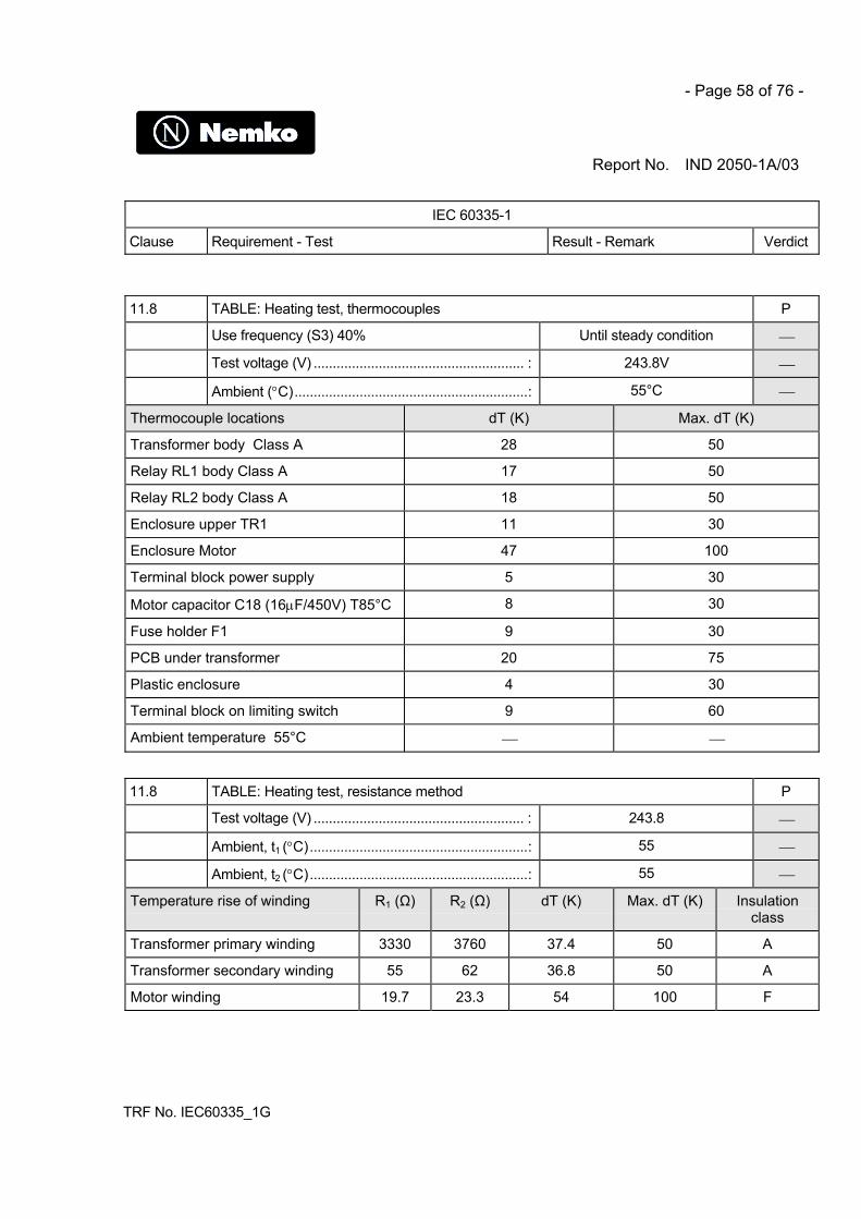
- Page 58 of 76 -
Report No. IND 2050-1A/03
IEC 60335-1
Clause Requirement - Test Result - Remark Verdict
TRF No. IEC60335_1G
11.8 TABLE: Heating test, thermocouples P
Use frequency (S3) 40% Until steady condition
Test voltage (V) ....................................................... : 243.8V
Ambient (°C).............................................................: 55°C
Thermocouple locations dT (K) Max. dT (K)
Transformer body Class A 28 50
Relay RL1 body Class A 17 50
Relay RL2 body Class A 18 50
Enclosure upper TR1 11 30
Enclosure Motor 47 100
Terminal block power supply 5 30
Motor capacitor C18 (16µF/450V) T85°C 8 30
Fuse holder F1 9 30
PCB under transformer 20 75
Plastic enclosure 4 30
Terminal block on limiting switch 9 60
Ambient temperature 55°C
11.8 TABLE: Heating test, resistance method P
Test voltage (V) ....................................................... : 243.8
Ambient, t1 (°C).........................................................: 55
Ambient, t2 (°C).........................................................: 55
Temperature rise of winding R1 (Ω) R2 (Ω) dT (K) Max. dT (K) Insulationclass
Transformer primary winding 3330 3760 37.4 50 A
Transformer secondary winding 55 62 36.8 50 A
Motor winding 19.7 23.3 54 100 F

- Page 59 of 76 -
Report No. IND 2050-1A/03
IEC 60335-1
Clause Requirement - Test Result - Remark Verdict
TRF No. IEC60335_1G
13.2 TABLE: Leakage current P
Heating appliances: 1.15 x rated input..................:
Motor-operated and combined appliances:1.06 x rated voltage ...............................................:
243.8V
Leakage current between I (mA) Max. allowed I (mA)
Between live parts and accessible metal parts < 0.21 3.5
Class II construction <0.1 0.25
13.3 TABLE: Electric strength P
Test voltage applied between: Voltage (V) Breakdown(Yes/No)
Between live parts and accessible metal parts 1750 No
Between live parts and accessible plastic parts 3000 No
Between primary windings of transformer and secondarywindings (reinforced insulation)
3750 No
14 TABLE: Transient overvoltages N
Clearance between: Cl (mm) RequiredCl (mm)
Rated impulsevoltage (V)
Impulse testvoltage (V)
Flashover(Yes/No)
16.2 TABLE: Leakage current P
Single phase appliances: 1.06 x rated voltage .....: 243.8V P
Three phase appliances 1.06 x rated voltagedivided by √3: .........................................................:
Not applicable
Leakage current between I (mA) Max. allowed I (mA)
Between live parts and accessible metal parts < 0.24 3.5
Class II construction <0.1 0.25

- Page 60 of 76 -
Report No. IND 2050-1A/03
IEC 60335-1
Clause Requirement - Test Result - Remark Verdict
TRF No. IEC60335_1G
16.3 TABLE: Electric strength P
Test voltage applied between: Voltage (V) Breakdown(Yes/No)
Between live parts and accessible metal parts 1750 No
Between live parts and accessible plastic parts 3000 No
Between primary windings of transformer and secondarywindings (reinforced insulation)
3750 No
17 TABLE: Overload protection, or short circuit P
Temperature rise of part/at: T (°C) Max. T (°C)
Sealed transformer Body (Thermocouple method) 107 150
Primary winding (Resistance method) 112 150
Secondary winding (Resistance method) 116 150
Ambient temperature 25°C
Short circuit applied on secondary winding Isc= 0.27A until steady condition
19.7 TABLE: Abnormal operation, locked rotor/moving parts P
Test voltage (V) ....................................................... : 230
Ambient, t1 (°C).........................................................: 55
Ambient, t2 (°C).........................................................: 55
Temperature of winding R1 (Ω) R2 (Ω) dT (K) T (°C) Max. T (°C)
Motor winding (class F) 19.7 25.7 88.3 146°C 180°C
Thermal protection operated on motor winding
19.9 TABLE: Abnormal operation, running overload P
Test voltage (V) ....................................................... : 230
Ambient, t1 (°C).........................................................: 25°C

- Page 61 of 76 -
Report No. IND 2050-1A/03
IEC 60335-1
Clause Requirement - Test Result - Remark Verdict
TRF No. IEC60335_1G
Ambient, t2 (°C).........................................................: 25°C
Temperature of winding R1 (Ω) R2 (Ω) dT (K) T (°C) Max. T (°C)
Motor winding (class F) 19.7 25.1 79.8 140 180°C
Before trip point of thermal protection rated 140°C
19.13 TABLE: Abnormal operation, temperature rises P
Thermocouple locations dT (K) Max. dT (K)
Test corner near motor enclosure 28 <150
Motor enclosure 75 <150
Plastic enclosure 15 30
Enclosure upper TR1 15 30
PCB under transformer 24 75
Terminal block power supply 8 55
Fuse holder F1 12 30
Motor capacitor C18 (16µF/450V) T85°C 15 30
Relay 21 30

- Page 62 of 76 -
Report No. IND 2050-1A/03
IEC 60335-1
Clause Requirement - Test Result - Remark Verdict
TRF No. IEC60335_1G
24.1 TABLE: Components P
Object / part No. Manufacturer/trademark
Type / model Technical data Standard Mark(s) ofconformity
Transformerprotected byexternal fuse
FAAC 7.50.138 Input 230VOutput 18V50Hz / 15VAClass FInsul. 4000V
EN 60742 :89+A1:92EN 61558-1EN61558-2-6
Tested inappliance
PWB circuitwith:
FAAC 200BT540 1.5mm FR4 T=130°C UL94-V0
EN 60335-1UL (E45546)
Tested inappliance
Relay RL1-RL2 IMO SRRN-2C-F 5A 250V T70°Ccoil 24Vdc
EN 60255 CSA,VDE,UR
AlternativeRelay RL1-RL2
FEME MZP A 001..5 5A 250V T125°C EN 60255 NEMKO,S,D;IMQ,VDE,
AlternativeRelay RL1-RL2
SCHRACKCOMPONENTS
Series RTPOWER PCBRELAY
5A 250V T125°C EN 60255 IMQ,VDE,UL
Mains supplyterminal blockmale- female
PHOENIX MSTB 2,5/STMSTBVA 2,5/G
250V/12AAWG24-12T105° 94V-0
CEI 23-20 S+,VDE,CSA,UL
AlternativeTerminal blockmale female
PTRMESSTECHNIK
AK(Z) 950STL(Z) 950
250V /12A 5,08mmT105° 94V-0
UL 1059CSA22.2 158VDE 0627
UL,VDE,CSA
AlternativeTerminal blockJ1,J2
SAURO AK(Z) 950STL(Z) 950
250V /12A 5,08mmT105° 94V-0
IEC 664-1UL 1059CSA22.2 158VDE 0627
UL,VDE,CSAIMQ

- Page 63 of 76 -
Report No. IND 2050-1A/03
IEC 60335-1
Clause Requirement - Test Result - Remark Verdict
TRF No. IEC60335_1G
24.1 TABLE: Components continue P
Object / partNo.
Manufacturer/trademark
Type / model Technical data Standard Mark(s) ofconformity
Mains fuse F1- FUSIT 5x20mm2 F1=T6.3A/250V EN 60127 IMQ
Fuse holderwith cover F1-
FUSIT 5x20mm2 250V/10A EN 60127 IMQ,S,VDE
Capacitors C1C2
ARCOTRONICS R46 MKP 0,47uF,275Vac, X240/100/56
IEC 384-14 NEMKO,IMQ,VDE,S,D
FusibleResistors R1-R2 (overloadprotection withoutrisk of fire)
BCCOMPONENTS
NFR25/25Hseries E24
1000Ω IEC 60115-1/2IEC60068-2
Limit switch BURGESS V4NCS2/3302 T85°C CSA 1113639CA 82858UL E90700
CSA,UL, FIMKO
Starting motorcapacitor
FACON 7G75160L67 16µF/400V50Hz
IEC-60252 VDE, SEV
Electric motor Single phaseinduction
230Vac 50Hz Tested inappliance
Motor windingthermalprotection
Thermik S05.120.5 230Vac 50HzT 140°C
Tested inappliance
28.1 TABLE: Threaded part torque test P
Threaded part identification Diameter of thread(mm)
Column number (I, II, or III)
Applied torque ( Nm )
Provision for earthingcontinuity fixed by screw andlock washer to the metalframe
∅3mm II 0.5

- Page 64 of 76 -
Report No. IND 2050-1A/03
IEC 60335-1
Clause Requirement - Test Result - Remark Verdict
TRF No. IEC60335_1G
29.1 TABLE: Clearances P
Overvoltage category....: Category II
Type of insulation:
Rated impulsevoltage (V):
Min. cl(mm)
Basic Functional Supplementary Reinforced Verdict / Remark
0,5
0,5
0,5
1,0
2500 2,0 B Pass
3,5
6,0
8,5
11,5
29.2 TABLE: Creepage distances, basic, supplementary and reinforced insulation P
Working voltage(V)
Creepage distance(mm)
Pollution degree
1 2 3 Type of insulation B
Material group Material group
I II IIIa/IIIb I II IIIa/IIIb B*) S*) R*) Verdict
≤50 0,2 0,6 0,9 1,2 1,5 1,7 1,9
≤50 0,2 0,6 0,9 1,2 1,5 1,7 1,9
≤50 0,4 1,2 1,8 2,4 3,0 3,4 3,8
>50 and ≤125 0,3 0,8 1,1 1,5 1,9 2,1 2,4
>50 and ≤125 0,3 0,8 1,1 1,5 1,9 2,1 2,4
>50 and ≤125 0,6 1,6 2,2 3,0 3,8 4,2 4,8
>125 and ≤250 0,6 1,3 1,8 2,5 3,2 3,6 4,0 P
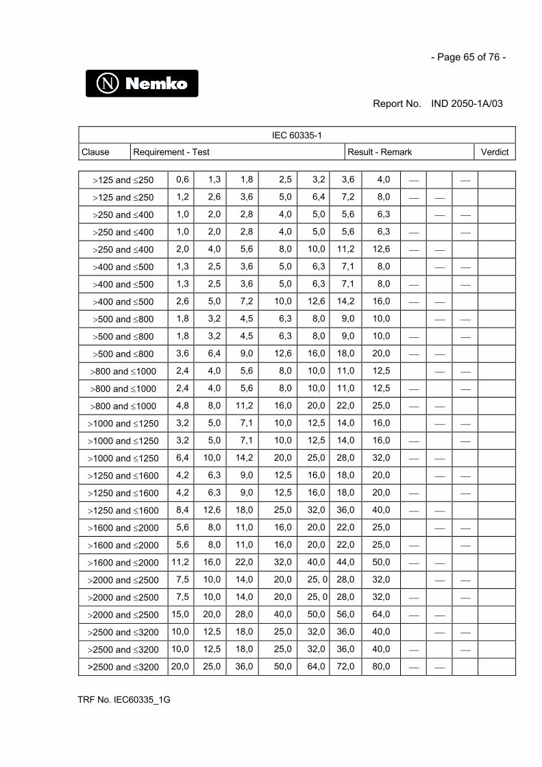
- Page 65 of 76 -
Report No. IND 2050-1A/03
IEC 60335-1
Clause Requirement - Test Result - Remark Verdict
TRF No. IEC60335_1G
>125 and ≤250 0,6 1,3 1,8 2,5 3,2 3,6 4,0
>125 and ≤250 1,2 2,6 3,6 5,0 6,4 7,2 8,0
>250 and ≤400 1,0 2,0 2,8 4,0 5,0 5,6 6,3
>250 and ≤400 1,0 2,0 2,8 4,0 5,0 5,6 6,3
>250 and ≤400 2,0 4,0 5,6 8,0 10,0 11,2 12,6
>400 and ≤500 1,3 2,5 3,6 5,0 6,3 7,1 8,0
>400 and ≤500 1,3 2,5 3,6 5,0 6,3 7,1 8,0
>400 and ≤500 2,6 5,0 7,2 10,0 12,6 14,2 16,0
>500 and ≤800 1,8 3,2 4,5 6,3 8,0 9,0 10,0
>500 and ≤800 1,8 3,2 4,5 6,3 8,0 9,0 10,0
>500 and ≤800 3,6 6,4 9,0 12,6 16,0 18,0 20,0
>800 and ≤1000 2,4 4,0 5,6 8,0 10,0 11,0 12,5
>800 and ≤1000 2,4 4,0 5,6 8,0 10,0 11,0 12,5
>800 and ≤1000 4,8 8,0 11,2 16,0 20,0 22,0 25,0
>1000 and ≤1250 3,2 5,0 7,1 10,0 12,5 14,0 16,0
>1000 and ≤1250 3,2 5,0 7,1 10,0 12,5 14,0 16,0
>1000 and ≤1250 6,4 10,0 14,2 20,0 25,0 28,0 32,0
>1250 and ≤1600 4,2 6,3 9,0 12,5 16,0 18,0 20,0
>1250 and ≤1600 4,2 6,3 9,0 12,5 16,0 18,0 20,0
>1250 and ≤1600 8,4 12,6 18,0 25,0 32,0 36,0 40,0
>1600 and ≤2000 5,6 8,0 11,0 16,0 20,0 22,0 25,0
>1600 and ≤2000 5,6 8,0 11,0 16,0 20,0 22,0 25,0
>1600 and ≤2000 11,2 16,0 22,0 32,0 40,0 44,0 50,0
>2000 and ≤2500 7,5 10,0 14,0 20,0 25, 0 28,0 32,0
>2000 and ≤2500 7,5 10,0 14,0 20,0 25, 0 28,0 32,0
>2000 and ≤2500 15,0 20,0 28,0 40,0 50,0 56,0 64,0
>2500 and ≤3200 10,0 12,5 18,0 25,0 32,0 36,0 40,0
>2500 and ≤3200 10,0 12,5 18,0 25,0 32,0 36,0 40,0
>2500 and ≤3200 20,0 25,0 36,0 50,0 64,0 72,0 80,0

- Page 66 of 76 -
Report No. IND 2050-1A/03
IEC 60335-1
Clause Requirement - Test Result - Remark Verdict
TRF No. IEC60335_1G
>3200 and ≤4000 12,5 16,0 22,0 32,0 40,0 45,0 50,0
>3200 and ≤4000 12,5 16,0 22,0 32,0 40,0 45,0 50,0
>3200 and ≤4000 25,0 32,0 44,0 64,0 80,0 90,0 100,0
>4000 and ≤5000 16,0 20,0 28,0 40,0 50,0 56,0 63,0
>4000 and ≤5000 16,0 20,0 28,0 40,0 50,0 56,0 63,0
>4000 and ≤5000 32,0 40,0 56,0 80,0 100,0 112,0 126,0
>5000 and ≤6300 20,0 25,0 36,0 50,0 63,0 71,0 80,0
>5000 and ≤6300 20,0 25,0 36,0 50,0 63,0 71,0 80,0
>5000 and ≤6300 40,0 50,0 72,0 100,0 126,0 142,0 160,0
>6300 and ≤8000 25,0 32,0 45,0 63,0 80,0 90,0 100,0
>6300 and ≤8000 25,0 32,0 45,0 63,0 80,0 90,0 100,0
>6300 and ≤8000 50,0 64,0 90,0 126,0 160,0 180,0 200,0
>8000 and ≤10000 32,0 40,0 56,0 80,0 100,0 110,0 125,0
>8000 and ≤10000 32,0 40,0 56,0 80,0 100,0 110,0 125,0
>8000 and ≤10000 64,0 80,0 112,0 160,0 200,0 220,0 250,0
>10000 and ≤12500 40,0 50,0 71,0 100,0 125,0 140,0 160,0
>10000 and ≤12500 40,0 50,0 71,0 100,0 125,0 140,0 160,0
>10000 and ≤12500 80,0 100,0 142,0 200,0 250,0 280,0 320,0
*), B=Basic, S=Supplementary and R=Reinforced
29.2 TABLE: Creepage distances, functional insulation N
Working voltage(V)
Creepage distance(mm)
Pollution degree
1 2 3
Material group Material group
I II IIIa/IIIb I II IIIa/IIIb Verdict / Remark
≤50 0,2 0,6 0,8 1,1 1,4 1,6 1,8
>50 and ≤125 0,3 0,7 1,0 1,4 1,8 2,0 2,2

- Page 67 of 76 -
Report No. IND 2050-1A/03
IEC 60335-1
Clause Requirement - Test Result - Remark Verdict
TRF No. IEC60335_1G
>125 and ≤250 0,4 1,0 1,4 2,0 2,5 2,8 3,2
>250 and ≤400 0,8 1,6 2,2 3,2 4,0 4,5 5,0
>400 and ≤500 1,0 2,0 2,8 4,0 5,0 5,6 6,3
>500 and ≤800 1,8 3,2 4,5 6,3 8,0 9,0 10,0
>800 and ≤1000 2,4 4,0 5,6 8,0 10,0 11,0 12,5
>1000 and ≤1250 3,2 5,0 7,1 10,0 12,5 14,0 16,0
>1250 and ≤1600 4,2 6,3 9,0 12,5 16,0 18,0 20,0
>1600 and ≤2000 5,6 8,0 11,0 16,0 20,0 22,0 25,0
>2000 and ≤2500 7,5 10,0 14,0 20,0 25,0 28,0 32,0
>2500 and ≤3200 10,0 12,5 18,0 25,0 32,0 36,0 40,0
>3200 and ≤4000 12,5 16,0 22,0 32,0 40,0 45,0 50,0
>4000 and ≤5000 16,0 20,0 28,0 40,0 50,0 56,0 63,0
>5000 and ≤6300 20,0 25,0 36,0 50,0 63,0 71,0 80,0
>6300 and ≤8000 25,0 32,0 45,0 63,0 80,0 90,0 100,0
>8000 and ≤10000 32,0 40,0 56,0 80,0 100,0 110,0 125,0
>10000 and ≤12500 40,0 50,0 71,0 100,0 125,0 140,0 160,0
30.1 TABLE: Ball pressure P
Part Test temperature (°C) Impression diameter(mm)
Allowed impressiondiameter (mm)
Plastic enclosure 75°C 1.3mm 2mm
Mains terminal Block 125°C 1.0mm 2mm

- Page 68 of 76 -
Report No. IND 2050-1A/03
TRF No. IEC60335_1G
Annex 1: EN 12453:2000 Industrial, commercial and garage doors and gates.
Safety in use of power operated doors –RequirementsClause 5.2.1
Clause Requirement – Test Result – Remark Ver-dict
Electric drive units for all kind of doors and gatesshall meet the requirements ofEN 60335-1: 1994 which applies with the followingexceptions and additions:
Considered
5.2.1 Clause 1 is applicable except the first indent ofNOTE 3;
Considered
Clause 4 is applicable except:
4.2 subclause replaced by the following Considered
When the test has to be carried out with a door,that door, specified as suitable for installation withthe drive which gives the most unfavourablecondition, is used and adjusted in accordance withthe instruction for installation for that test.
The tests are performed withouta door because the customerdeclare that the variation ofmotor charge current with theappliance loaded or unloaded isa little tenth of Ampere.
__
4.7 subclause modified as follows: Considered
If temperature has influence on the performance,the safety related test shall be performed at themost unfavourable temperature within thetemperature range specified by the manufacturer.
In instruction sheet –20°C+55°C
Tests performed at 55°C
P
4.10.1 subclause added Considered
Where it is indicates that a test may be carried outwithout a door, it may be tested using a plate orsimilar equipment of the most unfavourable size,and load within the manufacturer’s specifications tosimulate the door.
See clause 4.2 P
6 Clause 6 is applicable with the following addition:
6.2 Drives or parts of drives, except those of class III,which can be exposed to outdoor conditions shallbe at least IPX4. Protective equipment, wich can beexposed to outdoors conditions, except those ofclass III, shall be at least IP44 (see EN 60529)
Drive for indoor and outdooruse (IP54) test performed
P
7 Clause 7 i with the following amendaments: Considered
7.1 The rated output force or torque shall be marked; 50Nm on label P
7.12 Is not applicable

- Page 69 of 76 -
Report No. IND 2050-1A/03
TRF No. IEC60335_1G
7.13 Is not applicable
8 Clause 8 is applicable with the following addition:
8.2 Parts separated from live parts by basic insulationonly can be touched during adjustment if a tool isneeded to gain access to the adjustment means.
P
9 Clause 9 is not applicable Considered __
10 Clause 10 is applicable except as follows: Considered
10.1 subclause modified as follows: Considered
Instead of determining the mean value, the powerinput is determined as the maximum value, theeffect of inrush current being ignored.
Power rated 800WMeasured 490 WNegative deviation allowed
P
10.2 subclause modified as follows: Considered
Instead of determining the mean value, the currentvalue is determined as the maximum value, theeffect of inrush current being ignored.
Current rated 3.5AMeasured 2.1ANegative deviation allowed
P
11 Clause 11 is applicable except as follows: Considered
11.7 subclause replaced by: Considered
Drives which are designed for continuos operationare operated for consecutive operating cycles, untilsteady state condition are reached. Other drivesare operated for five cycles of opening and closingor the rated number of operating cycles, whicheveris the greater , by simulating the operation of themost unfavourable door in size and weightaccording to the manufacturers specification,without rest period.
Test performed asspecification on the instructionsheet, according tomanufacturer instructions.Use duty cycle 40%
And with a drive operated forfive cycles of opening andclosing without rest period.Operation: adjusted limitswitch to have the mostunfavourable condition:53 sec. period open operation53 sec. period close operation
Temperature rise not exceedingThermal protector not operate
P
18 Clause 18 is not applicable Considered
19 Clause 19 is applicable except as follows: Considered
19.13 Sublause applicable with the following addition: Considered
After each test, if the drive can still be operated, itshall comply with 5.1.1.5 of EN 12453
According to manufacturerrequest test not performed
__
20 Clause 20 is not applicable Considered
22 Clause 22 is applicable except as follows: Considered

- Page 70 of 76 -
Report No. IND 2050-1A/03
TRF No. IEC60335_1G
22.22 subclause modified as: Considered
Asbestos shall not be used in the construction ofthe drive.
Asbsetos not used P
24 Sublause applicable with the following addition: Considered
24.1.3 The number of cycles of operation for switcheswhich disconnect the appliance when the manualrelease is operated is 300.
Mains switches not present N
25 Clause 25 is applicable with the following addition: Considered
25.7 The supply cord of drives for outdoor use shall notbe lighter than ordinary polychloroprene sheathedflexible cord (code designation 245 IEC57according to IEC 60245-4).
Fixed wiring N
25.25 Interconnection cables shall be positioned to avoiddamages or protected against damages.
P
30 Clause 30 is applicable except subclause 30.2.2 Considered
31 Clause 31 is applicable with the following addition:
For parts intended to be installed externally,compliance is checked by the salt mist test of(IEC60068-2-52) severity 2, beign applicable.
P
Before the test coatings are scratched by means ofa hardned steel pin, the end of which has the formof a cone with an angle of 40°. Its tip is roundedwith a radius of 0.25 mm ± 0.2 mm. The pin isloaded so that the force extented along its axis is10 N ± 0.5 N. The scratches are made at least 5mm apart and at least 5 mm from the edges.After the test the appliance shall not havedeteriorated to such an extent that compliance withEN 60335-1, in particular with clauses 8 and 27, isimpaired. The coating shall not be broken and shallnot have loosened from the metal surface.
P

- Page 71 of 76 -
Report No. IND 2050-1A/03
TRF No. IEC60335_1G
Annex 2:Pictures
Fig.1 Global view
Fig.2 Global view
Fig.3 Global view

- Page 72 of 76 -
Report No. IND 2050-1A/03
TRF No. IEC60335_1G
Fig.4 IP5X dust test
Fig.5 IPX4 spray test
Fig.6 Heating test in climatic chamber
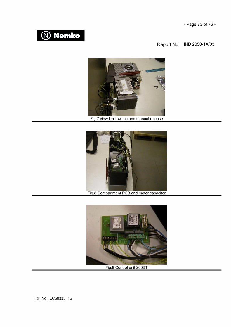
- Page 73 of 76 -
Report No. IND 2050-1A/03
TRF No. IEC60335_1G
Fig.7 view limit switch and manual release
Fig.8 Compartment PCB and motor capacitor
Fig.9 Control unit 200BT

- Page 74 of 76 -
Report No. IND 2050-1A/03
TRF No. IEC60335_1G
Fig.9 Control unit 200BT
Fig.10 Motor
Fig.11 Motor

- Page 75 of 76 -
Report No. IND 2050-1A/03
TRF No. IEC60335_1G
Fig.12 Mechanism driver
Fig.13 Mechanism driver

- Page 76 of 76 -
Report No. IND 2050-1A/03
TRF No. IEC60335_1G
Fig.14 shaft motor drive