iec 61850 library · • read all safety instructions of the ac500 plc. see system description...
TRANSCRIPT

— AC500 PLC
IEC 61850 Library
V3 Example Project Description


— AC500 PLC
IEC 61850 Library
V3 Example Project Description

—
NOTICE
This document contains information about one or more ABB products and may include a description
of or a reference to one or more standards that may be generally relevant to the ABB products. The
presence of any such description of a standard or reference to a standard is not a representation that
all of the ABB products referenced in this document support all of the features of the described or
referenced standard. In order to determine the specific features supported by a particular ABB prod-
uct, the reader should consult the product specifications for the particular ABB product.
ABB may have one or more patents or pending patent applications protecting the intellectual prop-
erty in the ABB products described in this document.
The information in this document is subject to change without notice and should not be construed as
a commitment by ABB. ABB assumes no responsibility for any errors that may appear in this docu-
ment.
Products described or referenced in this document are designed to be connected and to communi-
cate information and data through network interfaces, which should be connected to a secure net-
work. It is the sole responsibility of the system/product owner to provide and continuously ensure a
secure connection between the product and the system network and/or any other networks that may
be connected.
The system/product owners must establish and maintain appropriate measures, including, but not
limited to, the installation of firewalls, application of authentication measures, encryption of data,
installation of antivirus programs, and so on, to protect these products, the network, its system, and
interfaces against security breaches, unauthorized access, interference, intrusion, leakage, and/or
theft of data or information.
ABB performs functionality testing on the products and updates that we release. However, sys-
tem/product owners are ultimately responsible for ensuring that any product updates or other major
system updates (to include but not limited to code changes, configuration file changes, third-party
software updates or patches, hardware change out, and so on) are compatible with the security
measures implemented. The system/ product owners must verify that the system and associated
products function as expected in the environment in which they are deployed.
In no event shall ABB be liable for direct, indirect, special, incidental or consequential damages of any
nature or kind arising from the use of this document, nor shall ABB be liable for incidental or conse-
quential damages arising from use of any software or hardware described in this document.
This document and parts thereof must not be reproduced or copied without written permission from
ABB, and the contents thereof must not be imparted to a third party nor used for any unauthorized
purpose.
The software or hardware described in this document is furnished under a license and may be used,
copied, or disclosed only in accordance with the terms of such license. This product meets the re-
quirements specified in EMC Directive 2014/30/EU and in Low Voltage Directive 2014/35/EU.

A. For customers domiciled outside Germany /
Für Kunden mit Sitz außerhalb Deutschlands
„Warranty, Liability:
The user shall be solely responsible for the use of this products described within this file. ABB shall be
under no warranty whatsoever. ABB's liability in connection with application of the products or exam-
ples provided or the files included within this products, irrespective of the legal ground, shall be ex-
cluded. The exclusion of liability shall not apply in the case of intention or gross negligence. The pre-
sent declaration shall be governed by and construed in accordance with the laws of Switzerland under
exclusion of its conflict of laws rules and of the Vienna Convention on the International Sale of Goods
(CISG)."
„Gewährleistung und Haftung:
Der Nutzer ist allein für die Verwendung des in diesem Dokument beschriebenen Produkte und be-
schriebenen Anwendungsbeispiele verantwortlich.
ABB unterliegt keiner Gewährleistung. Die Haftung von ABB im Zusammenhang mit diesem Anwen-
dungsbeispiel oder den in dieser Datei enthaltenen Dateien - gleich aus welchem Rechtsgrund - ist
ausgeschlossen. Dieser Ausschluß gilt nicht im Falle von Vorsatz oder grober Fahrlässigkeit. Diese
Erklärung unterliegt Schweizer Recht unter Ausschluß der Verweisungsnormen und des UN-Kaufrechts
(CISG)."
B. Nur für Kunden mit Sitz in Deutschland
„Gewährleistung und Haftung:
Die in diesem dokument beschriebenen Anwendungsbeispiele oder enthaltenen Dateien beschreiben
eine mögliche Anwendung der AC500 bzw. zeigen eine mögliche Einsatzart. Sie stellen nur Beispiele
für Programmierungen dar, sind aber keine fertigen Lösungen. Eine Gewähr kann nicht übernommen
werden.
Der Nutzer ist für die ordnungsgemäße, insbesondere vollständige und fehlerfreie Programmierung
der Steuerungen selbst verantwortlich. Im Falle der teilweisen oder ganzen Übernahme der Program-
mierbeispiele können gegen ABB keine Ansprüche geltend gemacht werden.
Die Haftung von ABB, gleich aus welchem Rechtsgrund, im Zusammenhang mit den Anwendungsbei-
spielen oder den in dieser Datei enthaltenen Beschreibung wird ausgeschlossen. Der Haftungsaus-
schluß gilt jedoch nicht in Fällen des Vorsatzes, der groben Fahrlässigkeit, bei Ansprüchen nach dem
Produkthaftungsgesetz, im Falle der Verletzung des Lebens, des Körpers oder der Gesundheit oder
bei schuldhafter Verletzung einer wesentlichen Vertragspflicht. Im Falle der Verletzung einer wesentli-
chen Vertragspflicht ist die Haftung jedoch auf den vertragstypischen, vorhersehbaren Schaden be-
grenzt, soweit nicht zugleich ein anderer der in Satz 2 dieses Unterabsatzes erwähnten Fälle gegeben
ist. Eine Änderung der Beweislast zum Nachteil des Nutzers ist hiermit nicht verbunden.
Es gilt materielles deutsches Recht unter Ausschluß des UN-Kaufrechts."
—
TRADEMARKS
All rights to copyrights, registered trademarks, and trademarks reside with their respective owners.
Copyright © 2017 ABB.
All rights reserved.
Release: August 2017
Document number: 3ADR010262, 1, en_US

INTRODUCTION
3ADR010262, 1, en_US 1
—
TABLE OF CONTENTS
1. INTRODUCTION ........................................................................................................................ 2
1.1 Scope of the document .................................................................................................. 2
1.2 Overview of the Content ................................................................................................ 2
1.3 Safety Instructions and Preconditions ......................................................................... 3
2. OVERVIEW ............................................................................................................................... 4
2.1 Installation ..................................................................................................................... 4
2.2 Hardware and Software requirement .......................................................................... 4
2.3 Limitations ..................................................................................................................... 4
3. EXAMPLE A: AC500 AS MMS SERVER ..................................................................................... 6
3.1 Basic configuration ....................................................................................................... 6
3.2 Time sync ..................................................................................................................... 10
4. EXAMPLE B: TWO AC500 COMMUNICATING VIA GOOSE .................................................... 12
4.1 Set up GOOSE communication .................................................................................... 12
4.2 Close the Ping-Pong loop and run ............................................................................... 17
5. EXAMPLE C: AC500 CONTROLLING ABB IED REF615........................................................... 19
5.1 Configure Goose commands from AC500 to REF615 ............................................... 20
5.2 Configure Goose feedback from REF615 to AC500 ................................................... 23
5.3 Run the example .......................................................................................................... 26
6. EXPERT FEATURES ................................................................................................................ 28
6.1 Bulk data engineering ................................................................................................. 28
6.2 Add new logical node types ........................................................................................ 28

2 3ADR010262, 1, en_US
1. INTRODUCTION
1.1 Scope of the document
This document describes the example for IEC 61850 Server 4.0.4 which comes with Automation
Builder 2.2.0.
This package allows the AC500 to act as an IED with IEC 61850 Server, Edition 1, providing the follow-
ing functionality:
• The IEC 61850 Server connects substation automation systems with PLC applications
• AC500 V3 CPU acts as an IED with IEC 61850 Server, Edition 1, allowing communication as
MMS Server and GOOSE Publisher and Subscriber
• Automation Builder is used as IED configuration tool for modelling the IEC 61850 data struc-
tures and connecting them to the PLC applications
• Support of SCL – Substation Configuration Language to transfer detailed configuration infor-
mation between different IEDs
This document describes the examples which are part of Automation Builder. The engineering pro-
cess with Automation Builder and 3rd party IED configuration tools is explained in order to setup the
communication with MMS and GOOSE.
1.2 Overview of the Content
Chapter 2 describes the required hardware and software including the necessary connections for set-
ting up the examples.
Chapter 3 contains the first example A where AC500 is configured as a simple MMS server which can
be accessed by any IEC 61850 MMS client, for example IEC Scout from Omicron.
In chapter 4 (Example B) two AC500 are configured as GOOSE Publisher and GOOSE Subscriber in
order to exchange data in both directions.
Chapter 5 describes Example C, where AC500 is controlling an IED from ABB, REF615, via GOOSE. A
Switch command is sent from AC500 to REF615. The resulting status of the Circuit breaker is re-
ported back from REF615 to AC500.
AC500

INTRODUCTION
3ADR010262, 1, en_US 3
1.3 Safety Instructions and Preconditions
The user has to read the following instructions and documents before using the libraries:
• All pertinent state, regional, and local safety regulations must be observed when installing and
using this product. When functions or devices are used for applications with technical safety
requirements, the relevant instructions must be followed.
• Read the complete safety instructions of the user's manuals for the devices you are using, be-
fore installation and commissioning.
• Read all safety instructions of the AC500 PLC. See System description AC500 in the online help
in Automation Builder
• Read the user Information of the devices and functions you are using, see online help in Automa-
tion Builder.
The IEC61850 Library package has been released for the software and firmware versions listed in the
Readme file of the package only.
In no event will ABB or its representatives be liable for loss of data, profits, revenue or consequential,
incidental or other damage that may result from the use of other versions of product, software or
firmware versions. The error-free operation of the High Availability Modbus TCP Library with other
devices, software or firmware versions should be possible but cannot be guaranteed and may need
adaptations e.g. of example programs.
The user must follow all applicable safety instructions and the guidelines mentioned in the user doc-
uments of the ABB products.
Read the complete safety instructions for the AC500 before installation and commissioning.
CAUTION!
Generally, the user in all applications is fully and alone responsible for checking all functions
carefully, especially for safe and reliable operation.
Note: The Function Blocks contained in the library can only be executed in RUN mode of the PLC,
but not in simulation mode.

4 3ADR010262, 1, en_US
2. OVERVIEW
The IEC 61850 Server is part of Automation Builder 2.1.1 and higher.
2.1 Installation
The IEC61850 Server package can be installed as an option.
General configuration of IEC61850 is described in the online help in the Add-ons area:
This document provides additional AC500 specific details and examples.
2.2 Hardware and Software requirement
The following table gives an overview of required hardware and software for the different examples.
In the columns A, B and C the required number of items for examples A, B and C is listed,
“man” stands for mandatory, “opt” for optionally.
Hardware Details A B C
AC500 V3 CPU PM56xx, FW 3.2.0 or higher, with IEC61850
runtime license 1 2 1
Ethernet Switch 1 1
IED for bay control
REF615 REF from ABB
or Demo Case (DSF615BJ2G) including REF615
plus simulation of a switchgear bay
1
Software on PC Details
Automation Builder V2.2.0 or higher man man man
IEC 61850 MMS client Omicron, IED Scout 4.2.0 or other client man
Ethernet sniffer Wireshark V2.4.2 or higher opt
IED engineering tool
PCM600 Version 2.8 including:
man
2.3 Limitations
• Edition 1 only
• Only MMS server, no MMS client. Workaround is to use GOOSE like in example C.

Overview
3ADR010262, 1, en_US 5
• The functionality behind the Logical Nodes need to be implemented by 61131 code
• Maximum of 5 Client connections per Server
• Maximum of 50 entries per Dataset
• Maximum of 20 DataSets and one Report per DataSet (PUA-167)
• Operation
o Speed: Max 3000 Byte per cycle. Example: With an IEC61850-cycle time of 2ms it takes at
least 10 ms to send 5 reports à 3000 Bytes
• Engineering
o Not possible to have 2 or more IEC61850 server in one AB project. Workaround: Create 2
or more projects (PUA-172)
o Only one Logical Node per IEC61850 Server
o When data objects are inserted the first one has no suffix, e.g. "Ind" instead of "Ind0"
(PUA-171)

6 3ADR010262, 1, en_US
3. EXAMPLE A: AC500 AS MMS SERVER
3.1 Basic configuration
Goal of this example is to configure the AC500 as IEC 61850 MMS Server, providing the mandatory
Logical nodes and some optional ones in order to publish data from IEC61131 application which can
be read by any IEC 61850 MMS client.
Physical connections: Ethernet connection between AC500 (V3) and the PC with Automation Builder
and MMS test client, e.g. IED Scout from Omicron.
The engineering steps are according to the Quickstart in the online help:
This chapter adds some details and screenshots for this specific example
1. Create a new project and insert the IEC 61850 Server
Create a new project with AC500 V3 PM5650
Connect to PLC and check if CPU firmware is 3.2.0 or higher.
Add IEC 61850 Server node below ETH1
Enter Server name = AC500_1
Enter IP address of the PLC = 192.168.84.200

EXAMPLE A: AC500 AS MMS SERVER
3ADR010262, 1, en_US 7
2. Add the Logical Device to the server
3. Add another LNC instance to the Logical Device
4. Expand the “XCBR” LNC instance with the optional “MaxOpCap” CDC instance
5. Link an attribute (DA) of the IEC 61850 Server with a CODESYS variable
8 3ADR010262, 1, en_US
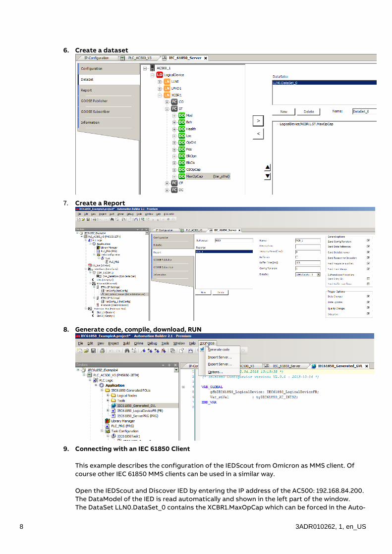
6. Create a dataset
7. Create a Report
8. Generate code, compile, download, RUN
9. Connecting with an IEC 61850 Client
This example describes the configuration of the IEDScout from Omicron as MMS client. Of
course other IEC 61850 MMS clients can be used in a similar way.
Open the IEDScout and Discover IED by entering the IP address of the AC500: 192.168.84.200.
The DataModel of the IED is read automatically and shown in the left part of the window.
The DataSet LLN0.DataSet_0 contains the XCBR1.MaxOpCap which can be forced in the Auto-

EXAMPLE A: AC500 AS MMS SERVER
3ADR010262, 1, en_US 9
mation Builder, for example to value 55. The same value is shown in the IEC Scout after press-
ing the button “Read” or “Read all”.
For an automatic update of the values the report can be enabled. Afterwards the AC500 ac-
tively sends a report when the value has changed, e.g. from 55 to 66:

10 3ADR010262, 1, en_US
3.2 Time sync
If an SNTP Server (e.g. Meinberg clock) is available in the network the AC500 can be config-
ured as SNTP client in order to receive and provide the correct time information in the MMS
and GOOSE reports.
Therefore an SNTP client node must be added and configured (SNTP Server is 192.168.84.250
in this example)
All parameter of SNPT client are described in the online help search for SNTP Client Config-
uration.
With the program “prgSNTP” the SNTP Server is scanned every 30 seconds and the resulting
quality bit is written to a pointer to the internal variable xClockNotSynchronized of
IEC61850_SyncClockOnRTC
• In step 0 the pointer is defined
• In step 2 the status of SNTP is checked and updated
• In step 1 a timer waits for 30 seconds until it goes back to step 2
If the SNTP time is working correctly the “ClockNotSynchronized” is False

EXAMPLE A: AC500 AS MMS SERVER
3ADR010262, 1, en_US 11
If the SNTP Server fails or connection is broken the “ClockNotSynchronized” is True:

12 3ADR010262, 1, en_US
4. EXAMPLE B: TWO AC500 COMMUNICATING VIA GOOSE
Goal of this example is setup a GOOSE communication between 2 AC500 PLCs.
AC500_B1 sends a “Ping” signal as GOOSE publisher. AC500_B2 receives this signal as GOOSE sub-
scriber. The answer “Pong” is sent from AC500_B2 to AC500_B1 in the same way.
Physical connections: Switch between AC500_B1 and AC500B2 and the PC with Automation Builder
and optionally Wireshark for monitoring the Ethernet traffic.
The following sub-chapter show all single engineering steps.
The alternative is to use the existing example projects. In this case the IP addresses and MAC ad-
dresses have to be adapted according to the hardware setup.
4.1 Set up GOOSE communication
The engineering is done in two Automation Builder projects, one for each AC500. The exchange of
engineering information is done with .icd files according to SCL = Substation Configuration Lan-
guage:
The configuration is done in 4 steps:
1. GOOSE publisher of AC500_B1, export of AC500_B1.icd
2. GOOSE subscriber of AC500_B2 by importing AC500_B1.icd
3. GOOSE publisher of AC500_B2, export of AC500_B2.icd
4. GOOSE subscriber of AC500_B1 by importing AC500_B2.icd
The details are explained in the following:
1. GOOSE publisher of AC500_B1
EXAMPLE B: TWO AC500 COMMUNICATING VIA GOOSE
3ADR010262, 1, en_US 13
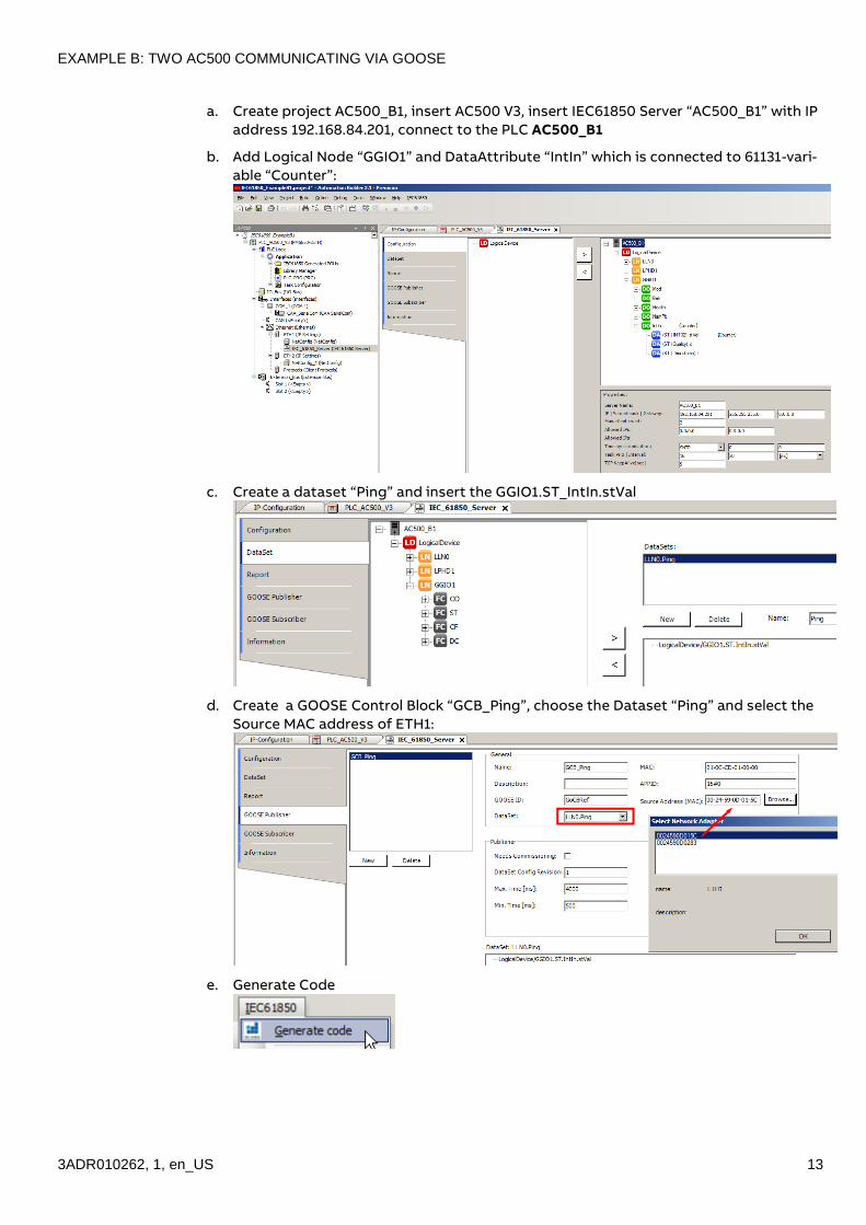
a. Create project AC500_B1, insert AC500 V3, insert IEC61850 Server “AC500_B1” with IP
address 192.168.84.201, connect to the PLC AC500_B1
b. Add Logical Node “GGIO1” and DataAttribute “IntIn” which is connected to 61131-vari-
able “Counter”:
c. Create a dataset “Ping” and insert the GGIO1.ST_IntIn.stVal
d. Create a GOOSE Control Block “GCB_Ping”, choose the Dataset “Ping” and select the
Source MAC address of ETH1:
e. Generate Code

14 3ADR010262, 1, en_US
f. Export configuration as AC500_B1.icd
2. GOOSE subscriber of AC500_B2
a. Create project AC500_B2, insert IEC61850 Server “AC500_B2” with IP address
192.168.84.202, connect to PLC AC500_B2
b. Configure GOOSE Subscriber by pushing the button “Import” and selecting the
AC500_B1.icd. In the “Import GOOSE control block” window the GCG_Ping can be cho-
sen by clicking “OK”

EXAMPLE B: TWO AC500 COMMUNICATING VIA GOOSE
3ADR010262, 1, en_US 15
c. The signal is automatically added to the list. By choosing the option “Use default
name”, the 61131 variable “GCB_Ping_Entry0” is generated automatically.
d. Furthermore the Source MAC address has to be selected.
Important: This must be the ETH1 MAC address of AC500_B2!
3. GOOSE publisher of AC500_B2
This is similar to step 1, merely “Ping” is substituted by “Pong”:
a. Project “IEC61850_ExampleB2” is already existing from previous step 2.
b. Add Logical Node “GGIO1” and DataAttribute “IntIn” which is connected to 61131-vari-
able “Counter”:
c. Create a dataset “Pong” and insert the GGIO1.ST_IntIn.stVal
d. Create a GOOSE Control Block “GCB_Pong”, choose the Dataset “Pong” and select the
Source MAC address of ETH1.

16 3ADR010262, 1, en_US
Important: Choose a different APPID, e.g. 16#1 (AC500_B1 had 16#0)
e. Generate Code
f. Export configuration as AC500_B2.icd
4. GOOSE subscriber of AC500_B2
This is similar to step 2
a. Open project IEC61850_ExampleB1
b. Configure GOOSE Subscriber by pushing the button “Import” and selecting the
AC500_B2.icd. In the “Import GOOSE control block” window the GCG_Pong can be
chosen by clicking “OK”
c. The signal is automatically added to the list. By choosing the option “Use default
name”, the 61131 variable “GCB_Pong_Entry0” is generated automatically.
d. Furthermore the Source MAC address has to be selected.
Important: This must be the ETH1 MAC address of AC500_B1!

EXAMPLE B: TWO AC500 COMMUNICATING VIA GOOSE
3ADR010262, 1, en_US 17
Now the Ping-Pong communication between the two PLCs is configured.
4.2 Close the Ping-Pong loop and run
To close the Ping-Pong loop a 1-line application needs to be created which receives the Ping and
writes the Pong (through the variable counter) and vice-versa:
Now both programs can be compiled, downloaded and set to “Run”
The Ping-Pong can be monitored by opening the two projects with 2 Automation Builder:
By using a sniffer program like Wireshark the GOOSE messages on the Ethernet can be observed af-
ter the firewall is configured accordingly:

18 3ADR010262, 1, en_US
EXAMPLE C: AC500 CONTROLLING ABB IED REF615
3ADR010262, 1, en_US 19
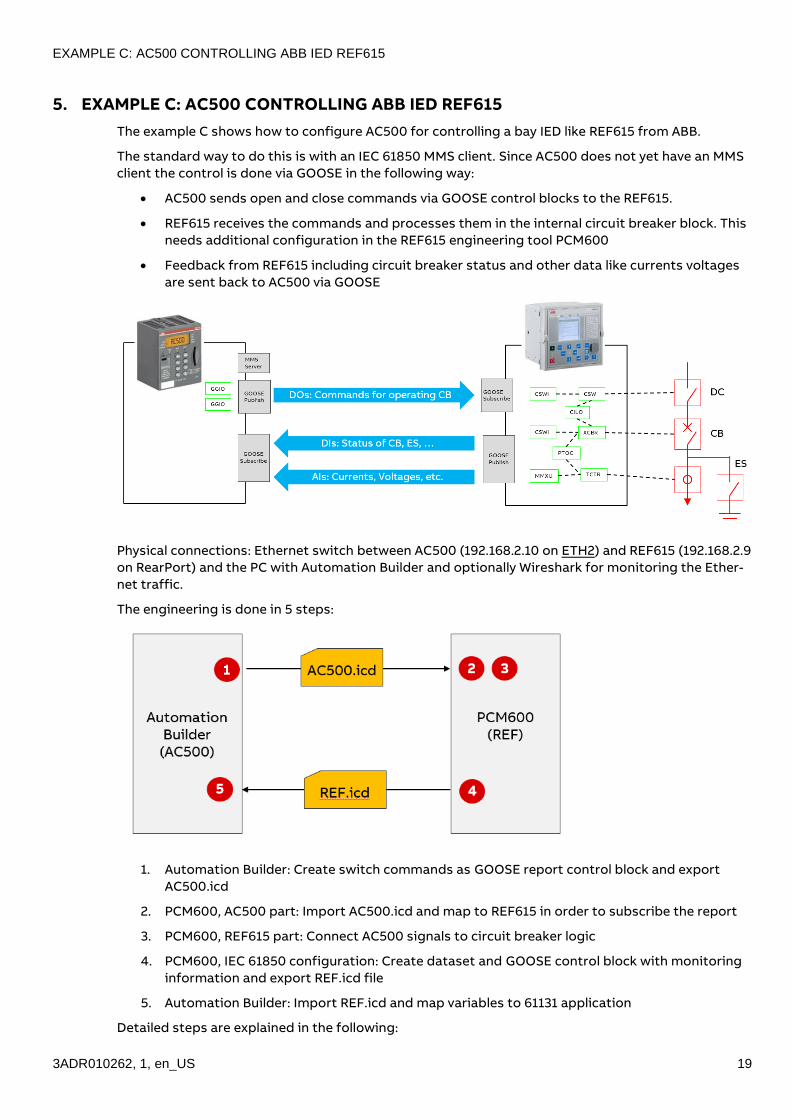
5. EXAMPLE C: AC500 CONTROLLING ABB IED REF615
The example C shows how to configure AC500 for controlling a bay IED like REF615 from ABB.
The standard way to do this is with an IEC 61850 MMS client. Since AC500 does not yet have an MMS
client the control is done via GOOSE in the following way:
• AC500 sends open and close commands via GOOSE control blocks to the REF615.
• REF615 receives the commands and processes them in the internal circuit breaker block. This
needs additional configuration in the REF615 engineering tool PCM600
• Feedback from REF615 including circuit breaker status and other data like currents voltages
are sent back to AC500 via GOOSE
Physical connections: Ethernet switch between AC500 (192.168.2.10 on ETH2) and REF615 (192.168.2.9
on RearPort) and the PC with Automation Builder and optionally Wireshark for monitoring the Ether-
net traffic.
The engineering is done in 5 steps:
1. Automation Builder: Create switch commands as GOOSE report control block and export
AC500.icd
2. PCM600, AC500 part: Import AC500.icd and map to REF615 in order to subscribe the report
3. PCM600, REF615 part: Connect AC500 signals to circuit breaker logic
4. PCM600, IEC 61850 configuration: Create dataset and GOOSE control block with monitoring
information and export REF.icd file
5. Automation Builder: Import REF.icd and map variables to 61131 application
Detailed steps are explained in the following:

20 3ADR010262, 1, en_US
5.1 Configure Goose commands from AC500 to REF615
Goal is to send two switch commands from AC500 variables to the REF615 circuit breaker block:
• IED2_CB_Close to input AU_CLOSE of CBXCBR1
• IED2_CB_Open to input AU_OPEN of CBXCBR1
The following picture shows a simplified signal chain over GOOSE:
On AC500 side the signals are mapped to IEC 61850 data model (Logical Node GGIO, Data object
Ind), packed into datasets and sent as Goose control blocks.
On REF615 side the GOOSE signals are subscribed, mapped to the GOOSE_RCV_BIN blocks and con-
nected to the Auxilliary inputs of the Circuit breaker CBXCBR1.
1. Automation Builder: Create switch commands as GOOSE report control block
a. Create project AC500_C, insert AC500 V3, insert IEC61850 Server “AC500” with IP ad-
dress 192.168.2.10, connect to the PLC AC500
b. Add two logical nodes of type GGIO, one for Close: CLGGIO1, one for Open: OPGGIO2
EXAMPLE C: AC500 CONTROLLING ABB IED REF615
3ADR010262, 1, en_US 21
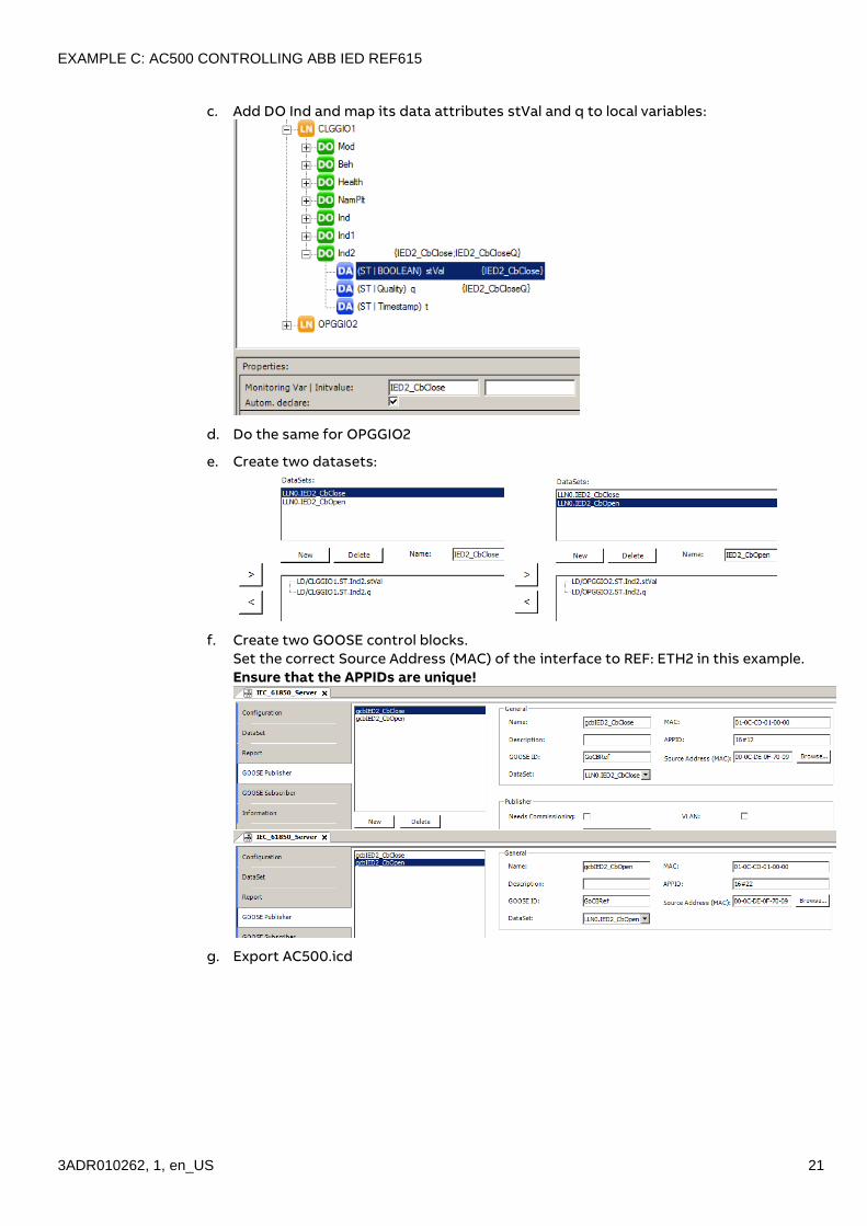
c. Add DO Ind and map its data attributes stVal and q to local variables:
d. Do the same for OPGGIO2
e. Create two datasets:
f. Create two GOOSE control blocks.
Set the correct Source Address (MAC) of the interface to REF: ETH2 in this example.
Ensure that the APPIDs are unique!
g. Export AC500.icd
22 3ADR010262, 1, en_US
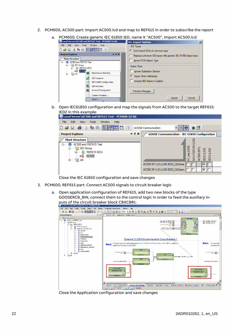
2. PCM600, AC500 part: Import AC500.icd and map to REF615 in order to subscribe the report
a. PCM600: Create generic IEC 61850 IED, name it “AC500”, Import AC500.icd
b. Open IEC61850 configuration and map the signals from AC500 to the target REF615:
IED2 in this example:
Close the IEC 61850 configuration and save changes
3. PCM600, REF615 part: Connect AC500 signals to circuit breaker logic
a. Open application configuration of REF615, add two new blocks of the type
GOOSERCB_BIN, connect them to the control logic in order to feed the auxiliary in-
puts of the circuit breaker block CBXCBR1:
Close the Application configuration and save changes

EXAMPLE C: AC500 CONTROLLING ABB IED REF615
3ADR010262, 1, en_US 23
b. Open the signal matrix tool of REF615 and map the GOOSE signals from AC500 to the
new GOOSERCV_BIN blocks.
Close the Signal Matrix tool and save changes.
Now the AC500 is ready to send and the REF615 is ready to receive the switch commands over
GOOSE.
5.2 Configure Goose feedback from REF615 to AC500
4. PCM600, IEC 61850 configuration: Create dataset and GOOSE control block with monitoring
information and export REF.icd file
a. Create new Datasets and fill with data to send from REF to AC500, “StatusAna” for
analog values like currents, voltages of all 3 phases:
… and “StatusBin” for binary values, like switch position of circuit breaker, discon-
nector, earthing switch and local/remote status:

24 3ADR010262, 1, en_US
b. Create two new GOOSE controls for the new datasets
Ensure that the APPIDs are unique!
Close the IEC 61850 configuration and save changes
c. Export REF615.icd with default settings:
d. Write changes to IED (context menu – Write to IED…)

EXAMPLE C: AC500 CONTROLLING ABB IED REF615
3ADR010262, 1, en_US 25
5. Automation Builder: Import REF615.icd and map variables to 61131 application
a. Open …ExampleC.project and choose GOOSE Subscriber. Import REF615.icd file and
import both datasets from REF615.
b. Set the correct Source Address (MAC) of the interface to REF
c. Assign suitable Varnames:
Now the REF615 is ready to send and the AC500 is ready to receive the feedback signals over GOOSE.

26 3ADR010262, 1, en_US
5.3 Run the example
Compile download and set the AC500 to run.
Now the switchgear bay can be controlled with AC500:
In the global variables the currents and voltages of all 3 phases are shown. Furthermore the positions
of Disconnector (DC), Circuit Breaker (CB) and Earthing Switch (ES) can be monitored: 2 is open, 1 is
closed, 0 is intermediate state.
Switch commands can be issued by writing TRUE to IED2_CbClose or IED2_CbOpen.
All these variables are connected to a simple visualization which shows the single line of the switch-
gear bay including buttons for Open and Close the circuit breaker:

EXAMPLE C: AC500 CONTROLLING ABB IED REF615
3ADR010262, 1, en_US 27
The GOOSE traffic between the two IEDs can be monitored with Wireshark:

28 3ADR010262, 1, en_US
6. EXPERT FEATURES
6.1 Bulk data engineering
• Create basic IEC 61850 server configuration
• Menu - IEC61850 – Export Server – Save as type XML
• Enhance XML file by copying logical nodes, reports etc.
• Menu – IEC61850 – Import Server, type XML Configuration is updated
6.2 Add new logical node types
Logical nodes are stored in the device description file:
C:\ProgramData\AutomationBuilder\AB_Devices_2.1\512\0000 0001\4.0.3.0\IEC61850De-
viceDesc.xml
This file can be edited in order to enable prepared Logical nodes or to create new ones.
In this example the <Enable> tag of CSWI is set from 0 to 1.
After restart of AB the CSWI can be chosen:
Limitation of Logical nodes which are not enabled by default:
• Their compliance to IEC 61850-7-4 (Ed1) is not fully tested

EXPERT features
3ADR010262, 1, en_US 29
• Following Common Data Classes are not fully implemented:
They are needed by some (not enabled) Logical Nodes, for example MHAI.
Enabling such a Logical Node leads to compilation errors.

30 3ADR010262, 1, en_US
REVISION HISTORY
Rev. Page Change Description Date / Initial
-r1 all First version 2018-04-30
IAMF/AC500/Eg
-r2 Chapter 6.3
-r3 Updated for AB2.2.0 / FW 3.2.0 / IEC61850 Server 4.0.4
Chapter 4.2 deleted (promiscous mode by firmware)
Chapter 2.3 (Limitations) updated
2018-10-12
IAMF/AC500/Eg


__
__
ABB Automation Products GmbH
Wallstadter Str. 59
68526 Ladenburg, Germany
Phone: +49 62 21 701 1444
Fax : +49 62 21 701 1382
E-Mail: [email protected]
www.abb.com/plc
We reserve the right to make technical
changes or modify the contents of
this document without prior notice.
With regard to purchase orders, the
agreed particulars shall prevail. ABB
AG does not accept any responsibility
whatsoever for potential errors or
possible lack of information in this
document.
We reserve all rights in this document
and in the subject matter and illustra-
tions contained therein. Any reproduc-
tion, disclosure to third parties or utili-
zation of its contents – in whole or in
parts – is forbidden without prior writ-
ten consent of ABB AG.
Copyright© 2017 ABB. All rights re-
served
Do
cu
me
nt
Nu
mb
er
3A
DR
010
26
2, 1
, en
_US