iec connectors mains filters - bulgin connectors 292 iec connectors mains filters designed to reduce...
TRANSCRIPT

300 IEC Connectors
IEC ConnectorsMains Filters
Designed to reduce conducted mains borne EMI, this extensive rangeprovides many solutions to EMI problems. To meet individual designrequirements the filters are available with two attenuation options –standard and medical. Current ratings are from 1 to 10 amps with single or twin fused types also available.
The choice of mounting options will suit most applications with flange, snap to panel or base/bulkhead.
Flange and Snap FitPS00 SeriesPS01 Series Base Mounting and BulkheadPS02 SeriesPS03 Series
Fused InletsPS20 SeriesPS21 SeriesPS25 SeriesPS26 Series
294-295294-295
296-297296-297
298-299298-299300-301300-301
IEC Connectors 301
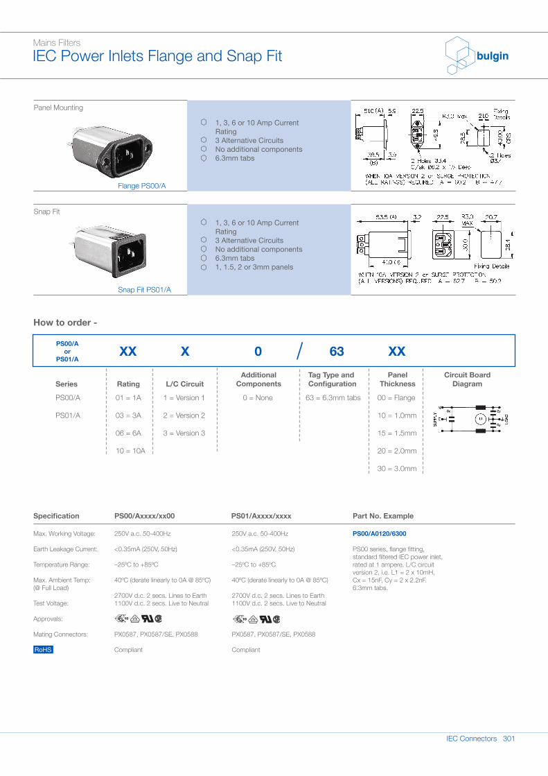
63 = 6.3mm tabs
Mains FiltersIEC Power Inlets Flange and Snap Fit
Panel Mounting
Snap Fit
Flange PS00/A
Snap Fit PS01/A
1, 3, 6 or 10 Amp CurrentRating3 Alternative CircuitsNo additional components6.3mm tabs
1, 3, 6 or 10 Amp CurrentRating3 Alternative CircuitsNo additional components6.3mm tabs1, 1.5, 2 or 3mm panels
PS00/A
PS01/A
Series Rating L/C CircuitAdditional
ComponentsTag Type andConfiguration
Panel Thickness
Circuit BoardDiagram
01 = 1A
03 = 3A
06 = 6A
10 = 10A
1 = Version 1
2 = Version 2
3 = Version 3
0 = None 00 = Flange
10 = 1.0mm
15 = 1.5mm
20 = 2.0mm
30 = 3.0mm
Specification
Max. Working Voltage:
Earth Leakage Current:
Temperature Range:
Max. Ambient Temp:(@ Full Load)
Test Voltage:
Approvals:
Mating Connectors:
RoHS
PS00/Axxxx/xx00
250V a.c. 50-400Hz
<0.35mA (250V, 50Hz)
–25ºC to +85ºC
40ºC (derate linearly to 0A @ 85ºC)
2700V d.c. 2 secs. Lines to Earth1100V d.c. 2 secs. Live to Neutral
PX0587, PX0587/SE, PX0588
Compliant
250V a.c. 50-400Hz
<0.35mA (250V, 50Hz)
–25ºC to +85ºC
40ºC (derate linearly to 0A @ 85ºC)
2700V d.c. 2 secs. Lines to Earth1100V d.c. 2 secs. Live to Neutral
PX0587, PX0587/SE, PX0588
Compliant
PS01/Axxxx/xxxx Part No. Example
PS00/A0120/6300
PS00 series, flange fitting,standard filtered IEC power inlet,rated at 1 ampere. L/C circuitversion 2, i.e. L1 = 2 x 10mH,Cx = 15nF, Cy = 2 x 2.2nF.6.3mm tabs.
XXX 0 63 XX
How to order -
PS00/A or
PS01/A
302 IEC Connectors
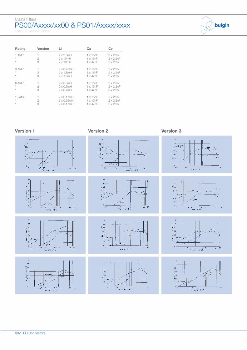
Rating & Version Tables
Mains FiltersPS00/Axxxx/xx00 & PS01/Axxxx/xxxx
Rating
1 AMP““
3 AMP““
6 AMP““
10 AMP““
Version
123
123
123
123
L1
2 x 2.8mH2 x 10mH2 x 10mH
2 x 0.75mH2 x 1.8mH2 x 1.8mH
2 x 0.3mH2 x 0.7mH2 x 0.7mH
2 x 0.17mH2 x 0.35mH2 x 0.17mH
Cx
1 x 15nF1 x 15nF1 x 47nF
1 x 15nF1 x 15nF1 x 47nF
1 x 15nF1 x 15nF1 x 47nF
1 x 15nF1 x 15nF1 x 47nF
Cy
2 x 2.2nF2 x 2.2nF2 x 2.2nF
2 x 2.2nF2 x 2.2nF2 x 2.2nF
2 x 2.2nF2 x 2.2nF2 x 2.2nF
2 x 2.2nF2 x 2.2nF2 x 2.2nF
Version 1 Version 2 Version 3
IEC Connectors 303
Mains FiltersBase Mounting and Bulkhead
Base Mounting
Bulkhead Mounting
Base Mounting PS02/A
Bulkhead Mounting PS03/A
1, 3, 6 or 10 Amp CurrentRating3 Alternative CircuitsNo additional components6.3mm tabs
1, 3, 6 or 10 Amp CurrentRating3 Alternative CircuitsNo additional components6.3mm tabs
Specification
Max. Working Voltage:
Earth Leakage Current:
Temperature Range:
Max. Ambient Temp:(@ Full Load)
Test Voltage:
Approvals:
RoHS
PS02/Axxxx/xx
250V a.c. 50-400Hz
<0.35mA (250V, 50Hz)
–25ºC to +85ºC
40ºC (derate linearly to 0A @ 85ºC)
2700V d.c. 2 secs. Lines to Earth1100V d.c. 2 secs. Live to Neutral
Compliant
250V a.c. 50-400Hz
<0.35mA (250V, 50Hz)
–25ºC to +85ºC
40ºC (derate linearly to 0A @ 85ºC)
2700V d.c. 2 secs. Lines to Earth1100V d.c. 2 secs. Live to Neutral
Compliant
PS03/Axxxx/xx Part No. Example
PS02/A0120/63
PS02 series, standard basemounting filter, rated at 3amperes. L/C circuit version 1,i.e. L1 = 2 x 0.75mH, Cx =15nF, Cy = 2 x 2.2nF with 2.8mm tabs.
How to order -
PS02/A
PS03/A
Series Rating L/C CircuitAdditional
ComponentsTag Type andConfiguration
Circuit BoardDiagram
01 = 1A
03 = 3A
06 = 6A
10 = 10A
1 = Version 1
2 = Version 2
3 = Version 3
0 = None 63 = 6.3mm tabs
XXX 0 63PS02/A
or PS03/A

304 IEC Connectors
Rating & Version Table
Mains FiltersPS02/Axxxx/xx & PS03/Axxxx/xx
Version 1 Version 2 Version 3
Rating
1 AMP““
3 AMP““
6 AMP““
10 AMP““
Version
123
123
123
123
L1
2 x 2.8mH2 x 10mH2 x 10mH
2 x 0.75mH2 x 1.8mH2 x 1.8mH
2 x 0.3mH2 x 0.7mH2 x 0.7mH
2 x 0.17mH2 x 0.35mH2 x 0.17mH
Cx
1 x 15nF1 x 15nF1 x 47nF
1 x 15nF1 x 15nF1 x 47nF
1 x 15nF1 x 15nF1 x 47nF
1 x 15nF1 x 15nF1 x 47nF
Cy
2 x 2.2nF2 x 2.2nF2 x 2.2nF
2 x 2.2nF2 x 2.2nF2 x 2.2nF
2 x 2.2nF2 x 2.2nF2 x 2.2nF
2 x 2.2nF2 x 2.2nF2 x 2.2nF
IEC Connectors 305
2 = Version 2
3 = Version 3
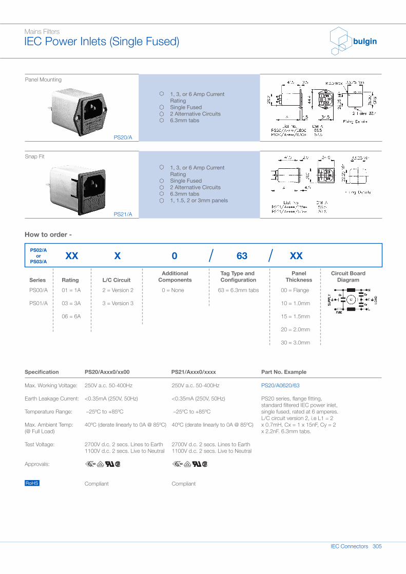
Mains FiltersIEC Power Inlets (Single Fused)
Panel Mounting
Snap Fit
PS20/A
PS21/A
1, 3, or 6 Amp CurrentRatingSingle Fused2 Alternative Circuits6.3mm tabs
1, 3, or 6 Amp CurrentRatingSingle Fused2 Alternative Circuits6.3mm tabs1, 1.5, 2 or 3mm panels
Specification
Max. Working Voltage:
Earth Leakage Current:
Temperature Range:
Max. Ambient Temp:(@ Full Load)
Test Voltage:
Approvals:
RoHS
PS20/Axxx0/xx00
250V a.c. 50-400Hz
<0.35mA (250V, 50Hz)
–25ºC to +85ºC
40ºC (derate linearly to 0A @ 85ºC)
2700V d.c. 2 secs. Lines to Earth1100V d.c. 2 secs. Live to Neutral
Compliant
250V a.c. 50-400Hz
<0.35mA (250V, 50Hz)
–25ºC to +85ºC
40ºC (derate linearly to 0A @ 85ºC)
2700V d.c. 2 secs. Lines to Earth1100V d.c. 2 secs. Live to Neutral
Compliant
PS21/Axxx0/xxxx Part No. Example
PS20/A0620/63
PS20 series, flange fitting,standard filtered IEC power inlet,single fused, rated at 6 amperes.L/C circuit version 2, i.e L1 = 2x 0.7mH, Cx = 1 x 15nF, Cy = 2x 2.2nF. 6.3mm tabs.
PS00/A
PS01/A
Series Rating L/C CircuitAdditional
ComponentsTag Type andConfiguration
Panel Thickness
Circuit BoardDiagram
01 = 1A
03 = 3A
06 = 6A
0 = None 63 = 6.3mm tabs 00 = Flange
10 = 1.0mm
15 = 1.5mm
20 = 2.0mm
30 = 3.0mm
How to order -
XXX 0 63 XXPS02/A
or PS03/A
306 IEC Connectors
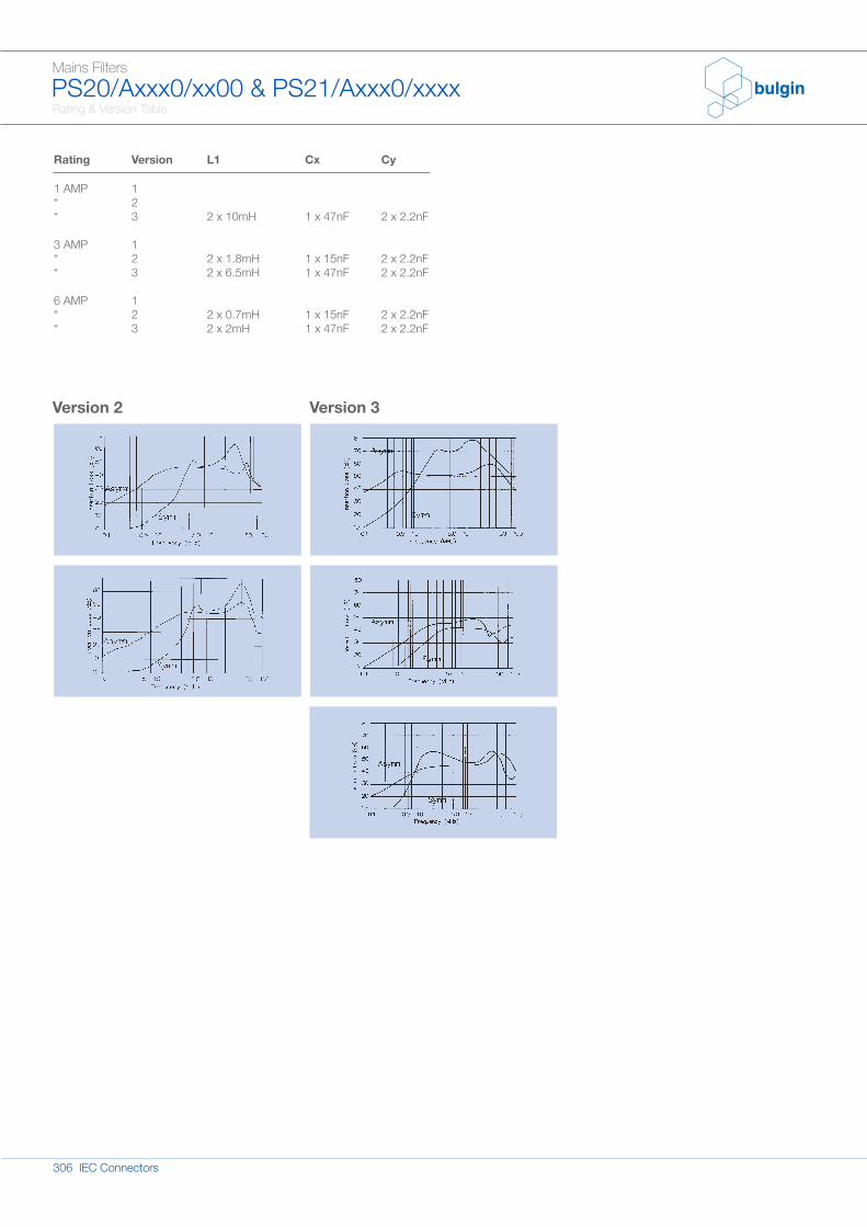
Rating & Version Table
Mains FiltersPS20/Axxx0/xx00 & PS21/Axxx0/xxxx
Version 2 Version 3
Rating
1 AMP““
3 AMP““
6 AMP““
Version
123
123
123
L1
2 x 10mH
2 x 1.8mH2 x 6.5mH
2 x 0.7mH2 x 2mH
Cx
1 x 47nF
1 x 15nF1 x 47nF
1 x 15nF1 x 47nF
Cy
2 x 2.2nF
2 x 2.2nF2 x 2.2nF
2 x 2.2nF2 x 2.2nF
IEC Connectors 307
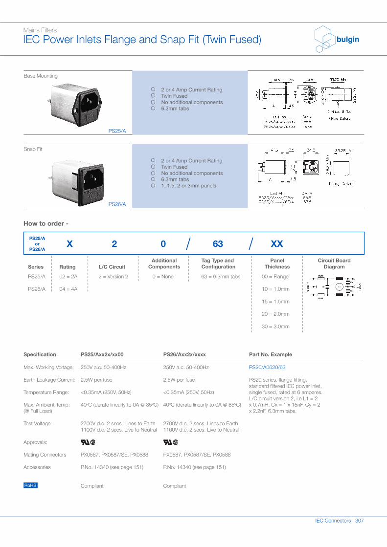
Mains FiltersIEC Power Inlets Flange and Snap Fit (Twin Fused)
Base Mounting
Snap Fit
PS25/A
PS26/A
2 or 4 Amp Current RatingTwin FusedNo additional components6.3mm tabs
2 or 4 Amp Current RatingTwin FusedNo additional components6.3mm tabs1, 1.5, 2 or 3mm panels
Specification
Max. Working Voltage:
Earth Leakage Current:
Temperature Range:
Max. Ambient Temp:(@ Full Load)
Test Voltage:
Approvals:
Mating Connectors
Accessories
RoHS
PS25/Axx2x/xx00
250V a.c. 50-400Hz
2.5W per fuse
<0.35mA (250V, 50Hz)
40ºC (derate linearly to 0A @ 85ºC)
2700V d.c. 2 secs. Lines to Earth1100V d.c. 2 secs. Live to Neutral
PX0587, PX0587/SE, PX0588
P.No. 14340 (see page 151)
Compliant
250V a.c. 50-400Hz
2.5W per fuse
<0.35mA (250V, 50Hz)
40ºC (derate linearly to 0A @ 85ºC)
2700V d.c. 2 secs. Lines to Earth1100V d.c. 2 secs. Live to Neutral
PX0587, PX0587/SE, PX0588
P.No. 14340 (see page 151)
Compliant
PS26/Axx2x/xxxx Part No. Example
PS20/A0620/63
PS20 series, flange fitting,standard filtered IEC power inlet,single fused, rated at 6 amperes.L/C circuit version 2, i.e L1 = 2x 0.7mH, Cx = 1 x 15nF, Cy = 2x 2.2nF. 6.3mm tabs.
How to order -
PS25/A
PS26/A
Series Rating L/C CircuitAdditional
ComponentsTag Type andConfiguration
Panel Thickness
Circuit Board Diagram
02 = 2A
04 = 4A
2 = Version 2 0 = None 63 = 6.3mm tabs 00 = Flange
10 = 1.0mm
15 = 1.5mm
20 = 2.0mm
30 = 3.0mm
X 2 0 63 XXPS25/A
or PS26/A
308 IEC Connectors
Rating & Version Table
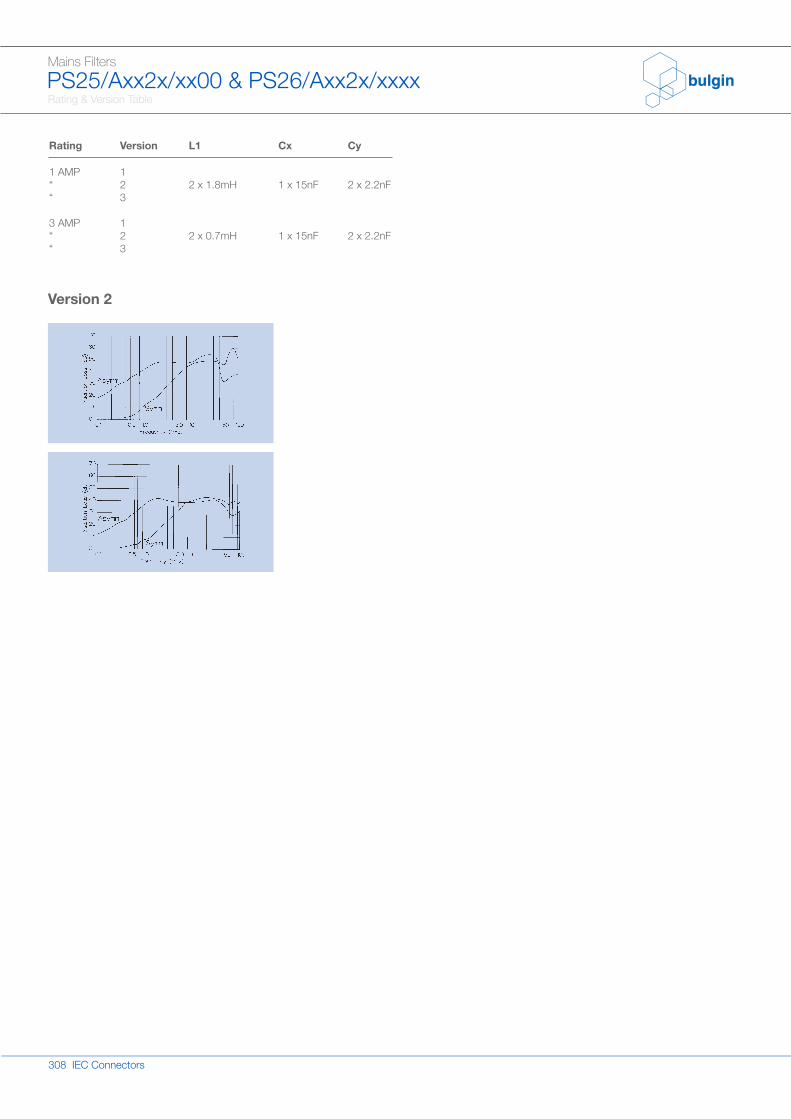
Mains FiltersPS25/Axx2x/xx00 & PS26/Axx2x/xxxx
Version 2
Rating
1 AMP““
3 AMP““
Version
123
123
L1
2 x 1.8mH
2 x 0.7mH
Cx
1 x 15nF
1 x 15nF
Cy
2 x 2.2nF
2 x 2.2nF