iec contactors and starters 1 - powertronics inc contactors and starters 1.1 ... two frame sizes are...
TRANSCRIPT

Volume 5—Motor Control and Protection CA08100006E—April 2013 www.eaton.com V5-T1-157
1
1
1
1
1
1
1
1
1
1
1
1
1
1
1
1
1
1
1
1
1
1
1
1
1
1
1
1
1
1
1.1IEC Contactors and Starters
XT IEC Power Control
Manual Motor Protectors ContentsDescription Page
Relays and Timers . . . . . . . . . . . . . . . . . . . . . . . . . V5-T1-3
Miniature Controls . . . . . . . . . . . . . . . . . . . . . . . . . V5-T1-18
Contactors and Starters . . . . . . . . . . . . . . . . . . . . V5-T1-35
Thermal Overload Relays . . . . . . . . . . . . . . . . . . . . V5-T1-128
C440/XT Electronic Overload Relay . . . . . . . . . . . V5-T1-141
Manual Motor ProtectorsFeatures and Benefits . . . . . . . . . . . . . . . . . . . V5-T1-158
Standards and Certifications . . . . . . . . . . . . . . V5-T1-158
Product Identification . . . . . . . . . . . . . . . . . . . . V5-T1-159
Catalog Number Selection . . . . . . . . . . . . . . . . V5-T1-160
Product Selection . . . . . . . . . . . . . . . . . . . . . . . V5-T1-161
Accessories . . . . . . . . . . . . . . . . . . . . . . . . . . . V5-T1-164
Technical Data and Specifications . . . . . . . . . . V5-T1-176
Dimensions . . . . . . . . . . . . . . . . . . . . . . . . . . . V5-T1-185
Combination Motor Controllers . . . . . . . . . . . . . . . V5-T1-193
XT Electronic Manual Motor Protector . . . . . . . . . V5-T1-216
Reference Data . . . . . . . . . . . . . . . . . . . . . . . . . . . V5-T1-229
Manual Motor ProtectorsProduct DescriptionEaton’s new XT family of manual motor protectors (MMPs) features a pushbutton or rotary ON/OFF manual disconnect, Class 10 adjustable bimetallic overload relay and fixed magnetic short-circuit trip capability in one compact unit. Two frame sizes are available: Frame B (45 mm) for motors with FLA ratings up to 32A and Frame D (55 mm) covers motor FLA ratings up to 65A.
Application DescriptionThe XTPB and XTPR MMPs can be used in the following applications.
Motor Protective Circuit BreakerIn many countries outside of the United States and Canada, especially Europe, the MMPs are tested and classified as thermal-magnetic circuit breakers for use in motor branch circuits. This can be an important consideration for all companies who export their equipment and machines internationally. Both the XTPB and XTPR conform to IEC/EN 60947 and have the CE Mark.
Manual Motor ProtectorsThe XTPB and XTPR MMPs are UL listed under UL 508 as manual motor protectors. They provide an economical solution for applications requiring simple manual starting and stopping of motors. When used as a manual starter, they are typically installed in an enclosure. Many enclosures are offered as accessories for the MMPs. Separate short-circuit protective devices, such as circuit breakers or fuses, are wired ahead of the MMPs. The short-circuit protective device should be sized per the NEC and should not exceed 400% of the maximum FLA dial setting of the MMP.
Group Motor InstallationsA group motor installation can be defined as more than one motor circuit protected by a single set of fuses or circuit breaker on a motor branch circuit. This eliminates the need for individual fuses or circuit breakers for each motor circuit. Substantial component cost savings, panel space savings and reduced wiring installation time can be achieved in group motor installations.
The MMPs are tested and listed for group installation. If remote operation is required, a magnetic contactor can be wired in series with the MMP.
Article 430.53 of the NEC contains the rules and requirements for group motor installations. Refer to application note AP03402001E for NEC requirement for group motor installation.
Individual Branch Motor ApplicationsA UL 508 Type E self-protected manual combination starter/motor controller consists of a single device possessing four essential elements: disconnect, short circuit protection, motor controller, and motor overload protection. Some MMPs require use of a lineside adapter for this type of approval. When tested as an official combination by UL, this device takes the place of a fuse-starter or breaker-starter, XT Type E MMPs are self-protected, meaning they do not need additional short circuit protection of a fuse or breaker. Type E devices can also be used with a contactor or other types of UL approved controllers. If tested with a contactor, the combination motor controller becomes a Type F device. See Page V5-T1-199 for XTFC Type F devices.

V5-T1-158 Volume 5—Motor Control and Protection CA08100006E—April 2013 www.eaton.com
1
1
1
1
1
1
1
1
1
1
1
1
1
1
1
1
1
1
1
1
1
1
1
1
1
1
1
1
1
1
1.1 IEC Contactors and Starters
XT IEC Power Control
Features and Benefits● ON/OFF rotary handle with
lockout provision● Visible trip indication● Class 10 overload
protection● Phase loss sensitivity● Ambient temperature
compensation to IEC/EN 60947, VDE 0660
● Fixed short-circuit trip—14 times maximum setting of overload FLA dial
● Type 2 coordination per IEC 947
● Identification markers standard on starter faceplate
● Motor applications from 0.1A to 65A
● Built-in heater and magnetic trip elements to protect the motor
● Adjustment dial for setting motor FLA
● DIN rail mount● Terminal types available:
● Screw terminals● Screw (line) and spring
cage (load) terminals● Spring cage terminals
● Accessories include:● Front and side auxiliary
contacts● Trip indicating contacts● Tamperproof cover for
OLR dial● Undervoltage release● Shunt trip● Through-the-door
operators● Enclosures● Three-phase line side
connecting links
Standards and Certifications● CE approved● UL listed File No. E245398● UL 508 group motor and
Type E compliant● IEC/EN 60947● CSA File 229767, Class
3211-05● DIN VDE 0660 Part 100,
Part 101 and Part 102
Note: For Type 2 Coordination of MMCs, see Page V5-T1-230.
Line Side Adapters—When to Use Them
Note: Line side adapters are not required for non-US applications. Most countries outside of the US classify the MMP as a thermal magnetic circuit breaker.
Line Side Adapter (LSA)Required
Manual Motor Protector and Line Side Adapter
Manual Motor Protectors
Self-Protected Manual Combination Starters
Line Side Adapter (LSA)Not required
Group InstallationUpstream SCPD required.
UL 508 Type E Self-Protected Manual Combination Starter
Self-protected. No additional SCPD needed in branch circuit.
Line Side AdapterXTPAXLSA
Line Side AdapterXTPAXLSAD
MMPXTPR…BC1
MMPXTPR…DC1

Volume 5—Motor Control and Protection CA08100006E—April 2013 www.eaton.com V5-T1-159
1
1
1
1
1
1
1
1
1
1
1
1
1
1
1
1
1
1
1
1
1
1
1
1
1
1
1
1
1
1
1.1IEC Contactors and Starters
XT IEC Power Control
Product Identification
NotesBasic Units1 XTPB pushbutton manual motor
protectors (see Page V5-T1-161)Rated operational current up to 25ASwitching capacity 50 kA/415VShort-circuit release, adjustable
0.6–1 x luSingle-phasing sensitive
2 XTPR rotary manual motor protectors (see Page V5-T1-162)
Rated operational current up to 32A, 65A
Switching capacity 150/50 kA/415VShort-circuit release, fixed setting to
14 x luOverload release, adjustable 0.6–1 x luSingle-phasing sensitiveWith screws or spring-loaded
terminals
Mounting Accessories3 Rotary handle mechanism
(see Page V5-T1-167)ON/OFF/tripped switch position indicationLockable door/cover interlockExtendable y plug fit extension shaftHandle latched in switch positionsOptionally also without locking and
door interlock function
Insulated enclosures (see Page V5-T1-171)
Surface mounting, enclosures, IP40,IP55 and IP40 and IP55 front flushmounting enclosure
Mounting/wiring (see Page V5-T1-167)Component adapter for busbar mountingThree-phase commoning link for
side-by-side-mountingMounting kits for rapid mounting of
direct-on-line, reversing and star-delta starters
Add-On Functions4 Voltage releases (see Page V5-T1-166)
Undervoltage releaseShunt releasesWith screws or spring-loaded terminals
5 Standard auxiliary contacts (see Page V5-T1-164)
ON/OFF indicationDifferential fault indication overload/
short-circuit releaseON/OFF for (high capacity) contact
moduleON/OFF for starter combinationWith early-make contactsWith screws or spring-loaded terminals
6 Current limiter (see Page V5-T1-166)Increases the switching capacity of the
10–25A manual motor protectors to100 kA/440V
Can be used for individual groupprotection
4
1
2
3
2
5
6
5
5
6
2

V5-T1-160 Volume 5—Motor Control and Protection CA08100006E—April 2013 www.eaton.com
1
1
1
1
1
1
1
1
1
1
1
1
1
1
1
1
1
1
1
1
1
1
1
1
1
1
1
1
1
1
1.1 IEC Contactors and Starters
XT IEC Power Control
Catalog Number Selection
XT Manual Motor Protectors
XT PR 012 B C1
TypePB = Manual motor protector—
pushbuttonPR = Manual motor protector—
rotaryPM = Manual motor protector—
magnetic onlyPT = Manual transformer
protector (high mag.)
DesignationXT = XT IEC power control
Trip ClassC1 = Class 10Blank = Magnetic only (no thermal trip)
Frame SizeB = 45 mmD = 55 mm
Current RatingsFrame BP16 = 0.16AP25 = 0.25AP40 = 0.40AP63 = 0.63A001 = 1A1P6 = 1.6A2P5 = 2.5A004 = 4A6P3 = 6.3A010 = 10A012 = 12A016 = 16A020 = 20A025 = 25A032 = 32A
Frame D016 = 16A025 = 25A032 = 32A040 = 40A050 = 50A058 = 58A063 = 63A

Volume 5—Motor Control and Protection CA08100006E—April 2013 www.eaton.com V5-T1-161
1
1
1
1
1
1
1
1
1
1
1
1
1
1
1
1
1
1
1
1
1
1
1
1
1
1
1
1
1
1
1.1IEC Contactors and Starters
XT IEC Power Control
Product Selection
Product Selection for Manual Motor Starter ApplicationsWhen ordering, specify catalog numbers according to the following stipulations:
XT manual motor protectors are selected based on the overload current range required for a given motor. This current range is determined from the motor full load ampere rating and motor service factor usually found on the motor nameplate.
For motors with service factors less than 1.15, multiply the motor FLA by 0.90 to select appropriate MMP.
Example: For motor having FLA of 6.4A and service factor of 1.0 (6.4A x 0.90 = 5.76A) select catalog number XTPB6P3B01.
See Application Note—AP03402001E.
For motor with service factor of 1.15 or greater, use motor nameplate full load amperes to select the appropriate MMP.
Example: For motor having FLA of 11A and service factor of 1.15, select catalog number XTPR012BC1.
XTPB Pushbutton Manual Motor Protectors—Global and North American Ratings—Frame BType 1 and Type 2 Coordination Motor Protective Device with Thermal and Magnetic Trip
NotesSingle-phasing sensitivity to IEC/EN 60947-4-1, VDE 0660 Part 102.
Can be snap-fit to IEC/EN 60715 top-hat (DIN) with 7.5 or 15 mm height.
Service Factor (SF)—Setting Ir of current scale in dependence of load factor:SF = 1.15 → Ir = 1 x In mot SF = 1 → Ir = 0.9 x In mot
For manual motor protective circuit breaker switching capacity, see Page V5-T1-181. 1 Select manual motor protectors by full load amperes. Maximum motor ratings (kW, hp) are for reference only.2 In this range, calculate motor rating according to rated current. Specified values to NEC 430.6(A)(1).
RatedUninterruptedCurrent—Iu = Ie (Amps)
FLAAdjustmentRange/OverloadRelease—Ir (Amps)
ShortCircuitRelease—Irm (Amps)
Screw TerminalCatalog Number
Maximum Motor Ratings 1
Maximum kW Rating AC-3—P (kW)
Maximum hp Rating—P (hp)UL 508/CSA C22.2 No. 14
Three-Phase Three-Phase
220–240V
380–415V 440V 500V
660–690V 200V 240V 480V 600V
0.16 0.1–0.16 2.2 — — — — 0.06 2 2 2 2 XTPBP16BC1
0.25 0.16–0.25 3.5 — 0.06 0.06 0.06 0.12 2 2 2 2 XTPBP25BC1
0.4 0.25–0.4 5.6 0.06 0.09 0.12 0.12 0.18 2 2 2 2 XTPBP40BC1
0.63 0.4–0.63 8.8 0.09 0.12 0.18 0.25 0.25 2 2 2 2 XTPBP63BC1
1 0.63–1 14 0.12 0.25 0.25 0.37 0.55 2 2 2 1/2 XTPB001BC1
1.6 1–1.6 22 0.25 0.55 0.55 0.75 1.1 2 2 3/4 3/4 XTPB1P6BC1
2.5 1.6–2.5 35 0.37 0.75 1.1 1.1 1.5 1/2 1/2 1 1-1/2 XTPB2P5BC1
4 2.5–4 56 0.75 1.5 1.5 2.2 3 3/4 3/4 2 3 XTPB004BC1
6.3 4–6.3 88 1.1 2.2 3 3 4 1 1-1/2 3 5 XTPB6P3BC1
10 6.3–10 140 2.2 4 4 4 7.5 3 3 7-1/2 10 XTPB010BC1
12 8–12 168 3 5.5 5.5 5.5 11 3 3 7-1/2 10 XTPB012BC1
16 10–16 224 4 7.5 9 9 12.5 3 5 10 10 XTPB016BC1
20 16–20 280 5.5 9 11 12.5 15 5 — — 15 XTPB020BC1
25 20–25 350 5.5 12.5 12.5 15 22 — 7-1/2 15 20 XTPB025BC1
Frame B

V5-T1-162 Volume 5—Motor Control and Protection CA08100006E—April 2013 www.eaton.com
1
1
1
1
1
1
1
1
1
1
1
1
1
1
1
1
1
1
1
1
1
1
1
1
1
1
1
1
1
1
1.1 IEC Contactors and Starters
XT IEC Power Control
XTPR Rotary Manual Motor Protectors with Screw Terminals—Global Ratings and North American Ratings—Frame BType 1 and Type 2 Coordination Motor Protective Device with Thermal and Magnetic Trip
XTPR Rotary Manual Motor Protectors with Screw Terminals—Global Ratings and North American Ratings—Frame DType 1 and Type 2 Coordination Motor Protective Device with Thermal and Magnetic Trip
NotesSingle-phasing sensitivity to IEC/EN 60947-4-1, VDE 0660 Part 102.
Can be snap-fit to IEC/EN 60715 top-hat (DIN) with 7.5 or 15 mm height.
Service Factor (SF)—Setting Ir of current scale in dependence of load factor:SF = 1.15 → Ir = 1 x In mot SF = 1 → Ir = 0.9 x In mot
For manual motor protective circuit breaker switching capacity, see Page V5-T1-181. 1 Select manual motor protectors by full load amperes. Maximum motor ratings (kW, hp) are for reference only.2 In this range, calculate motor rating according to rated current. Specified values to NEC 430.6(A)(1).
RatedUninterruptedCurrent—Iu = Ie (Amps)
FLAAdjustmentRange/OverloadRelease—Ir (Amps)
ShortCircuitRelease—Irm (Amps)
Screw TerminalCatalog Number
Maximum Motor Ratings 1
Maximum kW Rating AC-3—P (kW)
Maximum hp Rating—P (hp)UL 508/CSA C22.2 No. 14
Three-Phase Three-Phase
220–240V
380–415V 440V 500V
660–690V 200V 240V 480V 600V
0.16 0.1–0.16 2.2 — — — — 0.06 2 2 2 2 XTPRP16BC1
0.25 0.16–0.25 3.5 — 0.06 0.06 0.06 0.12 2 2 2 2 XTPRP25BC1
0.4 0.25–0.4 5.6 0.06 0.09 0.12 0.12 0.18 2 2 2 2 XTPRP40BC1
0.63 0.4–0.63 8.8 0.09 0.12 0.18 0.25 0.25 2 2 2 2 XTPRP63BC1
1 0.63–1 14 0.12 0.25 0.25 0.37 0.55 2 2 2 2 XTPR001BC1
1.6 1–1.6 22 0.25 0.55 0.55 0.75 1.1 2 2 3/4 3/4 XTPR1P6BC1
2.5 1.6–2.5 35 0.37 0.75 1.1 1.1 1.5 1/2 1/2 1 1-1/2 XTPR2P5BC1
4 2.5–4 56 0.75 1.5 1.5 2.2 3 3/4 3/4 2 3 XTPR004BC1
6.3 4–6.3 88 1.1 2.2 3 3 4 1 1-1/2 3 5 XTPR6P3BC1
10 6.3–10 140 2.2 4 4 4 7.5 3 3 7-1/2 10 XTPR010BC1
12 8–12 168 3 5.5 5.5 5.5 11 3 3 7-1/2 10 XTPR012BC1
16 10–16 224 4 7.5 9 9 12.5 3 5 10 10 XTPR016BC1
20 16–20 280 5.5 9 11 12.5 15 5 — — 15 XTPR020BC1
25 20–25 350 5.5 12.5 12.5 15 22 — 7-1/2 15 20 XTPR025BC1
32 25–32 448 7.5 15 15 22 30 7-1/2 10 20 25 XTPR032BC1
RatedUninterruptedCurrent—Iu = Ie (Amps)
FLAAdjustmentRange/OverloadRelease—Ir (Amps)
ShortCircuitRelease—Irm (Amps)
Screw TerminalCatalog Number
Maximum Motor Ratings 1
Maximum kW Rating AC-3—P (kW)
Maximum hp Rating—P (hp)UL 508/CSA C22.2 No. 14
Three-Phase Three-Phase
220–240V
380–415V 440V 500V
660–690V 200V 240V 480V 600V
16 10–16 224 4 7.5 9 9 12.5 3 5 10 15 XTPR016DC1
25 16–25 350 5.5 12.5 12.5 15 22 7-1/2 7-1/2 20 25 XTPR025DC1
32 25–32 448 7.5 15 17.5 22 22 10 10 25 30 XTPR032DC1
40 32–40 560 11 20 22 24 30 10 15 30 30 XTPR040DC1
50 40–50 700 14 25 30 30 45 10 15 30 40 XTPR050DC1
58 50–58 812 17 30 37 37 55 15 15 40 50 XTPR058DC1
65 55–65 882 18.5 34 37 45 55 15 15 40 50 XTPR063DC1
Frame B
Frame D

Volume 5—Motor Control and Protection CA08100006E—April 2013 www.eaton.com V5-T1-163
1
1
1
1
1
1
1
1
1
1
1
1
1
1
1
1
1
1
1
1
1
1
1
1
1
1
1
1
1
1
1.1IEC Contactors and Starters
XT IEC Power Control
XTPR Manual Self-Protected Motor Starters—North American Ratings, UL 508 Type E—Frame B 1
Motor Protective Device with Thermal and Magnetic Trip
XTPR Manual Self-Protected Motor Starters—North American Ratings, UL 508 Type E—Frame D 1
Motor Protective Device with Thermal and Magnetic Trip
NotesA UL 508 Type E self-protected manual combination starter (XTPR) consists of a manual motor protector (XTPR) and a UL Listed line side adapter (for example, XTPAXLSA). The Type E self-protected manual combination starter alone is a legitimate short-circuit protective device and disconnect means for the downstream motor, while the contactor has been added to provide remote operation of the motor circuit. Conductor size for XTPAXLSA is 14–6 AWG, XTPAXLSAD is 8 AWG–1/0.1 UL 508 Type E starters are assembled from a standard XTPR and a special incoming terminal line side adapter (XTPAXLSA or XTPAXLSAD).2 Select manual motor protectors by full load amperes. Maximum motor ratings (kW, hp) are for reference only.3 In this range, calculate motor rating according to rated current. Specified values to NEC 430.6(A)(1).
RatedUninterruptedCurrent—Iu (Amps)
FLAAdjustmentRange/OverloadRelease—Ir (Amps)
ShortCircuitRelease—Irm (Amps) Line Side
Adapter 1Catalog Number
Manual MotorProtector—Screw TerminalCatalog Number
Maximum Motor Ratings 2
Maximum hp Rating—P (hp)Three-Phase
Rated Short-CircuitBreaking Capacity (kA)
200V 240V480V/277V
600V/247V
480/277V
600/347V
0.16 0.1–0.16 2.2 3 3 1/2 1/2 50 50 XTPAXLSA XTPRP16BC1
0.25 0.16–0.25 3.4 3 3 1/2 1/2 50 50 XTPAXLSA XTPRP25BC1
0.4 0.25–0.4 5.6 3 3 1/2 1/2 50 50 XTPAXLSA XTPRP40BC1
0.63 0.4–0.63 8.8 3 3 1/2 1/2 50 50 XTPAXLSA XTPRP63BC1
1 0.63–1 14 3 3 1/2 1/2 50 50 XTPAXLSA XTPR001BC1
1.6 1–1.6 22 3 3 3/4 3/4 50 50 XTPAXLSA XTPR1P6BC1
2.5 1.6–2.5 35 1/2 1/2 1 1-1/2 50 50 XTPAXLSA XTPR2P5BC1
4 2.5–4 56 3/4 1 2 3 50 50 XTPAXLSA XTPR004BC1
6.3 4–6.3 88 1 1-1/2 3 5 65 50 XTPAXLSA XTPR6P3BC1
10 6.3–11 140 3 3 7-1/2 10 65 50 XTPAXLSA XTPR010BC1
12 8–12 168 3 3 7-1/2 — 65 — XTPAXLSA XTPR012BC1
16 10–16 224 3 5 10 — 42 — XTPAXLSA XTPR016BC1
20 16–20 280 5 5 — — 18 — XTPAXLSA XTPR020BC1
25 20–25 350 5 7-1/2 15 — 18 — XTPAXLSA XTPR025BC1
32 25–32 448 7-1/2 10 25 — 18 — XTPAXLSA XTPR032BC1
RatedUninterruptedCurrent—Iu (Amps)
FLAAdjustmentRange/OverloadRelease—Ir (Amps)
ShortCircuitRelease—Irm (Amps) Line Side
Adapter 1Catalog Number
Manual MotorProtector—Screw TerminalCatalog Number
Maximum Motor Ratings 2
Maximum hp Rating—P (hp)Three-Phase
Rated Short-CircuitBreaking Capacity (kA)
200V 240V480V/277V
600V/247V 240V
480/277V
600/347V
16 10–16 224 3 5 10 10 65 65 25 XTPAXLSAD XTPR016DC1
25 16–25 350 7-1/2 7-1/2 20 25 65 65 25 XTPAXLSAD XTPR025DC1
32 25–32 448 10 10 25 30 65 65 25 XTPAXLSAD XTPR032DC1
40 32–40 560 10 — 30 30 65 65 25 XTPAXLSAD XTPR040DC1
50 40–50 700 — 15 30 — 65 65 — XTPAXLSAD XTPR050DC1
58 50–58 812 — — 40 — 65 65 — XTPAXLSAD XTPR058DC1
65 55–65 882 — — 40 — 65 65 — XTPAXLSAD XTPR063DC1
Frame B
Frame D

V5-T1-164 Volume 5—Motor Control and Protection CA08100006E—April 2013 www.eaton.com
1
1
1
1
1
1
1
1
1
1
1
1
1
1
1
1
1
1
1
1
1
1
1
1
1
1
1
1
1
1
1.1 IEC Contactors and Starters
XT IEC Power Control
Accessories
Auxiliary Contacts
Side-Mount Auxiliary Contacts
Can be fitted on the right side of manual motor protectors (XTPB, XTPR, XTPM) and manual transformer protectors (XTPT) and can be combined with XTPAXSATR_ and XTPAXFA_ trip indicating auxiliary contact.
Front-Mount Auxiliary Contacts
Can be fitted to manual motor protectors (XTPB, XTPR, XTPM) and manual transformer protectors (XTPT). 45 mm (XTPR…B and XTPB) or 55 mm (XTPR…D) widths of manual motor protectors remain unchanged.
Note1 Orders must be placed in multiples of package quantity listed.
ContactConfiguration Contact Sequence
Pkg. Qty. 1
Screw TerminalCatalog Number
1NO-1NC 5 XTPAXSA11
1NO-2NC 5 XTPAXSA12
2NO-1NC 5 XTPAXSA21
ContactConfiguration Contact Sequence
Pkg. Qty. 1
Screw TerminalCatalog Number
1NO-1NC 5 XTPAXFA11
XTPAXSA_
L1 L2 L3
XTPAXSA11
1.14 1.22
1.13 1.21
1.14 1.22 1.32
1.13 1.21 1.31
L1 L2 L3
XTPAXSA12
1.14 1.22 1.34
1.13 1.21 1.33
L1 L2 L3
XTPAXSA21
XTPAXFA11
1.54 1.62
1.53 1.61
L1 L2 L3
XTPAXFA11

Volume 5—Motor Control and Protection CA08100006E—April 2013 www.eaton.com V5-T1-165
1
1
1
1
1
1
1
1
1
1
1
1
1
1
1
1
1
1
1
1
1
1
1
1
1
1
1
1
1
1
1.1IEC Contactors and Starters
XT IEC Power Control
Side-Mount Trip Indicating Auxiliary Contacts
Can be fitted on the right side of manual motor protectors. Can be combined with standard auxiliary contacts. Trip indication: A. General trip indication (overload) B. Short-circuit trip. Local short-circuit indication by red indicator, manually resettable.
Early-Make Front-Mount Auxiliary Contacts
For use with XTPB_, Frame B XTPR and XTPT. Can be fitted to the front of a manual motor protector. 45 mm width of manual motor protector remains unchanged. For early energization of undervoltage release, for example, in emergency-stop circuits to EN 60204.
Notes1 Orders must be placed in multiples of package quantity listed.2 Not for use with rotary handle mechanism.
ContactConfiguration Contact Sequence
Pkg.Qty. 1
For Use with… Catalog Number
2 x 1NO 2 XTPB, XTPR, XTPM, XTPT
XTPAXSATR20
2 x 1NC 2 XTPB, XTPR, XTPM, XTPT
XTPAXSATR02
ContactConfiguration Contact Sequence
Pkg.Qty. 1
For Use with… Catalog Number
2NO 5 XTPB XTPBXFAEM20
2NO 2 XTPR, XTPM, XTPT
XTPAXFAEM20 2
XTPAXSATR_
4.44 4.14
“+”4.43
“ ”4.13
“+”“ >”
On/Off
“+”“ >”
Trip “+”
L1L2L3
L1L2L3
4.32 4.22
“+”4.31
“ ”4.21
On/Off
“+”“ >”
Trip “+”
L1L2L3
“+”“ >”
L1L2L3
XTPBXFAEM20
XTPAXFAEM20
3.14 3.24
3.13 3.23

V5-T1-166 Volume 5—Motor Control and Protection CA08100006E—April 2013 www.eaton.com
1
1
1
1
1
1
1
1
1
1
1
1
1
1
1
1
1
1
1
1
1
1
1
1
1
1
1
1
1
1
1.1 IEC Contactors and Starters
XT IEC Power Control
Additional Accessories
Shunt Release
Can be used to trip the manual motor protector from a remote location. Can be fitted on the left side of manual motor protectors. Cannot be combined with the XTPAXUVR. DC: Intermittent operation 5 sec.
Undervoltage Release
Can be used to trip the manual motor protector from a remote location. Can be fitted on left side manual motor protectors. Cannot be combined with XTPAXSR. When combined with a circuit breaker, it can be used as emergency-stop device to IEC/EN 60204.
Current Limiter 2
The XTPAXCL enhances the switching capacity of the XT manual motor protectors. It can be used with the XTPB, XTPR…BC1, XTPR…DC1 for individual or group protections. The rated uninterrupted current is 63A for IEC and 25A for UL/CSA. It can be mounted next to or behind the manual motor protector. See Page V5-T1-181 for ratings when using the current limiter.
Notes1 Orders must be placed in multiples of package quantity listed.2 Max. rated operation voltage Ue = 690V, rated uninterrupted current Iu = 63A. Can be used for individual and
group protection. For group protection and in combination with the XTPR…D order additional XTPAXIT incoming terminal if required. Mounting next to or behind the manual motor protector. 16–63A XTPR…D: 100 kA/400V, 10 kA/690V.
Pkg.Qty. 1
Screw TerminalCatalog Number
2 XTPAXSR24V50H
2 XTPAXSR48V50H
2 XTPAXSR110V50H
2 XTPAXSR120V60H
2 XTPAXSR208V60H
2 XTPAXSR220V50H
2 XTPAXSR230V50H
2 XTPAXSR240V50H
2 XTPAXSR240V60H
2 XTPAXSR380V50H
2 XTPAXSR400V50H
2 XTPAXSR415V50H
2 XTPAXSR440V60H
2 XTPAXSR480V60H
2 XTPAXSR24VDC
2 XTPAXSR48VDC
2 XTPAXSR60VDC
2 XTPAXSR110VDC
2 XTPAXSR125VDC
2 XTPAXSR220VDC
2 XTPAXSR250VDC
XTPAXSR_
Contact Sequence
C1
C2
Pkg.Qty. 1
Screw TerminalCatalog Number
2 XTPAXUVR24V50H
2 XTPAXUVR24V60H
2 XTPAXUVR48V50H
2 XTPAXUVR60V50H
2 XTPAXUVR110V50H
2 XTPAXUVR120V60H
2 XTPAXUVR208V60H
2 XTPAXUVR220V50H
2 XTPAXUVR230V50H
2 XTPAXUVR240V50H
2 XTPAXUVR240V60H
2 XTPAXUVR380V50H
2 XTPAXUVR400V50H
2 XTPAXUVR415V50H
2 XTPAXUVR440V60H
2 XTPAXUVR480V60H
2 XTPAXUVR600V60H
XTPAXUVR_
Contact Sequence
D1
D2
U
DescriptionContactSequence
Pkg.Qty. 1 Catalog Number
To enhance the switching capacity of non-inherently safe 10–25A manual motor protectors to 150 kA/440V
1 XTPAXCL
XTPAXCL
L
T

Volume 5—Motor Control and Protection CA08100006E—April 2013 www.eaton.com V5-T1-167
1
1
1
1
1
1
1
1
1
1
1
1
1
1
1
1
1
1
1
1
1
1
1
1
1
1
1
1
1
1
1.1IEC Contactors and Starters
XT IEC Power Control
IP65 Rotary Handle Mechanism 1234
Sealing Facility
Three-Phase Commoning Links 8
For parallel power feed to several manual motor protectors on terminals 1, 3 and 5.
Notes1 Plug-in connection shafts, XTPAXRHMSFT_ can be cut to desired length for mounting depths of 100–240 mm. Carrier
with extension shaft included.2 With ON/OFF switch position and “+” (tripped), lockable with 3 padlocks, 4–8 mm hasp. Can be locked in the
OFF position, if required.3 Rotary handle mechanisms ship with door interlock disabled. See instruction publication with product for how to
enable door interlock.4 Not for use with XTPAXFAEM20 early-make front-mount auxiliary contact.5 Orders must be placed in multiples of package quantity listed. 6 For use on main switches to IEC/EN 60204.7 For use on main switches with emergency-stop function to IEC/EN 60204.8 Protected against accidental contact. Frame B short-circuit proof Ue = 690V, Iu = 63A. Frame B links can be combined by
rotating mounting.
DescriptionEnclosure Rating
Pkg. Qty. 5 Catalog Number
Complete Kits—Includes Handle, Shaft and Required Hardware
Rotary handle mechanism—black 6 IP65NEMA 12UL/CSA 4X
1 XTPAXRHMB
Rotary handle mechanism—red/yellow 7 1 XTPAXRHMRY
Rotary handle mechanism—black—rotated 90° from vertical 6 1 XTPAXRHM90B
Rotary handle mechanism—red/yellow—rotated 90° from vertical 7
1 XTPAXRHM90RY
Separate Parts
Shaft only—includes shaft to mount to XTPR, 175 mm length — 10 XTPAXRHMSFT
DescriptionPkg. Qty. 5 Catalog Number
To prevent tampering with the overload release and the test function. It can be sealed using industry standard sealing wire. For use with XTPR manual motor protectors.
5 XTPAXSW
For Use with…Qty. MMP
MMP Frame Size
Pkg.Qty. 5 Catalog Number
MMP with no side-mounted auxiliaries or voltage releases
2 B 10 XTPAXCLKA2
D 1 XTPAXCLKA2D
3 B 10 XTPAXCLKA3
D 1 XTPAXCLKA3D
4 B 10 XTPAXCLKA4
D 1 XTPAXCLKA4D
5 B 10 XTPAXCLKA5
Each MMP with one auxiliary contact or trip-indicating auxiliary contact fitted on the right
2 B 10 XTPAXCLKB2
D 1 XTPAXCLKB2D
3 B 10 XTPAXCLKB3
D 1 XTPAXCLKB3D
4 B 10 XTPAXCLKB4
D 1 XTPAXCLKB4D
5 B 10 XTPAXCLKB5
Each MMP with an auxiliary contact and trip-indicating auxiliary contact mounted on the right or a voltage release mounted on the left.
2 B 10 XTPAXCLKC2
4 D 1 XTPAXCLKC4D
XTPAXRHM_
XTPAXRHMSFT
XTPAXSW

V5-T1-168 Volume 5—Motor Control and Protection CA08100006E—April 2013 www.eaton.com
1
1
1
1
1
1
1
1
1
1
1
1
1
1
1
1
1
1
1
1
1
1
1
1
1
1
1
1
1
1
1.1 IEC Contactors and Starters
XT IEC Power Control
Shroud for Unused Terminals of Three-Phase Commoning Links
Incoming Terminals for Three-Phase Commoning Link 2
Line-Side Adapter 3
Combination Connection Kits
Non-Reversing Starters
Notes1 Orders must be placed in multiples of package quantity listed.2 For three-phase commoning link, protected against accidental contact, Ue = 690V, Iu = 63A;
For conductor cross-sections: 2.5–25 mm2 stranded; 2.5–16 mm2 flexible with ferrules, AWG 14-6.3 XTPAXLSA is for three-phase commoning link, finger and back-of-hand proof,
Ue = 690V, Iu = 60A for conductor cross sections: 2.5–25 mm2 stranded, 2.5–16 mm2 flexible with ferrule, AWG 14-6.
4 XTPAXLSAD cannot be combined with three-phase commoning links. Conductor size 8 AWG–1/0.
For Use with… DescriptionPkg.Qty. 1 Catalog Number
Frame BXTPR
To cover unused terminals on three-phase commoning link. Protected against direct contact.
20 XTPAXUTS
For Use with…Pkg.Qty. 1 Catalog Number
Frame B XTPR, XTPB 5 XTPAXIT
For Use with…Pkg.Qty. 1 Catalog Number
Frame B XTPR to create a UL 508 Type E/F manual combination starter
5 XTPAXLSA
Frame D XTPR to create a UL 508 Type E/F manual combination starter
1 XTPAXLSAD 4
For Use with… Description/Comprised of …Std. Pack 1 Catalog Number
XTPR…B + XTCE…B Mechanical connection element for XTPR…B and contactor 1 XTPAXTPCB
Main current wiring between XTPR…B and contactor in toolless plug connection 1
Use contactor auxiliary switch XTCEXFAT_. Control cable guidance: max. six cables up to 2.5 mm2 external diameter or four cables up to 3.5 mm2 external diameter.
XTPR…B + XTCE…C DIN rail adapter plateMain current wiring between XTPR and contactor
1 XTPAXTPCC
XTPR…D + XTCE…D DIN rail adapter plateMain current wiring between XTPR and contactor
1 XTPAXTPCD
XTPAXUTS
XTPAXIT
XTPAXLSA
XTPAXLSAD
XTPAXTPCB
XTPAXTPC_

Volume 5—Motor Control and Protection CA08100006E—April 2013 www.eaton.com V5-T1-169
1
1
1
1
1
1
1
1
1
1
1
1
1
1
1
1
1
1
1
1
1
1
1
1
1
1
1
1
1
1
1.1IEC Contactors and Starters
XT IEC Power Control
Reversing Starters
Note1 Orders must be placed in multiples of package quantity listed.
For Use with… Description/Comprised of …Std. Pack 1 Catalog Number
XTPR…B + XTCE…B01_ Mechanical connection element for XTPR…B and contactor 1 XTPAXTPCRB
Reversing starter main current wiring in toolless plug connection 1
Control cables for electrical interlocking in toolless plug connection:– K1M: A1–K2M: 21– K1M: 21–K2M: A1– K1M: A2–K2M: A2
1
Cable guidance 1
Use contactor auxiliary switch XTCEXFAT_. Control cable guidance: max. six cables up to 2.5 mm2 external diameter or four cables up to 3.5 mm2 external diameter.
XTPR…B + XTCE…C DIN rail adapter plate 1 XTPAXTPCRC
Reversing starter main current wiring 1
XTPAXTPCRB
XTPAXTPCRC

V5-T1-170 Volume 5—Motor Control and Protection CA08100006E—April 2013 www.eaton.com
1
1
1
1
1
1
1
1
1
1
1
1
1
1
1
1
1
1
1
1
1
1
1
1
1
1
1
1
1
1
1.1 IEC Contactors and Starters
XT IEC Power Control
Electrical Connection Module
DIN Rail Adapter Plates
Note1 Orders must be placed in multiples of package quantity listed.
For Use with… Description/Comprised of …Std. Pack 1 Catalog Number
XTPR…B + XTCE…C Main current wiring between XTPR…B and contactor 5 XTPAXECMC
XTPR…D + XTCE…D Main current wiring between XTPR…D and contactor 5 XTPAXECMD
For Use with… Description/Comprised of …Std. Pack 1 Catalog Number
XTPAXTPCBXTPAXTPCRB
45 mm wide adapter plate with one DIN rail 4 XTPAXTPCPB
Connection element for side-by-side positioning of further plates
XTPAXECMDXTPR…D + XTCE…CXTPR…D + XTCE…D
55 mm wide adapter plate with two DIN rails 4 XTPAXTPCPD
Connection cams for further plates
For use with reversing and star-delta starters
XTPAXECM_
XTPAXTPCPB
XTPAXTPCPD
Volume 5—Motor Control and Protection CA08100006E—April 2013 www.eaton.com V5-T1-171
1
1
1
1
1
1
1
1
1
1
1
1
1
1
1
1
1
1
1
1
1
1
1
1
1
1
1
1
1
1
1.1IEC Contactors and Starters
XT IEC Power Control
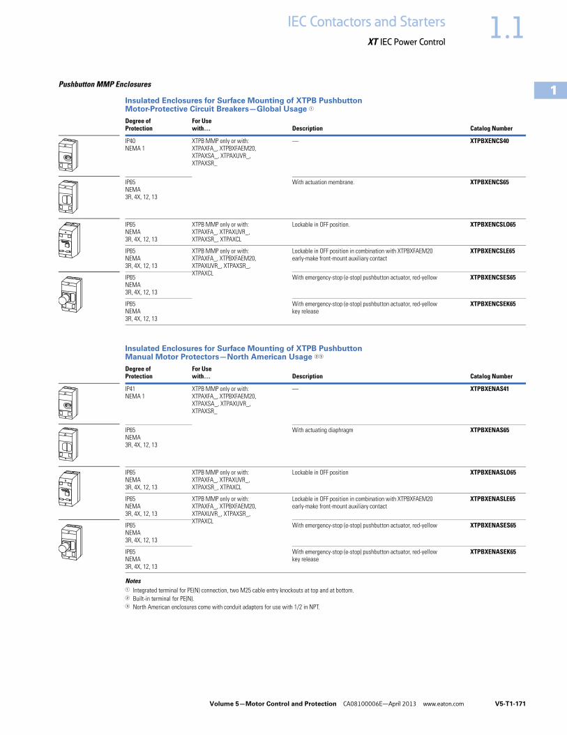
Pushbutton MMP Enclosures
Insulated Enclosures for Surface Mounting of XTPB Pushbutton Motor-Protective Circuit Breakers—Global Usage 1
Insulated Enclosures for Surface Mounting of XTPB Pushbutton Manual Motor Protectors—North American Usage 23
Notes1 Integrated terminal for PE(N) connection, two M25 cable entry knockouts at top and at bottom.2 Built-in terminal for PE(N).3 North American enclosures come with conduit adapters for use with 1/2 in NPT.
Degree ofProtection
For Use with… Description Catalog Number
IP40NEMA 1
XTPB MMP only or with: XTPAXFA_, XTPBXFAEM20, XTPAXSA_, XTPAXUVR_, XTPAXSR_
— XTPBXENCS40
IP65NEMA3R, 4X, 12, 13
With actuation membrane. XTPBXENCS65
IP65NEMA3R, 4X, 12, 13
XTPB MMP only or with: XTPAXFA_, XTPAXUVR_, XTPAXSR_, XTPAXCL
Lockable in OFF position. XTPBXENCSLO65
IP65NEMA3R, 4X, 12, 13
XTPB MMP only or with: XTPAXFA_, XTPBXFAEM20,XTPAXUVR_, XTPAXSR_, XTPAXCL
Lockable in OFF position in combination with XTPBXFAEM20 early-make front-mount auxiliary contact
XTPBXENCSLE65
IP65NEMA3R, 4X, 12, 13
With emergency-stop (e-stop) pushbutton actuator, red-yellow XTPBXENCSES65
IP65NEMA3R, 4X, 12, 13
With emergency-stop (e-stop) pushbutton actuator, red-yellowkey release
XTPBXENCSEK65
Degree ofProtection
For Use with… Description Catalog Number
IP41NEMA 1
XTPB MMP only or with: XTPAXFA_, XTPBXFAEM20, XTPAXSA_, XTPAXUVR_, XTPAXSR_
— XTPBXENAS41
IP65NEMA3R, 4X, 12, 13
With actuating diaphragm XTPBXENAS65
IP65NEMA3R, 4X, 12, 13
XTPB MMP only or with: XTPAXFA_, XTPAXUVR_, XTPAXSR_, XTPAXCL
Lockable in OFF position XTPBXENASLO65
IP65NEMA3R, 4X, 12, 13
XTPB MMP only or with: XTPAXFA_, XTPBXFAEM20,XTPAXUVR_, XTPAXSR_, XTPAXCL
Lockable in OFF position in combination with XTPBXFAEM20 early-make front-mount auxiliary contact
XTPBXENASLE65
IP65NEMA3R, 4X, 12, 13
With emergency-stop (e-stop) pushbutton actuator, red-yellow XTPBXENASES65
IP65NEMA3R, 4X, 12, 13
With emergency-stop (e-stop) pushbutton actuator, red-yellowkey release
XTPBXENASEK65

V5-T1-172 Volume 5—Motor Control and Protection CA08100006E—April 2013 www.eaton.com
1
1
1
1
1
1
1
1
1
1
1
1
1
1
1
1
1
1
1
1
1
1
1
1
1
1
1
1
1
1
1.1 IEC Contactors and Starters
XT IEC Power Control
Insulated Enclosures for Surface Mounting of XTPB Pushbutton Manual Motor Protectors—North American Usage 1
Note1 Integrated terminal for PE(N) connection.
Degree ofProtection
For Use with… Description Catalog Number
Front IP40NEMA 1
XTPB MMP only or with: XTPAXFA_, XTPBXFAEM20, XTPAXSA_, XTPAXUVR_, XTPAXSR_
— XTPBXENCF40
Front IP65NEMA3R, 4X, 12, 13
With actuating diaphragm XTPBXENCF55
Front IP65NEMA3R, 4X, 12, 13
XTPB MMP only or with: XTPAXFA_, XTPAXUVR_, XTPAXSR_, XTPAXCL
Lockable in OFF position XTPBXENCFLO55
Front IP65NEMA3R, 4X, 12, 13
XTPB MMP only or with: XTPAXFA_, XTPBXFAEM20,XTPAXUVR_, XTPAXSR_, XTPAXCL
Lockable in OFF position in combination with XTPBXFAEM20 early-make front-mount auxiliary contact
XTPBXENCFLE55
Front IP65NEMA3R, 4X, 12, 13
With emergency-stop (e-stop) pushbutton actuator, red-yellow XTPBXENCFES55
Front IP65NEMA3R, 4X, 12, 13
With emergency-stop (e-stop) pushbutton actuator, red-yellowkey release
XTPBXENCFEK55

Volume 5—Motor Control and Protection CA08100006E—April 2013 www.eaton.com V5-T1-173
1
1
1
1
1
1
1
1
1
1
1
1
1
1
1
1
1
1
1
1
1
1
1
1
1
1
1
1
1
1
1.1IEC Contactors and Starters
XT IEC Power Control
Rotary MMP Enclosures
Insulated Enclosures for Surface Mounting of Frame B (0.1–32A) XTPR Motor-Protective Circuit Breakers—Global Usage
Insulated Enclosures for Surface Mounting of Frame B (0.1–32A) XTPR Rotary Manual Motor Protectors—North American Usage 3
Insulated Enclosures for Surface Mounting of Frame B XTPR (0.1–32A) Rotary Motor-Protective Circuit Breakers with XTPAXFAEM20 Early-Make Front-Mount Auxiliary Contact—Global Usage
Notes1 M25 metric cable entry knock-out, top and bottom. Cable push-through membrane, top and bottom, in the back plate and as a control line entry.
Includes N and PE terminals.2 Integrated terminal for PE(N) connection, two M25 cable entry knockouts at the top and bottom.3 Built-in N and PE terminal, lower part without knockouts.
Degree ofProtection
For Use with… Description Catalog Number
IP41 with vertical mounting
Frame B XTPR only or with: XTPAXFA_, XTPAXSA_, XTPAXSATR_, XTPAXUVR_, XTPAXSR_, XTPAXCL
Cover with aperture dimensioned to accommodate front of MMP. IP40, when mounted turned through 90° to left/right
XTPAXENCS41 1
IP65 With black/grey rotary handle XTPAXENCS65B 1
IP65 With red/yellow rotary handle for use as emergency-stop switches to IEC/EN 60204
XTPAXENCS65RY 1
IP40 Frame B XTPR only or with: XTPAXSA_, XTPAXUVR_, XTPAXSR_, XTPAXCL
Cover with aperture dimensioned to accommodate front of MMP XTPAXENCS40 2
IP55 Frame B XTPR only or with: XTPAXFA_, XTPAXSA_, XTPAXUVR_, XTPAXSR_, XTPAXCL
With black/gray rotary handle XTPAXENCS55B 2
IP55 With red/yellow rotary handle for use as emergency-stop switches to IEC/EN 60204
XTPAXENCS55RY 2
Degree ofProtection
For Use with… Description Catalog Number
IP55NEMA 1, 12, 3R
Frame B XTPR only or with: XTPAXSA_ and XTPAXFA_, XTPAXUVR_ and XTPAXFA_, XTPAXSR_ and XTPAXFA_, XTPAXCL
With black/gray rotary handle XTPAXENAS55B
With red/yellow rotary handle for use as emergency-stop switch to VDE 0113
XTPAXENAS55RY
Degree ofProtection
For Use with… Description Catalog Number
IP65 Frame B XTPR and XTPAXFAEM20 only or with: XTPAXFA_, XTPAXSA_, XTPAXSATR_, XTPAXUVR_, XTPAXSR_, XTPAXCL
With black/gray rotary handle XTPAXENCSEM65B
IP65 With red/yellow rotary handle for use as emergency-stop switches to IEC/EN 60204
XTPAXENCSEM65RY
IP55 Frame B XTPR and XTPAXFAEM20 only or with: XTPAXFA_, XTPAXUVR_, XTPAXSR_, XTPAXCL
With black/gray rotary handle XTPAXENCSEM55B
IP55 With red/yellow rotary handle for use as emergency-stop switches to IEC/EN 60204
XTPAXENCSEM55RY

V5-T1-174 Volume 5—Motor Control and Protection CA08100006E—April 2013 www.eaton.com
1
1
1
1
1
1
1
1
1
1
1
1
1
1
1
1
1
1
1
1
1
1
1
1
1
1
1
1
1
1
1.1 IEC Contactors and Starters
XT IEC Power Control
Insulated Enclosures for Surface Mounting of Frame B XTPR (0.1–32A) Rotary Manual Motor Protectors with XTPAXFAEM20 Early-Make Front-Mount Auxiliary Contact—North American Usage 1
Insulated Enclosures for Flush Mounting of Frame B (0.1–32A) XTPR Rotary Manual Motor Protectors—Global Usage 2
Insulated Enclosures for Surface Mounting of Frame D (10–65A) Rotary Motor-Protective Circuit Breakers
Notes1 Built-in N and PE terminal, lower part without knockouts.2 Integrated terminal for PE(N) connection.
Degree ofProtection
For Use with… Description Catalog Number
IP55NEMA 1, 12, 3R
Frame B XTPR only or with: XTPAXSA_, XTPAXUVR_, XTPAXCL
With black/grey rotary handle XTPAXENASEM55B
With red/yellow rotary handle for use as emergency-stop switch to VDE 0113
XTPAXENASEM55RY
Degree ofProtection
For Use with… Description Catalog Number
Front IP40 Frame B XTPR only or with: XTPAXSA_, XTPAXUVR_, XTPAXSR_, XTPAXCL
Cover with aperture dimensioned to accommodate front of MMP XTPAXENCF40
Front IP55 Frame B XTPR only or with: XTPAXSA_, XTPAXUVR_, XTPAXSR_, XTPAXFA_, XTPAXCL
With black/gray rotary handle XTPAXENCF55B
With red/yellow rotary handle for use as emergency-stop switches to IEC/EN 60204
XTPAXENCF55RY
Degree ofProtection
For Use with… Description Catalog Number
IP65NEMA 1, 12, 3R, 4X
Frame D XTPR only or with: XTPAXFA_, XTPAXFAEM20, XTPAXSA_, XTPAXSATR_, XTPAXUVR_, XTPAXSR_, XTPAXCL
With black/gray rotary handle XTPAXENCSD65B
IP65NEMA 1, 12, 3R, 4X
With red/yellow rotary handle for use as emergency-stop switches to IEC/EN 60204
XTPAXENCSD65RY

Volume 5—Motor Control and Protection CA08100006E—April 2013 www.eaton.com V5-T1-175
1
1
1
1
1
1
1
1
1
1
1
1
1
1
1
1
1
1
1
1
1
1
1
1
1
1
1
1
1
1
1.1IEC Contactors and Starters
XT IEC Power Control
MMP Enclosure Accessories
XTPR Manual Motor Protector Enclosure Padlock Attachment
Neutral Terminal for Use with XTPB and Frame B XTPR Flush-Mount Enclosures
Indicating Lights with Neon Bulb
For use with XTPR and XTPB enclosures.
Lights do not carry individual IP or NEMA rating. All enclosure ratings remain valid when using indicating lights.
Notes1 Orders must be placed in multiples of package quantity listed. 2 Lockable in the 0-position of the XTPR manual motor protector.3 Lockable in the OFF position of the Frame B XTPR manual motor protector.
For Use with… Description
Pkg.Qty. 1 Catalog Number
XTPAXENCS65B, XTPAXENCS65RY, XTPAXENCSEM65B, XTPAXENCSEM65RY, XTPAXENCS55B, XTPAXENCS55RY, XTPAXENCSEM55B, XTPAXENCSEM55RY
Padlocking feature. Up to three padlocks with 3–6 mm hasp thickness.For use as main switch to IEC/EN 60204
3 XTPAXPL1 2
XTPAXENCSD65B, XTPAXENCSD65RY 1 XTPAXPL2 2
XTPAXENCF55B, XTPAXENCF55RY 3 XTPAXPL3 3
For Use with… Description
Pkg.Qty. 1 Catalog Number
XTPBXENCF40, XTPBXENCF55, XTPAXENCF40, XTPAXENCF55B, XTPAXENCF55RY
For connection of a fifth conductor 20 XTPAXNT
ColorDescription—Indicating Light
Pkg. Qty. 1 Catalog Number
White 110–230V 10 XTPAXILWB
230–400V 10 XTPAXILWN
415–500V 10 XTPAXILWC
Green 110–230V 10 XTPAXILGB
230–400V 10 XTPAXILGN
415–500V 10 XTPAXILGC
Red 110–230V 10 XTPAXILRB
230–400V 10 XTPAXILRN
XTPAXPL_
XTPAXNT
XTPAXIL_

V5-T1-176 Volume 5—Motor Control and Protection CA08100006E—April 2013 www.eaton.com
1
1
1
1
1
1
1
1
1
1
1
1
1
1
1
1
1
1
1
1
1
1
1
1
1
1
1
1
1
1
1.1 IEC Contactors and Starters
XT IEC Power Control
Technical Data and Specifications
XT Manual Motor Protectors
Note1 Damp heat, constant, to IEC 60068-2-78; damp heat, cyclic, to IEC 60068-2-30.
DescriptionXTPBP16B–XTPB025B
XTPRP16B–XTPR032B
XTPR016D–XTPR063D
General
Standards IEC/EN 60947, VDE 0660, UL 508, CSA C22.2 No. 14
IEC/EN 60947, VDE 0660, UL 508, CSA C22.2 No. 14
IEC/EN 60947, VDE 0660, UL 508, CSA C22.2 No. 14
Climatic proofing 1 1 1
Ambient temperature, °C
Storage –25/80 –25/80 –25/70
Open –25/55 –25/55 –25/55
Enclosed –25/40 –25/40 –25/40
Mounting position
Direction of incoming supply As required As required As required
Degree of protection
Device IP20 IP20 IP20
Terminals IP00 IP00 IP00
Protection against direct contact Finger and back-of-hand proof
Finger and back-of-hand proof
Finger and back-of-hand proof
Shock resistance half-sinusoidal shock 10 ms to IEC 60068-2-27 (g)
25 25 15
Altitude (m), maximum 2000 2000 2000
Terminal capacity
Solid (mm2) 1 x (1–6) 2 x (1–6)
1 x (1–6) 2 x (1–6)
1 x (1–50) 2 x (1–35)
Flexible with ferrule to DIN 46228, (mm2) 1 x (1–6) 2 x (1–6)
1 x (1–6) 2 x (1–6)
1 x (1–35) 2 x (1–35)
Solid or stranded (AWG) 18–10 18–10 14–2
Terminal screw tightening torque
Main cable, Nm 1.7 1. 3
Main cable, lb-in 15.0 15.0 26.6
Control circuit cable, Nm 1 1 1
Control circuit cable, lb-in 8.9 8.9 8.9
Main Contacts
Rated impulse withstand voltage (Uimp), Vac 6000 6000 6000
Overvoltage category/pollution degree III/3 III/3 III/3
Rated operational voltage (Ue), Vac 690 690 690
Rated uninterrupted current = rated operational current (Iu = Ie) in amperes
25 or current setting of the overcurrent release
25 or current setting of the overcurrent release
25 or current setting of the overcurrent release
Rated frequency, Hz 40–60 40–60 40–60
Current heat loss (three-pole at operating temperature), W 6 6 22
Lifespan, mechanical (ops) 50,000 100,000 30,000
Lifespan, electrical (AC-3 at 400V) (ops) 50,000 100,000 30,000
Maximum operating frequency, operations/hr 25 40 40
Short-circuit rating
AC See Page V5-T1-181 See Page V5-T1-181 See Page V5-T1-181
DC (kA) 60 60 (up to XTPR016B)40 (XTPR020B–XTPR032B)
60
Motor switching capacity
AC-3 (up to 690V) in amperes 25 32 65
DC-5 (up to 250V) in amperes 25 25 (3 contacts in series) 63 (3 contacts in series)
90 9090
90 9090
90 90

Volume 5—Motor Control and Protection CA08100006E—April 2013 www.eaton.com V5-T1-177
1
1
1
1
1
1
1
1
1
1
1
1
1
1
1
1
1
1
1
1
1
1
1
1
1
1
1
1
1
1
1.1IEC Contactors and Starters
XT IEC Power Control
XT Manual Motor Protectors, continued
Auxiliary Contacts
DescriptionXTPBP16B–XTPB025B
XTPRP16B–XTPR032B
XTPR016D–XTPR063D
Releases
Overload release setting range (x Iu) 0.6–1.0 0.6–1.0 0.6–1.0
Fixed short-circuit release (x Iu) 14 14 14
Short-circuit release tolerance ± 20% ± 20% ± 20%
Phase-failure sensitivity IEC/EN 60947-1-1, VDE 0660 Part 102
IEC/EN 60947-1-1, VDE 0660 Part 102
IEC/EN 60947-1-1, VDE 0660 Part 102
Temperature compensation
to IEC/EN 60947, VDE 0660, °C –5/40 –5/40 –5/40
operating range, °C –25/55 –25/55 –25/55
Temperature compensation residual error for T >20°C, %/K <0.25 <0.25 <0.25
Description XTPAXSA_ _ XTPAXFA_ _ XTPA(B)XFAEM_ _ XTPAXSATR_ _
Rated impulse withstand voltage, Uimp (Vac) 6000 4000 4000 6000
Overvoltage category/pollution degree III/3 III/3 III/3 III/3
Rated operational voltage
Ue (Vac) 500 440 440 500
Ue (Vdc) 250 250 250 250
Safe isolation to VDE 0106 Part 101 andPart 101/A1 between auxiliary contacts and main contacts (Vac)
690 690 690 690
Rated operational current
AC-15
220–240 V, Ie (A) 3.5 1 1 3.5
380–415 V, Ie (A) 2 — — 2
440–500 V, Ie (A) 1 — — 1
DC-13 L/R <100 ms
24 V, Ie (A) 2 2 2 2
60 V, Ie (A) 1.5 — — 1.5
110 V, Ie (A) 1 — — 1
220 V, Ie (A) 0.25 — — 0.25
Lifespan
Mechanical, operations (x 106) 0.1 0.1 0.1 0.01
Electrical, operations (x 106) 0.05 0.1 0.1 0.005
Contact reliability (at Ue = 24 Vdc, Umin–17V, Imin = 5.4 mA, fault probability
<10–8 <1 fault at 1 x 10⁸ operations
<10–8 <1 fault at 1 x 10⁸ operations
<10–8 <1 fault at 1 x 10⁸ operations
<10–8 <1 fault at 1 x 10⁸ operations
Positively driven contacts to ZH 1/457 Yes — — —
Short-Circuit Rating without Welding
Fuseless FAZ-B4/1-HI — — FAZ-B4/1-HI
Fuse (A gG/gL) 10 10 10 10
Terminal Capacity
Solid or flexible conductor with ferrule (mm2) 0.75–2.5 0.75–1.5 0.75–1.5 0.75–2.5
Solid or stranded (AWG) 18–14 18–16 18–16 18–14

V5-T1-178 Volume 5—Motor Control and Protection CA08100006E—April 2013 www.eaton.com
1
1
1
1
1
1
1
1
1
1
1
1
1
1
1
1
1
1
1
1
1
1
1
1
1
1
1
1
1
1
1.1 IEC Contactors and Starters
XT IEC Power Control
Undervoltage Release
Current Limiter
XTPB, XTPR Single- and Two-Pole Circuits with DC and AC Current
Protection of PVC Insulated Cables Against Thermal Overload at Short-Circuit
The chart above indicates which minimum cable cross-sections are protected by XTPR motor protective circuit breakers up to their rated conditional short-circuit current Iq.
Shunt Release
Description XTPAXUVR_
Cross-Section
Solid or flexible conductor with ferrule (mm2) 1 x (0.75–2.5)2 x (0.75–2.5)
Solid or stranded (AWG) 1 x (18–14)2 x (18–14)
Main Contact
Rated operational voltage, Ue (Vac) 42–480
Rated operational voltage, Ue (Vdc) 24–250
Pickup voltage, x Us 0.85–1.1
Dropout voltage, x Us 0.7–0.35
Power Consumption
Pickup AC (VA) 5
Sealing AC (VA) 3
Description XTPAXCL
Rated impulse withstand voltage (Uimp), Vac 6000
Overvoltage category/pollution degree III/3
Rated operational voltage, Ue (Vac) 690
Rated interrupted current = Rated operational current (lu = le) in amperes 63
1 3 5
2 4 6I > I > I >
1 3 5
2 4 6I > I > I >
Description XTPAXSR __
Cross-Section
Solid or flexible conductor with ferrule (mm2) 1 x (0.75–2.5)2 x (0.75–2.5)
Solid or stranded (AWG) 1 x (18–14)2 x (18–14)
Main Contact
Rated operational voltage, Ue (Vac) 42–480
Rated operational voltage, Ue (Vdc) 24–250
AC operating range, x Us 0.7–1.1
DC operating range, x Us (intermittent operation 5s) 0.7–1.1
Power Consumption
Pickup AC (VA) 5
Sealing AC (VA) 3
Pickup DC (VA) 3
Sealing DC (VA) 3
Min. Cross-Section Protected
380-415V, 50 Hz, Cu mm2
Device
Type
4 2.5 1.5 1 0.75
XTPRP16BC1
...
XTPR6P3BC1
XTPR010BC1
XTPR016BC1
XTPR020BC1
XTPR025BC1
XTPR016DC1
XTPR025DC1
XTPR032DC1
XTPR040DC1
XTPR050DC1
XTPR058DC1
XTPR063DC1

Volume 5—Motor Control and Protection CA08100006E—April 2013 www.eaton.com V5-T1-179
1
1
1
1
1
1
1
1
1
1
1
1
1
1
1
1
1
1
1
1
1
1
1
1
1
1
1
1
1
1
1.1IEC Contactors and Starters
XT IEC Power Control
Wiring Diagrams
Fuseless Installation with XTPRBackup Protection Diagram—XTPR…B
Time/Current Curves
Characteristics
The time/current characteristic, the current limiting characteristics and the I2t characteristics were determined in accordance with DIN VDE 0660 and IEC 60 947.
The tripping characteristic of the inverse-time delayed overload releases (thermal overload releases or “a” releases) for DC and AC with a frequency of 0 to 400 Hz also apply to the time/current characteristic.
The characteristics apply to the cold state. At operating temperature, the tripping times of the thermal releases are reduced to approximately 25%.
Under normal operating conditions, all three-poles of the device must be loaded. The three main conducting paths must be connected in series in order to protect single-phase or DC loads.
With three-pole loading, the maximum deviation in the tripping time for 3 times the setting current and upwards is ±20% and thus in accordance with DIN VDE 0165.
The tripping characteristics for the instantaneous, electromagnetic overcurrent releases (short-circuit releases or “n” releases) are based on the rated current In, which is also the maximum value of the setting range for circuit breakers with adjustable overload releases. If the current is set to a lower value, the tripping current of the “n” release is increased by a corresponding factor.
The characteristics of the electromagnetic overcurrent releases apply to frequencies of 50/60 Hz. Appropriate correction factors must be used for lower frequencies up to 16-2/3 Hz, for higher frequencies up to 400 Hz and for DC.
Time/current characteristics, current limiting characteristics and I2t characteristics are available on request.
XTPR…B
XTPR…B
415 VacIn
here
ntl
y s
ho
rt-c
ircu
it p
roo
f Back-up
protectionrangewith XTPAXCL
Ratedshort-circuitbreakingcapacityrange
100
50
30
2016
10
6
0.16... 101620 25 X
TP
R…
B +
XT
PA
XC
LX
TP
R…
B
XTPR...B
RatedCurrent
Inherentlyshort-circuit-proof
cn
cc
n [A]
cc r
ms [
kA
]
Backup Protection Diagram—XTPR…D
MMP Tripping Characteristics
XTPB, XTPR Frame B
XTPR Frame D
100
50
30
2016
10
6
XTPR…D
XTPR…D
Back-upprotectionrange with XTPAXCL
Ratedshort-circuitbreakingcapacityrange
16... 3225 40 50 63
XTPR...D + XTPAXCL
XTPR…D
Inh
ere
ntl
ysh
ort
-cir
cu
it-p
roo
f
415 Vac
Inh
ere
ntl
y s
ho
rt-c
ircu
it p
roo
f
cn
cc
cc r
ms [
kA
]
RatedCurrent
n [A]
RatedCurrent
n [A]
2
5
20
50
200
1
2
5
10
20
401
2
5
10
202h
1.5 2 3 4 6 8 10 15 20 30
XTPB, XTPR Frame B
XTPT
Seco
nd
sM
illi-s
eco
nd
sM
inu
tes
x Rated Operational Current
XTPR Frame D
2
5
20
50
200
1
2
5
10
20
401
2
5
10
202h
1.5 2 3 4 6 8 10 15 20 30
Seco
nd
sM
illi-s
eco
nd
sM
inu
tes
x Rated Operational Current

V5-T1-180 Volume 5—Motor Control and Protection CA08100006E—April 2013 www.eaton.com
1
1
1
1
1
1
1
1
1
1
1
1
1
1
1
1
1
1
1
1
1
1
1
1
1
1
1
1
1
1
1.1 IEC Contactors and Starters
XT IEC Power Control
MMP Let-Through Tripping Characteristics
XTPB, XTPR Frame B XTPR Frame D
XTPR Frame D
1
2
3
6
4
810
4.0 A
6.3 A
2.5 A
1.6 A
0.25 A
10 A/12 A
0.1
0.2
0.3
0.4
0.6
0.8
0.01
0.02
0.015
0.03
0.04
0.06
0.08
1 21.5 3 4 6 8 10 2015 3040 6080100
XTPB XTPR Frame BXTPM
16 A20 A25 A32 A
1 A
0.4 A
0.63 A
Ue = 400 V
2 •
cc
cc rms[kA]
[kA]
ID^
63/58 A50/40/32 A25 A
16 A
XTPR Frame D
Ue = 400 V
100101
cc rms[kA]
102
103
104
105
106
1st
half-w
avei 2dt
[A2 s]
10
10 100
63/58 A50/40/32 A25 A
16 A
11
100
2 •
cc
XTPR Frame D
Ue = 400 V
cc rms[kA]
[kA]
ID^

Volume 5—Motor Control and Protection CA08100006E—April 2013 www.eaton.com V5-T1-181
1
1
1
1
1
1
1
1
1
1
1
1
1
1
1
1
1
1
1
1
1
1
1
1
1
1
1
1
1
1
1.1IEC Contactors and Starters
XT IEC Power Control
Manual Motor Protector Short-Circuit Ratings
Rated uninterrupted current Iu = Rated operational current Ie.Rated conditional short-circuit current Iq —IEC/EN 60947-4-1.Rated ultimate short-circuit breaking capacity Icu — IEC/EN 60947-2.Rated operational short-circuit breaking capacity Ics — IEC/EN 60947-2.
Global Use, IEC/EN 60947—XTPB with Classification Type “1” and Type “2”
Global Use, IEC/EN 60947—XTPR…BC1 with Classification Type “1” and Type “2”
Notes1 N = Not required.2 XTPR…BC1, XTPT, XTPM—Required back-up fuse if the short-circuit current exceeds the rated conditional
short-circuit current (Icc > Iq); XTPB, XTPR…DC1—Fuse (A gG/gL) for enhancing the switching capacity of the motor protective circuit breaker to 100 kA.
3 No upstream protective device required, as it is the auto-protected range (100/150 kA—Frame B, 150 kA—Frame D).
Iu
230V 400V 440V 500V 690VIq Icu Ics Fuse 12 Iq Icu Ics Fuse 12 Iq Icu Ics Fuse 12 Iq Icu Ics Fuse 12 Iq Icu Ics Fuse 12
A kA kA kA A kA kA kA A kA kA kA A kA kA kA A kA kA kA A
0.16–1 50 50 50 50 50 50 50 50 50 50 50 50 — — — — — — — —
1.6 50 50 50 50 50 50 50 50 50 50 50 50 — — — — — — — —
2.5 50 50 50 50 50 50 50 50 50 50 50 50 — — — — — — — —
4 50 50 50 50 50 50 50 50 50 50 50 50 — — — — — — — —
6.3 50 50 50 50 50 50 50 50 50 50 50 50 — — — — — — — —
10 50 50 50 50 50 50 50 50 42 42 10 50 — — — — — — — —
12 50 50 10 50 50 50 10 50 15 15 10 50 — — — — — — — —
16 50 50 10 50 50 50 10 50 15 15 10 50 — — — — — — — —
20 50 50 10 50 50 50 10 50 10 10 10 50 — — — — — — — —
25 50 50 10 50 50 50 10 50 10 10 10 50 — — — — — — — —
Iu
230V 400V 440V 500V 690VIq Icu Ics Fuse 12 Iq Icu Ics Fuse 12 Iq Icu Ics Fuse 12 Iq Icu Ics Fuse 12 Iq Icu Ics Fuse 12
A kA kA kA A kA kA kA A kA kA kA A kA kA kA A kA kA kA A
0.16–1 150 3 150 3 150 3 N 150 3 150 3 150 3 N 3 3 3 N 3 3 3 N 3 3 3 N
1.6 150 3 150 3 150 3 N 150 3 150 3 150 3 N 3 3 3 N 3 3 3 N 3 3 3 N
2.5 150 3 150 3 150 3 N 150 3 150 3 150 3 N 3 3 3 N 3 3 3 N 5 5 5 50
4 150 3 150 3 150 3 N 150 3 150 3 150 3 N 3 3 3 N 3 3 3 N 3 3 3 50
6.3 150 3 150 3 150 3 N 150 3 150 3 150 3 N 3 3 3 N 42 42 6 50 3 3 2 50
10 150 3 150 3 150 3 N 150 3 150 3 150 3 N 42 42 10 50 42 42 6 50 3 3 2 50
12 50 50 10 50 50 50 10 50 15 15 10 50 15 15 6 50 3 3 2 50
16 50 50 10 50 50 50 10 50 15 15 10 50 15 15 6 50 3 3 2 50
20 50 50 10 50 50 50 10 50 15 15 10 50 6 6 6 50 3 3 2 50
25 50 50 10 50 50 50 10 50 10 10 10 50 6 6 6 50 3 3 2 50
32 50 50 10 50 50 50 10 50 10 10 10 50 6 6 6 50 3 3 2 50

V5-T1-182 Volume 5—Motor Control and Protection CA08100006E—April 2013 www.eaton.com
1
1
1
1
1
1
1
1
1
1
1
1
1
1
1
1
1
1
1
1
1
1
1
1
1
1
1
1
1
1
1.1 IEC Contactors and Starters
XT IEC Power Control
Global Use, IEC/EN 60947—XTPR…DC1 with Classification Type “1” and Type “2”
Ratings for Group Motor Applications
UL 508/CSA C22.2 No. 14—XTPB—Frame B, Manual Motor Protector with Thermal and Magnetic Trip
Notes1 N = Not required.2 XTPR…BC1, XTPT, XTPM—Required back-up fuse if the short-circuit current exceeds the rated conditional short-circuit current (Icc > Iq); XTPB, XTPR…DC1—Fuse (A gG/gL) for enhancing the
switching capacity of the motor protective circuit breaker to 100 kA.3 No upstream protective device required, as it is the auto-protected range (100/150 kA—Frame B, 150 kA—Frame D).4 IEC/EN 60947-4-1.5 22 kA 600 Vac.
Iu
230V 400V 440V 500V 690VIq Icu Ics Fuse 12 Iq Icu Ics Fuse 12 Iq Icu Ics Fuse 12 Iq Icu Ics Fuse 12 Iq Icu Ics Fuse 12
A kA kA kA A kA kA kA A kA kA kA A kA kA kA A kA kA kA A
16 150 3 150 3 25 N 150 3 150 3 25 N 45 45 25 100 15 15 100 8 8 2.5 100
25 150 3 150 3 25 N 150 3 150 3 25 N 45 45 25 100 15 15 100 8 8 2.5 100
32 50 50 25 100 50 50 25 100 45 45 25 100 15 15 100 5 5 2.5 100
40 50 50 25 100 50 50 25 100 45 45 25 100 15 15 100 5 5 2.5 100
50 50 50 25 100 50 50 25 100 45 45 25 100 15 15 100 5 5 2.5 100
58 50 50 25 160 50 50 25 160 45 45 25 160 15 15 160 5 5 2.5 160
63 50 50 25 160 50 50 25 160 45 45 25 160 15 15 160 5 5 2.5 160
Catalog Number
RatedUninterruptedCurrent—Iu (Amps)
FLAAdjustmentRange/Overload Release—Ir (Amps)
ShortCircuit Release—Irm (Amps) Maximum Protective Device for UL/CSA Group Protection
Maximum rmsSym Current—480V (kA)
w/CurrentLimiter—XTPAXCL
Maximum FuseRating (A)
w/CurrentLimiter—XTPAXCL
Circuit BreakerMaximum (A)
w/CurrentLimiter—XTPAXCL
XTPBP16BC1 0.16 0.1–0.16 2.2 50 — 600 — 600 —
XTPBP25BC1 0.25 0.16–0.25 3.5 50 — 600 — 600 —
XTPBP40BC1 0.4 0.25–0.4 5.6 50 — 600 — 600 —
XTPBP63BC1 0.63 0.4–0.63 8.8 50 — 600 — 600 —
XTPB001BC1 1 0.63–1 14 50 — 600 — 600 —
XTPB1P6BC1 1.6 1–1.6 22 50 — 600 — 600 —
XTPB2P5BC1 2.5 1.6–2.5 35 50 — 600 — 600 —
XTPB004BC1 4 2.5–4 56 50 — 600 — 600 —
XTPB6P3BC1 6.3 4–6.3 88 50 — 600 — 600 —
XTPB010BC1 10 6.3–10 140 30 50 600 600 600 600
XTPB012BC1 12 8–12 168 10 50 150 600 125 5 600
XTPB016BC1 16 10–16 224 10 50 150 600 125 5 600
XTPB020BC1 4 20 16–20 280 10 18 150 600 125 600
XTPB025BC1 4 25 20–25 350 10 18 150 600 125 600

Volume 5—Motor Control and Protection CA08100006E—April 2013 www.eaton.com V5-T1-183
1
1
1
1
1
1
1
1
1
1
1
1
1
1
1
1
1
1
1
1
1
1
1
1
1
1
1
1
1
1
1.1IEC Contactors and Starters
XT IEC Power Control
UL 508/CSA C22.2 No. 14—XTPR—Frame B (all Screw and Spring Cage Terminal Options), Manual Motor Protector with Thermal and Magnetic Trip
UL 508/CSA C22.2 No. 14—XTPR—Frame D, Manual Motor Protector with Thermal and Magnetic Trip
Note1 22 kA 600 Vac.
Catalog Number
RatedUninterruptedCurrent—Iu (Amps)
FLAAdjustmentRange/Overload Release—Ir (Amps)
ShortCircuit Release—Irm (Amps) Maximum Protective Device for UL/CSA Group Protection
Maximum rmsSym Current—480V (kA)
w/CurrentLimiter—XTPAXCL
Maximum FuseRating (A)
w/CurrentLimiter—XTPAXCL
Circuit BreakerMaximum (A)
w/CurrentLimiter—XTPAXCL
XTPRP16BC1 0.16 0.1–0.16 2.2 50 — 600 — 600 —
XTPRP25BC1 0.25 0.16–0.25 3.5 50 — 600 — 600 —
XTPRP40BC1 0.4 0.25–0.4 5.6 50 — 600 — 600 —
XTPRP63BC1 0.63 0.4–0.63 8.8 50 — 600 — 600 —
XTPR001BC1 1 0.63–1 14 50 — 600 — 600 —
XTPR1P6BC1 1.6 1–1.6 22 50 — 600 — 600 —
XTPR2P5BC1 2.5 1.6–2.5 35 50 — 600 — 600 —
XTPR004BC1 4 2.5–4 56 50 — 600 — 600 —
XTPR6P3BC1 6.3 4–6.3 88 50 — 600 — 600 —
XTPR010BC1 10 6.3–10 140 30 50 600 600 600 600
XTPR012BC1 12 8–12 168 10 50 150 600 125 600
XTPR016BC1 16 10–16 224 10 50 150 600 125 1 600
XTPR032BC1 32 25–32 448 10 18 150 600 125 600
XTPR025BC1 25 20–25 350 10 18 150 600 125 600
XTPR032BC1 32 25–32 448 10 18 150 600 125 600
Catalog Number
RatedUninterruptedCurrent—Iu (Amps)
FLAAdjustmentRange/Overload Release—Ir (Amps)
ShortCircuit Release—Irm (Amps) Maximum Protective Device for UL/CSA Group Protection
Maximum rmsSym Current—480V (kA)
w/CurrentLimiter—XTPAXCL
Maximum FuseRating (A)
w/CurrentLimiter—XTPAXCL
Circuit BreakerMaximum (A)
w/CurrentLimiter—XTPAXCL
XTPR016DC1 16 10–16 224 65 — 600 — 600 —
XTPR025DC1 25 16–25 350 65 — 600 — 600 —
XTPR032DC1 32 25–32 448 65 — 600 — 600 —
XTPR040DC1 40 32–40 560 65 — 600 — 600 —
XTPR050DC1 50 40–50 700 65 — 600 — 600 —
XTPR058DC1 58 50–58 812 65 — 600 — 600 —
XTPR063DC1 65 55–63 882 65 — 600 — 600 —

V5-T1-184 Volume 5—Motor Control and Protection CA08100006E—April 2013 www.eaton.com
1
1
1
1
1
1
1
1
1
1
1
1
1
1
1
1
1
1
1
1
1
1
1
1
1
1
1
1
1
1
1.1 IEC Contactors and Starters
XT IEC Power Control
UL 508 Type E Ratings—XTPR Frame B + XTPAXLSA
UL 508 Type E Ratings—XTPR Frame D + XTPAXLSAD
Note1 For UL 508 Type E applications, the manual motor protector assembly does not require a dedicated upstream protective
device in the panel, thus a maximum rating is not required.
Manual MotorProtector—Screw TerminalCatalog Number
Line Side AdapterCatalog Number
FLA AdjustmentRange/Overload Release—Ir (Amps)
Short Circuit Release—Irm (Amps)
UL 508 Type E ApplicationMaximum rms Symmetrical Short-Circuit Ratings (kA)
Maximum Upstream Protective Device (A) 1
Maximum Fuse600V
Maximum Circuit Breaker600V480/277V 600/347V
XTPRP16BB1 XTPAXLSA 0.1–0.16 2.2 50 50 Not required Not required
XTPRP25BC1 XTPAXLSA 0.16–0.25 3.5 50 50 Not required Not required
XTPRP40BC1 XTPAXLSA 0.25–0.4 5.6 50 50 Not required Not required
XTPRP63BC1 XTPAXLSA 0.4–0.63 8.82 50 50 Not required Not required
XTPR001BC1 XTPAXLSA 0.63–1 14 50 50 Not required Not required
XTPR1P6BC1 XTPAXLSA 1–1.6 22.4 50 50 Not required Not required
XTPR2P5BC1 XTPAXLSA 1.6–2.5 35 50 50 Not required Not required
XTPR004BC1 XTPAXLSA 2.5–4 56 50 50 Not required Not required
XTPR6P3BC1 XTPAXLSA 4–6.3 88.2 65 50 Not required Not required
XTPR010BC1 XTPAXLSA 6.3–10 140 65 50 Not required Not required
XTPR012BC1 XTPAXLSA 8–12 168 65 — Not required Not required
XTPR016BC1 XTPAXLSA 10–16 224 42 — Not required Not required
XTPR020BC1 XTPAXLSA 16–20 280 18 — Not required Not required
XTPR025BC1 XTPAXLSA 20–25 350 18 — Not required Not required
XTPR032BC1 XTPAXLSA 25–32 448 18 — Not required Not required
Manual MotorProtector—Screw TerminalCatalog Number
Line SideAdapterCatalog Number
FLA AdjustmentRange/Overload Release—Ir (Amps)
ShortCircuit Release—Irm (Amps)
Maximum Upstream Protective Device (A) 1
UL 508 Type E ApplicationMaximum rms Symmetrical Short-Circuit Ratings (kA) Maximum Fuse
600V
Maximum Circuit Breaker600V240V 480/277V 600/347V
XTPR016DC1 XTPAXLSAD 10–16 224 65 65 25 Not required Not required
XTPR025DC1 XTPAXLSAD 16–25 350 65 65 25 Not required Not required
XTPR032DC1 XTPAXLSAD 25–32 448 65 65 25 Not required Not required
XTPR040DC1 XTPAXLSAD 32–40 560 65 65 25 Not required Not required
XTPR050DC1 XTPAXLSAD 40–50 700 65 65 — Not required Not required
XTPR058DC1 XTPAXLSAD 50–58 812 65 65 — Not required Not required
XTPR063DC1 XTPAXLSAD 55–65 882 65 65 — Not required Not required
Volume 5—Motor Control and Protection CA08100006E—April 2013 www.eaton.com V5-T1-185
1
1
1
1
1
1
1
1
1
1
1
1
1
1
1
1
1
1
1
1
1
1
1
1
1
1
1
1
1
1
1.1IEC Contactors and Starters
XT IEC Power Control
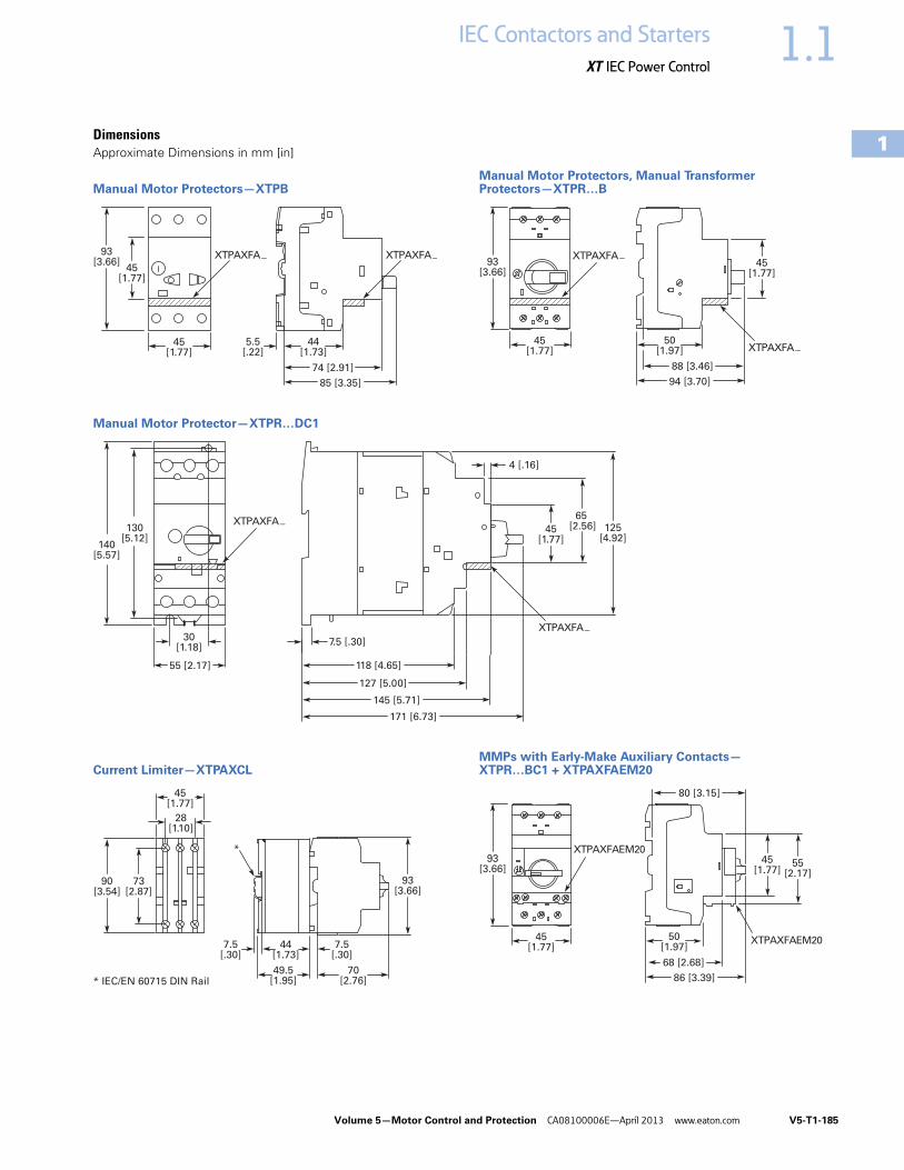
DimensionsApproximate Dimensions in mm [in]
Manual Motor Protectors—XTPBManual Motor Protectors, Manual Transformer Protectors—XTPR…B
Manual Motor Protector—XTPR…DC1
Current Limiter—XTPAXCLMMPs with Early-Make Auxiliary Contacts—XTPR…BC1 + XTPAXFAEM20
5.5[.22]
45[1.77]
45[1.77]
93[3.66]
44[1.73]
74 [2.91]
85 [3.35]
XTPAXFA_ XTPAXFA_
45[1.77]
93[3.66]
45[1.77]
50[1.97]
88 [3.46]
94 [3.70]
XTPAXFA_
XTPAXFA_
30[1.18]
7.5 [.30]
118 [4.65]
127 [5.00]
145 [5.71]
171 [6.73]
55 [2.17]
130[5.12]
140[5.57]
125[4.92]
65 [2.56]45
[1.77]
4 [.16]
XTPAXFA_
XTPAXFA_
*
93[3.66]
28[1.10]
45[1.77]
* IEC/EN 60715 DIN Rail
90[3.54]
73[2.87]
7.5[.30]
7.5[.30]
44[1.73]
70[2.76]
49.5[1.95]
XTPAXFAEM20
XTPAXFAEM20
45[1.77]
45[1.77]
55[2.17]
93[3.66]
50[1.97]
68 [2.68]
86 [3.39]
80 [3.15]

V5-T1-186 Volume 5—Motor Control and Protection CA08100006E—April 2013 www.eaton.com
1
1
1
1
1
1
1
1
1
1
1
1
1
1
1
1
1
1
1
1
1
1
1
1
1
1
1
1
1
1
1.1 IEC Contactors and Starters
XT IEC Power Control
Approximate Dimensions in mm [in]
Standard Auxiliary Contact—XTPAXSA_
Trip Indicating Auxiliary Contact—XTPAXSATR_
Undervoltage/Shunt Release—XTPAXUVR_, XTPAXSR_
Three-Phase Commoning Link—XTPAXCLKA4, XTPAXCLKA2
Three-Phase Commoning Link—XTPAXCLKB5, XTPAXCLKB4, XTPAXCLKB3 and XTPAXCLKB2
Three-Phase Commoning Link—XTPAXCLKC4, XTPAXCLKC2
Incoming Terminal, Line Side Adapter—XTPAXIT, XTPAXLSA
45[1.77]
36[1.42]
90[3.54]
26[1.02]
68 [2.68]
9[.35]
36[1.42]
45[1.77]
90[3.54]
26[1.02]
68 [2.68]
9[.35]
36[1.42]
45[1.77]
90[3.54]
18[.71]
49[1.93]
68 [2.68]
180 [7.09] (90 [3.54])
27[1.06]
45[1.77]
Overlapping Mountingto Extend the Three-PhaseCommoning Link
261 [10.28] (207 [8.15],153 [6.02], 99 [3.90])
27[1.06]
54[2.13]
234 [9.21] (108 [4.25])
27[1.06]
63[2.48]
XTPAXLSA73
[2.87] 48[1.89]
XTPAXIT
31[1.22]
7.5[.30]
41[1.61]
56[2.20]

Volume 5—Motor Control and Protection CA08100006E—April 2013 www.eaton.com V5-T1-187
1
1
1
1
1
1
1
1
1
1
1
1
1
1
1
1
1
1
1
1
1
1
1
1
1
1
1
1
1
1
1.1IEC Contactors and Starters
XT IEC Power Control
Approximate Dimensions in mm [in]
Three-Phase Commoning Link
XTPAXCLKA4D, XTPAXCLKA3D and XTPAXCLKA2D
XTPAXCLKA4D
XTPAXCLKA3D
XTPAXCLKA2D
XTPAXCLKB4D, XTPAXCLKB3D and XTPAXCLKB2D
XTPAXCLKB4D
XTPAXCLKB3D
XTPAXCLKB2D
XTPAXCLKC4D and XTPAXCLKC2D
XTPAXCLKC4D
XTPAXCLKC2D
14[.55]
205 [8.07] 33[1.30]
36[1.42]
151 [5.94] 14[.55]
36[1.42]
33[1.30]
98 [3.86] 14[.55]
36[1.42]
33[1.30]
232 [9.13] 14[.55]
36[1.42]
33[1.30]
170 [6.69] 14[.55]
36[1.42]
33[1.30]
117 [4.6] 14[.55]
36[1.42]
33[1.30]
260 [10.24] 14[.55]
36[1.42]
33[1.30]
115 [4.53] 14[.55]
36[1.42]
33[1.30]

V5-T1-188 Volume 5—Motor Control and Protection CA08100006E—April 2013 www.eaton.com
1
1
1
1
1
1
1
1
1
1
1
1
1
1
1
1
1
1
1
1
1
1
1
1
1
1
1
1
1
1
1.1 IEC Contactors and Starters
XT IEC Power Control
Approximate Dimensions in mm [in]
Insulated Enclosures for Surface Mounting of XTPB Manual Motor Protectors
Insulated Enclosures for Flush Mounting of XTPB Manual Motor Protectors
158[6.22]
80 [3.15] 116.5 [4.59]
158[6.22]
80 [3.15] 116.5 [4.59]
177.2 [6.98]
158[6.22]
80 [3.15] 116.5 [4.59]
129.5 [5.10]
XTPBXENCS40, XTPBXENCS65, XTPBXENAS41, XTPBXENAS65 XTPBXENCSEK65, XTPBXENCSES65, XTPBXENASEK65, XTPBXENASES65
XTPBXENCSLE65, XTPBXENCSLO65, XTPBXENASLE65, XTPBXENASO065
129[5.08]
90.2[3.55]
69[2.72]
93 [3.66]
115.2 [4.54]
129[5.08]
90.2[3.55]
69[2.72]
93 [3.66]
115.2 [4.54]
175.9 [6.93]
129[5.08]
90.2[3.55]
69[2.72]
93 [3.66]
115.2 [4.54]
XTPBXENCF40, XTPBXENCF55 XTPBXENCFEK55, XTPBXENCFES55
XTPBXENCFLE55, XTPBXENCFLO55

Volume 5—Motor Control and Protection CA08100006E—April 2013 www.eaton.com V5-T1-189
1
1
1
1
1
1
1
1
1
1
1
1
1
1
1
1
1
1
1
1
1
1
1
1
1
1
1
1
1
1
1.1IEC Contactors and Starters
XT IEC Power Control
Approximate Dimensions in mm [in]
Insulated Enclosures for Surface Mounting of XTPR…B Manual Motor Protectors
158[6.22]
70[2.76]
80 [3.15] 90 [3.54]
100 [3.94]
44[1.73]
55[2.17]
98 [3.86]
SVB-PKZ0-CI
30 [1.18]
33[1.30]
80 [3.15]
158[6.22]
97.5 [3.84] 28[1.10]
30[1.18]
4.5[.18]
4.5[.18] 8
[.31]
153[6.02]
Drilling Dimensions
160[6.30]
181[7.13]
100[3.94]
47.5[1.87]
104[4.09]
33[1.30]
55[2.17]
SVB-PKZ0-CI
97 [3.82]
160[6.30]
181[7.13]
44[1.73]
98 [3.86]
30 [1.18]
114 [4.49] 28[1.10]
30[1.18]
M4
M4
171[6.73]
Drilling Dimensions
XTPAXENCS40
158[6.22]
80 [3.15] 97.5 [3.84]
125.5 [4.94]
4.5 [.18]
4.5[.18]
8 [.31]
153[6.02]
Drilling Dimensions
160[6.30]
181[7.13]
100[3.94]
47.5[1.87]
103 [4.06]
130 [5.12]
M4
M4
171[6.73]
Drilling Dimensions
XTPAXENCS65B, XTPAXENCS65RY, XTPAXENCSEM65B, XTPAXENCSEM65RY, XTPAXENAS55B, XTPAXENAS55RY, XTPAXENASEM55B, XTPAXENASEM55RY, XTPAXENCSH65B, XTPAXENCSH65RY, XTPAXENCSEMH65B, XTPAXENCSEMH65RY
XTPAXENCS55B, XTPAXENCS55RY, XTPAXENCSEM55B, XTPAXENCSEM55RY
XTPAXENCS55_ + XTPAXPL1, XTPAXENCSEM55_ + XTPAXPL1
XTPAXENCSH41, XTPAXENCS41, XTPAXENAS41
XTPAXENCS65_ + XTPAXPL1, XTPAXENCSEM65_ + XTPAXPL1

V5-T1-190 Volume 5—Motor Control and Protection CA08100006E—April 2013 www.eaton.com
1
1
1
1
1
1
1
1
1
1
1
1
1
1
1
1
1
1
1
1
1
1
1
1
1
1
1
1
1
1
1.1 IEC Contactors and Starters
XT IEC Power Control
Approximate Dimensions in mm [in]
Insulated Enclosures for Flush Mounting of XTPR…B Manual Motor Protectors
69[2.72]
85 [3.35]
129[5.08]
96 [3.78]
80 [3.15]
124 [4.88]
55[2.17]
4 [.16]R
70 – 72[2.76 – 2.83]
116 – 118[4.57 – 4.64]
98[3.86]
30[1.18]
58[2.28]
55[2.17]
96 [3.78]
80 [3.15]
124 [4.88]
XTPAXENCF40, XTPAXENCF55B, XTPAXENCF55RY Mounting Cutout XTPAXENCF_
XTPAXENCF55_ + XTPAXPL3
85[3.35]
129[5.08]
30[1.18]
28 [1.10]
21[.83]

Volume 5—Motor Control and Protection CA08100006E—April 2013 www.eaton.com V5-T1-191
1
1
1
1
1
1
1
1
1
1
1
1
1
1
1
1
1
1
1
1
1
1
1
1
1
1
1
1
1
1
1.1IEC Contactors and Starters
XT IEC Power Control
Approximate Dimensions in mm [in]
Insulated Enclosures for Surface Mounting of XTPR…D Manual Motor Protectors
Rotary Handle Mechanism—XTPAXRHM_
160 [6.30]
240[9.45]
134 [5.28]
181 [7.13]
197 [7.76]
32 [1.26]
SVB-PKZ4-CI
98 [3.86]
72[2.83]
3 [.12]
160 [6.30] 186 [7.32] 28 [1.10]
30[1.18]
193[7.60]
142 [5.60]
5.6 [.22]Dia.
72[2.83]
240[9.45]
Drilling Dimensions
XTPAXENCSD65_ + XTPAXPL2XTPAXENCSD65B, XTPAXENCSD65RY
XTPAXENCSD65
48[1.89]
At least 100 [3.94]up to Cover Hinge
Mounting Depth:100 – 240 [3.94 – 9.45]from the top edge ofthe mounting rail to thefront edge of the paneldoor/cover
48[1.89]
43 [1.69] Dia.
64[2.52]
64[2.52]
19.5[.77]
62[2.44]

V5-T1-192 Volume 5—Motor Control and Protection CA08100006E—April 2013 www.eaton.com
1
1
1
1
1
1
1
1
1
1
1
1
1
1
1
1
1
1
1
1
1
1
1
1
1
1
1
1
1
1
1.1 IEC Contactors and Starters
XT IEC Power Control
Approximate Dimensions in mm [in]
Pushbutton MMP Enclosures
Insulated Enclosures for Surface Mounting
XTPB Pushbutton Motor-Protective Circuit Breakers
XTPB Pushbutton Manual Motor Protectors
Frame B (0.1–32A) XTPR Motor-Protective Circuit Breakers
Frame B (0.1–32A) XTPR Rotary Manual Motor Protectors
Frame B XTPR (0.1–32A) Rotary Motor-Protective Circuit Breakers with XTPAXFAEM20 Early-Make Front-Mount Auxiliary Contact
Frame B XTPR (0.1–32A) Rotary Manual Motor Protectors with XTPAXFAEM20 Early-Make Front-Mount Auxiliary Contact
Frame D (10–65A) Rotary Motor-Protective Circuit Breakers
Insulated Enclosures for Flush Mounting
XTPB Pushbutton Manual Motor Protectors
Frame B (0.1–32A) XTPR Rotary Manual Motor Protectors
Catalog Number H x W x D
Global Usage
XTPBXENCS40 158 x 80 x 116.5[6.22 x 3.15 x 4.59]
XTPBXENCS65 158 x 80 x 116.5[6.22 x 3.15 x 4.59]
XTPBXENCSLO65 158 x 80 x 129.5[6.22 x 3.15 x 5.10]
XTPBXENCSLE65 158 x 80 x 129.5[6.22 x 3.15 x 5.10]
XTPBXENCSES65 158 x 80 x 177.2[6.22 x 3.15 x 6.98]
XTPBXENCSEK65 158 x 80 x 177.2[6.22 x 3.15 x 6.98]
Catalog Number H x W x D
North American Usage
XTPBXENAS41 158 x 80 x 116.5[6.22 x 3.15 x 4.59]
XTPBXENAS65 158 x 80 x 116.5[6.22 x 3.15 x 4.59]
XTPBXENASLO65 158 x 80 x 129.5[6.22 x 3.15 x 5.10]
XTPBXENASLE65 158 x 80 x 129.5[6.22 x 3.15 x 5.10]
XTPBXENASES65 158 x 80 x 177.2[6.22 x 3.15 x 6.98]
XTPBXENASEK65 158 x 80 x 177.2[6.22 x 3.15 x 6.98]
Catalog Number H x W x D
Global Usage
XTPAXENCS41 160 x 100 x 104[6.30 x 3.94 x 4.09]
XTPAXENCS65B 160 x 100 x 130[6.30 x 3.94 x 5.12]
XTPAXENCS65RY 160 x 100 x 130[6.30 x 3.94 x 5.12]
XTPAXENCS40 158 x 80 x 100[6.22 x 3.15 x 3.94]
XTPAXENCS55B 158 x 80 x 125.5[6.22 x 3.15 x 4.94]
XTPAXENCS55RY 158 x 80 x 125.5[6.22 x 3.15 x 4.94]
Catalog Number H x W x D
North American Usage
XTPAXENAS55B 160 x 100 x 130[6.30 x 3.94 x 5.12]
XTPAXENAS55RY 160 x 100 x 130[6.30 x 3.94 x 5.12]
Catalog Number H x W x D
Global Usage
XTPAXENCSEM65B 160 x 100 x 130[6.30 x 3.94 x 5.12]
XTPAXENCSEM65RY 160 x 100 x 130[6.30 x 3.94 x 5.12]
XTPAXENCSEM55B 158 x 80 x 100[6.22 x 3.15 x 3.94]
XTPAXENCSEM55RY 158 x 80 x 100[6.22 x 3.15 x 3.94]
Catalog Number H x W x D
North American Usage
XTPAXENCSEM55B 160 x 100 x 130[6.30 x 3.94 x 5.12]
XTPAXENCSEM55RY 160 x 100 x 130[6.30 x 3.94 x 5.12]
Catalog Number H x W x D
Global and North American Usage
XTPAXENCSD65B 240 x 160 x 197[9.45 x 6.30 x 7.76]
XTPAXENCSD65RY 240 x 160 x 197[9.45 x 6.30 x 7.76]
Catalog Number H x W x D
Global and North American Usage
XTPBXENCF40 129 x 90.2 x 115.2[5.08 x 3.55 x 4.54]
XTPBXENCF55 129 x 90.2 x 115.2[5.08 x 3.55 x 4.54]
XTPBXENCFLO55 129 x 90.2 x 115.2[5.08 x 3.55 x 4.54]
XTPBXENCFLE55 129 x 90.2 x 115.2[5.08 x 3.55 x 4.54]
XTPBXENCFES55 129 x 90.2 x 175.9[5.08 x 3.55 x 6.93]
XTPBXENCFEK55 129 x 90.2 x 175.9[5.08 x 3.55 x 6.93]
Catalog Number H x W x D
Global Usage
XTPAXENCF40 129 x 85 x 96[5.08 x 3.35 x 3.78]
XTPAXENCF55B 129 x 85 x 124[5.08 x 3.35 x 4.88]
XTPAXENCF55RY 129 x 85 x 124[5.08 x 3.35 x 4.88]

Volume 5—Motor Control and Protection CA08100006E—April 2013 www.eaton.com V5-T1-193
1
1
1
1
1
1
1
1
1
1
1
1
1
1
1
1
1
1
1
1
1
1
1
1
1
1
1
1
1
1
1.1IEC Contactors and Starters
XT IEC Power Control
Combination Motor Controllers ContentsDescription Page
Relays and Timers . . . . . . . . . . . . . . . . . . . . . . . . . V5-T1-3Miniature Controls . . . . . . . . . . . . . . . . . . . . . . . . . V5-T1-18Contactors and Starters . . . . . . . . . . . . . . . . . . . . V5-T1-35Thermal Overload Relays . . . . . . . . . . . . . . . . . . . . V5-T1-128C440/XT Electronic Overload Relay . . . . . . . . . . . V5-T1-141Manual Motor Protectors . . . . . . . . . . . . . . . . . . . V5-T1-157Combination Motor Controllers
Features . . . . . . . . . . . . . . . . . . . . . . . . . . . . . . V5-T1-194Standards and Certifications . . . . . . . . . . . . . . V5-T1-194Catalog Number Selection . . . . . . . . . . . . . . . . V5-T1-195Product Selection . . . . . . . . . . . . . . . . . . . . . . . V5-T1-195Accessories . . . . . . . . . . . . . . . . . . . . . . . . . . . V5-T1-203Technical Data and Specifications . . . . . . . . . . V5-T1-205Dimensions . . . . . . . . . . . . . . . . . . . . . . . . . . . V5-T1-211
An EatonGreen Solution
XT Electronic Manual Motor Protector . . . . . . . . . V5-T1-216Reference Data . . . . . . . . . . . . . . . . . . . . . . . . . . . V5-T1-229
Combination Motor ControllersProduct DescriptionEaton’s XT IEC open non-reversing and reversing manual motor controllers combine a manual motor protector with an IEC contactor(s) to provide a complete motor protection solution by combining motor disconnect function, thermal overload protection, magnetic short-circuit protection and remote control operation in one compact, assembled unit. these assembled manual motor controllers cover motors with FLA ratings from 0.10A to 65A.
The UL 508 Type F labeled combination motor controller (CMC) includes a line side adapter (LSA). These assembled combination motor controllers cover motors with FLA ratings from 0.10A to 65A.
Application DescriptionThe XT IEC non-reversing and reversing manual and combination motor controllers can be used in the following applications:
Group Motor ControlManual motor controllers (MMCs) are ideal for group motor applications where an upstream breaker or fuse provides protection for two or more motors. XT manual motor controllers (MMC) combine a manual motor protector, a wiring connector link and IEC contactor.
Individual Branch Circuit for Motor LoadsCombination motor controller (CMC), consisting of a line side adapter, manual motor protector, wiring connector link and IEC contactor, provide an efficient means to build an entire branch circuit. The XT CMC is UL 508 Type F approved, meaning it is “self-protected” and doesn’t require the use of an additional fuse or breaker for short circuit protection. This approval means CMC’s can be used in place of a traditional fuse-starter and breaker-starter motor circuit.
Based around two key functional components (MMP and contactor), the CMC is a very cost effective means to build a branch circuit. Fuses and breakers must be oversized to prevent tripping during motor start up, and thus these oversized devices can no longer protect the motor. To compensate for this, a motor overload relay is necessary to protect the motor.
The manual motor protector was invented in Germany by Moeller to correct this inefficiency. The MMP operates similarly to a circuit breaker, except the inrush (magnetic) protection is set to 14 times the running current, thus accounting for motor start-up current without the necessity to oversize. A overcurrent dial was added to the face of the MMP to serve as the motor overload protection. This “motor protective circuit breaker”, as it is referred to in Europe, now accomplishes all four key functions of a motor branch circuit: disconnect, short circuit, motor controller and motor overload protection. With the addition of a contactor, users have the ability to remotely control the starter device.
Whether a single motor application or a multiple motor application, CMC’s are an ideal solution for machinery OEMs and panel builders.

V5-T1-194 Volume 5—Motor Control and Protection CA08100006E—April 2013 www.eaton.com
1
1
1
1
1
1
1
1
1
1
1
1
1
1
1
1
1
1
1
1
1
1
1
1
1
1
1
1
1
1
1.1 IEC Contactors and Starters
XT IEC Power Control
Features● ON/OFF rotary handle
with lockout provision● Visible trip indication● Test trip function● Motor applications
from 0.10A to 65A● Class 10 overload
protection● Built-in heater and
magnetic trip elements to protect the motor
● Phase loss sensitivity● Type 2 coordination● Ambient compensated
up to 55°C [140°F]● Control inputs located at
front of starter for easy access and wiring
● Wide range of coils● DIN rail mount—
XTSC…BB_● Mounting plates—
XTSC…BC_, XTSC…D motor controllers
● Adjustment dial for setting motor FLA
● Short-circuit trip at 14 times the maximum setting of the FLA adjustment dial
● UL 508 Type F CMC high fault short-circuit ratings
● 1NO-1NC auxiliary contact as standard on manual motor controller and combination motor controller
Standards and CertificationsUL 508 Type F combination motor controller
● IEC Type 2 Approved per IEC 60947-4-1
● UL Listed File No. E245398● CE Mark
Note: For Type 2 Coordination of MMCs, see Page V5-T1-230. Protection in different controller types
MMC and CMC Applications
Notes
Technical Paper AP03402001E.Line side adapters are not required for non-U.S. applications. Most countries outside of the U.S. classify the MMP as a motor-protective circuit breaker.1 SCPD = Short-circuit protective device (circuit breaker, fuses).2 MMC = Manual motor controller
Combination Motor ControllerXTFC/XTFR
Line Side Adapter (LSA)Not required
Line Side Adapter (LSA)Required—factory assembled
XTIEC Manual and Combination Motor Controllers
Manual Motor ControllerUse in group installation applications. Upstream SCPD 1 is required and must be sized smaller than the maximum upstream SCPD 1 rating on each MMC 2 used. Tap rules should also be observed.
UL 508 Type F CombinationMotor Controller
Use for single motor branch circuits or use multiple CMC’s for a multiple motor panel applications. No additional SCPD 1 is required in the branch, as these devices are “self-protected”.
Manual Motor ControllerXTSC/XTSR

Volume 5—Motor Control and Protection CA08100006E—April 2013 www.eaton.com V5-T1-195
1
1
1
1
1
1
1
1
1
1
1
1
1
1
1
1
1
1
1
1
1
1
1
1
1
1
1
1
1
1
1.1IEC Contactors and Starters
XT IEC Power Control
Catalog Number Selection
Combination Motor Controllers
Product Selection
XTSC and XTSR Manual Motor Controllers (MMC)/Starter Combinations
Factory-Assembled Manual Motor Controller—Frame B MMP + Frame B Contactor—Maximum UL Ratings 1
Notes1 Select manual motor controllers by full load amperes. Maximum motor ratings (kW, hp) are for reference only.2 Underscore (_) indicates magnetic coil suffix required. See Page V5-T1-198.3 In this range, calculate motor rating according to rated current. Specified values to NEC 430.6(A)(1).
FLA AdjustmentRange/OverloadRelease—Ir (Amps)
Short-CircuitRelease—Irm (Amps)
Assembled Manual Motor Controller 2Three-Phase
200V 240V 480V 600VNon-ReversingCatalog Number
ReversingCatalog Number
0.1–0.16 3.2 3 3 1/2 1/2 XTSCP16BB_ XTSRP16BB_
0.16–0.25 3.5 3 3 1/2 1/2 XTSCP25BB_ XTSRP25BB_
0.25–0.4 5.6 3 3 1/2 1/2 XTSCP40BB_ XTSRP40BB_
0.4–0.63 8.82 3 3 1/2 1/2 XTSCP63BB_ XTSRP63BB_
0.63–1 14 3 3 1/2 1/2 XTSC001BB_ XTSR001BB_
1–1.6 22.4 3 3 3/4 1 XTSC1P6BB_ XTSR1P6BB_
1.6–2.5 35 1/2 1/2 1 1-1/2 XTSC2P5BB_ XTSR2P5BB_
2.5–4 56 1 1 2 3 XTSC004BB_ XTSR004BB_
4–6.3 88.2 1-1/2 1-1/2 3 5 XTSC6P3BB_ XTSR6P3BB_
6.3–10 140 3 3 7-1/2 3 XTSC010BB_ XTSR010BB_
8–12 168 3 3 7-1/2 3 XTSC012BB_ XTSR012BB_
10–16 224 3 3 10 3 XTSC016BB_ —
XT SC 012 B B A
TypeSC = Manual motor controller—
FVNRSR = Manual motor controller—
FVRFC = Combination motor controller,
UL 508 Type F—FVNRFR = Combination motor controller,
UL 508 Type F—FVR
DesignationXT = XT IEC power control
Coil VoltageA = 110V 50 Hz, 120V 60 HzB = 220V 50 Hz, 240V 60 HzC = 415V 50 Hz, 480V 60 HzD = 600V 60 HzE = 208V 50 HzF = 230V 50 HzG = 190V 50 Hz, 220V 60 HzH = 240V 50 Hz, 277V 60 HzL = 380V 50 Hz, 440V 60 HzN = 400V 50 HzP = 380V 60 HzR = 12V 50/60 HzT = 24V 50/60 HzW = 42V 50 Hz, 48V 60 HzY = 48V 50 HzAD = 120 VdcBD = 220 VdcRD = 12 VdcTD = 24 VdcWD = 48 Vdc
Frame Size—ContactorB = 45 mm, 7 to 15AC = 45 mm, 18 to 32AD = 55 mm, 40 to 65A
Rated Current of MMPFrame BP16 = 0.16AP25 = 0.25AP40 = 0.40AP63 = 0.63A001 = 1A1P6 = 1.6A2P5 = 2.5A004 = 4A6P3 = 6.3A010 = 10A012 = 12A016 = 16A020 = 20A025 = 25A032 = 32A
Frame D016 = 16A025 = 25A032 = 32A040 = 40A050 = 50A058 = 58A063 = 63A
Frame Size—MMPB = 45 mm, 0.1 to 32AD = 55 mm, 16 to 63A
Frame B MMP +Frame B Contactor

V5-T1-196 Volume 5—Motor Control and Protection CA08100006E—April 2013 www.eaton.com
1
1
1
1
1
1
1
1
1
1
1
1
1
1
1
1
1
1
1
1
1
1
1
1
1
1
1
1
1
1
1.1 IEC Contactors and Starters
XT IEC Power Control
Factory-Assembled Motor Protective Device with Thermal and Magnetic Trip + Contactor—Maximum IEC Ratings1
Factory-Assembled Manual Motor Controller—Frame B MMP + Frame C Contactor—Maximum UL Ratings 1
Factory-Assembled Manual Motor Controller—Frame B MMP + Frame C Contactor—Maximum IEC RatingS 1
Notes1 Select manual motor controllers by full load amperes. Maximum motor ratings (kW, hp) are for reference only.2 Underscore (_) indicates magnetic coil suffix required. See Page V5-T1-198.
FLA AdjustmentRange/OverloadRelease—Ir (Amps)
Short-CircuitRelease—Irm (Amps)
Three-Phase Assembled Manual Motor Controller 2
220–240V
380–415V 500V
660–690V
Non-ReversingCatalog Number
ReversingCatalog Number
0.1–0.16 3.2 — — — 0.06 XTSCP16BB_ XTSRP16BB_
0.16–0.25 3.5 — 0.06 0.06 0.12 XTSCP25BB_ XTSRP25BB_
0.25–0.4 5.6 0.06 0.09 0.12 0.18 XTSCP40BB_ XTSRP40BB_
0.4–0.63 8.82 0.09 0.18 0.25 0.25 XTSCP63BB_ XTSRP63BB_
0.63–1 14 0.12 0.25 0.37 0.55 XTSC001BB_ XTSR001BB_
1–1.6 22.4 0.25 0.55 0.75 1.1 XTSC1P6BB_ XTSR1P6BB_
1.6–2.5 35 0.37 0.75 1.1 1.5 XTSC2P5BB_ XTSR2P5BB_
2.5–4 56 0.75 1.5 2.2 3 XTSC004BB_ XTSR004BB_
4–6.3 88.2 1.1 2.2 3 4 XTSC6P3BB_ XTSR6P3BB_
6.3–10 140 2.2 4 4 7.5 XTSC010BB_ XTSR010BB_
8–12 168 3 5.5 5.5 11 XTSC012BB_ XTSR012BB_
10–16 224 4 7.5 9 12.5 XTSC016BB_ —
FLA AdjustmentRange/OverloadRelease—Ir (Amps)
Short-CircuitRelease—Irm (Amps)
Assembled Manual Motor Controller 2
Three-Phase Non-ReversingCatalog Number
ReversingCatalog Number200V 240V 480V 600V
10–16 224 3 3 10 10 XTSC016BC_ XTSR016BC_
16–20 280 5 5 10 15 XTSC020BC_ XTSR020BC_
20–25 350 5 7-1/2 15 20 XTSC025BC_ XTSR025BC_
25–32 448 7-1/2 10 20 25 XTSC032BC_ XTSR032BC_
FLA AdjustmentRange/OverloadRelease—Ir (Amps)
Short-CircuitRelease—Irm (Amps)
Three-Phase Assembled Manual Motor Controller 2
220–240V
380–415V 500V
660–690V
Non-ReversingCatalog Number
ReversingCatalog Number
10–16 224 4 7.5 9 12.5 XTSC016BC_ XTSR016BC_
16–20 280 5.5 9 12.5 15 XTSC020BC_ XTSR020BC_
20–25 350 5.5 11 15 22 XTSC025BC_ XTSR025BC_
25–32 448 7.5 15 22 30 XTSC032BC_ XTSR032BC_
Frame B MMP +Frame B Contactor
Frame B MMP +Frame C Contactor
Frame B MMP +Frame C Contactor
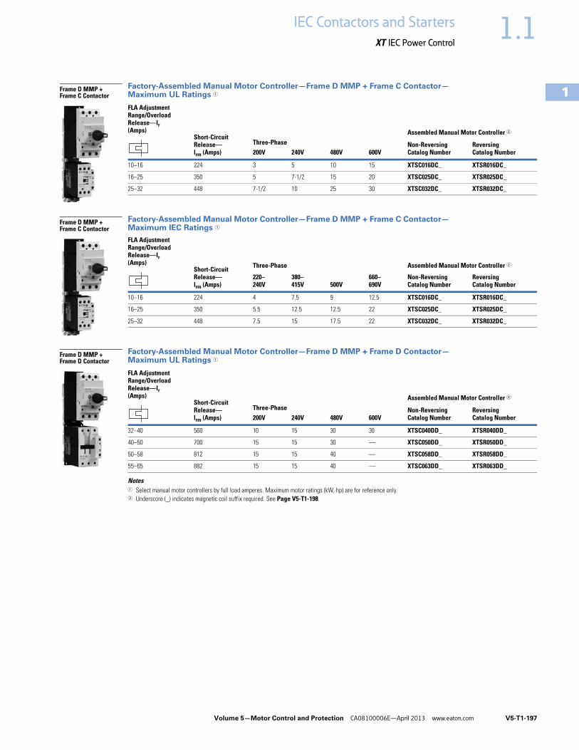
Volume 5—Motor Control and Protection CA08100006E—April 2013 www.eaton.com V5-T1-197
1
1
1
1
1
1
1
1
1
1
1
1
1
1
1
1
1
1
1
1
1
1
1
1
1
1
1
1
1
1
1.1IEC Contactors and Starters
XT IEC Power Control
Factory-Assembled Manual Motor Controller—Frame D MMP + Frame C Contactor—Maximum UL Ratings 1
Factory-Assembled Manual Motor Controller—Frame D MMP + Frame C Contactor—Maximum IEC Ratings 1
Factory-Assembled Manual Motor Controller—Frame D MMP + Frame D Contactor—Maximum UL Ratings 1
Notes1 Select manual motor controllers by full load amperes. Maximum motor ratings (kW, hp) are for reference only.2 Underscore (_) indicates magnetic coil suffix required. See Page V5-T1-198.
FLA AdjustmentRange/OverloadRelease—Ir (Amps)
Short-CircuitRelease—Irm (Amps)
Assembled Manual Motor Controller 2
Three-Phase Non-ReversingCatalog Number
ReversingCatalog Number200V 240V 480V 600V
10–16 224 3 5 10 15 XTSC016DC_ XTSR016DC_
16–25 350 5 7-1/2 15 20 XTSC025DC_ XTSR025DC_
25–32 448 7-1/2 10 25 30 XTSC032DC_ XTSR032DC_
FLA AdjustmentRange/OverloadRelease—Ir (Amps)
Short-CircuitRelease—Irm (Amps)
Three-Phase Assembled Manual Motor Controller 2
220–240V
380–415V 500V
660–690V
Non-ReversingCatalog Number
ReversingCatalog Number
10–16 224 4 7.5 9 12.5 XTSC016DC_ XTSR016DC_
16–25 350 5.5 12.5 12.5 22 XTSC025DC_ XTSR025DC_
25–32 448 7.5 15 17.5 22 XTSC032DC_ XTSR032DC_
FLA AdjustmentRange/OverloadRelease—Ir (Amps)
Short-CircuitRelease—Irm (Amps)
Assembled Manual Motor Controller 2
Three-Phase Non-ReversingCatalog Number
ReversingCatalog Number200V 240V 480V 600V
32–40 560 10 15 30 30 XTSC040DD_ XTSR040DD_
40–50 700 15 15 30 — XTSC050DD_ XTSR050DD_
50–58 812 15 15 40 — XTSC058DD_ XTSR058DD_
55–65 882 15 15 40 — XTSC063DD_ XTSR063DD_
Frame D MMP +Frame C Contactor
Frame D MMP +Frame C Contactor
Frame D MMP +Frame D Contactor

V5-T1-198 Volume 5—Motor Control and Protection CA08100006E—April 2013 www.eaton.com
1
1
1
1
1
1
1
1
1
1
1
1
1
1
1
1
1
1
1
1
1
1
1
1
1
1
1
1
1
1
1.1 IEC Contactors and Starters
XT IEC Power Control
Factory-Assembled Manual Motor Controller—Frame D MMP + Frame D Contactor—Maximum IEC Ratings 1
AC and DC Coil Suffixes
NotesThe assembled manual motor controller (MMC) consists of an XTPR manual motor protector (MMP) and an XTCE contactor. For Frame B MMP + Frame B contactor assemblies, the XTSC and XTSR can be mounted directly on DIN rail without an adapter. The contactors are supported mechanically with a mechanical connection element (included in XTPAXTPCB, XTPAXRPCRB). For MMCs using a Frame C or Frame D contactor, the assembly is mounted via a DIN rail adapter plate (XTPAXTPCPC, XTPAXTPCPD) and the electrical connection is made with electrical contact modules (XTPAXECMC, XTPAXECMD), both included in XTPAXTPCC and XTPAXTPCD.
Service Factor (SF)—Setting Ir of current scale in dependence of load factor:SF = 1.15 → Ir = 1 x In mot SF = 1 → Ir = 0.9 x In mot
Single-phasing sensitivity to IEC/EN 60947-4-1, VDE 0660 Part 102.1 Select manual motor controllers by full load amperes. Maximum motor ratings (kW, hp) are for reference only.2 Underscore (_) indicates magnetic coil suffix required. See AC and DC coil suffixes above. 3 With DC operation: Integrated diode-resistor combination, coil rating 2.6W.
Non-Reversing Manual Motor Controller Power Circuit
Reversing Manual Motor Controller Power Circuit
FLA AdjustmentRange/OverloadRelease—Ir (Amps)
Short-CircuitRelease—Irm (Amps)
Three-Phase Assembled Manual Motor Controller 2
220–240V
380–415V 500V
660–690V
Non-ReversingCatalog Number
ReversingCatalog Number
32–40 560 11 20 22 30 XTSC040DD_ XTSR040DD_
40–50 700 14 25 30 45 XTSC050DD_ XTSR050DD_
50–58 812 17 30 37 55 XTSC058DD_ XTSR058DD_
55–65 882 18.5 34 37 55 XTSC063DD_ XTSR063DD_
Frame D MMP +Frame D Contactor
Coil Voltage Suffix Code
Frame B Contactors
110V 50 Hz, 120V 60 Hz A
220V 50 Hz, 240V 60 Hz B
230V 50 Hz F
24V 50/60 Hz T
24 Vdc TD 3
415V 50 Hz, 480V 60 Hz C
600V 60 Hz D
208V 60 Hz E
190V 50 Hz, 220V 60 Hz G
240V 50 Hz, 277V 60 Hz H
Coil Voltage Suffix Code
380V 50 Hz, 440V 60 Hz L
400V 50 Hz N
380V 60 Hz P
12V 50/60 Hz R
42V 50 Hz, 48V 60 Hz W
48V 50 Hz Y
120 Vdc AD 3
220 Vdc BD 3
12 Vdc RD 3
48 Vdc WD 3
Coil Voltage Suffix Code
Frame C and D Contactors
110V 50 Hz, 120V 60 Hz A
220V 50 Hz, 240V 60 Hz B
230V 50 Hz F
24V 50/60 Hz T
24–27 Vdc TD 3
415V 50 Hz, 480V 60 Hz C
550V 50 Hz, 600V 60 Hz D
208V 60 Hz E
190V 50 Hz, 220V 60 Hz G
240V 50 Hz, 277V 60 Hz H
Coil Voltage Suffix Code
380V 50 Hz, 440V 60 Hz L
400V 50 Hz N
380V 60 Hz P
12V 50/60 Hz R
42V 50 Hz, 48V 60 Hz W
48V 50 Hz Y
110–130 Vdc AD 3
200–240 Vdc BD 3
12–14 Vdc RD 3
48–60 Vdc WD 3
M3 ~
M3 ~

Volume 5—Motor Control and Protection CA08100006E—April 2013 www.eaton.com V5-T1-199
1
1
1
1
1
1
1
1
1
1
1
1
1
1
1
1
1
1
1
1
1
1
1
1
1
1
1
1
1
1
1.1IEC Contactors and Starters
XT IEC Power Control
XTFC and XTFR Combination Motor Controllers (CMC), UL 508 Type F
Factory-Assembled Type F Combination Motor Controller—Frame B MMP + Frame B Contactor—Maximum UL Ratings 1
Factory-Assembled Type F Combination Motor Controller—Frame B MMP + Frame B Contactor—Maximum IEC Ratings 1
Notes1 Select combination motor controllers by full load amperes. Maximum motor ratings (kW, hp) are for reference only.2 Underscore (_) indicates magnetic coil suffix required. See Page V5-T1-202.3 In this range, calculate motor rating according to rated current. Specified values to NEC 430.6(A)(1).
FLA AdjustmentRange/OverloadRelease—Ir (Amps)
Short-CircuitRelease—Irm (Amps)
Assembled Manual Motor Controller 2
Three-Phase Non-ReversingCatalog Number
ReversingCatalog Number200V 240V 480V 600V
0.16–0.25 3.5 3 3 1/2 1/2 XTFCP25BB_ XTFRP25BB_
0.25–0.4 5.6 3 3 1/2 1/2 XTFCP40BB_ XTFRP40BB_
0.4–0.63 8.82 3 3 1/2 1/2 XTFCP63BB_ XTFRP63BB_
0.63–1 14 3 3 1/2 1/2 XTFC001BB_ XTFR001BB_
1–1.6 22.4 3 3 3/4 1 XTFC1P6BB_ XTFR1P6BB_
1.6–2.5 35 1/2 1/2 1 1-1/2 XTFC2P5BB_ XTFR2P5BB_
2.5–4 56 1 1 2 3 XTFC004BB_ XTFR004BB_
4–6.3 88.2 1-1/2 1-1/2 3 5 XTFC6P3BB_ XTFR6P3BB_
6.3–10 140 3 3 7-1/2 10 XTFC010BB_ XTFR010BB_
8–12 168 3 3 7-1/2 — XTFC012BB_ XTFR012BB_
10–16 224 3 5 10 — XTFC016BB_ —
FLA AdjustmentRange/OverloadRelease—Ir (Amps)
Short-CircuitRelease—Irm (Amps)
Three-Phase Assembled Manual Motor Controller 2
220–240V
380–415V 500V
660–690V
Non-ReversingCatalog Number
ReversingCatalog Number
0.1–0.16 2.2 — — — 0.06 XTFCP16BB_ XTFRP16BB_
0.16–0.25 3.5 — 0.06 0.06 0.12 XTFCP25BB_ XTFRP25BB_
0.25–0.4 5.6 0.06 0.09 0.12 0.18 XTFCP40BB_ XTFRP40BB_
0.4–0.63 8.82 0.09 0.18 0.25 0.25 XTFCP63BB_ XTFRP63BB_
0.63–1 14 0.12 0.25 0.37 0.55 XTFC001BB_ XTFR001BB_
1–1.6 22.4 0.25 0.55 0.75 1.1 XTFC1P6BB_ XTFR1P6BB_
1.6–2.5 35 0.37 0.75 1.1 1.5 XTFC2P5BB_ XTFR2P5BB_
2.5–4 56 0.75 1.5 2.2 3 XTFC004BB_ XTFR004BB_
4–6.3 88.2 1.1 2.2 3 4 XTFC6P3BB_ XTFR6P3BB_
6.3–10 140 2.2 4 4 7.5 XTFC010BB_ XTFR010BB_
8–12 168 3 5.5 5.5 11 XTFC012BB_ XTFR012BB_
10–16 224 4 7.5 9 12.5 XTFC016BB_ —
Frame B MMP + TwoFrame B Contactors

V5-T1-200 Volume 5—Motor Control and Protection CA08100006E—April 2013 www.eaton.com
1
1
1
1
1
1
1
1
1
1
1
1
1
1
1
1
1
1
1
1
1
1
1
1
1
1
1
1
1
1
1.1 IEC Contactors and Starters
XT IEC Power Control
Factory-Assembled Type F Combination Motor Controller—Frame B MMP + Frame C Contactor—Maximum UL Ratings 1
Factory-Assembled Type F Combination Motor Controller—Frame B MMP + Frame C Contactor—Maximum IEC Ratings 1
Notes1 Select combination motor controllers by full load amperes. Maximum motor ratings (kW, hp) are for reference only.2 Underscore (_) indicates magnetic coil suffix required. See Page V5-T1-202.
FLA AdjustmentRange/OverloadRelease—Ir (Amps)
Short-CircuitRelease—Irm (Amps)
Assembled Manual Motor Controller 2
Three-Phase Non-ReversingCatalog Number
ReversingCatalog Number200V 240V 480V 600V
10–16 224 3 5 10 — XTFC016BC_ XTFR016BC_
16–20 280 5 5 — — XTFC020BC_ XTFR020BC_
20–25 350 5 7-1/2 15 — XTFC025BC_ XTFR025BC_
25–32 448 7-1/2 10 20 — XTFC032BC_ XTFR032BC_
FLA AdjustmentRange/OverloadRelease—Ir (Amps)
Short-CircuitRelease—Irm (Amps)
Three-Phase Assembled Manual Motor Controller 2
220–240V
380–415V 500V
660–690V
Non-ReversingCatalog Number
ReversingCatalog Number
10–16 224 4 7.5 9 12.5 XTFC016BC_ XTFR016BC_
16–20 280 5.5 9 12.5 15 XTFC020BC_ XTFR020BC_
20–25 350 5.5 11 15 22 XTFC025BC_ XTFR025BC_
25–32 448 7.5 15 22 30 XTFC032BC_ XTFR032BC_

Volume 5—Motor Control and Protection CA08100006E—April 2013 www.eaton.com V5-T1-201
1
1
1
1
1
1
1
1
1
1
1
1
1
1
1
1
1
1
1
1
1
1
1
1
1
1
1
1
1
1
1.1IEC Contactors and Starters
XT IEC Power Control
Factory-Assembled Type F Combination Motor Controller—Frame D MMP + Frame C Contactor—Maximum UL Ratings 1
Factory-Assembled Type F Combination Motor Controller—Frame D MMP + Frame C Contactor—Maximum IEC Ratings 1
Factory-Assembled Type F Combination Motor Controller—Frame D MMP + Frame D Contactor—Maximum UL Ratings 1
Notes1 Select combination motor controllers by full load amperes. Maximum motor ratings (kW, hp) are for reference only.2 Underscore (_) indicates magnetic coil suffix required. See Page V5-T1-202.
FLA AdjustmentRange/OverloadRelease—Ir (Amps)
Short-CircuitRelease—Irm (Amps)
Assembled Manual Motor Controller 2
Three-Phase Non-ReversingCatalog Number
ReversingCatalog Number200V 240V 480V 600V
10–16 224 3 5 10 10 XTFC016DC_ XTFR016DC_
16–25 350 5 7-1/2 15 20 XTFC025DC_ XTFR025DC_
25–32 448 7-1/2 10 25 30 XTFC032DC_ XTFR032DC_
FLA AdjustmentRange/OverloadRelease—Ir (Amps)
Short-CircuitRelease—Irm (Amps)
Three-Phase Assembled Manual Motor Controller 2
220–240V
380–415V 500V
660–690V
Non-ReversingCatalog Number
ReversingCatalog Number
10–16 224 4 7.5 9 12.5 XTFC016DC_ XTFR016DC_
16–25 350 5.5 12.5 12.5 22 XTFC025DC_ XTFR025DC_
25–32 448 7.5 15 17.5 22 XTFC032DC_ XTFR032DC_
FLA AdjustmentRange/OverloadRelease—Ir (Amps)
Short-CircuitRelease—Irm (Amps)
Assembled Manual Motor Controller 2
Three-Phase Non-ReversingCatalog Number
ReversingCatalog Number200V 240V 480V 600V
32–40 560 10 15 30 30 XTFC040DD_ XTFR040DD_
40–50 700 10 15 30 — XTFC050DD_ XTFR050DD_
50–58 812 15 15 40 — XTFC058DD_ XTFR058DD_
55–65 882 15 15 40 — XTFC063DD_ XTFR063DD_

V5-T1-202 Volume 5—Motor Control and Protection CA08100006E—April 2013 www.eaton.com
1
1
1
1
1
1
1
1
1
1
1
1
1
1
1
1
1
1
1
1
1
1
1
1
1
1
1
1
1
1
1.1 IEC Contactors and Starters
XT IEC Power Control
Factory-Assembled Type F Combination Motor Controller—Frame D MMP + Frame D Contactor—Maximum IEC Ratings 1
AC and DC Coil Suffixes
NotesThe assembled manual motor controller (MMC) consists of an XTPR manual motor protector (MMP) and an XTCE contactor. For Frame B MMP + Frame B contactor assemblies, the XTSC and XTSR can be mounted directly on DIN rail without an adapter. The contactors are supported mechanically with a mechanical connection element (included in XTPAXTPCB, XTPAXRPCRB). For 16A and above, the assembly is mounted via a DIN rail adapter plate (XTPAXTPCPC, XTPAXTPCPD) and the electrical connection is made with electrical contact modules (XTPAXECMC, XTPAXECMD), both included in XTPAXTPCC and XTPAXTPCD.
Service Factor (SF)—Setting Ir of current scale in dependence of load factor:SF = 1.15 → Ir = 1 x In mot SF = 1 → Ir = 0.9 x In mot
Single-phasing sensitivity to IEC/EN 60947-4-1, VDE 0660 Part 102.1 Select combination motor controllers by full load amperes. Maximum motor ratings (kW, hp) are for reference only.2 Underscore (_) indicates magnetic coil suffix required. See AC and DC coil suffixes above.3 With DC operation: Integrated diode-resistor combination, coil rating 2.6W.
XTFC Manual Motor Controller
XTFR Manual Motor Controller
FLA AdjustmentRange/OverloadRelease—Ir (Amps)
Short-CircuitRelease—Irm (Amps)
Three-Phase Assembled Manual Motor Controller 2
220–240V
380–415V 500V
660–690V
Non-ReversingCatalog Number
ReversingCatalog Number
32–40 560 11 20 22 30 XTFC040DD_ XTFR040DD_
40–50 700 14 25 30 45 XTFC050DD_ XTFR050DD_
50–58 812 17 30 37 55 XTFC058DD_ XTFR058DD_
55–65 882 18.5 34 37 55 XTFC063DD_ XTFR063DD_
Coil Voltage Suffix Code
Frame B Contactors
110V 50 Hz, 120V 60 Hz A
220V 50 Hz, 240V 60 Hz B
230V 50 Hz F
24V 50/60 Hz T
24 Vdc TD 3
415V 50 Hz, 480V 60 Hz C
600V 60 Hz D
208V 60 Hz E
190V 50 Hz, 220V 60 Hz G
240V 50 Hz, 277V 60 Hz H
Coil Voltage Suffix Code
380V 50 Hz, 440V 60 Hz L
400V 50 Hz N
380V 60 Hz P
12V 50/60 Hz R
42V 50 Hz, 48V 60 Hz W
48V 50 Hz Y
120 Vdc AD 3
220 Vdc BD 3
12 Vdc RD 3
48 Vdc WD 3
Coil Voltage Suffix Code
Frame C and D Contactors
110V 50 Hz, 120V 60 Hz A
220V 50 Hz, 240V 60 Hz B
230V 50 Hz F
24V 50/60 Hz T
24–27 Vdc TD 3
415V 50 Hz, 480V 60 Hz C
550V 50 Hz, 600V 60 Hz D
208V 60 Hz E
190V 50 Hz, 220V 60 Hz G
240V 50 Hz, 277V 60 Hz H
Coil Voltage Suffix Code
380V 50 Hz, 440V 60 Hz L
400V 50 Hz N
380V 60 Hz P
12V 50/60 Hz R
42V 50 Hz, 48V 60 Hz W
48V 50 Hz Y
110–130 Vdc AD 3
200–240 Vdc BD 3
12–14 Vdc RD 3
48–60 Vdc WD 3
M3 ~
M3 ~

Volume 5—Motor Control and Protection CA08100006E—April 2013 www.eaton.com V5-T1-203
1
1
1
1
1
1
1
1
1
1
1
1
1
1
1
1
1
1
1
1
1
1
1
1
1
1
1
1
1
1
1.1IEC Contactors and Starters
XT IEC Power Control
Accessories
Line Side AdaptersLine side adapters are required for use with XTPR MMPs only when used as Type E self-protected manual combination starters or as part of XTFC or XTFR Type F combination motor controllers. Not required for group installation.
Line Side Adapters
Combination Connection Kits Combination connection kits include the necessary components to field assemble a manual motor controller with an MMP (XTPR) and contactor (XTCE).
Non-Reversing Starters
Reversing Starters
Note1 Orders must be placed in multiples of package quantity listed.
Description Catalog Number
For use with Frame B MMPs (up to 32A) XTPAXLSA
For use with Frame D MMPs (up to 40A) XTPAXLSAD
For Use with … Description/Composed of …Std.Pack 1 Catalog Number
XTPR…B + XTCE…B Mechanical connection element for XTPR…B and contactor 1 XTPAXTPCB
Main current wiring between XTPR…B and contactor in toolless plug connection 1
Cable guidance 1
Use as contactor auxiliary switch XTCEXFAT_. Control cable guidance: max. six cables up to 2.5 mm2 external diameter or four cables up to 3.5 mm2 external diameter
XTPR…B + XTCE…C DIN rail adapter plate 1 XTPAXTPCC
XTPR…D + XTCE…D Main current wiring between XTPR and contactor 1 XTPAXTPCD
For Use with … Description/Composed of …Std.Pack 1 Catalog Number
XTPR…B + XTCE…B01_ Mechanical connection element for XTPR…B and contactor 1 XTPAXTPCRB
Reversing starter main current wiring in toolless plug connection 1
Control cables for electrical interlocking in toolless plug connection—K1M: A1–K2M: 21, K1M: 21–K2M: A1, K1M: A2–K2M: A2
1
Cable guidance 1
Use as contactor auxiliary switch XTCEXFAT_. Control cable guidance: max. six cables up to 2.5 mm2 external diameter or four cables up to 3.5 mm2 external diameter.
XTPR…B + XTCE…C DIN rail adapter plate 1 XTPAXTPCRB
Reversing starter main current wiring 1
XTPAXLSA
XTPAXLSA
XTPAXTPCB
XTPAXTPCC andXTPAXTPCD
XTPAXTPCRB
XTPAXTPCRC

V5-T1-204 Volume 5—Motor Control and Protection CA08100006E—April 2013 www.eaton.com
1
1
1
1
1
1
1
1
1
1
1
1
1
1
1
1
1
1
1
1
1
1
1
1
1
1
1
1
1
1
1.1 IEC Contactors and Starters
XT IEC Power Control
Electric Contact Module
DIN Rail Adapter Plates
Lateral Module
Connection Element
Note1 Orders must be placed in multiples of package quantity listed.
For Use with … Description/Composed of …Std.Pack 1 Catalog Number
XTPR…B + XTCE…C Main current wiring between XTPR…B and contactor 5 XTPAXECMC
Use only in combination with busbar adapter
XTPR…D + XTCE…D Main current wiring between XTPR…D and contactor 5 XTPAXECMD
Use only in combination with busbar adapter
For Use with … Description/Composed of …Std.Pack 1 Catalog Number
XTPAXTPCBXTPAXTPCRB
45 mm wide adapter plate with one DIN rail 4 XTPAXTPCPB
Connection element for side-by-side positioning of further plates
XTPR…B + XTCE…CXTPAXECMC
45 mm wide adapter plate with one DIN rail 4 XTPAXTPCRPB
Connection element for side-by-side positioning of further plates
XTPAXECMDXTPR…D + XTCE…CXTPR…D + XTCE…D
55 mm wide adapter plate with two DIN rails 4 XTPAXTPCPD
Connection cams for further plates 4
For use with reversing and star-delta starters
For Use with … Description/Composed of …Std.Pack 1 Catalog Number
— Can be grouped on the DIN rail adapter 10 XTPAXLM
Expansion of the mounting width by 9 mm
For Use with … Description/Composed of …Std.Pack 1 Catalog Number
— For connection of several DIN rail adapters 50 XTPAXCNE
XTPAXEC_
XTPAXTPCPB
XTPAXTPCRPB
XTPAXTPCPD

Volume 5—Motor Control and Protection CA08100006E—April 2013 www.eaton.com V5-T1-205
1
1
1
1
1
1
1
1
1
1
1
1
1
1
1
1
1
1
1
1
1
1
1
1
1
1
1
1
1
1
1.1IEC Contactors and Starters
XT IEC Power Control
Technical Data and Specifications
XTSC Non-Reversing Manual Motor Controllers (MMC)—Component Bill of Material
Notes1 Underscore (_) indicates magnetic coil suffix required. See Page V5-T1-202.2 The connection between the XTPR…DC1 and the XTCE…C_ contactor will be made with flexible wire and mounted to the DIN rail adapter plate (XTPAXTPCPD).3 The reversing connection between the XTPR…DC1 and the (2) XTCE…C_ contactors will be accomplished by using the non-reversing combination connection kit (XTPAXTPCD),
Frame D reversing link kit (XTCEXRLD), additional DIN rail adapter plate (XTPAXTPCPD) and DIN adapter connection element (XTPAXCNE).
Factory Assembled Manual Motor Protector + Contactor
Assembled Manual Motor Controller 1
FLA Adjustment Range/Overload Release—Ir (Amps)
Component Catalog NumbersManual Motor Protector
Combination Connection Kit Contactor 1
Manual Motor Protector Auxiliary Contact
XTSC Frame B MMP + Frame B Contactor
XTSCP16BB_ 0.1–0.16 XTPRP16BC1 XTPAXTPCB XTCE007B10_ XTPAXFA11
XTSCP25BB_ 0.16–0.25 XTPRP25BC1 XTPAXTPCB XTCE007B10_ XTPAXFA11
XTSCP40BB_ 0.25–0.4 XTPRP40BC1 XTPAXTPCB XTCE007B10_ XTPAXFA11
XTSCP63BB_ 0.4–0.63 XTPRP63BC1 XTPAXTPCB XTCE007B10_ XTPAXFA11
XTSC001BB_ 0.63–1 XTPR001BC1 XTPAXTPCB XTCE007B10_ XTPAXFA11
XTSC1P6BB_ 1–1.6 XTPR1P6BC1 XTPAXTPCB XTCE007B10_ XTPAXFA11
XTSC2P5BB_ 1.6–2.5 XTPR2P5BC1 XTPAXTPCB XTCE007B10_ XTPAXFA11
XTSC004BB_ 2.5–4 XTPR004BC1 XTPAXTPCB XTCE007B10_ XTPAXFA11
XTSC6P3BB_ 4–6.3 XTPR6P3BC1 XTPAXTPCB XTCE007B10_ XTPAXFA11
XTSC010BB_ 6.3–10 XTPR010BC1 XTPAXTPCB XTCE009B10_ XTPAXFA11
XTSC012BB_ 8–12 XTPR012BC1 XTPAXTPCB XTCE012B10_ XTPAXFA11
XTSC016BB_ 10–16 XTPR016BC1 XTPAXTPCB XTCE015B10_ XTPAXFA11
XTSC Frame B MMP + Frame C Contactor
XTSC016BC_ 10–16 XTPR016BC1 XTPAXTPCC XTCE018C10_ XTPAXFA1
XTSC020BC_ 16–20 XTPR020BC1 XTPAXTPCC XTCE025C10_ XTPAXFA11
XTSC025BC_ 20–25 XTPR025BC1 XTPAXTPCC XTCE025C10_ XTPAXFA11
XTSC032BC_ 25–32 XTPR032BC1 XTPAXTPCC XTCE032C10_ XTPAXFA11
XTSC Frame D MMP + Frame C Contactor
XTSC016DC_ 10–16 XTPR016DC1 2 XTCE018C10_ XTPAXFA1
XTSC025DC_ 16–25 XTPR025DC1 2 XTCE025C10_ XTPAXFA11
XTSC032DC_ 25–32 XTPR032DC1 2 XTCE032C10_ XTPAXFA11
XTSC Frame D MMP + Frame D Contactor
XTSC040DD_ 32–40 XTPR040DC1 XTPAXTPCD 3 XTCE040D00_ XTPAXFA11
XTSC050DD_ 40–50 XTPR050DC1 XTPAXTPCD 3 XTCE050D00_ XTPAXFA11
XTSC058DD_ 50–58 XTPR058DC1 XTPAXTPCD 3 XTCE065D00_ XTPAXFA11
XTSC063DD_ 55–65 XTPR063DC1 XTPAXTPCD 3 XTCE065D00_ XTPAXFA11

V5-T1-206 Volume 5—Motor Control and Protection CA08100006E—April 2013 www.eaton.com
1
1
1
1
1
1
1
1
1
1
1
1
1
1
1
1
1
1
1
1
1
1
1
1
1
1
1
1
1
1
1.1 IEC Contactors and Starters
XT IEC Power Control
XTSR Reversing Manual Motor Controllers (MMC)—Component Bill of Material
Notes1 Underscore (_) indicates magnetic coil suffix required. See Page V5-T1-202.2 The connection between the XTPR…DC1 and the XTCE…C_ contactor will be made with flexible wire and mounted to the DIN rail adapter plate (XTPAXTPCPD).3 The reversing connection between the XTPR…DC1 and the (2) XTCE…C_ contactors will be accomplished by using the non-reversing combination connection kit (XTPAXTPCD),
Frame D reversing link kit (XTCEXRLD), additional DIN rail adapter plate (XTPAXTPCPD) and DIN adapter connection element (XTPAXCNE).
Factory Assembled Manual Motor Protector + Contactor
Assembled Manual Motor Controller 1
FLA Adjustment Range/Overload Release—Ir (Amps)
Component Catalog NumbersManual Motor Protector
Combination Connection Kit Contactor 1
Manual Motor Protector Auxiliary Contact
XTSR Frame B MMP + Frame B Contactor
XTSRP16BB_ 0.1–0.16 XTPBP16BC1 XTPAXTPCRB (2) XTCE007B01_ XTPAXFA11
XTSRP25BB_ 0.16–0.25 XTPRP25BC1 XTPAXTPCRB (2) XTCE007B01_ XTPAXFA11
XTSRP40BB_ 0.25–0.4 XTPRP40BC1 XTPAXTPCRB (2) XTCE007B01_ XTPAXFA11
XTSRP63BB_ 0.4–0.63 XTPRP63BC1 XTPAXTPCRB (2) XTCE007B01_ XTPAXFA11
XTSR001BB_ 0.63–1 XTPR001BC1 XTPAXTPCRB (2) XTCE007B01_ XTPAXFA11
XTSR1P6BB_ 1–1.6 XTPR1P6BC1 XTPAXTPCRB (2) XTCE007B01_ XTPAXFA11
XTSR2P5BB_ 1.6–2.5 XTPR2P5BC1 XTPAXTPCRB (2) XTCE007B01_ XTPAXFA11
XTSR004BB_ 2.5–4 XTPR004BC1 XTPAXTPCRB (2) XTCE007B01_ XTPAXFA11
XTSR6P3BB_ 4–6.3 XTPR6P3BC1 XTPAXTPCRB (2) XTCE007B01_ XTPAXFA11
XTSR010BB_ 6.3–10 XTPR010BC1 XTPAXTPCRB (2) XTCE009B01_ XTPAXFA11
XTSR012BB_ 8–12 XTPR012BC1 XTPAXTPCRB (2) XTCE012B01_ XTPAXFA11
XTSR Frame B MMP + Frame C Contactor
XTSR016BC_ 10–16 XTPR016BC1 XTPAXTPCR (2) XTCE018C01 XTPAXFA11
XTSR020BC_ 16–20 XTPR020BC1 XTPAXTPCRC (2) XTCE025C01_ XTPAXFA11
XTSR025BC_ 20–25 XTPR025BC1 XTPAXTPCRC (2) XTCE025C01_ XTPAXFA11
XTSR032BC_ 25–32 XTPR032BC1 XTPAXTPCRC (2) XTCE032C01_ XTPAXFA11
XTSR Frame D MMP + Frame C Contactor
XTSR016DC_ 10–16 XTPR016DC 2 (2) XTCE018C01 XTPAXFA11
XTSR025DC_ 16–25 XTPR025DC1 2 (2) XTCE025C01_ XTPAXFA11
XTSR032DC_ 25–32 XTPR032DC1 2 (2) XTCE032C01_ XTPAXFA11
XTSR Frame D MMP + Frame D Contactor
XTSR040DD_ 32–40 XTPR040DC1 3 (2) XTCE040D00_ XTPAXFA11
XTSR050DD_ 40–50 XTPR050DC1 3 (2) XTCE050D00_ XTPAXFA11
XTSR058DD_ 50–58 XTPR058DC1 3 (2) XTCE065D00_ XTPAXFA11
XTSR063DD_ 55–65 XTPR063DC1 3 (2) XTCE065D00_ XTPAXFA11

Volume 5—Motor Control and Protection CA08100006E—April 2013 www.eaton.com V5-T1-207
1
1
1
1
1
1
1
1
1
1
1
1
1
1
1
1
1
1
1
1
1
1
1
1
1
1
1
1
1
1
1.1IEC Contactors and Starters
XT IEC Power Control
XTFC Non-Reversing Combination Motor Controllers—Component Bill of Material
Notes1 Underscore (_) indicates magnetic coil suffix required. See Page V5-T1-202.2 The connection between the XTPR…DC1 and the XTCE…C_ contactor will be made with flexible wire and mounted to the DIN rail adapter plate (XTPAXTPCPD).3 The reversing connection between the XTPR…DC1 and the (2) XTCE…C_ contactors will be accomplished by using the non-reversing combination connection kit (XTPAXTPCD),
Frame D reversing link kit (XTCEXRLD), additional DIN rail adapter plate (XTPAXTPCPD) and DIN adapter connection element (XTPAXCNE).
Factory Assembled Manual Motor Protector + Contactor + Line Side Adapter
Assembled CombinationMotor Controller 1
FLA Adjustment Range/Overload Release—Ir (Amps)
Component Catalog NumbersLine SideAdapter
Manual MotorProtector
CombinationConnection Kit Contactor 1
Manual Motor Protector Auxiliary Contact
XTFC Frame B MMP + Frame B Contactor
XTFCP16BB_ 0.1–0.16 XTPAXLSA XTPRP16BC1 XTPAXTPCB XTCE007B10_ XTPAXFA11
XTFCP25BB_ 0.16–0.25 XTPAXLSA XTPRP25BC1 XTPAXTPCB XTCE007B10_ XTPAXFA11
XTFCP40BB_ 0.25–0.4 XTPAXLSA XTPRP40BC1 XTPAXTPCB XTCE007B10_ XTPAXFA11
XTFCP63BB_ 0.4–0.63 XTPAXLSA XTPRP63BC1 XTPAXTPCB XTCE007B10_ XTPAXFA11
XTFC001BB_ 0.63–1 XTPAXLS XTPR001BC1 XTPAXTPCB XTCE007B10_ XTPAXFA11
XTFC1P6BB_ 1–1.6 XTPAXLSA XTPR1P6BC1 XTPAXTPCB XTCE007B10_ XTPAXFA11
XTFC2P5BB_ 1.6–2.5 XTPAXLSA XTPR2P5BC1 XTPAXTPCB XTCE007B10_ XTPAXFA11
XTFC004BB_ 2.5–4 XTPAXLSA XTPR004BC1 XTPAXTPCB XTCE007B10_ XTPAXFA11
XTFC6P3BB_ 4–6.3 XTPAXLSA XTPR6P3BC1 XTPAXTPCB XTCE007B10_ XTPAXFA11
XTFC010BB_ 6.3–10 XTPAXLSA XTPR010BC1 XTPAXTPCB XTCE009B10_ XTPAXFA11
XTFC012BB_ 8–12 XTPAXLSA XTPR012BC1 XTPAXTPCB XTCE012B10_ XTPAXFA11
XTFC016BB_ 10–16 XTPAXLSA XTPR016BC1 XTPAXTPCB XTCE015B10_ XTPAXFA11
XTFC Frame B MMP + Frame C Contactor
XTFC016BC_ 10–16 XTPAXLSA XTPR016BC1 XTPAXTPCC XTCE018C10_ XTPAXFA11
XTFC020BC_ 16–20 XTPAXLSA XTPR020BC1 XTPAXTPCC XTCE025C10_ XTPAXFA11
XTFC025BC_ 20–25 XTPAXLSA XTPR025BC1 XTPAXTPCC XTCE025C10_ XTPAXFA11
XTFC032BC_ 25–32 XTPAXLSA XTPR032BC1 XTPAXTPCC XTCE032C10_ XTPAXFA11
XTFC Frame D MMP + Frame C Contactor
XTFC016DC_ 10–16 XTPAXLSAD XTPR016DC1 2 XTCE018C10_ XTPAXFA11
XTFC025DC_ 16–25 XTPAXLSAD XTPR025DC1 2 XTCE025C10_ XTPAXFA11
XTFC032DC_ 25–32 XTPAXLSAD XTPR032DC1 2 XTCE032C10_ XTPAXFA11
XTFC Frame D MMP + Frame D Contactor
XTFC040DD_ 32–40 XTPAXLSAD XTPR040DC1 XTPAXTPCD 3 XTCE040D00_ XTPAXFA11
XTFC050DD_ 40–50 XTPAXLSAD XTPR050DC1 XTPAXTPCD 3 XTCE050D00_ XTPAXFA11
XTFC058DD_ 50–58 XTPAXLSAD XTPR058DC1 XTPAXTPCD 3 XTCE065D00_ XTPAXFA11
XTFC063DD_ 55–65 XTPAXLSAD XTPR063DC1 XTPAXTPCD 3 XTCE065D00_ XTPAXFA11

V5-T1-208 Volume 5—Motor Control and Protection CA08100006E—April 2013 www.eaton.com
1
1
1
1
1
1
1
1
1
1
1
1
1
1
1
1
1
1
1
1
1
1
1
1
1
1
1
1
1
1
1.1 IEC Contactors and Starters
XT IEC Power Control
XTFR Reversing Combination Motor Controllers—Component Bill of Material
Notes1 Underscore (_) indicates magnetic coil suffix required. See Page V5-T1-202.2 The connection between the XTPR…DC1 and the XTCE…C_ contactor will be made with flexible wire and mounted to the DIN rail adapter plate (XTPAXTPCPD).3 The reversing connection between the XTPR…DC1 and the (2) XTCE…C_ contactors will be accomplished by using the non-reversing combination connection kit (XTPAXTPCD), Frame D reversing
link kit (XTCEXRLD), additional DIN rail adapter plate (XTPAXTPCPD) and DIN adapter connection element (XTPAXCNE).
Factory Assembled Manual Motor Protector + Contactor + Line Side Adapter
Assembled CombinationMotor Controller 1
FLA Adjustment Range/Overload Release—Ir (Amps)
Component Catalog NumbersLine SideAdapter
Manual MotorProtector
CombinationConnection Kit Contactor 1
Manual Motor Protector Auxiliary Contact
XTFR Frame B MMP + Frame B Contactor
XTFRP16BB_ 0.1–0.16 XTPAXLSA XTPRP16BC1 XTPAXTPCRB (2) XTCE007B01_ XTPAXFA11
XTFRP25BB_ 0.16–0.25 XTPAXLSA XTPRP25BC1 XTPAXTPCRB (2) XTCE007B01_ XTPAXFA11
XTFRP40BB_ 0.25–0.4 XTPAXLSA XTPRP40BC1 XTPAXTPCRB (2) XTCE007B01_ XTPAXFA11
XTFRP63BB_ 0.4–0.63 XTPAXLSA XTPRP63BC1 XTPAXTPCRB (2) XTCE007B01_ XTPAXFA11
XTFR001BB_ 0.63–1 XTPAXLSA XTPR001BC1 XTPAXTPCRB (2) XTCE007B01_ XTPAXFA11
XTFR1P6BB_ 1–1.6 XTPAXLSA XTPR1P6BC1 XTPAXTPCRB (2) XTCE007B01_ XTPAXFA11
XTFR2P5BB_ 1.6–2.5 XTPAXLSA XTPR2P5BC1 XTPAXTPCRB (2) XTCE007B01_ XTPAXFA11
XTFR004BB_ 2.5–4 XTPAXLSA XTPR004BC1 XTPAXTPCRB (2) XTCE007B01_ XTPAXFA11
XTFR6P3BB_ 4–6.3 XTPAXLSA XTPR6P3BC1 XTPAXTPCRB (2) XTCE007B01_ XTPAXFA11
XTFR010BB_ 6.3–10 XTPAXLSA XTPR010BC XTPAXTPCRB (2) XTCE009B01_ XTPAXFA11
XTFR012BB_ 8–12 XTPAXLSA XTPR012BC1 XTPAXTPCRB (2) XTCE012B01_ XTPAXFA11
XTFR Frame B MMP + Frame C Contactor
XTFR016BC_ 10–16 XTPAXLSA XTPR016BC1 XTPAXTPCRC (2) XTCE018C01_ XTPAXFA11
XTFR020BC_ 16–20 XTPAXLSA XTPR020BC1 XTPAXTPCRC (2) XTCE025C01_ XTPAXFA11
XTFR025BC_ 20–25 XTPAXLSA XTPR025BC1 XTPAXTPCRC (2) XTCE025C01_ XTPAXFA11
XTFR032BC_ 25–32 XTPAXLSA XTPR032BC1 XTPAXTPCRC (2) XTCE032C01_ XTPAXFA11
XTFR Frame D MMP + Frame C Contactor
XTFR016DC_ 10–16 XTPAXLSAD XTPR016DC1 2 (2) XTCE018C01_ XTPAXFA11
XTFR025DC_ 16–25 XTPAXLSAD XTPR025DC1 2 (2) XTCE025C01_ XTPAXFA11
XTFR032DC_ 25–32 XTPAXLSAD XTPR032DC1 2 (2) XTCE032C01_ XTPAXFA11
XTFR Frame D MMP + Frame D Contactor
XTFR040DD_ 32–40 XTPAXLSAD XTPR040DC1 3 (2) XTCE040D00_ XTPAXFA11
XTFR050DD_ 40–50 XTPAXLSAD XTPR050DC1 3 (2) XTCE050D00_ XTPAXFA11
XTFR058DD_ 50–58 XTPAXLSAD XTPR058DC1 3 (2) XTCE065D00_ XTPAXFA11
XTFR063DD_ 55–65 XTPAXLSAD XTPR063DC1 3 (2) XTCE065D00_ XTPAXFA11

Volume 5—Motor Control and Protection CA08100006E—April 2013 www.eaton.com V5-T1-209
1
1
1
1
1
1
1
1
1
1
1
1
1
1
1
1
1
1
1
1
1
1
1
1
1
1
1
1
1
1
1.1IEC Contactors and Starters
XT IEC Power Control
Manual Motor Controllers Short-Circuit Ratings for UL/CSA Group Installations
Note1 Underscore (_) indicates magnetic coil suffix required. See Page V5-T1-202.
XTSC and XTSR Manual Motor Controllers (MMC)
FLA Adjustment Range/Overload Release—Ir (Amps)
Short-Circuit Release—Irm (Amps)
Group Installation, UL/CSA
Assembled Controller 1Max. rms Symmetrical Short-Circuit Ratings (kA/kA with Current Limiter)
Maximum Upstream Protective Device(A/A with Current Limiter)
Non-Reversing Reversing 240V 480V 600VMaximum Fuse600V
Maximum Circuit Breaker 600V
XTSC and XTSR Frame B MMP + Frame B Contactor
XTSCP16BB_ XTSRP16BB_ 0.1–0.16 2.2 50 50 50 600 600
XTSCP25BB_ XTSRP25BB_ 0.16–0.25 3.5 50 50 50 600 600
XTSCP40BB_ XTSRP40BB_ 0.25–0.4 5.6 50 50 50 600 600
XTSCP63BB_ XTSRP63BB_ 0.4–0.63 8.82 50 50 50 600 600
XTSC001BB_ XTSR001BB_ 0.63–1 14 50 50 50 600 600
XTSC1P6BB_ XTSR1P6BB_ 1–1.6 22.4 50 50 50 600 600
XTSC2P5BB_ XTSR2P5BB_ 1.6–2.5 35 50 50 50 600 600
XTSC004BB_ XTSR004BB_ 2.5–4 56 50 50 50 600 600
XTSC6P3BB_ XTSR6P3BB_ 4–6.3 88.2 50 50 50 600 600
XTSC010BB_ XTSR010BB_ 6.3–10 140 22 22 22 150/600 125/600
XTSC012BB_ XTSR012BB_ 8–12 168 10/50 10/50 10/50 150/600 125/600
XTSC016BB_ — 10–16 224 10/50 10/50 10/50 150/600 125/600
XTSC and XTSR Frame B MMP + Frame C Contactor
XTSC016BC_ XTSR016BC_ 10–16 224 10/50 10/50 10/50 150/600 125/600
XTSC020BC_ XTSR020BC_ 16–20 280 10/18 10/18 10/18 150/600 125/600
XTSC025BC_ XTSR025BC_ 20–25 350 10/18 10/18 10/18 150/600 125/600
XTSC032BC_ XTSR032BC_ 25–32 448 5/18 5/18 5/18 150/600 125/600
XTSC and XTSR Frame D MMP + Frame C Contactor
XTSC016DC_ XTSR016DC_ 10–16 224 50 50 10 600 600
XTSC025DC_ XTSR025DC_ 16–25 350 50 50 10 600 600
XTSC032DC_ XTSR032DC_ 25–32 448 50 50 10 600 600
XTSC and XTSR Frame D MMP + Frame D Contactor
XTSC040DD_ XTSR040DD_ 32–40 560 50 50 10 600 600
XTSC050DD_ XTSR050DD_ 40–50 700 50 50 10 600 600
XTSC058DD XTSR058DD_ 50–58 812 50 50 — — —
XTSC063DD_ XTSR063DD_ 55–65 882 50 50 — — —

V5-T1-210 Volume 5—Motor Control and Protection CA08100006E—April 2013 www.eaton.com
1
1
1
1
1
1
1
1
1
1
1
1
1
1
1
1
1
1
1
1
1
1
1
1
1
1
1
1
1
1
1.1 IEC Contactors and Starters
XT IEC Power Control
Combination Motor Controllers Short-Circuit Ratings for UL 508 Type F Application
Notes1 Underscore (_) indicates magnetic coil suffix required. See Page V5-T1-202.2 For UL 508 Type F applications, the combination motor controller assembly does not require a dedicated upstream protective device in the panel, thus a maximum rating is not required.
XTFC and XTFR Combination Motor Controllers (CMC), UL 508 Type F
FLA Adjustment Range/Overload Release—Ir (Amps)
Short-Circuit Release—Irm (Amps)
UL 508 Type F Application
Assembled Controller 1Max. rms Symmetrical Short-Circuit Ratings (kA)
Maximum Upstream Protective Device (A) 2
Non-Reversing Reversing 240V 480/277V 600/347VMaximum Fuse600V
Maximum Circuit Breaker 600V
XTFC and XTFR Frame B MMP + Frame B Contactor
XTFCP16BB_ XTFRP16BB_ 0.1–0.16 2.2 65 65 — Not required Not required
XTFCP25BB_ XTFRP25BB_ 0.16–0.25 3.5 65 65 — Not required Not required
XTFCP40BB_ XTFRP40BB_ 0.25–0.4 5.6 65 65 — Not required Not required
XTFCP63BB_ XTFRP63BB_ 0.4–0.63 8.82 65 65 — Not required Not required
XTFC001BB_ XTFR001BB_ 0.63–1 14 65 65 — Not required Not required
XTFC1P6BB_ XTFR1P6BB_ 1–1.6 22.4 65 65 — Not required Not required
XTFC2P5BB_ XTFR2P5BB_ 1.6–2.5 35 65 65 — Not required Not required
XTFC004BB_ XTFR004BB_ 2.5–4 56 65 65 — Not required Not required
XTFC6P3BB_ XTFR6P3BB_ 4–6.3 88.2 65 65 — Not required Not required
XTFC010BB_ XTFR010BB_ 6.3–10 140 65 65 — Not required Not required
XTFC012BB_ XTFR012BB_ 8–12 168 50 50 — Not required Not required
XTFC016BB_ — 10–16 224 50 50 — Not required Not required
XTFC and XTFR Frame B MMP + Frame C Contactor
XTFC016BC_ XTFR016BC_ 10–16 224 18 18 — Not required Not required
XTFC020BC_ XTFR020BC_ 16–20 280 18 18 — Not required Not required
XTFC025BC_ XTFR025BC_ 20–25 350 18 18 — Not required Not required
XTFC032BC_ XTFR032BC_ 25–32 448 18 18 — Not required Not required
XTFC and XTFR Frame D MMP + Frame C Contactor
XTFC016DC_ XTFR016DC_ 10–16 224 65 65 50 Not required Not required
XTFC025DC_ XTFR025DC_ 16–25 350 65 65 50 Not required Not required
XTFC032DC_ XTFR032DC_ 25–32 448 65 65 50 Not required Not required
XTFC and XTFR Frame D MMP + Frame D Contactor
XTFC040DD_ XTFR040DD_ 32–40 560 65 65 50 Not required Not required
XTFC050DD_ XTFR050DD_ 40–50 700 65 65 — Not required Not required
XTFC058DD_ XTFR058DD_ 50–58 812 65 65 — Not required Not required
XTFC063DD_ XTFR063DD_ 55–65 882 65 65 — Not required Not required

Volume 5—Motor Control and Protection CA08100006E—April 2013 www.eaton.com V5-T1-211
1
1
1
1
1
1
1
1
1
1
1
1
1
1
1
1
1
1
1
1
1
1
1
1
1
1
1
1
1
1
1.1IEC Contactors and Starters
XT IEC Power Control
DimensionsApproximate Dimensions in mm [in]
XTSC…BB_
XTSR…BB_
49.7 [1.96]To Terminals
45[1.77]
95.7[3.77]
178.5[7.03]
32.5 [1.28]To Terminals
49.7 [1.96]To Terminals
90.3[3.55]
32.5 [1.28]To Terminals
95.3[3.75]
183.4[7.22]

V5-T1-212 Volume 5—Motor Control and Protection CA08100006E—April 2013 www.eaton.com
1
1
1
1
1
1
1
1
1
1
1
1
1
1
1
1
1
1
1
1
1
1
1
1
1
1
1
1
1
1
1.1 IEC Contactors and Starters
XT IEC Power Control
Approximate Dimensions in mm [in]
XTSC…BC_
XTSR…BC_
Mounting Holesfor M4 Screwsor #8 Screws
(4 Places)
34[1.34]
210.8 [8.30]Mounting
9 [.35]
86.8[3.42]
To Terminals
45.2[1.78]
57.5 [2.26]To Terminals
124.3[4.89]
228.8[9.01]
235.7[9.28]
86.8 [3.42]To
Terminals
89.6[3.53]
34[1.34]
45[1.77]
79[3.11]
5.3[.21]
210.8 [8.30]Mounting
9 [.35]
124.3[4.89]
228.8[9.01]
235.4[9.27]
Mounting Holes forM4 Screws or #8 Screws
(4 Places)57.5 [2.26]
To Terminals
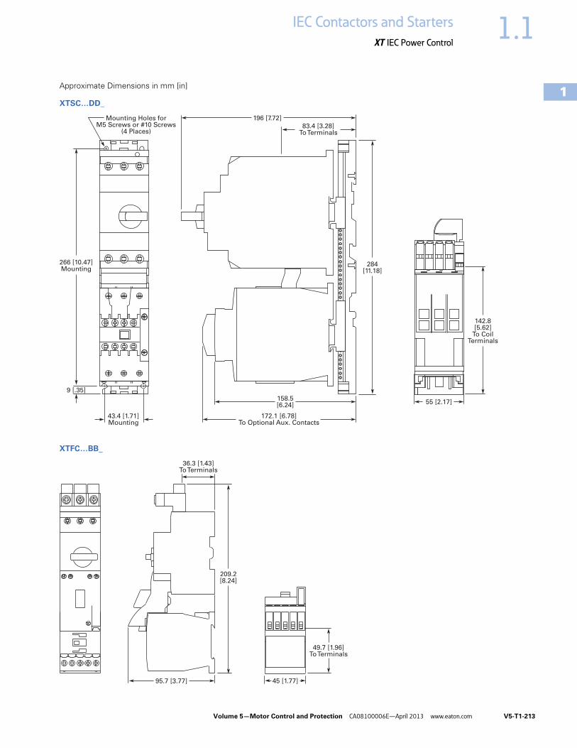
Volume 5—Motor Control and Protection CA08100006E—April 2013 www.eaton.com V5-T1-213
1
1
1
1
1
1
1
1
1
1
1
1
1
1
1
1
1
1
1
1
1
1
1
1
1
1
1
1
1
1
1.1IEC Contactors and Starters
XT IEC Power Control
Approximate Dimensions in mm [in]
XTSC…DD_
XTFC…BB_
142.8[5.62]
To CoilTerminals
83.4 [3.28]To Terminals
196 [7.72]
158.5[6.24]
172.1 [6.78]To Optional Aux. Contacts
Mounting Holes forM5 Screws or #10 Screws
(4 Places)
55 [2.17]
43.4 [1.71]Mounting
266 [10.47]Mounting
9 [.35]
284[11.18]
49.7 [1.96]To Terminals
45 [1.77]
36.3 [1.43]To Terminals
95.7 [3.77]
209.2[8.24]

V5-T1-214 Volume 5—Motor Control and Protection CA08100006E—April 2013 www.eaton.com
1
1
1
1
1
1
1
1
1
1
1
1
1
1
1
1
1
1
1
1
1
1
1
1
1
1
1
1
1
1
1.1 IEC Contactors and Starters
XT IEC Power Control
Approximate Dimensions in mm [in]
XTFR…BB_
XTFC…BC_
49.7 [1.96]To Terminals
90.3[3.55]
36.3 [1.43]To Terminals
95.3[3.75]
214.2[8.43]
86.8 [3.42]To Terminals
45.2[1.78]
61.3 [2.41]To Terminals
Mounting Holesfor M4 Screwsor #8 Screws
(4 Places)
124.3[4.89]
34 [1.34]Mounting
210.8 [8.30]Mounting
9 [.35]
228.8[9.01]
235.7[9.28]
266.7[10.50]

Volume 5—Motor Control and Protection CA08100006E—April 2013 www.eaton.com V5-T1-215
1
1
1
1
1
1
1
1
1
1
1
1
1
1
1
1
1
1
1
1
1
1
1
1
1
1
1
1
1
1
1.1IEC Contactors and Starters
XT IEC Power Control
Approximate Dimensions in mm [in]
XTFR…BC_
XTFC…DD_
86.8 [3.42]To Terminals
89.6 [3.53]
61.3 [2.41]To Terminals
124.3 [4.89]
228.8[9.01]
235.4[9.27]
266.4[10.49]
Mounting Holes forM4 Screws or #8 Screws
(8 Places)
45 [1.77]
79 [3.11] 5.3 [.21]
210.8[8.30]
9 [.35]
34 [1.34]
142.8[5.62]
To CoilTerminals
55 [2.17]158.5 [6.24]
172.1 [6.78] To Optional Aux. Contacts
86 [3.39]To Line SideConnector
Mounting Holes forM5 Screws or #10 Screws
(4 Places)
284[11.18]
266 [10.47]Mounting
43.4 [1.71]Mounting
9 [.35]
297[11.69]

V5-T1-216 Volume 5—Motor Control and Protection CA08100006E—April 2013 www.eaton.com
1
1
1
1
1
1
1
1
1
1
1
1
1
1
1
1
1
1
1
1
1
1
1
1
1
1
1
1
1
1
1.1 IEC Contactors and Starters
XT IEC Power Control
XT Electronic Manual Motor Protector ContentsDescription Page
Relays and Timers . . . . . . . . . . . . . . . . . . . . . . . . . V5-T1-3
Miniature Controls . . . . . . . . . . . . . . . . . . . . . . . . . V5-T1-18
Contactors and Starters . . . . . . . . . . . . . . . . . . . . V5-T1-35
Thermal Overload Relays . . . . . . . . . . . . . . . . . . . V5-T1-128
C440/XT Electronic Overload Relay . . . . . . . . . . . V5-T1-141
Manual Motor Protectors . . . . . . . . . . . . . . . . . . . V5-T1-157
Combination Motor Controllers . . . . . . . . . . . . . . . V5-T1-193
XT Electronic Manual Motor Protector Catalog Number Selection . . . . . . . . . . . . . . . . V5-T1-217
Product Selection . . . . . . . . . . . . . . . . . . . . . . . V5-T1-218
Accessories . . . . . . . . . . . . . . . . . . . . . . . . . . . V5-T1-220
Technical Data and Specifications . . . . . . . . . . V5-T1-226
Dimensions . . . . . . . . . . . . . . . . . . . . . . . . . . . V5-T1-228
Reference Data . . . . . . . . . . . . . . . . . . . . . . . . . . . V5-T1-229
XT Electronic Manual Motor ProtectorProduct DescriptionThe XT Electronic Manual Motor Protector provides the same functionality as the XT thermal manual motor protector, but with an added level of flexibility and selectability. The XTPE incorporates electronic control technology to enable more options and larger dial setting ranges. The trip units are interchangeable, allowing users to exchange as needed using the same base. The reduced number of part numbers decreases bill of material complexity while reducing inventory demands. The XTPE electronic manual motor protector includes the following features:
● 4:1 max to min overcurrent dial setting range
● Selectable trip class (5, 10, 15, 20)
● Interchangeable trip units● Three base units (12, 32
and 65A)● Common accessories with
the XTPR
Features and Benefits
Advanced Trip Unit
In addition to the selectability, the XTPE is also available with an advanced trip unit that can communicate system data and protector data thru SmartWire-DT. SmartWire-DT is an innovative cost effective connection technology that enables quick installation of control wiring to the starter through a single green cable. When on SmartWire-DT, the XTPE can communicate the following:
● Current Values ● Maximum phase current● Overload warning
● Diagnostics Data● Overload fault● Cause of trip
(overcurrent or short circuit)
● Phase loss● Trip via TEST
● Status Messages● Control unit type● Overload setting● Time-lag● Switching status
XTPE Electronic MMP
The XTPE Electronic MMP provides the selectability, control, and insight options that give panel builders and OEMs the solutions necessary to enhance motor control designs while reducing total costs.
Standards and Certifications● CE approved● UL Listed File No. E36332● UL 508 group motor and
Type E● IEC/EN 60947● CSA File 012528,
Class 3211-05

Volume 5—Motor Control and Protection CA08100006E—April 2013 www.eaton.com V5-T1-217
1
1
1
1
1
1
1
1
1
1
1
1
1
1
1
1
1
1
1
1
1
1
1
1
1
1
1
1
1
1
1.1IEC Contactors and Starters
XT IEC Power Control
Catalog Number Selection
XT—Manual Motor Protector
XT—Combinations
XT PE 004 B CS
TypePE = Electronic MMP
DesignationXT = XT line of IEC control
Overload Release1P2 = 0.3–1.2A004 = 1–4A012 = 3–12A 032 = 8–32A065 = 16–65A
Trip TypeCS = StandardCA = Advanced (SmartWire-DT)MMP Frame
B = 45 mmD = 55 mm
TypeFCE = Electronic
combination motor controller
DesignationXT = XT line of IEC control
Contactor FrameC = 45 mm
XT FCE 004 B C CS A
Overload Release1P2 = 0.3–1.2A004 = 1–4A012 = 3–12A032 = 8–32A
MMP FrameB = 45 mm
Trip TypeCS = Selectable class 5, 10, 15, 20CA = Selectable, advanced
Coil VoltageA = 110V 50 Hz, 120V 60 HzB = 220V 50 Hz, 240V 60 HzF = 230V 50 HzT = 24V 50/60 HzTD = 24 Vdc
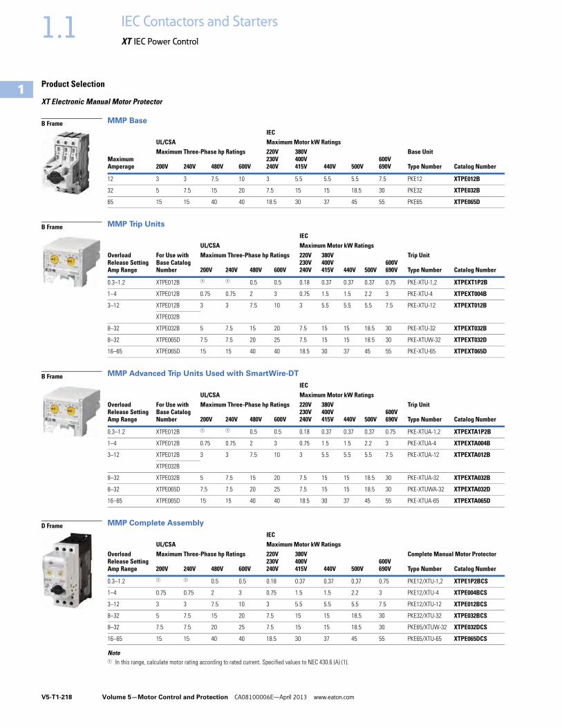
V5-T1-218 Volume 5—Motor Control and Protection CA08100006E—April 2013 www.eaton.com
1
1
1
1
1
1
1
1
1
1
1
1
1
1
1
1
1
1
1
1
1
1
1
1
1
1
1
1
1
1
1.1 IEC Contactors and Starters
XT IEC Power Control
Product Selection
XT Electronic Manual Motor Protector
MMP Base
MMP Trip Units
MMP Advanced Trip Units Used with SmartWire-DT
MMP Complete Assembly
Note1 In this range, calculate motor rating according to rated current. Specified values to NEC 430.6 (A) (1).
Maximum Amperage
UL/CSA IEC
Base Unit Maximum Motor kW Ratings220V230V240V
380V400V415V 440V 500V
600V690V
Maximum Three-Phase hp Ratings
200V 240V 480V 600V Type Number Catalog Number
12 3 3 7.5 10 3 5.5 5.5 5.5 7.5 PKE12 XTPE012B
32 5 7.5 15 20 7.5 15 15 18.5 30 PKE32 XTPE032B
65 15 15 40 40 18.5 30 37 45 55 PKE65 XTPE065D
Overload Release Setting Amp Range
For Use with Base Catalog Number
UL/CSAIEC
Trip UnitMaximum Motor kW Ratings
Maximum Three-Phase hp Ratings 220V230V240V
380V400V415V 440V 500V
600V690V200V 240V 480V 600V Type Number Catalog Number
0.3–1.2 XTPE012B 1 1 0.5 0.5 0.18 0.37 0.37 0.37 0.75 PKE-XTU-1,2 XTPEXT1P2B
1–4 XTPE012B 0.75 0.75 2 3 0.75 1.5 1.5 2.2 3 PKE-XTU-4 XTPEXT004B
3–12 XTPE012B 3 3 7.5 10 3 5.5 5.5 5.5 7.5 PKE-XTU-12 XTPEXT012B
XTPE032B
8–32 XTPE032B 5 7.5 15 20 7.5 15 15 18.5 30 PKE-XTU-32 XTPEXT032B
8–32 XTPE065D 7.5 7.5 20 25 7.5 15 15 18.5 30 PKE-XTUW-32 XTPEXT032D
16–65 XTPE065D 15 15 40 40 18.5 30 37 45 55 PKE-XTU-65 XTPEXT065D
Overload Release Setting Amp Range
For Use with Base Catalog Number
UL/CSA IEC
Trip Unit Maximum Motor kW Ratings
Maximum Three-Phase hp Ratings 220V230V240V
380V400V415V 440V 500V
600V690V200V 240V 480V 600V Type Number Catalog Number
0.3–1.2 XTPE012B 1 1 0.5 0.5 0.18 0.37 0.37 0.37 0.75 PKE-XTUA-1,2 XTPEXTA1P2B
1–4 XTPE012B 0.75 0.75 2 3 0.75 1.5 1.5 2.2 3 PKE-XTUA-4 XTPEXTA004B
3–12 XTPE012B 3 3 7.5 10 3 5.5 5.5 5.5 7.5 PKE-XTUA-12 XTPEXTA012B
XTPE032B
8–32 XTPE032B 5 7.5 15 20 7.5 15 15 18.5 30 PKE-XTUA-32 XTPEXTA032B
8–32 XTPE065D 7.5 7.5 20 25 7.5 15 15 18.5 30 PKE-XTUWA-32 XTPEXTA032D
16–65 XTPE065D 15 15 40 40 18.5 30 37 45 55 PKE-XTUA-65 XTPEXTA065D
Overload Release Setting Amp Range
UL/CSA IEC
Complete Manual Motor ProtectorMaximum Motor kW Ratings
Maximum Three-Phase hp Ratings 220V230V240V
380V400V415V 440V 500V
600V690V200V 240V 480V 600V Type Number Catalog Number
0.3–1.2 1 1 0.5 0.5 0.18 0.37 0.37 0.37 0.75 PKE12/XTU-1,2 XTPE1P2BCS
1–4 0.75 0.75 2 3 0.75 1.5 1.5 2.2 3 PKE12/XTU-4 XTPE004BCS
3–12 3 3 7.5 10 3 5.5 5.5 5.5 7.5 PKE12/XTU-12 XTPE012BCS
8–32 5 7.5 15 20 7.5 15 15 18.5 30 PKE32/XTU-32 XTPE032BCS
8–32 7.5 7.5 20 25 7.5 15 15 18.5 30 PKE65/XTUW-32 XTPE032DCS
16–65 15 15 40 40 18.5 30 37 45 55 PKE65/XTU-65 XTPE065DCS
B Frame
B Frame
B Frame
D Frame

Volume 5—Motor Control and Protection CA08100006E—April 2013 www.eaton.com V5-T1-219
1
1
1
1
1
1
1
1
1
1
1
1
1
1
1
1
1
1
1
1
1
1
1
1
1
1
1
1
1
1
1.1IEC Contactors and Starters
XT IEC Power Control
MMP Used with SmartWire-DT—Complete Assembly
UL 508 Type E XT Electronic Combination Motor Controllers—Complete Assembly Including Trip Unit
B Frame Electronic MMP with C Frame Contactor
Notes1 In this range, calculate motor rating according to rated current. Specified values to NEC 430.6 (A) (1).2 Complete the catalog number by replacing the underscore (_) with the coil suffix from Page V5-T1-238.3 SCCR: 14 kA, 600 Vac4 SCCR: 18 kA, 480 Vac
Overload Release Setting Amp Range
UL/CSAIEC
Complete Manual Motor ProtectorMaximum Motor kW Ratings
Maximum Motor hp Ratings 220V230V240V
380V400V415V 440V 500V
600V690V200V 230V 460V 575V Type Number Catalog Number
0.3–1.2 1 1 0.5 0.5 0.18 0.37 0.37 0.37 0.75 PKE12/XTUA-1,2 XTPE1P2BCA
1–4 0.75 0.75 2 3 0.75 1.5 1.5 2.2 3 PKE12/XTUA-4 XTPE004BCA
3–12 3 3 7.5 10 3 5.5 5.5 5.5 7.5 PKE12/XTUA-12 XTPE012BCA
8–32 5 7.5 15 20 7.5 15 15 18.5 30 PKE32/XTUA-32 XTPE032BCA
Overload Release Setting Amp Range
UL/CSA
Catalog NumberStandard
Catalog NumberWith SmartWire-DT
Maximum Three-Phase hp Ratings Maximum Single-Phase hp Ratings
200V 240V380Y/415V
480Y/277V
600Y/347V 115V 200V 240V
0.3–1.2 1 1 1 1 0.5 1 1 1 XTFCE1P2BCCS_ 3 XTFCE1P2BCCATD 3
1–4 0.75 0.75 1.5 2 — 0.125 0.25 0.33 XTFCE004BCCS_ 4 XTFCE004BCCATD 4
3–12 3 3 5 7.5 — 0.5 1 1.5 XTFCE012BCCS_ 4 XTFCE012BCCATD 4
8–32 5 5 10 15 — 1.5 3 3 XTFCE032BCCS_ 4 XTFCE032BCCATD 4
B Frame
B Frame

V5-T1-220 Volume 5—Motor Control and Protection CA08100006E—April 2013 www.eaton.com
1
1
1
1
1
1
1
1
1
1
1
1
1
1
1
1
1
1
1
1
1
1
1
1
1
1
1
1
1
1
1.1 IEC Contactors and Starters
XT IEC Power Control
Accessories
Auxiliary Contacts
Side-Mount Auxiliary Contacts
Can be fitted on the right side of manual motor protectors (XTPB, XTPR, XTPM) and manual transformer protectors (XTPT) and can be combined with XTPAXSATR_ and XTPAXFA_ trip indicating auxiliary contact.
Front-Mount Auxiliary Contacts
Can be fitted to manual motor protectors (XTPB, XTPR, XTPM) and manual transformer protectors (XTPT). 45 mm (XTPR…B and XTPB) or 55 mm (XTPR…D) widths of manual motor protectors remain unchanged.
Note1 Orders must be placed in multiples of package quantity listed.
ContactConfiguration Contact Sequence
Pkg. Qty. 1
Screw TerminalCatalog Number
1NO-1NC 5 XTPAXSA11
1NO-2NC 5 XTPAXSA12
2NO-1NC 5 XTPAXSA21
ContactConfiguration Contact Sequence
Pkg. Qty. 1
Screw TerminalCatalog Number
1NO-1NC 5 XTPAXFA11
XTPAXSA_
L1 L2 L3
XTPAXSA11
1.14 1.22
1.13 1.21
1.14 1.22 1.32
1.13 1.21 1.31
L1 L2 L3
XTPAXSA12
1.14 1.22 1.34
1.13 1.21 1.33
L1 L2 L3
XTPAXSA21
XTPAXFA11
1.54 1.62
1.53 1.61
L1 L2 L3
XTPAXFA11

Volume 5—Motor Control and Protection CA08100006E—April 2013 www.eaton.com V5-T1-221
1
1
1
1
1
1
1
1
1
1
1
1
1
1
1
1
1
1
1
1
1
1
1
1
1
1
1
1
1
1
1.1IEC Contactors and Starters
XT IEC Power Control
Side-Mount Trip Indicating Auxiliary Contacts
Can be fitted on the right side of manual motor protectors. Can be combined with standard auxiliary contacts. Trip indication: A. General trip indication (overload) B. Short-circuit trip. Local short-circuit indication by red indicator, manually resettable.
Note1 Orders must be placed in multiples of package quantity listed.
ContactConfiguration Contact Sequence
Pkg.Qty. 1
For Use with… Catalog Number
2 x 1NO 2 XTPE XTPAXSATR20
2 x 1NC 2 XTPE XTPAXSATR02
XTPAXSATR_
4.44 4.14
“+”4.43
“ ”4.13
“+”“ >”
On/Off
“+”“ >”
Trip “+”
L1L2L3
L1L2L3
4.32 4.22
“+”4.31
“ ”4.21
On/Off
“+”“ >”
Trip “+”
L1L2L3
“+”“ >”
L1L2L3

V5-T1-222 Volume 5—Motor Control and Protection CA08100006E—April 2013 www.eaton.com
1
1
1
1
1
1
1
1
1
1
1
1
1
1
1
1
1
1
1
1
1
1
1
1
1
1
1
1
1
1
1.1 IEC Contactors and Starters
XT IEC Power Control
Additional Accessories
Shunt Release
Can be used to trip the manual motor protector from a remote location. Can be fitted on the left side of manual motor protectors. Cannot be combined with the XTPAXUVR. DC: Intermittent operation 5 sec.
Undervoltage Release
Can be used to trip the manual motor protector from a remote location. Can be fitted on left side manual motor protectors. Cannot be combined with XTPAXSR. When combined with a circuit breaker, it can be used as emergency-stop device to IEC/EN 60204.
Note1 Orders must be placed in multiples of package quantity listed.
Pkg.Qty. 1
Screw TerminalCatalog Number
2 XTPAXSR24V50H
2 XTPAXSR48V50H
2 XTPAXSR110V50H
2 XTPAXSR120V60H
2 XTPAXSR208V60H
2 XTPAXSR220V50H
2 XTPAXSR230V50H
2 XTPAXSR240V50H
2 XTPAXSR240V60H
2 XTPAXSR380V50H
2 XTPAXSR400V50H
2 XTPAXSR415V50H
2 XTPAXSR440V60H
2 XTPAXSR480V60H
2 XTPAXSR24VDC
2 XTPAXSR48VDC
2 XTPAXSR60VDC
2 XTPAXSR110VDC
2 XTPAXSR125VDC
2 XTPAXSR220VDC
2 XTPAXSR250VDC
XTPAXSR_
Contact Sequence
C1
C2
Pkg.Qty. 1
Screw TerminalCatalog Number
2 XTPAXUVR24V50H
2 XTPAXUVR24V60H
2 XTPAXUVR48V50H
2 XTPAXUVR60V50H
2 XTPAXUVR110V50H
2 XTPAXUVR120V60H
2 XTPAXUVR208V60H
2 XTPAXUVR220V50H
2 XTPAXUVR230V50H
2 XTPAXUVR240V50H
2 XTPAXUVR240V60H
2 XTPAXUVR380V50H
2 XTPAXUVR400V50H
2 XTPAXUVR415V50H
2 XTPAXUVR440V60H
2 XTPAXUVR480V60H
2 XTPAXUVR600V60H
XTPAXUVR_
Contact Sequence
D1
D2
U

Volume 5—Motor Control and Protection CA08100006E—April 2013 www.eaton.com V5-T1-223
1
1
1
1
1
1
1
1
1
1
1
1
1
1
1
1
1
1
1
1
1
1
1
1
1
1
1
1
1
1
1.1IEC Contactors and Starters
XT IEC Power Control
IP65 Rotary Handle Mechanism 123
Three-Phase Commoning Links 7
For parallel power feed to several manual motor protectors on terminals 1, 3 and 5.
Shroud for Unused Terminals of Three-Phase Commoning Links
Incoming Terminals for Three-Phase Commoning Link 8
Notes1 Plug-in connection shafts, XTPAXRHMSFT_ can be cut to desired length for mounting depths of 100–240 mm. Carrier
with extension shaft included.2 With ON/OFF switch position and “+” (tripped), lockable with 3 padlocks, 4–8 mm hasp. Can be locked in the
OFF position, if required.3 Rotary handle mechanisms ship with door interlock disabled. See instruction publication with product for how to
enable door interlock.4 Orders must be placed in multiples of package quantity listed. 5 For use on main switches to IEC/EN 60204.6 For use on main switches with emergency-stop function to IEC/EN 60204.7 Protected against accidental contact. Frame B short-circuit proof Ue = 690V, Iu = 63A. Frame B links can be combined by
rotating mounting.8 For three-phase commoning link, protected against accidental contact, Ue = 690V, Iu = 63A;
For conductor cross-sections: 2.5–25 mm2 stranded; 2.5–16 mm2 flexible with ferrules, AWG 14-6.
DescriptionEnclosure Rating
Pkg. Qty. 4 Catalog Number
Complete Kits—Includes Handle, Shaft and Required Hardware
Rotary handle mechanism—black 5 IP65NEMA 12UL/CSA 4X
1 XTPEXRHMB
Rotary handle mechanism—red/yellow 6 1 XTPEXRHMRY
Rotary handle mechanism—black—rotated 90° from vertical 5 1 XTPEXRHM90B
Rotary handle mechanism—red/yellow—rotated 90° from vertical 6 1 XTPEXRHM90RY
For Use with…Qty.MMP
Length ofLink (mm)
UnitWidth (mm)
Pkg.Qty. 4 Catalog Number
MMP with no side-mounted auxiliaries or voltage releases
2 90 45 10 XTPAXCLKA2
3 135 45 10 XTPAXCLKA3
4 180 45 10 XTPAXCLKA4
5 225 45 10 XTPAXCLKA5
Each MMP with one auxiliary contact or trip-indicating auxiliary contact fitted on the right
2 99 45 + 9 10 XTPAXCLKB2
3 153 45 + 9 10 XTPAXCLKB3
4 207 45 + 9 10 XTPAXCLKB4
5 261 45 + 9 10 XTPAXCLKB5
Each MMP with an auxiliary contact and trip-indicating auxiliary contact mounted on the right or a voltage release mounted on the left.
2 108 45 + 18 10 XTPAXCLKC2
For Use with… DescriptionPkg.Qty. 4 Catalog Number
Frame BXTPE
To cover unused terminals on three-phase commoning link. Protected against direct contact.
20 XTPAXUTS
For Use with…Pkg.Qty. 4 Catalog Number
Frame B XTPE 5 XTPAXIT
XTPAXRHM_
XTPAXUTS
XTPAXIT
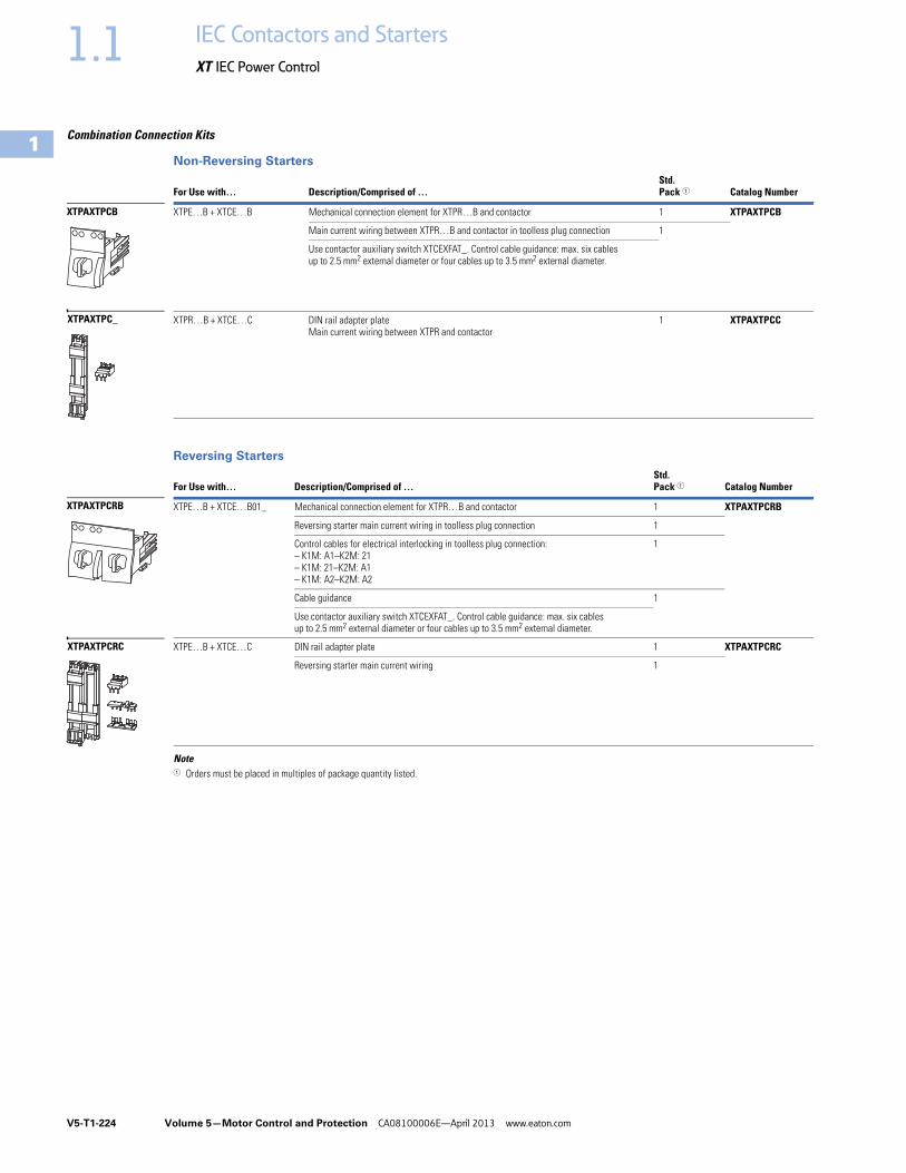
V5-T1-224 Volume 5—Motor Control and Protection CA08100006E—April 2013 www.eaton.com
1
1
1
1
1
1
1
1
1
1
1
1
1
1
1
1
1
1
1
1
1
1
1
1
1
1
1
1
1
1
1.1 IEC Contactors and Starters
XT IEC Power Control
Combination Connection Kits
Non-Reversing Starters
Reversing Starters
Note1 Orders must be placed in multiples of package quantity listed.
For Use with… Description/Comprised of …Std. Pack 1 Catalog Number
XTPE…B + XTCE…B Mechanical connection element for XTPR…B and contactor 1 XTPAXTPCB
Main current wiring between XTPR…B and contactor in toolless plug connection 1
Use contactor auxiliary switch XTCEXFAT_. Control cable guidance: max. six cables up to 2.5 mm2 external diameter or four cables up to 3.5 mm2 external diameter.
XTPR…B + XTCE…C DIN rail adapter plateMain current wiring between XTPR and contactor
1 XTPAXTPCC
For Use with… Description/Comprised of …Std. Pack 1 Catalog Number
XTPE…B + XTCE…B01_ Mechanical connection element for XTPR…B and contactor 1 XTPAXTPCRB
Reversing starter main current wiring in toolless plug connection 1
Control cables for electrical interlocking in toolless plug connection:– K1M: A1–K2M: 21– K1M: 21–K2M: A1– K1M: A2–K2M: A2
1
Cable guidance 1
Use contactor auxiliary switch XTCEXFAT_. Control cable guidance: max. six cables up to 2.5 mm2 external diameter or four cables up to 3.5 mm2 external diameter.
XTPE…B + XTCE…C DIN rail adapter plate 1 XTPAXTPCRC
Reversing starter main current wiring 1
XTPAXTPCB
XTPAXTPC_
XTPAXTPCRB
XTPAXTPCRC

Volume 5—Motor Control and Protection CA08100006E—April 2013 www.eaton.com V5-T1-225
1
1
1
1
1
1
1
1
1
1
1
1
1
1
1
1
1
1
1
1
1
1
1
1
1
1
1
1
1
1
1.1IEC Contactors and Starters
XT IEC Power Control
Electrical Connection Module
DIN Rail Adapter Plates
Note1 Orders must be placed in multiples of package quantity listed.
For Use with… Description/Comprised of …Std. Pack 1 Catalog Number
XTPE…B + XTCE…C Main current wiring between XTPR…B and contactor 5 XTPAXECMC
For Use with… Description/Comprised of …Std. Pack 1 Catalog Number
XTPAXTPCBXTPAXTPCRB
45 mm wide adapter plate with one DIN rail 4 XTPAXTPCPB
Connection element for side-by-side positioning of further plates
XTPE…B +XTCE…B or C
SmartWire-DT communication link 1 PKE-SWD-32
XTPAXECM_
XTPAXTPCPB
PKE-SWD-32
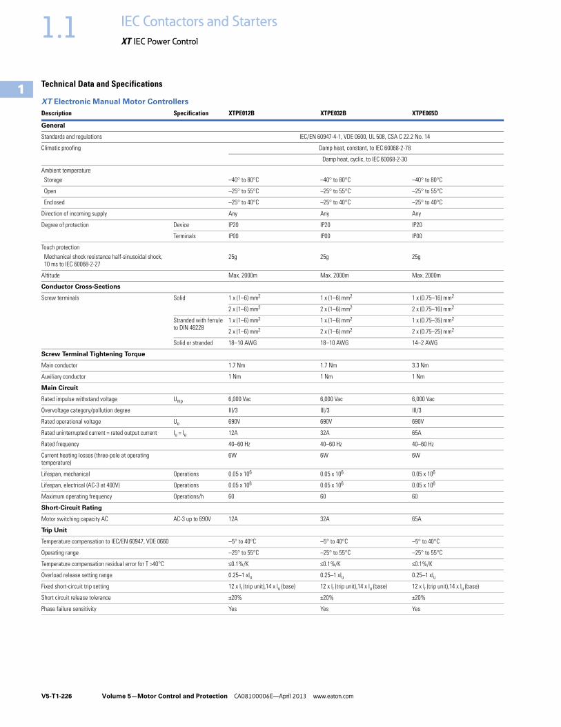
V5-T1-226 Volume 5—Motor Control and Protection CA08100006E—April 2013 www.eaton.com
1
1
1
1
1
1
1
1
1
1
1
1
1
1
1
1
1
1
1
1
1
1
1
1
1
1
1
1
1
1
1.1 IEC Contactors and Starters
XT IEC Power Control
Technical Data and Specifications
XT Electronic Manual Motor Controllers
Description Specification XTPE012B XTPE032B XTPE065D
General
Standards and regulations IEC/EN 60947-4-1, VDE 0600, UL 508, CSA C 22.2 No. 14
Climatic proofing Damp heat, constant, to IEC 60068-2-78
Damp heat, cyclic, to IEC 60068-2-30
Ambient temperatureStorage –40° to 80°C –40° to 80°C –40° to 80°C
Open –25° to 55°C –25° to 55°C –25° to 55°C
Enclosed –25° to 40°C –25° to 40°C –25° to 40°C
Direction of incoming supply Any Any Any
Degree of protection Device IP20 IP20 IP20
Terminals IP00 IP00 IP00
Touch protectionMechanical shock resistance half-sinusoidal shock, 10 ms to IEC 60068-2-27
25g 25g 25g
Altitude Max. 2000m Max. 2000m Max. 2000m
Conductor Cross-Sections
Screw terminals Solid 1 x (1–6) mm2 1 x (1–6) mm2 1 x (0.75–16) mm2
2 x (1–6) mm2 2 x (1–6) mm2 2 x (0.75–16) mm2
Stranded with ferrule to DIN 46228
1 x (1–6) mm2 1 x (1–6) mm2 1 x (0.75–35) mm2
2 x (1–6) mm2 2 x (1–6) mm2 2 x (0.75–25) mm2
Solid or stranded 18–10 AWG 18–10 AWG 14–2 AWG
Screw Terminal Tightening Torque
Main conductor 1.7 Nm 1.7 Nm 3.3 Nm
Auxiliary conductor 1 Nm 1 Nm 1 Nm
Main Circuit
Rated impulse withstand voltage Ump 6,000 Vac 6,000 Vac 6,000 Vac
Overvoltage category/pollution degree III/3 III/3 III/3
Rated operational voltage Ue 690V 690V 690V
Rated uninterrupted current = rated output current Iu = Ie 12A 32A 65A
Rated frequency 40–60 Hz 40–60 Hz 40–60 Hz
Current heating losses (three-pole at operating temperature)
6W 6W 6W
Lifespan, mechanical Operations 0.05 x 10⁶ 0.05 x 10⁶ 0.05 x 10⁶
Lifespan, electrical (AC-3 at 400V) Operations 0.05 x 10⁶ 0.05 x 10⁶ 0.05 x 10⁶
Maximum operating frequency Operations/h 60 60 60
Short-Circuit Rating
Motor switching capacity AC AC-3 up to 690V 12A 32A 65A
Trip Unit
Temperature compensation to IEC/EN 60947, VDE 0660 –5° to 40°C –5° to 40°C –5° to 40°C
Operating range –25° to 55°C –25° to 55°C –25° to 55°C
Temperature compensation residual error for T >40°C <0.1%/K <0.1%/K <0.1%/K
Overload release setting range 0.25–1 xlu 0.25–1 xlu 0.25–1 xlu
Fixed short-circuit trip setting 12 x lr (trip unit),14 x lu (base) 12 x lr (trip unit),14 x lu (base) 12 x lr (trip unit),14 x lu (base)
Short circuit release tolerance ±20% ±20% ±20%
Phase failure sensitivity Yes Yes Yes

Volume 5—Motor Control and Protection CA08100006E—April 2013 www.eaton.com V5-T1-227
1
1
1
1
1
1
1
1
1
1
1
1
1
1
1
1
1
1
1
1
1
1
1
1
1
1
1
1
1
1
1.1IEC Contactors and Starters
XT IEC Power Control
Trip Characteristics
XT Electronic Manual Motor Controllers
XTPE …

V5-T1-228 Volume 5—Motor Control and Protection CA08100006E—April 2013 www.eaton.com
1
1
1
1
1
1
1
1
1
1
1
1
1
1
1
1
1
1
1
1
1
1
1
1
1
1
1
1
1
1
1.1 IEC Contactors and Starters
XT IEC Power Control
DimensionsApproximate Dimensions in Inches (mm)
XT Electronic MMP—B Frame
XT Electronic CMC With C Frame Contactor
XT Electronic MMP—D Frame
1.77(45.0)
4.72 (120.0)
3.79 (96.2)
3.98(101.0)
5.71 (145.0)
4.77 (121.2)
3.66 (92.9)To Line
Side Adapter
10.63 (269.9)
To Line Side
Adapter
9.46(240.3)
9.01(228.8)
MountingRail4.87 (123.8)
Line SideAdapter
1.76(44.6)
4.65 (118.0)
2.22(56.5)
2.17(55.0)
1.38(35.0)
6.30(160.0)
0.57(14.5)
1.28(32.5)
0.22 (5.5)
5.00 (127.0)6.77 (172.0)
7.36 (187.0)

Volume 5—Motor Control and Protection CA08100006E—April 2013 www.eaton.com V5-T1-229
1
1
1
1
1
1
1
1
1
1
1
1
1
1
1
1
1
1
1
1
1
1
1
1
1
1
1
1
1
1
1.1IEC Contactors and Starters
XT IEC Power Control
Reference DataType 2 Coordination . . . . . . . . . . . . . . . . . . . . . . . V5-T1-230
Approvals for World Markets . . . . . . . . . . . . . . . . V5-T1-239
IEC Utilization Categories . . . . . . . . . . . . . . . . . . V5-T1-242
Motor Ratings Data . . . . . . . . . . . . . . . . . . . . . . . V5-T1-245
Ampacities of Insulated Conductors (Based on 2005 NEC) . . . . . . . . . . . . . . . . . . . . V5-T1-249
Type 1 and Type 2 Coordination
What is it?The International Electrotechnical Commission (IEC) developed short-circuit performance criteria for contactors and starters called Type 1 coordination and Type 2 coordination. This defines motor controller protection levels following a short-circuit fault. In order to achieve this performance, the combination of a motor controller (contactor or starter) and short-circuit protective device (manual motor protector, circuit breaker or fuse) must meet the following criteria as specified by IEC 60947-4-1—Low voltage switchgear and controlgear—Part 4-1: Contactors and motor-starters—Electromechanical contactors and motor-starters:
Type 1 Coordination Type 1 Coordination requires that under short-circuit conditions, the contactor or starter shall cause no danger to persons or installation and may not be suitable for further service without repair and replacement of parts.
In this case, significant damage is allowed to the contactor/starter (for example, contact welding, burning or disintegration) and the overload relay (for example, component harm or heater element burn-out).
Type 2 Coordination Type 2 Coordination requires that under short-circuit conditions, the contactor or starter shall cause no danger to persons or installation and shall be suitable for further use. The risk of contact welding is recognized, in which case the manufacturer shall indicate the measures to be taken as regards to the maintenance of the equipment.

V5-T1-230 Volume 5—Motor Control and Protection CA08100006E—April 2013 www.eaton.com
1
1
1
1
1
1
1
1
1
1
1
1
1
1
1
1
1
1
1
1
1
1
1
1
1
1
1
1
1
1
1.1 IEC Contactors and Starters
XT IEC Power Control
Type 2 Coordination
400, xx415V Type 2 Coordination—MMC
NotesSee Page V5-T1-238 for more information on wye-delta (star delta) applications. 1 Values in parentheses ( ) are for Type 1 Coordination.2 Underscore (_) indicates magnet coil suffix required. See Page V5-T1-238.
P(kW)
Ie(A)
Iq(kA)
MMPCatalog Number
ContactorCatalog Number 2
MMCCatalog Number 2
0.06 0.21 50 (150) 1 XTPRP25BC1 XTCE007B10_ XTSCP25BB_
0.09 0.31 50 (150) 1 XTPRP40BC1 XTCE007B10_ XTSCP40BB_
0.12 0.41 50 (150) 1 XTPRP63BC1 XTCE007B10_ XTSCP63BB_
0.18 0.60 50 (150) 1 XTPRP63BC1 XTCE007B10_ XTSCP63BB_
0.25 0.80 50 (150) 1 XTPR001BC1 XTCE007B10_ XTSC001BB_
0.37 1.10 50 (150) 1 XTPR1P6BC1 XTCE007B10_ XTSC1P6BB_
0.55 1.50 50 (150) 1 XTPR1P6BC1 XTCE007B10_ XTSC1P6BB_
0.75 1.90 50 (150) 1 XTPR2P5BC1 XTCE007B10_ XTSC2P5BB_
1.10 2.60 50 (150) 1 XTPR004BC1 XTCE007B10_ XTSC004BB_
1.50 3.60 50 (150) 1 XTPR004BC1 XTCE007B10_ XTSC004BB_
2.20 5.00 50 (150) 1 XTPR6P3BC1 XTCE007B10_ XTSC6P3BB_
3.00 6.60 50 (150) 1 XTPR010BC1 XTCE018C10_ XTSC010BC_
4.00 8.50 50 (150) 1 XTPR010BC1 XTCE018C10_ XTSC010BC_
5.50 11.3 50 XTPR012BC1 XTCE018C10_ XTSC012BC_
7.50 16.0 50 XTPR016BC1 XTCE018C10_ XTSC016BC_
11.0 21.7 50 XTPR025BC1 XTCE025C10_ XTSC025BC_
15.0 29.3 50 XTPR032BC1 XTCE032C10_ XTSC032BC_
5.50 11.3 50 XTPR016DC1 XTCE018C10_ XTSC016DC_
7.50 16.0 50 XTPR016DC1 XTCE018C10_ XTSC016DC_
11.0 21.7 50 XTPR025DC1 XTCE025C10_ XTSC025DC_
15.0 29.3 50 XTPR032DC1 XTCE032C10_ XTSC032DC_
18.5 36.0 50 XTPR040DC1 XTCE040D00_ XTSC040DD_
22.0 41.0 50 XTPR050DC1 XTCE050D00_ XTSC050DD_
30.0 55.0 50 XTPR058DC1 XTCE065D00_ XTSC058DD_
34.0 63.0 50 XTPR063DC1 XTCE065D00_ XTSC063DD_

Volume 5—Motor Control and Protection CA08100006E—April 2013 www.eaton.com V5-T1-231
1
1
1
1
1
1
1
1
1
1
1
1
1
1
1
1
1
1
1
1
1
1
1
1
1
1
1
1
1
1
1.1IEC Contactors and Starters
XT IEC Power Control
480V Type 2 Coordination—MMC
600V Type 2 Coordination—MMC
NotesSee Page V5-T1-238 for more information on wye-delta (star delta) applications. 1 Values in parentheses ( ) are achieved without the current limiter.2 Underscore (_) indicates magnet coil suffix required. See Page V5-T1-238.
P(hp)
Ie(A)
Iq(kA)
MMPCatalog Number
Current LimiterCatalog Number
ContactorCatalog Number 2
MMCCatalog Number 2
1/2 0.24 65 XTPRP25BC1 — XTCE007B10_ XTSCP25BB_
1/2 0.32 65 XTPRP40BC1 — XTCE007B10_ XTSCP40BB_
1/2 0.51 65 XTPRP63BC1 — XTCE007B10_ XTSCP63BB_
1/2 0.74 65 XTPR001BC1 — XTCE007B10_ XTSC001BB_
1/2 0.94 65 XTPR001BC1 — XTCE007B10_ XTSC001BB_
3/4 1.32 65 XTPR1P6BC1 — XTCE007B10_ XTSC1P6BB_
1 1.72 65 XTPR2P5BC1 — XTCE018C10_ XTSC2P5BC_
2 2.55 65 XTPR004BC1 — XTCE018C10_ XTSC004BC_
2 3.10 65 XTPR004BC1 — XTCE018C10_ XTSC004BC_
3 4.55 65 (50) 1 XTPR6P3BC1 XTPAXCL XTCE018C10_ XTSC6P3BC_
3 6.15 65 (50) 1 XTPR6P3BC1 XTPAXCL XTCE018C10_ XTSC6P3BC_
7-1/2 8.40 65 (50) 1 XTPR010BC1 XTPAXCL XTCE018C10_ XTSC010BC_
7-1/2 11.0 65 (50) 1 XTPR012BC1 XTPAXCL XTCE018C10_ XTSC012BC_
10 14.5 65 (50) 1 XTPR016BC1 XTPAXCL XTCE018C10_ XTSC016BC_
10 20.0 65 (50) 1 XTPR020BC1 XTPAXCL XTCE025C10_ XTSC020BC_
20 20.0 65 XTPR025DC1 — XTCE040D00_ XTSC025DD_
25 27.0 65 XTPR032DC1 — XTCE040D00_ XTSC032DD_
25 32.0 65 XTPR032DC1 — XTCE040D00_ XTSC032DD_
30 37.5 65 XTPR040DC1 — XTCE040D00_ XTSC040DD_
40 40.5 65 XTPR050DC1 — XTCE050D00_ XTSC050DD_
40 50.5 65 XTPR058DC1 — XTCE065D00_ XTSC058DD_
40 64.0 65 XTPR063DC1 — XTCE065D00_ XTSC063DD_
P(hp)
Ie(A)
Iq(kA)
MMPCatalog Number
Current LimiterCatalog Number
ContactorCatalog Number 2
MMCCatalog Number 2
1/2 0.19 50 XTPRP25BC1 — XTCE007B10_ XTSCP25BB_
1/2 0.26 50 XTPRP40BC1 — XTCE007B10_ XTSCP40BB_
1/2 0.41 50 XTPRP63BC1 — XTCE007B10_ XTSCP63BB_
1/2 0.59 50 XTPRP63BC1 — XTCE007B10_ XTSCP63BB_
1/2 0.75 50 XTPR001BC1 — XTCE007B10_ XTSC001BB_
1 1.06 50 XTPR1P6BC1 — XTCE007B10_ XTSC1P6BB_
1 1.38 50 XTPR1P6BC1 — XTCE007B10_ XTSC1P6BB_
1-1/2 2.04 50 XTPR2P5BC1 — XTCE018C10_ XTSC2P5BC_
1-1/2 2.48 50 XTPR2P5BC1 — XTCE018C10_ XTSC2P5BC_
3 3.64 50 XTPR004BC1 — XTCE018C10_ XTSC004BC_
5 4.92 50 (18) 1 XTPR6P3BC1 XTPAXCL XTCE018C10_ XTSC6P3BC_
10 6.72 50 (18) 1 XTPR010BC1 XTPAXCL XTCE018C10_ XTSC010BC_
10 8.60 50 (18) 1 XTPR010BC1 XTPAXCL XTCE018C10_ XTSC010BC_
10 11.5 50 (18) 1 XTPR012BC1 XTPAXCL XTCE018C10_ XTSC012BC_
10 16.0 50 (18) 1 XTPR016BC1 XTPAXCL XTCE018C10_ XTSC016BC_
25 21.5 50 XTPR025DC1 — XTCE040D00_ XTSC025DD_
30 25.5 50 XTPR032DC1 — XTCE040D00_ XTSC032DD_
30 30.0 50 XTPR032DC1 — XTCE040D00_ XTSC032DD_
30 37.5 50 XTPR040DC1 — XTCE040D00_ XTSC050DD_
40 40.5 50 XTPR050DC1 — XTCE050D00_ XTSC050DD_
40 51.0 42 XTPR058DC1 — XTCE065D00_ XTSC058DD_
50 61.0 42 XTPR063DC1 — XTCE065D00_ XTSC063DD_

V5-T1-232 Volume 5—Motor Control and Protection CA08100006E—April 2013 www.eaton.com
1
1
1
1
1
1
1
1
1
1
1
1
1
1
1
1
1
1
1
1
1
1
1
1
1
1
1
1
1
1
1.1 IEC Contactors and Starters
XT IEC Power Control
400, 415V Type 2 Coordination—Contactor and Overload Relay (Motor Starter) with Fused Disconnect
NotesSee Page V5-T1-238 for more information on wye-delta (star delta) applications. 1 Underscore (_) indicates magnet coil code required. See Page V5-T1-238.
P(kW)
Ie(A)
Iq(kA)
FusesClass gG/gL
ContactorCatalog Number 1
Overload RelayCatalog Number
Assembled StarterCatalog Number 1
0.12 0.41 100 2 XTCE007B10_ XTOBP60BC1 XTAE007B10_P60
0.18 0.60 100 2 XTCE007B10_ XTOB001BC1 XTAE007B10_001
0.25 0.80 100 4 XTCE007B10_ XTOB001BC1 XTAE007B10_001
0.37 1.10 100 4 XTCE007B10_ XTOB1P6BC1 XTAE007B10_1P6
0.55 1.50 100 4 XTCE007B10_ XTOB1P6BC1 XTAE007B10_1P6
0.75 1.90 100 6 XTCE007B10_ XTOB2P4BC1 XTAE007B10_2P4
1.10 2.60 100 6 XTCE007B10_ XTOB004BC1 XTAE007B10_004
1.50 3.60 100 6 XTCE007B10_ XTOB004BC1 XTAE007B10_004
2.20 5.00 100 10 XTCE007B10_ XTOB006BC1 XTAE007B10_006
3.00 6.60 100 16 XTCE007B10_ XTOB010BC1 XTAE007B10_010
4.00 8.50 100 20 XTCE009B10_ XTOB010BC1 XTAE009B10_010
5.50 11.3 100 25 XTCE018C10_ XTOB016CC1 XTAE018C10_016
7.50 16.0 100 32 XTCE018C10_ XTOB016CC1 XTAE018C10_016
11.0 21.7 100 40 XTCE025C10_ XTOB024CC1 XTAE032C10_024
15.0 29.3 100 63 XTCE032C10_ XTOB032CC1 XTAE032C10_032
18.5 36.0 100 63 XTCE040D00_ XTOB040DC1 XTAE040D00_040
22.0 41.0 100 80 XTCE050D00_ XTOB057DC1 XTAE065D00_057
30.0 55.0 100 100 XTCE065D00_ XTOB057DC1 XTAE065D00_057
37.0 68.0 100 125 XTCE080F00_ XTOB070GC1 XTAE080F00_070
45.0 81.0 100 160 XTCE095F00_ XTOB100GC1 XTAE095F00_100
55.0 99.0 100 200 XTCE115G00_ XTOB100GC1 XTAE115G00_100
75.0 134.0 100 200 XTCE150G00_ XTOB150GC1 XTAE150G00_150
90.0 161.0 100 250 XTCE185L22_ XTOB220LC1 XTAE185L22_220
110.0 196.0 100 315 XTCE225L22_ XTOB220LC1 XTAE225L22_220
132.0 231.0 100 400 XTCE250L22_ XTOB250LC1 XTAE250L22_250
160.0 279.0 100 400 XTCE300M22_ XTOT290C35 XTAE300M22_290
200.0 349.0 100 500 XTCE400M22_ XTOT400C35 XTAE400M22_400
250.0 437.0 100 630 XTCE500M22_ XTOT540C35 XTAE500M22_540

Volume 5—Motor Control and Protection CA08100006E—April 2013 www.eaton.com V5-T1-233
1
1
1
1
1
1
1
1
1
1
1
1
1
1
1
1
1
1
1
1
1
1
1
1
1
1
1
1
1
1
1.1IEC Contactors and Starters
XT IEC Power Control
500V Type 2 Coordination—Contactor and Overload Relay (Motor Starter) with Fused Disconnect
NotesSee Page V5-T1-238 for more information on wye-delta (star delta) applications. 1 Underscore (_) indicates magnet coil code required. See Page V5-T1-238.
P(kW)
Ie(A)
Iq(kA)
FusesClass gG/gL
ContactorCatalog Number 1
Overload RelayCatalog Number
Assembled StarterCatalog Number 1
0.12 0.33 100 2 XTCE007B10_ XTOBP40BC1 XTAE007B10_P40
0.18 0.48 100 2 XTCE007B10_ XTOBP60BC1 XTAE007B10_P60
0.25 0.70 100 2 XTCE007B10_ XTOB001BC1 XTAE007B10_001
0.37 0.90 100 2 XTCE007B10_ XTOB001BC1 XTAE007B10_001
0.55 1.20 100 4 XTCE007B10_ XTOB1P6BC1 XTAE007B10_1P6
0.75 1.50 100 4 XTCE007B10_ XTOB1P6BC1 XTAE007B10_1P6
1.10 2.10 100 6 XTCE007B10_ XTOB2P4BC1 XTAE007B10_2P4
1.50 2.90 100 6 XTCE007B10_ XTOB004BC1 XTAE007B10_004
2.20 4.00 100 10 XTCE007B10_ XTOB006BC1 XTAE007B10_006
3.00 5.30 100 16 XTCE009B10_ XTOB006BC1 XTAE009B10_006
4.00 6.80 100 16 XTCE009B10_ XTOB010BC1 XTAE009B10_010
5.50 9.00 100 20 XTCE012B10_ XTOB010BC1 XTAE012B10_010
7.50 12.1 100 25 XTCE018C10_ XTOB016CC1 XTAE018C10_016
11.0 17.4 100 32 XTCE025C10_ XTOB024CC1 XTAE025C10_024
15.0 23.4 100 50 XTCE040D00_ XTOB024DC1 XTAE040D00_024
18.5 28.9 100 50 XTCE040D00_ XTOB040DC1 XTAE040D00_040
22.0 33.0 100 63 XTCE050D00_ XTOB040DC1 XTAE050D00_040
30.0 44.0 100 80 XTCE065D00_ XTOB057DC1 XTAE065D00_057
37.0 54.0 100 100 XTCE080F00_ XTOB070GC1 XTAE080F00_070
45.0 65.0 100 125 XTCE095F00_ XTOB070GC1 XTAE095F00_070
55.0 79.0 100 160 XTCE115G00_ XTOB100GC1 XTAE115G00_100
75.0 107.0 100 200 XTCE185L22_ XTOB125LC1 XTAE185L22_125
90.0 129.0 100 200 XTCE185L22_ XTOB125LC1 XTAE185L22_125
110.0 157.0 100 250 XTCE185L22_ XTOB160LC1 XTAE185L22_160
132.0 184.0 100 250 XTCE185L22_ XTOB220LC1 XTAE185L22_220
160.0 224.0 100 315 XTCE225L22_ XTOB250LC1 XTAE225L22_250

V5-T1-234 Volume 5—Motor Control and Protection CA08100006E—April 2013 www.eaton.com
1
1
1
1
1
1
1
1
1
1
1
1
1
1
1
1
1
1
1
1
1
1
1
1
1
1
1
1
1
1
1.1 IEC Contactors and Starters
XT IEC Power Control
690V Type 2 Coordination—Contactor and Overload Relay (Motor Starter) with Fused Disconnect
NotesSee Page V5-T1-238 for more information on wye-delta (star delta) applications. 1 Underscore (_) indicates magnet coil code required. See Page V5-T1-238.
P(kW)
Ie(A)
Iq(kA)
FusesClass gG/gL
ContactorCatalog Number 1
Overload RelayCatalog Number
Assembled StarterCatalog Number 1
0.12 0.24 100 1 XTCE007B10_ XTOBP40BC1 XTAE007B10_P40
0.18 0.35 100 2 XTCE007B10_ XTOBP40BC1 XTAE007B10_P40
0.25 0.50 100 2 XTCE007B10_ XTOBP60BC1 XTAE007B10_P60
0.37 0.70 100 2 XTCE007B10_ XTOB001BC1 XTAE007B10_001
0.55 0.90 100 4 XTCE007B10_ XTOB001BC1 XTAE007B10_001
0.75 1.10 100 4 XTCE007B10_ XTOB1P6BC1 XTAE007B10_1P6
1.10 1.50 100 4 XTCE007B10_ XTOB1P6BC1 XTAE007B10_1P6
1.50 2.10 100 6 XTCE007B10_ XTOB2P4BC1 XTAE007B10_2P4
2.20 2.90 100 10 XTCE007B10_ XTOB004BC1 XTAE007B10_004
3.00 3.80 100 10 XTCE007B10_ XTOB004BC1 XTAE007B10_004
4.00 4.90 100 16 XTCE009B10_ XTOB006BC1 XTAE009B10_006
5.50 6.50 100 16 XTCE012B10_ XTOB010BC1 XTAE012B10_010
7.50 8.80 100 20 XTCE018C10_ XTOB010CC1 XTAE018C10_010
11.0 12.6 100 25 XTCE025C10_ XTOB016CC1 XTAE025C10_016
15.0 17.0 100 32 XTCE032C10_ XTOB024CC1 XTAE032C10_024
18.5 20.9 100 32 XTCE040D00_ XTOB024DC1 XTAE040D00_024
22.0 23.8 100 50 XTCE040D00_ XTOB040DC1 XTAE040D00_040
30.0 32.0 100 63 XTCE065D00_ XTOB040DC1 XTAE065D00_040
37.0 39.0 100 80 XTCE080F00_ XTOB050GC1 XTAE080F00_050
45.0 47.0 100 80 XTCE080F00_ XTOB050GC1 XTAE080F00_050
55.0 58.0 100 100 XTCE080F00_ XTOB070GC1 XTAE080F00_070
75.0 78.0 100 160 XTCE095F00_ XTOB100GC1 XTAE095F00_100
90.0 93.0 100 160 XTCE115G00_ XTOB100GC1 XTAE115G00_100
110.0 114.0 100 200 XTCE185L22_ XTOB125LC1 XTAE185L22_125
132.0 134.0 100 250 XTCE185L22_ XTOB160LC1 XTAE185L22_160
160.0 162.0 100 250 XTCE185L22_ XTOB220LC1 XTAE185L22_220

Volume 5—Motor Control and Protection CA08100006E—April 2013 www.eaton.com V5-T1-235
1
1
1
1
1
1
1
1
1
1
1
1
1
1
1
1
1
1
1
1
1
1
1
1
1
1
1
1
1
1
1.1IEC Contactors and Starters
XT IEC Power Control
400, 415V Type 2 Coordination—Contactor and Overload Relay (Motor Starter) with Fused Disconnect
NotesSee Page V5-T1-238 for more information on wye-delta (star delta) applications. 1 GEC/Alstom “Red Spot.”2 Underscore (_) indicates magnet coil code required. See Page V5-T1-238.
P(kW)
Ie(A)
Iq(kA)
Fuses 1Class BS88
ContactorCatalog Number 2
Overload RelayCatalog Number
Assembled StarterCatalog Number 2
0.12 0.41 80 4 XTCE007B10_ XTOBP60BC1 XTAE007B10_P60
0.18 0.60 80 4 XTCE007B10_ XTOBP60BC1 XTAE007B10_P60
0.25 0.80 80 4 XTCE007B10_ XTOB001BC1 XTAE007B10_001
0.37 1.10 80 6 XTCE007B10_ XTOB1P6BC1 XTAE007B10_1P6
0.55 1.50 80 10 XTCE007B10_ XTOB1P6BC1 XTAE007B10_1P6
0.75 1.90 80 16 XTCE007B10_ XTOB2P4BC1 XTAE007B10_2P4
1.10 2.60 80 16 XTCE007B10_ XTOB004BC1 XTAE007B10_004
1.50 3.60 80 20 XTCE007B10_ XTOB004BC1 XTAE007B10_004
2.20 5.00 80 20 XTCE007B10_ XTOB006BC1 XTAE007B10_006
3.00 6.60 80 20 XTCE007B10_ XTOB010BC1 XTAE007B10_010
4.00 8.50 80 25 XTCE009B10_ XTOB010BC1 XTAE009B10_010
5.50 11.3 80 25 XTCE018C10_ XTOB016CC1 XTAE018C10_016
7.50 16.0 80 25 XTCE018C10_ XTOB016CC1 XTAE018C10_016
11.0 21.7 80 35 and 32M35 XTCE025C10_ XTOB024CC1 XTAE032C10_024
15.0 29.3 80 50 XTCE032C10_ XTOB032CC1 XTAE032C10_032
18.5 36.0 80 63 XTCE040D00_ XTOB040DC1 XTAE040D00_040
22.0 41.0 80 80 XTCE050D00_ XTOB057DC1 XTAE065D00_057
30.0 55.0 80 100 XTCE065D00_ XTOB065DC1 XTAE065D00_065

V5-T1-236 Volume 5—Motor Control and Protection CA08100006E—April 2013 www.eaton.com
1
1
1
1
1
1
1
1
1
1
1
1
1
1
1
1
1
1
1
1
1
1
1
1
1
1
1
1
1
1
1.1 IEC Contactors and Starters
XT IEC Power Control
400, 415V Type 2 Coordination—Contactor and Overload Relay (Motor Starter) with Circuit Breaker
NotesSee Page V5-T1-238 for more information on wye-delta (star delta) applications. 1 Underscore (_) indicates magnet coil code required. See Page V5-T1-238.2 Use MMP contactor combination. See Page V5-T1-230.
P(kW)
Ie(A)
Iq(kA)
CircuitBreaker
ContactorCatalog Number 1
Overload RelayCatalog Number
Assembled StarterCatalog Number 1
0.12 0.41 15 2 2 2 2
0.18 0.60 15 2 2 2 2
0.25 0.80 15 2 2 2 2
0.37 1.10 15 2 2 2 2
0.55 1.50 15 2 2 2 2
0.75 1.90 15 2 2 2 2
1.10 2.60 15 2 2 2 2
1.50 3.60 15 2 2 2 2
2.20 5.00 15 2 2 2 2
3.00 6.60 15 2 2 2 2
4.00 8.50 15 HMCPE015E0C XTCE018C10_ XTOB010CC1 XTAE018C10_010
5.50 11.3 15 HMCPE015E0C XTCE018C10_ XTOB016CC1 XTAE018C10_016
7.50 16.0 15 2 2 2 2
11.0 21.7 15 2 2 2 2
15.0 29.3 15 2 2 2 2
18.5 36.0 50 2 2 2 2
22.0 41.0 50 HMCPE100R3C XTCE050D00_ XTOB057DC1 XTAE050D00_057
30.0 55.0 50 HMCPE100R3C XTCE065D00_ XTOB065DC1 XTAE065D00_065
37.0 68.0 80 HMCPJ250D5L XTCE080F00_ XTOB070GC1 XTAE080F00_070
45.0 81.0 80 HMCPJ250F5L XTCE095F00_ XTOB100GC1 XTAE095F00_100
55.0 99.0 80 HMCPJ250G5L XTCE115G00_ XTOB125GC1 XTAE115G00_125
75.0 134.0 80 HMCPJ250J5L XTCE150G00_ XTOB150GC1 XTAE150G00_150
90.0 161.0 80 HMCPJ250W5L XTCE185L22_ XTOB220LC1 XTAE185L22_220
110.0 196.0 70 HMCPJ250W5L XTCE225L22_ XTOB220LC1 XTAE225L22_220
132.0 231.0 70 HMCPL600R6G XTCE300M22_ XTOT240C3S XTAE300M22_240
160.0 279.0 70 HMCPL600X6G XTCE300M22_ XTOT400C3S XTAE300M22_400
200.0 349.0 70 HMCPL600P6G XTCE400M22_ XTOT400C3S XTAE400M22_400
250.0 430.0 70 HMCPL600M XCE500M22_ XTOT540C3S XTAE500M22_540

Volume 5—Motor Control and Protection CA08100006E—April 2013 www.eaton.com V5-T1-237
1
1
1
1
1
1
1
1
1
1
1
1
1
1
1
1
1
1
1
1
1
1
1
1
1
1
1
1
1
1
1.1IEC Contactors and Starters
XT IEC Power Control
525V Type 2 Coordination—Contactor and Overload Relay (Motor Starter) with Circuit Breaker
480V Type 2 Coordination—Contactor and Overload Relay (Motor Starter) with Circuit Breaker
NotesSee Page V5-T1-238 for more information on wye-delta (star delta) applications. 1 Underscore (_) indicates magnet coil code required. See Page V5-T1-238.2 Use MMP contactor combination.
P(kW)
Ie(A)
Iq(kA)
CircuitBreaker
ContactorCatalog Number 1
Overload RelayCatalog Number
Assembled StarterCatalog Number 1
0.37 1.02 50 2 2 2 2
0.55 1.22 50 2 2 2 2
0.75 1.66 50 2 2 2 2
1.10 2.22 50 2 2 2 2
1.50 3.16 50 2 2 2 2
2.20 4.25 50 2 2 2 2
3.00 5.60 50 2 2 2 2
4.00 7.50 50 2 2 2 2
5.50 9.90 50 2 2 2 2
7.50 14.1 50 2 2 2 2
11.0 19.3 50 2 2 2 2
15.0 23.5 50 2 2 2 2
18.5 27.2 50 2 2 2 2
22.0 37.0 50 2 2 2 2
30.0 45.0 50 2 2 2 2
37.0 54.0 50 HMCP100R3C XTCE080F00_ XTOB070GC1 XTAE080F00_070
45.0 66.0 50 HMCPJ250D5L XTCE080F00_ XTOB070GC1 XTAE080F00_070
55.0 79.0 50 HMCPJ250F5L XTCE115G00_ XTOB100GC1 XTAE115G00_100
75.0 111.0 50 HMCPJ250J5L XTCE115G00_ XTOB125GC1 XTAE115G00_125
90.0 130.0 50 HMCPJ250K5L XTCE185L00_ XTOB160LC1 XTAE185L00_160
110.0 159.0 50 HMCPJ250W5L XTCE185L00_ XTOB160LC1 XTAE185L00_160
132.0 185.0 50 HMCPL600N6G XTCE185L22_ XTOB220LC1 XTAE185L22_220
160.0 225.0 50 HMCPL600R6G XTCE225L22_ XTOB250LC1 XTAE225L22_250
200.0 270.0 50 HMCPL600X6G XTCE300M22_ XTOT290C3S XTAE300M22_290
P(hp)
Ie(A)
Iq(kA)
CircuitBreaker
ContactorCatalog Number 1
Overload RelayCatalog Number
Assembled StarterCatalog Number 1
50.0 65.0 65 HMCPJ250D5L XTCE080F00_ XTOB070GC1 XTAE080F00_070
60.0 77.0 65 HMCPJ250G5L XTCE080F00_ XTOB100GC1 XTAE080F00_100
75.0 96.0 25 HMCPJ250J5L XTCE115G00_ XTOB125GC1 XTAE115G00_125
100.0 124.0 50 HMCPJ250K5L XTCE185L22_ XTOB160LC1 XTAE185L22_160
125.0 156.0 50 HMCPJ250W5L XTCE185L22_ XTOB160LC1 XTAE185L22_160
150.0 180.0 25 HMCPL600N6G XTCE225L22_ XTOB220LC1 XTAE225L22_220
200.0 240.0 50 HMCPL600N XTCE300M22_ XTOB240C3S XTAE300M22_240
250.0 290.0 50 HMCPL600R XTCE300M22_ XTOB290C3S XTAE300M22_290
300.0 361.0 50 HMCPL600Y XTCE400M22_ XTOB400C3S XTAE400M22_400
350.0 414.0 50 HMCPL600M XTCE500M22_ XTOB540C3S XTAE500M22_540

V5-T1-238 Volume 5—Motor Control and Protection CA08100006E—April 2013 www.eaton.com
1
1
1
1
1
1
1
1
1
1
1
1
1
1
1
1
1
1
1
1
1
1
1
1
1
1
1
1
1
1
1.1 IEC Contactors and Starters
XT IEC Power Control
400, 415V Type 2 Coordination—Contactor with Circuit Breaker 1
Magnet Coil Suffix
Frames A–B Frames C–F
P(kW)
Ie(A)
Iq(kA)
CircuitBreaker—MCP
ContactorCatalog Number 2
1.50 3.60 50 HMCPE015E0C XTCE018C10_
2.20 5.00 50 HMCPE015E0C XTCE018C10_
3.00 6.60 50 HMCPE015E0C XTCE018C10_
4.00 8.50 50 HMCPE015E0C XTCE018C10_
5.50 11.3 50 HMCPE015E0C XTCE018C10_
7.50 16.0 50 HMCPE015E0C XTCE018C10_
11.0 21.7 50 HMCPE100R3C XTCE040D00_
15.0 29.3 50 HMCPE100R3C XTCE040D00_
18.5 36.0 50 HMCPE100R3C XTCE040D00_
22.0 41.0 50 HMCPE100R3C XTCE050D00_
30.0 55.0 50 HMCPE100R3C XTCE065D00_
37.0 68.0 80 HMCPJ250D5L XTCE080F00_
45.0 81.0 80 HMCPJ250F5L XTCE095F00_
55.0 99.0 80 HMCPJ250G5L XTCE115G00_
75.0 134.0 80 HMCPJ250J5L XTCE150G00_
90.0 161.0 80 HMCPJ250W5L XTCE185L22_
110.0 196.0 80 HMCPJ250W5L XTCE225L22_
132.0 231.0 70 HMCPL600R XTCE300M22_
160.0 279.0 70 HMCPL600X XTCE300M22_
200.0 350.0 70 HMCPL600P XTCE400M22_
250.0 430.0 70 HMCPL600M XTCE500M22_
Coil Voltage Suffix Code
110V 50 Hz, 120V 60 Hz A
220V 50 Hz, 240V 60 Hz B
230V 50 Hz F
24V 50/60 Hz T
24 Vdc TD 3
415V 50 Hz, 480V 60 Hz C
600V 60 Hz D
208V 60 Hz E
190V 50 Hz, 220V 60 Hz G
240V 50 Hz, 277V 60 Hz H
380V 50 Hz, 440V 60 Hz L
400V 50 Hz N
380V 60 Hz P
12V 50/60 Hz R
24V 50 Hz U
42V 50 Hz, 48V 60 Hz W
48V 50 Hz Y
120 Vdc AD 3
220 Vdc BD 3
12 Vdc RD 3
48 Vdc WD 3
Coil Voltage Suffix Code
110V 50 Hz, 120V 60 Hz A
220V 50 Hz, 240V 60 Hz B
230V 50 Hz F
24V 50/60 Hz T
24–27 Vdc TD 3
415V 50 Hz, 480V 60 Hz C
600V 60 Hz D
208V 60 Hz E
190V 50 Hz, 220V 60 Hz G
240V 50 Hz, 277V 60 Hz H
380V 50 Hz, 440V 60 Hz L
400V 50 Hz N
380V 60 Hz P
12V 50/60 Hz R
24V 50 Hz U
42V 50 Hz, 48V 60 Hz W
48V 50 Hz Y
110–130 Vdc AD 3
200–240 Vdc BD 3
12–14 Vdc RD 3
48–60 Vdc WD 3
480V Type 2 Coordination—Contactor with Circuit Breaker 1
Frame G Frames L–M
Wye-Delta (Star-Delta) ApplicationsIf Type 2 Coordination is required when using wye-delta starters, the full voltage (direct on-line) test data that is included in this document is valid. To ensure proper
protection, the K1M (main), K3M (star) and K5M (delta) contactors must all be the same size (amperage). For wye-delta starter kits, please see Page V5-T1-55.
Notes1 For use with magnetic sensing means to monitor motor current.2 Underscore (_) indicates magnet coil code required. See magnet coil suffix tables on
this page. 3 With DC operation: integrated diode-resistor combination, coil rating 2.6W.
P(hp)
Ie(A)
Iq(kA)
CircuitBreaker—MCP
ContactorCatalog Number 2
50.0 65.0 65 HMCPJ250G5L XTCE080F00_
60.0 77.0 65 HMCPJ250G5L XTCE080F00_
150.0 180.0 50 HMCPL600N XTCE300M00_
200.0 240.0 50 HMCPL600N XTCE300M22__
250.0 300.0 50 HMCPL600R XTCE300M22_
300.0 361.0 50 HMCPL600Y XTCE400M00_
350.0 414.0 50 HMCPL600M XTCE500M00_
Coil Voltage Suffix Code
100–120V 50/60 Hz A
190–240V 50/60 Hz B
24V 50/60 Hz T
24–27 Vdc TD 3
480–500V 50/60 Hz C
380–440V 50/60 Hz L
42–48V 50/60 Hz W
110–130 Vdc AD 3
200–240 Vdc BD 3
48–60 Vdc WD 3
Coil Voltage Suffix Code
110–250V 40–60 Hz/DC A
250–500V 40–60 Hz/DC C
48–110V 40–60 Hz/DC Y 3
24–48 Vdc TD 3

Volume 5—Motor Control and Protection CA08100006E—April 2013 www.eaton.com V5-T1-239
1
1
1
1
1
1
1
1
1
1
1
1
1
1
1
1
1
1
1
1
1
1
1
1
1
1
1
1
1
1
1.1IEC Contactors and Starters
XT IEC Power Control
Approvals for World Markets
OverviewThe XT line of products is approved for use throughout the world, including the USA and Canada. As such, they can be used without restriction as devices for world markets.
The majority of countries permit the import of devices on the manufacturer’s undertaking that they have been constructed in accordance with the pertinent specifications. In the USA and Canada, however, there is a legal obligation to obtain official approval. In these countries, devices and enclosures—sometimes even complete control systems—are tested and approved by independent bodies.
In Europe, there also used to be a legal obligation to obtain official approval for low-voltage switchgear and controlgear. For industrial control gear, this legal obligation has now been abolished, provided the devices have been manufactured and tested in accordance with harmonized European standards (such as IEC/EN 60947). There is then no longer a requirement for them to carry their country’s own approval mark.
Since January 1997, all devices must conform to the European Low-Voltage Directive and, where intended for sale within the European Union, must carry the CE mark.
This mark denotes that the device carrying it conforms to all relevant requirements and specifications. The mandatory application of this mark therefore enables the unrestricted use of marked devices within the European economic area.
Since January 1996, all devices sold within the European union must comply with the Electromagnetic Compatibility (EMC) Directive. XT has passed the required tests to these Directives and the devices carry the CE mark, demonstrating compliance with the EMC Directive. Because devices bearing the CE mark comply with the harmonized standards, approval and the associated marking is no longer required in the following countries:
Devices in the USA and Canada have UL and CSA approval.
Recently introduced is the mandatory approval of electrical products for:● Slovakia● Poland● South Africa● China● Russia● Turkey● Argentina
Marking is partly mandatory for these countries. The IEC rating data is accepted as in other European countries.
Approval is not mandatory in the Czech Republic and Hungary. The manufacturer’s declaration of conformity is sufficient here.
Romania requires that components that are to be used in public buildings must be approved by the Romanian test authority ICECON.
Selection of Devices”Selection appropriate for export” does not mean merely meeting the requisite approvals and conformity to relevant specifications. The meaning of the term goes a great deal further by even including that equipment and installations must be designed to a concept with export in mind.
EuropeConformité Européen(CE)
BelgiumComité Electro-technique Belge Belgisch Elektro-technisch Comité(CEBEC)
DenmarkDanmarks ElektriskeMaterielkontrol(DEMKO)
Finland(FIMKO)
FranceUnion Techniquede l’Electricité(UTE)
NetherlandsNaamloze Vennootschaptot Keuring vanElectrotechnischeMaterialien(KEMA)
NorwayNorges ElektriskeMateriellkontrol(NEMKO)
SwedenSvenskaElektriska Materiel-Kontrollanstalten(SEMKO)
SwitzerlandSchweizerischerElektrotechischerVerein(SEV)
CanadaCanadian StandardsAssociation(CSA)
USAUnderwriters Laboratories(UL) Listing
Recognition
RussiaDevices for Russia must bear the appropriate marking.
RussiaGoststandart(GOST-R)
South AfricaZASABS
Argentina
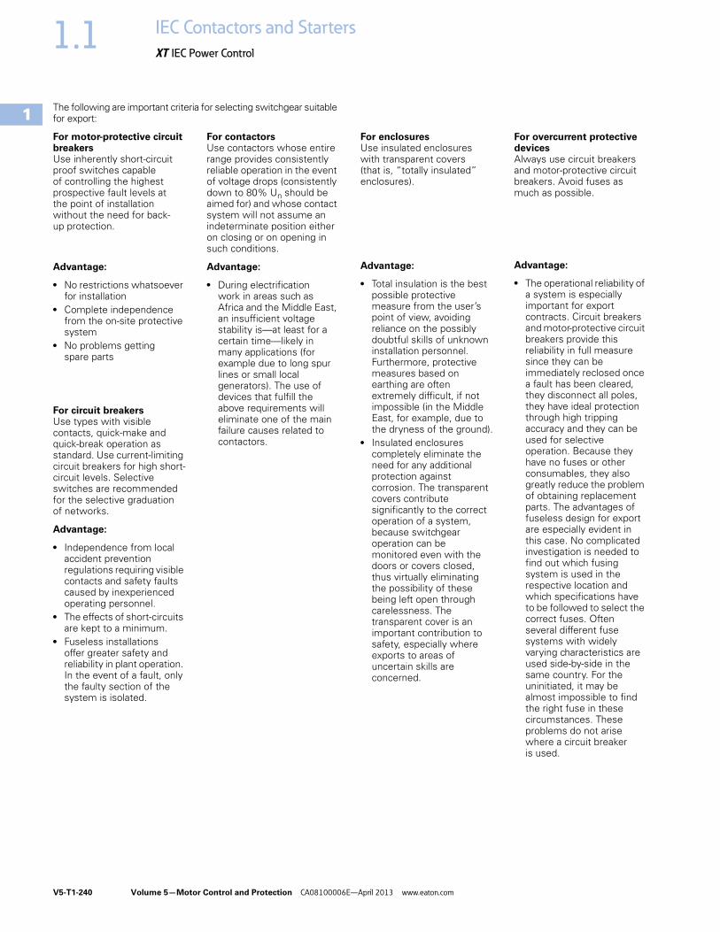
V5-T1-240 Volume 5—Motor Control and Protection CA08100006E—April 2013 www.eaton.com
1
1
1
1
1
1
1
1
1
1
1
1
1
1
1
1
1
1
1
1
1
1
1
1
1
1
1
1
1
1
1.1 IEC Contactors and Starters
XT IEC Power Control
The following are important criteria for selecting switchgear suitable for export:
For motor-protective circuit breakersUse inherently short-circuit proof switches capable of controlling the highest prospective fault levels at the point of installation without the need for back-up protection.
Advantage:
● No restrictions whatsoever for installation
● Complete independence from the on-site protective system
● No problems getting spare parts
For circuit breakersUse types with visible contacts, quick-make and quick-break operation as standard. Use current-limiting circuit breakers for high short-circuit levels. Selective switches are recommended for the selective graduation of networks.
Advantage:
● Independence from local accident prevention regulations requiring visible contacts and safety faults caused by inexperienced operating personnel.
● The effects of short-circuits are kept to a minimum.
● Fuseless installations offer greater safety and reliability in plant operation. In the event of a fault, only the faulty section of the system is isolated.
For contactorsUse contactors whose entire range provides consistently reliable operation in the event of voltage drops (consistently down to 80% Un should be aimed for) and whose contact system will not assume an indeterminate position either on closing or on opening in such conditions.
Advantage:
● During electrification work in areas such as Africa and the Middle East, an insufficient voltage stability is—at least for a certain time—likely in many applications (for example due to long spur lines or small local generators). The use of devices that fulfill the above requirements will eliminate one of the main failure causes related to contactors.
For enclosuresUse insulated enclosures with transparent covers (that is, “totally insulated” enclosures).
Advantage:
● Total insulation is the best possible protective measure from the user’s point of view, avoiding reliance on the possibly doubtful skills of unknown installation personnel. Furthermore, protective measures based on earthing are often extremely difficult, if not impossible (in the Middle East, for example, due to the dryness of the ground).
● Insulated enclosures completely eliminate the need for any additional protection against corrosion. The transparent covers contribute significantly to the correct operation of a system, because switchgear operation can be monitored even with the doors or covers closed, thus virtually eliminating the possibility of these being left open through carelessness. The transparent cover is an important contribution to safety, especially where exports to areas of uncertain skills are concerned.
For overcurrent protective devicesAlways use circuit breakers and motor-protective circuit breakers. Avoid fuses as much as possible.
Advantage:
● The operational reliability of a system is especially important for export contracts. Circuit breakers and motor-protective circuit breakers provide this reliability in full measure since they can be immediately reclosed once a fault has been cleared, they disconnect all poles, they have ideal protection through high tripping accuracy and they can be used for selective operation. Because they have no fuses or other consumables, they also greatly reduce the problem of obtaining replacement parts. The advantages of fuseless design for export are especially evident in this case. No complicated investigation is needed to find out which fusing system is used in the respective location and which specifications have to be followed to select the correct fuses. Often several different fuse systems with widely varying characteristics are used side-by-side in the same country. For the uninitiated, it may be almost impossible to find the right fuse in these circumstances. These problems do not arise where a circuit breaker is used.
Volume 5—Motor Control and Protection CA08100006E—April 2013 www.eaton.com V5-T1-241
1
1
1
1
1
1
1
1
1
1
1
1
1
1
1
1
1
1
1
1
1
1
1
1
1
1
1
1
1
1
1.1IEC Contactors and Starters
XT IEC Power Control
For main switches and safety switchesUse devices with positive contact separation and clear switch position indication.
Advantage:
● The mechanical coupling of the actuating element with the contacts ensues that the OFF position is indicated only when all main contacts are separated by the prescribed distance and only in this position can the switch be padlocked. This ensures safety when carrying out maintenance and repair work on the installation or machinery.
Test Authorities
Approvals for North AmericaIn the U.S., the legally established OSHA (Occupational Safety and Health Act) and the NEC (National Electrical Code) require the use of approved devices and systems.
In Canada, all electrical apparatus must comply with the CEC (Canadian Electrical Code), which requires that all equipment and installations have CSA approval.
In addition to the normal UL and CSA approvals, the trade regulations originating from the NAFTA agreements allow the application for a joint UL and CSA approval. The devices then carry a logo that is recognized in both countries.
Some local inspectors and end users still refuse to accept the joint listing.
USAUSAUL
CanadaCDNCSA
RomaniaROICECONRussiaRUSGOST-RSouth AfricaZASABSSlovakiaSKSKTC
PolandPLBBJ-SEP
TurkeyTRTSEChinaPRCCCC
UkraineUAUkrain-GOST
Shipping Classifications
Approvals for North America
GermanyGermanischer Lloyd (GL)
Great BritainLloyd‘s Register of Shipping (LR)
FranceBureau Veritas (BV)
RussiaRussian Maritime Register of Shipping (RS)
ItalyRegistro Italiano Navale (RINA)
NorwayDet Norske Veritas(DNV)
PolandPolski Rejestr Statkow (PRS)
Type of Approval Approval Mark
The device is UL- and CSA-approved as discrete device.
The device is CSA-approved as discrete device.
The device is UL-approved as discrete device.
The device contains UL-approved components; its approval conditions must be maintained in use (UL Recognized). The device is CSA-approved as discrete device.

V5-T1-242 Volume 5—Motor Control and Protection CA08100006E—April 2013 www.eaton.com
1
1
1
1
1
1
1
1
1
1
1
1
1
1
1
1
1
1
1
1
1
1
1
1
1
1
1
1
1
1
1.1 IEC Contactors and Starters
XT IEC Power Control
IEC Utilization Categories(See also IEC/EN 60947-1; 2.1.18/IEV 441-17-19)
A combination of specified requirements relating to the condition in which the switching device or fuse fulfills its purpose and selected to represent a characteristic group of real-life applications. The specified requirements may,
for example, relate to the values of making and breaking capacity and other characteristic values, data concerning associated circuits and the applicable conditions of use and operational behavior.
Used in Technical Data and Formula
Code Description
DF Duty factory
IDn Response value of earth-fault release
Icm Rated short-circuit making capacity
Icn Rated short-circuit breaking capacity
Ics Rated service short-circuit breaking capacity
Icu Rated ultimate short-circuit breaking capacity
Icw Rated short-time withstand current
Ie Rated operational current
Ik Transformer initial short-circuit AC current
IL Load monitoring response value
In Rated current
INT Transformer rated current
IPK Rated peak withstand current
Iq Rated conditional short-circuit current
Ir Overcurrent release set value
Irm Response value of non-delayed short-circuit release
Ii Response value of non-delayed short-circuit release
Irmf Response value of fixed, non-delayed short-circuit release
Code Description
Irmv Response value of short-time delayed short-circuit release
Isd Response value of short-time delayed short-circuit release
IT Response value of earth-fault release
Ig Response value of earth-fault release
Ith Conventional free air thermal current
Ithe Conventional thermal current of enclosed devices
Iu Rated uninterrupted current
SNT Transformer rating
tr Time delay of overload release response
tT Time delay of earth-fault release response
tg Time delay of earth-fault release response
tv Time delay of short-circuit release response
Uc Rated actuating voltage
Ue Rated operational voltage
Ui Rated insulation voltage
Uimp Rated impulse withstand voltage
Uk Transformer short-circuit voltage
Us Rated control voltage

Volume 5—Motor Control and Protection CA08100006E—April 2013 www.eaton.com V5-T1-243
1
1
1
1
1
1
1
1
1
1
1
1
1
1
1
1
1
1
1
1
1
1
1
1
1
1
1
1
1
1
1.1IEC Contactors and Starters
XT IEC Power Control
Annex A (informative)
Examples of Utilization Categories for Low Voltage Switchgear and Controlgear 1
Notes1 60947-1 © IEC: 2004.2 Plugging is stopping or reversing the motor rapidly by reversing motor primary connections while the motor is running.3 Inching (jogging) is energizing a motor once or repeatedly for short periods to obtain small movements of the driven mechanism.
Category Typical Application Relevant IEC Product Standard
Nature of Current—AC
AC-1 Non-inductive or slightly inductive loads, resistance furnaces 60947-4-1
AC-2 Slip-ring motors: starting, switching off 60947-4-1
AC-3 Squirrel cage motors: starting, switching off motors during running 60947-4-1
AC-4 Squirrel cage motors: starting, plugging 2, inching 3 60947-4-1
AC-5a Switching of electric discharge lamp controls 60947-4-1
AC-5b Switching of incandescent lamps 60947-4-1
AC-6a Switching of transformers 60947-4-1
AC-6b Switching of capacitor banks 60947-4-1
AC-7a Slightly inductive loads for household appliances and similar applications 61095
AC-7b Motor-loads for household applications 61095
AC-8a Hermetic refrigerant compressor motor control with manual resetting of overload releases 60947-4-1
AC-8b Hermetic refrigerant compressor motor control with automatic resetting of overload releases 60947-4-1
AC-12 Control of resistive loads and solid-state loads with isolation by optocouplers 60947-5-1
AC-12 Control of resistive loads and solid-state loads with optical isolation 60947-5-2
AC-13 Control of solid-state loads with transformer isolation 60947-5-1
AC-14 Control of small electromagnetic loads 60947-5-1
AC-15 Control of AC electromagnetic loads 60947-5-1
AC-20 Connecting and disconnecting under no-load conditions 60947-3
AC-21 Switching of resistive loads, including moderate overloads 60947-3
AC-22 Switching of mixed resistive and inductive loads, including moderate overloads 60947-3
AC-23 Switching of motor loads or other highly inductive loads 60947-3
AC-31 Non-inductive or slightly inductive loads 60947-6-1
AC-33 Motor loads or mixed loads including motors, resistive loads and up to 30% incandescent lamp loads 60947-6-1
AC-35 Electric discharge lamp loads 60947-6-1
AC-36 Incandescent lamp loads 60947-6-1
AC-40 Distribution circuits comprising mixed resistive and reactive loads having a resultant inductive reactance 60947-6-2
AC-41 Non-inductive or slightly inductive loads, resistance furnaces 60947-6-2
AC-42 Slip-ring motors: starting, switching off 60947-6-2
AC-43 Squirrel cage motors: starting, switching off motors during running 60947-6-2
AC-44 Squirrel cage motors: starting, plugging 2, inching 3 60947-6-2
AC-45a Switching of electric discharge lamp controls 60947-6-2
AC-45b Switching of incandescent lamps 60947-6-2
AC-51 Non-inductive or slightly inductive loads, resistance furnaces 60947-4-3
AC-52a Control of slip ring motor stators: 8 h duty with on-load currents for start, acceleration, run 60947-4-2
AC-52b Control of slip ring motor stators: intermittent duty 60947-4-2
AC-53a Control of squirrel cage motors: 8 h duty with on-load currents for start, acceleration, run 60947-4-2
AC-53b Control of squirrel cage motors: intermittent duty 60947-4-2
AC-55a Switching of electric discharge lamp controls 60947-4-3
AC-55b Switching of incandescent lamps 60947-4-3
AC-56a Switching of transformers 60947-4-3
AC-56b Switching of capacitor banks 60947-4-3

V5-T1-244 Volume 5—Motor Control and Protection CA08100006E—April 2013 www.eaton.com
1
1
1
1
1
1
1
1
1
1
1
1
1
1
1
1
1
1
1
1
1
1
1
1
1
1
1
1
1
1
1.1 IEC Contactors and Starters
XT IEC Power Control
Examples of Utilization Categories for Low-Voltage Switchgear and Controlgear, continued 1
Notes1 60947-1 © IEC: 2004.2 Plugging is stopping or reversing the motor rapidly by reversing motor primary connections while the motor is running.3 Inching (jogging) is energizing a motor once or repeatedly for short periods to obtain small movements of the driven mechanism.
Category Typical Application Relevant IEC Product Standard
Nature of Current—AC, continued
AC-58a Control of hermetic refrigerant compressor motors with automatic resetting of overload releases: h duty with on-load currents for start, acceleration, run
60947-4-2
AC-58b Control of hermetic refrigerant compressor motors with automatic resetting of overload releases: intermittent duty 60947-4-2
AC-140 Control of small electromagnetic loads with holding (closed) current <0,2 A, for example, contactor relays 60947-5-2
Nature of Current—AC and DC
A Protection of circuits, with no rated short-time withstand current 60947-2
B Protection of circuits, with a rated short-time withstand current 60947-2
Nature of Current—DC
DC-1 Non-inductive or slightly inductive loads, resistance furnaces 60947-4-1
DC-3 Shunt-motors: starting, plugging 2, inching 3, dynamic breaking of motors 60947-4-1
DC-5 Series-motors: starting, plugging 2, inching 3, dynamic breaking of motors 60947-4-1
DC-6 Switching of incandescent lamps 60947-4-1
DC-12 Control of resistive loads and solid-state loads with isolation by optocouplers 60947-5-1
DC-12 Control of resistive loads and solid-state loads with optical isolation 60947-5-2
DC-13 Control of electromagnets 60947-5-1
DC-13 Control of electromagnets 60947-5-2
DC-14 Control of electromagnetic loads having economy resistors in circuit 60947-5-1
DC-20 Connecting and disconnecting under no-load conditions 60947-3
DC-21 Switching of resistive loads, including moderate overloads 60947-3
DC-22 Switching of mixed resistive and inductive loads, including moderate overloads (for example, shunt motors) 60947-3
DC-23 Switching of motor loads or other highly inductive loads (for example, series motors) 60947-3
DC-31 Resistive loads 60947-6-1
DC-33 Motor loads or mixed loads including motors 60947-6-1
DC-36 Incandescent lamp loads 60947-6-1
DC-40 Distribution circuits comprising mixed resistive and reactive loads having a resultant inductive reactance 60947-6-2
DC-41 Non-inductive or slightly inductive loads, resistance furnaces 60947-6-2
DC-43 Shunt-motors: starting, plugging 2, inching 3, dynamic breaking of DC 60947-6-2
DC-45 Series-motors: starting, plugging 2, inching 3, dynamic breaking of DC 60947-6-2
DC-46 Switching of incandescent lamps 60947-6-2

Volume 5—Motor Control and Protection CA08100006E—April 2013 www.eaton.com V5-T1-245
1
1
1
1
1
1
1
1
1
1
1
1
1
1
1
1
1
1
1
1
1
1
1
1
1
1
1
1
1
1
1.1IEC Contactors and Starters
XT IEC Power Control
Motor Ratings Data
Ampere Rating of AC and DC MotorsAmpere ratings of motors vary somewhat, depending upon the type of motor. The values given below are for drip-proof, Class B insulated (T Frame) where available, 1.15 service factor, NEMA Design B motors. These values represent an average full load motor current that was calculated from the motor performance data published by several motor manufacturers. In the case of high torque squirrel cage motors, the ampere ratings will be at least 10% greater than the values given below.
Caution—These average ratings could be high or low for a specific motorand therefore heater coil selection on this basis always involves risk. For fully reliable motor protection, select heater coils on the basis of full load current rating as shown on the motor nameplate.
Ampere Ratings of Three-Phase, 60 Hz, AC Induction Motor
Note1 380V 50 Hz.
hp
Syn.SpeedRPM
Current in Amperes
200V 230V 380V 1 460V 575V
1/4 1800 1.09 0.95 0.55 0.48 0.38
1200 1.61 1.40 0.81 0.70 0.56
900 1.84 1.60 0.93 0.80 0.64
1/3 1800 1.37 1.19 0.69 0.60 0.48
1200 1.83 1.59 0.92 0.80 0.64
900 2.07 1.80 1.04 0.90 0.72
1/2 1800 1.98 1.72 0.99 0.86 0.69
1200 2.47 2.15 1.24 1.08 0.86
900 2.74 2.38 1.38 1.19 0.95
3/4 1800 2.83 2.46 1.42 1.23 0.98
1200 3.36 2.92 1.69 1.46 1.17
900 3.75 3.26 1.88 1.63 1.30
1 3600 3.22 2.80 1.70 1.40 1.12
1800 4.09 3.56 2.06 1.78 1.42
1200 4.32 3.76 2.28 1.88 1.50
900 4.95 4.30 2.60 2.15 1.72
1-1/2 3600 5.01 4.36 2.64 2.18 1.74
1800 5.59 4.86 2.94 2.43 1.94
1200 6.07 5.28 3.20 2.64 2.11
900 6.44 5.60 3.39 2.80 2.24
2 3600 6.44 5.60 3.39 2.80 2.24
1800 7.36 6.40 3.87 3.20 2.56
1200 7.87 6.84 4.14 3.42 2.74
900 9.09 7.90 4.77 3.95 3.16
3 3600 9.59 8.34 5.02 4.17 3.34
1800 10.8 9.40 5.70 4.70 3.76
1200 11.7 10.2 6.20 5.12 4.10
900 13.1 11.4 6.90 5.70 4.55
5 3600 15.5 13.5 8.20 6.76 5.41
1800 16.6 14.4 8.74 7.21 5.78
1200 18.2 15.8 9.59 7.91 6.32
900 18.3 15.9 9.60 7.92 6.33
7-1/2 3600 22.4 19.5 11.8 9.79 7.81
1800 24.7 21.5 13.0 10.7 8.55
1200 25.1 21.8 13.2 10.9 8.70
900 26.5 23.0 13.9 11.5 9.19
10 3600 29.2 25.4 15.4 12.7 10.1
1800 30.8 26.8 16.3 13.4 10.7
1200 32.2 28.0 16.9 14.0 11.2
900 35.1 30.5 18.5 15.2 12.2

V5-T1-246 Volume 5—Motor Control and Protection CA08100006E—April 2013 www.eaton.com
1
1
1
1
1
1
1
1
1
1
1
1
1
1
1
1
1
1
1
1
1
1
1
1
1
1
1
1
1
1
1.1 IEC Contactors and Starters
XT IEC Power Control
Ampere Ratings of Three-Phase, 60 Hz, AC Induction Motor, continued
Single-Phase AC MotorsThe following values of full-load currents are for motors running at usual speeds and motors with normal torque characteristics. Motors built for especially low speeds or high torques may have higher full-load currents and multispeed motors will have full-load current varying with speed, in which case the nameplate current ratings shall be used.
The voltages listed are rated motor voltages. The currents listed shall be permitted for system voltage ranges of 110 to 120 and 220 to 240V.
hp
Syn.SpeedRPM
Current in Amperes200V 230V 380V 1 460V 575V
15 3600 41.9 36.4 22.0 18.2 14.5
1800 45.1 39.2 23.7 19.6 15.7
1200 47.6 41.4 25.0 20.7 16.5
900 51.2 44.5 26.9 22.2 17.8
20 3600 58.0 50.4 30.5 25.2 20.1
1800 58.9 51.2 31.0 25.6 20.5
1200 60.7 52.8 31.9 26.4 21.1
900 63.1 54.9 33.2 27.4 21.9
25 3600 69.9 60.8 36.8 30.4 24.3
1800 74.5 64.8 39.2 32.4 25.9
1200 75.4 65.6 39.6 32.8 26.2
900 77.4 67.3 40.7 33.7 27.0
30 3600 84.8 73.7 44.4 36.8 29.4
1800 86.9 75.6 45.7 37.8 30.2
1200 90.6 78.8 47.6 39.4 31.5
900 94.1 81.8 49.5 40.9 32.7
40 3600 111 96.4 58.2 48.2 38.5
1800 116 101 61.0 50.4 40.3
1200 117 102 61.2 50.6 40.4
900 121 105 63.2 52.2 41.7
50 3600 138 120 72.9 60.1 48.2
1800 143 124 75.2 62.2 49.7
1200 145 126 76.2 63.0 50.4
900 150 130 78.5 65.0 52.0
60 3600 164 143 86.8 71.7 57.3
1800 171 140 90.0 74.5 59.4
1200 173 150 91.0 75.0 60.0
900 177 154 93.1 77.0 61.5
Full-Load Currents in Amperes, Single-Phase Alternating-Current Motor
Note1 380V 50 Hz.
hp
Syn.SpeedRPM
Current in Amperes200V 230V 380V 1 460V 575V
75 3600 206 179 108 89.6 71.7
1800 210 183 111 91.6 73.2
1200 212 184 112 92.0 73.5
900 222 193 117 96.5 77.5
100 3600 266 231 140 115 92.2
1800 271 236 144 118 94.8
1200 275 239 145 120 95.6
900 290 252 153 126 101
125 3600 — 292 176 146 116
1800 — 293 177 147 117
1200 — 298 180 149 119
900 — 305 186 153 122
150 3600 — 343 208 171 137
1800 — 348 210 174 139
1200 — 350 210 174 139
900 — 365 211 183 146
200 3600 — 452 257 226 181
1800 — 458 265 229 184
1200 — 460 266 230 184
900 — 482 279 241 193
250 3600 — 559 338 279 223
1800 — 568 343 284 227
1200 — 573 345 287 229
900 — 600 347 300 240
300 1800 — 678 392 339 271
1200 — 684 395 342 274
400 1800 — 896 518 448 358
500 1800 — 1110 642 555 444
hp 115V 200V 208V 230V
1/6 4.4 2.5 2.4 2.2
1/4 5.8 3.3 3.2 2.9
1/3 7.2 4.1 4.0 3.6
1/2 9.8 5.6 5.4 4.9
3/4 13.8 7.9 7.6 6.9
1 16 9.2 8.8 8
1-1/2 20 11.5 11 10
2 24 13.8 13.2 12
3 34 19.6 18.7 17
5 56 32.2 30.8 28
7-1/2 80 46 44 40
10 100 57.5 55 50

Volume 5—Motor Control and Protection CA08100006E—April 2013 www.eaton.com V5-T1-247
1
1
1
1
1
1
1
1
1
1
1
1
1
1
1
1
1
1
1
1
1
1
1
1
1
1
1
1
1
1
1.1IEC Contactors and Starters
XT IEC Power Control
Three-Phase AC MotorsThe following values of full-load currents are typical for motors running at speeds usual for belted motors and motors with normal torque characteristics.
Motors built for low speeds (1,200 RPM or less) or high torques may require more running current and multi-speed motors will have full-load current varying with speed. In these cases the nameplate current rating shall be used.
The voltages listed are rated motor voltages. The currents listed shall be permitted for system voltage ranges of 110 to 120, 220 to 240, 440 to 480 and 550 to 600V.
Full-Load Current Three-Phase Alternating-Current Motors
Note1 For 90 and 80 percent power factor, the above figures shall be multiplied by 1.1 and 1.25 respectively.
hpInduction Type Squirrel Cage and Wound-Rotor Amperes Synchronous Type Unity Power Factor 1 Amperes115V 200V 208V 230V 460V 575V 230V 460V 575V
1/2 4.4 2.5 2.4 2.2 1.1 .9 — — —
3/4 6.4 3.7 3.5 3.2 1.6 1.3 — — —
1 8.4 4.8 4.6 4.2 2.1 1.7 — — —
1-1/2 12.0 6.9 6.6 6.0 3.0 2.4 — — —
2 13.6 7.8 7.5 6.8 3.4 2.7 — — —
3 — 11.0 10.6 9.6 4.8 3.9 — — —
5 — 17.5 16.7 15.2 7.6 6.1 — — —
7-1/2 — 25.3 24.2 22 11 9 — — —
10 — 32.2 30.8 28 14 11 — — —
15 — 48.3 46.2 42 21 17 — — —
20 — 62.1 59.4 54 27 22 — —
25 — 78.2 74.8 68 34 27 53 26 21
30 — 92 88 80 40 32 63 32 26
40 — 120 114 104 52 41 83 41 33
50 — 150 143 130 65 52 104 52 42
60 — 177 169 154 77 62 123 61 49
75 — 221 211 192 96 77 155 78 62
100 — 285 273 248 124 99 202 101 81
125 — 359 343 312 156 125 253 126 101
150 — 414 396 360 180 144 302 151 121
200 — 552 528 480 240 192 400 201 161
250 — — — — 302 242 — — —
300 — — — — 361 289 — — —
350 — — — — 414 336 — — —
400 — — — — 477 382 — — —
450 — — — — 515 412 — — —
500 — — — — 590 472 — — —

V5-T1-248 Volume 5—Motor Control and Protection CA08100006E—April 2013 www.eaton.com
1
1
1
1
1
1
1
1
1
1
1
1
1
1
1
1
1
1
1
1
1
1
1
1
1
1
1
1
1
1
1.1 IEC Contactors and Starters
XT IEC Power Control
DC MotorsThe following values of full-load currents are for motors running at base speed.
Full-Load Current in Amperes, Direct-Current Motors
Note1 These are average direct-current quantities.
hpArmature Voltage Rating 1
Ampere Capacity of Fuses for MotorsRecommended Values
120V 240V 120V 240V
1/4 3.1 1.6 5 3
1/3 4.1 2.0 5 3
1/2 5.4 2.7 7 3
3/4 7.6 3.8 10 5
1 9.5 4.7 15 7
1-1/2 13.2 6.6 20 10
2 17 8.5 25 12
3 25 12.2 30 15
5 40 20 50 25
7-1/2 58 29 80 40
10 76 38 100 50
15 — 55 — 75
20 — 72 — 100
25 — 89 — 125
30 — 106 — 150
40 — 140 — 200
50 — 173 — 250
60 — 206 — 275
75 — 255 — 350
100 — 341 — 500
125 — 425 — 600
150 — 506 — —
200 — 675 — —

Volume 5—Motor Control and Protection CA08100006E—April 2013 www.eaton.com V5-T1-249
1
1
1
1
1
1
1
1
1
1
1
1
1
1
1
1
1
1
1
1
1
1
1
1
1
1
1
1
1
1
1.1IEC Contactors and Starters
XT IEC Power Control
Ampacities of Insulated Conductors (Based on 2005 NEC)
Table 310.16. Allowable Ampacities of Insulated Conductors Rated 0–2000V, 60°–90°C [140°–194°F], Not More Than Three Current-Carrying Conductors in Raceway or Cable or Earth (Directly Buried), Based on Ambient Temperature of 30°C [86°F] 1
Notes1 Reprinted by permission from NFPA 70-2005. National Electrical Code®, Copyright© 2005. National Fire Protection Association, Batterymarch Park, Quincy, MA 02269. 2 Unless otherwise specifically permitted elsewhere in this Code, the overcurrent protection for conductor types marked with an obelisk (†) shall not exceed 15A for No. 14, 20A for No. 12 and 30A
for No. 10 copper; or 15A for No. 12 and 25A for No. 10 aluminum and copper-clad aluminum after any correction factors for ambient temperature and number of conductors have been applied.
Size
AWGkcmil
Temperature Rating of Conductor. See NEC Table 310-13.
Size
AWGkcmil
Copper Aluminum or Copper-Clad Aluminum60°C [140°F] 75°C [167°F] 90°C [194°F] 60°C [140°F] 75°C [167°F] 90°C [194°F]
TypesTW†, UF 2
Types FEPW 2, RH 2, RHW 2, THHW 2, THW 2, THWN 2, XHHW 2, USE 2, ZW 2
TypesTBS, SA, SIS, FEP 2, FEPB 2, MI,RHH 2, RHW-2, THHN 2, THHW 2,THW-2 2, THWN-2 2, USE-2, XHH, XHHW 2, XHHW-2, ZW-2
TypesTW 2, UF 2
Types RH 2, RHW 2, THHW 2, THW 2, THWN 2, XHHW 2, USE 2
TypesTBS, SA, SIS, THHN 2, THHW 2, THW-2, THWN-2, RHH 2, RHW-2, USE-2, XHH, XHHW, XHHW-2, ZW-2
18 — — 14 — — — —
16 — — 18 — — — —
14 20✝ 20✝ 25† — — — —
12 25✝ 25✝ 30† 20† 20† 25† 12
10 30 35✝ 40† 25 30† 35† 10
8 40 50 55 30 40 45 8
6 55 65 75 40 50 60 6
70 85 95 55 65 75 4 70
85 100 110 65 75 85 3 85
95 115 130 75 90 100 2 95
110 130 150 85 100 115 1 110
1/0 125 150 170 100 120 135 1/0
2/0 145 175 195 115 135 150 2/0
3/0 165 200 225 130 155 175 3/0
4/0 195 230 260 150 180 205 4/0
250 215 255 290 170 205 230 250
300 240 285 320 190 230 255 300
350 260 310 350 210 250 280 350
400 280 335 380 225 270 305 400
500 320 380 430 260 310 350 500
600 355 420 475 285 340 385 600
700 385 460 520 310 375 420 700
750 400 475 535 320 385 435 750
800 410 490 555 330 395 450 800
600 355 420 475 285 340 385 600
700 385 460 520 310 375 420 700
750 400 475 535 320 385 435 750
800 410 490 555 330 395 450 800
900 435 520 585 355 425 480 900
1000 455 545 615 375 445 500 1000
1250 495 590 665 405 485 545 1250
1500 520 625 705 435 520 585 1500
1750 545 650 735 455 545 615 1750
2000 560 665 750 470 560 630 2000

V5-T1-250 Volume 5—Motor Control and Protection CA08100006E—April 2013 www.eaton.com
1
1
1
1
1
1
1
1
1
1
1
1
1
1
1
1
1
1
1
1
1
1
1
1
1
1
1
1
1
1
1.1 IEC Contactors and Starters
XT IEC Power Control
Table 310.16. Allowable Ampacities of Insulated Conductors Rated 0–2000V, 60°–90°C [140°–194°F], Not More Than Three Current-Carrying Conductors in Raceway or Cable or Earth (Directly Buried), Based on Ambient Temperature of 30°C [86°F]—Correction Factors 1
Where the number of current-carrying conductors in a raceway or cable exceeds three, the allowable ampacities shall be reduced as shown in the following table:
Table 310.15 (B)(2)(a). Adjustment Factor for More Than Three Current-Carrying Conductors in Raceway or Cable
Where single conductors or multiconductor cables are stacked or bundled longer than 24 in (610 mm) without maintaining spacing and are not installed in raceways, the allowable ampacity of each conductor shall be reduced as shown in the above table.
Notes1 Reprinted by permission from NFPA 70-2005. National Electrical Code®, Copyright© 2005.
National Fire Protection Association, Batterymarch Park, Quincy, MA 02269. 2 Unless otherwise specifically permitted elsewhere in this Code, the overcurrent protection
for conductor types marked with an obelisk (†) shall not exceed 15A for No. 14, 20A for No. 12 and 30A for No. 10 copper; or 15A for No. 12 and 25A for No. 10 aluminum and copper-clad aluminum after any correction factors for ambient temperature and number of conductors have been applied.
Temperature Rating of Conductor. See NEC Table 310-13.
Size
AWGkcmil
Copper Aluminum or Copper-Clad Aluminum
Size
AWGkcmil
60°C [140°F] 75°C [167°F] 90°C [194°F] 60°C [140°F] 75°C [167°F] 90°C [194°F]
TypesTW†, UF 2
Types FEPW 2, RH 2, RHW 2, THHW 2, THW 2, THWN 2, XHHW 2, USE 2, ZW 2
TypesTBS, SA, SIS, FEP 2, FEPB 2, MI,RHH 2, RHW-2, THHN 2, THHW 2,THW-2 2, THWN-2 2, USE-2, XHH, XHHW 2, XHHW-2, ZW-2
TypesTW 2, UF 2
Types RH 2, RHW 2, THHW 2, THW 2, THWN 2, XHHW 2, USE 2
TypesTBS, SA, SIS, THHN 2, THHW 2, THW-2, THWN-2, RHH 2, RHW-2, USE-2, XHH, XHHW, XHHW-2, ZW-2
AmbientTemp. °C
For Ambient Temperatures Other Than 30°C [86°F], Multiply the Allowable Ampacities Shown in the Table on Page V5-T1-249 by the Appropriate Factor Shown Below
For Ambient Temperatures Other Than 30°C [86°F], Multiply the Allowable Ampacities Shown in the Table on Page V5-T1-249 by the Appropriate Factor Shown Below
Ambient Temp. °F
21–25 1.08 1.05 1.04 1.08 1.05 1.04 70–77
26–30 1.00 1.00 1.00 1.00 1.00 1.00 78–86
31–35 0.91 0.94 0.96 0.91 0.94 0.96 87–95
36–40 0.82 0.88 0.91 0.82 0.88 0.91 96–104
41–45 0.71 0.82 0.87 0.71 0.82 0.87 105–113
46–50 0.58 0.75 0.82 0.58 0.75 0.82 114–122
51–55 0.41 0.67 0.76 0.41 0.67 0.76 123–131
56–60 — 0.58 0.71 — 0.58 0.71 132–140
61–70 — 0.33 0.58 — 0.33 0.58 141–158
71–80 — — 0.41 — — 0.41 159–176
Number of Current-Carrying Conductors
Percent of Values in Tables as Adjustedfor Ambient Temperature if Necessary
4–6 80
7–9 70
10–20 50
21–30 45
31–40 40
41 and above 35
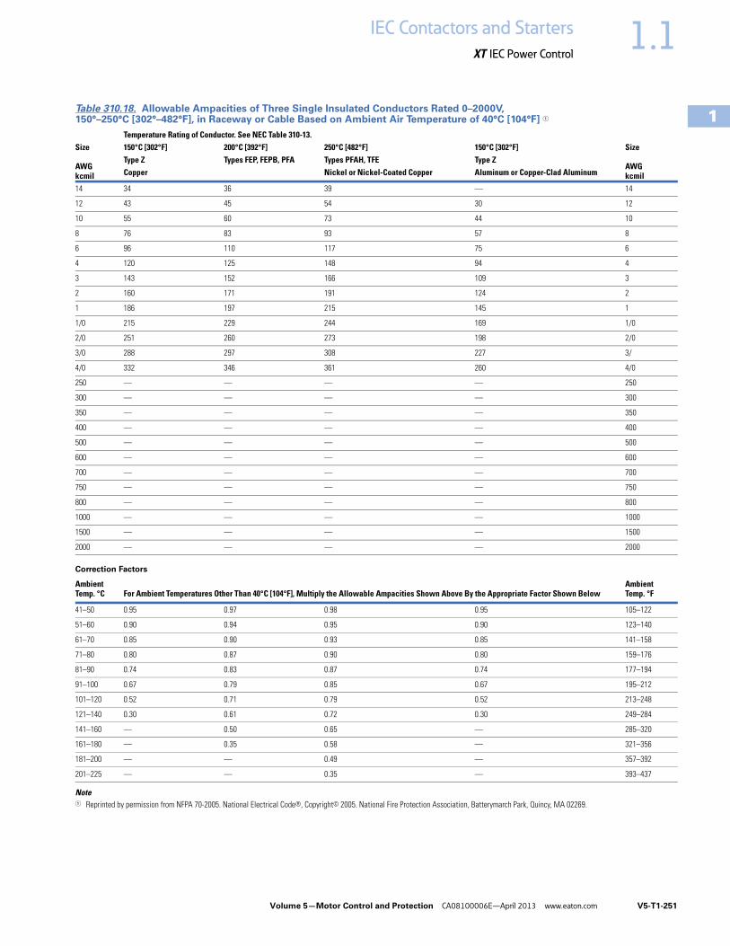
Volume 5—Motor Control and Protection CA08100006E—April 2013 www.eaton.com V5-T1-251
1
1
1
1
1
1
1
1
1
1
1
1
1
1
1
1
1
1
1
1
1
1
1
1
1
1
1
1
1
1
1.1IEC Contactors and Starters
XT IEC Power Control
Table 310.18. Allowable Ampacities of Three Single Insulated Conductors Rated 0–2000V, 150°–250°C [302°–482°F], in Raceway or Cable Based on Ambient Air Temperature of 40°C [104°F] 1
Note1 Reprinted by permission from NFPA 70-2005. National Electrical Code®, Copyright© 2005. National Fire Protection Association, Batterymarch Park, Quincy, MA 02269.
Size
AWGkcmil
Temperature Rating of Conductor. See NEC Table 310-13.Size
AWGkcmil
150°C [302°F] 200°C [392°F] 250°C [482°F] 150°C [302°F]Type Z Types FEP, FEPB, PFA Types PFAH, TFE Type ZCopper Nickel or Nickel-Coated Copper Aluminum or Copper-Clad Aluminum
14 34 36 39 — 14
12 43 45 54 30 12
10 55 60 73 44 10
8 76 83 93 57 8
6 96 110 117 75 6
4 120 125 148 94 4
3 143 152 166 109 3
2 160 171 191 124 2
1 186 197 215 145 1
1/0 215 229 244 169 1/0
2/0 251 260 273 198 2/0
3/0 288 297 308 227 3/
4/0 332 346 361 260 4/0
250 — — — — 250
300 — — — — 300
350 — — — — 350
400 — — — — 400
500 — — — — 500
600 — — — — 600
700 — — — — 700
750 — — — — 750
800 — — — — 800
1000 — — — — 1000
1500 — — — — 1500
2000 — — — — 2000
Correction Factors
AmbientTemp. °C For Ambient Temperatures Other Than 40°C [104°F], Multiply the Allowable Ampacities Shown Above By the Appropriate Factor Shown Below
AmbientTemp. °F
41–50 0.95 0.97 0.98 0.95 105–122
51–60 0.90 0.94 0.95 0.90 123–140
61–70 0.85 0.90 0.93 0.85 141–158
71–80 0.80 0.87 0.90 0.80 159–176
81–90 0.74 0.83 0.87 0.74 177–194
91–100 0.67 0.79 0.85 0.67 195–212
101–120 0.52 0.71 0.79 0.52 213–248
121–140 0.30 0.61 0.72 0.30 249–284
141–160 — 0.50 0.65 — 285–320
161–180 — 0.35 0.58 — 321–356
181–200 — — 0.49 — 357–392
201–225 — — 0.35 — 393–437