iec power control combination starters & starters for … industry, inc. 4/1 industrial controls...
TRANSCRIPT
4/1Siemens Industry, Inc.Industrial Controls Catalog
Contents
Siemens / Industrial Controls Previous folio: 4/1
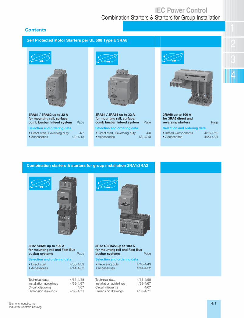
Self Protected Motor Starters per UL 508 Type E 3RA6
Combination starters & starters for group installation 3RA1/3RA2
IEC Power ControlCombination Starters & Starters for Group Installation
3RA61 / 3RA62 up to 32 Afor mounting rail, surface,comb busbar, infeed system Page
Selection and ordering data
• Direct start, Reversing duty 4/7• Accessories 4/9-4/13
3RA1/3RA2 up to 100 A for mounting rail and Fast Bus busbar systems Page
Selection and ordering data
• Direct start 4/36-4/39• Accessories 4/44-4/52
Technical data 4/53-4/58Installation guidelines 4/59-4/67Circuit diagrams 4/67Dimension drawings 4/68-4/71
3RA11/3RA22 up to 100 A for mounting rail and Fast Bus busbar systems Page
Selection and ordering data
• Reversing duty 4/40-4/43• Accessories 4/44-4/52
Technical data 4/53-4/58Installation guidelines 4/59-4/67Circuit diagrams 4/67Dimension drawings 4/68-4/71
3RA64 / 3RA65 up to 32 A for mounting rail, surface, comb busbar, infeed system Page
Selection and ordering data
• Direct start, Reversing duty 4/8• Accessories 4/9-4/13
3RA68 up to 100 A for 3RA6 direct and reversing starters Page
Selection and ordering data
• Infeed Components 4/16-4/19• Accessories 4/20-4/21
4/2 Siemens Industry, Inc.Industrial Controls Catalog
SIRIUS
Siemens / Industrial Controls Previous folio: LV1 6/57
Compact Combination StartersSIRIUS 3RA6 Compact Starters
General data
For Operation in the Control CabinetSIRIUS 3RA6 Compact Starters
General data
6/32 SIRIUS Innovations Supplement 2012
6
Overview
3RA6 compact starters and infeed system for 3RA6
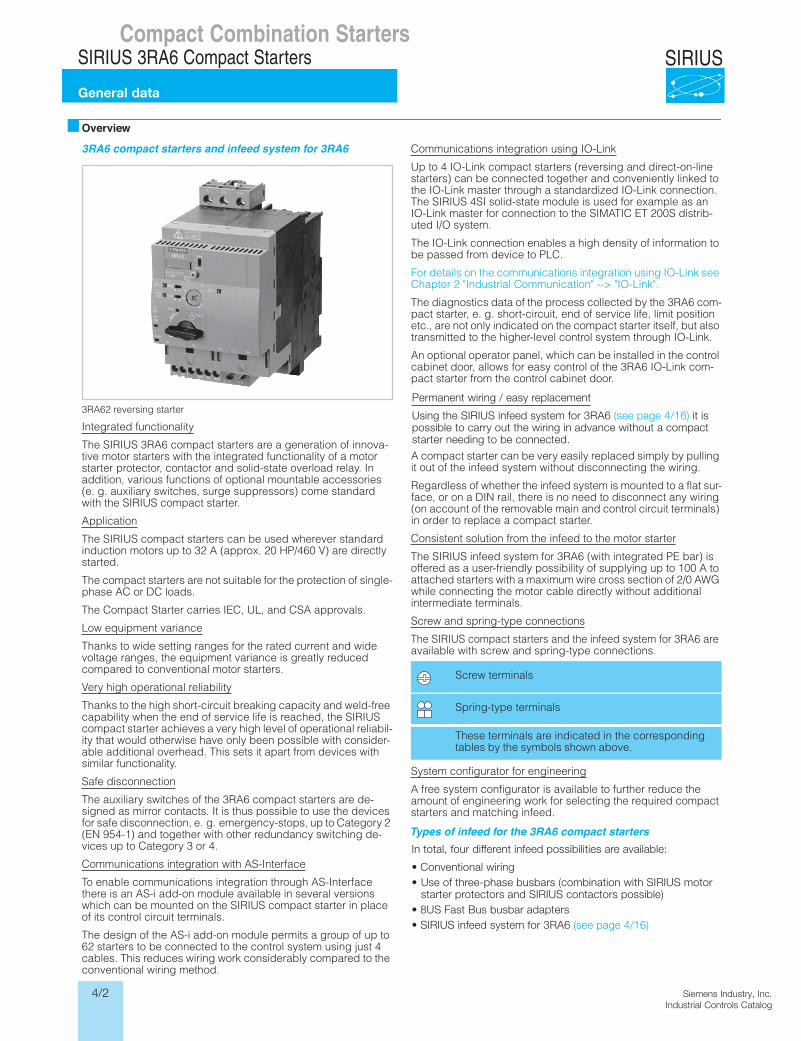
3RA62 reversing starter
Integrated functionality
The SIRIUS 3RA6 compact starters are a generation of innova-tive motor starters with the integrated functionality of a motor starter protector, contactor and solid-state overload relay. In addition, various functions of optional mountable accessories (e. g. auxiliary switches, surge suppressors) come standard with the SIRIUS compact starter.
Application
The SIRIUS compact starters can be used wherever standard induction motors up to 32 A (approx. 20 HP/460 V) are directly started.
The compact starters are not suitable for the protection of single-phase AC or DC loads.
The Compact Starter carries IEC, UL, and CSA approvals.
Low equipment variance
Thanks to wide setting ranges for the rated current and wide voltage ranges, the equipment variance is greatly reduced compared to conventional motor starters.
Very high operational reliability
Thanks to the high short-circuit breaking capacity and weld-free capability when the end of service life is reached, the SIRIUS compact starter achieves a very high level of operational reliabil-ity that would otherwise have only been possible with consider-able additional overhead. This sets it apart from devices with similar functionality.
Safe disconnection
The auxiliary switches of the 3RA6 compact starters are de-signed as mirror contacts. It is thus possible to use the devices for safe disconnection, e. g. emergency-stops, up to Category 2 (EN 954-1) and together with other redundancy switching de-vices up to Category 3 or 4.
Communications integration with AS-Interface
To enable communications integration through AS-Interface there is an AS-i add-on module available in several versions which can be mounted on the SIRIUS compact starter in place of its control circuit terminals.
The design of the AS-i add-on module permits a group of up to 62 starters to be connected to the control system using just 4 cables. This reduces wiring work considerably compared to the conventional wiring method.
Communications integration using IO-Link
Up to 4 IO-Link compact starters (reversing and direct-on-line starters) can be connected together and conveniently linked to the IO-Link master through a standardized IO-Link connection. The SIRIUS 4SI solid-state module is used for example as an IO-Link master for connection to the SIMATIC ET 200S distrib-uted I/O system.
The IO-Link connection enables a high density of information to be passed from device to PLC.
For details on the communications integration using IO-Link see Chapter 2 "Industrial Communication" --> "IO-Link".
The diagnostics data of the process collected by the 3RA6 com-pact starter, e. g. short-circuit, end of service life, limit position etc., are not only indicated on the compact starter itself, but also transmitted to the higher-level control system through IO-Link.
An optional operator panel, which can be installed in the control cabinet door, allows for easy control of the 3RA6 IO-Link com-pact starter from the control cabinet door.
A compact starter can be very easily replaced simply by pulling it out of the infeed system without disconnecting the wiring.
Regardless of whether the infeed system is mounted to a flat sur-face, or on a DIN rail, there is no need to disconnect any wiring (on account of the removable main and control circuit terminals) in order to replace a compact starter.
Consistent solution from the infeed to the motor starter
The SIRIUS infeed system for 3RA6 (with integrated PE bar) is offered as a user-friendly possibility of supplying up to 100 A to attached starters with a maximum wire cross section of 2/0 AWG while connecting the motor cable directly without additional intermediate terminals.
Screw and spring-type connections
The SIRIUS compact starters and the infeed system for 3RA6 are available with screw and spring-type connections.
System configurator for engineering
A free system configurator is available to further reduce the amount of engineering work for selecting the required compact starters and matching infeed.
Types of infeed for the 3RA6 compact starters
Screw terminals
Spring-type terminals
These terminals are indicated in the corresponding tables by the symbols shown above.
LV1N_06_03.fm Page 32 Tuesday, September 24, 2013 11:35 AM
Permanent wiring / easy replacement
Using the SIRIUS infeed system for 3RA6 (see page 4/16) it ispossible to carry out the wiring in advance without a compact starter needing to be connected.
In total, four different infeed possibilities are available:
• Conventional wiring• Use of three-phase busbars (combination with SIRIUS motor
starter protectors and SIRIUS contactors possible)• 8US Fast Bus busbar adapters• SIRIUS infeed system for 3RA6 (see page 4/16)
4/3Siemens Industry, Inc.Industrial Controls Catalog
SIRIUS
Siemens / Industrial Controls Previous folio: LV1 6/58
Compact Combination StartersSIRIUS 3RA6 Compact Starters
General data
For Operation in the Control CabinetSIRIUS 3RA6 Compact Starters
General data
6/33SIRIUS Innovations Supplement 2012
6
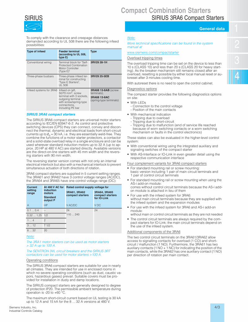
To comply with the clearance and creepage distances demanded according to UL 508 there are the following infeed possibilities:
SIRIUS 3RA6 compact startersThe SIRIUS 3RA6 compact starters are universal motor starters according to IEC/EN 60947-6-2. As control and protective switching devices (CPS) they can connect, convey and discon-nect the thermal, dynamic and electrical loads from short-circuit currents up to �Iq = 30 kA, i.e. they are essentially weld-free. They combine the functions of a motor starter protectors, a contactor and a solid-state overload relay in a single enclosure and can be used wherever standard induction motors up to 32 A (up to ap-prox. 20 HP at 480 V AC) are started directly. Available versions are the direct-on-line starters with 45 mm width and the revers-ing starters with 90 mm width.
The reversing starter version comes with not only an internal electrical interlock but also with a mechanical interlock to prevent simultaneous actuation of both directions of rotation.
3RA6 compact starters are supplied in 5 current setting ranges. The 3RA61 and 3RA62 have 3 control voltage ranges (AC/DC), the 3RA64 and 3RA65 have one control voltage range (DC):
Note:
The 3RA1 motor starters can be used as motor starters > 32 A up to 100 A.
The SENTRON 3VL circuit breakers and the SIRIUS 3RT contactors can be used for motor starters >100 A.
Operating conditions
The SIRIUS 3RA6 compact starters are suitable for use in nearly all climates. They are intended for use in enclosed rooms in which no severe operating conditions (such as dust, caustic va-pors, hazardous gases) prevail. Suitable covers must be pro-vided for installation in dusty and damp locations.
The SIRIUS compact starters are generally designed to degree of protection IP20. The permissible ambient temperature during operation is -20 to +60 °C.
The maximum short-circuit current based on UL testing is 30 kA up to 12 A and 15 kA for the 8 ... 32 A versions at 480 V.
Note:
More technical specifications can be found in the system manual at
www.siemens.com/compactstarter
Overload tripping times
The overload tripping time can be set on the device to less than 10 s (CLASS 10) and less than 20 s (CLASS 20 for heavy start-ing). As the breaker mechanism still remains closed after an overload, resetting is possible by either local manual reset or au-toreset after 3 minutes cooling time.
With autoreset there is no need to open the control cabinet.
Diagnostics options
The compact starter provides the following diagnostics options on site:• With LEDs
- Connection to the control voltage- Position of the main contacts
• With mechanical indication- Tripping due to overload- Tripping due to short-circuit- Tripping due to malfunction (end of service life reached
because of worn switching contacts or a worn switching mechanism or faults in the control electronics)
These states can also be evaluated in the higher-level control system:• With conventional wiring using the integrated auxiliary and
signaling switches of the compact starter• With AS-Interface or IO-Link in even greater detail using the
respective communication interface
Four complement variants for 3RA6 compact starters• For standard mounting rail or screw mounting:
basic version including 1 pair of main circuit terminals and 1 pair of control circuit terminals
• For standard mounting rail or screw mounting when using the AS-i add-on module:comes without control circuit terminals because the AS-i add-on module is attached in lieu of them
• For use with the infeed system for 3RA6:without main circuit terminals because they are supplied with the infeed system and the expansion modules
• For use with the infeed system for 3RA6 and AS-i add-on module:without main or control circuit terminals as they are not needed
• The control circuit terminals are always required by the com-pact starters for IO-Link; the main circuit terminals depend on the use of the infeed system.
Additional components of the 3RA6
The two control circuit terminals on the 3RA61/3RA62 allow access to signalling contacts for overload (1 CO) and short-circuit / malfunction (1 NO). Furthermore, the 3RA61 has two auxiliary contacts (1 NO + 1 NC) for indicating the position of the main contacts, while the 3RA62 has one auxiliary contact (1 NO) per direction of rotation per main contact.
Type of infeed Feeder terminal(according to UL 508,type E)
Type
Conventional wiring Terminal block for "Self-Protected Combination Motor Controller (Type E)"
3RV29 28-1H
Three-phase busbars Three-phase infeed ter-minal for constructing "Type E Starters", UL 508
3RV29 25-5EB
Infeed systems for 3RA6 Infeed on left, 50/70 mm2, screw terminal with 3 sockets, outgoing terminal with screw/spring-type connections, including PE bar
3RA68 13-8AB (screw terminals),
3RA68 13-8AC(spring-type terminals)
Currentsettingrange
At 460 V AC forinductionmotorsStandardoutput P
Rated control supply voltage for
3RA61, 3RA62compact starters
3RA64, 3RA65compact startersfor IO-Link
A HP V AC/DC V DC
0.1 ... 0.4 -- 24
110 ... 240
24
0.32 ... 1.25 1/2
1 ... 4 2
3 ... 12 7 1/2
8 ... 32 20
LV1N_06_03.fm Page 33 Tuesday, September 24, 2013 12:19 PM
4/4 Siemens Industry, Inc.Industrial Controls Catalog
SIRIUS
Overview
Compact Combination Starters3RA6 Compact Starters
Siemens / Industrial Controls Previous folio: LV1T 6/92
Function
Trip units
The SIRIUS 3RA6 compact starters are equipped with the follow-ing trip units:• Inverse-time delayed solid-state overload release• Instantaneous electronic trip unit (electromagnetic short-
circuit release)
The overload releases can be adjusted in accordance with the load current.
The electronic trip units are permanently set to a value 13 times the maximum rated current of the 4 A, 12 A and 32 A starter and thus enable trouble-free starting of motors.
Trip classes
The trip classes of electronically delayed trip units are based on the tripping time (tA) at 7.2 times the set current in the cold state (excerpt from IEC 60947-4):
CLASS 10: 4s < tA < 10 s
CLASS 20: 6s < tA < 20 s (for heavy starting)
The compact starter must trip within this time.
Disconnection due to malfunction
The following malfunctions can be detected:• End of service life
- Worn switching contacts (for electrical endurance see"Technical data")
- Worn switching mechanisms (for mechanical endurance see "Technical data")
• Faults in the control electronics
Short-circuit protection
If a short-circuit occurs, the short-circuit releases of the SIRIUS 3RA6 compact starters isolate the faulty motor starter from the network and thus prevent further damage. The short-circuit releases are factory-set to 14 times the value of the max-imum rated current In of the device.
The SIRIUS compact starters have a short-circuit breaking ca-pacity up to 30 kA at a voltage of 480 V AC.
Overload relay function
In the event of an overload, the compact starter switches off without the breaker mechanism being opened.
The overload trip can be signaled to the higher-level control sys-tem through an integrated signal switch.
The overload signal can be reset automatically or by means of a manual reset.
Control through AS-Interface
For control through AS-Interface, the AS-i add-on module is mounted instead of the two control circuit terminals on the SIRIUS 3RA6 compact starters (direct-on-line starters and re-versing starters).
The AS-i auxiliary voltage and the AS-i data line are installed on the AS-i add-on module easily and quickly without tools by means of two plug-in connector blocks with insulation displace-ment connection.
The AS-i add-on module is equipped with the latest A/B technol-ogy and has an addressing socket onboard.
An addressing unit is required and can be ordered for address-ing the AS-i add-on module.
Bit assignment (see below) is similar to that for the SIRIUS motor starters, which means that the same programming can be used here.
A 24 V DC PELV power supply unit according to EN 61140 safety class III is required for the auxiliary voltage.
The AS-i data line is supplied with voltage by means of a 30 V DC AS-i power supply unit and is controlled by means of the AS-i master.
The AS-i add-on modules are available in the following five versions:• AS-i add-on module for compact starters• AS-i add-on module for compact starters with two local inputs
for safe disconnection of the "clockwise rotation" or "counter-clockwise rotation" outputs
• AS-i add-on module with two free external inputs• AS-i add-on module with two free external outputs• AS-i add-on module with one free external input and output
The AS-i add-on module can only be used with compact starters with a control voltage of 24 V AC/DC.
Integrated auxiliary switches
The control circuit terminals of the SIRIUS 3RA6 compact start-ers have the following connections:• A1/A2 for the control voltage for 3RA61,
A1/A2 and B1/B2 for the control voltage for 3RA62• "Overload" signal switch• "Fault" signal switch, e. g. "short-circuit"• Internal auxiliary switch for position of the main contacts (in
case of direct-on-line starters: 1 NO + 1 NC with mirror contact to the main contact; in case of reversing starters: 2 NO)
DI 0.0 ready
DI 0.1 motor on
DI 0.2 group fault
DI 0.3 group warning
DO 0.0 motor on or motor clockwise
DO 0.1 motor counterclockwise
4/5Siemens Industry, Inc.Industrial Controls Catalog
SIRIUS
Overview
Compact Combination Starters3RA6 Compact Starters
Siemens / Industrial Controls Previous folio: LV1T 6/90
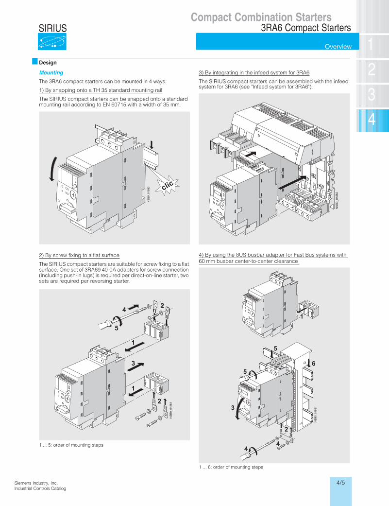
Design
MountingThe 3RA6 compact starters can be mounted in 4 ways:
1) By snapping onto a TH 35 standard mounting rail
The SIRIUS compact starters can be snapped onto a standard mounting rail according to EN 60715 with a width of 35 mm.
2) By screw fixing to a flat surface
The SIRIUS compact starters are suitable for screw fixing to a flat surface. One set of 3RA69 40-0A adapters for screw connection (including push-in lugs) is required per direct-on-line starter, two sets are required per reversing starter.
1 ... 5: order of mounting steps
3) By integrating in the infeed system for 3RA6
The SIRIUS compact starters can be assembled with the infeed system for 3RA6 (see "Infeed system for 3RA6").
4) By using the 8US busbar adapter for Fast Bus systems with 60 mm busbar center-to-center clearance
1 ... 6: order of mounting steps
NS
B0_
0188
0 clic
NSB
0_01
881
1
1
2
2
3
4
5N
SB
0_01
882
NS
B0_
0192
1
4
3
2
5
5
6
4
1
4/6 Siemens Industry, Inc.Industrial Controls Catalog
SIRIUS
Overview
Compact Combination Starters3RA6 Compact Starters
Siemens / Industrial Controls Previous folio: LV1T 6/91
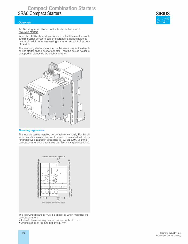
4a) By using an additional device holder in the case of reversing starters
When the 8US busbar adapter is used on Fast Bus systems with 60 mm busbar center-to-center clearance, a device holder is needed in addition for a reversing starter on account of its dou-ble width.
The reversing starter is mounted in the same way as the direct-on-line starter on the busbar adapter. Then the device holder is snapped on alongside the busbar adapter.
Mounting regulations
The module can be installed horizontally or vertically. For the dif-ferent installations attention must be paid however to limit values for protective separation according to IEC/EN 60947-2 of the compact starters (for details see the "Technical specifications").
The following distances must be observed when mounting the compact starters:• Lateral clearance to grounded components: 10 mm• Arcing space at top and bottom: 30 mm
NS
B0_
0192
2
NS
B0_
0188
3
> 10
> 3
0> 10
> 3
0
4/7Siemens Industry, Inc.Industrial Controls Catalog
SIRIUS
Product Category: IEC
Siemens / Industrial Controls Previous folio: LV1 6/59
Compact Combination StartersSIRIUS 3RA6 Compact Starters
3RA61, 3RA62 compact starters3RA61 direct-on-line starters
For Operation in the Control CabinetSIRIUS 3RA6 Compact Starters3RA61, 3RA62 compact starters3RA61 direct-on-line starters
6/40 SIRIUS Innovations Supplement 2012 Illustrations are approximate
6
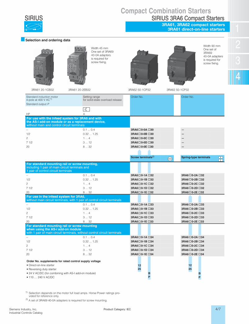
Selection and ordering data
1) Selection depends on the motor full load amps. Horse Power ratings pro-vided for reference only.
Standard induction motor 4-pole at 400 V AC1)
Standard output P
Setting rangefor solid-state overload release
Order No. Order No.
APH
For use with the infeed system for 3RA6 and withthe AS-i add-on module or as a replacement device,without main and control circuit terminals
4.0 ... 1.0-- 3RA6 0-0A @30 —52.1 ... 23.02/1 3RA6 0-0B @30 —
4 ... 12 3RA6 0-0C @30 —21 ... 32/1 7 3RA6 0-0D @30 —23 ... 802 3RA6 0-0E @
@@@@@ 30 —
Screw terminals Spring-type terminals
For standard mounting rail or screw mounting,including 1 pair of main circuit terminals and1 pair of control circuit terminals
4.0 ... 1.0-- 3RA6 0-1A @32 3RA6 0-2A @3252.1 ... 23.02/1 3RA6 0-1B @32 3RA6 0-2B @32
4 ... 12 3RA6 0-1C @32 3RA6 0-2C @3221 ... 32/1 7 3RA6 0-1D @32 3RA6 0-2D @3223 ... 802 3RA6 0-1E @32 3RA6 0-2E @32
For use in the infeed system for 3RA6,without main circuit terminals, with 1 pair of control circuit terminals
4.0 ... 1.0-- 3RA6 0-1A @33 3RA6 0-2A @3352.1 ... 23.02/1 3RA6 0-1B @33 3RA6 0-2B @33
4 ... 12 3RA6 0-1C @33 3RA6 0-2C @3321 ... 32/1 7 3RA6 0-1D @33 3RA6 0-2D @3323 ... 802 3RA6 0-1E @33 3RA6 0-2E @33
For standard mounting rail or screw mountingwhen using the AS-i add-on modulewith 1 pair of main circuit terminals, without control circuit terminals
4.0 ... 1.0-- 3RA6 0-1A @34 3RA6 0-2A @3452.1 ... 23.02/1 3RA6 0-1B @34 3RA6 0-2B @34
4 ... 12 3RA6 0-1C @34 3RA6 0-2C @3421 ... 32/1 7 3RA6 0-1D @34 3RA6 0-2D @3423 ... 802 3RA6 0-1E @34 3RA6 0-2E @34
LV1N_06_03.fm Page 40 Tuesday, September 24, 2013 11:35 AM
Order No. supplements for rated control supply voltage • Direct-on-line starter • Reversing duty starter • 24 V AC/DC (for combining with AS-I add-on module) • 110 … 240 V AC/DC
1225
BP
1225
BP
A set of 3RA69 40-0A adapters is required for screw mounting. 2)
@@@@@
@@@@@
@@@@@
@@@@@
@@@@@
@@@@@
2)
3RA61 20-1CB32 3RA62 50-1CP323RA61 20-2EB32
Width 45 mmOne set of 3RA69 40-0A adapters is required for screw fixing.
Width 90 mmOne set of 3RA6940-0A adapters is required for screw fixing.
3RA62 50-1CP32
4/8 Siemens Industry, Inc.Industrial Controls Catalog
SIRIUS
Siemens / Industrial Controls Previous folio: LV1 6/61
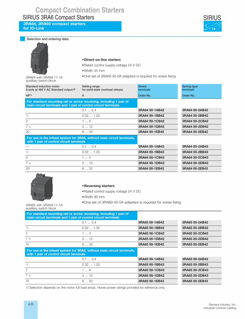
Selection and ordering data
• Direct-on-line starters
• Rated control supply voltage 24 V DC
• Width 45 mm
• One set of 3RA69 40-0A adapters is required for screw fixing3RA64 with 3RA69 11-1Aauxilliary switch block
Standard induction motor 3-pole at 460 V AC Standard output P
Setting rangefor solid-state overload release
Screw terminals
Spring-type terminals
HP1) A Order No. Order No.
For standard mounting rail or screw moutning, including 1 pair of main circuit terminals and 1 pair of control circuit terminals
-- 0.1 … 0.4 3RA64 00-1AB42 3RA64 00-2AB421⁄2 0.32 … 1.25 3RA64 00-1BB42 3RA64 00-2BB42
2 1 … 4 3RA64 00-1CB42 3RA64 00-2CB42
7 1⁄2 3 … 12 3RA64 00-1DB42 3RA64 00-2DB42
20 8 … 32 3RA64 00-1EB42 3RA64 00-2EB42
For use in the infeed system for 3RA6, without main circuit terminals, with 1 pair of control circuit terminals
— 0.1 … 0.4 3RA64 00-1AB43 3RA64 00-2AB431⁄2 0.32 … 1.25 3RA64 00-1BB43 3RA64 00-2BB43
2 1 … 4 3RA64 00-1CB43 3RA64 00-2CB43
7 1⁄2 3 … 12 3RA64 00-1DB43 3RA64 00-2DB43
20 8 … 32 3RA64 00-1EB43 3RA64 00-2EB43
• Reversing starters
• Rated control supply voltage 24 V DC
• Width 90 mm
• One set of 3RA69 40-0A adapters is required for screw fixing3RA65 with 3RA69 11-1Aauxilliary switch block
For standard mounting rail or screw moutning, including 1 pair of main circuit terminals and 1 pair of control circuit terminals
-- 0.1 … 0.4 3RA65 00-1AB42 3RA65 00-2AB421⁄2 0.32 … 1.25 3RA65 00-1BB42 3RA65 00-2BB42
2 1 … 4 3RA65 00-1CB42 3RA65 00-2CB42
7 1⁄2 3 … 12 3RA65 00-1DB42 3RA65 00-2DB42
20 8 … 32 3RA65 00-1EB42 3RA65 00-2EB42
For use in the infeed system for 3RA6, without main circuit terminals, with 1 pair of control circuit terminals
-- 0.1 … 0.4 3RA65 00-1AB43 3RA65 00-2AB431⁄2 0.32 … 1.25 3RA65 00-1BB43 3RA65 00-2BB43
2 1 … 4 3RA65 00-1CB43 3RA65 00-2CB43
7 1⁄2 3 … 12 3RA65 00-1DB43 3RA65 00-2DB43
20 8 … 32 3RA65 00-1EB43 3RA65 00-2EB43
1) Selection depends on the motor full load amps. Horse power ratings provided for reference only.
Compact Combination StartersSIRIUS 3RA6 Compact Starters3RA64, 3RA65 compact starters for IO-Link
4/9Siemens Industry, Inc.Industrial Controls Catalog
SIRIUSFor Operation in the Control Cabinet
SIRIUS 3RA6 Compact Starters
Accessories
6/44 SIRIUS Innovations Supplement 2012
6
Overview
Accessories for SIRIUS 3RA6 compact startersThe following accessories are available for the 3RA6 compact starters:
• External auxiliary switch blocks: Snap-on auxiliary switch as versions 2 NO, 2 NC and 1 NO +1 NC with screw or spring-type connections; the contacts of the auxiliary switch block open and close jointly with the main contacts of the compact starter. The NC contacts are designed as mirror contacts.
• Control kit: aid for manually closing the main contacts in order to evaluate the wiring and motor direction under conditions of short-circuit protection
• Adapter for screw mounting the compact starter, including push-in lugs
• Main circuit terminals: Available in screw and spring-type ter-minals
• Main circuit terminals for mixed connection method:With the main circuit terminal for the mixed connection method it is also possible in the main circuit to change over from the screw connection method on the incoming side to the spring-type connection method on the outgoing side.This enables for example the side-by-side mounting of several compact starters and their cost-effective connection using the three-phase busbars on the infeed side. The motors are then directly connected by the quick and reliably contacting spring-type connection method.
Accessories for UL applicationsThe terminal block for "Self-Protected Combination Motor Controller", type E is available for complying with the clearance and creepage distances according to UL 508.
Accessories for infeed using three-phase busbar systemsThe three-phase busbars can be used as an easy, time-saving and clearly arranged means of feeding SIRIUS 3RA6 compact starters with screw connection. Motor starter protectors size S00 and S0 can also be integrated.
The busbars are suitable for between 2 and 5 devices. However, any kind of extension up to a maximum summation current of 63 A is possible by clamping the terminals of an additional bus-bar (rotated by 180°) underneath the terminals of the respective last motor circuit protector.
A connecting piece is required for the combination with motor starter protector size S00. S00 and S0 motor starter protectors of the 3RV2 series do not require the additional connecting piece. The motor starter protectors are supplied by appropriate feeder terminals. Special feeder terminals are required for constructing "Type E Starters" according to UL/CSA.
The three-phase busbar systems are finger-safe but empty connection terminals must be fitted with covers. They are de-signed for any short-circuit stress which can occur at the output side of connected SIRIUS 3RA6 compact starters or motor starter protectors.
8US Fast Bus busbar adapters for 60 mm systemsThe compact starters are mounted directly with the aid of busbar adapters on the Fast Bus busbar systems with 60 mm center-to-center clearance in order to save space and to reduce infeed times and costs. These starters are suitable for copper busbars with a width from 12 to 30 mm. The busbars can be 5 mm or 10 mm thick.
The 8US Fast Bus busbar system can be loaded with a maxi-mum summation current of 1400A.
The "reversing starter" version requires a device holder along side the busbar adapter for lateral mounting.
The compact starters are snapped onto the adapter and con-nected on the line side. This prepared unit is then plugged di-rectly onto the busbar system, and is thus connected both me-chanically and electrically at the same time.
Accessories for operation with closed control cabinet doorsDoor-coupling rotary operating mechanisms for standard and emergency-stop applications are available for operating the compact starter with closed control cabinet doors.
Accessories for SIRIUS 3RA6 compact starters in IO-LinkversionThe following accessories are available specifically for the 3RA64, 3RA65 compact starters:• The 4SI SIRIUS solid-state module as IO-Link master allows
for the simple and economical connection of SIRIUS controls with IO-Link (e.g up to four groups of 4 compact starters) to the multifunctional SIMATIC ET 200S distributed I/O system.
• Additional connection cables for side-by-side mounting of up to 4 compact starters
• Operator panel for local control and diagnostics of up to 4 compact starters coupled to each other
LV1N_06_03.fm Page 44 Tuesday, September 24, 2013 11:35 AM
• AS-i add-on module: see AS-Interface Add-On Modules for3RA6, page 4/14
For more accessories such as incoming and outgoing terminals, flat copper profiles etc., see Section 5 “Fastbus Busbar Systems”.
Compact Combination StartersSIRIUS 3RA6 Compact Starters
Accessories
4/10 Siemens Industry, Inc.Industrial Controls Catalog
SIRIUSCompact Combination Starters
SIRIUS 3RA6 Compact Starters
Accessories
For Operation in the Control CabinetSIRIUS 3RA6 Compact Starters
Accessories
6/45SIRIUS Innovations Supplement 2012Illustrations are approximate
6
Selection and ordering data Version Order No. Std.
packqty.
Weightapprox.
kg
Accessories for 3RA6 compact starters
3RA69 50-0A
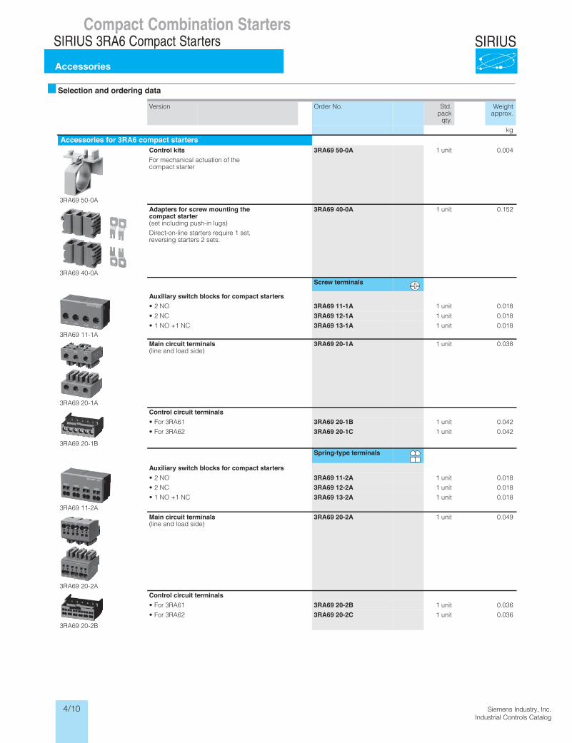
Control kitsFor mechanical actuation of the compact starter
3RA69 50-0A 1 unit 0.004
3RA69 40-0A
Adapters for screw mounting thecompact starter(set including push-in lugs)
Direct-on-line starters require 1 set, reversing starters 2 sets.
3RA69 40-0A 1 unit 0.152
Screw terminals
3RA69 11-1A
Auxiliary switch blocks for compact starters• 2 NO 3RA69 11-1A 1 unit 0.018
• 2 NC 3RA69 12-1A 1 unit 0.018
• 1 NO +1 NC 3RA69 13-1A 1 unit 0.018
3RA69 20-1A
Main circuit terminals(line and load side)
3RA69 20-1A 1 unit 0.038
3RA69 20-1B
Control circuit terminals• For 3RA61 3RA69 20-1B 1 unit 0.042
• For 3RA62 3RA69 20-1C 1 unit 0.042
Spring-type terminals
3RA69 11-2A
Auxiliary switch blocks for compact starters• 2 NO 3RA69 11-2A 1 unit 0.018
• 2 NC 3RA69 12-2A 1 unit 0.018
• 1 NO +1 NC 3RA69 13-2A 1 unit 0.018
3RA69 20-2A
Main circuit terminals(line and load side)
3RA69 20-2A 1 unit 0.049
3RA69 20-2B
Control circuit terminals• For 3RA61 3RA69 20-2B 1 unit 0.036
• For 3RA62 3RA69 20-2C 1 unit 0.036
* You can order this quantity or a multiple thereof.
LV1N_06_03.fm Page 45 Friday, October 11, 2013 3:23 PM
4/11Siemens Industry, Inc.Industrial Controls Catalog
SIRIUSCompact Combination Starters
SIRIUS 3RA6 Compact Starters
Accessories
For Operation in the Control CabinetSIRIUS 3RA6 Compact Starters
Accessories
6/46 SIRIUS Innovations Supplement 2012 Illustrations are approximate
6
1) 10-pole connection cables are required for EMERGENCY-STOP group concepts.
2) Is included in the scope of supply of the SIRIUS 3RA6 compact starter in IO-Link version.
Version Order No. Std.pack
qty.
Weightapprox.
kg
Accessories for 3RA6 compact starters (continued)
3RA69 20-3A
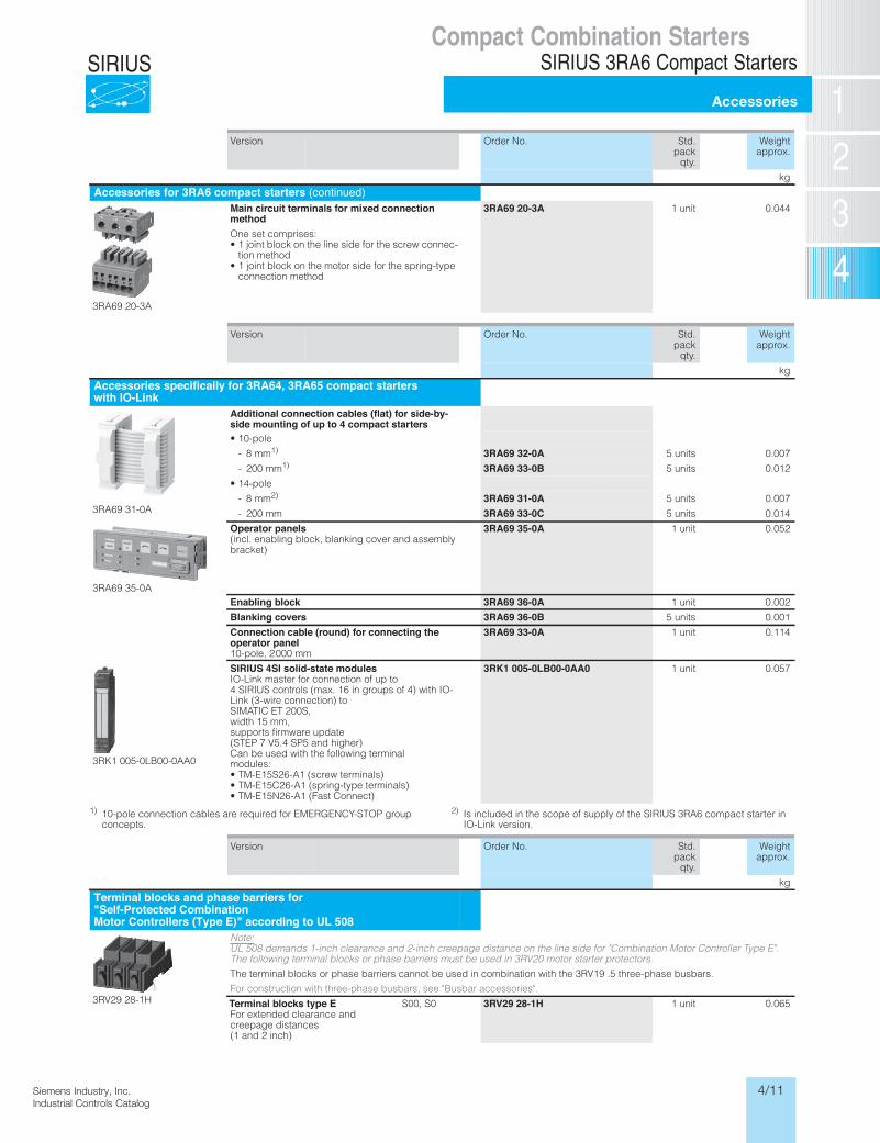
Main circuit terminals for mixed connectionmethodOne set comprises:• 1 joint block on the line side for the screw connec-
tion method • 1 joint block on the motor side for the spring-type
connection method
3RA69 20-3A 1 unit 0.044
Version Order No. Std.pack
qty.
Weightapprox.
kg
Accessories specifically for 3RA64, 3RA65 compact starterswith IO-Link
3RA69 31-0A
Additional connection cables (flat) for side-by-side mounting of up to 4 compact starters• 10-pole
- 8 mm1) 3RA69 32-0A 5 units 0.007
- 200 mm1) 3RA69 33-0B 5 units 0.012
• 14-pole
- 8 mm2) 3RA69 31-0A 5 units 0.007
- 200 mm 3RA69 33-0C 5 units 0.014
3RA69 35-0A
Operator panels(incl. enabling block, blanking cover and assembly bracket)
3RA69 35-0A 1 unit 0.052
Enabling block 3RA69 36-0A 1 unit 0.002
Blanking covers 3RA69 36-0B 5 units 0.001
Connection cable (round) for connecting theoperator panel10-pole, 2 000 mm
3RA69 33-0A 1 unit 0.114
3RK1 005-0LB00-0AA0
SIRIUS 4SI solid-state modulesIO-Link master for connection of up to 4 SIRIUS controls (max. 16 in groups of 4) with IO-Link (3-wire connection) to SIMATIC ET 200S, width 15 mm, supports firmware update (STEP 7 V5.4 SP5 and higher) Can be used with the following terminal modules:• TM-E15S26-A1 (screw terminals)• TM-E15C26-A1 (spring-type terminals)• TM-E15N26-A1 (Fast Connect)
3RK1 005-0LB00-0AA0 1 unit 0.057
Version Order No. Std.pack
qty.
Weightapprox.
kg
Terminal blocks and phase barriers for"Self-Protected CombinationMotor Controllers (Type E)" according to UL 508
3RV29 28-1H
Note: UL 508 demands 1-inch clearance and 2-inch creepage distance on the line side for "Combination Motor Controller Type E". The following terminal blocks or phase barriers must be used in 3RV20 motor starter protectors.
The terminal blocks or phase barriers cannot be used in combination with the 3RV19 .5 three-phase busbars.
For construction with three-phase busbars, see "Busbar accessories".
Terminal blocks type EFor extended clearance and creepage distances (1 and 2 inch)
S00, S0 3RV29 28-1H 1 unit 0.065
* You can order this quantity or a multiple thereof.
LV1N_06_03.fm Page 46 Friday, October 11, 2013 3:23 PM
4/12 Siemens Industry, Inc.Industrial Controls Catalog
SIRIUSCompact Combination Starters
SIRIUS 3RA6 Compact Starters
Accessories
For Operation in the Control CabinetSIRIUS 3RA6 Compact Starters
Accessories
6/47SIRIUS Innovations Supplement 2012Illustrations are approximate
6
1) Not suitable for 3RV11/3RV21 motor starter protectors for motor protection with overload relay function and for 3RV17/3RV27 and 3RV18/3RV28 motor starter protectors according to UL 489 / CSA C22.2 No.5-02.The joint clamping of motor starter protectors size S00 and size S0 is not possible due to the different modular spacings and the different height of the terminals. The 3RV19 15-5DB connecting piece is available for con-necting the compact starters to motor starter protectors size S00.
1) This terminal is connected in place of a switch, please take the space requirement into account.
Number of compact starters and motor starter protectors that can be connected
Modu-lar spacing
Rated current In at 690 V
For motor starter protector
Order No. Std.pack
qty.
Weightapprox.
without lateral acces-sories
mm ASize
kg
Three-phase busbars for infeed with 3RA6
3RV19 15-1AB
3RV19 15-1BB
3RV19 15-1CB
3RV19 15-1DB
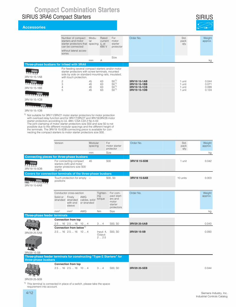
For feeding several compact starters and/or motor starter protectors with screw terminals, mounted side by side on standard mounting rails, insulated, with touch protection.
2 45 63 S01) 3RV19 15-1AB 1 unit 0.0443 45 63 S01) 3RV19 15-1BB 1 unit 0.0714 45 63 S01) 3RV19 15-1CB 1 unit 0.0995 45 63 S01) 3RV19 15-1DB 1 unit 0.124
Version Modular spacing
For motor starter protector
Order No. Std.pack
qty.
Weightapprox.
mm Size kg
Connecting pieces for three-phase busbars
3RV19 15-5DB
For connecting compact starters (left) and motor starter protectors size S00 (right)
45 S00 3RV19 15-5DB 1 unit 0.042
Covers for connection terminals of the three-phase busbars
3RV19 15-6AB
Touch protection for empty positions
-- S00, S0 3RV19 15-6AB 10 units 0.003
Conductor cross-section Tighten-ing torque
For com-pact start-ers and motor starter protectors
Order No. Weightapprox.Solid or
strandedFinely stranded with end sleeve
AWG cables, solid or stranded
mm² mm² AWG Nm Size kg
Three-phase feeder terminals
3RV29 25-5AB
3RV29 15-5B
Connection from top2.5 ... 16 2.5 ... 16 10 ... 4 3 ... 4 S00, S0 3RV29 25-5AB 0.043
Connection from below1)
2.5 ... 16 2.5 ... 16 10 ... 4 Input: 4, Output: 2 ... 2.5
S00, S0 3RV29 15-5B 0.093
Three-phase feeder terminals for constructing "Type E Starters" forthree-phase busbars
3RV29 25-5EB
Connection from top2.5 ... 16 2.5 ... 16 10 ... 4 3 ... 4 S00, S0 3RV29 25-5EB 0.044
* You can order this quantity or a multiple thereof.
LV1N_06_03.fm Page 47 Friday, October 11, 2013 3:23 PM
4/13Siemens Industry, Inc.Industrial Controls Catalog
SIRIUSCompact Combination Starters
SIRIUS 3RA6 Compact Starters
Accessories
For Operation in the Control CabinetSIRIUS 3RA6 Compact Starters
Accessories
6/49SIRIUS Innovations Supplement 2012Illustrations are approximate
6
1) PC labeling system for individual inscription of unit labeling plates available from: Murrplastik Systems, Inc. www.murrplastik.com .
Version Order No. Std.pack
qty.
Weightapprox.
kg
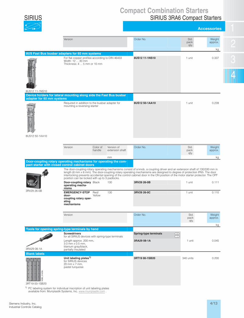
Tools for opening spring-type terminals by hand
3RA29 08-1A
Screwdriversfor all SIRIUS devices with spring-type terminals
Spring-type terminals
Length approx. 200 mm, 3.0 mm x 0.5 mm, titanium gray/black, partially insulated
3RA29 08-1A 1 unit 0.045
Blank labels
3RT19 00-1SB20
Unit labeling plates1)for SIRIUS devices 20 mm x 7 mm, pastel turquoise
3RT19 00-1SB20 340 units 0.200
NSB
0_01429b
* You can order this quantity or a multiple thereof.
LV1N_06_03.fm Page 49 Friday, October 11, 2013 3:23 PM
Version Order No. Std.pack
qty.
Weightapprox.
kg
8US Fast Bus busbar adapters for 60 mm systems
8US12 11-1NS10
For flat copper profiles according to DIN 46433 Width: 12 ... 30 mm Thickness: 4 ... 5 mm or 10 mm
8US12 11-1NS10 1 unit 0.337
Device holders for lateral mounting along side the Fast Bus busbaradapter for 60 mm systems
8US12 50-1AA10
Required in addition to the busbar adapter for mounting a reversing starter
8US12 50-1AA10 1 unit 0.239
Version Color of handle
Version of extension shaft
Order No. Std.pack
qty.
Weightapprox.
mm kg
Door-coupling rotary operating mechanisms for operating the com-pact starter with closed control cabinet doors
3RV29 26-0B
The door-coupling rotary operating mechanisms consist of a knob, a coupling driver and an extension shaft of 130/330 mm in length (6 mm x 6 mm). The door-coupling rotary operating mechanisms are designed to degree of protection IP65. The door interlocking prevents accidental opening of the control cabinet door in the ON position of the motor starter protector. The OFF position can be locked with up to 3 padlocks.
Door-coupling rotaryoperating mecha-nisms
Black 130 3RV29 26-0B 1 unit 0.111
EMERGENCY-STOPdoor-coupling rotary oper-atingmechanisms
Red/Yellow
130 3RV29 26-0C 1 unit 0.110
4/14 Siemens Industry, Inc.Industrial Controls Catalog
SIRIUSCompact Combination Starters
SIRIUS 3RA6 Compact Starters
Add-on modules for AS-Interface
For Operation in the Control CabinetSIRIUS 3RA6 Compact Starters
Add-on modules for AS-Interface
6/50 SIRIUS Innovations Supplement 2012
6
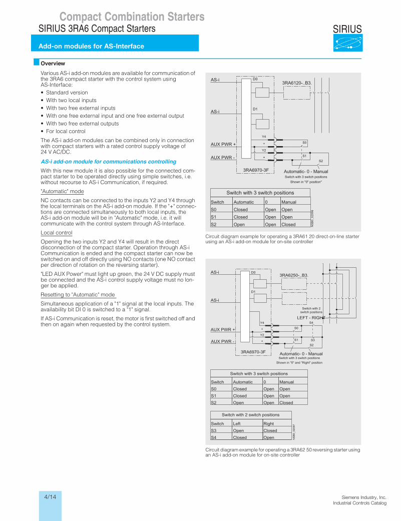
OverviewVarious AS-i add-on modules are available for communication of the 3RA6 compact starter with the control system using AS-Interface:• Standard version• With two local inputs• With two free external inputs• With one free external input and one free external output• With two free external outputs• For local control
The AS-i add-on modules can be combined only in connection with compact starters with a rated control supply voltage of 24 V AC/DC.
AS-i add-on module for communications controllingWith this new module it is also possible for the connected com-pact starter to be operated directly using simple switches, i.e. without recourse to AS-i Communication, if required.
"Automatic" mode
NC contacts can be connected to the inputs Y2 and Y4 through the local terminals on the AS-i add-on module. If the "+" connec-tions are connected simultaneously to both local inputs, the AS-i add-on module will be in "Automatic" mode, i.e. it will communicate with the control system through AS-Interface.
Local control
Opening the two inputs Y2 and Y4 will result in the direct disconnection of the compact starter. Operation through AS-i Communication is ended and the compact starter can now be switched on and off directly using NO contacts (one NO contact per direction of rotation on the reversing starter).
"LED AUX Power" must light up green, the 24 V DC supply must be connected and the AS-i control supply voltage must no lon-ger be applied.
Resetting to "Automatic" mode
Simultaneous application of a "1" signal at the local inputs. The availability bit DI 0 is switched to a "1" signal.
If AS-i Communication is reset, the motor is first switched off and then on again when requested by the control system.
Circuit diagram example for operating a 3RA61 20 direct-on-line starter using an AS-i add-on module for on-site controller
Circuit diagram example for operating a 3RA62 50 reversing starter using an AS-i add-on module for on-site controller
LV1N_06_03.fm Page 50 Tuesday, September 24, 2013 11:35 AM
4/15Siemens Industry, Inc.Industrial Controls Catalog
SIRIUS SIRIUS 3RA6 Compact Starters
Add-on modules for AS-Interface
Compact Combination StartersFor Operation in the Control CabinetSIRIUS 3RA6 Compact Starters
Add-on modules for AS-Interface
6/51SIRIUS Innovations Supplement 2012Illustrations are approximate
6
Selection and ordering data Version Order No. Std.
packqty.
Weightapprox.
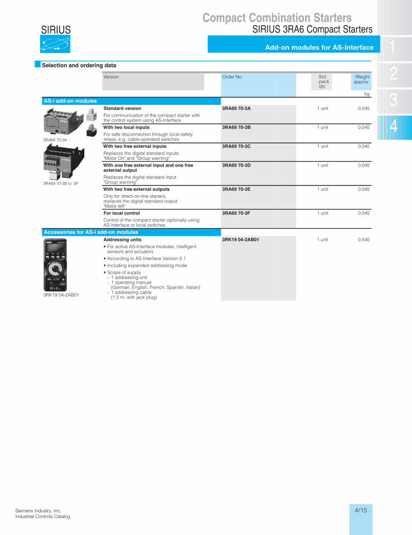
kgAS-i add-on modules
3RA69 70-3A
3RA69 70-3B to -3F
Standard versionFor communication of the compact starter with the control system using AS-Interface
3RA69 70-3A 1 unit 0.045
With two local inputsFor safe disconnection through local safety relays, e.g. cable-operated switches
3RA69 70-3B 1 unit 0.045
With two free external inputsReplaces the digital standard inputs "Motor On" and "Group warning"
3RA69 70-3C 1 unit 0.045
With one free external input and one freeexternal outputReplaces the digital standard input "Group warning"
3RA69 70-3D 1 unit 0.045
With two free external outputsOnly for direct-on-line starters, replaces the digital standard output "Motor left"
3RA69 70-3E 1 unit 0.045
For local controlControl of the compact starter optionally using AS-Interface or local switches
3RA69 70-3F 1 unit 0.045
Accessories for AS-i add-on modules
3RK19 04-2AB01
Addressing units• For active AS-Interface modules, intelligent
sensors and actuators• According to AS-Interface Version 2.1• Including expanded addressing mode• Scope of supply
- 1 addressing unit- 1 operating manual
(German, English, French, Spanish, Italian)- 1 addressing cable
(1.5 m, with jack plug)
3RK19 04-2AB01 1 unit 0.540
* You can order this quantity or a multiple thereof.
LV1N_06_03.fm Page 51 Tuesday, September 24, 2013 11:35 AM
/Users/sspencer/Desktop/Siemens Ind Controls Catalog 2014/Art_Images/04/LV1N_06_03 3RA6 6-51_in grey.pdf
4/16 Siemens Industry, Inc.Industrial Controls Catalog
SIRIUSCompact Combination Starters
3RA6 Compact StartersInfeed systems for 3RA6 up to 100 A
For Operation in the Control CabinetSIRIUS 3RA6 Compact Starters
Infeed systems for 3RA6
6/52 SIRIUS Innovations Supplement 2012
6
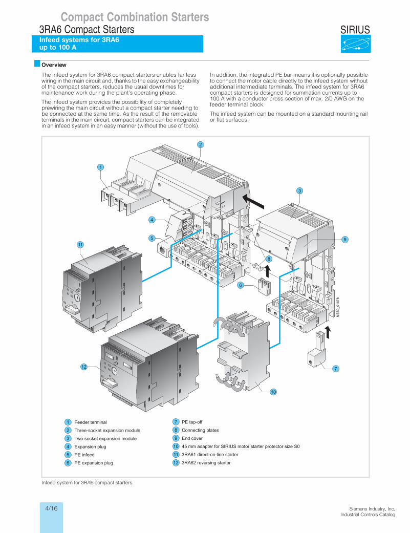
OverviewThe infeed system for 3RA6 compact starters enables far less wiring in the main circuit and, thanks to the easy exchangeability of the compact starters, reduces the usual downtimes for maintenance work during the plant's operating phase.
The infeed system provides the possibility of completely prewiring the main circuit without a compact starter needing to be connected at the same time. As the result of the removable terminals in the main circuit, compact starters can be integrated in an infeed system in an easy manner (without the use of tools).
In addition, the integrated PE bar means it is optionally possible to connect the motor cable directly to the infeed system without additional intermediate terminals. The infeed system for 3RA6 compact starters is designed for summation currents up to 100 A with a conductor cross-section of max. 2/0 AWG on the feeder terminal block.
The infeed system can be mounted on a standard mounting rail or flat surfaces.
Infeed system for 3RA6 compact starters
NS
B0_
0187
8
1
4
5
6
2
3
12
11
7
9
8
10
Feeder terminal
Three-socket expansion module
Two-socket expansion module
Expansion plug
PE infeed
PE expansion plug
1
2
3
6
4
5
PE tap-off
Connecting plates
End cover
45 mm adapter for SIRIUS motor starter protector size S0
3RA61 direct-on-line starter
3RA62 reversing starter
7
8
9
12
10
11
LV1N_06_04.fm Page 52 Tuesday, September 24, 2013 11:55 AM
4/17Siemens Industry, Inc.Industrial Controls Catalog
SIRIUSFor Operation in the Control Cabinet
SIRIUS 3RA6 Compact Starters
Infeed systems for 3RA6
6/53SIRIUS Innovations Supplement 2012
6
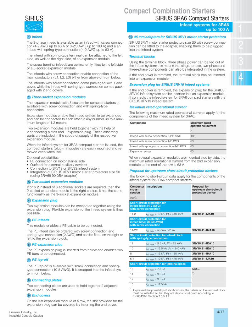
InfeedThe 3-phase infeed is available as an infeed with screw connec-tion (4-2 AWG up to 63 A or 0-2/0 AWG up to 100 A) and a an infeed with spring-type connection (4-2 AWG up to 63 A).
The infeed with spring-type terminal can be attached to the left side, as well as the right side, of an expansion module.
The screw terminal infeeds are permanently fitted to the left side of a 3-socket expansion module.
The infeeds with screw connection enable connection of the main conductors (L1, L2, L3) either from above or from below.
The infeeds with screw connection come packaged with 1 end cover, while the infeed with spring-type connection comes pack-aged with 2 end covers.
Three-socket expansion modulesThe expansion module with 3 sockets for compact starters is available with screw connection and with spring-type connection.
Expansion modules enable the infeed system to be expanded and can be connected to each other in any number up to a max-imum length of 1.2 meters.
Two expansion modules are held together with the help of 2 connecting plates and 1 expansion plug. These assembly parts are included in the scope of supply of the respective expansion module.
When the infeed system for 3RA6 compact starters is used, the compact starters (plug-in modules) are easily mounted and re-moved even when live.
Optional possibilities:• PE connection on motor starter side• Outfeed for external auxiliary devices• Connection to 3RV19 or 3RV29 infeed system• Integration of SIRIUS 3RV1 motor starter protectors size S0
(using 3RA68 90-0BA adapter)
Two-socket expansion modulesIf only 2 instead of 3 additional sockets are required, then the 2-socket expansion module is the right choice. It has the same functionality as the 3-socket expansion module.
Expansion plugTwo expansion modules can be connected together using the expansion plug. Flexible expansion of the infeed system is thus possible.
PE infeedsThis module enables a PE cable to be connected.
The PE infeed can be ordered with screw connection and spring-type connection (2 AWG) and can be fitted on the right or left to the expansion block.
PE expansion plugThe PE expansion plug is inserted from below and enables two PE bars to be connected.
PE tap-off
The PE tap-off is available with screw connection and spring-type connection (10-8 AWG). It is snapped into the infeed sys-tem from below.
Connecting platesTwo connecting plates are used to hold together 2 adjacent expansion modules.
End coversOn the last expansion module of a row, the slot provided for the expansion plug can be covered by inserting the end cover.
45 mm adapters for SIRIUS 3RV1 motor starter protectorsSIRIUS 3RV1 motor starter protectors size S0 with screw connec-tion can be fitted to the adapter, enabling them to be plugged into the infeed system.
Terminal blocksUsing the terminal block, three phase power can be fed out of the infeed system; this means that single-phase, two-phase and three-phase components can also be integrated in the system.
If the end cover is removed, the terminal block can be inserted into an expansion module.
Expansion plug for SIRIUS 3RV19 infeed systemsIf the end cover is removed, the expansion plug for the SIRIUS 3RV19 infeed system can be inserted into an expansion module. It connects the infeed system for 3RA6 compact starters with the SIRIUS 3RV19 infeed system.
Maximum rated operational currentThe following maximum rated operational currents apply for the components of the infeed system for 3RA6:
When several expansion modules are mounted side by side, the maximum rated operational current from the 2nd expansion module to the end of the row is 63 A.
Proposal for upstream short-circuit protection devicesThe following short-circuit data apply for the components of the infeed system for 3RA6 compact starters:
1) To prevent the possibility of short-circuits, the cables on the terminal block must be installed so that they are short-circuit proof according to EN 60439-1 Section 7.5.5.1.2.
Component Maximum ratedoperational current
A
Infeed with screw connection 0-2/0 AWG 100
Infeed with screw connection 4-2 AWG 63
Infeed with spring-type connection 4-2 AWG 63
Expansion plugs 63
Conductorcross-section
Inscriptions Proposal forupstream short-circuitprotection device
AWG
Short-circuit protection forinfeed block (4-2 AWG)with screw connection
14-2 �Id, max = 19 kA, �I²t = 440 kA²s 3RV10 41-4JA10
Short-circuit protection forinfeed block (0-2/0 AWG)with screw connection
14-2/0 �Id, max = approx. 22 kA 3RV10 41-4MA10
Short-circuit protection for infeed blockwith spring-type connection
12 �Id, max = 9.5 kA, �I²t = 85 kA²s 3RV10 21-4DA10
10 �Id, max = 12.5 kA, �I²t = 140 kA²s 3RV10 31-4EA10
8 �Id, max = 15 kA, �I²t = 180 kA²s 3RV10 31-4HA10
6-4 �Id, max = 19 kA, �I²t = 440 kA²s 3RV10 41-4JA10
Short-circuit protection for terminal block
16 �Id, max = 7.5 kA 5SY...
14 �Id, max = 9.5 kA 1)
12 �Id, max = 9.5 kA
10 �Id, max = 12.5 kA
LV1N_06_04.fm Page 53 Tuesday, September 24, 2013 11:55 AM
1 10
2
3
4
5
6
7
8
9
Compact Combination StartersSIRIUS 3RA6 Compact Starters
Infeed systems for 3RA6 up to 100 A
4/18 Siemens Industry, Inc.Industrial Controls Catalog
SIRIUS
Product Category: IEC
For Operation in the Control CabinetSIRIUS 3RA6 Compact Starters
Infeed systems for 3RA6
6/54 SIRIUS Innovations Supplement 2012 Illustrations are approximate
6
Selection and ordering data Version Order No. Weight
approx.
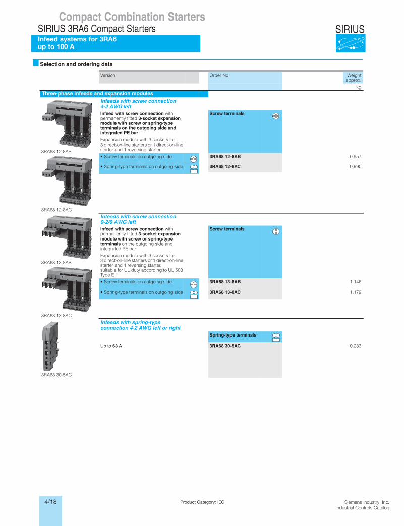
kgThree-phase infeeds and expansion modules
3RA68 12-8AB
3RA68 12-8AC
Infeeds with screw connection4-2 AWG leftInfeed with screw connection with permanently fitted 3-socket expansionmodule with screw or spring-typeterminals on the outgoing side andintegrated PE barExpansion module with 3 sockets for 3 direct-on-line starters or 1 direct-on-line starter and 1 reversing starter
Screw terminals
• Screw terminals on outgoing side 3RA68 12-8AB 0.957
• Spring-type terminals on outgoing side 3RA68 12-8AC 0.990
3RA68 13-8AB
3RA68 13-8AC
Infeeds with screw connection0-2/0 AWG leftInfeed with screw connection with permanently fitted 3-socket expansionmodule with screw or spring-typeterminals on the outgoing side and integrated PE bar
Expansion module with 3 sockets for 3 direct-on-line starters or 1 direct-on-line starter and 1 reversing starter, suitable for UL duty according to UL 508 Type E
Screw terminals
• Screw terminals on outgoing side 3RA68 13-8AB 1.146
• Spring-type terminals on outgoing side 3RA68 13-8AC 1.179
3RA68 30-5AC
Infeeds with spring-typeconnection 4-2 AWG left or right
Spring-type terminals
Up to 63 A 3RA68 30-5AC 0.283
LV1N_06_04.fm Page 54 Tuesday, September 24, 2013 11:55 AM
Compact Combination StartersSIRIUS 3RA6 Compact StartersInfeed systems for 3RA6 up to 100 A
4/19Siemens Industry, Inc.Industrial Controls Catalog
SIRIUS
Product Category: IEC
Compact Combination StartersSIRIUS 3RA6 Compact Starters
Infeed systems for 3RA6
For Operation in the Control CabinetSIRIUS 3RA6 Compact Starters
Infeed systems for 3RA6
6/55SIRIUS Innovations Supplement 2012Illustrations are approximate
6
Version Order No. Weightapprox.
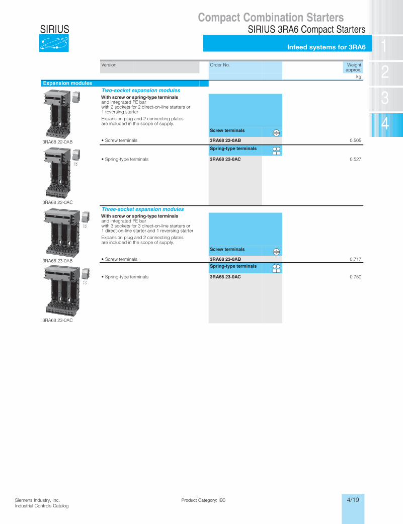
kgExpansion modules
3RA68 22-0AB
Two-socket expansion modulesWith screw or spring-type terminalsand integrated PE barwith 2 sockets for 2 direct-on-line starters or 1 reversing starter
Expansion plug and 2 connecting plates are included in the scope of supply.
Screw terminals
• Screw terminals 3RA68 22-0AB 0.505
3RA68 22-0AC
Spring-type terminals
• Spring-type terminals 3RA68 22-0AC 0.527
3RA68 23-0AB
3RA68 23-0AC
Three-socket expansion modulesWith screw or spring-type terminalsand integrated PE barwith 3 sockets for 3 direct-on-line starters or 1 direct-on-line starter and 1 reversing starter
Expansion plug and 2 connecting plates are included in the scope of supply.
Screw terminals
• Screw terminals 3RA68 23-0AB 0.717
Spring-type terminals
• Spring-type terminals 3RA68 23-0AC 0.750
LV1N_06_04.fm Page 55 Tuesday, September 24, 2013 11:55 AM
4/20 Siemens Industry, Inc.Industrial Controls Catalog
SIRIUS
Product Category: IEC
Compact Combination StartersSIRIUS 3RA6 Compact Starters
Infeed systems for 3RA6
For Operation in the Control CabinetSIRIUS 3RA6 Compact Starters
Infeed systems for 3RA6
6/56 SIRIUS Innovations Supplement 2012 Illustrations are approximate
6
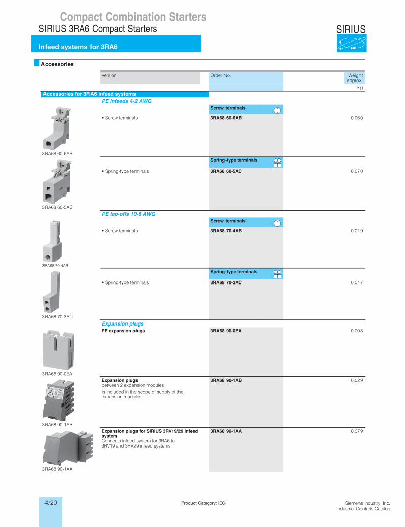
Accessories Version Order No. Weight
approx.
kgAccessories for 3RA6 infeed systems
PE infeeds 4-2 AWG
3RA68 60-6AB
Screw terminals
• Screw terminals 3RA68 60-6AB 0.060
3RA68 60-5AC
Spring-type terminals
• Spring-type terminals 3RA68 60-5AC 0.070
PE tap-offs 10-8 AWG
3RA68 70-4AB
Screw terminals
• Screw terminals 3RA68 70-4AB 0.019
3RA68 70-3AC
Spring-type terminals
• Spring-type terminals 3RA68 70-3AC 0.017
Expansion plugs
3RA68 90-0EA
PE expansion plugs 3RA68 90-0EA 0.008
3RA68 90-1AB
Expansion plugsbetween 2 expansion modules
Is included in the scope of supply of the expansion modules.
3RA68 90-1AB 0.029
3RA68 90-1AA
Expansion plugs for SIRIUS 3RV19/29 infeedsystemConnects infeed system for 3RA6 to 3RV19 and 3RV29 infeed systems
3RA68 90-1AA 0.079
LV1N_06_04.fm Page 56 Tuesday, September 24, 2013 11:55 AM
4/21Siemens Industry, Inc.Industrial Controls Catalog
SIRIUS
Product Category: IEC
Siemens / Industrial Controls Previous folio: LV1 6/71
Compact Combination StartersSIRIUS 3RA6 Compact Starters
Infeed systems for 3RA6
For Operation in the Control CabinetSIRIUS 3RA6 Compact Starters
Infeed systems for 3RA6
6/57SIRIUS Innovations Supplement 2012Illustrations are approximate
6
Version Order No. Weightapprox.
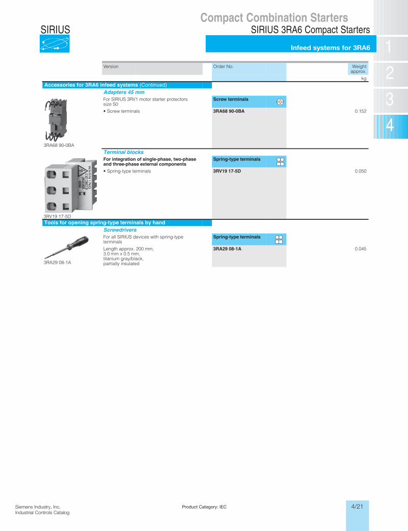
kgAccessories for 3RA6 infeed systems (Continued)
Adapters 45 mm
3RA68 90-0BA
For SIRIUS 3RV1 motor starter protectors size S0
Screw terminals
• Screw terminals 3RA68 90-0BA 0.152
Terminal blocks
3RV19 17-5D
For integration of single-phase, two-phaseand three-phase external components
Spring-type terminals
• Spring-type terminals 3RV19 17-5D 0.050
Tools for opening spring-type terminals by hand
Screwdrivers
3RA29 08-1A
For all SIRIUS devices with spring-type terminals
Spring-type terminals
Length approx. 200 mm, 3.0 mm x 0.5 mm, titanium gray/black, partially insulated
3RA29 08-1A 0.045
LV1N_06_04.fm Page 57 Tuesday, September 24, 2013 11:55 AM
4/22 Siemens Industry, Inc.Industrial Controls Catalog
SIRIUS
Product Category: IEC
Siemens / Industrial Controls Previous folio: LV1 6/63
Compact Combination StartersSIRIUS 3RA6 Compact Starters
General data
For Operation in the Control CabinetSIRIUS 3RA6 Compact Starters
General data
6/35SIRIUS Innovations Supplement 2012
6
More information
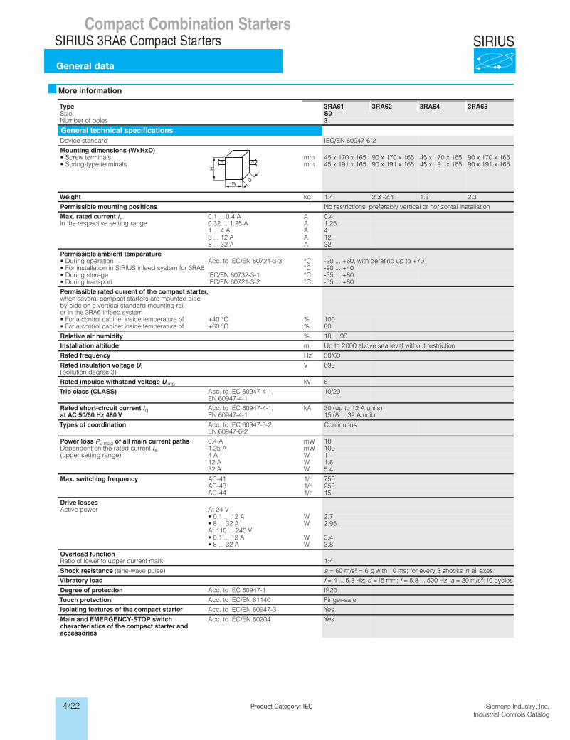
Type 3RA61 3RA62 3RA64 3RA65Size S0
selop fo rebmuN 3General technical specifications
Device standard IEC/EN 60947-6-2
Mounting dimensions (WxHxD)mmslanimret wercS• 45 x 170 x 165 90 x 170 x 165 45 x 170 x 165 90 x 170 x 165mmslanimret epyt-gnirpS• 45 x 191 x 165 90 x 191 x 165 45 x 191 x 165 90 x 191 x 165
Weight kg 1.4 2.3 -2.4 1.3 2.3
Permissible mounting positions No restrictions, preferably vertical or horizontal installation
Max. rated current Iein the respective setting range
0.1 ... 0.4 A A 0.40.32 ... 1.25 A A 1.25
AA 4 ... 1 4AA 21 ... 3 12AA 23 ... 8 32
Permissible ambient temperatureC°3-3-12706 NE/CEI ot .ccAnoitarepo gniruD• -20 ... +60, with derating up to +70C°6AR3 rof metsys deefni SUIRIS ni noitallatsni roF• -20 ... +40 C°1-3-23706 NE/CEIegarots gniruD• -55 ... +80C°2-3-12706 NE/CEItropsnart gniruD• -55 ... +80
Permissible rated current of the compact starter,when several compact starters are mounted side-by-side on a vertical standard mounting rail or in the 3RA6 infeed system• For a control cabinet inside temperature of %C° 04+ 100• For a control cabinet inside temperature of %C° 06+ 80
Relative air humidity % 10 ... 90
Installation altitude m Up to 2 000 above sea level without restriction
Rated frequency Hz 50/60
Rated insulation voltage Ui (pollution degree 3)
V 690
Rated impulse withstand voltage Uimp kV 6
Trip class (CLASS) Acc. to IEC 60947-4-1, EN 60947-4-1
10/20
Rated short-circuit current Iq at AC 50/60 Hz 480 V
Acc. to IEC 60947-4-1, EN 60947-4-1
kA 30 (up to 12 A units)15 (8 ... 32 A unit)
Types of coordination Acc. to IEC 60947-6-2, EN 60947-6-2
Continuous
Power loss Pv max of all main current pathsDependent on the rated current Ie(upper setting range)
WmA 4.0 10WmA 52.1 100
WA 4 1WA 21 1.8WA 23 5.4
Max. switching frequency h/114-CA 750h/134-CA 250h/144-CA 15
Drive lossesV 42 tArewop evitcA
• 0.1 ... 12 A W 2.7WA 23 ... 8• 2.95
At 110 ... 240 V• 0.1 ... 12 A W 3.4
WA 23 ... 8• 3.8
Overload functionRatio of lower to upper current mark 1:4
Shock resistance (sine-wave pulse) a = 60 m/s² = 6 g with 10 ms; for every 3 shocks in all axes
Vibratory load f = 4 ... 5.8 Hz; d =15 mm; f = 5.8 ... 500 Hz; a = 20 m/s2;10 cycles
Degree of protection Acc. to IEC 60947-1 IP20
Touch protection Acc. to IEC/EN 61140 Finger-safe
Isolating features of the compact starter Acc. to IEC/EN 60947-3 Yes
Main and EMERGENCY-STOP switchcharacteristics of the compact starter andaccessories
Acc. to IEC/EN 60204 Yes
W
H
D
LV1N_06_03.fm Page 35 Tuesday, September 24, 2013 11:35 AM
4/23Siemens Industry, Inc.Industrial Controls Catalog
SIRIUSCompact Combination Starters
SIRIUS 3RA6 Compact Starters
General data
For Operation in the Control CabinetSIRIUS 3RA6 Compact Starters
General data
6/36 SIRIUS Innovations Supplement 2012
6
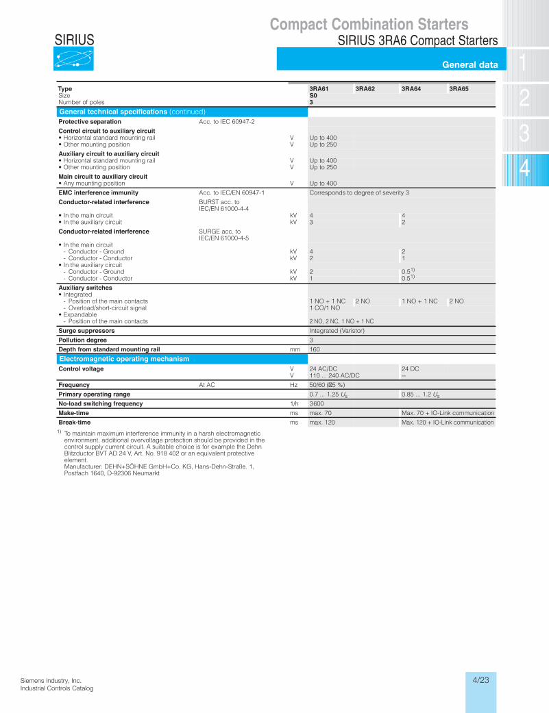
1) To maintain maximum interference immunity in a harsh electromagnetic environment, additional overvoltage protection should be provided in the control supply current circuit. A suitable choice is for example the Dehn Blitzductor BVT AD 24 V, Art. No. 918 402 or an equivalent protective element.Manufacturer: DEHN+SÖHNE GmbH+Co. KG, Hans-Dehn-Straße. 1, Postfach 1640, D-92306 Neumarkt
Type 3RA61 3RA62 3RA64 3RA65Size S0
selop fo rebmuN 3General technical specifications (continued)Protective separation Acc. to IEC 60947-2
Control circuit to auxiliary circuitVliar gnitnuom dradnats latnoziroH• Up to 400Vnoitisop gnitnuom rehtO• Up to 250
Auxiliary circuit to auxiliary circuitVliar gnitnuom dradnats latnoziroH• Up to 400Vnoitisop gnitnuom rehtO• Up to 250
Main circuit to auxiliary circuitVnoitisop gnitnuom ynA• Up to 400
EMC interference immunity Acc. to IEC/EN 60947-1 Corresponds to degree of severity 3
Conductor-related interference BURST acc. to IEC/EN 61000-4-4
Vktiucric niam eht nI• 4 4Vktiucric yrailixua eht nI• 3 2
Conductor-related interference SURGE acc. to IEC/EN 61000-4-5
• In the main circuitVkdnuorG - rotcudnoC- 4 2VkrotcudnoC - rotcudnoC- 2 1
• In the auxiliary circuitVkdnuorG - rotcudnoC- 2 0.51) VkrotcudnoC - rotcudnoC- 1 0.51)
Auxiliary switches• Integrated
- Position of the main contacts 1 NO + 1 NC 2 NO 1 NO + 1 NC 2 NO- Overload/short-circuit signal 1 CO/1 NO
• Expandable- Position of the main contacts 2 NO, 2 NC, 1 NO + 1 NC
Surge suppressors Integrated (Varistor)
Pollution degree 3
Depth from standard mounting rail mm 160
Electromagnetic operating mechanism
Control voltage V 24 AC/DC 24 DCV 110 ... 240 AC/DC --
Frequency zHCA tA 50/60 (�5 %)
Primary operating range 0.7 ... 1.25 Us 0.85 ... 1.2 Us
No-load switching frequency 1/h 3 600
Make-time ms max. 70 Max. 70 + IO-Link communication
Break-time ms max. 120 Max. 120 + IO-Link communication
LV1N_06_03.fm Page 36 Tuesday, September 24, 2013 11:35 AM
4/24 Siemens Industry, Inc.Industrial Controls Catalog
SIRIUS
Product Category: IEC
Compact Combination StartersSIRIUS 3RA6 Compact Starters
General data
For Operation in the Control CabinetSIRIUS 3RA6 Compact Starters
General data
6/37SIRIUS Innovations Supplement 2012
6
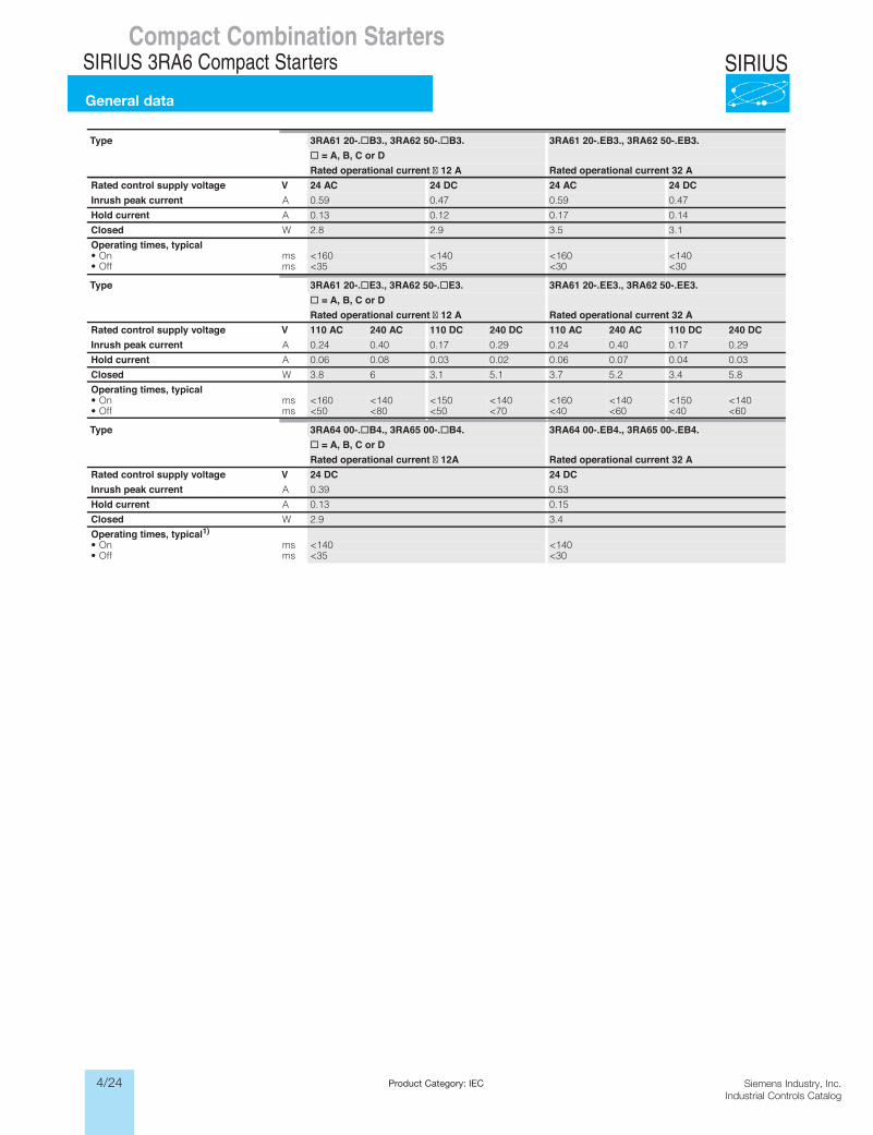
Type 3RA61 20-.@B3., 3RA62 50-.@B3. 3RA61 20-.EB3., 3RA62 50-.EB3. @ = A, B, C or D
Rated operational current � 12 A Rated operational current 32 ARated control supply voltage V 24 AC 24 DC 24 AC 24 DCInrush peak current A 0.59 0.47 0.59 0.47
Hold current A 0.13 0.12 0.17 0.14
Closed W 2.8 2.9 3.5 3.1
Operating times, typicalsmnO• <160 <140 <160 <140smffO• <35 <35 <30 <30
Type 3RA61 20-.@E3., 3RA62 50-.@E3. 3RA61 20-.EE3., 3RA62 50-.EE3. @ = A, B, C or D
Rated operational current � 12 A Rated operational current 32 ARated control supply voltage V 110 AC 240 AC 110 DC 240 DC 110 AC 240 AC 110 DC 240 DCInrush peak current A 0.24 0.40 0.17 0.29 0.24 0.40 0.17 0.29
Hold current A 0.06 0.08 0.03 0.02 0.06 0.07 0.04 0.03
Closed W 3.8 6 3.1 5.1 3.7 5.2 3.4 5.8
Operating times, typicalsmnO• <160 <140 <150 <140 <160 <140 <150 <140smffO• <50 <80 <50 <70 <40 <60 <40 <60
Type 3RA64 00-.@B4., 3RA65 00-.@B4. 3RA64 00-.EB4., 3RA65 00-.EB4. @ = A, B, C or D
Rated operational current � 12A Rated operational current 32 ARated control supply voltage V 24 DC 24 DCInrush peak current A 0.39 0.53
Hold current A 0.13 0.15
Closed W 2.9 3.4
Operating times, typical1)smnO• <140 <140smffO• <35 <30
LV1N_06_03.fm Page 37 Tuesday, September 24, 2013 11:35 AM
4/25Siemens Industry, Inc.Industrial Controls Catalog
SIRIUSCompact Combination Starters
SIRIUS 3RA6 Compact Starters
General data
For Operation in the Control CabinetSIRIUS 3RA6 Compact Starters
General data
6/38 SIRIUS Innovations Supplement 2012
6
Type 3RA61 3RA62 3RA64 3RA65Size S0
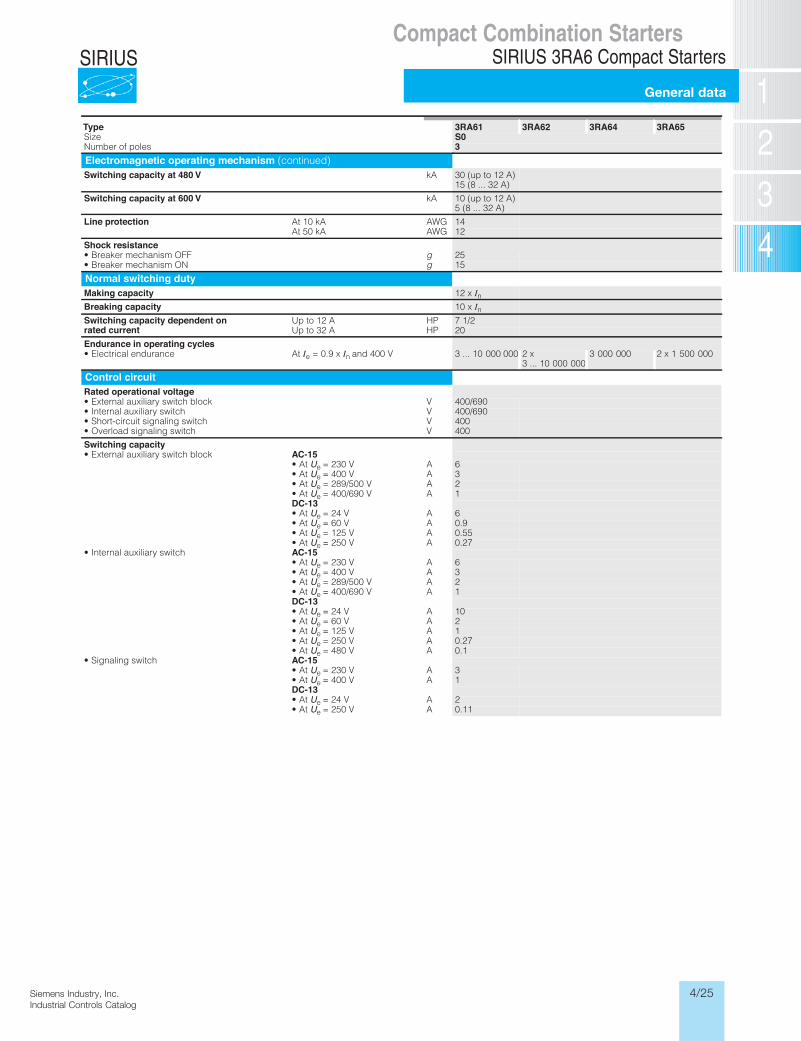
selop fo rebmuN 3Electromagnetic operating mechanism (continued)Switching capacity at 480 V kA 30 (up to 12 A)
15 (8 ... 32 A)
Switching capacity at 600 V kA 10 (up to 12 A)5 (8 ... 32 A)
Line protection GWAAk 01 tA 14GWAAk 05 tA 12
Shock resistance• Breaker mechanism OFF g 25• Breaker mechanism ON g 15
Normal switching dutyMaking capacity 12 x InBreaking capacity 10 x InSwitching capacity dependent onrated current
PHA 21 ot pU 7 1/2 PHA 23 ot pU 20
Endurance in operating cycles tAecnarudne lacirtcelE• Ie = 0.9 x In and 400 V 3 ... 10 000 000 2 x
3 ... 10 000 0003 000 000 2 x 1 500 000
Control circuitRated operational voltage
Vkcolb hctiws yrailixua lanretxE• 400/690Vhctiws yrailixua lanretnI• 400/690Vhctiws gnilangis tiucric-trohS• 400Vhctiws gnilangis daolrevO• 400
Switching capacity• External auxiliary switch block AC-15
• At Ue = 230 V A 6• At Ue = 400 V A 3• At Ue = 289/500 V A 2• At Ue = 400/690 V A 1DC-13• At Ue = 24 V A 6• At Ue = 60 V A 0.9• At Ue = 125 V A 0.55• At Ue = 250 V A 0.27
• Internal auxiliary switch AC-15• At Ue = 230 V A 6• At Ue = 400 V A 3• At Ue = 289/500 V A 2• At Ue = 400/690 V A 1DC-13• At Ue = 24 V A 10• At Ue = 60 V A 2• At Ue = 125 V A 1• At Ue = 250 V A 0.27• At Ue = 480 V A 0.1
• Signaling switch AC-15• At Ue = 230 V A 3• At Ue = 400 V A 1DC-13• At Ue = 24 V A 2• At Ue = 250 V A 0.11
LV1N_06_03.fm Page 38 Tuesday, September 24, 2013 11:35 AM
4/26 Siemens Industry, Inc.Industrial Controls Catalog
SIRIUS
Product Category: IEC
Siemens / Industrial Controls Previous folio: LV1 6/64
Compact Combination StartersSIRIUS 3RA6 Compact Starters
General data
For Operation in the Control CabinetSIRIUS 3RA6 Compact Starters
General data
6/39SIRIUS Innovations Supplement 2012
6
Type 3RA61 3RA62 3RA64 3RA65Size S0
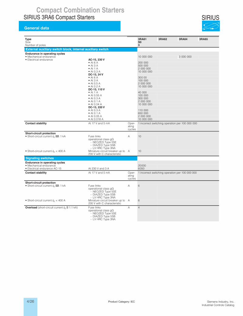
selop fo rebmuN 3External auxiliary switch block, internal auxiliary switchEndurance in operating cycles• Mechanical endurance 10 000 000 3 000 000• Electrical endurance AC-15, 230 V
• At 6 A 200 000• At 3 A 500 000• At 1 A 2 000 000• At 0.3 A 10 000 000DC-13, 24 V• At 6 A 30 0 00• At 3 A 100 000• At 0.5 A 2 000 000• At 0.2 A 10 000 000DC-13, 110 V• At 1 A 40 000• At 0.55 A 100 000• At 0.3 A 300 000• At 0.1 A 2 000 000• At 0.04 A 10 000 000DC-13, 220 V• At 0.3 A 110 000• At 0.1 A 650 000• At 0.05 A 2 000 000• At 0.018 A 10 000 000
Contact stability At 17 V and 5 mA Oper-atingcycles
1 incorrect switching operation per 100 000 000
Short-circuit protection• Short-circuit current IK ��1.1 kA Fuse links
operational class gG- NEOZED Type 5SE- DIAZED Type 5SB- LV HRC Type 3NA
A 10
• Short-circuit current IK < 400 A Miniature circuit breaker up to 230 V with C characteristic
A 10
Signaling switchesEndurance in operating cycles• Mechanical endurance 20 000• Electrical endurance AC-15 At 230 V and 3 A 6 050
Contact stability At 17 V and 5 mA Oper-atingcycles
1 incorrect switching operation per 100 000 000
Short-circuit protection• Short-circuit current IK ��1.1 kA Fuse links
operational class gG- NEOZED Type 5SE- DIAZED Type 5SB- LV HRC Type 3NA
A 6
• Short-circuit current IK < 400 A Miniature circuit breaker up to 230 V with C characteristic
A 6
Overload (short-circuit current IK � 1.1 kA) Fuse links operational class gG
- NEOZED Type 5SE- DIAZED Type 5SB- LV HRC Type 3NA
A 4
LV1N_06_03.fm Page 39 Tuesday, September 24, 2013 11:35 AM
4/27Siemens Industry, Inc.Industrial Controls Catalog
SIRIUS
Siemens / Industrial Controls Previous folio: IC2010 4-27
Compact Combination StartersSIRIUS 3RA6 Compact Starters
3RA6 up to 32 A
Technical data
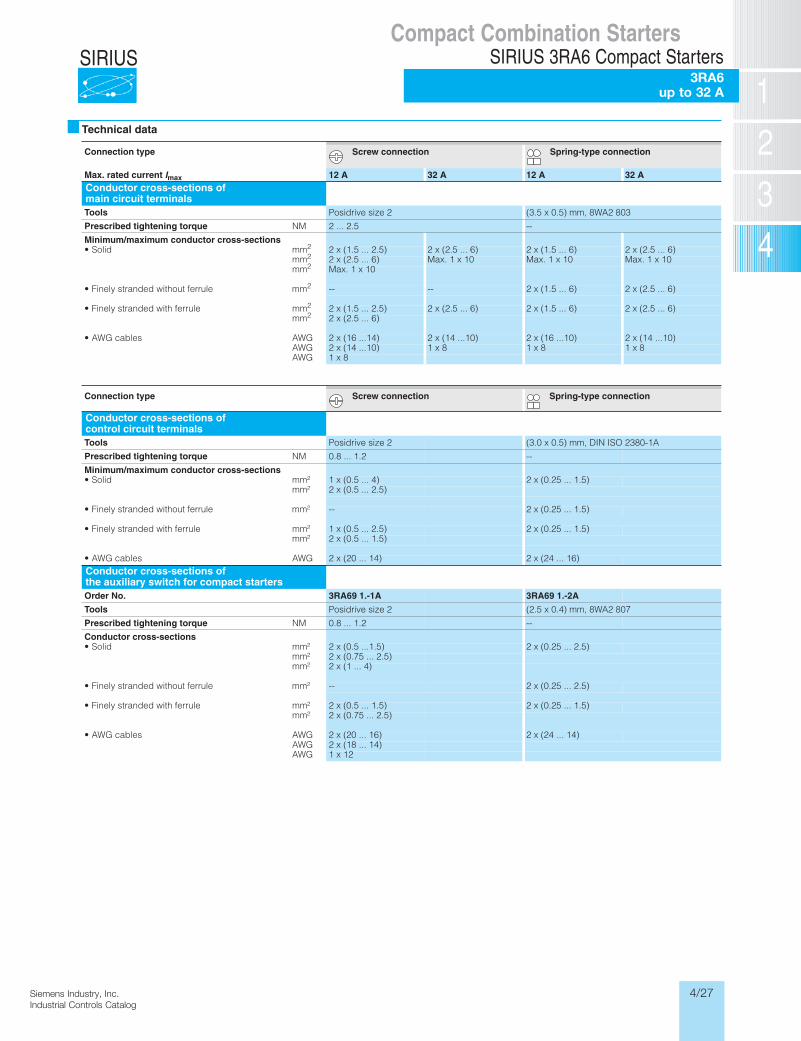
Connection type Screw connection Spring-type connection
Max. rated current Imax 12 A 32 A 12 A 32 AConductor cross-sections of main circuit terminalsTools Posidrive size 2 (3.5 x 0.5) mm, 8WA2 803
Prescribed tightening torque NM 2 ... 2.5 --
Minimum/maximum conductor cross-sectionsmmdiloS• 2 2 x (1.5 ... 2.5) 2 x (2.5 ... 6) 2 x (1.5 ... 6) 2 x (2.5 ... 6)
mm2 2 x (2.5 ... 6) Max. 1 x 10 Max. 1 x 10 Max. 1 x 10mm2 Max. 1 x 10
• Finely stranded without ferrule mm2 -- -- 2 x (1.5 ... 6) 2 x (2.5 ... 6)
mmelurref htiw dednarts yleniF• 2 2 x (1.5 ... 2.5) 2 x (2.5 ... 6) 2 x (1.5 ... 6) 2 x (2.5 ... 6)mm2 2 x (2.5 ... 6)
GWAselbac GWA• 2 x (16 ...14) 2 x (14 ...10) 2 x (16 ...10) 2 x (14 ...10)AWG 2 x (14 ...10) 1 x 8 1 x 8 1 x 8AWG 1 x 8
Connection type Screw connection Spring-type connection
Conductor cross-sections of control circuit terminals Tools Posidrive size 2 (3.0 x 0.5) mm, DIN ISO 2380-1A
Prescribed tightening torque NM 0.8 ... 1.2 --
Minimum/maximum conductor cross-sections²mmdiloS• 1 x (0.5 ... 4) 2 x (0.25 ... 1.5)
mm² 2 x (0.5 ... 2.5)
• Finely stranded without ferrule mm² -- 2 x (0.25 ... 1.5)
²mmelurref htiw dednarts yleniF• 1 x (0.5 ... 2.5) 2 x (0.25 ... 1.5)mm² 2 x (0.5 ... 1.5)
GWAselbac GWA• 2 x (20 ... 14) 2 x (24 ... 16)Conductor cross-sections of the auxiliary switch for compact startersOrder No. 3RA69 1.-1A 3RA69 1.-2A
Tools Posidrive size 2 (2.5 x 0.4) mm, 8WA2 807
Prescribed tightening torque NM 0.8 ... 1.2 --
Conductor cross-sections²mmdiloS• 2 x (0.5 ...1.5) 2 x (0.25 ... 2.5)
mm² 2 x (0.75 ... 2.5)mm² 2 x (1 ... 4)
• Finely stranded without ferrule mm² -- 2 x (0.25 ... 2.5)
²mmelurref htiw dednarts yleniF• 2 x (0.5 ... 1.5) 2 x (0.25 ... 1.5)mm² 2 x (0.75 ... 2.5)
GWAselbac GWA• 2 x (20 ... 16) 2 x (24 ... 14)AWG 2 x (18 ... 14)AWG 1 x 12
4/28 Siemens Industry, Inc.Industrial Controls Catalog
SIRIUSCompact Combination Starters
SIRIUS 3RA6 Compact Starters3RA6 up to 32A
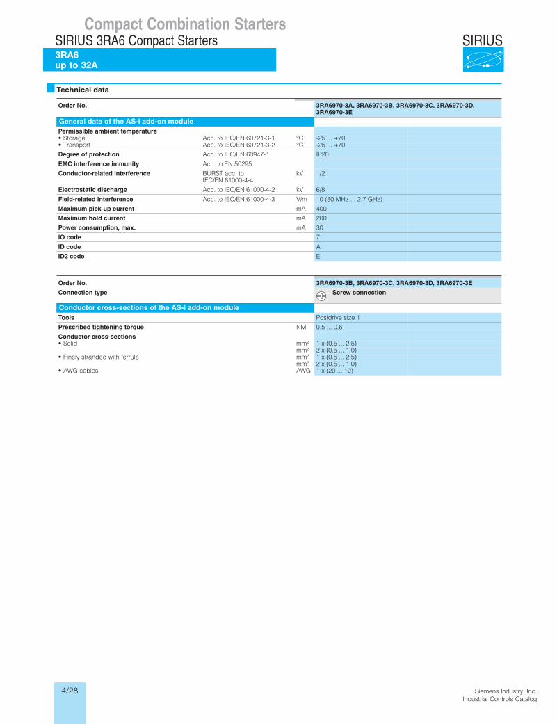
Order No. 3RA6970-3A, 3RA6970-3B, 3RA6970-3C, 3RA6970-3D, 3RA6970-3E
General data of the AS-i add-on modulePermissible ambient temperature
C°1-3-12706 NE/CEI ot .ccAegarotS• -25 ... +70C°2-3-12706 NE/CEI ot .ccAtropsnarT• -25 ... +70
Degree of protection Acc. to IEC/EN 60947-1 IP20
EMC interference immunity Acc. to EN 50295
Conductor-related interference BURST acc. to IEC/EN 61000-4-4
kV 1/2
Electrostatic discharge Acc. to IEC/EN 61000-4-2 kV 6/8
Field-related interference Acc. to IEC/EN 61000-4-3 V/m 10 (80 MHz ... 2.7 GHz)
Maximum pick-up current mA 400
Maximum hold current mA 200
Power consumption, max. mA 30
IO code 7
ID code A
ID2 code E
Order No. 3RA6970-3B, 3RA6970-3C, 3RA6970-3D, 3RA6970-3E
Connection type Screw connection
Conductor cross-sections of the AS-i add-on moduleTools Posidrive size 1
Prescribed tightening torque NM 0.5 ... 0.6
Conductor cross-sections• Solid mm² 1 x (0.5 ... 2.5)
mm² 2 x (0.5 ... 1.0)²mm elurref htiw dednarts yleniF• 1 x (0.5 ... 2.5)
mm² 2 x (0.5 ... 1.0)GWAselbac GWA• 1 x (20 ... 12)
Technical data
4/29Siemens Industry, Inc.Industrial Controls Catalog
SIRIUSCompact Combination Starters
SIRIUS 3RA6 Compact StartersInfeed systems for 3RA6
up to 100 A
Technical data
1) To prevent the possibility of short-circuits, the cables on the terminal block must be installed so that they are short-circuit resistant according to EN 60439-1 Section 7.5.5.1.2.
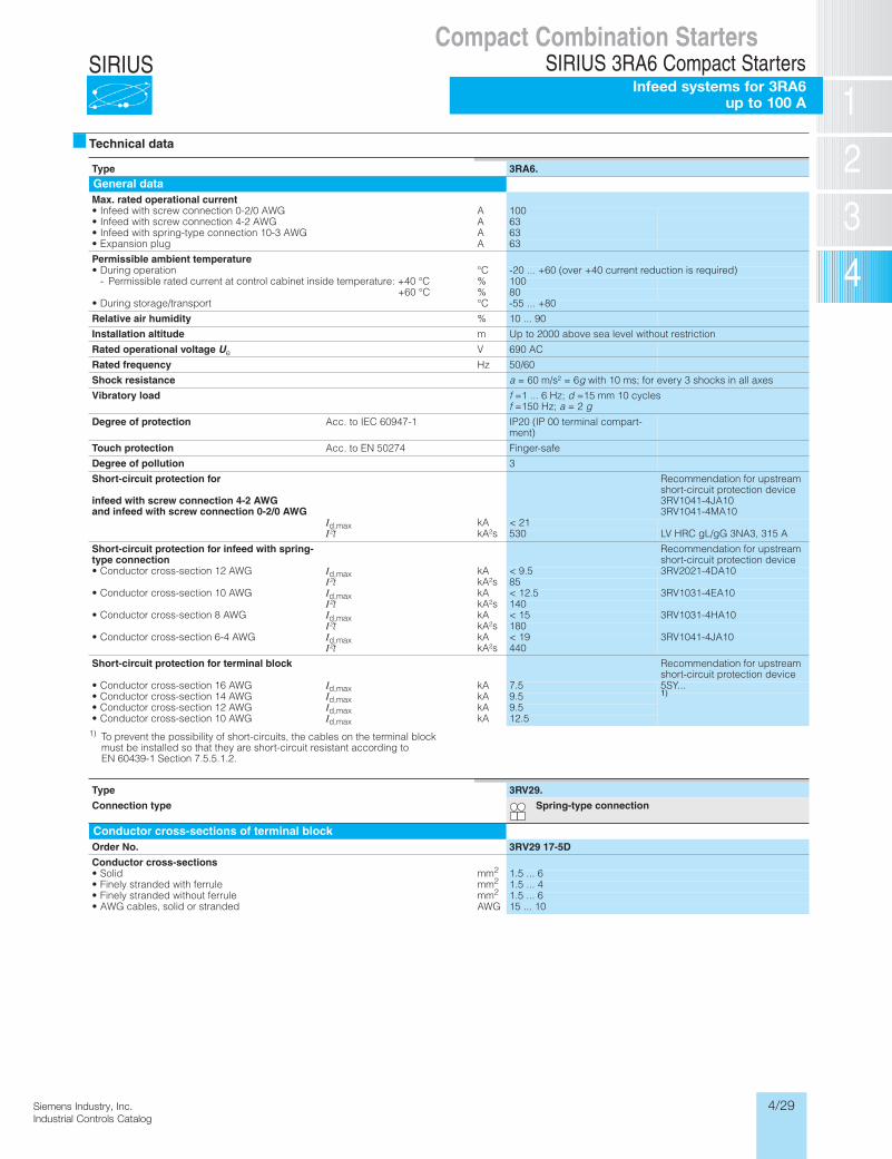
Type 3RA6.
General dataMax. rated operational current• Infeed with screw AGWA 0/2-0 noitcennoc 100• Infeed with screw AGWA 2-4 noitcennoc 63• Infeed with spring-typ AGWA 3-01 noitcennoc e 63
Agulp noisnapxE• 63
Permissible ambient temperatureC°noitarepo gniruD• -20 ... +60 (over +40 current reduction is required)
- Permissible rated current at control cabinet inside temperature: +40 °C % 100+60 °C % 80
C°tropsnart/egarots gniruD• -55 ... +80
Relative air humidity % 10 ... 90
Installation altitude m Up to 2000 above sea level without restriction
Rated operational voltage Ue V 690 AC
Rated frequency Hz 50/60
Shock resistance a = 60 m/s² = 6g with 10 ms; for every 3 shocks in all axes
Vibratory load f =1 ... 6 Hz; d =15 mm 10 cyclesf =150 Hz; a = 2 g
Degree of protection Acc. to IEC 60947-1 IP20 (IP 00 terminal compart-ment)
Touch protection Acc. to EN 50274 Finger-safe
Degree of pollution 3
Short-circuit protection for
infeed with screw connection 4-2 AWGand infeed with screw connection 0-2/0 AWG
Recommendation for upstream short-circuit protection device3RV1041-4JA103RV1041-4MA10
Id,max kA < 21I²t kA²s 530 LV HRC gL/gG 3NA3, 315 A
Short-circuit protection for infeed with spring-type connection
Recommendation for upstream short-circuit protection device
• Conductor cross-section 12 AWG Id,max kA < 9.5 3RV2021-4DA10I²t kA²s 85
• Conductor cross-section 10 AWG Id,max kA < 12.5 3RV1031-4EA10I²t kA²s 140
• Conductor cross-section 8 AWG Id,max kA < 15 3RV1031-4HA10I²t kA²s 180
• Conductor cross-section 6-4 AWG Id,max kA < 19 3RV1041-4JA10I²t kA²s 440
Short-circuit protection for terminal block Recommendation for upstream short-circuit protection device
• Conductor cross-section 16 AWG Id,max kA 7.5 5SY...• Conductor cross-section 14 AWG Id,max kA 9.5 1)
• Conductor cross-section 12 AWG Id,max kA 9.5• Conductor cross-section 10 AWG Id,max kA 12.5
Type 3RV29.
Connection type Spring-type connection
Conductor cross-sections of terminal blockOrder No. 3RV29 17-5D
Conductor cross-sections• Solid mm2 1.5 ... 6
mmelurref htiw dednarts yleniF• 2 1.5 ... 4mmelurref tuohtiw dednarts yleniF• 2 1.5 ... 6
GWAdednarts ro dilos ,selbac GWA• 15 ... 10
4/30 Siemens Industry, Inc.Industrial Controls Catalog
SIRIUS
Siemens / Industrial Controls Previous folio: IC2010 4-30
Compact Combination StartersSIRIUS 3RA6 Compact StartersInfeed systems for 3RA6 up to 100 A
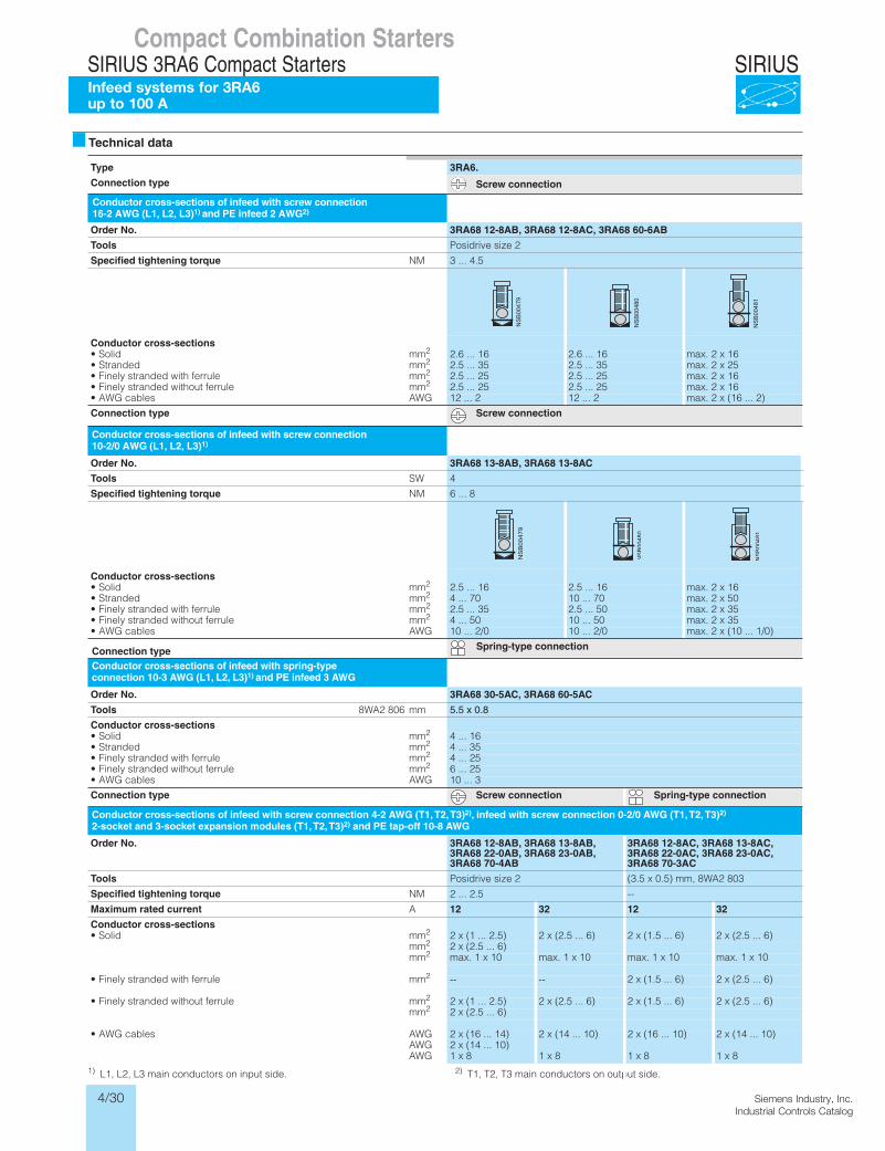
1) L1, L2, L3 main conductors on input side. 2) T1, T2, T3 main conductors on output side.
Type 3RA6.
Connection type Screw connection
Conductor cross-sections of infeed with screw connection16-2 AWG (L1, L2, L3)1) and PE infeed 2 AWG2)
Order No. 3RA68 12-8AB, 3RA68 12-8AC, 3RA68 60-6AB
Tools Posidrive size 2
Specified tightening torque NM 3 ... 4.5
Conductor cross-sectionsmmdiloS• 2 2.6 ... 16 2.6 ... 16 max. 2 x 16mmdednartS• 2 2.5 ... 35 2.5 ... 35 max. 2 x 25mmelurref htiw dednarts yleniF• 2 2.5 ... 25 2.5 ... 25 max. 2 x 16mmelurref tuohtiw dednarts yleniF• 2 2.5 ... 25 2.5 ... 25 max. 2 x 16
GWAselbac GWA• 12 ... 2 12 ... 2 max. 2 x (16 ... 2)
Connection type Screw connection
Conductor cross-sections of infeed with screw connection10-2/0 AWG (L1, L2, L3)1)
Order No. 3RA68 13-8AB, 3RA68 13-8AC
Tools SW 4
Specified tightening torque NM 6 ... 8
Conductor cross-sectionsmmdiloS• 2 2.5 ... 16 2.5 ... 16 max. 2 x 16mmdednartS• 2 4 ... 70 10 ... 70 max. 2 x 50mmelurref htiw dednarts yleniF• 2 2.5 ... 35 2.5 ... 50 max. 2 x 35mmelurref tuohtiw dednarts yleniF• 2 4 ... 50 10 ... 50 max. 2 x 35
GWAselbac GWA• 10 ... 2/0 10 ... 2/0 max. 2 x (10 ... 1/0)
Connection type Spring-type connection
Conductor cross-sections of infeed with spring-typeconnection 10-3 AWG (L1, L2, L3)1) and PE infeed 3 AWG
Order No. 3RA68 30-5AC, 3RA68 60-5AC
Tools 8WA2 806 mm 5.5 x 0.8
Conductor cross-sectionsmmdiloS• 2 4 ... 16mmdednartS• 2 4 ... 35mmelurref htiw dednarts yleniF• 2 4 ... 25mmelurref tuohtiw dednarts yleniF• 2 6 ... 25
GWAselbac GWA• 10 ... 3
Connection type Screw connection Spring-type connection
Order No. 3RA68 12-8AB, 3RA68 13-8AB, 3RA68 22-0AB, 3RA68 23-0AB, 3RA68 70-4AB
3RA68 12-8AC, 3RA68 13-8AC, 3RA68 22-0AC, 3RA68 23-0AC, 3RA68 70-3AC
Tools Posidrive size 2 (3.5 x 0.5) mm, 8WA2 803
Specified tightening torque NM 2 ... 2.5 --
Maximum rated current A 12 32 12 32
Conductor cross-sectionsmmdiloS• 2 2 x (1 ... 2.5) 2 x (2.5 ... 6) 2 x (1.5 ... 6) 2 x (2.5 ... 6)
mm2 2 x (2.5 ... 6)mm2 max. 1 x 10 max. 1 x 10 max. 1 x 10 max. 1 x 10
mmelurref htiw dednarts yleniF• 2 -- -- 2 x (1.5 ... 6) 2 x (2.5 ... 6)
mmelurref tuohtiw dednarts yleniF• 2 2 x (1 ... 2.5) 2 x (2.5 ... 6) 2 x (1.5 ... 6) 2 x (2.5 ... 6)mm2 2 x (2.5 ... 6)
GWAselbac GWA• 2 x (16 ... 14) 2 x (14 ... 10) 2 x (16 ... 10) 2 x (14 ... 10)AWG 2 x (14 ... 10)AWG 1 x 8 1 x 8 1 x 8 1 x 8
Conductor cross-sections of infeed with screw connection 4-2 AWG (T1, T2, T3)2), infeed with screw connection 0-2/0 AWG (T1, T2, T3)2) 2-socket and 3-socket expansion modules (T1, T2, T3)2) and PE tap-off 10-8 AWG
Technical data
4/31Siemens Industry, Inc.Industrial Controls Catalog
SIRIUS
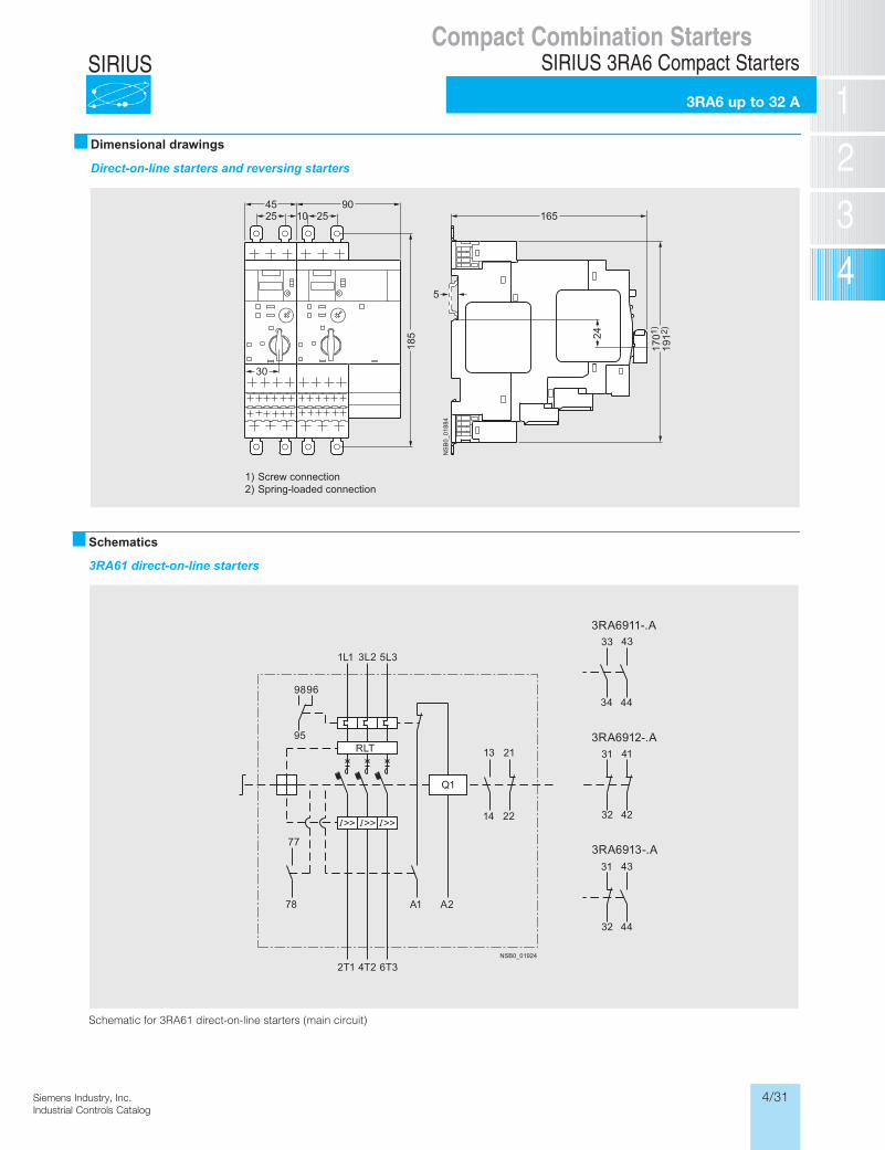
Dimensional drawings
Direct-on-line starters and reversing starters
1701
)
NS
B0_
0188
4
165
24
1912
)
4525
902510
30
185
5
1)2)
Screw connectionSpring-loaded connection
Compact Combination StartersSIRIUS 3RA6 Compact Starters
3RA6 up to 32 A
Schematics
3RA61 direct-on-line starters
Schematic for 3RA61 direct-on-line starters (main circuit)
NSB0_01924
33 43
34 44
31 41
32 42
31 43
32 44
1L1 3L2 5L3
2T1 4T2 6T3
9896
95
77
2A1A87
14 22
13 21RLT
Q1
>> >> >>
3RA6911-.A
3RA6912-.A
3RA6913-.A
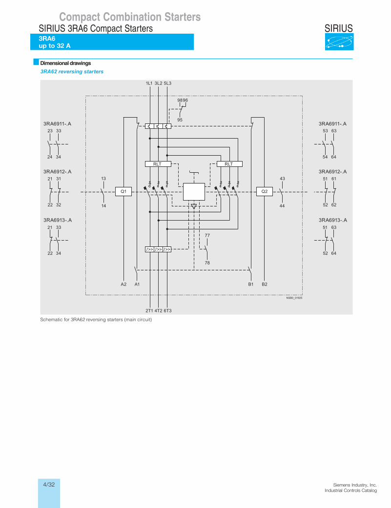
4/32 Siemens Industry, Inc.Industrial Controls Catalog
SIRIUS
Siemens / Industrial Controls Previous folio: LV1 6/67Siemens / Industrial Controls Previous folio: LV1T 6/99
3RA62 reversing starters
Schematic for 3RA62 reversing starters (main circuit)
NSB0_01925
1L1 3L2 5L3
2T1 4T2 6T3
9896
95
77
78
A1A2
14 44
13 43
53 63
54 64
51 61
52 62
51 63
52 64
23 33
24 34
21 31
22 32
21 33
22 34
RLTRLT
Q2Q1
B1 B2
>> >> >>
3RA6911-.A
3RA6912-.A
3RA6913-.A
3RA6911-.A
3RA6912-.A
3RA6913-.A
Dimensional drawings
Compact Combination StartersSIRIUS 3RA6 Compact Starters3RA6 up to 32 A
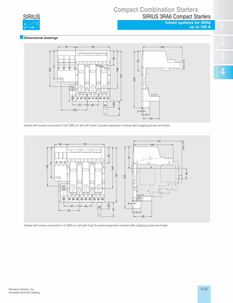
4/33Siemens Industry, Inc.Industrial Controls Catalog
SIRIUS
Siemens / Industrial Controls Previous folio: LV1T 6/107
Compact Combination StartersSIRIUS 3RA6 Compact Starters
Infeed systems for 3RA6 up to 100 A
� Dimensional drawings
Infeed with screw connection 0-2/0 AWG on left with fixed 3-socket expansion module with outgoing screw terminals
Infeed with screw connection 4-2 AWG on left with fixed 3-socket expansion module with outgoing screw terminals
NS
B0_
0192
6
531
65
79
225
155
4557
13570
102
28
111
140
58
6119
7
Ø 4,5
148
NS
B0_
0192
7
5
144176
31
65
79
225 38
4557
76
140 11
1
13545
2858
148
197
61
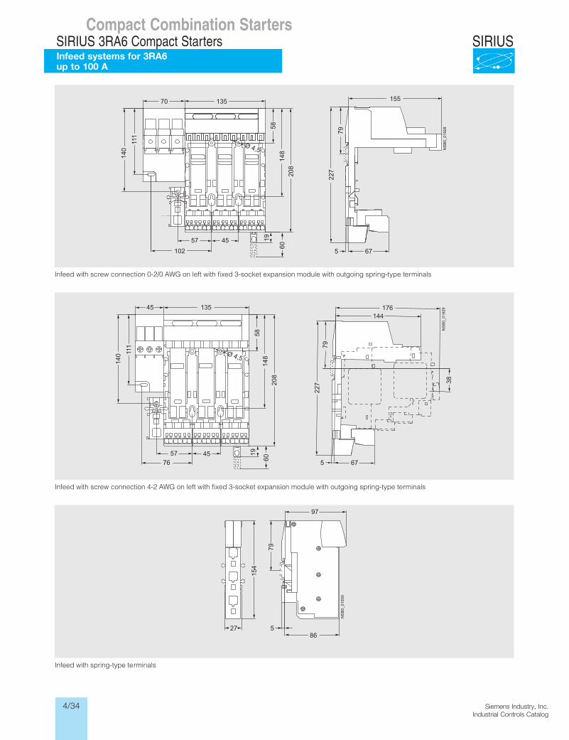
4/34 Siemens Industry, Inc.Industrial Controls Catalog
SIRIUS
Siemens / Industrial Controls Previous folio: IC2010 4/32
Infeed with screw connection 0-2/0 AWG on left with fixed 3-socket expansion module with outgoing spring-type terminals
Infeed with screw connection 4-2 AWG on left with fixed 3-socket expansion module with outgoing spring-type terminals
Infeed with spring-type terminals
NS
B0_
0192
8
70
57 45
135
111
102
140
58
208
19
Ø 4,5
155
67
79
5
227
148
60
NS
B0_
0192
9
140 11
1
13545
5814
8
57 4576
208
19
Ø 4,5
144176
38
79
675
227
60
NS
B0_
0193
0
586
97
27
154
79
Compact Combination StartersSIRIUS 3RA6 Compact StartersInfeed systems for 3RA6 up to 100 A
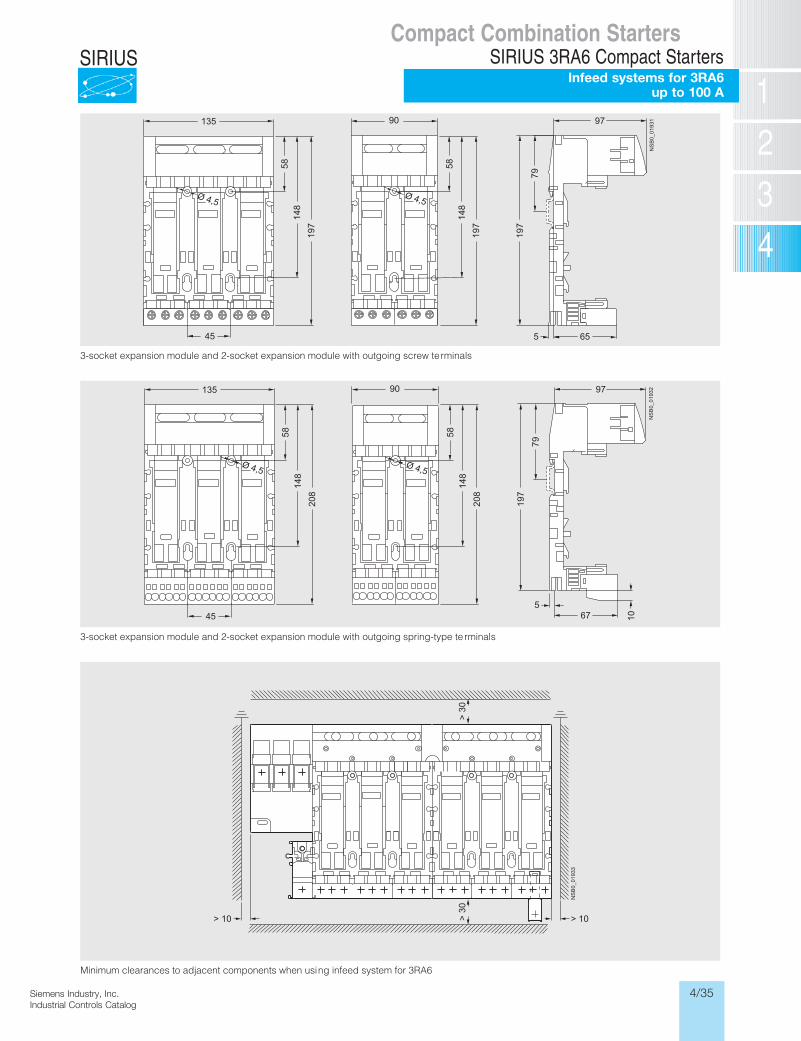
4/35Siemens Industry, Inc.Industrial Controls Catalog
SIRIUS
Siemens / Industrial Controls Previous folio: IC2010 4/33
3-socket expansion module and 2-socket expansion module with outgoing screw terminals
3-socket expansion module and 2-socket expansion module with outgoing spring-type te rminals
Minimum clearances to adjacent components when using infeed system for 3RA6
Ø 4,5
NS
B0_
0193
197
79
5 65
135
58
197
Ø 4,5
90
148
58
197
148
45
197
Ø 4,5
NS
B0_
0193
297
79
567
135
58
208
Ø 4,5
90
148
58
208
148
45
197
10
NS
B0_
0193
3
> 10
> 3
0>
30
> 10
Compact Combination StartersSIRIUS 3RA6 Compact Starters
Infeed systems for 3RA6 up to 100 A
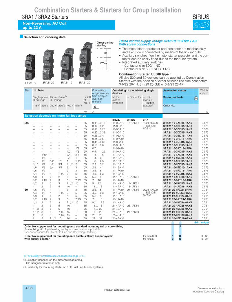
4/36 Siemens Industry, Inc.Industrial Controls Catalog
SIRIUS
Siemens / Industrial Controls Previous folio: LV1N 6-13
Product Category: IEC
Combination Starters & Starters for Group Installation
Non-Reversing, AC Coilup to 22 A
3RA1 / 3RA2 StartersCombination Starters & Starters for Group Installation
SIRIUS 3RA2 Motor Starters3RA21 direct-on-line starters
50/60 Hz 110/120 V AC
6/13SIRIUS Innovations Supplement 2012Illustrations are approximate
6
Selection and ordering dataRated control supply voltage 50/60 Hz 110/120 V ACWith screw connections• The motor starter protector and contactor are mechanically
and electrically connected by means of the link module.• Auxiliary switches1) on the motor starter protector and the con-
tactor can be easily fitted due to the modular system.• Integrated auxiliary switches:
- Contactor size S00: 1 NO; - Contactor size S0: 1 NO + 1 NC
Combination Starter, UL508 Type FAll size S00 and S0 devices can be applied as Combination Starters with the addition of either of these line side connectors: 3RV29 28-1H, 3RV29 25-5EB or 3RV29 28-1K.3RA21 10 3RA21 20 3RA21 10 3RA21 20
Direct-on-linestarting
Size UL Data FLA setting range inverse-time delayed overload release
Consisting of the following singledevices
Assembled starter Weightapprox.
Single-phase HP ratings
Three-phase2) HP ratings
SCCR at 480 V
Motor starter protector
+ Contactor + Link module + Busbar adapter3)
Screw terminals
115 V 230 V 200 V 230 V 460 V 575 V Order No.
kA A kg
Selection depends on motor full load amps3RV20 3RT20 3RA
S00 -- -- -- -- -- -- 65 0.11…0.16 11-0BA10 15-1AK61 1921-1DA00 + 8US1251-5DS10
3RA21 10-0A@15-1AK6 0.575-- -- -- -- -- -- 65 0.14…0.2 11-0BA10 3RA21 10-0B@15-1AK6 0.575-- -- -- -- -- -- 65 0.18…0.25 11-0CA10 3RA21 10-0C@15-1AK6 0.575-- -- -- -- -- -- 65 0.22…0.32 11-0DA10 3RA21 10-0D@15-1AK6 0.575-- -- -- -- -- -- 65 0.28…0.4 11-0EA10 3RA21 10-0E@15-1AK6 0.575-- -- -- -- -- -- 65 0.35…0.5 11-0FA10 3RA21 10-0F@15-1AK6 0.575-- -- -- -- -- -- 65 0.45…0.63 11-0GA10 3RA21 10-0G@15-1AK6 0.575-- -- -- -- -- -- 65 0.55…0.8 11-0HA10 3RA21 10-0H@15-1AK6 0.575-- -- -- -- -- 1/2 65 0.7… 1 11-0JA10 3RA21 10-0J@15-1AK6 0.575-- -- -- -- 1/2 1/2 65 0.9… 1.25 11-0KA10 3RA21 10-0K@15-1AK6 0.575-- 1/10 -- -- 3/4 3/4 65 1.1… 1.6 11-1AA10 3RA21 10-1A@15-1AK6 0.575-- 1/8 -- -- 3/4 1 65 1.4… 2 11-1BA10 3RA21 10-1B@15-1AK6 0.575-- 1/6 1/2 1/2 1 1 1/2 65 1.8… 2.5 11-1CA10 3RA21 10-1C@15-1AK6 0.5751/10 1/4 1/2 3/4 1 1/2 2 65 2.2… 3.2 11-1DA10 3RA21 10-1D@15-1AK6 0.5751/8 1/3 3/4 3/4 2 3 65 2.8… 4 11-1EA10 3RA21 10-1E@15-1AK6 0.5751/6 1/2 1 1 3 3 65 3.5… 5 11-1FA10 3RA21 10-1F@15-1AK6 0.5751/4 1/2 1 1 1/2 3 5 65 4.5… 6.3 11-1GA10 3RA21 10-1G@15-1AK6 0.5751/3 1 2 2 5 5 65 5.5… 8 11-1HA10 16-1AK61 3RA21 10-1H@16-1AK6 0.5751/2 1 1/2 2 3 5 7 1/2 65 7… 10 11-1JA10 3RA21 10-1J@16-1AK6 0.5751/2 2 3 3 7 1/2 10 65 9… 12 11-1KA10 17-1AK61 3RA21 10-1K@17-1AK6 0.5751 2 3 5 10 -- 65 11… 16 11-4AA10 18-1AK61 3RA21 10-4A@18-1AK6 0.575
S0 1/6 1/2 1 1 3 3 65 3.5… 5 11-1FA10 24-1AK60 2921-1AA00 + 8US1251-5NT10
3RA21 20-1F@24-0AK6 0.7611/4 1/2 1 1 1/2 3 5 65 4.5… 6.3 11-1GA10 3RA21 20-1G@24-0AK6 0.7611/3 1 2 2 5 5 65 5.5… 8 11-1HA10 3RA21 20-1H@24-0AK6 0.7611/2 1 1/2 2 3 5 7 1/2 65 7… 10 11-1JA10 3RA21 20-1J@24-0AK6 0.7611/2 2 3 3 7 1/2 10 65 9… 12.5 11-1KA10 3RA21 20-1K@24-0AK6 0.7611 2 3 5 10 -- 65 11… 16 21-4AA10 26-1AK60 3RA21 20-4A@26-0AK6 0.7611 1/2 3 5 5 10 -- 65 14… 20 21-4BA10 3RA21 20-4B@26-0AK6 0.7611 1/2 3 5 7 1/2 15 -- 50 17… 22 21-4CA10 27-1AK60 3RA21 20-4C@27-0AK6 0.7612 3 5 7 1/2 15 -- 50 20… 25 21-4DA10 3RA21 20-4D@27-0AK6 0.7612 5 7 1/2 10 20 -- 50 27… 32 21-4EA10 3RA21 20-4E@27-0AK6 0.761
Add. weightAgnixifwercsroliargnitnuomdradnatsotnognitnuomroftnemelppus.oNredrO
Screw fixing with 1 push-in lug each per motor starter is possible (see "Accessories for Direct-On-Line and Reversing Starters").
Order No. supplement for mounting onto Fastbus 60mm busbar system for size S00 1 D 0.263With busbar adapter for size S0 2 D 0.295
LV1N_06_02.fm Page 13 Tuesday, September 24, 2013 10:52 AM
1) For auxiliary switches see Accessories page 4/44.
2) Selection depends on the motor full load amps. HP ratings for reference only.
3) Used only for mounting starter on 8US Fast Bus busbar systems.
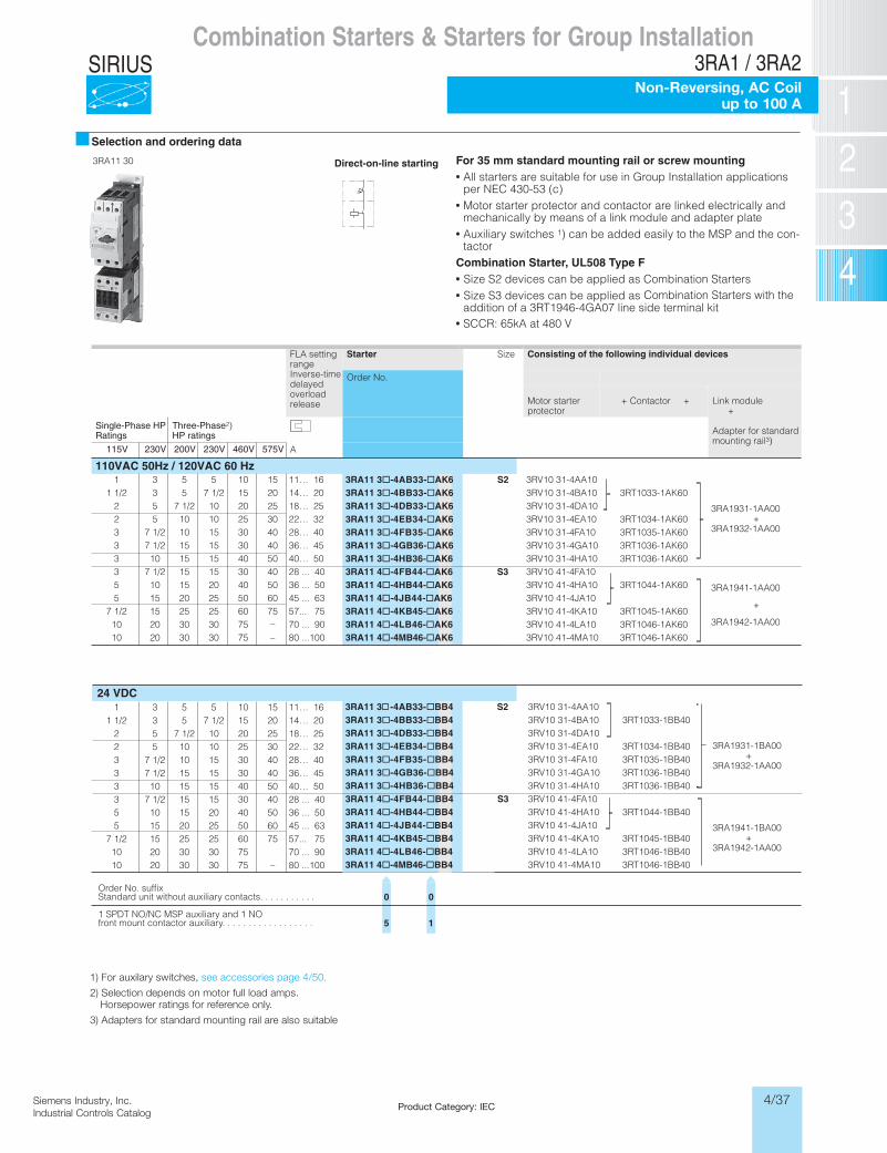
4/37Siemens Industry, Inc.Industrial Controls Catalog
SIRIUS
Product Category: IEC
Selection and ordering data
Direct-on-line starting For 35 mm standard mounting rail or screw mountingAll starters are suitable for use in Group Installation applications per NEC 430-53 (c)Motor starter protector and contactor are linked electrically and mechanically by means of a link module and adapter plateAuxiliary switches 1) can be added easily to the MSP and the con-tactor
Combination Starter, UL508 Type F Size S2 devices can be applied as Combination Starters Size S3 devices can be applied as Combination Starters with the addition of a 3RT1946-4GA07 line side terminal kit
FLA setting rangeInverse-timedelayed overloadrelease
Starter Size Consisting of the following individual devices
Order No.
Motor starterprotector
+ Contactor + Link module+
Adapter for standard mounting rail3)
Single-Phase HP Ratings
Three-Phase2)HP ratings
115V 230V 200V 230V 460V 575V A
110VAC 50Hz / 120VAC 60 Hz3RA11 3@-4AB33-@AK6 S2 3RV10 31-4AA10
3RA1931-1AA00+
3RA1932-1AA00
3RA11 3@-4BB33-@AK6 3RV10 31-4BA10 3RT1033-1AK603RA11 3@-4DB33-@AK6 3RV10 31-4DA103RA11 3@-4EB34-@AK6 3RV10 31-4EA10 3RT1034-1AK603RA11 3@-4FB35-@AK6 3RV10 31-4FA10 3RT1035-1AK603RA11 3@-4GB36-@AK6 3RV10 31-4GA10 3RT1036-1AK603RA11 3@-4HB36-@AK6 3RV10 31-4HA10 3RT1036-1AK603RA11 4@-4FB44-@AK6 S3 3RV10 41-4FA10
3RA1941-1AA00
+
3RA1942-1AA00
3RA11 4@-4HB44-@AK6 3RV10 41-4HA10 3RT1044-1AK603RA11 4@-4JB44-@AK6 3RV10 41-4JA103RA11 4@-4KB45-@AK6 3RV10 41-4KA10 3RT1045-1AK60
10 20 30 30 75 – 3RA11 4@-4LB46-@AK6 3RV10 41-4LA10 3RT1046-1AK60
1 3 5 5 10 15 11… 161 1/2 3 5 7 1/2 15 20 14… 20
2 5 7 1/2 10 20 25 18… 252 5 10 10 25 30 22… 323 7 1/2 10 15 30 40 28… 403 7 1/2 15 15 30 40 36… 453 10 15 15 40 50 40… 503 7 1/2 15 15 30 40 28 ... 405 10 15 20 40 50 36 ... 505 15 20 25 50 60 45 ... 63
7 1/2 15 25 25 60 75 57... 7570 ... 90
10 20 30 30 75 – 80 ...100
10 20 30 30 75
1 3 5 5 10 15 11… 161 1/2 3 5 7 1/2 15 20 14… 20
2 5 7 1/2 10 20 25 18… 252 5 10 10 25 30 22… 323 7 1/2 10 15 30 40 28… 403 7 1/2 15 15 30 40 36… 453 10 15 15 40 50 40… 503 7 1/2 15 15 30 40 28 ... 405 10 15 20 40 50 36 ... 505 15 20 25 50 60 45 ... 63
7 1/2 15 25 25 60 75 57... 7570 ... 90
10 20 30 30 75 – 80 ...100
3RA11 4@-4MB46-@AK6 3RV10 41-4MA10 3RT1046-1AK60
1) For auxilary switches, see accessories page 4/50.
2) Selection depends on motor full load amps. Horse-power ratings for reference only.
3) Adapters for standard mounting rail are also suitable for screw mounting.
3RA11 30
SCCR: 65kA at 480 V
24 VDC3RA11 3 -4AB33-@BB4 S2 3RV10 31-4AA10
3RA1931-1BA00+
3RA1932-1AA00
3RA11 3@-4BB33-@BB4 3RV10 31-4BA10 3RT1033-1BB403RA11 3@-4DB33-@BB4 3RV10 31-4DA103RA11 3@-4EB34-@BB4 3RV10 31-4EA10 3RT1034-1BB403RA11 3@-4FB35-@BB4 3RV10 31-4FA10 3RT1035-1BB403RA11 3@-4GB36-@BB4 3RV10 31-4GA10 3RT1036-1BB403RA11 3@-4HB36-@BB4 3RV10 31-4HA10 3RT1036-1BB403RA11 4@-4FB44-@BB4 S3 3RV10 41-4FA10
3RA1941-1BA00+
3RA1942-1AA00
3RA11 4@-4HB44-@BB4 3RV10 41-4HA10 3RT1044-1BB403RA11 4@-4JB44-@BB4 3RV10 41-4JA103RA11 4@-4KB45-@BB4 3RV10 41-4KA10 3RT1045-1BB403RA11 4@-4LB46-@BB4 3RV10 41-4LA10 3RT1046-1BB403RA11 4@-4MB46-@BB4 3RV10 41-4MA10 3RT1046-1BB40
Order No. suffixStandard unit without auxiliary contacts. . . . . . . . . . .
1 SPDT NO/NC MSP auxiliary and 1 NOfront mount contactor auxiliary. . . . . . . . . . . . . . . . . .
0
5
0
1
Combination Starters & Starters for Group Installation3RA1 / 3RA2
Non-Reversing, AC Coilup to 100 A
1) For auxilary switches, see accessories page 4/50.
2) Selection depends on motor full load amps. Horsepower ratings for reference only.
3) Adapters for standard mounting rail are also suitable
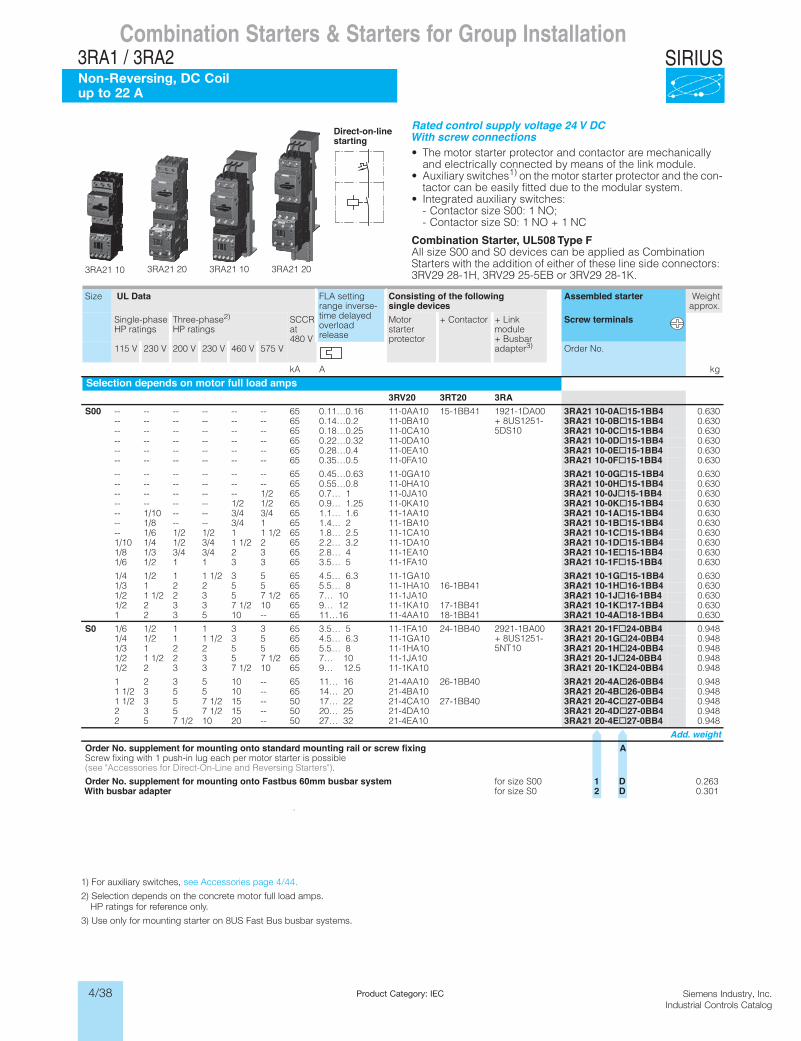
4/38 Siemens Industry, Inc.Industrial Controls Catalog
SIRIUS
Product Category: IEC
Siemens / Industrial Controls Previous folio: 4/4
Combination Starters & Starters for Group InstallationSIRIUS 3RA2 Motor Starters
3RA21 direct-on-line starters24 V DC
6/15SIRIUS Innovations Supplement 2012Illustrations are approximate
6
Rated control supply voltage 24 V DCWith screw connections• The motor starter protector and contactor are mechanically
and electrically connected by means of the link module.• Auxiliary switches1) on the motor starter protector and the con-
tactor can be easily fitted due to the modular system.• Integrated auxiliary switches:
- Contactor size S00: 1 NO; - Contactor size S0: 1 NO + 1 NC
Combination Starter, UL508 Type FAll size S00 and S0 devices can be applied as Combination Starters with the addition of either of these line side connectors: 3RV29 28-1H, 3RV29 25-5EB or 3RV29 28-1K.
.
3RA21 10 3RA21 20 3RA21 10 3RA21 20
Direct-on-linestarting
Size UL Data FLA setting range inverse-time delayed overload release
Consisting of the followingsingle devices
Assembled starter Weightapprox.
Single-phase HP ratings
Three-phase2) HP ratings
SCCR at 480 V
Motor starter protector
+ Contactor + Link module + Busbar adapter3)
Screw terminals
115 V 230 V 200 V 230 V 460 V 575 V Order No.
kA A kg
Selection depends on motor full load amps3RV20 3RT20 3RA
S00 -- -- -- -- -- -- 65 0.11…0.16 11-0AA10 15-1BB41 1921-1DA00 + 8US1251-5DS10
3RA21 10-0A@15-1BB4 0.630-- -- -- -- -- -- 65 0.14…0.2 11-0BA10 3RA21 10-0B@15-1BB4 0.630-- -- -- -- -- -- 65 0.18…0.25 11-0CA10 3RA21 10-0C@15-1BB4 0.630-- -- -- -- -- -- 65 0.22…0.32 11-0DA10 3RA21 10-0D@15-1BB4 0.630-- -- -- -- -- -- 65 0.28…0.4 11-0EA10 3RA21 10-0E@15-1BB4 0.630-- -- -- -- -- -- 65 0.35…0.5 11-0FA10 3RA21 10-0F@15-1BB4 0.630
-- -- -- -- -- -- 65 0.45…0.63 11-0GA10 3RA21 10-0G@15-1BB4 0.630-- -- -- -- -- -- 65 0.55…0.8 11-0HA10 3RA21 10-0H@15-1BB4 0.630-- -- -- -- -- 1/2 65 0.7… 1 11-0JA10 3RA21 10-0J@15-1BB4 0.630-- -- -- -- 1/2 1/2 65 0.9… 1.25 11-0KA10 3RA21 10-0K@15-1BB4 0.630-- 1/10 -- -- 3/4 3/4 65 1.1… 1.6 11-1AA10 3RA21 10-1A@15-1BB4 0.630-- 1/8 -- -- 3/4 1 65 1.4… 2 11-1BA10 3RA21 10-1B@15-1BB4 0.630-- 1/6 1/2 1/2 1 1 1/2 65 1.8… 2.5 11-1CA10 3RA21 10-1C@15-1BB4 0.6301/10 1/4 1/2 3/4 1 1/2 2 65 2.2… 3.2 11-1DA10 3RA21 10-1D@15-1BB4 0.6301/8 1/3 3/4 3/4 2 3 65 2.8… 4 11-1EA10 3RA21 10-1E@15-1BB4 0.6301/6 1/2 1 1 3 3 65 3.5… 5 11-1FA10 3RA21 10-1F@15-1BB4 0.630
1/4 1/2 1 1 1/2 3 5 65 4.5… 6.3 11-1GA10 3RA21 10-1G@15-1BB4 0.6301/3 1 2 2 5 5 65 5.5… 8 11-1HA10 16-1BB41 3RA21 10-1H@16-1BB4 0.6301/2 1 1/2 2 3 5 7 1/2 65 7… 10 11-1JA10 3RA21 10-1J@16-1BB4 0.6301/2 2 3 3 7 1/2 10 65 9… 12 11-1KA10 17-1BB41 3RA21 10-1K@17-1BB4 0.6301 2 3 5 10 -- 65 11…16 11-4AA10 18-1BB41 3RA21 10-4A@18-1BB4 0.630
S0 1/6 1/2 1 1 3 3 65 3.5… 5 11-1FA10 24-1BB40 2921-1BA00 + 8US1251-5NT10
3RA21 20-1F@24-0BB4 0.9481/4 1/2 1 1 1/2 3 5 65 4.5… 6.3 11-1GA10 3RA21 20-1G@24-0BB4 0.9481/3 1 2 2 5 5 65 5.5… 8 11-1HA10 3RA21 20-1H@24-0BB4 0.9481/2 1 1/2 2 3 5 7 1/2 65 7… 10 11-1JA10 3RA21 20-1J@24-0BB4 0.9481/2 2 3 3 7 1/2 10 65 9… 12.5 11-1KA10 3RA21 20-1K@24-0BB4 0.948
1 2 3 5 10 -- 65 11… 16 21-4AA10 26-1BB40 3RA21 20-4A@26-0BB4 0.9481 1/2 3 5 5 10 -- 65 14… 20 21-4BA10 3RA21 20-4B@26-0BB4 0.9481 1/2 3 5 7 1/2 15 -- 50 17… 22 21-4CA10 27-1BB40 3RA21 20-4C@27-0BB4 0.9482 3 5 7 1/2 15 -- 50 20… 25 21-4DA10 3RA21 20-4D@27-0BB4 0.9482 5 7 1/2 10 20 -- 50 27… 32 21-4EA10 3RA21 20-4E@27-0BB4 0.948
Add. weightAgnixifwercsroliargnitnuomdradnatsotnognitnuomroftnemelppus.oNredrO
Screw fixing with 1 push-in lug each per motor starter is possible (see "Accessories for Direct-On-Line and Reversing Starters").
Order No. supplement for mounting onto Fastbus 60mm busbar system for size S00 1 D 0.263With busbar adapter for size S0 2 D 0.301
LV1N_06_02.fm Page 15 Tuesday, September 24, 2013 10:52 AM
Combination Starters & Starters for Group Installation3RA1 / 3RA2Non-Reversing, DC Coilup to 22 A
1) For auxiliary switches, see Accessories page 4/44.
2) Selection depends on the concrete motor full load amps. HP ratings for reference only.
3) Use only for mounting starter on 8US Fast Bus busbar systems.
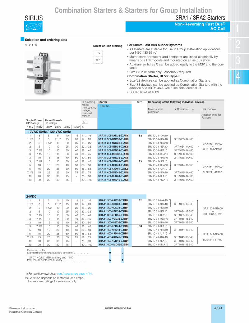
4/39Siemens Industry, Inc.Industrial Controls Catalog
SIRIUS
1) For auxiliary switches, see Accessories page 4/44.
2) Selection depends on motor full load amps. Horsepower ratings for reference only.
Product Category: IEC
Siemens / Industrial Controls Previous folio: 4/7
Combination Starters & Starters for Group Installation3RA1 / 3RA2 StartersNon-Reversing Fast Bus®
AC Coil
Selection and ordering data
Direct-on-line starting For 60mm Fast Bus busbar systemsAll starters are suitable for use in Group Installation applications per NEC 430-53 (c)Motor starter protector and contactor are linked electrically by means of a link module and mounted on a Fastbus shoe Auxiliary switches 1) can be added easily to the MSP and the con-tactor Size S3 is kit form only - assembly required
Combination Starter, UL508 Type F Size S2 devices can be applied as Combination Starters Size S3 devices can be applied as Combination Starters with the addition of a 3RT1946-4GA07 line side terminal kit
FLA setting rangeInverse-timedelayedoverloadrelease
Starter Size Consisting of the following individual devices
Order No.Motor starterprotector
+ Contactor + Link module+
Adapter shoe forFastbus
Single-PhaseHP Ratings
Three-Phase2)HP ratings
115V 230V 200V 230V 460V 575V A
110VAC 50Hz / 120 VAC 60Hz... 16
... 16
3RA11 3@-4AD33-@AK6 S2 3RV10 31-4AA10
3RA1931-1AA00+
8US1261-5FP08
3RA11 3@-4BD33-@AK6 3RV10 31-4BA10 3RT1033-1AK603RA11 3@-4DD33-@AK6 3RV10 31-4DA103RA11 3@-4ED34-@AK6 3RV10 31-4EA10 3RT1034-1AK603RA11 3@-4FD35-@AK6 3RV10 31-4FA10 3RT1035-1AK603RA11 3@-4GD36-@AK6 3RV10 31-4GA10 3RT1036-1AK603RA11 3@-4HD36-@AK6 3RV10 31-4HA10 3RT1036-1AK603RA11 4@-4FD44-@AK6 S3 3RV10 41-4FA10
3RA1941-1AA00+
8US1211-4TR00
3RA11 4@-4HD44-@AK6 3RV10 41-4HA10 3RT1044-1AK603RA11 4@-4JD44-@AK6 3RV10 41-4JA103RA11 4@-4KD45-@AK6 3RV10 41-4KA10 3RT1045-1AK603RA11 4@-4LD46-@AK6 3RV10 41-4LA10 3RT1046-1AK60
1 3 5 5 10 15 11 1 1/2 3 5 7 1/2 15 20 14 ... 20
2 5 7 1/2 10 20 25 18 ... 252 5 10 10 25 30 22 ... 323 7 1/2 10 15 30 40 28 ... 403 7 1/2 15 15 30 40 36 ... 453 10 15 15 40 50 40 ... 503 7 1/2 15 15 30 40 28 ... 405 10 15 20 40 50 36 ... 505 15 20 25 50 60 45 ... 63
7 1/2 15 25 25 60 75 57 ... 7510 20 30 30 75 – 70 ... 9010 20 30 30 75 – 80 ... 100
3RA11 4@-4MD46-@AK6 3RV10 41-4MA10 3RT1046-1AK60
1) For auxiliary switches, see accessories page 4/50.2) Selection depends on motor full load amps. Horse-
power ratings for reference only.
SCCR: 65kA at 480V
3RA11 30
24VDC 3RA11 3@-4AD33-@BB4 S2 3RV10 31-4AA10
3RA1931-1BA00+
8US1261-5FP08
3RA11 3@-4BD33-@BB4 3RV10 31-4BA10 3RT1033-1BB403RA11 3@-4DD33-@BB4 3RV10 31-4DA103RA11 3@-4ED34-@BB4 3RV10 31-4EA10 3RT1034-1BB403RA11 3@-4FD35-@BB4 3RV10 31-4FA10 3RT1035-1BB403RA11 3@-4GD36-@BB4 3RV10 31-4GA10 3RT1036-1BB403RA11 3@-4HD36-@BB4 3RV10 31-4HA10 3RT1036-1BB403RA11 4@-4FD44-@BB4 S3 3RV10 41-4FA10
3RA1941-1BA00+
8US1211-4TR00
3RA11 4@-4HD44-@BB4 3RV10 41-4HA10 3RT1044-1BB403RA11 4@-4JD44-@BB4 3RV10 41-4JA103RA11 4@-4KD45-@BB4 3RV10 41-4KA10 3RT1045-1BB403RA11 4@-4LD46-@BB4 3RV10 41-4LA10 3RT1046-1BB403RA11 4@-4MD46-@BB4 3RV10 41-4MA10 3RT1046-1BB40
Order No. suffixStandard unit without auxiliary contacts. . . . . . . . . . .
1 SPDT NO/NC MSP auxiliary and 1 NOfront mount contactor auxiliary. . . . . . . . . . . . . . . . . .
0
5
0
1
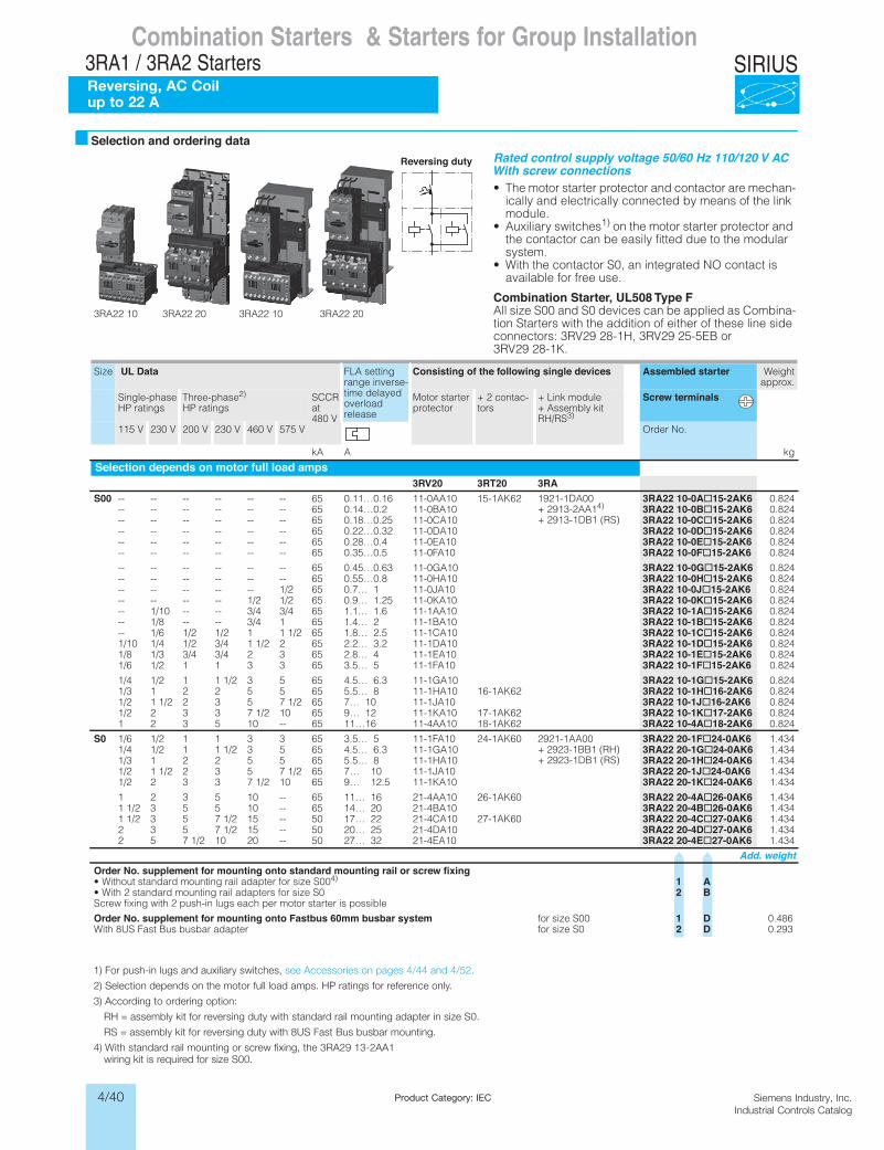
4/40 Siemens Industry, Inc.Industrial Controls Catalog
SIRIUS
Siemens / Industrial Controls Previous folio: LV1T 6/102
Product Category: IEC
Combination Starters & Starters for Group Installation3RA1 / 3RA2 StartersReversing, AC Coilup to 22 A
Combination Starters & Starters for Group InstallationSIRIUS 3RA2 Motor Starters
3RA22 reversing starters50/60 Hz 110/120 V AC
6/17SIRIUS Innovations Supplement 2012Illustrations are approximate
6
Selection and ordering data
3RA22 10 3RA22 20 3RA22 10 3RA22 20
Reversing duty Rated control supply voltage 50/60 Hz 110/120 V ACWith screw connections• The motor starter protector and contactor are mechan-
ically and electrically connected by means of the link module.
• Auxiliary switches1) on the motor starter protector and the contactor can be easily fitted due to the modular system.
• With the contactor S0, an integrated NO contact is available for free use.
Combination Starter, UL508 Type FAll size S00 and S0 devices can be applied as Combina-tion Starters with the addition of either of these line side connectors: 3RV29 28-1H, 3RV29 25-5EB or 3RV29 28-1K.
Size UL Data FLA setting range inverse-time delayed overload release
Consisting of the following single devices Assembled starter Weightapprox.
Single-phase HP ratings
Three-phase2) HP ratings
SCCR at 480 V
Motor starter protector
+ 2 contac-tors
+ Link module + Assembly kit RH/RS3)
Screw terminals
115 V 230 V 200 V 230 V 460 V 575 V Order No.
kA A kg
Selection depends on motor full load amps3RV20 3RT20 3RA
S00 -- -- -- -- -- -- 65 0.11…0.16 11-0AA10 15-1AK62 1921-1DA00 + 2913-2AA14)
+ 2913-1DB1 (RS)
3RA22 10-0A@15-2AK6 0.824-- -- -- -- -- -- 65 0.14…0.2 11-0BA10 3RA22 10-0B@15-2AK6 0.824-- -- -- -- -- -- 65 0.18…0.25 11-0CA10 3RA22 10-0C@15-2AK6 0.824-- -- -- -- -- -- 65 0.22…0.32 11-0DA10 3RA22 10-0D@15-2AK6 0.824-- -- -- -- -- -- 65 0.28…0.4 11-0EA10 3RA22 10-0E@15-2AK6 0.824-- -- -- -- -- -- 65 0.35…0.5 11-0FA10 3RA22 10-0F@15-2AK6 0.824
-- -- -- -- -- -- 65 0.45…0.63 11-0GA10 3RA22 10-0G@15-2AK6 0.824-- -- -- -- -- -- 65 0.55…0.8 11-0HA10 3RA22 10-0H@15-2AK6 0.824-- -- -- -- -- 1/2 65 0.7… 1 11-0JA10 3RA22 10-0J@15-2AK6 0.824-- -- -- -- 1/2 1/2 65 0.9… 1.25 11-0KA10 3RA22 10-0K@15-2AK6 0.824-- 1/10 -- -- 3/4 3/4 65 1.1… 1.6 11-1AA10 3RA22 10-1A@15-2AK6 0.824-- 1/8 -- -- 3/4 1 65 1.4… 2 11-1BA10 3RA22 10-1B@15-2AK6 0.824-- 1/6 1/2 1/2 1 1 1/2 65 1.8… 2.5 11-1CA10 3RA22 10-1C@15-2AK6 0.8241/10 1/4 1/2 3/4 1 1/2 2 65 2.2… 3.2 11-1DA10 3RA22 10-1D@15-2AK6 0.8241/8 1/3 3/4 3/4 2 3 65 2.8… 4 11-1EA10 3RA22 10-1E@15-2AK6 0.8241/6 1/2 1 1 3 3 65 3.5… 5 11-1FA10 3RA22 10-1F@15-2AK6 0.824
1/4 1/2 1 1 1/2 3 5 65 4.5… 6.3 11-1GA10 3RA22 10-1G@15-2AK6 0.8241/3 1 2 2 5 5 65 5.5… 8 11-1HA10 16-1AK62 3RA22 10-1H@16-2AK6 0.8241/2 1 1/2 2 3 5 7 1/2 65 7… 10 11-1JA10 3RA22 10-1J@16-2AK6 0.8241/2 2 3 3 7 1/2 10 65 9… 12 11-1KA10 17-1AK62 3RA22 10-1K@17-2AK6 0.8241 2 3 5 10 -- 65 11…16 11-4AA10 18-1AK62 3RA22 10-4A@18-2AK6 0.824
S0 1/6 1/2 1 1 3 3 65 3.5… 5 11-1FA10 24-1AK60 2921-1AA00 + 2923-1BB1 (RH) + 2923-1DB1 (RS)
3RA22 20-1F@24-0AK6 1.4341/4 1/2 1 1 1/2 3 5 65 4.5… 6.3 11-1GA10 3RA22 20-1G@24-0AK6 1.4341/3 1 2 2 5 5 65 5.5… 8 11-1HA10 3RA22 20-1H@24-0AK6 1.4341/2 1 1/2 2 3 5 7 1/2 65 7… 10 11-1JA10 3RA22 20-1J@24-0AK6 1.4341/2 2 3 3 7 1/2 10 65 9… 12.5 11-1KA10 3RA22 20-1K@24-0AK6 1.434
1 2 3 5 10 -- 65 11… 16 21-4AA10 26-1AK60 3RA22 20-4A@26-0AK6 1.4341 1/2 3 5 5 10 -- 65 14… 20 21-4BA10 3RA22 20-4B@26-0AK6 1.4341 1/2 3 5 7 1/2 15 -- 50 17… 22 21-4CA10 27-1AK60 3RA22 20-4C@27-0AK6 1.4342 3 5 7 1/2 15 -- 50 20… 25 21-4DA10 3RA22 20-4D@27-0AK6 1.4342 5 7 1/2 10 20 -- 50 27… 32 21-4EA10 3RA22 20-4E@27-0AK6 1.434
Add. weightOrder No. supplement for mounting onto standard mounting rail or screw fixing• Without standard mounting rail adapter for size S004) 1 A• With 2 standard mounting rail adapters for size S0 2 BScrew fixing with 2 push-in lugs each per motor starter is possible
Order No. supplement for mounting onto Fastbus 60mm busbar system for size S00 1 D 0.4860S ezis rofretpada rabsub suB tsaF SU8 htiW 2 D 0.293
LV1N_06_02.fm Page 17 Tuesday, September 24, 2013 10:52 AM
1) For push-in lugs and auxiliary switches, see Accessories on pages 4/44 and 4/52.
2) Selection depends on the motor full load amps. HP ratings for reference only.
3) According to ordering option:
RH = assembly kit for reversing duty with standard rail mounting adapter in size S0.
RS = assembly kit for reversing duty with 8US Fast Bus busbar mounting.
4) With standard rail mounting or screw fixing, the 3RA29 13-2AA1 wiring kit is required for size S00.
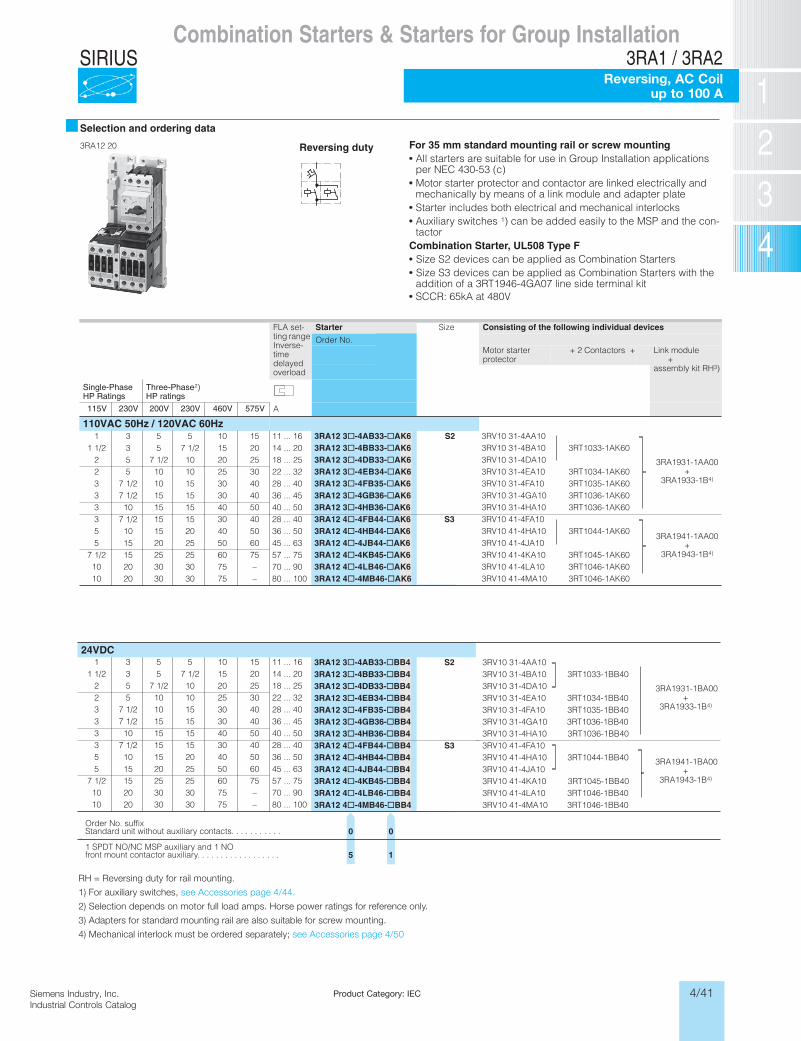
4/41Siemens Industry, Inc.Industrial Controls Catalog
SIRIUS
Siemens / Industrial Controls Previous folio: LV1T 6/105
RH = Reversing duty for rail mounting.
1) For auxiliary switches, see Accessories page 4/44.
2) Selection depends on motor full load amps. Horse power ratings for reference only.
3) Adapters for standard mounting rail are also suitable for screw mounting.
4) Mechanical interlock must be ordered separately; see Accessories page 4/50
Product Category: IEC
Siemens / Industrial Controls Previous folio: 4/11
Combination Starters & Starters for Group Installation3RA1 / 3RA2
Reversing, AC Coilup to 100 A
Selection and ordering data
Reversing duty For 35 mm standard mounting rail or screw mountingAll starters are suitable for use in Group Installation applications per NEC 430-53 (c)Motor starter protector and contactor are linked electrically and mechanically by means of a link module and adapter plateStarter includes both electrical and mechanical interlocksAuxiliary switches 1) can be added easily to the MSP and the con-tactor
Combination Starter, UL508 Type F Size S2 devices can be applied as Combination Starters Size S3 devices can be applied as Combination Starters with the addition of a 3RT1946-4GA07 line side terminal kit
FLA set-ting range Inverse-timedelayedoverload
Starter Size Consisting of the following individual devices
Order No.Motor starterprotector
+ 2 Contactors + Link module+
assembly kit RH3)
Single-PhaseHP Ratings
Three-Phase2)HP ratings
115V 230V 200V 230V 460V 575V A
110VAC 50Hz / 120VAC 60Hz1 3 5 5 10 15 11 ... 16 3RA12 3@-4AB33-@AK6 S2 3RV10 31-4AA10
3RA1931-1AA00+
3RA1933-1B4)
1 1/2 3 5 7 1/2 15 20 14 ... 20 3RA12 3@-4BB33-@AK6 3RV10 31-4BA10 3RT1033-1AK602 5 7 1/2 10 20 25 18 ... 25 3RA12 3@-4DB33-@AK6 3RV10 31-4DA102 5 10 10 25 30 22 ... 32 3RA12 3@-4EB34-@AK6 3RV10 31-4EA10 3RT1034-1AK603 7 1/2 10 15 30 40 28 ... 40 3RA12 3@-4FB35-@AK6 3RV10 31-4FA10 3RT1035-1AK603 7 1/2 15 15 30 40 36 ... 45 3RA12 3@-4GB36-@AK6 3RV10 31-4GA10 3RT1036-1AK603 10 15 15 40 50 40 ... 50 3RA12 3@-4HB36-@AK6 3RV10 31-4HA10 3RT1036-1AK603 7 1/2 15 15 30 40 28 ... 40 3RA12 4@-4FB44-@AK6 S3 3RV10 41-4FA10
3RA1941-1AA00+
3RA1943-1B4)
5 10 15 20 40 50 36 ... 50 3RA12 4@-4HB44-@AK6 3RV10 41-4HA10 3RT1044-1AK605 15 20 25 50 60 45 ... 63 3RA12 4@-4JB44-@AK6 3RV10 41-4JA10
7 1/2 15 25 25 60 75 57 ... 75 3RA12 4@-4KB45-@AK6 3RV10 41-4KA10 3RT1045-1AK6010 20 30 30 75 – 70 ... 90 3RA12 4@-4LB46-@AK6 3RV10 41-4LA10 3RT1046-1AK6010 20 30 30 75 – 80 ... 100 3RA12 4@-4MB46-@AK6 3RV10 41-4MA10 3RT1046-1AK60
RH = Reversing duty for rail mounting.1) For auxiliary switches, see accessories page 4/44.2) Selection depends on motor full load amps. Horse
power ratings for reference only.
3) Adapters for standard mounting rail are also suitable for screw mounting.
4) Mechanical interlock must be ordered separately; see accessories page 4/50.
1 3 5 5 10 15 11 ... 161 1/2 3 5 7 1/2 15 20 14 ... 20
2 5 7 1/2 10 20 25 18 ... 252 5 10 10 25 30 22 ... 323 7 1/2 10 15 30 40 28 ... 403 7 1/2 15 15 30 40 36 ... 453 10 15 15 40 50 40 ... 503 7 1/2 15 15 30 40 28 ... 405 10 15 20 40 50 36 ... 505 15 20 25 50 60 45 ... 63
7 1/2 15 25 25 60 75 57 ... 7510 20 30 30 75 – 70 ... 9010 20 30 30 75 – 80 ... 100
3RA12 20
SCCR: 65kA at 480V
24VDC3RA12 3@-4AB33-@BB4 S2 3RV10 31-4AA10
3RA1931-1BA00+
3RA1933-1B4)
3RA12 3@-4BB33-@BB4 3RV10 31-4BA10 3RT1033-1BB403RA12 3@-4DB33-@BB4 3RV10 31-4DA103RA12 3@-4EB34-@BB4 3RV10 31-4EA10 3RT1034-1BB403RA12 3@-4FB35-@BB4 3RV10 31-4FA10 3RT1035-1BB403RA12 3@-4GB36-@BB4 3RV10 31-4GA10 3RT1036-1BB403RA12 3@-4HB36-@BB4 3RV10 31-4HA10 3RT1036-1BB403RA12 4@-4FB44-@BB4 S3 3RV10 41-4FA10
3RA1941-1BA00+
3RA1943-1B4)
3RA12 4@-4HB44-@BB4 3RV10 41-4HA10 3RT1044-1BB403RA12 4@-4JB44-@BB4 3RV10 41-4JA103RA12 4@-4KB45-@BB4 3RV10 41-4KA10 3RT1045-1BB403RA12 4@-4LB46-@BB4 3RV10 41-4LA10 3RT1046-1BB403RA12 4@-4MB46-@BB4 3RV10 41-4MA10 3RT1046-1BB40
Order No. suffixStandard unit without auxiliary contacts. . . . . . . . . . .
1 SPDT NO/NC MSP auxiliary and 1 NOfront mount contactor auxiliary. . . . . . . . . . . . . . . . . .
0
5
0
1
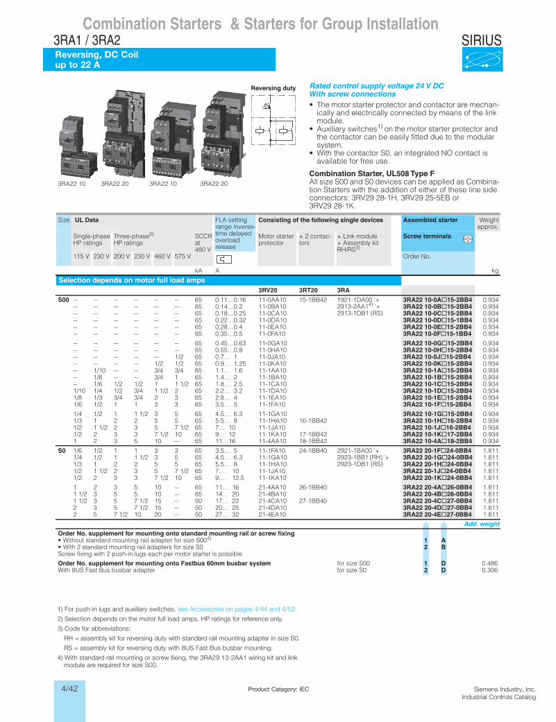
4/42 Siemens Industry, Inc.Industrial Controls Catalog
SIRIUS
Siemens / Industrial Controls Previous folio: 4/12
Product Category: IEC
Combination Starters & Starters for Group Installation3RA1 / 3RA2Reversing, DC Coil up to 22 A
Combination Starters & Starters for Group InstallationSIRIUS 3RA2 Motor Starters
3RA22 reversing starters24 V DC
6/19SIRIUS Innovations Supplement 2012Illustrations are approximate
6
3RA22 10 3RA22 20 3RA22 10 3RA22 20
Reversing duty Rated control supply voltage 24 V DCWith screw connections• The motor starter protector and contactor are mechan-
ically and electrically connected by means of the link module.
• Auxiliary switches1) on the motor starter protector and the contactor can be easily fitted due to the modular system.
• With the contactor S0, an integrated NO contact is available for free use.
Combination Starter, UL508 Type FAll size S00 and S0 devices can be applied as Combina-tion Starters with the addition of either of these line side connectors: 3RV29 28-1H, 3RV29 25-5EB or 3RV29 28-1K.
Size UL Data FLA setting range inverse-time delayed overload release
Consisting of the following single devices Assembled starter Weightapprox.
Single-phase HP ratings
Three-phase2) HP ratings
SCCR at 480 V
Motor starter protector
+ 2 contac-tors
+ Link module + Assembly kit RH/RS3)
Screw terminals
115 V 230 V 200 V 230 V 460 V 575 V Order No.
kA A kg
Selection depends on motor full load amps3RV20 3RT20 3RA
S00 -- -- -- -- -- -- 65 0.11…0.16 11-0AA10 15-1BB42 1921-1DA00 '+ 2913-2AA14) '+ 2913-1DB1 (RS)
3RA22 10-0A@15-2BB4 0.934-- -- -- -- -- -- 65 0.14…0.2 11-0BA10 3RA22 10-0B@15-2BB4 0.934-- -- -- -- -- -- 65 0.18…0.25 11-0CA10 3RA22 10-0C@15-2BB4 0.934-- -- -- -- -- -- 65 0.22…0.32 11-0DA10 3RA22 10-0D@15-1BB4 0.934-- -- -- -- -- -- 65 0.28…0.4 11-0EA10 3RA22 10-0E@15-2BB4 0.934-- -- -- -- -- -- 65 0.35…0.5 11-0FA10 3RA22 10-0F@15-1BB4 0.934
-- -- -- -- -- -- 65 0.45…0.63 11-0GA10 3RA22 10-0G@15-2BB4 0.934-- -- -- -- -- -- 65 0.55…0.8 11-0HA10 3RA22 10-0H@15-2BB4 0.934-- -- -- -- -- 1/2 65 0.7… 1 11-0JA10 3RA22 10-0J@15-2BB4 0.934-- -- -- -- 1/2 1/2 65 0.9… 1.25 11-0KA10 3RA22 10-0K@15-2BB4 0.934-- 1/10 -- -- 3/4 3/4 65 1.1… 1.6 11-1AA10 3RA22 10-1A@15-2BB4 0.934-- 1/8 -- -- 3/4 1 65 1.4… 2 11-1BA10 3RA22 10-1B@15-2BB4 0.934-- 1/6 1/2 1/2 1 1 1/2 65 1.8… 2.5 11-1CA10 3RA22 10-1C@15-2BB4 0.9341/10 1/4 1/2 3/4 1 1/2 2 65 2.2… 3.2 11-1DA10 3RA22 10-1D@15-2BB4 0.9341/8 1/3 3/4 3/4 2 3 65 2.8… 4 11-1EA10 3RA22 10-1E@15-2BB4 0.9341/6 1/2 1 1 3 3 65 3.5… 5 11-1FA10 3RA22 10-1F@15-2BB4 0.934
1/4 1/2 1 1 1/2 3 5 65 4.5… 6.3 11-1GA10 3RA22 10-1G@15-2BB4 0.9341/3 1 2 2 5 5 65 5.5… 8 11-1HA10 16-1BB42 3RA22 10-1H@16-2BB4 0.9341/2 1 1/2 2 3 5 7 1/2 65 7… 10 11-1JA10 3RA22 10-1J@16-2BB4 0.9341/2 2 3 3 7 1/2 10 65 9… 12 11-1KA10 17-1BB42 3RA22 10-1K@17-2BB4 0.9341 2 3 5 10 -- 65 11…16 11-4AA10 18-1BB42 3RA22 10-4A@18-2BB4 0.934
S0 1/6 1/2 1 1 3 3 65 3.5… 5 11-1FA10 24-1BB40 2921-1BA00 '+ 2923-1BB1 (RH) '+ 2923-1DB1 (RS)
3RA22 20-1F@24-0BB4 1.8111/4 1/2 1 1 1/2 3 5 65 4.5… 6.3 11-1GA10 3RA22 20-1G@24-0BB4 1.8111/3 1 2 2 5 5 65 5.5… 8 11-1HA10 3RA22 20-1H@24-0BB4 1.8111/2 1 1/2 2 3 5 7 1/2 65 7… 10 11-1JA10 3RA22 20-1J@24-0BB4 1.8111/2 2 3 3 7 1/2 10 65 9… 12.5 11-1KA10 3RA22 20-1K@24-0BB4 1.811
1 2 3 5 10 -- 65 11… 16 21-4AA10 26-1BB40 3RA22 20-4A@26-0BB4 1.8111 1/2 3 5 5 10 -- 65 14… 20 21-4BA10 3RA22 20-4B@26-0BB4 1.8111 1/2 3 5 7 1/2 15 -- 50 17… 22 21-4CA10 27-1BB40 3RA22 20-4C@27-0BB4 1.8112 3 5 7 1/2 15 -- 50 20… 25 21-4DA10 3RA22 20-4D@27-0BB4 1.8112 5 7 1/2 10 20 -- 50 27… 32 21-4EA10 3RA22 20-4E@27-0BB4 1.811
Add. weightOrder No. supplement for mounting onto standard mounting rail or screw fixing• Without standard mounting rail adapter for size S004) 1 A• With 2 standard mounting rail adapters for size S0 2 BScrew fixing with 2 push-in lugs each per motor starter is possible
Order No. supplement for mounting onto Fastbus 60mm busbar system for size S00 1 D 0.4860S ezis rofretpada rabsub suB tsaF SU8 htiW 2 D 0.306
LV1N_06_02.fm Page 19 Tuesday, September 24, 2013 10:52 AM
1) For push-in lugs and auxiliary switches, see Accessories on pages 4/44 and 4/52.
2) Selection depends on the motor full load amps. HP ratings for reference only.
3) Code for abbreviations:
RH = assembly kit for reversing duty with standard rail mounting adapter in size S0.
RS = assembly kit for reversing duty with 8US Fast Bus busbar mounting.
4) With standard rail mounting or screw fixing, the 3RA29 13-2AA1 wiring kit and link module are required for size S00.
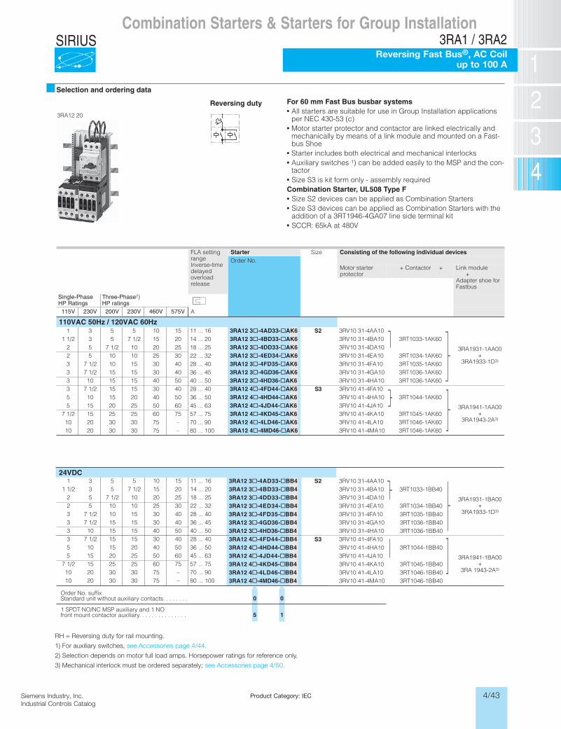
4/43Siemens Industry, Inc.Industrial Controls Catalog
SIRIUS
Product Category: IEC
Siemens / Industrial Controls Previous folio: 4/15
Combination Starters & Starters for Group Installation3RA1 / 3RA2
Reversing Fast Bus®, AC Coilup to 100 A
Selection and ordering data
Reversing duty For 60 mm Fast Bus busbar systemsAll starters are suitable for use in Group Installation applications per NEC 430-53 (c)Motor starter protector and contactor are linked electrically and mechanically by means of a link module and mounted on a Fast-bus ShoeStarter includes both electrical and mechanical interlocksAuxiliary switches 1) can be added easily to the MSP and the con-tactor Size S3 is kit form only - assembly required
Combination Starter, UL508 Type F Size S2 devices can be applied as Combination Starters Size S3 devices can be applied as Combination Starters with the addition of a 3RT1946-4GA07 line side terminal kit
FLA setting rangeInverse-timedelayed overloadrelease
Starter Size Consisting of the following individual devicesOrder No.
Motor starterprotector
+ Contactor + Link module+
Adapter shoe forFastbus
Single-PhaseHP Ratings
Three-Phase2)HP ratings
115V 230V 200V 230V 460V 575V A
1 3 5 5 10 15 11 ... 16 3RA12 3@-4AD33-@AK6 S2 3RV10 31-4AA10
3RA1931-1AA00+
3RA1933-1D3)
1 1/2 3 5 7 1/2 15 20 14 ... 20 3RA12 3@-4BD33-@AK6 3RV10 31-4BA10 3RT1033-1AK602 5 7 1/2 10 20 25 18 ... 25 3RA12 3@-4DD33-@AK6 3RV10 31-4DA102 5 10 10 25 30 22 ... 32 3RA12 3@-4ED34-@AK6 3RV10 31-4EA10 3RT1034-1AK603 7 1/2 10 15 30 40 28 ... 40 3RA12 3@-4FD35-@AK6 3RV10 31-4FA10 3RT1035-1AK603 7 1/2 15 15 30 40 36 ... 45 3RA12 3@-4GD36-@AK6 3RV10 31-4GA10 3RT1036-1AK603 10 15 15 40 50 40 ... 50 3RA12 3@-4HD36-@AK6 3RV10 31-4HA10 3RT1036-1AK603 7 1/2 15 15 30 40 28 ... 40 3RA12 4@-4FD44-@AK6 S3 3RV10 41-4FA10
3RA1941-1AA00+
3RA1943-2A3)
5 10 15 20 40 50 36 ... 50 3RA12 4@-4HD44-@AK6 3RV10 41-4HA10 3RT1044-1AK605 15 20 25 50 60 45 ... 63 3RA12 4@-4JD44-@AK6 3RV10 41-4JA10
7 1/2 15 25 25 60 75 57 ... 75 3RA12 4@-4KD45-@AK6 3RV10 41-4KA10 3RT1045-1AK6010 20 30 30 75 – 70 ... 90 3RA12 4@-4LD46-@AK6 3RV10 41-4LA10 3RT1046-1AK6010 20 30 30 75 – 80 ... 100 3RA12 4@-4MD46-@AK6 3RV10 41-4MA10 3RT1046-1AK60
RH = Reversing duty for rail mounting.1) For auxiliary switches, see accessories page 4/44.2) Selection depends on motor full load amps. Horse-
power ratings for reference only.
3) Mechanical interlock must be ordered separately; see accessories page 4/50.
3RA12 20
SCCR: 65kA at 480V
110VAC 50Hz / 120VAC 60Hz
24VDC3RA12 3@-4AD33-@BB4 S2 3RV10 31-4AA10
3RA1931-1BA00+
3RA1933-1D3)
3RA12 3@-4BD33-@BB4 3RV10 31-4BA10 3RT1033-1BB403RA12 3@-4DD33-@BB4 3RV10 31-4DA103RA12 3@-4ED34-@BB4 3RV10 31-4EA10 3RT1034-1BB403RA12 3@-4FD35-@BB4 3RV10 31-4FA10 3RT1035-1BB403RA12 3@-4GD36-@BB4 3RV10 31-4GA10 3RT1036-1BB403RA12 3@-4HD36-@BB4 3RV10 31-4HA10 3RT1036-1BB403RA12 4@-4FD44-@BB4 S3 3RV10 41-4FA10
3RA1941-1BA00+
3RA 1943-2A3)
3RA12 4@-4HD44-@BB4 3RV10 41-4HA10 3RT1044-1BB403RA12 4@-4JD44-@BB4 3RV10 41-4JA103RA12 4@-4KD45-@BB4 3RV10 41-4KA10 3RT1045-1BB403RA12 4@-4LD46-@BB4 3RV10 41-4LA10 3RT1046-1BB403RA12 4@-4MD46-@BB4 3RV10 41-4MA10 3RT1046-1BB40
Order No. suffixStandard unit without auxiliary contacts. . . . . . . .
1 SPDT NO/NC MSP auxiliary and 1 NOfront mount contactor auxiliary. . . . . . . . . . . . . . .
0
5
0
1
1 3 5 5 10 15 11 ... 161 1/2 3 5 7 1/2 15 20 14 ... 20
2 5 7 1/2 10 20 25 18 ... 252 5 10 10 25 30 22 ... 323 7 1/2 10 15 30 40 28 ... 403 7 1/2 15 15 30 40 36 ... 453 10 15 15 40 50 40 ... 503 7 1/2 15 15 30 40 28 ... 405 10 15 20 40 50 36 ... 505 15 20 25 50 60 45 ... 63
7 1/2 15 25 25 60 75 57 ... 7510 20 30 30 75 – 70 ... 9010 20 30 30 75 – 80 ... 100
RH = Reversing duty for rail mounting.
1) For auxiliary switches, see Accessories page 4/44.
2) Selection depends on motor full load amps. Horsepower ratings for reference only.
3) Mechanical interlock must be ordered separately; see Accessories page 4/50.
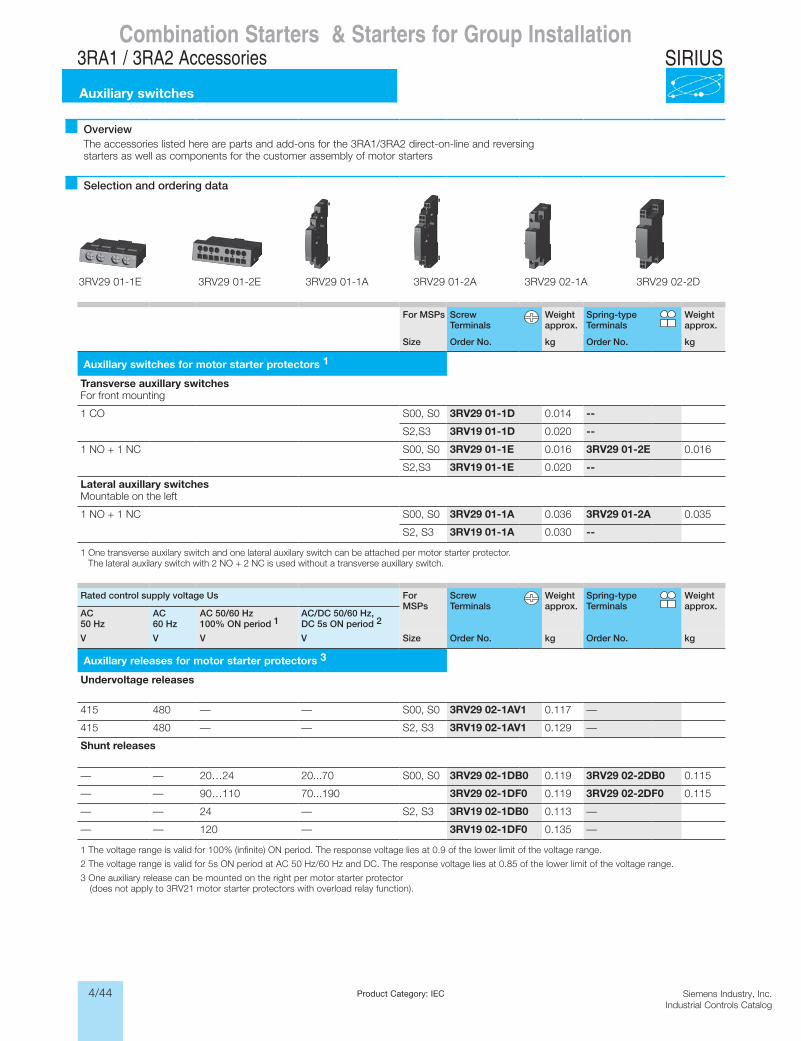
4/44 Siemens Industry, Inc.Industrial Controls Catalog
SIRIUS
Product Category: IEC
Siemens / Industrial Controls Previous folio: 4/18
OverviewThe accessories listed here are parts and add-ons for the 3RA1/3RA2 direct-on-line and reversing starters as well as components for the customer assembly of motor starters
Selection and ordering data
For MSPs Screw Terminals
Weight approx.
Spring-type Terminals
Weight approx.
Size Order No. kg Order No. kg
Auxillary switches for motor starter protectors 1
Transverse auxillary switches For front mounting
1 CO S00, S0 3RV29 01-1D 0.014 --
S2,S3 3RV19 01-1D 0.020 --
1 NO + 1 NC S00, S0 3RV29 01-1E 0.016 3RV29 01-2E 0.016
S2,S3 3RV19 01-1E 0.020 --
Lateral auxillary switches Mountable on the left
1 NO + 1 NC S00, S0 3RV29 01-1A 0.036 3RV29 01-2A 0.035
S2, S3 3RV19 01-1A 0.030 --
1 One transverse auxilary switch and one lateral auxilary switch can be attached per motor starter protector. The lateral auxilary switch with 2 NO + 2 NC is used without a transverse auxillary switch.
Rated control supply voltage Us For MSPs
Screw Terminals
Weight approx.
Spring-type Terminals
Weight approx.
AC 50 Hz
AC 60 Hz
AC 50/60 Hz100% ON period 1
AC/DC 50/60 Hz, DC 5s ON period 2
V V V V Size Order No. kg Order No. kg
Auxillary releases for motor starter protectors 3
Undervoltage releases
415 480 — — S00, S0 3RV29 02-1AV1 0.117 —
415 480 — — S2, S3 3RV19 02-1AV1 0.129 —
Shunt releases
— — 20…24 20...70 S00, S0 3RV29 02-1DB0 0.119 3RV29 02-2DB0 0.115
— — 90…110 70...190 3RV29 02-1DF0 0.119 3RV29 02-2DF0 0.115
— — 24 — S2, S3 3RV19 02-1DB0 0.113 —
— — 120 — 3RV19 02-1DF0 0.135 —
1 The voltage range is valid for 100% (infinite) ON period. The response voltage lies at 0.9 of the lower limit of the voltage range.
2 The voltage range is valid for 5s ON period at AC 50 Hz/60 Hz and DC. The response voltage lies at 0.85 of the lower limit of the voltage range.
3 One auxiliary release can be mounted on the right per motor starter protector (does not apply to 3RV21 motor starter protectors with overload relay function).
3RV29 01-1E 3RV29 01-2E 3RV29 01-1A 3RV29 01-2A 3RV29 02-1A 3RV29 02-2D
Combination Starters & Starters for Group Installation3RA1 / 3RA2 Accessories
Auxiliary switches
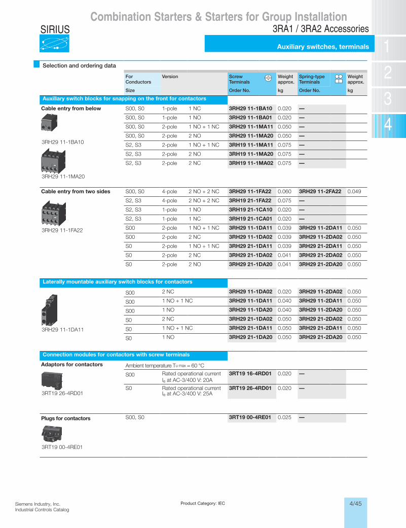
4/45Siemens Industry, Inc.Industrial Controls Catalog
SIRIUS
Product Category: IEC
Siemens / Industrial Controls Previous folio: 4/19
Selection and ordering data
For Conductors
Version Screw Terminals
Weight approx.
Spring-type Terminals
Weight approx.
Size Order No. kg Order No. kg
Auxillary switch blocks for snapping on the front for contactors
Cable entry from below S00, S0 1-pole 1 NC 3RH29 11-1BA10 0.020 —
S00, S0 1-pole 1 NO 3RH29 11-1BA01 0.020 —
S00, S0 2-pole 1 NO + 1 NC 3RH29 11-1MA11 0.050 —
S00, S0 2-pole 2 NO 3RH29 11-1MA20 0.050 —
S2, S3 2-pole 1 NO + 1 NC 3RH19 11-1MA11 0.075 —
S2, S3 2-pole 2 NO 3RH19 11-1MA20 0.075 —
S2, S3 2-pole 2 NC 3RH19 11-1MA02 0.075 —
Cable entry from two sides S00, S0 4-pole 2 NO + 2 NC 3RH29 11-1FA22 0.060 3RH29 11-2FA22 0.049
S2, S3 4-pole 2 NO + 2 NC 3RH19 21-1FA22 0.075 —
S2, S3 1-pole 1 NO 3RH19 21-1CA10 0.020 —
S2, S3 1-pole 1 NC 3RH19 21-1CA01 0.020 —
S00 2-pole 1 NO + 1 NC 3RH29 11-1DA11 0.039 3RH29 11-2DA11 0.050
S00 2-pole 2 NC 3RH29 11-1DA02 0.039 3RH29 11-2DA02 0.050
S0 2-pole 1 NO + 1 NC 3RH29 21-1DA11 0.039 3RH29 21-2DA11 0.050
S0 2-pole 2 NC 3RH29 21-1DA02 0.041 3RH29 21-2DA02 0.050
S0 2-pole 2 NO 3RH29 21-1DA20 0.041 3RH29 21-2DA20 0.050
Laterally mountable auxiliary switch blocks for contactors
S00 2 NC 3RH29 11-1DA02 0.020 3RH29 11-2DA02 0.050
S00 1 NO + 1 NC 3RH29 11-1DA11 0.040 3RH29 11-2DA11 0.050
S00 1 NO 3RH29 11-1DA20 0.040 3RH29 11-2DA20 0.050
S0 2 NC 3RH29 21-1DA02 0.050 3RH29 21-2DA02 0.050
S0 1 NO + 1 NC 3RH29 21-1DA11 0.050 3RH29 21-2DA11 0.050
S0 1 NO 3RH29 21-1DA20 0.050 3RH29 21-2DA20 0.050
Connection modules for contactors with screw terminals
Adaptors for contactors Ambient temperature Tu max = 60 °C
S00 Rated operational current Ie at AC-3/400 V: 20A
3RT19 16-4RD01 0.020 —
S0 Rated operational current Ie at AC-3/400 V: 25A
3RT19 26-4RD01 0.020 —
Plugs for contactors S00, S0 3RT19 00-4RE01 0.025 —
3RH29 11-1MA20
3RH29 11-1FA22
3RH29 11-1DA11
3RT19 26-4RD01
3RT19 00-4RE01
3RH29 11-1BA10
Combination Starters & Starters for Group Installation3RA1 / 3RA2 Accessories
Auxiliary switches, terminals
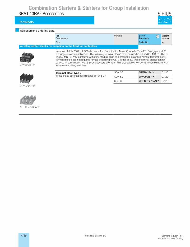
4/46 Siemens Industry, Inc.Industrial Controls Catalog
SIRIUS
Product Category: IEC
Siemens / Industrial Controls Previous folio: 4/20
Combination Starters & Starters for Group Installation3RA1 / 3RA2 Accessories
Terminals
Selection and ordering data
For Conductors
Version Screw Terminals
Weight approx.
Size Order No. kg
Auxillary switch blocks for snapping on the front for contactors
Note: As of July 2001, UL 508 demands for “Combination Motor Controller Type E” 1” air gaps and 2” creepage distances at lineside. The following terminal blocks must be used in S0 and S3 MSP’s 3RV10. The S2 MSP 3RV10 conforms with stipulated air gaps and creepage distances without terminal block.Terminal blocks are not required for use according to CSA. With size S0 these terminal blocks cannot be used in combination with 3-phase busbars 3RV19.5. This also applies to size S3 in combination with transverse auxiliary switches.
Terminal block type Efor extended air/creepage distance (1” and 2”)
S00, S0 3RV29 28-1H 0.120
S00, S0 3RV29 28-1K 0.120
S2, S3 3RT19 46-4GA07 0.120
3RV29 28-1K
3RT19 46-4GA07
3RV29 28-1H
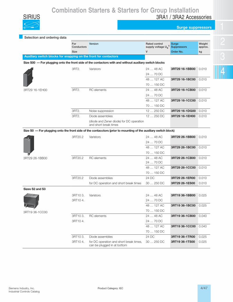
4/47Siemens Industry, Inc.Industrial Controls Catalog
SIRIUS
Product Category: IEC
Siemens / Industrial Controls Previous folio: 4/21
Combination Starters & Starters for Group Installation3RA1 / 3RA2 Accessories
Surge suppressors
Selection and ordering data
For Conductors
Version Rated control supply voltage Us
1Surge Suppressors
Weight approx.
Size V Order No. kg
Auxillary switch blocks for snapping on the front for contactors
Size S00 — For plugging onto the front side of the contactors with and without auxiliary switch blocks
3RT2. Varistors 24 … 48 AC 3RT29 16-1BB00 0.010
24 … 70 DC
48 … 127 AC 3RT29 16-1BC00 0.010
70 … 150 DC
3RT2. RC elements 24 … 48 AC 3RT29 16-1CB00 0.010
24 … 70 DC
48 … 127 AC 3RT29 16-1CC00 0.010
70 … 150 DC
3RT2. Noise suppression 12 … 250 DC 3RT29 16-1DG00 0.010
3RT2. Diode assemblies 12 … 250 DC 3RT29 16-1EH00 0.010
(diode and Zener diode) for DC operation and short break times
Size S0 — For plugging onto the front side of the contacctors (prior to mounting of the auxiliary switch block)
3RT20.2 Varistors 24 … 48 AC 3RT29 26-1BB00 0.010
24 … 70 DC
48 … 127 AC 3RT29 26-1BC00 0.010
70 … 150 DC
3RT20.2 RC elements 24 … 48 AC 3RT29 26-1CB00 0.01024 … 70 DC
48 … 127 AC 3RT29 26-1CC00 0.010
70 … 150 DC
3RT20.2 Diode assemblies 24 DC 3RT29 26-1ER00 0.010
for DC operation and short break times 30 … 250 DC 3RT29 26-1ES00 0.010
Sizes S2 and S3
3RT10 3. Varistors 24 … 48 AC 3RT19 36-1BB00 0.025
3RT10 4. 24 … 70 DC
48 … 127 AC 3RT19 36-1BC00 0.025
70 … 150 DC
3RT10 3. RC elements 24 … 48 AC 3RT19 36-1CB00 0.040
3RT10 4. 24 … 70 DC
48 … 127 AC 3RT19 36-1CC00 0.040
70 … 150 DC
3RT10 3. Diode assemblies 24 DC 3RT19 36-1TR00 0.025
3RT10 4. for DC operation and short break times, can be plugged in at bottom
30 … 250 DC 3RT19 36-1TS00 0.025
3RT29 16-1EH00
3RT29 26-1BB00
3RT19 36-1CC00
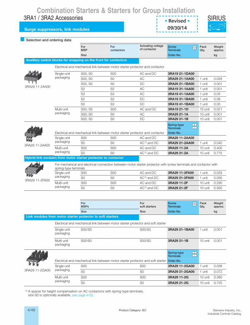
4/48 Siemens Industry, Inc.Industrial Controls Catalog
SIRIUS
Siemens / Industrial Controls Previous folio: 4/10
Product Category: IEC
Siemens / Industrial Controls Previous folio: 4/22
Combination Starters & Starters for Group Installation3RA1 / 3RA2 Accessories
Surge suppressors, link modules
Selection and ordering data
For MSP
For contactors
Actuating voltage of contactor
Screw Terminals
Pack Qty.
Weight approx.
Size Order No. kg
Auxillary switch blocks for snapping on the front for contactors
Electrical and mechanical link between motor starter protector and contactor
Single-unit packaging
S00, S0 S00 AC and DC 3RA19 21-1DA00
S00, S0 S0 AC 3RA29 21-1AA00 1 unit 0.028
S00, S0 S0 DC 3RA29 21-1BA00 1 unit 0.001
S2 S2 AC 3RA19 31-1AA00 1 unit 0.001
S3 S3 AC 3RA19 41-1AA00 1 unit 0.05
S2 S2 DC 3RA19 31-1BA00 1 unit 0.08
S3 S3 DC 3RA19 41-1BA00 1 unit 0.05
Multi-unit packaging
S00, S0 S00 AC and DC 3RA19 21-1D 10 unit 0.021
S00, S0 S0 AC 3RA29 21-1A 10 unit 0.001S00, S0 S0 DC 3RA29 21-1B 10 unit 0.001
Spring-type Terminals
Electrical and mechanical link between motor starter protector and contactor Order No.
Single-unit packaging
S00 S00 AC and DC 3RA29 11-2AA00
S0 S0 AC1) and DC 3RA29 21-2AA00 1 unit 0.040
Multi-unit packaging
S00 S00 AC and DC 3RA29 11-2A 10 unit 0.400
S0 S0 AC1) and DC 3RA29 21-2A 10 unit 0.770Hybrid link modules from motor starter protector to contactor
For mechanical and electrical connection between motor starter protector with screw terminals and contactor with spring-type terminalsSingle-unit packaging
S00 S00 AC and DC 3RA29 11-2FA00 1 unit 0.029
S0 S0 AC1) and DC 3RA29 21-2FA00 1 unit 0.056
Multi-unit packaging
S00 S00 AC and DC 3RA29 11-2F 10 unit 0.290
S0 S0 AC1) and DC 3RA29 21-2F 10 unit 0.560
For MSPs
For soft starters
Screw Terminals
Pack Qty.
Weight approx.
Size Size Order No. kg
Link modules from motor starter protector to soft starters
Electrical and mechanical link between motor starter protector and soft starter
Single-unit packaging
S00/S0 S00/S0 3RA29 21-1BA00 1 unit 0.001
Multi-unit packaging
S00/S0 S00/S0 3RA29 21-1B 10 unit 0.001
Spring-type Terminals
Electrical and mechanical link between motor starter protector and soft starter Order No.
Single-unit packaging
S00 S00 3RA29 11-2GA00 1 unit 0.038
S0 S0 3RA29 21-2GA00 1 unit 0.072
Multi-unit packaging
S00 S00 3RA29 11-2G 10 unit 0.380
S0 S0 3RA29 21-2G 10 unit 0.720
1) A spacer for height compensation on AC contactors with spring-type terminals, size S0 is optionally available, see page 4/52.
3RA29 11-2GA00
3RA29 11-2FA00
3RA29 11-2AA00
3RA29 11-2AA00
• Revised •09/30/14
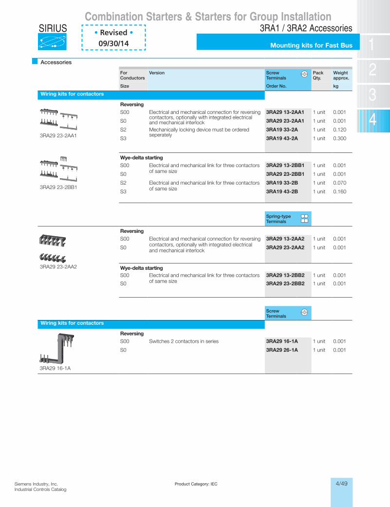
4/49Siemens Industry, Inc.Industrial Controls Catalog
SIRIUS
Product Category: IEC
Siemens / Industrial Controls Previous folio: 4/23
Accessories
For Conductors
Version Screw Terminals
Pack Qty.
Weight approx.
Size Order No. kg
Wiring kits for contactors
ReversingS00 Electrical and mechanical connection for reversing
contactors, optionally with integrated electrical and mechanical interlock
3RA29 13-2AA1 1 unit 0.001
S0 3RA29 23-2AA1 1 unit 0.001
S2 Mechanically locking device must be ordered seperately
3RA19 33-2A 1 unit 0.120
S3 3RA19 43-2A 1 unit 0.300
Wye-delta startingS00 Electrical and mechanical link for three contactors
of same size3RA29 13-2BB1 1 unit 0.001
S0 3RA29 23-2BB1 1 unit 0.001
S2 Electrical and mechanical link for three contactors of same size
3RA19 33-2B 1 unit 0.070
S3 3RA19 43-2B 1 unit 0.160
Spring-type Terminals
ReversingS00 Electrical and mechanical connection for reversing
contactors, optionally with integrated electrical and mechanical interlock
3RA29 13-2AA2 1 unit 0.001
S0 3RA29 23-2AA2 1 unit 0.001
Wye-delta startingS00 Electrical and mechanical link for three contactors
of same size3RA29 13-2BB2 1 unit 0.001
S0 3RA29 23-2BB2 1 unit 0.001
Screw Terminals
Wiring kits for contactors
ReversingS00 Switches 2 contactors in series 3RA29 16-1A 1 unit 0.001
S0 3RA29 26-1A 1 unit 0.001
Combination Starters & Starters for Group Installation3RA1 / 3RA2 Accessories
Mounting kits for Fast Bus
3RA29 23-2BB1
3RA29 23-2AA1
3RA29 23-2AA2
3RA29 16-1A
• Revised •09/30/14
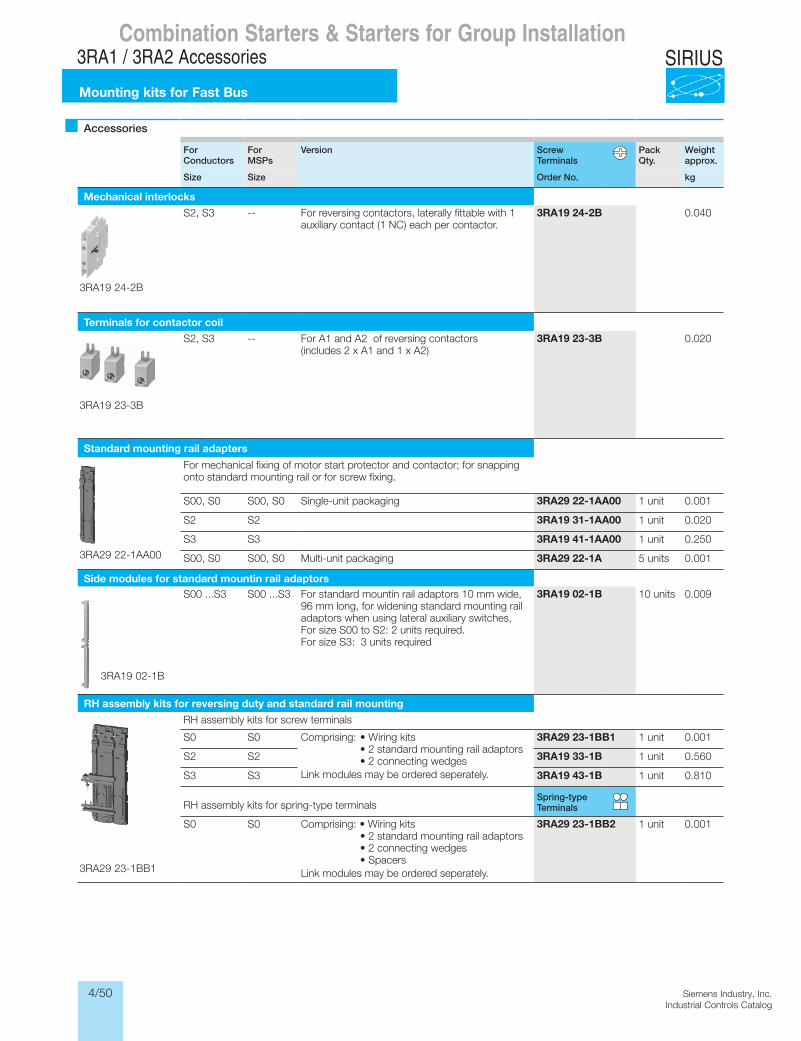
4/50 Siemens Industry, Inc.Industrial Controls Catalog
SIRIUSCombination Starters & Starters for Group Installation
3RA1 / 3RA2 Accessories
Mounting kits for Fast Bus
Accessories
For Conductors
For MSPs
Version Screw Terminals
Pack Qty.
Weight approx.
Size Size Order No. kg
Mechanical interlocks
S2, S3 -- For reversing contactors, laterally fittable with 1 auxiliary contact (1 NC) each per contactor.
3RA19 24-2B 0.040
Terminals for contactor coil
S2, S3 -- For A1 and A2 of reversing contactors (includes 2 x A1 and 1 x A2)
3RA19 23-3B 0.020
Standard mounting rail adapters
For mechanical fixing of motor start protector and contactor; for snapping onto standard mounting rail or for screw fixing.
S00, S0 S00, S0 Single-unit packaging 3RA29 22-1AA00 1 unit 0.001
S2 S2 3RA19 31-1AA00 1 unit 0.020
S3 S3 3RA19 41-1AA00 1 unit 0.250
S00, S0 S00, S0 Multi-unit packaging 3RA29 22-1A 5 units 0.001
Side modules for standard mountin rail adaptorsS00 ...S3 S00 ...S3 For standard mountin rail adaptors 10 mm wide,
96 mm long, for widening standard mounting rail adaptors when using lateral auxiliary switches, For size S00 to S2: 2 units required.For size S3: 3 units required
3RA19 02-1B 10 units 0.009
RH assembly kits for reversing duty and standard rail mounting
RH assembly kits for screw terminals
S0 S0 Comprising: • Wiring kits • 2 standard mounting rail adaptors • 2 connecting wedges Link modules may be ordered seperately.
3RA29 23-1BB1 1 unit 0.001
S2 S2 3RA19 33-1B 1 unit 0.560
S3 S3 3RA19 43-1B 1 unit 0.810
RH assembly kits for spring-type terminalsSpring-type Terminals
S0 S0 Comprising: • Wiring kits • 2 standard mounting rail adaptors • 2 connecting wedges • Spacers Link modules may be ordered seperately.
3RA29 23-1BB2 1 unit 0.001
3RA19 24-2B
3RA19 23-3B
3RA29 22-1AA00
3RA19 02-1B
3RA29 23-1BB1
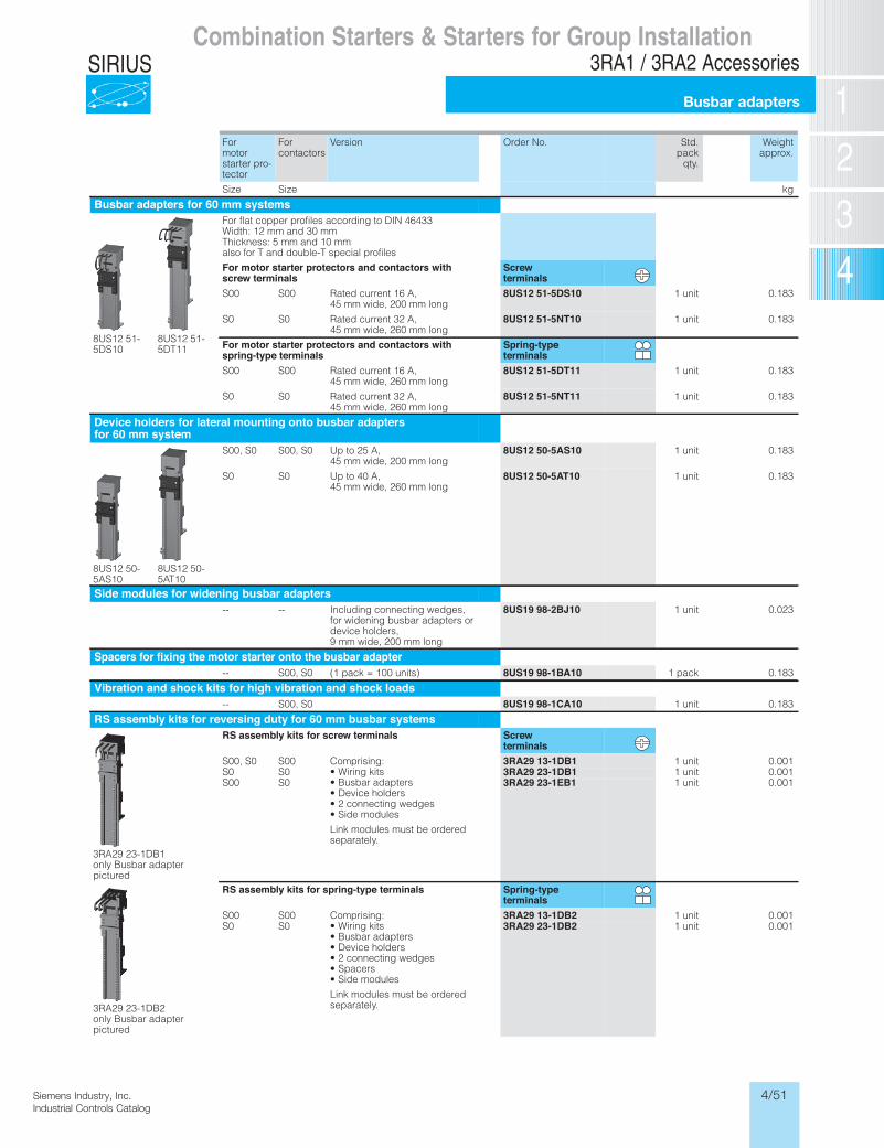
4/51Siemens Industry, Inc.Industrial Controls Catalog
SIRIUSCombination Starters & Starters for Group Installation
3RA1 / 3RA2 Accessories
Busbar adapters
Combination Starters & Starters for Group InstallationSIRIUS 3RA2 Motor Starters
Accessories
6/27SIRIUS Innovations Supplement 2012Illustrations are approximate
6
For motor starter pro-tector
For contactors
Version Order No. Std.pack
qty.
Weightapprox.
Size Size kg
Busbar adapters for 60 mm systems
8US12 51-5DS10
8US12 51-5DT11
For flat copper profiles according to DIN 46433 Width: 12 mm and 30 mm Thickness: 5 mm and 10 mmalso for T and double-T special profiles
For motor starter protectors and contactors withscrew terminals
Screwterminals
S00 S00 Rated current 16 A,45 mm wide, 200 mm long
8US12 51-5DS10 1 unit 0.183
S0 S0 Rated current 32 A,45 mm wide, 260 mm long
8US12 51-5NT10 1 unit 0.183
For motor starter protectors and contactors withspring-type terminals
Spring-typeterminals
S00 S00 Rated current 16 A,45 mm wide, 260 mm long
8US12 51-5DT11 1 unit 0.183
S0 S0 Rated current 32 A,45 mm wide, 260 mm long
8US12 51-5NT11 1 unit 0.183
Device holders for lateral mounting onto busbar adaptersfor 60 mm system
8US12 50-5AS10
8US12 50-5AT10
S00, S0 S00, S0 Up to 25 A,45 mm wide, 200 mm long
8US12 50-5AS10 1 unit 0.183
S0 S0 Up to 40 A,45 mm wide, 260 mm long
8US12 50-5AT10 1 unit 0.183
Side modules for widening busbar adapters
-- -- Including connecting wedges, for widening busbar adapters or device holders, 9 mm wide, 200 mm long
8US19 98-2BJ10 1 unit 0.023
Spacers for fixing the motor starter onto the busbar adapter
-- S00, S0 (1 pack = 100 units) 8US19 98-1BA10 1 pack 0.183
Vibration and shock kits for high vibration and shock loads
-- S00, S0 8US19 98-1CA10 1 unit 0.183
RS assembly kits for reversing duty for 60 mm busbar systems
3RA29 23-1DB1only Busbar adapter pictured
RS assembly kits for screw terminals Screwterminals
S00, S0 S00 Comprising:• Wiring kits• Busbar adapters• Device holders• 2 connecting wedges• Side modules
Link modules must be ordered separately.
3RA29 13-1DB1 1 unit 0.001S0 S0 3RA29 23-1DB1 1 unit 0.001S00 S0 3RA29 23-1EB1 1 unit 0.001
3RA29 23-1DB2only Busbar adapter pictured
RS assembly kits for spring-type terminals Spring-typeterminals
S00 S00 Comprising:• Wiring kits• Busbar adapters• Device holders• 2 connecting wedges• Spacers• Side modules
Link modules must be ordered separately.
3RA29 13-1DB2 1 unit 0.001S0 S0 3RA29 23-1DB2 1 unit 0.001
* You can order this quantity or a multiple thereof.
LV1N_06_02.fm Page 27 Saturday, October 12, 2013 6:21 PM
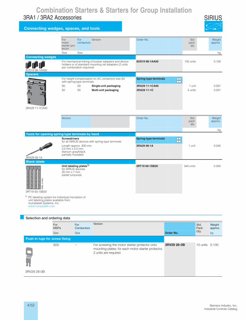
4/52 Siemens Industry, Inc.Industrial Controls Catalog
SIRIUS
Selection and ordering data
For MSPs
For Conductors
Version Std. Pack Qty.
Weight approx.
Size Size Order No. kg
Push-in lugs for screw fixing
S00 -- For screwing the motor starter protector onto mounting plates; for each motor starter protector, 2 units are required.
3RV29 28-0B 10 units 0.100
3RV29 28-0B
Combination Starters & Starters for Group Installation3RA1 / 3RA2 Accessories
Connecting wedges, spaces, and tools
Combination Starters & Starters for Group InstallationSIRIUS 3RA2 Motor Starters
Accessories
6/28 SIRIUS Innovations Supplement 2012 Illustrations are approximate
6
1) PC labeling system for individual inscription of unit labeling plates available from: murrplastik Systems, Inc. www.murrplastik.com .
For motor starter pro-tector
For contactors
Version Order No. Std.pack
qty.
Weightapprox.
Size Size kg
Connecting wedges
8US19 98-1AA00
For mechanical linking of busbar adapters and device holders or of standard mounting rail adapters (2 units per combination required)
8US19 98-1AA00 100 units 0.100
Spacers
3RA29 11-1CA00
For height compensation on AC contactors size S0 with spring-type terminals
Spring-type terminals
S0 S0 Single-unit packaging 3RA29 11-1CA00 1 unit 0.001
S0 S0 Multi-unit packaging 3RA29 11-1C 5 units 0.001
Version Order No. Weightapprox.
kg
Tools for opening spring-type terminals by hand
3RA29 08-1A
Screwdriversfor all SIRIUS devices with spring-type terminals
Spring-type terminals
Length approx. 200 mm, 3.0 mm x 0.5 mm, titanium gray/black, partially insulated
3RA29 08-1A 1 unit 0.045
Blank labels
3RT19 00-1SB20
Unit labeling plates1)for SIRIUS devices 20 mm x 7 mm, pastel turquoise
3RT19 00-1SB20 340 units 0.200
NSB
0_01429b
* You can order this quantity or a multiple thereof.
LV1N_06_02.fm Page 28 Saturday, October 12, 2013 6:21 PM
Std.pack
qty.
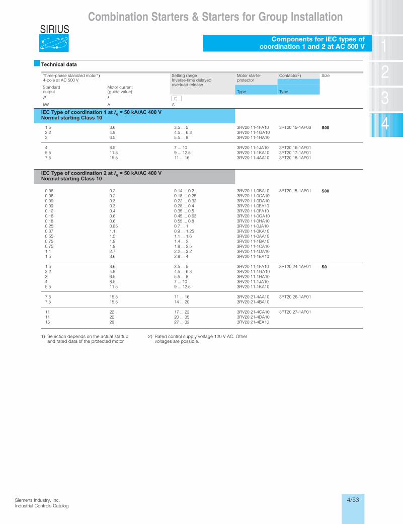
4/53Siemens Industry, Inc.Industrial Controls Catalog
SIRIUS
Siemens / Industrial Controls Previous folio: 4/24
Combination Starters & Starters for Group Installation
Components for IEC types ofcoordination 1 and 2 at AC 500 V
�Technical data
Three-phase standard motor1)4-pole at AC 500 V
Setting rangeInverse-time delayed overload release
Motor starterprotector
Contactor2) Size
Standardoutput
Motor current(guide value) Type Type
P IAAWk
IEC Type of coordination 1 at Iq = 50 kA/AC 400 V Normal starting Class 10
S003RT20 15-1AP00
3RT20 16-1AP013RT20 17-1AP013RT20 18-1AP01
3RV20 11-1FA103RV20 11-1GA103RV20 11-1HA10
3RV20 11-1JA103RV20 11-1KA103RV20 11-4AA10
3.5 ... 54.5 ... 6.35.5 ... 8
7 ... 109 ... 12.511 ... 16
3.64.96.5
8.511.515.5
1.52.23
45.57.5
S00
S0
3RT20 15-1AP01
3RT20 24-1AP01
3RT20 26-1AP01
3RT20 27-1AP01
3RV20 11-0BA103RV20 11-0CA103RV20 11-0DA103RV20 11-0EA103RV20 11-0FA103RV20 11-0GA103RV20 11-0HA103RV20 11-0JA103RV20 11-0KA103RV20 11-0AA103RV20 11-1BA103RV20 11-1CA103RV20 11-1DA103RV20 11-1EA10
3RV20 11-1FA103RV20 11-1GA103RV20 11-1HA103RV20 11-1JA103RV20 11-1KA10
3RV20 21-4AA103RV20 21-4BA10
3RV20 21-4CA103RV20 21-4DA103RV20 21-4EA10
0.14 ... 0.20.18 ... 0.250.22 ... 0.320.28 ... 0.40.35 ... 0.50.45 ... 0.630.55 ... 0.80.7 ... 10.9 ... 1.251.1 ... 1.61.4 ... 21.8 ... 2.52.2 ... 3.22.8 ... 4
3.5 ... 54.5 ... 6.35.5 ... 87 ... 109 ... 12.5
11 ... 1614 ... 20
17 ... 2220 ... 3527 ... 32
0.20.20.30.30.40.60.60.851.11.51.91.92.73.6
3.64.96.58.511.5
15.515.5
222229
0.060.060.090.090.120.180.180.250.370.550.750.751.11.5
1.52.2345.5
7.57.5
111115
IEC Type of coordination 2 at Iq = 50 kA/AC 400 VNormal starting Class 10
1) Selection depends on the actual startupand rated data of the protected motor.
2) Rated control supply voltage 120 V AC. Other voltages are possible.
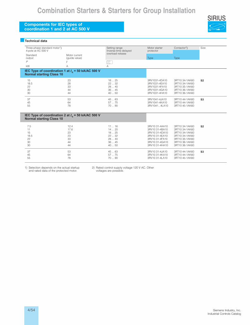
4/54 Siemens Industry, Inc.Industrial Controls Catalog
SIRIUSCombination Starters & Starters for Group Installation
Components for IEC types ofcoordination 1 and 2 at AC 500 V
�Technical data
Three-phase standard motor1)4-pole at AC 500 V
Setting rangeInverse-time delayed overload release
Motor starterprotector
Contactor2) Size
Standardoutput
Motor current(guide value) Type Type
P IAAWk
IEC Type of coordination 1 at Iq = 50 kA/AC 500 V Normal starting Class 10
S2
S3
3RT10 34-1AK603RT10 34-1AK603RT10 35-1AK603RT10 36-1AK603RT10 36-1AK60
3RT10 44-1AK603RT10 44-1AK603RT10 45-1AK60
3RV1031-4DA103RV1031-4EA103RV1031-4FA103RV1031-4GA103RV1031-4HA10
3RV1041-4JA103RV1041-4KA103RV1041...4LA10
18 ... 2522 ... 3228 ... 4036 ... 4540 ... 50
45 ... 6357 ... 7570 ... 90
2328334444
536478
1518.5223030
374555
S2
S3
3RT10 34-1AK603RT10 34-1AK603RT10 34-1AK603RT10 34-1AK603RT10 35-1AK603RT10 36-1AK603RT10 36-1AK60
3RT10 44-1AK603RT10 44-1AK603RT10 45-1AK60
3RV10 31-4AA103RV10 31-4BA103RV10 31-4DA103RV10 31-4EA103RV10 31-4FA103RV10 31-4GA103RV10 31-4HA10
3RV10 31-4JA103RV10 31-4KA103RV10 31-4LA10
11 ... 1614 ... 2018 ... 2522 ... 3228 ... 4036 ... 4540 ... 50
45 ... 6357 ... 7570 ... 90
12.417.62323334444
536478
7.5111518.5223030
374555
IEC Type of coordination 2 at Iq = 50 kA/AC 500 VNormal starting Class 10
1) Selection depends on the actual startupand rated data of the protected motor.
2) Rated control supply voltage 120 V AC. Other voltages are possible.
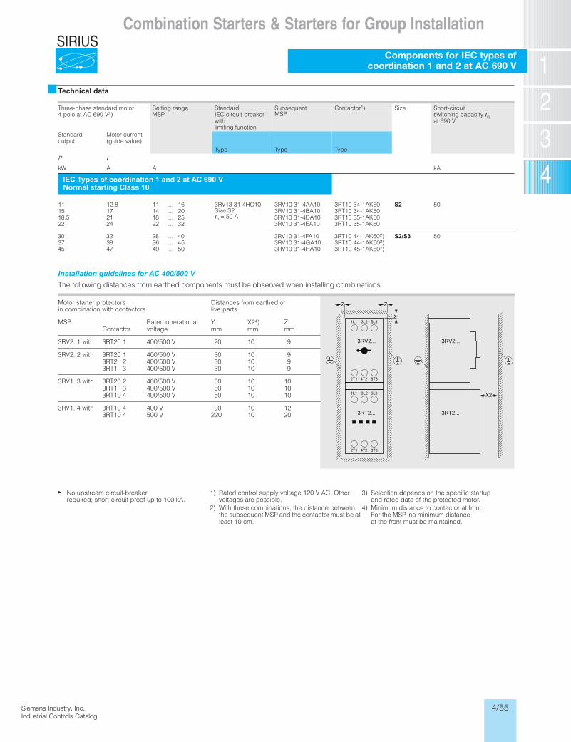
4/55Siemens Industry, Inc.Industrial Controls Catalog
SIRIUS
Siemens / Industrial Controls Previous folio: 4/25
Combination Starters & Starters for Group Installation
Components for IEC types of coordination 1 and 2 at AC 690 V
�Technical data
Three-phase standard motor 4-pole at AC 690 V3)
Setting range MSP
StandardIEC circuit-breaker withlimiting function
SubsequentMSP
Contactor1) Size Short-circuitswitching capacity Iqat 690 V
Standardoutput
Motor current(guide value)
Type Type TypeP IkW A A kA
IEC Types of coordination 1 and 2 at AC 690 VNormal starting Class 10
11 12.8 11 ... 16 3RV13 31-4HC10Size S2In = 50 A
3RV10 31-4AA10 3RT10 34-1AK60 S2 5006KA1-43 01TR301AB4-13 01VR302 ... 41715106KA1-53 01TR301AD4-13 01VR352 ... 81125.8106KA1-53 01TR301AE4-13 01VR323 ... 224222
06KA1-44 01TR301AF4-13 01VR304 ... 822303 2) S2/S3 5006KA1-44 01TR301AG4-13 01VR354 ... 639373 2)06KA1-54 01TR301AH4-13 01VR305 ... 047454 2)
Installation guidelines for AC 400/500 V The following distances from earthed components must be observed when installing combinations:
Motor starter protectors in combination with contactors
Distances from earthed orlive parts
MSPContactor
Rated operationalvoltage
Ymm
X24)mm
Zmm
3RV2. 1 with 3RT20 1 400/500 V 20 10 9
3RV2. 2 with 3RT20 13RT2 . 23RT1 . 3
400/500 V400/500 V400/500 V
303030
101010
999
3RV1. 3 with 3RT20 23RT1 . 33RT10 4
400/500 V400/500 V400/500 V
505050
101010
101010
3RV1. 4 with 3RT10 43RT10 4
400 V500 V
90220
1010
1220
No upstream circuit-breakerrequired; short-circuit proof up to 100 kA.
1) Rated control supply voltage 120 V AC. Other voltages are possible.
2) With these combinations, the distance betweenthe subsequent MSP and the contactor must be at least 10 cm.
3) Selection depends on the specific startupand rated data of the protected motor.
4) Minimum distance to contactor at front. For the MSP, no minimum distanceat the front must be maintained.
3RV2...
3RT2...
1L1 3L2 5L3
2T1 4T2 6T3
1L1 3L2 5L3
2T1 4T2 6T3
3RV2...
3RT2...
Z
Y
Z
X2
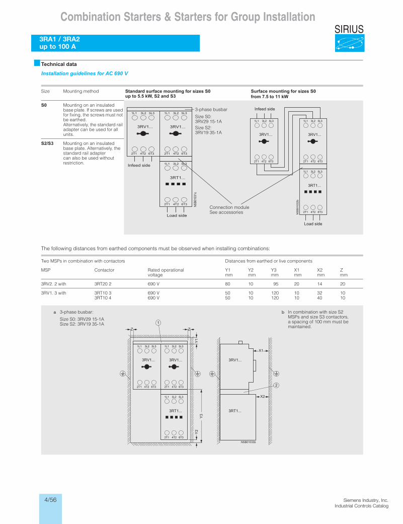
4/56 Siemens Industry, Inc.Industrial Controls Catalog
SIRIUS
Siemens / Industrial Controls Previous folio: 4/26
Combination Starters & Starters for Group Installation
3RA1 / 3RA2 up to 100 A
�Technical data
Installation guidelines for AC 690 V
Size Mounting method Standard surface mounting for sizes S0 up to 5.5 kW, S2 and S3
Surface mounting for sizes S0 from 7.5 to 11 kW
S0 Mounting on an insulated base plate. If screws are used for fixing, the screws must not be earthed.Alternatively, the standard rail adapter can be used for all units.
S2/S3 Mounting on an insulated base plate. Alternatively, the standard rail adaptercan also be used without restriction.
The following distances from earthed components must be observed when installing combinations:
Two MSPs in combination with contactors Distances from earthed or live components
MSP Contactor Rated operationalvoltage
Y1mm
Y2mm
Y3mm
X1mm
X2mm
Zmm
024102590108V 0962 02TR3htiw 2 .2VR3
3RV1. 3 with 3RT10 33RT10 4
690 V690 V
5050
1010
120120
1010
3240
1010
3-phase busbar
Size S0: 3RV29 15-1ASize S2: 3RV19 35-1A
Connection moduleSee accessories
b In combination with size S2 MSPs and size S3 contactors, a spacing of 100 mm must be maintained.
a 3-phase busbar:
Size S0: 3RV29 15-1ASize S2: 3RV19 35-1A
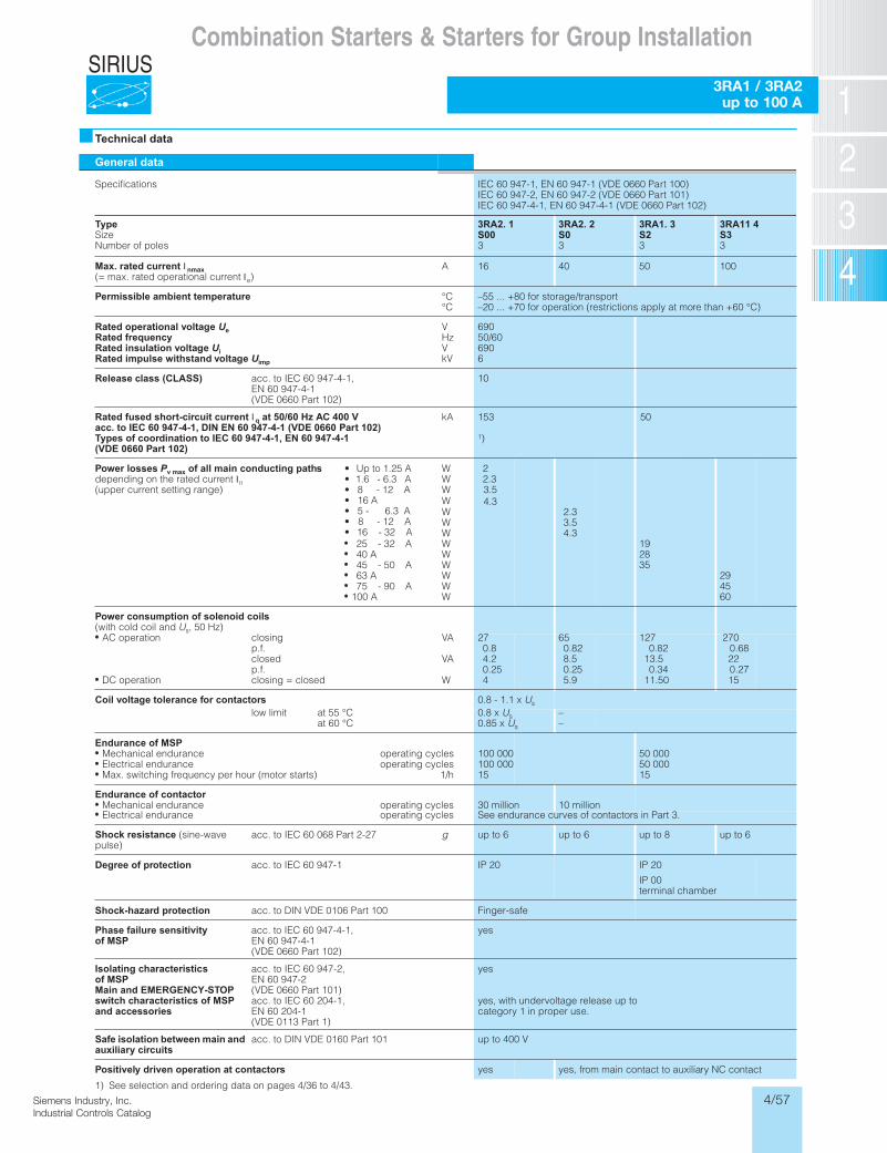
4/57Siemens Industry, Inc.Industrial Controls Catalog
SIRIUS
Siemens / Industrial Controls Previous folio: 4/27
Combination Starters & Starters for Group Installation
3RA1 / 3RA2 up to 100 A
�Technical data
General data
Specifications IEC 60 947-1, EN 60 947-1 (VDE 0660 Part 100)IEC 60 947-2, EN 60 947-2 (VDE 0660 Part 101)IEC 60 947-4-1, EN 60 947-4-1 (VDE 0660 Part 102)
TypeSizeNumber of poles
3RA2. 1S003
3RA2. 2S03
3RA1. 3S23
3RA11 4S33
Max. rated current I nmax(= max. rated operational current Ie)
A 16 40 50 100
Permissible ambient temperature °C°C
–55 ... +80 for storage/transport–20 ... +70 for operation (restrictions apply at more than +60 °C)
Rated operational voltage UeRated frequencyRated insulation voltage UiRated impulse withstand voltage Uimp
VHzVkV
69050/606906
Release class (CLASS) acc. to IEC 60 947-4-1, EN 60 947-4-1(VDE 0660 Part 102)
10
Rated fused short-circuit current I q at 50/60 Hz AC 400 V acc. to IEC 60 947-4-1, DIN EN 60 947-4-1 (VDE 0660 Part 102)Types of coordination to IEC 60 947-4-1, EN 60 947-4-1 (VDE 0660 Part 102)
kA 153 50
1)
Power losses Pv max of all main conducting pathsdepending on the rated current In(upper current setting range)
• Up to 1.25 A• 1.6 - 6.3 A• 8 - 12 A• 16 A• 5 - 6.3 A• 8 - 12 A• 16 - 32 A 25 - 32 A
40 A 45 - 50 A 63 A 75 - 90 A 100 A
WWW
WW
WWWWWWWW
22.33.54.3
2.33.54.3
192835
294560
Power consumption of solenoid coils(with cold coil and Us, 50 Hz) AC operation
DC operation
closingp.f.closedp.f.closing = closed
VA
VA
W
270.84.20.254
650.828.50.255.9
1270.82
13.50.34
11.50
2700.68220.2715
Coil voltage tolerance for contactors 0.8 - 1.1 x Us
low limit at 55 °Cat 60 °C
0.8 x Us0.85 x Us
––
Endurance of MSP Mechanical endurance Electrical endurance Max. switching frequency per hour (motor starts)
operating cyclesoperating cycles
1/h
100 000100 00015
50 00050 00015
Endurance of contactorselcyc gnitarepoecnarudne lacinahceM 30 million 10 millionselcyc gnitarepoecnarudne lacirtcelE See endurance curves of contactors in Part 3.
Shock resistance (sine-wave pulse)
acc. to IEC 60 068 Part 2-27 g up to 6 up to 6 up to 8 up to 6
Degree of protection acc. to IEC 60 947-1 IP 20 IP 20
IP 00 terminal chamber
Shock-hazard protection acc. to DIN VDE 0106 Part 100 Finger-safe
Phase failure sensitivity of MSP
acc. to IEC 60 947-4-1, EN 60 947-4-1(VDE 0660 Part 102)
yes
Isolating characteristicsof MSPMain and EMERGENCY-STOP switch characteristics of MSP and accessories
acc. to IEC 60 947-2, EN 60 947-2(VDE 0660 Part 101)acc. to IEC 60 204-1, EN 60 204-1(VDE 0113 Part 1)
yes
yes, with undervoltage release up to category 1 in proper use.
Safe isolation between main and auxiliary circuits
acc. to DIN VDE 0160 Part 101 up to 400 V
Positively driven operation at contactors yes yes, from main contact to auxiliary NC contact
1) See selection and ordering data on pages 4/36 to 4/43.
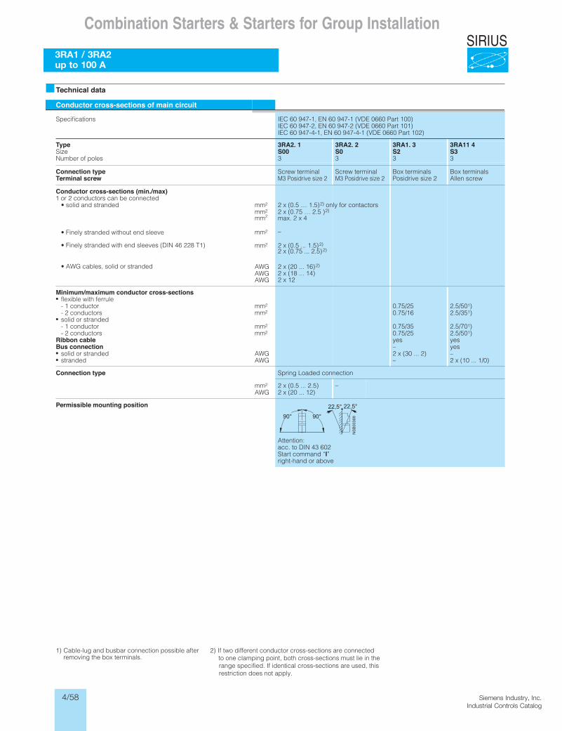
4/58 Siemens Industry, Inc.Industrial Controls Catalog
SIRIUS
Siemens / Industrial Controls Previous folio: 4/28
Combination Starters & Starters for Group Installation
3RA1 / 3RA2 up to 100 A
Technical data
Conductor cross-sections of main circuit
Specifications IEC 60 947-1, EN 60 947-1 (VDE 0660 Part 100)IEC 60 947-2, EN 60 947-2 (VDE 0660 Part 101)IEC 60 947-4-1, EN 60 947-4-1 (VDE 0660 Part 102)
TypeSizeNumber of poles
3RA2. 1S003
3RA2. 2S03
3RA1. 3S23
3RA11 4S33
Connection typeTerminal screw
Screw terminalM3 Posidrive size 2
Screw terminalM3 Posidrive size 2
Box terminalsPosidrive size 2
Box terminalsAllen screw
Minimum/maximum conductor cross-sectionsflexible with ferrule- 1 conductor- 2 conductorssolid or stranded- 1 conductor- 2 conductors
Ribbon cableBus connection
solid or strandedstranded
mm2
mm2
mm2
mm2
AWGAWG
0.75/250.75/16
0.75/350.75/25yes–2 x (30 ... 2)–
2.5/501)2.5/351)
2.5/701)2.5/501)yesyes–2 x (10 ... 1/0)
Connection type Spring Loaded connection
mm2
AWG2 x (0.5 ... 2.5)2 x (20 ... 12)
–
Permissible mounting position
Attention:acc. to DIN 43 602Start command “I”right-hand or above
1) Cable-lug and busbar connection possible after removing the box terminals.
2) If two different conductor cross-sections are connected to one clamping point, both cross-sections must lie in the range specified. If identical cross-sections are used, this restriction does not apply.
Conductor cross-sections (min./max)1 or 2 conductors can be connected
• solid and stranded mm2
mm2
mm2
mm2
mm2
AWGAWG
2 x (0.5 … 1.5)2) only for contactors2 x (0.75 … 2.5 )2)
max. 2 x 4
–
2 x (20 ... 16)2)
2 x (18 ... 14)AWG 2 x 12
2 x (0.5 ... 1.5)2)2 x (0.75 ... 2.5)2)
• AWG cables, solid or stranded
• Finely stranded with end sleeves (DIN 46 228 T1)
• Finely stranded without end sleeve
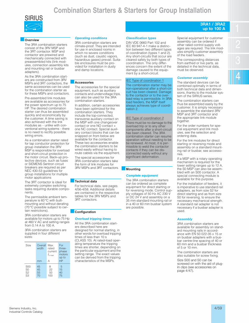
4/59Siemens Industry, Inc.Industrial Controls Catalog
SIRIUS
Siemens / Industrial Controls Previous folio: 4/29
■OverviewThe 3RA combination starters consist of the 3RV MSP and the 3RT contactor. MSP and contactor are prewired and mechanically connected with preassembled kits (link mod-ules, connection assembly kits and mounting rail or busbar adapters).As the 3RA combination start-ers are constructed from 3RV MSPs and 3RT contactors, the same accessories can be used for the combination starter as for these MSPs and contactors.Pre-assembled link modules are available as accessories for the power spectrum up to 75 HP. The desired combination starter can thus be assembled quickly and economically by the customer. A time saving is also achieved with the link modules as – unlike with con-ventional wiring systems – there is no need to rectify possible wiring errors.As a combination starter rated for tap conductor protection for group installation the 3RV MSP is responsible for overload and short-circuit protection in the motor circuit. Back-up pro-tective devices, such as fuses or SIEMENS Sentron circuit breakers are required as per NEC 430-53 guidelines for group installations for multiple motor applicationsThe 3RT contactor is ideal for extremely complex switching tasks requiring durable compo-nents.The permissible ambient tem-perature is 60 °C with butt-mounting and without derating (70 °C possible subject to cer-tain restrictions).3RA combination starters are available for motors up to 75 Hp at 460 V AC and setting ranges from 0.14 A to 100 A.3RA combination starters are supplied in four differentsizes:
Operating conditions3RA combination starters are climate-proof. They are intended for use in enclosed rooms in which no severe conditions (such as dust, caustic vapors, hazardous gases) prevail. Suita-ble enclosures must be pro-vided for installation in dusty and damp locations.
■AccessoriesThe accessories for the special equipment, such as auxiliary contacts and undervoltage trips, can also be used for the 3RA combination starters.In addition, certain accessories have been optimized for the combination starters. They include the top-connected, transverse auxiliary contact on the MSP with one changeover contact or one NO contact + one NC contact. Special auxil-iary contact blocks that can be snapped on from below are available for the contactor. These two accessories enable the combination starters to be wired easily without having to route cables via the equipment.The special accessories for 3RA combination starters take the form of link modules for 3RV MSPs and 3RT contactors.
■Technical dataFor technical data, see pages 4/56-4/58. Additional details are contained in the respective tables for the 3RV MSPs and 3RT contactors.
■Configuration
Overload tripping timesAll the 3RA combination start-ers described here are designed for normal starting, in other words for overload tripping times of less than 10 s (CLASS 10). At rated-load oper-ating temperature the tripping times are shorter, depending on the particular equipment and the setting range. The exact values can be derived from the tripping characteristics of the MSPs.
Classification typesDIN VDE 0660 Part 102 and IEC 60 947-4-1 make a distinc-tion between two different types of coordination (types 1 and 2). Any short-circuits that occur are cleared safely by both types of coordination. The only differ-ences concern the extent of the damage caused to the equip-ment by a short-circuit.
IEC Type of coordination 1The combination starter may be non-operational after a short-cir-cuit has been cleared. Damage to the contactor or to the over-load relay is permissible. In 3RA load feeders, the MSP itself always achieves type of coordi-nation 2.
IEC Type of coordination 2There must be no damage to the overload trip or to any other components after a short-circuit has been cleared. The 3RA combination starter can resume operation without needing to be be renewed. At most, it is per-missible to weld the contactorcontacts if they can be dis-connected easily without any significant deformation.
■Mounting
Complete equipmentThe 3RA combination starters can be ordered as complete equipment for direct starting or for reversing mode. Control sup-ply voltages of 50 Hz AC 230 V or DC 24 V and assembly on a 35 mm standard mounting rail or in a 40 or 60 mm busbar system are possible.
Special equipment for customer assembly can be ordered if other rated control supply volt-ages are required. The link mod-ules simplify customer assembly of the load feeders.The corresponding distances from earthed or live parts, as detailed in the technical data, must be observed.
Customer assemblyThe standard devices can be combined optimally in terms of both technical data and dimen-sions, thanks to the modular sys-tem of the SIRIUS series.The combination starters can thus be assembled easily by the customer. It is simply necessary to assemble the standard 3RVMSP and 3RT contactor and the appropriate link module together.For the order numbers for spe-cial equipment and link mod-ules, see the selection and ordering data.For the link modules for direct starting or reversing mode and assembly on a standard mount-ing rail or busbar, see accesso-ries.If a MSP with a rotary operating mechanism is required for the lower setting ranges up to 12 A, the S0 MSP can also be assem-bled with an S00 contactor. A special connecting module is available for this purpose.For the installation of feeders, it is imperative to use standard rail adapters, as from size S2 for direct starting and as from size S0 for reversing, to ensure the necessary mechanical strength. A standard rail adapter is not necessary if a busbar adapter is used.
Assembly3RA combination starters are available for assembly on stand-ard mounting rails in accord-ance with EN 50 022-35 x 15 or on busbar adapters with a bus-bar centre-line spacing of 40 or 60 mm and a busbar thickness of 5 or 10 mm.The combination starters are also suitable for screw fixing.Size S00 and S0 can be screwed on with the aid of plug-in clips (see accessories on page 4/47).
Size Overall width
Max.rated currentIn max
For three-phase motorsup to
mm A HP
S00S0S2S3
45455570
82250
100
5154075
Combination Starters & Starters for Group Installation
3RA1 / 3RA2 up to 100 A
Size S00 and S0 can be screwed on with the aid of plug- in clips (see accessories on page 4/47).
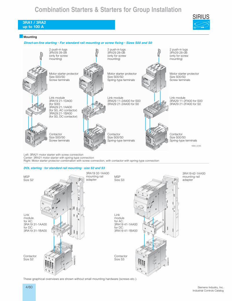
4/60 Siemens Industry, Inc.Industrial Controls Catalog
SIRIUS
Siemens / Industrial Controls Previous folio: 4/30
Combination Starters & Starters for Group Installation
3RA1 / 3RA2 up to 100 A
These graphical overviews are shown without small mounting hardware (screws etc.).
Mounting
DOL starting · for standard rail mounting · size S2 and S3
3RA19 32-1AA00 mounting railadapter
MSPSize S2
Linkmodulefor AC:3RA19 31-1AA00for DC:3RA19 31-1BA00
ContactorSize S2
3RA19 42-1AA00 mounting railadapter
MSPSize S3
Linkmodulefor AC:3RA19 41-1AA00for DC:3RA19 41-1BA00
ContactorSize S3
NSB0_02089
2 push-in lugs3RV29 28-0B(only for screwmounting)
2 push-in lugs3RV29 28-0B(only for screwmounting)
Motor starter protectorSize S00/S0Spring-type terminals
ContactorSize S00/S0Spring-type terminals
Link module3RA29 11-2AA00 for S003RA29 21-2AA00 for S0
Motor starter protectorSize S00/S0Screw terminals
ContactorSize S00/S0Spring-type terminals
Link module3RA29 11-2FA00 for S003RA29 21-2FA00 for S0
2 push-in lugs3RV29 28-0B(only for screwmounting)
Motor starter protectorSize S00/S0Screw terminals
ContactorSize S00/S0Screw terminals
Link module3RA19 21-1DA00(for S00)3RA29 21-1AA00(for S0, AC contactor)3RA29 21-1BA00(for S0, DC contactor)
Direct-on-line starting • For standard rail mounting or screw fixing • Sizes S00 and S0
Left: 3RA21 motor starter with screw connectionCenter: 3RA21 motor starter with spring-type connectionRight: Motor starter protector combination with screw connection, with contactor with spring-type connection
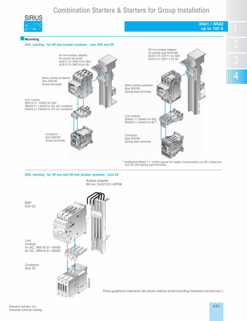
4/61Siemens Industry, Inc.Industrial Controls Catalog
SIRIUS
Siemens / Industrial Controls Previous folio: 4/31
Combination Starters & Starters for Group Installation
3RA1 / 3RA2 up to 100 A
These graphical overviews are shown without small mounting hardware (screws etc.).
�MountingDOL starting · for 60 mm busbar systems · size S00 and S0
DOL starting · for 40 mm and 60 mm busbar systems · size S2
Busbar adapter60 mm: 8US12 61-5FP08
MSPSize S2
Linkmodulefor AC: 3RA19 31-1AA00for DC: 3RA19 31-1BA00
ContactorSize S2
NS
B0_
0209
1a
60 mm busbar adapterfor screw terminals8US12 51-5DS10 for S008US12 51-5NT10 for S0
Motor starter protectorSize S00/S0Screw terminals
Link module3RA19 21-1DA00 for S003RA29 21-1AA00 for S0, AC contactor3RA29 21-1BA00 for S0, DC contactor
ContactorSize S00/S0Screw terminals
60 mm busbar adapterfor spring-type terminals8US12 51-5DT11 for S008US12 51-5NT11 for S0
Motor starter protectorSize S00/S0Spring-type terminals
Link module3RA29 11-2AA00 for S003RA29 21-2AA00 for S0
ContactorSize S00/S0Spring-type terminals
1) Additional 3RA29 11-1CA00 spacer for height compensation on AC contactors size S0 with spring-type terminals.
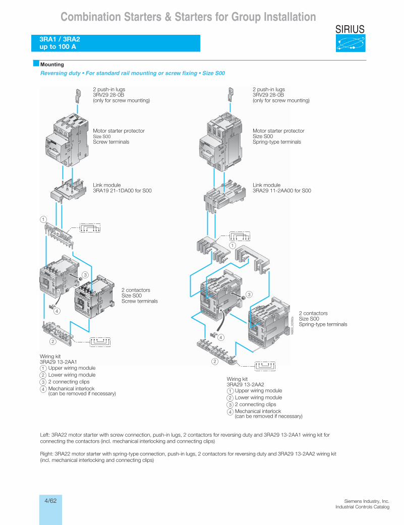
4/62 Siemens Industry, Inc.Industrial Controls Catalog
SIRIUS
Siemens / Industrial Controls Previous folio: 4/32
Combination Starters & Starters for Group Installation
3RA1 / 3RA2up to 100 A
Reversing duty • For standard rail mounting or screw fixing • Size S00
NS
B0_
0209
2a
1
3
4
1
2
3
4
2
2 push-in lugs 3RV29 28-0B(only for screw mounting)
Motor starter protectorSize S00Screw terminals
Link module3RA19 21-1DA00 for S00
2 contactorsSize S00Screw terminals
2 push-in lugs3RV29 28-0B(only for screw mounting)
Motor starter protectorSize S00Spring-type terminals
Link module3RA29 11-2AA00 for S00
2 contactorsSize S00Spring-type terminals
Wiring kit3RA29 13-2AA1
Upper wiring moduleLower wiring module2 connecting clipsMechanical interlock (can be removed if necessary)
Wiring kit3RA29 13-2AA2
Upper wiring moduleLower wiring module2 connecting clipsMechanical interlock(can be removed if necessary)
3
4
1
2
3
4
1
2
Left: 3RA22 motor starter with screw connection, push-in lugs, 2 contactors for reversing duty and 3RA29 13-2AA1 wiring kit for connecting the contactors (incl. mechanical interlocking and connecting clips)
Right: 3RA22 motor starter with spring-type connection, push-in lugs, 2 contactors for reversing duty and 3RA29 13-2AA2 wiring kit (incl. mechanical interlocking and connecting clips)
�Mounting
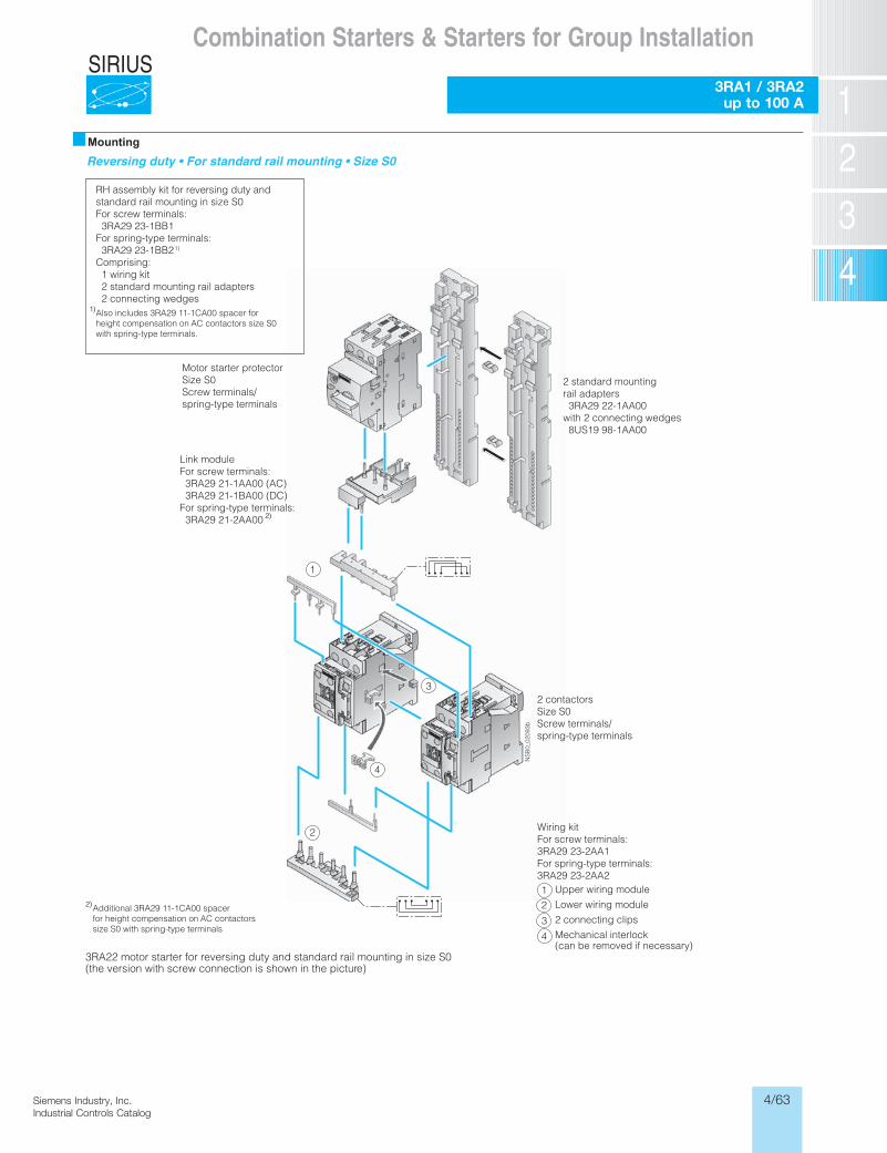
4/63Siemens Industry, Inc.Industrial Controls Catalog
SIRIUSCombination Starters & Starters for Group Installation
3RA1 / 3RA2up to 100 A
Reversing duty • For standard rail mounting • Size S0
3RA22 motor starter for reversing duty and standard rail mounting in size S0 (the version with screw connection is shown in the picture)
NS
B0_
0209
3b
3
4
1
2
Motor starter protectorSize S0Screw terminals/spring-type terminals
2 standard mounting rail adapters 3RA29 22-1AA00with 2 connecting wedges 8US19 98-1AA00
2 contactorsSize S0Screw terminals/spring-type terminals
Wiring kitFor screw terminals:3RA29 23-2AA1For spring-type terminals:3RA29 23-2AA2
Upper wiring module
Lower wiring module
2 connecting clips
Mechanical interlock(can be removed if necessary)
RH assembly kit for reversing duty andstandard rail mounting in size S0For screw terminals: 3RA29 23-1BB1For spring-type terminals: 3RA29 23-1BB21)
Comprising: 1 wiring kit 2 standard mounting rail adapters 2 connecting wedges
Link moduleFor screw terminals: 3RA29 21-1AA00 (AC) 3RA29 21-1BA00 (DC)For spring-type terminals: 3RA29 21-2AA00
Additional 3RA29 11-1CA00 spacerfor height compensation on AC contactorssize S0 with spring-type terminals
3
4
12
1)Also includes 3RA29 11-1CA00 spacer forheight compensation on AC contactors size S0with spring-type terminals.
2)
2)
�Mounting
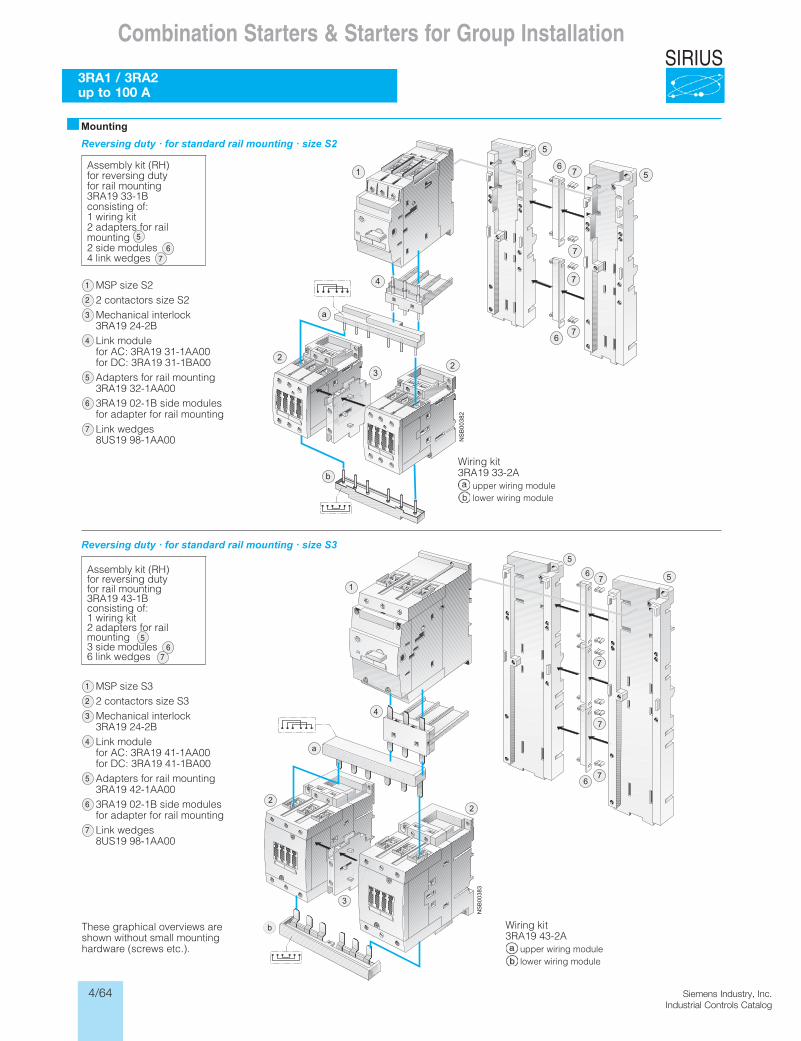
4/64 Siemens Industry, Inc.Industrial Controls Catalog
SIRIUS
Siemens / Industrial Controls Previous folio: 4/33
Combination Starters & Starters for Group Installation
3RA1 / 3RA2up to 100 A
�MountingReversing duty · for standard rail mounting · size S2
Reversing duty · for standard rail mounting · size S3
Assembly kit (RH)for reversing dutyfor rail mounting3RA19 33-1Bconsisting of:1 wiring kit2 adapters for rail mounting2 side modules 4 link wedges
MSP size S22 contactors size S2Mechanical interlock3RA19 24-2BLink modulefor AC: 3RA19 31-1AA00for DC: 3RA19 31-1BA00Adapters for rail mounting3RA19 32-1AA003RA19 02-1B side modulesfor adapter for rail mountingLink wedges8US19 98-1AA00
Wiring kit3RA19 33-2A
upper wiring modulelower wiring module
Assembly kit (RH)for reversing dutyfor rail mounting3RA19 43-1Bconsisting of:1 wiring kit2 adapters for rail mounting3 side modules 6 link wedges
MSP size S32 contactors size S3Mechanical interlock3RA19 24-2BLink modulefor AC: 3RA19 41-1AA00for DC: 3RA19 41-1BA00Adapters for rail mounting3RA19 42-1AA003RA19 02-1B side modulesfor adapter for rail mountingLink wedges8US19 98-1AA00
These graphical overviews are shown without small mounting hardware (screws etc.).
Wiring kit3RA19 43-2A
upper wiring modulelower wiring module
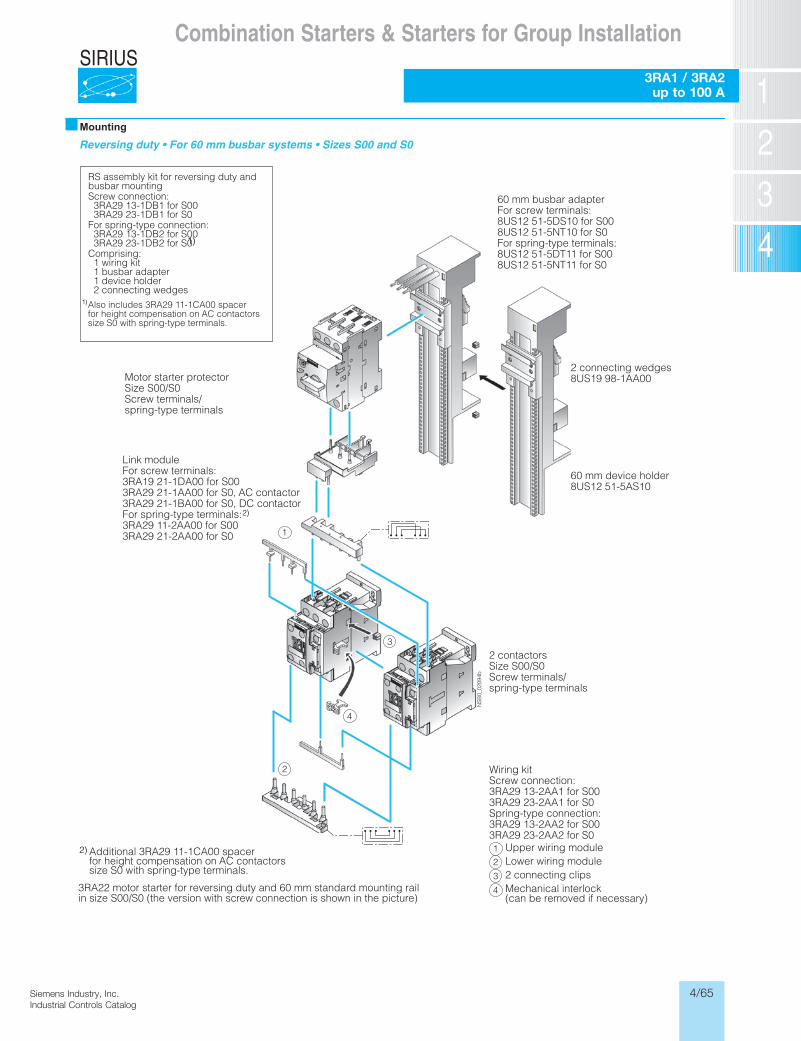
4/65Siemens Industry, Inc.Industrial Controls Catalog
SIRIUS
Reversing duty • For 60 mm busbar systems • Sizes S00 and S0
3RA22 motor starter for reversing duty and 60 mm standard mounting rail in size S00/S0 (the version with screw connection is shown in the picture)
NS
B0_
0209
4b
3
4
1
2
Motor starter protectorSize S00/S0Screw terminals/spring-type terminals
2 contactorsSize S00/S0Screw terminals/spring-type terminals
Wiring kitScrew connection:3RA29 13-2AA1 for S003RA29 23-2AA1 for S0Spring-type connection:3RA29 13-2AA2 for S003RA29 23-2AA2 for S0
Upper wiring moduleLower wiring module2 connecting clipsMechanical interlock(can be removed if necessary)
3
4
12
RS assembly kit for reversing duty andbusbar mountingScrew connection: 3RA29 13-1DB1 for S00 3RA29 23-1DB1 for S0For spring-type connection: 3RA29 13-1DB2 for S00 3RA29 23-1DB2 for S0Comprising: 1 wiring kit 1 busbar adapter 1 device holder 2 connecting wedges
Link moduleFor screw terminals:3RA19 21-1DA00 for S003RA29 21-1AA00 for S0, AC contactor3RA29 21-1BA00 for S0, DC contactorFor spring-type terminals:3RA29 11-2AA00 for S003RA29 21-2AA00 for S0
Additional 3RA29 11-1CA00 spacerfor height compensation on AC contactorssize S0 with spring-type terminals.
60 mm busbar adapterFor screw terminals:8US12 51-5DS10 for S008US12 51-5NT10 for S0For spring-type terminals:8US12 51-5DT11 for S008US12 51-5NT11 for S0
2 connecting wedges8US19 98-1AA00
60 mm device holder8US12 51-5AS10
Also includes 3RA29 11-1CA00 spacerfor height compensation on AC contactorssize S0 with spring-type terminals.
1)
1)
2)
2)
�Mounting
Siemens / Industrial Controls Previous folio: 4/34
Combination Starters & Starters for Group Installation
3RA1 / 3RA2 up to 100 A
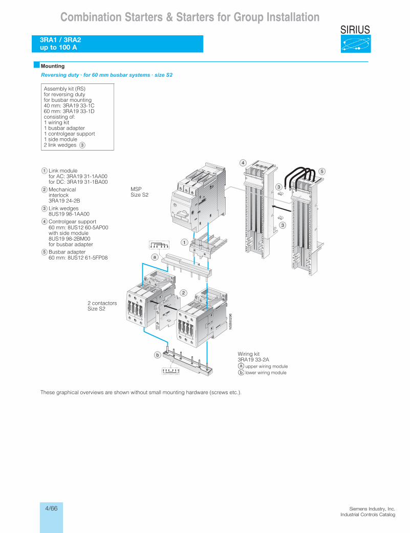
4/66 Siemens Industry, Inc.Industrial Controls Catalog
SIRIUS
Siemens / Industrial Controls Previous folio: 4/35
Combination Starters & Starters for Group Installation
3RA1 / 3RA2 up to 100 A
These graphical overviews are shown without small mounting hardware (screws etc.).
�MountingReversing duty · for 60 mm busbar systems · size S2
Assembly kit (RS)for reversing dutyfor busbar mounting40 mm: 3RA19 33-1C60 mm: 3RA19 33-1Dconsisting of:1 wiring kit1 busbar adapter1 controlgear support1 side module2 link wedges
Link modulefor AC: 3RA19 31-1AA00for DC: 3RA19 31-1BA00Mechanicalinterlock3RA19 24-2BLink wedges8US19 98-1AA00Controlgear support60 mm: 8US12 60-5AP00with side module8US19 98-2BM00for busbar adapterBusbar adapter60 mm: 8US12 61-5FP08
2 contactorsSize S2
MSPSize S2
Wiring kit3RA19 33-2A
upper wiring modulelower wiring module
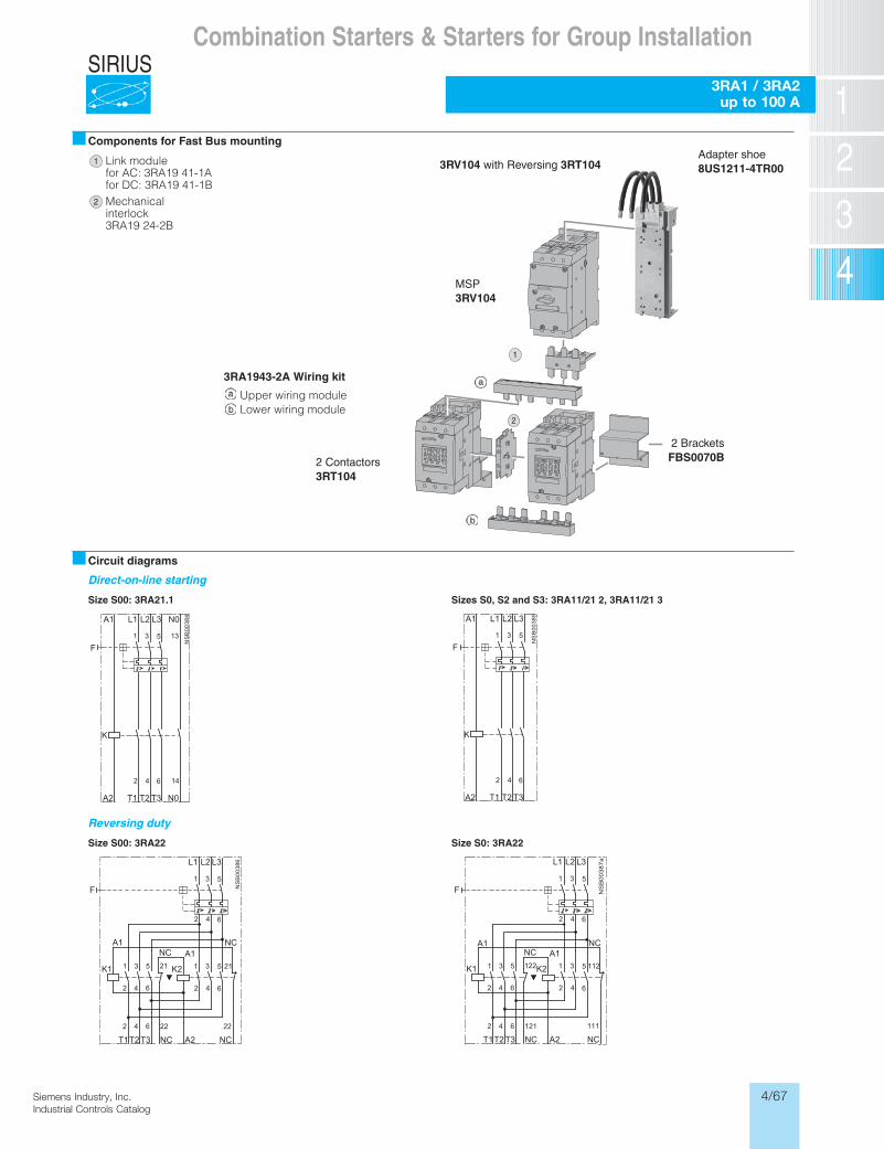
4/67Siemens Industry, Inc.Industrial Controls Catalog
SIRIUS
Siemens / Industrial Controls Previous folio: 4/36
Combination Starters & Starters for Group Installation
3RA1 / 3RA2 up to 100 A
Components for Fast Bus mounting
Circuit diagrams
Direct-on-line starting
,0S seziS 21.1AR3 :00S eziS S2 and S3: 3RA11/21 2, 3RA11/21 3
Reversing duty
22AR3 :0S eziS22AR3 :00S eziS
MSP3RV104
2 BracketsFBS0070B
Link modulefor AC: 3RA19 41-1Afor DC: 3RA19 41-1BMechanicalinterlock3RA19 24-2B
3RA1943-2A Wiring kit
Upper wiring moduleLower wiring module
2 Contactors3RT104
3RV104 with Reversing 3RT104Adapter shoe8US1211-4TR00
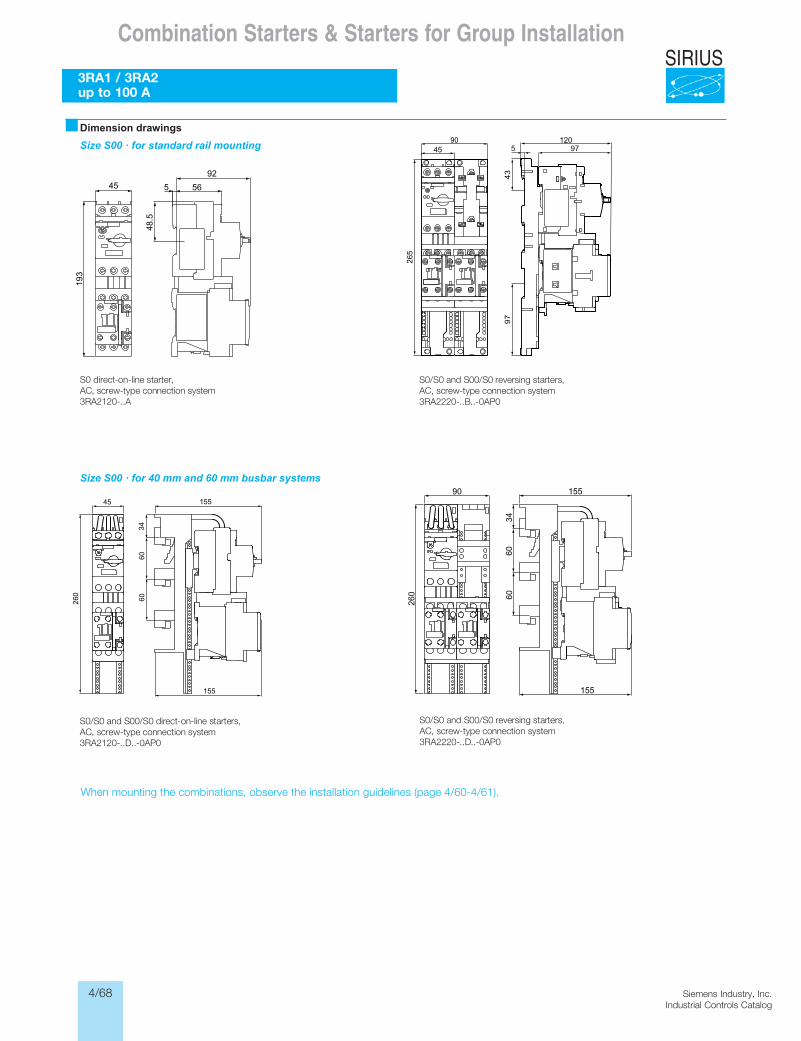
4/68 Siemens Industry, Inc.Industrial Controls Catalog
SIRIUS
Siemens / Industrial Controls Previous folio: 4/37
Combination Starters & Starters for Group Installation
3RA1 / 3RA2 up to 100 A
When mounting the combinations, observe the installation guidelines (page 4/60-4/61).
�Dimension drawingsSize S00 · for standard rail mounting
Size S00 · for 40 mm and 60 mm busbar systems
S0 direct-on-line starter, AC, screw-type connection system3RA2120-..A
S0/S0 and S00/S0 reversing starters, AC, screw-type connection system3RA2220-..B..-0AP0
S0/S0 and S00/S0 direct-on-line starters, AC, screw-type connection system3RA2120-..D..-0AP0
S0/S0 and S00/S0 reversing starters, AC, screw-type connection system3RA2220-..D..-0AP0
When mounting the combinations, observe the installation guidelines (page 4/60-4/61).
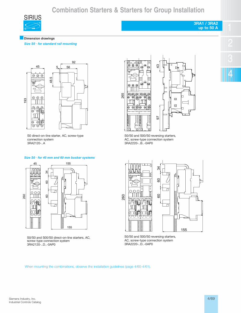
4/69Siemens Industry, Inc.Industrial Controls Catalog
SIRIUS
Siemens / Industrial Controls Previous folio: 4/39
Combination Starters & Starters for Group Installation
3RA1 / 3RA2 up to 50 A
When mounting the combinations, observe the installation guidelines (page 4/60-4/61).
■Dimension drawingsSize S0 · for standard rail mounting
Size S0 · for 40 mm and 60 mm busbar systems
S0 direct-on-line starter, AC, screw-type connection system3RA2120-..A
S0/S0 and S00/S0 reversing starters, AC, screw-type connection system3RA2220-..B..-0AP0
S0/S0 and S00/S0 direct-on-line starters, AC, screw-type connection system3RA2120-..D..-0AP0
S0/S0 and S00/S0 reversing starters, AC, screw-type connection system3RA2220-..D..-0AP0
When mounting the combinations, observe the installation guidelines (page 4/60-4/61).
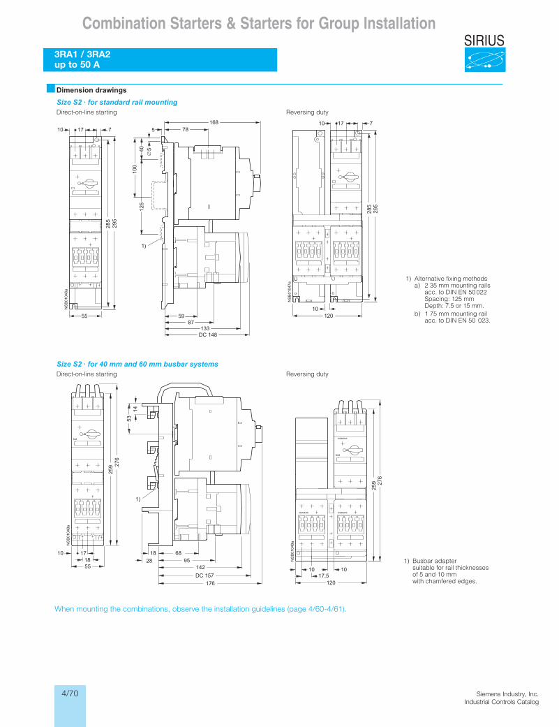
4/70 Siemens Industry, Inc.Industrial Controls Catalog
SIRIUSCombination Starters & Starters for Group Installation
3RA1 / 3RA2 up to 50 A
When mounting the combinations, observe the installation guidelines (page 4/60-4/61).When mounting the combinations, observe the installation guidelines (page 4/58).
�Dimension drawingsSize S2 · for standard rail mounting
ytud gnisreveRgnitrats enil-no-tceriD
Size S2 · for 40 mm and 60 mm busbar systemsytud gnisreveRgnitrats enil-no-tceriD
1) Alternative fixing methodsa) 2 35 mm mounting rails
acc. to DIN EN 50 022Spacing: 125 mmDepth: 7.5 or 15 mm.
b) 1 75 mm mounting railacc. to DIN EN 50 023.
1) Busbar adaptersuitable for rail thicknessesof 5 and 10 mm with chamfered edges.
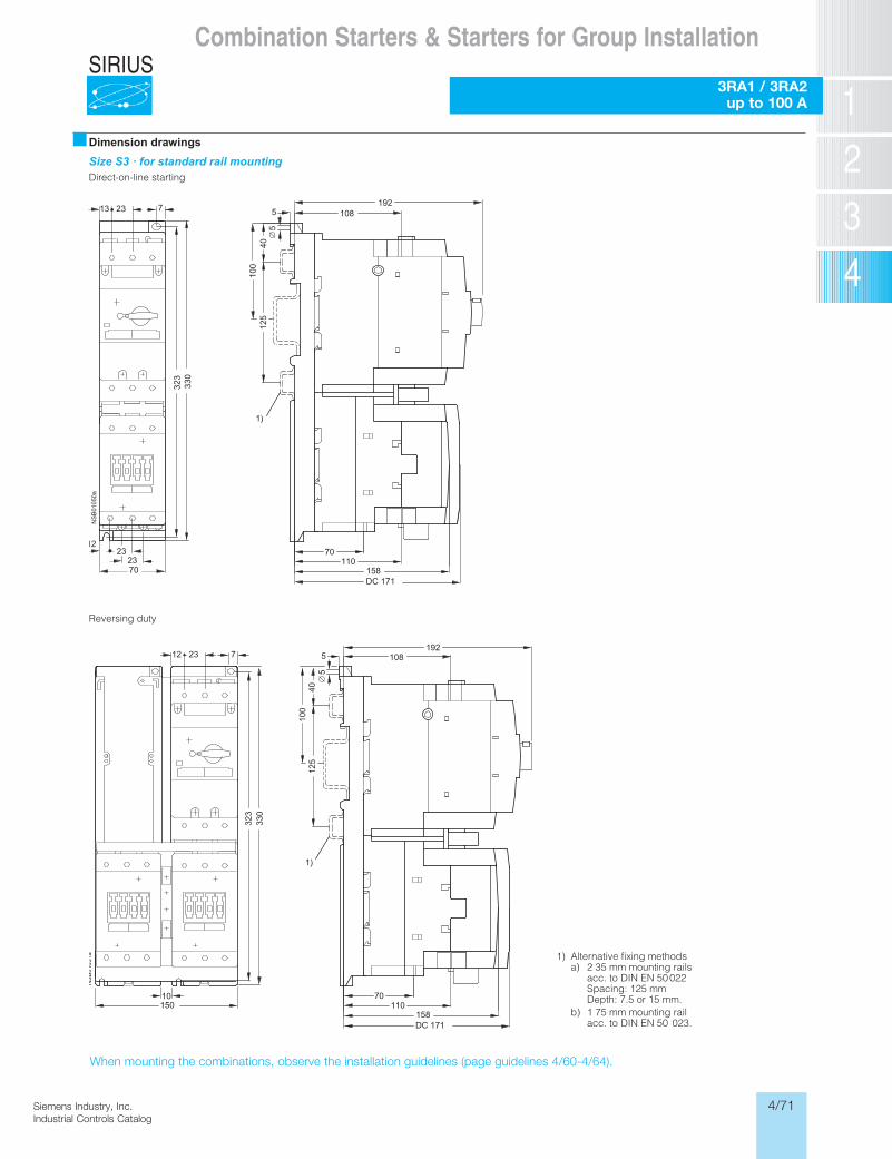
4/71Siemens Industry, Inc.Industrial Controls Catalog
SIRIUS
Siemens / Industrial Controls Previous folio: 4/40
Combination Starters & Starters for Group Installation
3RA1 / 3RA2 up to 100 A
When mounting the combinations, observe the installation guidelines (page 4/60 and 4/64).
�Dimension drawingsSize S3 · for standard rail mountingDirect-on-line starting
Reversing duty
1) Alternative fixing methodsa) 2 35 mm mounting rails
acc. to DIN EN 50 022Spacing: 125 mmDepth: 7.5 or 15 mm.
b) 1 75 mm mounting railacc. to DIN EN 50 023.
When mounting the combinations, observe the installation guidelines (page guidelines 4/60-4/64).

4/72 Siemens Industry, Inc.Industrial Controls Catalog
SIRIUSCombination Starters & Starters for Group Installation
Notes