ieee antennas and wireless propagation letters,...
TRANSCRIPT
IEEE ANTENNAS AND WIRELESS PROPAGATION LETTERS, VOL. 13, 2014 1689
Circularly Polarized S-Band Satellite Antenna WithParasitic Elements and Its Arrays
Eun-cheol Choi, Jae W. Lee, Member, IEEE, Taek-Kyung Lee, Member, IEEE, and Woo-Kyung Lee, Member, IEEE
Abstract—A structural modification of S-band turnstile antennawith cylindrical parasitic elements around a main radiator is in-troduced and investigated with respect to its gain, axial-ratio (AR)beamwidth, and radiation pattern. The overall structure is com-posed of a main radiator of two crossed bowtie-shaped dipole an-tennas and a feeding network using aWilkinson power dividerwithphase differences between two parts. A final optimization of the pa-rameter values for the enhancement of AR beamwidth is carriedout from the parametric studies. The proposed antenna has notonly a broad 5-dB AR bandwidth of 12.3% ranging from 2025 to2290 MHz, but also a stable peak gain of 7.6 dBic with circular po-larization (CP) characteristic.
Index Terms—Circular polarization (CP), parasitic element,telemetry, tracking, and command (TT&C), turnstile antenna.
I. INTRODUCTION
I N ALL satellite communications, telemetry, tracking,and command (TT&C) is an essential and fundamental
system in monitoring and controlling the status of the operatingsatellite system [1]. In order to process the information dataattained from the receiver, TT&C antennas should satisfy thegiven specification and cover the transmitting and receivingfrequency bands of and MHz,respectively. In addition, since the connection between thetransmitting and receiving signal should be maintained evenif change is due to a change of fine position, a relatively lowgain and wide beamwidth are required in the S-band satelliteantenna.According to the research for TT&C satellite antennas sat-
isfying the given specifications of transmitting and receivingenvironments, various structure candidates have been studiedand investigated. For instance, microstrip patch [2], quadrifilarhelix [3], conical spiral [4], and turnstile antenna [5]–[8] havebeen suggested and employed to transmit and receive the infor-mation data. As is well known, the microstrip antenna has itsown advantages of being lightweight, being easy to fabricate,and having robust characteristics against vibration and impactof the launching vehicle, particularly with a relatively narrow
Manuscript received June 06, 2014; accepted July 23, 2014. Date of publica-tion August 15, 2014; date of current version January 15, 2015. This work wassupported by the National Space Lab (NSL) Program under the Korea Scienceand Engineering Foundation funded by the Ministry of Education, Science andTechnology under Grant No. S10801000159-08A010015910.The authors are with the School of Electronics, Telecommunication and
Computer Engineering, Korea Aerospace University, Goyang 412-791, Korea(e-mail: [email protected]; [email protected]).Color versions of one or more of the figures in this letter are available online
at http://ieeexplore.ieee.org.Digital Object Identifier 10.1109/LAWP.2014.2347998
bandwidth being unable to cover both transmitting and re-ceiving frequencies. Also, the quadrifilar helix antenna has thedrawback of achieving a wide input impedance bandwidth overtransmitting/receiving frequencies, while with a relatively widebeamwidth and an excellent axial ratio (AR). Even the conicalspiral antenna, which is difficult to manufacture and obtain anexcellent input impedance bandwidth, has many advantagessuch as wide beamwidth and low VSWR over a relatively widebandwidth. Compared to the other types of TT&C antennas,a turnstile antenna with simplified modification schemes hasseveral attractive features in terms of easy fabrication, lowcomplexities, and robust structures. Especially, it has beenstudied that the turnstile antenna has a wide beamwidth andwide input impedance bandwidth.In this letter, we propose a turnstile S-band satellite antenna
with parasitic elements using cylindrical arrays and a powerdivider as a feeding network. By adjusting the height andoptimizing the locations and the number of cylindrical para-sitic elements surrounding the main horizontal bowtie-shapeddipoles, the target band, which is MHz coveringall the transmitting/receiving frequencies, is achieved with therequired electrical performances of 3-dB beamwidth above theaverage 85 and axial ratios under 5 dB at .In Sections II and III, the modified turnstile antenna with par-
asitic elements and its arrays is introduced with the electricalperformances using the parametric studies, parameter optimiza-tion, and verification through the measurements. The effects ofthe locations and the height of the parasitic elements on the radi-ation pattern and axial ratio will be discussed. As a conclusion,a brief summary is provided in Section IV.
II. MODIFIED TURNSTILE ANTENNA WITH PARASITICELEMENTS AND ITS ARRAYS
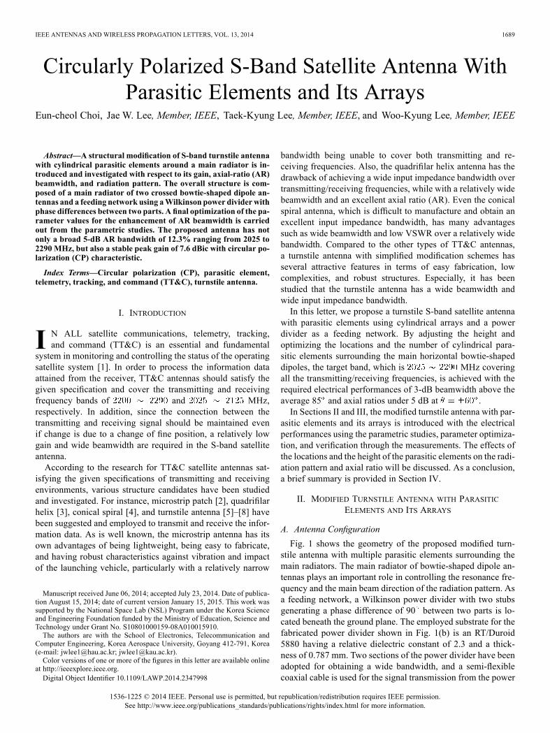
A. Antenna ConfigurationFig. 1 shows the geometry of the proposed modified turn-
stile antenna with multiple parasitic elements surrounding themain radiators. The main radiator of bowtie-shaped dipole an-tennas plays an important role in controlling the resonance fre-quency and the main beam direction of the radiation pattern. Asa feeding network, a Wilkinson power divider with two stubsgenerating a phase difference of 90 between two parts is lo-cated beneath the ground plane. The employed substrate for thefabricated power divider shown in Fig. 1(b) is an RT/Duroid5880 having a relative dielectric constant of 2.3 and a thick-ness of 0.787 mm. Two sections of the power divider have beenadopted for obtaining a wide bandwidth, and a semi-flexiblecoaxial cable is used for the signal transmission from the power
1536-1225 © 2014 IEEE. Personal use is permitted, but republication/redistribution requires IEEE permission.See http://www.ieee.org/publications_standards/publications/rights/index.html for more information.
1690 IEEE ANTENNAS AND WIRELESS PROPAGATION LETTERS, VOL. 13, 2014
Fig. 1. Proposed S-band turnstile antenna. (a) Radiator part with parasitic ele-ments (b) Feeding part on the bottom side.
Fig. 2. Radiator part. (a) Top view. (b) Side view.
divider. In order to protect the antenna from a vibration occur-ring in aerospace environments, the connection between the el-ements and the ground plane is securely made with a screw.
B. Electrical Performance and Parameter OptimizationAs shown in Fig. 2, the cylindrical parasitic elements are
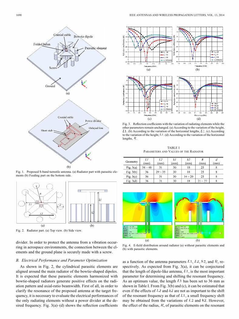
aligned around the main radiator of the bowtie-shaped dipoles.It is expected that these parasitic elements harmonized withbowtie-shaped radiators generate positive effects on the radi-ation pattern and axial-ratio beamwidth. First of all, in order toclarify the resonance of the proposed antenna at the target fre-quency, it is necessary to evaluate the electrical performances ofthe only radiating elements without a power divider at the de-sired frequency. Fig. 3(a)–(d) shows the reflection coefficients
Fig. 3. Reflection coefficients with the variation of radiating elements while theother parameters remain unchanged. (a) According to the variation of the height,. (b) According to the variation of the horizontal lengths, . (c) According
to the variation of the height, . (d) According to the variation of the horizontallengths, .
TABLE IPARAMETERS AND VALUES OF THE RADIATOR
Fig. 4. E-field distribution around radiator (a) without parasitic elements and(b) with parasitic elements.
as a function of the antenna parameters , , , and , re-spectively. As expected from Fig. 3(a), it can be conjecturedthat the length of dipole-like antenna, , is the most importantparameter for determining and shifting the resonant frequency.As an optimum value, the length has been set to 36 mm asshown in Table I. From Fig. 3(b) and (c), it can be estimated thateven if the effects of and are not as important to the shiftof the resonant frequency as that of , a small frequency shiftmay be obtained from the variations of and . However,the effect of the radius, , of parasitic elements on the resonant
CHOI et al.: CP S-BAND SATELLITE ANTENNA WITH PARASITIC ELEMENTS AND ITS ARRAYS 1691
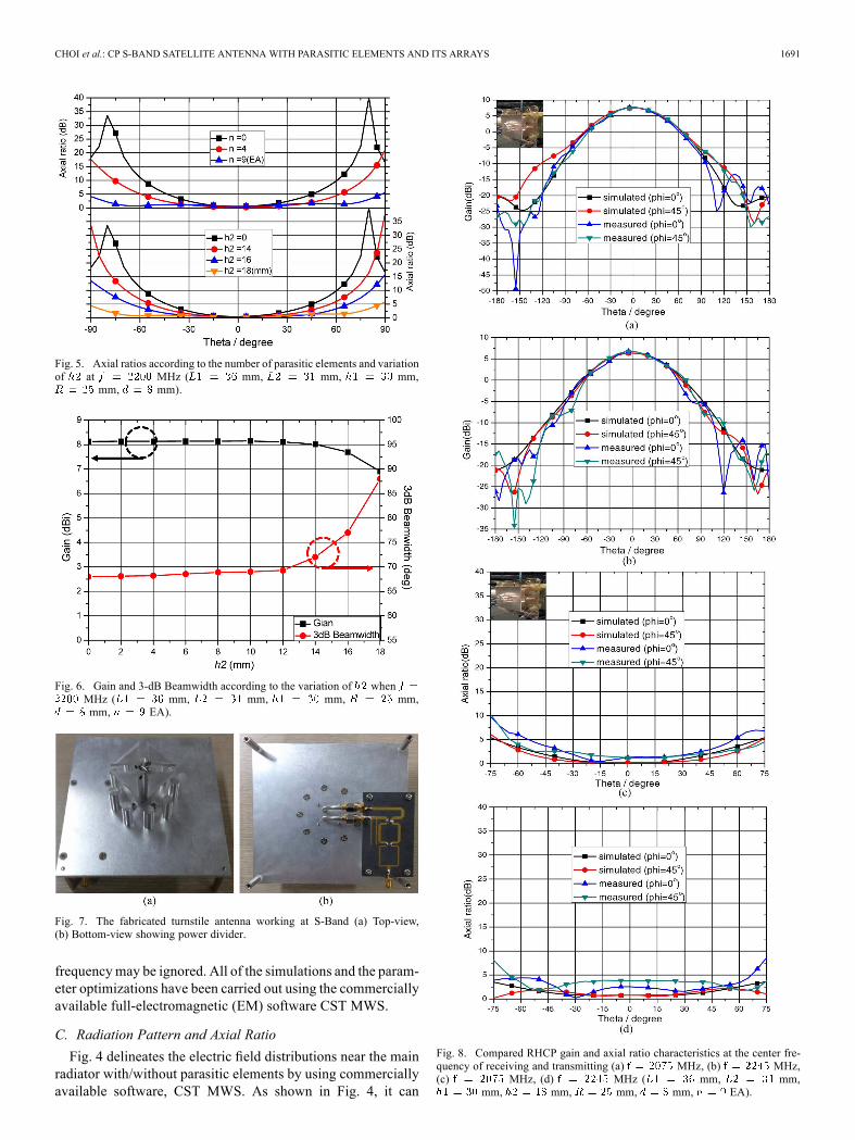
Fig. 5. Axial ratios according to the number of parasitic elements and variationof at MHz ( mm, mm, mm,
mm, mm).
Fig. 6. Gain and 3-dB Beamwidth according to the variation of whenMHz ( mm, mm, mm, mm,mm, EA).
Fig. 7. The fabricated turnstile antenna working at S-Band (a) Top-view,(b) Bottom-view showing power divider.
frequencymay be ignored. All of the simulations and the param-eter optimizations have been carried out using the commerciallyavailable full-electromagnetic (EM) software CST MWS.
C. Radiation Pattern and Axial RatioFig. 4 delineates the electric field distributions near the main
radiator with/without parasitic elements by using commerciallyavailable software, CST MWS. As shown in Fig. 4, it can
Fig. 8. Compared RHCP gain and axial ratio characteristics at the center fre-quency of receiving and transmitting (a) MHz, (b) MHz,(c) MHz, (d) MHz ( mm, mm,
mm, mm, mm, mm, EA).
1692 IEEE ANTENNAS AND WIRELESS PROPAGATION LETTERS, VOL. 13, 2014
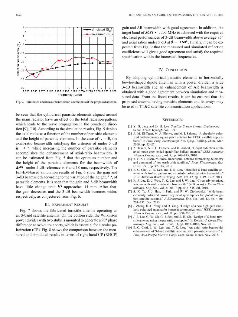
Fig. 9. Simulated andmeasured reflection coefficients of the proposed antenna.
be seen that the cylindrical parasitic elements aligned aroundthe main radiator have an effect on the total radiation pattern,which leads to the wave propagation in the broadside direc-tion [9], [10]. According to the simulation results, Fig. 5 depictsthe axial ratios as a function of the number of parasitic elementsand the height of parasitic elements. In the case of , theaxial-ratio beamwidth satisfying the criterion of under 5 dBis , while increasing the number of parasitic elementsaccomplishes the enhancement of axial-ratio beamwidth. Itcan be estimated from Fig. 5 that the optimum number andthe height of the parasitic elements for the beamwidth of
under 5 dB reference is 9 and 18 mm, respectively. Thefull-EM-based simulation results of Fig. 6 show the gain and3-dB beamwidth according to the variation of the height, , ofparasitic elements. It is seen that the gain and 3-dB beamwidthhave little change until approaches 14 mm. After that,the gain decreases and the 3-dB beamwidth becomes wider,respectively, as conjectured from Fig. 6.
III. EXPERIMENT RESULTS
Fig. 7 shows the fabricated turnstile antenna operating asan S-band satellite antenna. On the bottom side, the Wilkinsonpower divider with two stubs is mounted to generate a 90 phasedifference at two output ports, which is essential for circular po-larization (CP). Fig. 8 shows the comparison between the mea-sured and simulated results in terms of right-hand CP (RHCP)
gain and AR beamwidth with good agreement. In addition, thetarget band of MHz is achieved with the requiredelectrical performances of 3-dB beamwidth above average 85and axial ratios under 5 dB at . Finally, it can be ex-pected from Fig. 9 that the measured and simulated reflectioncoefficients will give a good agreement and satisfy the requiredspecification within the interested frequencies.
IV. CONCLUSION
By adopting cylindrical parasitic elements to horizontallybowtie-shaped dipole antennas with a power divider, a wide3-dB beamwidth and an enhancement of AR beamwidth isobtained with a good agreement between simulation and mea-sured data. From the listed results, it can be ensured that theproposed antenna having parasitic elements and its arrays maybe used in TT&C satellite communication applications.
REFERENCES
[1] Y. G. Jang and D. H. Lee, Satellite System Design Engineering.Seoul, Korea: KyungMoon, 1997.
[2] A. M. El-Tager, M. A. Eleiwa, and M. I. Salama, “A circularly polar-ized dual-frequency square patch antenna for TT&C satellite applica-tions,” in Proc. Prog. Electromagn. Res. Symp., Beijing, China, Mar.2009, pp. 23–27.
[3] A. Takacs, N. J. G. Fonseca, and H. Aubert, “Height reduction of theaxial-mode open-ended quadrifilar helical antenna,” IEEE AntennasWireless Propag. Lett., vol. 9, pp. 942–945, 2010.
[4] K. F. A. Hussein, “Conical linear spiral antenna for tracking, telemetryand command of low earth orbit satellites,” Prog. Electromagn. Res.C, vol. 291, pp. 97–107, 2012.
[5] E.-C. Choi, J. W. Lee, and T.-K. Lee, “Modified S-band satellite an-tenna with isoflux pattern and circularly polarized wide beamwidth,”IEEE Antennas Wireless Propag. Lett., vol. 12, pp. 1319–1322, 2013.
[6] K.-J. Lee, D.-J. Woo, T.-K. Lee, and J.-W. Lee, “Circularly polarizedantenna with wide axial-ratio bandwidth,” (in Korean) J. Korea Elec-tromagn. Eng. Soc., vol. 21, no. 7, pp. 842–848, Jul. 2010.
[7] S. X. Ta, J. J. Han, I. Park, and R. W. Ziolkowski, “Wide-beamcircularly polarized crossed scythe-shaped dipoles for global naviga-tion satellite systems,” J. Electromagn. Eng. Sci., vol. 13, no. 4, pp.224–232, Dec. 2013.
[8] J. Zhang, H.-C. Yang, and D. Yang, “Design of a new high-gain circu-larly polarized antenna for inmarsat communications,” IEEE AntennasWireless Propag. Lett., vol. 11, pp. 350–353, 2012.
[9] J.-S. Lee, C.-W. Oh, G.-J. Seo, and S.-H. Oh, “Design of S-band turn-stile antenna using the parasitic monopole,” (in Korean) J. Korea Elec-tromagn. Eng. Soc., vol. 17, no. 11, pp. 1083–1088, Nov. 2010.
[10] E.-C. Choi, J. W. Lee, and T.-K. Lee, “An axial ratio beamwidthenhancement of S-band satellite antenna with parasitic elements,” inProc. Asia-Pacific Microw. Conf., Coex, Seoul, Korea, Nov. 2013.