ieee luncheon-combining accurate measurement...
TRANSCRIPT

IEEE Santa Clara Valley CPMT ChapterJanuary 26, 2012
1www.cpmt.org/scv
Combining Accurate Measurement with Thermal Si l i
John WilsonApplication Engineering Manager
Simulation
Thermal Characterization of Electronic Components
pp g g gMechanical Analysis Division
January 26, 2012
Agenda
Combining Accurate Measurement with Thermal Simulation
Validated Thermal Model
JESD15-4:Delphi Compact Thermal Model (CTM)
Enhanced 2 Resistor Compact Thermal Model (CTM)— Difficulties in Junction-To-Case measurement— JESD 51-1 Electrical test method: Zth, Structure Functions— JESD51-14 Transient Dual Interface Method Overview
Use Cases:Leveraging JESD51-14 for System Thermal Design
© 2010 Mentor Graphics Corp. Company Confidentialwww.mentor.com
Summary
2 JRW, Combining Accurate Measurement with Thermal Simulation, Jan 12

IEEE Santa Clara Valley CPMT ChapterJanuary 26, 2012
2www.cpmt.org/scv
Detailed Model Validation and Delphi CTM of IC Device Packages
l
Validated 3D Thermal Model
3D Thermal Model
PackageCFD Analysis
Test Results
DELPHI Thermal Model
From Simulation
CFD (Computational Fluid Dynamics) models of packages are compared to measurements
© 2010 Mentor Graphics Corp. Company Confidentialwww.mentor.com
System CFD Analysis
are compared to measurements Validated CFD model used to generate DELPHI compact
models for system level thermal analysis Alternatively the validated 3D thermal model may be used
directly in the analysis tool
3 JRW, Combining Accurate Measurement with Thermal Simulation, Jan 12
Linking Test to System Thermal Design Compact Thermal Model
Compact Thermal Models allow:— System designers to predict device operating temperatures— Vendors to provide only thermal characteristics
CTM (Thermal Network)
CTM (Thermal Network)
CTM (Thermal Network)
CTM (Thermal Network)
CTM (Thermal Network)
e do s to p o de o y t e a c a acte st cs
© 2010 Mentor Graphics Corp. Company Confidentialwww.mentor.com4
Compact thermal models (CTM) are essential when developing a valuable predictive System Thermal Model
JRW, Combining Accurate Measurement with Thermal Simulation, Jan 12
IEEE Santa Clara Valley CPMT ChapterJanuary 26, 2012
3www.cpmt.org/scv
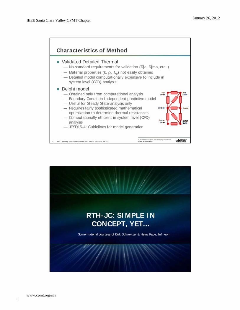
Characteristics of Method
Validated Detailed Thermal— No standard requirements for validation (Rja, Rjma, etc..) — Material properties (k C ) not easily obtainedMaterial properties (k, , Cp) not easily obtained— Detailed model computationally expensive to include in
system level (CFD) analysis
Delphi model— Obtained only from computational analysis— Boundary Condition Independent predictive model— Useful for Steady State analysis only— Requires fairly sophisticated mathematical
© 2010 Mentor Graphics Corp. Company Confidentialwww.mentor.com
— Requires fairly sophisticated mathematical optimization to determine thermal resistances
— Computationally efficient in system level (CFD)analysis
— JESD15-4: Guidelines for model generation
5 JRW, Combining Accurate Measurement with Thermal Simulation, Jan 12
RTH-JC: SIMPLE IN CONCEPT, YET...
Some material courtesy of Dirk Schweitzer & Heinz Pape, Infineon
© 2010 Mentor Graphics Corp. Company Confidentialwww.mentor.com

IEEE Santa Clara Valley CPMT ChapterJanuary 26, 2012
4www.cpmt.org/scv
Rth-JCJEDEC JESD51-1 Definition
Thermal Resistance, Junction-to-Case:
“The thermal resistance from the operating portion of aThe thermal resistance from the operating portion of a semiconductor device to outside surface of the package (case) closest to the chip mounting area when the same surface is properly heat sunk so as to minimize temperature variation across that surface.” (JESD51-1)
© 2010 Mentor Graphics Corp. Company Confidentialwww.mentor.com7 JRW, Combining Accurate Measurement with Thermal Simulation, Jan 12
Rth-JCThe Concept of Thermal Resistance
Conditions under which thermal resistance is well defined:— Heatflow between two isothermal surfaces A (T1) and B (T2).— The whole power that enters the volume V through surface A e o e po e t at e te s t e o u e t oug su ace
leaves the volume through surface B: (i.e. Pin = Pout = P)
© 2010 Mentor Graphics Corp. Company Confidentialwww.mentor.com8 JRW, Combining Accurate Measurement with Thermal Simulation, Jan 12

IEEE Santa Clara Valley CPMT ChapterJanuary 26, 2012
5www.cpmt.org/scv
Rth-JCProblems with the Definition
Neither junction nor case temperature are truly uniform— What is TJ? What is TC? Maximum, average, or … temperature?
Not all of the power dissipation P generated in the Not all of the power dissipation P generated in the junction leaves the package through the case... So:
Rth-JC is neither well-defined nor unambiguous!
? ?
© 2010 Mentor Graphics Corp. Company Confidentialwww.mentor.com9
?
JRW, Combining Accurate Measurement with Thermal Simulation, Jan 12
Fixed Case Temperature— The bottom case temperature
is kept constant
Rth-JCTwo Ways to Compute Rth-JC
s ept co sta t— Ideal heatsink case— Closest to definition as T2
is isothermal
“Floating” Case Temperature— The thermal model includes
thermal grease layer and
Fixed Case Temperature BC
© 2010 Mentor Graphics Corp. Company Confidentialwww.mentor.com
thermal grease layer and cold-plate.
— A temperature profileis allowed to developin the heatsink
— Non-ideal (physical) heatsink; realizable in practice.
10 JRW, Combining Accurate Measurement with Thermal Simulation, Jan 12

IEEE Santa Clara Valley CPMT ChapterJanuary 26, 2012
6www.cpmt.org/scv
Rth-JC Comparison of Rth-JC Boundary Conditions
Fixed Case Temperature— Rth-JC = 3.12K / 5W
= 0.624 K/W 0.624 K/W
Floating Case Temperature— Rth-JC = 2.66K / 5W
= 0.531 K/W
© 2010 Mentor Graphics Corp. Company Confidentialwww.mentor.com11 JRW, Combining Accurate Measurement with Thermal Simulation, Jan 12
Rth-JCComparing Modeling & Measurement
Labs measure values even higher than Fixed Case Rth-JC:
Rth-JC measurements (thermocouple method)
of a MOSFET in a D2PAK package
Fixed Case Rth-JC
SimulationFloating Case Rth-JC Simulation
© 2010 Mentor Graphics Corp. Company Confidentialwww.mentor.com12
u a o
Typical Effective Coldplate htc
JRW, Combining Accurate Measurement with Thermal Simulation, Jan 12

IEEE Santa Clara Valley CPMT ChapterJanuary 26, 2012
7www.cpmt.org/scv
Rth-JCThermocouple Issues
The reason has been thoroughly investigated by Infineon.— There is a temperature gradient downThere is a temperature gradient down
the thermocouple bead— The TC drill hole also affects the
temperature in the coldplate
© 2010 Mentor Graphics Corp. Company Confidentialwww.mentor.com13 JRW, Combining Accurate Measurement with Thermal Simulation, Jan 12
Rth-JC Conclusions
Rth-JC appears conceptually simple, but
It’s definition is somewhat ambiguous, and
It’s very tricky to measure:— Thermocouple measurement tends to overestimate Rth-JC— Thermal simulations predict a possible measurement error of 50%
and more!— This might explain why the TC-measurement often returns Rth-JC
values which are (much) higher than those obtained by simulation
© 2010 Mentor Graphics Corp. Company Confidentialwww.mentor.com14 JRW, Combining Accurate Measurement with Thermal Simulation, Jan 12

IEEE Santa Clara Valley CPMT ChapterJanuary 26, 2012
8www.cpmt.org/scv
BRIEF DISCUSSION ON ELECTRICAL TEST METHOD
© 2010 Mentor Graphics Corp. Company Confidentialwww.mentor.comJRW, Combining Accurate Measurement with Thermal Simulation, Jan 12
Transient Test MethodsImplementing The Electrical Test Method
The JESD51-1 standard lists two modes of measurement:
Dynamic mode - pulsed heating
Static mode - continuous heating
Both methods rely on using a Temperature Sensitive Parameter (TSP) t l t lt t
© 2010 Mentor Graphics Corp. Company Confidentialwww.mentor.com
(TSP) to relate voltage to temperature, e.g.:— Voltage drop across a forward-biased
diode.
16 JRW, Combining Accurate Measurement with Thermal Simulation, Jan 12

IEEE Santa Clara Valley CPMT ChapterJanuary 26, 2012
9www.cpmt.org/scv
Transient Test MethodsJEDEC “Static” Test Method
Switch power on (or off) in initial steady state and wait
While waiting for final steady state, measure (record) the l l k l
TR
P1
P2
t
P
∆PThermal transient response curve
final steady-stateT temperature rise
real transient continuously, as it takes place.
© 2010 Mentor Graphics Corp. Company Confidentialwww.mentor.com
P
TRthJA
T
t
T2
T1
∆T
log t time
initial steady-state
17 JRW, Combining Accurate Measurement with Thermal Simulation, Jan 12
Analyzing the Structure
Test output can be mathematically processed to determine the “Structure Function”— Identify the thermal resistances and capacitances along theIdentify the thermal resistances and capacitances along the
heat transfer path
© 2010 Mentor Graphics Corp. Company Confidentialwww.mentor.com
Test output Structure Function(Cth vs Rth)
18 JRW, Combining Accurate Measurement with Thermal Simulation, Jan 12

IEEE Santa Clara Valley CPMT ChapterJanuary 26, 2012
10www.cpmt.org/scv
Structure Function: Why is it important?
Consider a Cu rod of 1x1mm2 cross-sectional area— Rod 1: 100mm (, Cv)— Rod 2: 40mm (, Cv), 20mm (, 2xCv), 40mm (, Cv)Rod 2: 40mm (, Cv), 20mm (, 2xCv), 40mm (, Cv)
150
200
250
era
ture
ris
e [°
C]
T3Ster Master: Smoothed response
rod_END_tr - Ch. 0rod2_END_tr - Ch. 0
Rth_tot 250K/W
© 2010 Mentor Graphics Corp. Company Confidentialwww.mentor.com
1e-6 1e-4 0.01 1 100 100000
50
100
Time [s]
Te
mp
e
19 JRW, Combining Accurate Measurement with Thermal Simulation, Jan 12
Structure Function: Why is it important? The difference in the structures is well seen
T3Ster Master: cumulative structure function(s)
99.5752 49.7876
0.15
0.2
0.25
0.3
0.35
0.4
Cth
[W
s/K
]
0.135285
rod_END_tr - Ch. 0rod2_END_tr - Ch. 0
© 2010 Mentor Graphics Corp. Company Confidentialwww.mentor.com
50 100 150 2000
0.05
0.1
Rth [K/W]
0.142323
20 JRW, Combining Accurate Measurement with Thermal Simulation, Jan 12

IEEE Santa Clara Valley CPMT ChapterJanuary 26, 2012
11www.cpmt.org/scv
MEASURING RTH-JCTRANSIENT DUAL THERMAL
INTERFACE METHOD (JESD51-14)Some material courtesy of Dirk Schweitzer & Heinz Pape, Infineon
© 2010 Mentor Graphics Corp. Company Confidentialwww.mentor.com
y p ,
Transient Dual Interface (TDI) Method Background: Original Approach by MicReD
Original approach pioneeredby MicReD:— P Szabo et al Proc 10thP. Szabo et. al., Proc. 10th
THERMINIC, 2004
© 2010 Mentor Graphics Corp. Company Confidentialwww.mentor.com22 JRW, Combining Accurate Measurement with Thermal Simulation, Jan 12

IEEE Santa Clara Valley CPMT ChapterJanuary 26, 2012
12www.cpmt.org/scv
Transient Dual Interface (TDI) Method Background: Original Approach by MicReD
Proposed approach used comparison of ‘structure functions’ to determine Rth JCfunctions to determine Rth-JC
© 2010 Mentor Graphics Corp. Company Confidentialwww.mentor.com23
Rth-JC 0.35K/W
JRW, Combining Accurate Measurement with Thermal Simulation, Jan 12
Transient Dual Interface (TDI) Method Background: Original Approach by MicReD
Peaks and valleys of differential structure function correspond to different layers of the heatflow path.— Interface surfaces represented by inflexion pointsInterface surfaces represented by inflexion points.— Rth-JC can be identified as the first inflexion point following the
separation of the structure functions
Structure functions should in principle be identical as long as the heat flow paths are equal...
© 2010 Mentor Graphics Corp. Company Confidentialwww.mentor.com
BUT: Identical path in both measurements includes first grease layer— structure functions might separate “too late” as it will be after the
glue layer.
24 JRW, Combining Accurate Measurement with Thermal Simulation, Jan 12

IEEE Santa Clara Valley CPMT ChapterJanuary 26, 2012
13www.cpmt.org/scv
Transient Dual Interface (TDI) Method Background: Infineon Proposal
Perform two Zth-measurements on the same device:same device:— Without thermal grease:
© 2010 Mentor Graphics Corp. Company Confidentialwww.mentor.com
— With thermal grease:
25 JRW, Combining Accurate Measurement with Thermal Simulation, Jan 12
Transient Dual Interface (TDI) Method Background: Infineon Proposal
Infineon proposed an alternative evaluation method based on themethod based on the separation point of the Zth-curves instead of the structure functions
Found strong correlation between Zth-value Zth(tS) and Rth JC*:
© 2010 Mentor Graphics Corp. Company Confidentialwww.mentor.com
and Rth-JC*:
26
* Not valid for devices with an internal heat flow barrier such as a low conductivity glue, where the structure function approach works better.
JRW, Combining Accurate Measurement with Thermal Simulation, Jan 12
IEEE Santa Clara Valley CPMT ChapterJanuary 26, 2012
14www.cpmt.org/scv
Transient Dual Interface (TDI) MethodSummary
JESD51-14 has a number of advantages over the original MIL-Std 883 1983 which sufferedStd 883 1983, which suffered from:— Low reproducibility:— Thermocouple bead not sufficiently
insulated from cold plate— High clamping pressure causes
delaminations within the package— Influence of thermocouple drill hole
© 2010 Mentor Graphics Corp. Company Confidentialwww.mentor.com
Influence of thermocouple drill hole
But:— Result interpretation is not so
straightforward without dedicated software.
27 JRW, Combining Accurate Measurement with Thermal Simulation, Jan 12
LEVERAGING TEST FOR SYSTEM THERMAL DESIGN
© 2010 Mentor Graphics Corp. Company Confidentialwww.mentor.com

IEEE Santa Clara Valley CPMT ChapterJanuary 26, 2012
15www.cpmt.org/scv
Measurement-Based Modeling of Power Semiconductor Packages
JESD51-14Structure Function
Model Creation
© 2010 Mentor Graphics Corp. Company Confidentialwww.mentor.com
Analysis Software
JESD51-14 compliant RthJC measurements are converted into compact thermal models and used in
analysis software.29 JRW, Combining Accurate Measurement with Thermal Simulation, Jan 12
QA
First and Unique Measurement and Automatic Modeling of LED Components
Structure Function
Thermal Measurements Processed
Delamination from the MCPCB: a Failure
JESD15-14
LED Component Measured for Thermal Characteristics and Light Output
Thermal Model Created
© 2010 Mentor Graphics Corp. Company Confidentialwww.mentor.com
Analysis Software
System Thermal SimulationSub-System Thermal Simulation
30 JRW, Combining Accurate Measurement with Thermal Simulation, Jan 12

IEEE Santa Clara Valley CPMT ChapterJanuary 26, 2012
16www.cpmt.org/scv
Summary
Validated Detailed Model— Difficult to obtain the necessary material thermal properties— Time required to obtain properties makes it prohibitive to use in
design— Computationally prohibitive to use in system level CFD analysis
Delphi— Only applicable to steady state analysis (resistances)— Not able to predict performance for different power profiles or
failure conditions— Computationally efficient
Dynamic Modified 2R Compact Thermal Model
© 2010 Mentor Graphics Corp. Company Confidentialwww.mentor.com
Dynamic Modified 2R Compact Thermal Model— Validated compact model based on JESD51-14, without developing
validated detailed analysis model— Captures transient behaviour of device— Computationally efficient
31 JRW, Combining Accurate Measurement with Thermal Simulation, Jan 12
© 2010 Mentor Graphics Corp. Company Confidentialwww.mentor.comYour Initials, Presentation Title, Month Year32