ieee pes boston chapter protection engineering course...
TRANSCRIPT

Symmetrical ComponentsSymmetrical Components
IEEE PES Boston Chapter
Protection Engineering Course SeriesFall 2013Fall 2013
Instructor: Dean V. Sorensen (National Grid)
Symmetrical ComponentsDiscussion Topics
• History and Description
p
• The General Method of Symmetrical Components – N-Phase Systems
3 Ph S t– 3-Phase Systems
• Circuit Element Sequence Representations
• Fault Analysis Using Symmetrical Components
_______________________________________1J. Lewis Blackburn and Thomas J. Domin, Protective Relaying Principles and Applications, 3rd Ed., CRC Press, 2007.2John, A Horak, Derivation of Symmetrical Component Theory and Symmetrical Component Networks, Georgia Tech protecti e Rela ing Conference Atlanta GA April 2005 http // basler com/do nloads/S mmcomp pdf
Fall 2013Dean V. Sorensen
Symmetrical Components 2
protective Relaying Conference, Atlanta, GA, April 2005, http://www.basler.com/downloads/Symmcomp.pdf

Symmetrical Components – History and Description
• The method of symmetrical components provides a tool to study systems with unbalanced phasors.
• Developed by Charles Fortescue in 1913, who presented a paper entitled’ “Method of Symmetrical Co-ordinates Applied to the Solution of Polyphase Networks.”3
• In mathematics terms, it is a linear transformation4 mapping quantities (ABC) from a physical domain into quantities (012) in a sequence domain.
• Simplifies circuit analysis of a three-phase mutually coupled circuit bySimplifies circuit analysis of a three phase mutually coupled circuit by transforming it into 3 single phase circuits with no mutual coupling.
_______________________________________
3Fortescue’s paper is available at http://thunderbox.uwaterloo.ca/~ccanizar/papers/classical/Fortescue.pdffrom the University of Waterloo.
4Rowland, Todd and Weisstein, Eric W. "Linear Transformation." From MathWorld—A Wolfram Web R htt // th ld lf /Li T f ti ht l
Fall 2013Dean V. Sorensen
Symmetrical Components 3
Resource http://mathworld.wolfram.com/LinearTransformation.html

A Tool for Simplifying Fault Analysis
• A balanced system is easily analyzed becauseeasily analyzed because only one phase needs to be considered.
• Unbalanced systems require a full circuit analysis of all three phases, neutral and ground elements.
• Therefore transforming an unbalanced system intounbalanced system into balanced systems promises to simplify our analysis
Fall 2013Dean V. Sorensen
Symmetrical Components 4

The General Method of Symmetrical Components
• The use of symmetrical components for three-phase power system analysis is a subset of a more general transformation method. The general method resolves Nunbalanced phasors which share the same reference plane into N sets of balanced h h f hi h h N bphasors, each of which has N members.
• Within each set, each of the phasors has the same magnitude and successive phases have the same phase angle separation between them.
• Let α be the angle between phases in an N-phase system. Then let’s define a useful operator dubbed the “a” operator. The “a” operator is a unit phasor (magnitude = 1) with an angle equal to α. Multiplying a phasor by a simply rotates that phasor by α degrees in the counterclockwise direction.
N°= 360α α∠=1a Rotation operator
• Within each sequence network, the angular displacement of successive phasors is -α·n where n is the phase sequence network number and where n = 0, 1, 2, …N-1.
Fall 2013Dean V. Sorensen
Symmetrical Components 5

3-Phase System Example
Note: All system rotation, even “negative-sequence” phasors, is counterclockwise!
Fall 2013Dean V. Sorensen
Symmetrical Components 6
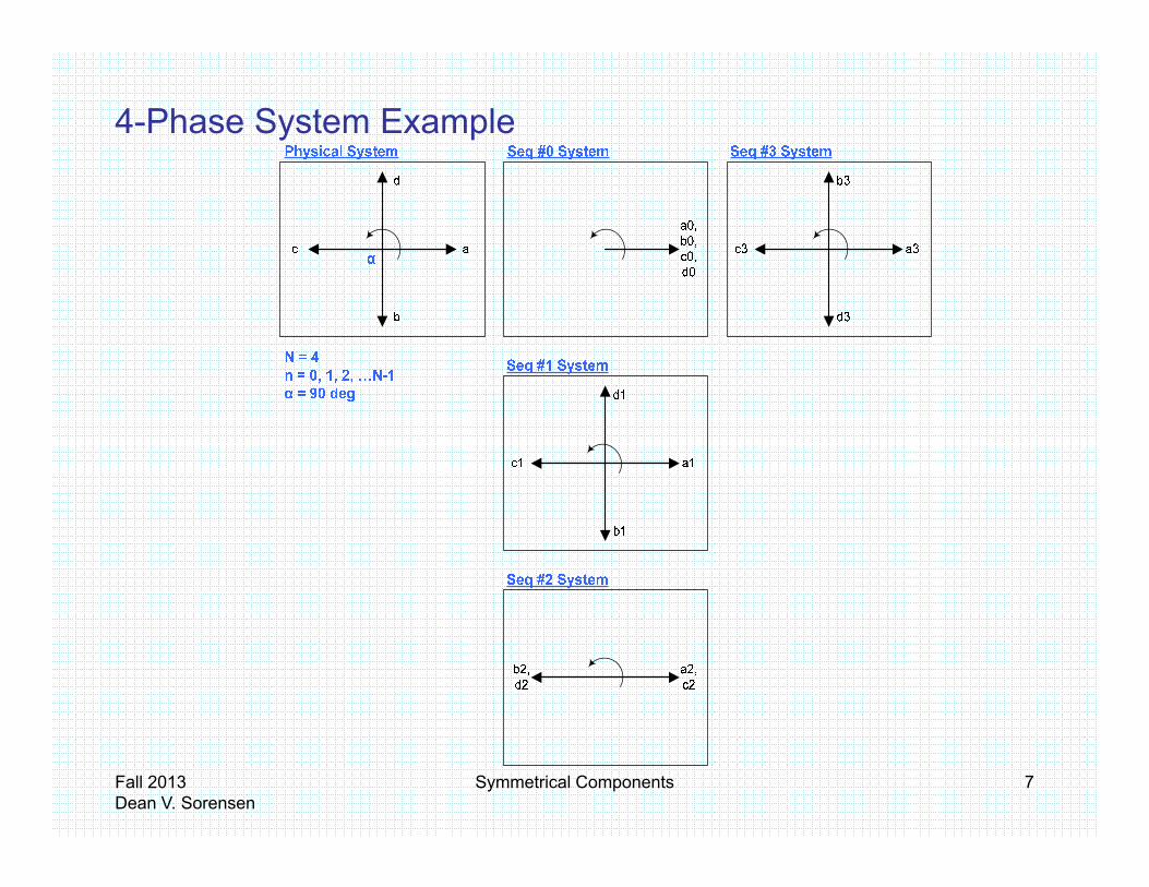
4-Phase System Example
Fall 2013Dean V. Sorensen
Symmetrical Components 7

5-Phase System Example
Fall 2013Dean V. Sorensen
Symmetrical Components 8

6-Phase System Example
Trivia Factoid:
When N is prime, each set where n>0 will form a regular N-sided polygon. Consider n=0 as being a 1-sided polygon. For N=6, prime factors are 1, 2,
A more detailed fault analysis and development of 6-phase
3 and 6. Can you find a 1-sided, 2-sided, 3-sided and 6-sided polygon among these sets? Try this for any value of N.
sequence network applications can be found in the following paper:
5Bhatt, Navin B., Six-Phase (Multi-Phase) Power Transmission Systems: Fault Analysis, IEEE Transactions on Power
Fall 2013Dean V. Sorensen
Symmetrical Components 9
y yApparatus and Systems, Vol. PAS-96, No. 3, May/June 1977, http://www.libsou.com/pdf/01601991.pdf

Back to the 3-Phase System Example
VVVV ++=
We can relate physical domain quantities to sequence domain quantities by superposition.
210
210
210
cccc
bbbb
aaaa
VVVVVVVVVVVV
++=++=++=
This transforms 3 quantities into a total of 9 quantities.
We can then define quantities V0 V1 and V2 in the sequence
Simplified?
We can then define quantities V0, V1 and V2 in the sequence domain using a-phase (or specifically Va) as a reference and along with the “a” operator substitute the new “sequence” quantities into b and c-phases.
11
00
a
a
VVVVVV
===
221
20
210
VaaVVVaVVaVV
VVVV
b
a
++=
++=
++=
Fall 2013Dean V. Sorensen
Symmetrical Components 10
22 aVV = 210 VaaVVVc ++=
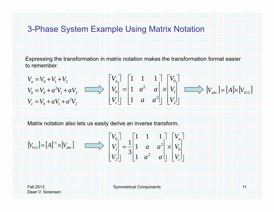
3-Phase System Example Using Matrix Notation
Expressing the transformation in matrix notation makes the transformation format easier to remember
212
0
210
aVVaVVVVVV
b
a
++=
++=
×
=
1
021
111VV
aaVV
b
a
[ ] [ ] [ ]012VAVabc ×=
to remember.
22
10
210
VaaVVVc
b
++=
2
121 VaaVc
b [ ] [ ] [ ]012abc
Matrix notation also lets us easily derive an inverse transform.
[ ] [ ] [ ]bVAV ×= −1
×
=
a
VV
aaVV
20
1111
1[ ] [ ] [ ]abcVAV ×=012
×
=
c
b
VV
aaaa
VV
22
1
11
3
Fall 2013Dean V. Sorensen
Symmetrical Components 11

3-Phase System Example Using Matrix Notation
Naturally, current phasors will have the same transformation form as voltage phasors.
212
0
210
aIIaIIIIII
b
a
++=
++=
×
=
1
021
111II
aaII
b
a
[ ] [ ] [ ]IAI ×=2
210 IaaIIIc ++=
2
121 IaaIc
b [ ] [ ] [ ]012IAIabc ×=
[ ] [ ] [ ]abcIAI ×= −1012
×
=
b
a
III
aaaa
III
2
21
0
11
111
31
cIaaI2 1
Fall 2013Dean V. Sorensen
Symmetrical Components 12

Symmetrical Component Transformation Worked Example
Fall 2013Dean V. Sorensen
Symmetrical Components 13
6This example is from Washington State University’s March 2011 Hands-On Relay School
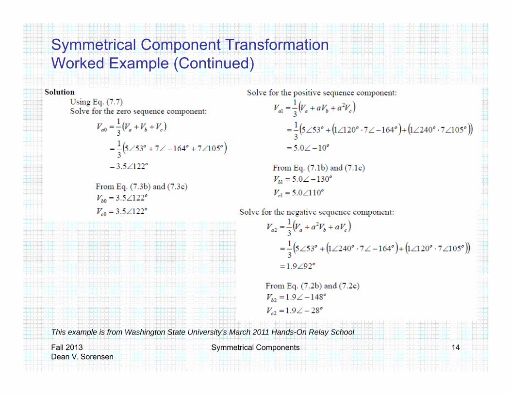
Symmetrical Component Transformation Worked Example (Continued)
Fall 2013Dean V. Sorensen
Symmetrical Components 14
This example is from Washington State University’s March 2011 Hands-On Relay School
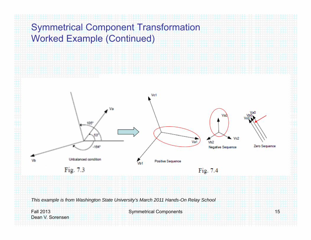
Symmetrical Component Transformation Worked Example (Continued)
Fall 2013Dean V. Sorensen
Symmetrical Components 15
This example is from Washington State University’s March 2011 Hands-On Relay School
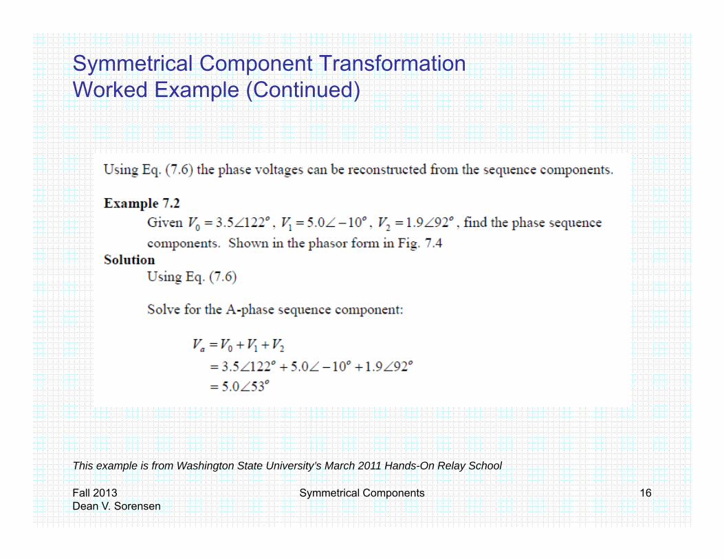
Symmetrical Component Transformation Worked Example (Continued)
Fall 2013Dean V. Sorensen
Symmetrical Components 16
This example is from Washington State University’s March 2011 Hands-On Relay School

Symmetrical Component Transformation Worked Example (Continued)
This example is from Washington State University’s March 2011 Hands-On Relay School
Fall 2013Dean V. Sorensen
Symmetrical Components 17
y

Circuit Element Sequence Representations
Fall 2013Dean V. Sorensen
Symmetrical Components 18

Circuit Element Sequence Representations3-Phase System with Sending and Receiving End Voltages
Fall 2013Dean V. Sorensen
Symmetrical Components 19

Circuit Element Sequence RepresentationsSelf Impedances• The voltage drop equations in matrix form for our system are
AACABAAARAS IZZZVV
St ti ith KVL d th l th lf i d f l A (i th lt d
⋅
=
−
C
B
CCCBCA
BCBBBA
CR
BR
CS
BS
II
ZZZZZZ
VV
VV
• Starting with KVL around the loop, the self impedance of loop A (i.e. the voltage drop in loop A resulting from the current in loop A) is
( ) ( ) AAGAAAGAARAS IXXjIRRVV +++=−
( ) ( )AGAAGAA
ARASAA XXjRR
IVVZ +++=−=
• ZBB and ZCC in the impedance matrix are similarly defined.
Fall 2013Dean V. Sorensen
Symmetrical Components 20
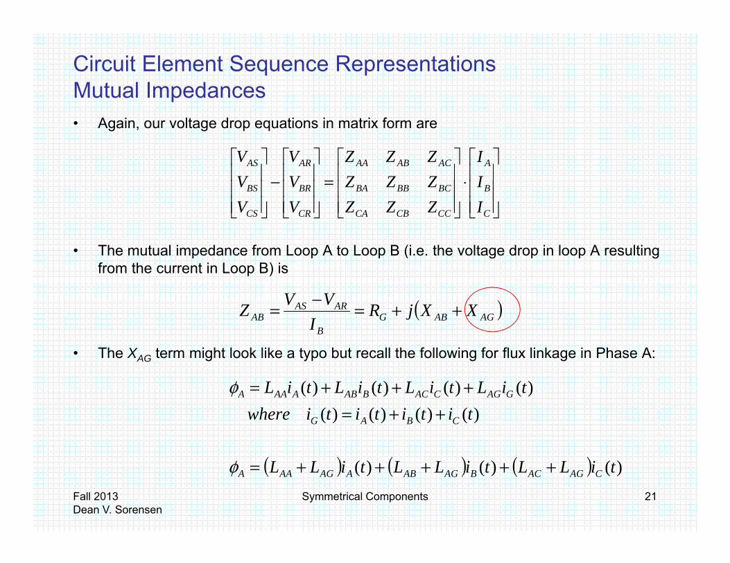
Circuit Element Sequence RepresentationsMutual Impedances• Again, our voltage drop equations in matrix form are
AACABAAARAS IZZZVV
Th t l i d f L A t L B (i th lt d i l A lti
⋅
=
−
C
B
CCCBCA
BCBBBA
CR
BR
CS
BS
II
ZZZZZZ
VV
VV
• The mutual impedance from Loop A to Loop B (i.e. the voltage drop in loop A resulting from the current in Loop B) is
( )AGABGARAS
AB XXjRVVZ ++=−=
• The XAG term might look like a typo but recall the following for flux linkage in Phase A:
( )AGABGB
AB jI
)()()()( tiLtiLtiLtiL +++=φ
( ) ( ) ( )
)()()()()()()()(
titititiwheretiLtiLtiLtiL
CBAG
GAGCACBABAAAA
++=+++=φ
Fall 2013Dean V. Sorensen
Symmetrical Components 21
( ) ( ) ( ) )()()( tiLLtiLLtiLL CAGACBAGABAAGAAA +++++=φ
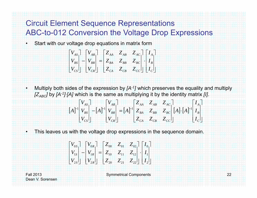
Circuit Element Sequence RepresentationsABC-to-012 Conversion the Voltage Drop Expressions• Start with our voltage drop equations in matrix form
⋅
=
−
II
ZZZZZZ
VV
VV AACABAAARAS
g p p
M lti l b th id f th i b [A 1] hi h th lit d lti l
=
I
IZZZZZZ
VV
VV
C
B
CCCBCA
BCBBBA
CR
BR
CS
BS
• Multiply both sides of the expression by [A-1] which preserves the equality and multiply [ZABC] by [A-1]·[A] which is the same as multiplying it by the identity matrix [I].
[ ] [ ] [ ] [ ] [ ]
⋅
=
−
−−−− 1111 II
AAZZZZZZ
AVV
AVV
AA
CA
ACABAAAR
S
AS
• This leaves us with the voltage drop expressions in the sequence domain.
[ ] [ ] [ ] [ ] [ ]
I
IAAZZZZZZA
VVA
VVA
C
B
CCCBCA
BCBBBA
CR
BR
CS
BS
⋅
=
−
2
1
0
222120
121110
020100
2
1
0
2
1
0
III
ZZZZZZZZZ
VVV
VVV
R
R
R
S
S
S
Fall 2013Dean V. Sorensen
Symmetrical Components 22
222212022 IZZZVV RS
Circuit Element Sequence RepresentationsSequence Independence and Sequence Coupling
002010000 IZZZVV RS
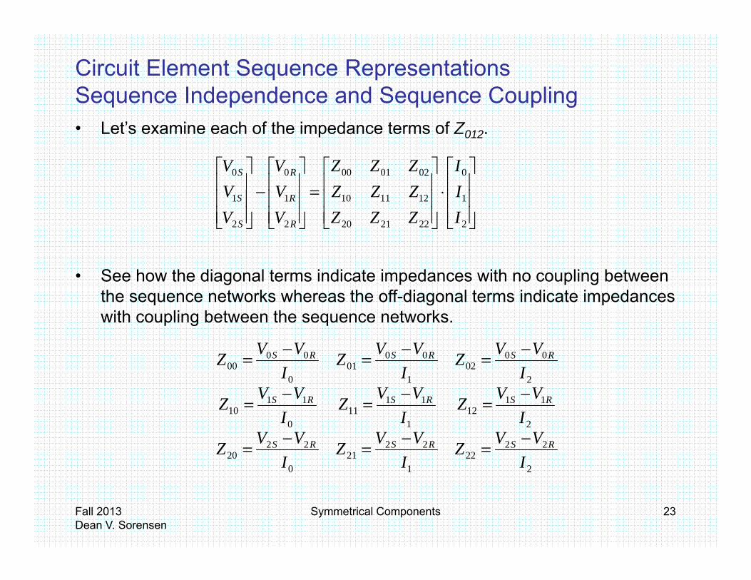
• Let’s examine each of the impedance terms of Z012.
q p q p g
2
1
222120
121110
2
1
2
1
II
ZZZZZZ
VV
VV
R
R
S
S
⋅
=
−
• See how the diagonal terms indicate impedances with no coupling between the sequence networks whereas the off-diagonal terms indicate impedances with coupling between the sequence networks.
111111
2
0002
1
0001
0
0000
VVZVVZVVZ
IVVZ
IVVZ
IVVZ
RSRSRS
RSRSRS
−−−
−=−=−=
2
2222
1
2221
0
2220
2
1112
1
1111
0
1110
IVVZ
IVVZ
IVVZ
IZ
IZ
IZ
RSRSRS
RSRSRS
−=−=−=
===
Fall 2013Dean V. Sorensen
Symmetrical Components 23

Cases of Impedance Matrices with High SymmetryCase 1 – Symmetrical Passive Elementsy• In the case of transmission lines, common assumptions include symmetrically spaced
phase conductors with regular conductor transposition. This yields the following equalities:
ACCBBACABCABM
CCBBAAS
CBAP
XXXXXXXXXXX
RRRR
=========
===
CGBGAGG
CCCC
XXXX ===
• This in turn enables the introduction of new variables representing self and mutual
)( GSGP
CCBBAAS
XXjRRZZZZ
+++====
a ab es ep ese t g se a d utuaimpedances.
)(
)(
ACCBBACABCABM
GSGP
XXjRZZZZZZZ
XXjRR
++=======
+++
Fall 2013Dean V. Sorensen
Symmetrical Components 24
)( GMG XXjR ++=

Cases of Impedance Matrices with High SymmetryCase 1 – Symmetrical Passive Elementsy• Now we substitute ZS for the self impedance and ZM for the mutual impedances in the
ZABC impedance matrix
=
=
SMM
MSM
MMS
CCCBCA
BCBBBA
ACABAA
ABC
ZZZZZZZZZ
ZZZZZZZZZ
Z
• And convert to Z012.
[ ] [ ]
−−
+=⋅
⋅= −
MS
MS
MS
SMM
MSM
MMS
ZZZZ
ZZA
ZZZZZZZZZ
AZ00
00002
1012
• Notice that Z012 contains only diagonal elements (i.e. no coupling between sequence networks) and that Z11 = Z22. The more common form of expression is that Z1 = Z2.
Fall 2013Dean V. Sorensen
Symmetrical Components 25
networks) and that Z11 Z22. The more common form of expression is that Z1 Z2.
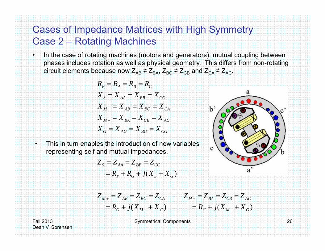
Cases of Impedance Matrices with High SymmetryCase 2 – Rotating Machinesg• In the case of rotating machines (motors and generators), mutual coupling between
phases includes rotation as well as physical geometry. This differs from non-rotating circuit elements because now ZAB ≠ ZBA, ZBC ≠ ZCB and ZCA ≠ ZAC.
CABCABM
CCBBAAS
CBAP
XXXXXXXX
RRRR
======
===
+
CGBGAGG
ACCBBAM
CABCABM
XXXXXXXX
======−
+
Thi i t bl th i t d ti f i bl
)(CCBBAAS
XXjRRZZZZ
+++====
• This in turn enables the introduction of new variables representing self and mutual impedances.
)()(
)(
ACCBBAMCABCABM
GSGP
XXjRZZZZ
XXjRZZZZ
XXjRR
======
+++=
−+
Fall 2013Dean V. Sorensen
Symmetrical Components 26
)()( GMGGMG XXjRXXjR ++=++= −+

Cases of Impedance Matrices with High SymmetryCase 2 – Rotating Machinesg• Now we substitute ZS for the self impedance and ZM for the mutual impedances in the
ZABC impedance matrix
=
=
+
+−
−+
SMM
MSM
MMS
CCCBCA
BCBBBA
ACABAA
ABC
ZZZZZZZZZ
ZZZZZZZZZ
Z
• And convert to Z012.
−+ SMMCCCBCA ZZZZZZ
[ ] [ ]
++++
++=⋅
⋅=
−+
−+
−+
−+
+−
−+−
MMS
MMS
MMS
SMM
MSM
MMS
ZaaZZaZZaZ
ZZZA
ZZZZZZZZZ
AZ2
21012
000000
• Notice that Z012 contains only diagonal elements (i.e. no coupling between sequence networks) and that this time Z11 ≠ Z22 or the more common form of expression is that Z1 ≠ Z2.
Fall 2013Dean V. Sorensen
Symmetrical Components 27
1 2

Fall 2013Dean V. Sorensen
Symmetrical Components 28

Circuit Element Sequence RepresentationsSequence NetworksSequence Networks
• Elements of a power system are represented by their impedances and characteristics in each of sequence networks. For a 3-phase
tpower system:
– Zero sequence - represents impedances of the system to equal(in phase) currents in all three phases(in-phase) currents in all three phases.
– Positive sequence - represents impedances of the system to normal (balanced) currents in all three phasesnormal (balanced) currents in all three phases.
– Negative sequence - represents impedances of the system to currents with reversed phase sequencecurrents with reversed phase sequence.
Fall 2013Dean V. Sorensen
Symmetrical Components 29

Circuit Element Sequence RepresentationsSequence Network IndependenceSeque ce et o depe de ce• Each of the sequence networks is independent of the others.
For a balanced network:• For a balanced network:– Sequence currents flowing in a balanced network produce only like
sequence network voltage drops.• Thus the sequence networks are not connected to each other.q• Unbalanced sources resolve to zero, positive and negative sequence
sources.
• For unbalanced network:• For unbalanced network:– In general, sequence currents can produce all three sequence network
voltage drops. • Thus, we model unbalances by setting up independent sequence networks
f ( fand interconnecting them at the point of the unbalance (i.e. the fault location).
• For these studies we assume the rest of the system and all the sources are balanced (i.e. no sources in the zero and negative sequence networks).
Fall 2013Dean V. Sorensen
Symmetrical Components 30

Circuit Element Sequence RepresentationsSystem Equivalent Sources (i e Non-rotating)
• Short circuit kVA or MVA values are used to express the fault duty of an equivalent source at a point in the power system and can be
System Equivalent Sources (i.e. Non rotating)
an equivalent source at a point in the power system and can be converted to equivalent impedances.
– Sometimes you may get driving point a.k.a. Thevenin impedances from a short circuit program such as CAPE or Aspen Generally they providea short circuit program such as CAPE or Aspen. Generally they provide Z0 and Z1 values and you assume Z2 = Z1.
– Alternatively you may be given fault duties expressed in MVA or kVA based on the dri ing point (i e base s stem) oltage and a ailable fa ltbased on the driving point (i.e. base system) voltage and available fault current. You need both 3 phase (S3ph or MVASC) and SLG (S1ph or MVAGSC) fault duties to calculate sequence impedances (see next slide). With this method assume impedances to be all reactive.
• For hand calculations you can often assume an ideal voltage source, a.k.a. an infinite bus, (i.e. Z0 = Z1 = Z2 = 0).
Fall 2013Dean V. Sorensen
Symmetrical Components 31
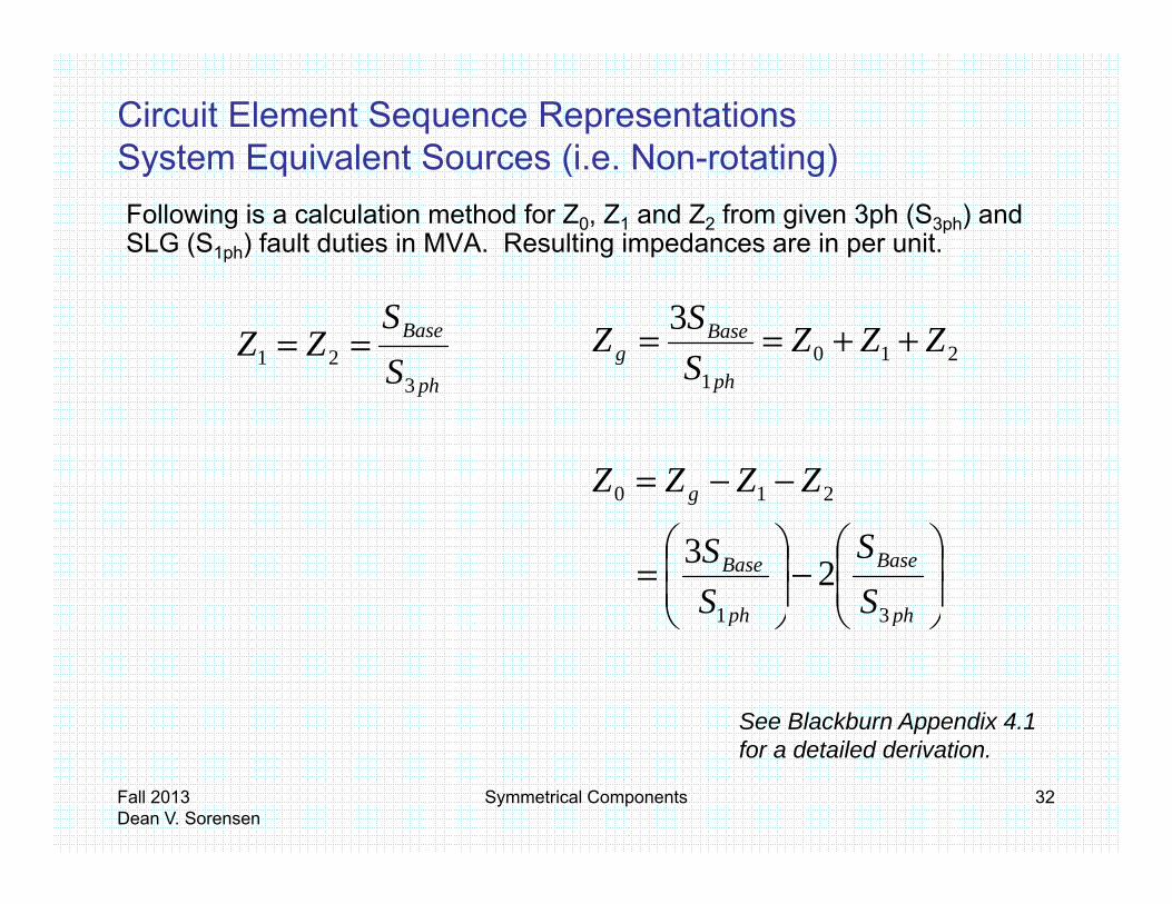
Circuit Element Sequence RepresentationsSystem Equivalent Sources (i.e. Non-rotating)Following is a calculation method for Z0, Z1 and Z2 from given 3ph (S3ph) and SLG (S1ph) fault duties in MVA. Resulting impedances are in per unit.
System Equivalent Sources (i.e. Non rotating)
ph
Base
SS
ZZ3
21 == ++==ph
Baseg ZZZ
SSZ 210
1
3
p
−−= g ZZZZ 210
−
=
ph
Base
ph
Base
SS
SS
31
23
See Blackburn Appendix 4.1
pp
Fall 2013Dean V. Sorensen
Symmetrical Components 32
for a detailed derivation.

Circuit Element Sequence Representations Synchronous Generators
For a sustained fault on the terminals of an unloaded generator, the armature current has a decrement as shown below. This defines
t i dgenerator impedances.
Fall 2013Dean V. Sorensen
Symmetrical Components 33

Circuit Element Sequence RepresentationsSynchronous Generators
• Reactance increases with time after a short circuit because of the demagnetizing effect of the fault current on the air-gap flux For round
Synchronous Generators
demagnetizing effect of the fault current on the air gap flux. For round rotor machines, typical positive sequence impedances are as follows:
0.95 < Xd <1.45 0.12 < Xd’ <0.28 pu on generator base
0.07 < Xd’’ <0.17
N ti i d i ft i t d b ti it t• Negative-sequence impedance is often approximated by equating it to the subtransient reactance.
X2 = Xd’’X2 Xd
Fall 2013Dean V. Sorensen
Symmetrical Components 34

Circuit Element Sequence RepresentationsGenerators – Induction Machines
• Induction machines (motors or generators) are not generally considered sources of fault current for relaying purposes.
Generators Induction Machines
co s de ed sou ces o au t cu e t o e ay g pu poses
• The fault current contribution from an induction machine decays in a few cyclesdecays in a few cycles.
• Induction machine contribution to fault current (subtransient reactance) may be considered when performing maximumreactance) may be considered when performing maximum instantaneous fault current studies for bus and switchgear rating purposes.
Fall 2013Dean V. Sorensen
Symmetrical Components 35

Circuit Element Sequence RepresentationsBalanced 3-Phase Sources
Zero-sequence impedance depends on the manner in which the generator is grounded. Any impedance in the neutral circuit (Zn) is
Balanced 3 Phase Sources
represented as three times this value (3Zn) in the zero-sequence model since 3I0 flows through the neutral.
Z0
3ZnZ1
E
+
Z2
External neutral3Zn1
REF REF REF
POSITIVE NEGATIVE ZERO
External neutral impedance.
For solidly SEQUENCE SEQUENCE SEQUENCE grounded neutral
3Zn= 0.
For ungrounded
Fall 2013Dean V. Sorensen
Symmetrical Components 36
For ungrounded neutral 3Zn = ∞
Circuit Element Sequence RepresentationsLoad Impedances
• Positive and negative sequence impedances of loads are generally l Th h f h b i i
Load Impedances
equal. These are shown on a reference phase basis in sequence networks.
• For synchronous motors particularly those that are designed with• For synchronous motors, particularly those that are designed with salient poles, the negative sequence impedance generally lies between Xd’ and Xd’’.
• Zero sequence impedance of loads depends on the manner in which they are connected and grounded as shown on the following page.
Fall 2013Dean V. Sorensen
Symmetrical Components 37

Circuit Element Sequence RepresentationsZero Sequence Models for Different Load Connections
Z
Z
Z N
Z
N
q
Z
Z
REF
Z3I
Z
Z N
REF
3I0N
Connection Arrangement
Zero Sequence Equivalent Circuit
Z
Z
Z NZn
3I0 Z
3Zn
N
Z
Z
REF
Z0
Fall 2013Dean V. Sorensen
Symmetrical Components 38
Z
REF
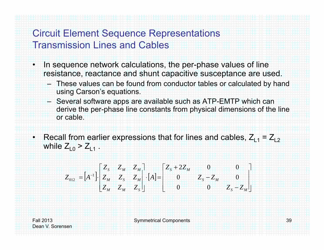
Circuit Element Sequence RepresentationsTransmission Lines and Cables
• In sequence network calculations, the per-phase values of line resistance, reactance and shunt capacitive susceptance are used.
Transmission Lines and Cables
p p– These values can be found from conductor tables or calculated by hand
using Carson’s equations. – Several software apps are available such as ATP-EMTP which can
derive the per phase line constants from physical dimensions of the linederive the per-phase line constants from physical dimensions of the line or cable.
• Recall from earlier expressions that for lines and cables, ZL1 = ZL2p , L1 L2while ZL0 > ZL1 .
[ ]
+
MSMMS ZZZZZ 002
[ ] [ ]
−−=⋅
⋅= −
MS
MS
SMM
MSM
ZZZZA
ZZZZZZAZ
00001
012
Fall 2013Dean V. Sorensen
Symmetrical Components 39

Circuit Element Sequence RepresentationsSample ATP-EMTP Output for OH Transmission Lines
Impedance matrix, in units of [ohms/mile ] for the system of equivalent phase conductors.
p pCalculated impedances are for a typical 345kV transmission line (left-most tower configuration shown below) with two bundled conductors per phase.
Rows and columns proceed in the same order as the sorted input.ZAA
1 2.780137E-011.099286E+00
ZBA ZBB2 2.305740E-01 2.910487E-01
5 180598E 01 1 085324E+005.180598E-01 1.085324E+00ZCA ZCB ZCC
3 2.230820E-01 2.305750E-01 2.780138E-014.412611E-01 5.181495E-01 1.099286E+00
Impedance matrix, in units of [ohms/mile ] for symmetrical components of the equivalent phase conductorRows proceed in the sequence (0, 1, 2), (0, 1, 2), etc.; Columns proceed in the sequence (0, 2, 1), (0, 2, 1), etc.
Z00 0 7.385127E-01
2.079613E+00Z10 Z12
1 2 156088E 02 4 804473E 02
( ) ( )AGAAGAAA XXjRRZ +++=
( )AGABGAB XXjRZ ++=1 -2.156088E-02 -4.804473E-02-4.577000E-03 2.854904E-02
Z20 Z22 Z212 1.471788E-02 5.428174E-02 4.869572E-02-1.642828E-02 6.021421E-01 2.742369E-02
−−
+=
MS
MS
MS
ZZZZ
ZZZ
0000002
012
Fall 2013Dean V. Sorensen
Symmetrical Components 40

Circuit Element Sequence RepresentationsZL0 for Overhead Transmission Lines
• The zero sequence impedance, ZL0, of an overhead line depends on l f t hi h lt i id i ti
ZL0 for Overhead Transmission Lines
several factors which can result in wide variation.
– The use of overhead shield wires and the type of tower grounding and t icounterpoise.
– Ground resistivity.
– Zero-sequence impedance is usually 2 to 3.5 times the positive-sequence impedance.
Fall 2013Dean V. Sorensen
Symmetrical Components 41
Circuit Element Sequence RepresentationsZL0 for Transmission Line Cables
• For cables, the type of sheath or pipe used in the construction is a j f t i th i d
ZL0 for Transmission Line Cables
major factor in the zero-sequence impedance.
• In addition, the placement of the phase conductors relative to each other affects the amount of current flow in the cable sheaths or pipe and thus has a significant impact on the zero-sequence impedance.
Fall 2013Dean V. Sorensen
Symmetrical Components 42

Circuit Element Sequence RepresentationsPipe-type Cables – R0 and X0Pipe type Cables R0 and X0
• Things expand when they heat up so R0 and X0 in pipe type cables vary with current loading.
• Most fault studies will choose a current level at which to study the cable, usually a level corresponding with the available fault current.
35
40
6
7
8
, y p g
R0/
R1
15
20
25
30
X0/X
13
4
5
6
0
5
10
10 100 1000 10000 1000001
2
3
10 100 1000 10000 100000
Fall 2013Dean V. Sorensen
Symmetrical Components 43
Total Pipe Current - Am peres Total Pipe Current - Am peres
Circuit Element Sequence RepresentationsTransformers – Positive and Negative Sequence
• The positive and negative-sequence impedances of a transformer are equal and are the leakage impedance of the transformer
Transformers Positive and Negative Sequence
are equal and are the leakage impedance of the transformer.
• Positive-sequence voltages and currents are shifted ± 30° when passing through a Delta - Wye transformer bank The sign of thepassing through a Delta - Wye transformer bank. The sign of the phase shift is determined by the transformer connections.
• Negative sequence voltages and currents are correspondinglyNegative sequence voltages and currents are correspondingly shifted by the opposite phase shift.
• No phase shift occurs in the zero sequence network.o p ase s t occu s t e e o seque ce et o
Fall 2013Dean V. Sorensen
Symmetrical Components 44

Circuit Element Sequence RepresentationsTransformers – Zero Sequence
• Where a three-phase transformer bank is arranged without interlinking magnetic flux (that is a three-phase shell type or three single phase units) and provided there
Transformers Zero Sequence
shell type, or three single-phase units) and provided there is a path for zero sequence currents, the zero sequence impedance is equal to the positive sequence impedance.
• In the case of three-phase core type units, the zero p yp ,sequence fluxes produced by zero sequence currents can find a high reluctance path, the effect being to reduce the zero sequence impedance to about 90% of the positive sequence impedance.
Shell-type
• However, in hand calculations, it is usual to ignore this variation and consider the positive and zero sequence impedances to be equal. It is common when using software to perform fault calculations to enter a value of zero sequence impedance in accordance with the abovezero-sequence impedance in accordance with the above guidelines, if the manufacturer is unable to provide a value.
Core-typeSource: Areva Network Protection and Automation Guide Chapter 5 page 57
Fall 2013Dean V. Sorensen
Symmetrical Components 45
Source: Areva Network Protection and Automation Guide, Chapter 5, page 57.
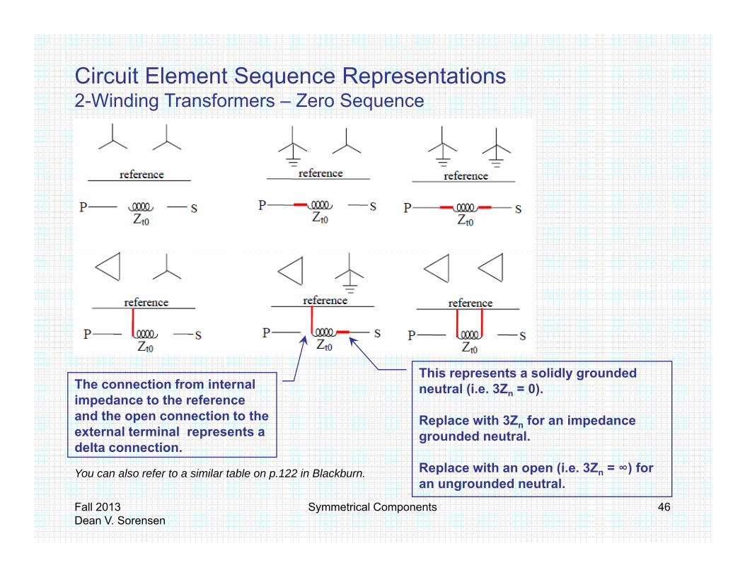
Circuit Element Sequence Representations2-Winding Transformers – Zero Sequence2 Winding Transformers Zero Sequence
This represents a solidly grounded neutral (i.e. 3Zn = 0).The connection from internal
i d t th f
f
Replace with 3Zn for an impedance grounded neutral.
Replace with an open (i e 3Z = ∞) for
impedance to the reference and the open connection to the external terminal represents a delta connection.
Fall 2013Dean V. Sorensen
Symmetrical Components 46
You can also refer to a similar table on p.122 in Blackburn. Replace with an open (i.e. 3Zn = ∞) for an ungrounded neutral.
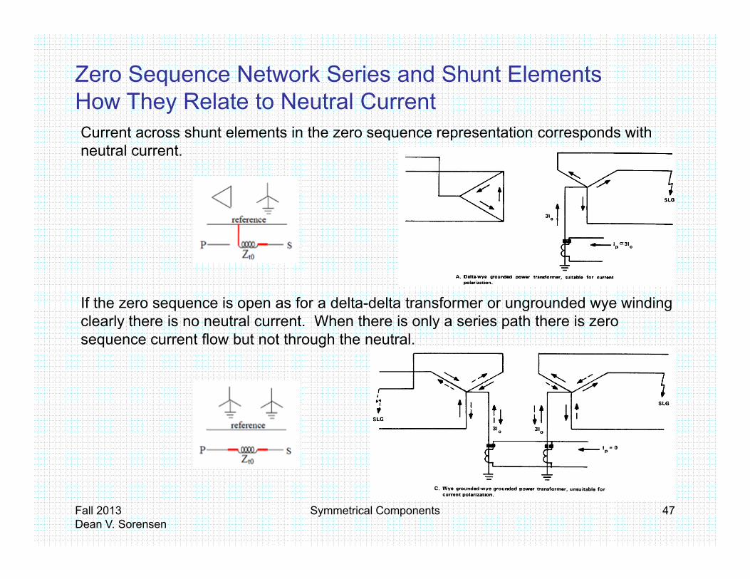
Zero Sequence Network Series and Shunt ElementsHow They Relate to Neutral CurrentHow They Relate to Neutral Current Current across shunt elements in the zero sequence representation corresponds with neutral current.
If the zero sequence is open as for a delta-delta transformer or ungrounded wye winding clearly there is no neutral current. When there is only a series path there is zero c ea y t e e s o eut a cu e t e t e e s o y a se es pat t e e s e osequence current flow but not through the neutral.
Fall 2013Dean V. Sorensen
Symmetrical Components 47
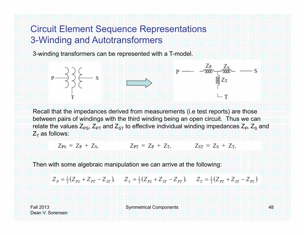
Circuit Element Sequence Representations3-Winding and Autotransformersg3-winding transformers can be represented with a T-model.
Recall that the impedances derived from measurements (i.e test reports) are those between pairs of windings with the third winding being an open circuit. Thus we can relate the values ZPS, ZPT and ZST to effective individual winding impedances ZP, ZS and Z as follo sZT as follows:
fThen with some algebraic manipulation we can arrive at the following:
Fall 2013Dean V. Sorensen
Symmetrical Components 48

Circuit Element Sequence Representations3-Winding and Autotransformers – Positive and Negative Sequenceg g q
The positive and negative sequence representations are the same and simply include solid connections from the internal impedances ZP, ZS and ZT to the external terminals P, S and T as shown below right.
Ref.
Fall 2013Dean V. Sorensen
Symmetrical Components 49

Circuit Element Sequence Representations3-Winding and Autotransformers – Zero Sequenceg q
Zero sequence representations use the same internal connection rules for each winding configuration as seen in the 2-winding example.
Note for N-Winding Transformers:
You can also refer to a similar table on p.124 in Blackburn.
Representation of transformers with more than 3 windings (i.e. N-winding transformers) follow the same process and connection rules as 3-winding
Fall 2013Dean V. Sorensen
Symmetrical Components 50
and connection rules as 3 winding transformers.

Fall 2013Dean V. Sorensen
Symmetrical Components 51

Fault Analysis Using Symmetrical ComponentsExample System (Fault at Bus C)
Fall 2013Dean V. Sorensen
Symmetrical Components 52

Fault Analysis Using Symmetrical Components3-Phase (3PH) Fault( )
At the fault point Va = Vb = Vc = 0 and Ia = Ib = Ic
Since Va = Vb = Vc = 0
a
b
From the definitions: V0 = V1 = V2 = 0
Since Ia = Ib = Ic From the definitions: I0 = 0 and I2 = 0
As expected these relationships
c
As expected, these relationships suggest only the positive sequence network to be connected at the fault point.
REFERENCE EQUATIONS
( )cba VVVV ++=0 31 ( )cba IIII ++=0 3
1
210 VVVV ++= 210 IIIIa ++=( )
( )cba
cba
aVVaVV
VaaVVV
++=
++=
22
21
3131 ( )
( )cba
cba
aIIaII
IaaIII
++=
++=
22
21
3131
22
10
212
0
210
VaaVVVaVVaVV
VVVV
c
b
a
++=
++=
++
22
10
212
0
210
IaaIIIaIIaII
c
b
a
++=
++=
Fall 2013Dean V. Sorensen
Symmetrical Components 53

Fault Analysis Using Symmetrical Components3-Phase (3PH) Fault
0IIIVVV cba
=====a
b III cba ==c
1 ZVIa =
1Z
Fall 2013Dean V. Sorensen
Symmetrical Components 54

Fault Analysis Using Symmetrical Components3-Phase (3PH) Fault( )
Z1I1
IIIV1V
I
POS0=====
VVVIII
cba
cba
Z2
V2
I2
NEG00
20
1
==≈
VVV
Z0I0
020
0
== II
Notice there is a extra
V0ZERO
component of V1 and I1 present because of load current and source impedance.
Fall 2013Dean V. Sorensen
Symmetrical Components 55
The above fault record is from Washington State University’s March 2011 Hands-On Relay School

Fault Analysis Using Symmetrical ComponentsSingle-Line-to-Ground (SLG) Faultg ( )
a
b
At the fault point Va = 0 and Ib = Ic = 0
cSince Va = 0 V0 + V1 + V2 = 0
Since Ib = Ic = 0 I0 + a2I1 + aI2 = 0 andI0 + aI1 + a2I2 = 0 These relationships suggest that
all three sequence networks areWhich simplifies to I0 = I1 = I2
all three sequence networks are connected in series at the fault point.
REFERENCE EQUATIONS
( )cba VVVV ++=0 31 ( )cba IIII ++=0 3
1IIII
( )
( )cba
cba
aVVaVV
VaaVVV
++=
++=
22
21
31313
( )
( )cba
cba
aIIaII
IaaIII
++=
++=
22
21
31313
22
10
212
0
210
VaaVVVaVVaVV
VVVV
c
b
a
++=
++=
++=
22
10
212
0
210
IaaIIIaIIaII
IIII
c
b
a
++=
++=
++=
Fall 2013Dean V. Sorensen
Symmetrical Components 56
3

Fault Analysis Using Symmetrical ComponentsSingle-Line-to-Ground (SLG) Fault
00II
V
b
a
===
0II cb
021021 ZZZ
VIII aaa ++===
0210021
33ZZZ
VIIIII aaaaa ++==++=
Fall 2013Dean V. Sorensen
Symmetrical Components 57

Fault Analysis Using Symmetrical ComponentsSingle-Line-to-Ground (SLG) Fault
I1Z1
00II
V
cb
a
===
Z1
V1V
POS
0VVV
cb
Z2
V
I2
NEG
210
210 0IIIVVV
≈≈≈++
Notice there is a extra
V2
Z0I0
Notice there is a extra component of V1 and I1 present because of load current and source impedance.
V0
ZERO
Fall 2013Dean V. Sorensen
Symmetrical Components 58
The above fault record is from Washington State University’s March 2011 Hands-On Relay School

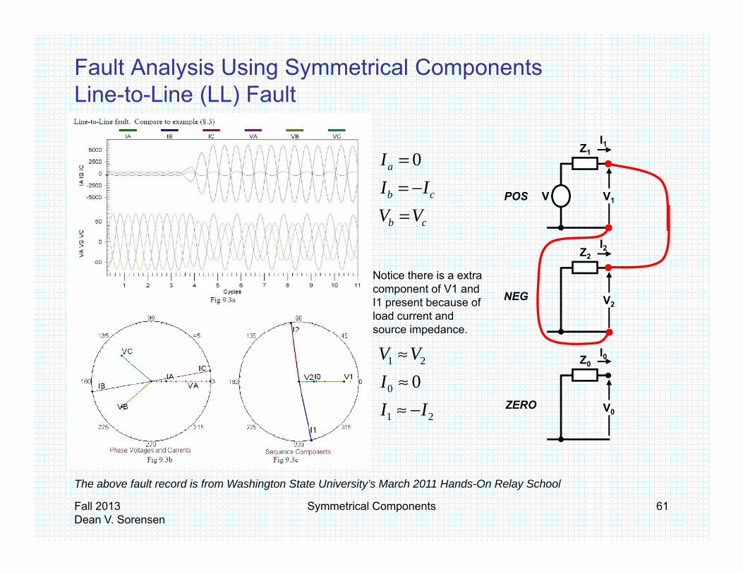
Fault Analysis Using Symmetrical ComponentsLine-to-Line (LL) Fault( )
At the fault point Ia = 0 and Ib = -Ic and Vb = Vc
Since V V V + a2V + aV V + aV + a2V
a
bSince Vb = Vc V0 + a2V1 + aV2 = V0 + aV1 + a2V2Which simplifies to V1 = V2
Since Ib = -Ic I0 + a2I1 + aI2 = -(I0 + aI1 + a2I2)Which simplifies to I1 = -I2
b
c
p 1 2
Since Ia = 0 I0 + I1 + I2 = 0 where I1 = -I2Which simplifies to I0 = 0
These relationships suggest the positive and negative sequence networks are connected in parallel at the fault point.
REFERENCE EQUATIONS
( )cba VVVV ++=0 31 ( )cba IIII ++=0 3
1IIII
( )
( )cba
cba
aVVaVV
VaaVVV
++=
++=
22
21
31313
( )
( )cba
cba
aIIaII
IaaIII
++=
++=
22
21
31313
22
10
212
0
210
VaaVVVaVVaVV
VVVV
c
b
a
++=
++=
++=
22
10
212
0
210
IaaIIIaIIaII
IIII
c
b
a
++=
++=
++=
Fall 2013Dean V. Sorensen
Symmetrical Components 59
3

Fault Analysis Using Symmetrical ComponentsLine-to-Line (LL) Fault
0
cb
a
III
−==
cb VV =
2121 aa ZZ
VII+
=−=
21 aa VV =
Fall 2013Dean V. Sorensen
Symmetrical Components 60
Fault Analysis Using Symmetrical ComponentsLine-to-Line (LL) Fault( )
0Ia =Z1
I1
VVII
cb
cb
=−= V1V
ZI2
POS
Z2
V2NEG
Notice there is a extra component of V1 and I1 present because of load current and
0
21
0IVV
≈≈ Z0
I0
source impedance.
21 II −≈ V0ZERO
Fall 2013Dean V. Sorensen
Symmetrical Components 61
The above fault record is from Washington State University’s March 2011 Hands-On Relay School
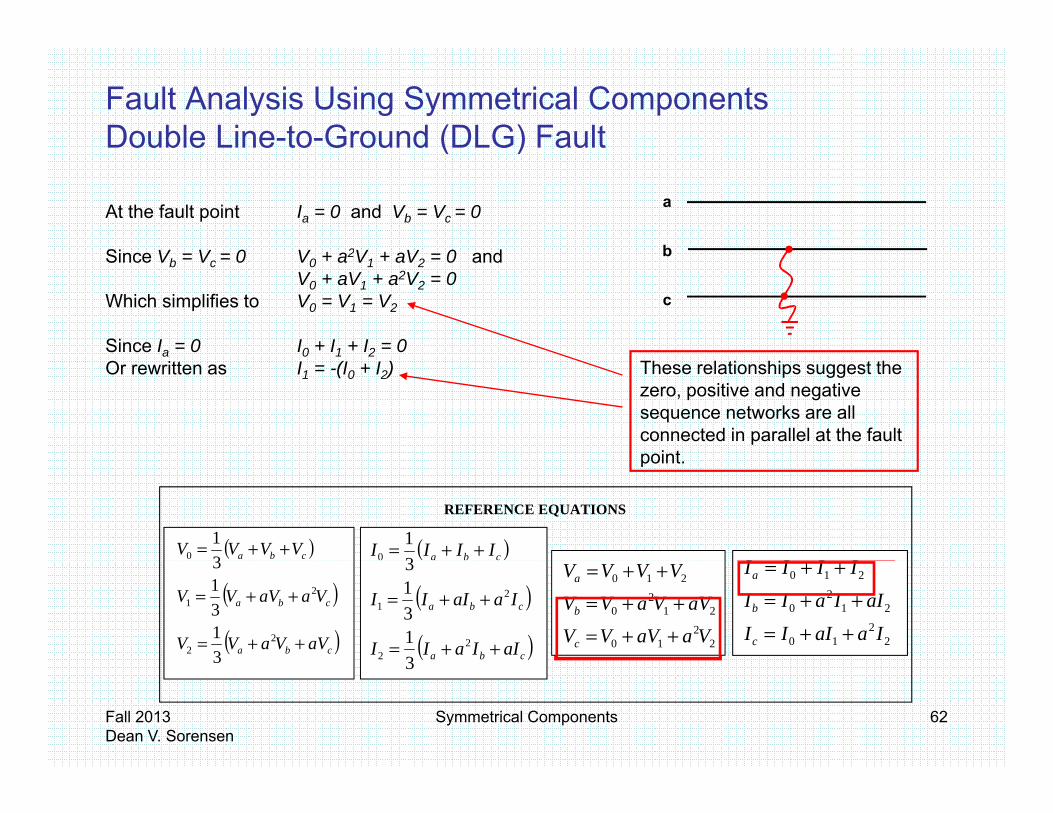
Fault Analysis Using Symmetrical ComponentsDouble Line-to-Ground (DLG) Fault( )
At the fault point Ia = 0 and Vb = Vc = 0
Since V V 0 V + a2V + aV 0 and
a
bSince Vb = Vc = 0 V0 + a2V1 + aV2 = 0 andV0 + aV1 + a2V2 = 0
Which simplifies to V0 = V1 = V2
Since Ia = 0 I0 + I1 + I2 = 0
b
c
a 0 1 2Or rewritten as I1 = -(I0 + I2) These relationships suggest the
zero, positive and negative sequence networks are all connected in parallel at the fault pointpoint.
REFERENCE EQUATIONS
( )cba VVVV ++=0 31 ( )cba IIII ++=0 3
1IIII
( )
( )cba
cba
aVVaVV
VaaVVV
++=
++=
22
21
31313
( )
( )cba
cba
aIIaII
IaaIII
++=
++=
22
21
31313
22
10
212
0
210
VaaVVVaVVaVV
VVVV
c
b
a
++=
++=
++=
22
10
212
0
210
IaaIIIaIIaII
IIII
c
b
a
++=
++=
++=
Fall 2013Dean V. Sorensen
Symmetrical Components 62
3
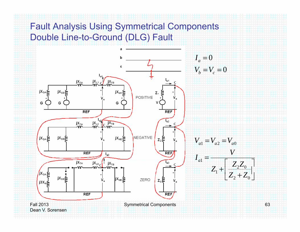
Fault Analysis Using Symmetrical ComponentsDouble Line-to-Ground (DLG) Fault
===
00VV
I
cb
a
0
b
a
III
−==
VV cb
cb
cb
VVII
==
21
2121
aa
aa
VVZZ
VII
=+
=−=
=
==
1
021
VI
VVV
a
aaa
+
+02
021
1
ZZZZZ
a
Fall 2013Dean V. Sorensen
Symmetrical Components 63

Fault Analysis Using Symmetrical ComponentsDouble Line-to-Ground (DLG) Fault
Z1I1
V1V
I
POS0
0VV
I
cb
a
===
Z2
V2
I2
NEG210 VVV ≈≈
Z0I0
( )201
210
IIIVVV+−≈
Notice there is a extra
V0ZERO
component of V1 and I1 present because of load current and source impedance.
Fall 2013Dean V. Sorensen
Symmetrical Components 64
The above fault record is from Washington State University’s March 2011 Hands-On Relay School

Fault Analysis Using Symmetrical ComponentsPhase Shifting Across Delta-Wye TransformersPhase Shifting Across Delta Wye Transformers For this example HV leads LV by 30°. Let the system voltage ratio (N) equal 1. Consequently, the turns ratio (n) must be 1/√3. We know that( ) √
Because the sequence networks are independent, we l th i di id ll ddi th lt bcan apply them individually adding the results by
superposition.
Starting with positive sequence values we get the following for voltage and current.following for voltage and current.
Fall 2013Dean V. Sorensen
Symmetrical Components 65
Pictures and equations are from Appendix 4.3 in Blackburn.
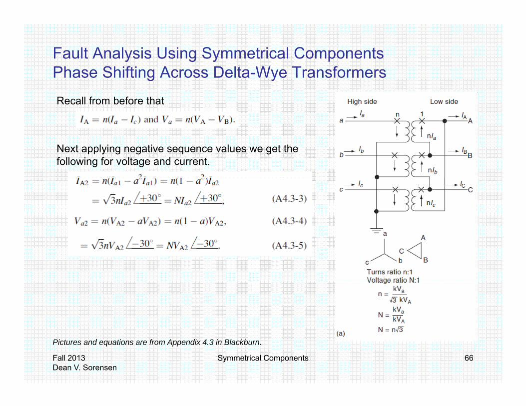
Fault Analysis Using Symmetrical ComponentsPhase Shifting Across Delta-Wye TransformersPhase Shifting Across Delta Wye Transformers
Recall from before that
Next applying negative sequence values we get the following for voltage and current.
Fall 2013Dean V. Sorensen
Symmetrical Components 66
Pictures and equations are from Appendix 4.3 in Blackburn.

Fault Analysis Using Symmetrical ComponentsPhase Shifting Across Delta-Wye TransformersPhase Shifting Across Delta Wye Transformers
• Blackburn Appendix 4.3 provides a second transformer, Example (b), which has a high side delta, low side wye with the HV side similarly leading the low side by 30°.
• The process for determining the positive and negative sequence shift angles is the same as Example (a) as are the actual shift angles.
Fall 2013Dean V. Sorensen
Symmetrical Components 67

Fault Analysis Using Symmetrical ComponentsExample System (Fault at Bus C)
• After interconnecting the sequence networks to model the particular fault type and solving the network to determine the fault current, you likely
t t d t i th i t l lwant to determine other internal values for particular elements – say the current through Generator GB and the voltage behind its reactance.
• You simply determine the current through GB in each network (IGB0, IGB1and IGB2) as well as the 3 voltages across GB (VGB0, VGB1 and VGB2). Recall thatRecall that
• IGBA = IGB0 + IGB1 + IGB2, and• VGBA = VGB0 + VGB1 + VGB2.
• You similarly determine VGBB and VGBC.
Fall 2013Dean V. Sorensen
Symmetrical Components 68

Questions?
Fall 2013Dean V. Sorensen
Symmetrical Components 6969