ieee recommended practice for software design descriptions...
TRANSCRIPT

IEEE Std 1016-1998
(Revision ofIEEE Std 1016-1987)
IEEE Recommended Practice for Software Design Descriptions
Sponsor
Software Engineering Standards Committeeof theIEEE Computer Society
Approved 23 September 1998
IEEE-SA Standards Board
Abstract:
The necessary information content and recommendations for an organization for SoftwareDesign Descriptions (SDDs) are described. An SDD is a representation of a software system that is used asa medium for communicating software design information. This recommended practice is applicable topaper documents, automated databases, design description languages, or other means of description.
Keywords:
software design, software design description, software life cycle process
The Institute of Electrical and Electronics Engineers, Inc.345 East 47th Street, New York, NY 10017-2394, USA
Copyright © 1998 by the Institute of Electrical and Electronics Engineers, Inc.All rights reserved. Published 4 December 1998. Printed in the United States of America.
Print:
ISBN 0-7381-1455-3 SH94688
PDF:
ISBN 0-7381-1456-1 SS94688
No part of this publication may be reproduced in any form, in an electronic retrieval system or otherwise, without the prior writtenpermission of the publisher.
IEEE Standards
documents are developed within the IEEE Societies and the Standards Coordinating Committees ofthe IEEE Standards Association (IEEE-SA) Standards Board. Members of the committees serve voluntarily andwithout compensation. They are not necessarily members of the Institute. The standards developed within IEEErepresent a consensus of the broad expertise on the subject within the Institute as well as those activities outside ofIEEE that have expressed an interest in participating in the development of the standard.
Use of an IEEE Standard is wholly voluntary. The existence of an IEEE Standard does not imply that there are no otherways to produce, test, measure, purchase, market, or provide other goods and services related to the scope of the IEEEStandard. Furthermore, the viewpoint expressed at the time a standard is approved and issued is subject to changebrought about through developments in the state of the art and comments received from users of the standard. EveryIEEE Standard is subjected to review at least every five years for revision or reaffirmation. When a document is morethan five years old and has not been reaffirmed, it is reasonable to conclude that its contents, although still of somevalue, do not wholly reflect the present state of the art. Users are cautioned to check to determine that they have thelatest edition of any IEEE Standard.
Comments for revision of IEEE Standards are welcome from any interested party, regardless of membership affiliationwith IEEE. Suggestions for changes in documents should be in the form of a proposed change of text, together withappropriate supporting comments.
Interpretations: Occasionally questions may arise regarding the meaning of portions of standards as they relate tospecific applications. When the need for interpretations is brought to the attention of IEEE, the Institute will initiateaction to prepare appropriate responses. Since IEEE Standards represent a consensus of all concerned interests, it isimportant to ensure that any interpretation has also received the concurrence of a balance of interests. For this reason,IEEE and the members of its societies and Standards Coordinating Committees are not able to provide an instantresponse to interpretation requests except in those cases where the matter has previously received formalconsideration.
Comments on standards and requests for interpretations should be addressed to:
Secretary, IEEE-SA Standards Board445 Hoes LaneP.O. Box 1331Piscataway, NJ 08855-1331USA
Authorization to photocopy portions of any individual standard for internal or personal use is granted by the Instituteof Electrical and Electronics Engineers, Inc., provided that the appropriate fee is paid to Copyright Clearance Center.To arrange for payment of licensing fee, please contact Copyright Clearance Center, Customer Service, 222 RosewoodDrive, Danvers, MA 01923 USA; (978) 750-8400. Permission to photocopy portions of any individual standard foreducational classroom use can also be obtained through the Copyright Clearance Center.
Note: Attention is called to the possibility that implementation of this standard may require use of subject mattercovered by patent rights. By publication of this standard, no position is taken with respect to the existence orvalidity of any patent rights in connection therewith. The IEEE shall not be responsible for identifying patents forwhich a license may be required by an IEEE standard or for conducting inquiries into the legal validity or scope ofthose patents that are brought to its attention.

Copyright © 1998 IEEE. All rights reserved.
iii
Introduction
(This introduction is not a part of IEEE Std 1016-1998, IEEE Recommended Practice for Software Design Descriptions.)
Purpose
This recommended practice specifies the necessary information content and recommends an organization for SoftwareDesign Descriptions (SDDs). This document does not explicitly support, nor is it limited to, any particular softwaredesign methodology or descriptive technology. It will guide the production of anything from paper design documentsto an automated database of design information. For an organization in the process of developing a design descriptionstandard, use of this document will help the new standard meet the needs of all of its users. For an organization with amature design description standard, it should prove useful in evaluating and modifying that standard in light of theinformational and organizational needs of the design description user community.
This practice can be applied to commercial, scientific, and military software. Applicability is not restricted by size,complexity, or criticality of the software. This practice considers both the software and its system operationalenvironment. It can be used where software is the system or where software is part of a larger system that ischaracterized by hardware and software components and their interfaces.
Overview
This document consists of six clauses. Clause 1 defines the scope of the recommended practice and Clause 2references other standards that should be followed when applying this practice. Clause 3 provides definitions of termswithin the context of the practice. Clause 4 places the SDD into the framework of the software development life cycle.Clause 5 describes the minimum information that shall be included in an SDD and Clause 6 gives a recommendedorganization for SDDs. Annex A shows a sample table of contents for an SDD. Annex B provides guidelines for usingthis standard to meet the requirments of IEEE/EIA 12207.1-1997, IEEE/EIA Guide for Information Technology—Software life cycle processes—Life cycle data.
Audience
This document is intended for those in technical and managerial positions who prepare and use SDDs. It will guide adesigner in the selection, organization, and presentation of design information. It will help standards developers ensurethat a design description is complete, concise, and well organized.
SDDs play a pivotal role in the development and maintenance of software systems. During its lifetime, a given designdescription is used by project managers, quality assurance staff, configuration managers, software designers,programmers, testers, and maintainers. Each of these users has unique needs, both in terms of required designinformation and optimal organization of that information. Hence, a design description must contain all the designinformation needed by those users.
Terminology
This recommended practice follows the
IEEE Standards Style Manual
. In particular, the word
shall
and the imperativeform identify mandatory material within the recommended practice. The words
should
,
might
, and
may
identifyadvisory material.
Limitations
This standard assumes a functional decomposition approach to design understanding. This may limit its utility withobject-oriented approaches.

iv
Copyright © 1998 IEEE. All rights reserved.
History
The project authorization request (PAR) for development of this recommended practice was approved by the IEEEStandards Board on 22 September 1983. Modification of the authorization request to change the title and scope wasapproved on 13 March 1986. A series of 10 meetings were held within the United States and internationally betweenMarch 1983 and March 1986. These meetings produced the draft submitted for balloting in April 1986. The firstedition of this recommended practice was approved by the IEEE Standards Board on 12 March 1987 and reaffirmed on2 December 1993. The PAR for this revision, which added a new Annex B, was approved by the IEEE Standards Boardon 16 September 1997.
Suggestions for the improvement of this practice will be welcome. They should be sent to
Secretary IEEE-SA Standards BoardInstitute of Electrical and Electronics Engineers, Inc.445 Hoes LaneP.O. Box 1331Piscataway, NJ 08855-1331
Original contributors
This document was originally developed by the Software Design Description Working Group of the SoftwareEngineering Standards Subcommittee of the IEEE Computer Society. The Software Design Description WorkingGroup Steering Committee had the following members:
H. Jack Barnard
, Chair
James A. Darling
, Vice Chair
Robert F. Metz
, Secretary
Chris BeallPatricia CoxLeo Endres
H. Gregory FrankManoochehr GhiassiDaniel E. Klingler
John McArdleArthur L. PriceBasil Sherlund
The Software Design Description Working Group had the following members:
Frank AckermanJim AndersonSandro BolognaFletcher BuckleyLori J. CallWan P. ChiangFrançois CoallierCliff CockerhamPatricia W. DaggettJim DeLeoCammie DonaldsonEuiar DragstedtLaurence E. FishtahlerDavid Gelperin
Yair GershkovitchTom GilbShirley A. Gloss-SolerLarry J. HardouinFredrick HoDavid M. HomeWilliam S. JunkLaurel KaledaTom KuriharaJim LemmonF. C. LimOyvind LorentzenBert MartinLindsay McDermidGlen Meldrum
Walter Merenda Randy PetersonRobert PostonIan C. PyleAnn S. PingHans SchaeferDavid SchultzDavid SiefertPeter SmithRichard H. ThayerT. H. TseDavid WeissCharles J. WertzG. Robert Zambs
Copyright © 1998 IEEE. All rights reserved.
v
The following persons were on the balloting committee of the 1998 revision of the recommended practice:
Syed AliTheodore K. AtchinsonMikhail AugustonRobert E. BarryH. Ronald BerlackRichard E. BiehlSandro BolognaJuris BorzovsKathleen L. BriggsM. Scott BuckMichael CaldwellJames E. CardowEnrico A. CarraraLawrence CatchpoleKeith ChanAntonio M. CicuTheo ClarkeSylvain ClermontRosemary ColemanVirgil Lee CooperW. W. Geoff CozensPaul R. CrollPatricia W. DaggettGregory T. DaichTaz DaughtreyBostjan K. DergancPerry R. DeWeeseJames DoEvelyn S. DowCarl Einar DragstedtCharles DrozSherman EaglesLeo EganRichard L. EvansRichard E. FairleyJohn W. FendrichJay ForsterRichard C. FriesRoger U. FujiiAdel N. GhannamMarilyn Ginsberg-FinnerJohn Garth GlynnJulio Gonzalez-Sanz
L. M. GuntherDavid A. GustafsonJon D. HagarJohn HarauzHerbert HechtWilliam HefleyManfred HeinMark HeinrichDebra HerrmannUmesh P. HiriyannaiahJohn W. HorchPeter L. HungGeorge JackelenFrank V. JorgensenVladan V. JovanovicWilliam S. JunkRon S. KenettJudith S. KernerRobert J. KierzykShaye KoenigThomas M. KuriharaJohn B. LaneJ. Dennis LawrenceRandal LeavittFang Ching LimWilliam M. LivelyDieter LookJohn LordStan MageeDavid MaiborHarold MainsRobert A. MartinTomoo MatsubaraMike McAndrewPatrick D. McCraySue McGrathJacques MeekelJames Bret MichaelAlan MillerCelia H. ModellJames W. MoorePavol Navrat
Myrna L. OlsonIndradeb P. PalAlex PolackPeter T. PoonLawrence S. PrzybylskiKenneth R. PtackAnn E. ReedyAnnette D. ReillyDennis RillingAndrew P. SageHelmut SandmayrStephen R. SchachNorman SchneidewindDavid J. SchultzLisa A. SelmonRobert W. ShillatoDavid M. SiefertCarl A. SingerNancy M. SmithLuca SpotornoJulia StesneyFred J. StraussSandra SwearingenToru TakeshitaRichard H. ThayerBooker ThomasPatricia TrellueTheodore J. UrbanowiczGlenn D. VenablesUdo VogesRonald L. WadeDavid D. WaldenDelores WallaceWilliam M. WalshJohn W. WalzCamille S. White-PartainScott A. WhitmireP. A. WolfgangPaul R. WorkZhou Zhi YingJanusz ZalewskiGeraldine ZimmermanPeter F. Zoll

vi
Copyright © 1998 IEEE. All rights reserved.
The final conditions for approval of this standard were met on 23 September 1998. This standard was conditionallyapproved by the IEEE Standards Board on 16 September 1998, with the following membership:
Richard J. Holleman
, Chair
Donald N. Heirman
, Vice Chair
Judith Gorman
, Secretary
Satish K. AggarwalClyde R. CampJames T. CarloGary R. EngmannHarold E. EpsteinJay Forster*Thomas F. GarrityRuben D. GarzonJames H. Gurney
Jim D. IsaakLowell G. JohnsonRobert KennellyE. G. “Al” KienerJoseph L. Koepfinger*Stephen R. LambertJim LogothetisDonald C. LoughryL. Bruce McClung
Louis-François PauRonald C. PetersenGerald H. PetersonJohn B. PoseyGary S. RobinsonHans E. WeinrichDonald W. Zipse
*Member Emeritus
Kristin Dittmann
IEEE Standards Project Editor

Copyright © 1998 IEEE. All rights reserved.
vii
Contents
1. Scope...................................................................................................................................................................1
2. References ...........................................................................................................................................................1
3. Definitions...........................................................................................................................................................2
4. Considerations for producing an SDD ................................................................................................................2
4.1 Software life cycle ..................................................................................................................................... 24.2 SDD within the life cycle........................................................................................................................... 24.3 Purpose of an SDD..................................................................................................................................... 2
5. Design description information content ..............................................................................................................3
5.1 Introduction ................................................................................................................................................ 35.2 Design entities............................................................................................................................................ 35.3 Design entity attributes .............................................................................................................................. 3
6. Design description organization..........................................................................................................................5
6.1 Introduction ................................................................................................................................................ 56.2 Design views .............................................................................................................................................. 6
Annex A (Informative) Sample table of contents for an SDD.....................................................................................10
Annex B (Informative) Guidelines for compliance with IEEE/EIA 12207.1-1997.....................................................11

Copyright © 1998 IEEE. All rights reserved.
1
IEEE Recommended Practice for Software Design Descriptions
1. Scope
This is a recommended practice for describing software designs. It specifies the necessary information content, andrecommended organization for a Software Design Description (SDD). An SDD is a representation of a softwaresystem that is used as a medium for communicating software design information.
The practice may be applied to commercial, scientific, or military software that runs on any digital computer.Applicability is not restricted by the size, complexity, or criticality of the software.
This practice is not limited to specific methodologies for design, configuration management, or quality assurance. It isassumed that the quality design information and changes to the design of description will be managed by other projectactivities. Finally, this document does not support nor is it limited to any particular descriptive technique. It may beapplied to paper documents, automated databases, design description languages, or other means of description.
2. References
This standard shall be used in conjunction with the following publications:
IEEE Std 610.12-1990, IEEE Standard Glossary of Software Engineering Terminology.
1
IEEE Std 730-1998, IEEE Standard for Software Quality Assurance Plans.
IEEE Std 828-1998, IEEE Standard for Software Configuration Management Plans.
IEEE Std 830-1998, IEEE Recommended Practice for Software Requirements Specifications.
Freeman, P. and A. I. Wasserman,
Tutorial on Software Design Techniques.
4th Edition, IEEE Computer Society Press,Annotated Bibliography, pp. 715–718, 1983.
1
IEEE publications are available from the Institute of Electrical and Electronics Engineers, 445 Hoes Lane, P.O. Box 1331, Piscataway, NJ 08855-1331, USA (http://standards.ieee.org/).

2
Copyright © 1998 IEEE. All rights reserved.
IEEE Std 1016-1998 IEEE RECOMMENDED PRACTICE FOR
3. Definitions
The definitions listed here establish meaning in the context of this recommended practice. Definitions of other termsused in this document can be found in IEEE Std 610.12-1990
2
.
3.1 design entity:
An element (component) of a design that is structurally and functionally distinct from otherelements and that is separately named and referenced.
3.2 design view:
A subset of design entity attribute information that is specifically suited to the needs of a softwareproject activity.
3.3 entity attribute:
A named characteristic or property of a design entity. It provides a statement of fact about theentity.
3.4 software design description (SDD):
A representation of a software system created to facilitate analysis, planning,implementation, and decision making. A blueprint or model of the software system. The SDD is used as the primarymedium for communicating software design information.
4. Considerations for producing an SDD
This clause provides information to be considered before producing an SDD. How the SDD fits into the software lifecycle, where it fits, and why it is used are discussed.
4.1 Software life cycle
The life cycle of a software system is normally defined as the period of time that starts when a software product isconceived and ends when the product is no longer available for use. The life cycle approach is an effective engineeringmanagement tool and provides a model for a context within which to discuss the preparation and use of the SDD.While it is beyond the scope of this document to prescribe a particular standard life cycle, a typical cycle will be usedto define such a context for the SDD. This cycle is based on IEEE Std 610.12-1990 and consists of a concept phase,requirements phase, design phase, implementation phase, test phase, installation and checkout phase, operation andmaintenance phase, and retirement phase.
4.2 SDD within the life cycle
For both new software systems and existing systems under maintenance, it is important to ensure that the design andimplementation used for a software system satisfy the requirements driving that system. The minimum documentationrequired to do this is defined in IEEE Std 730-1998. The SDD is one of these required products. It records the resultof the design processes that are carried out during the design phase.
4.3 Purpose of an SDD
The SDD shows how the software system will be structured to satisfy the requirements identified in the softwarerequirements specification IEEE Std 830-1998. It is a translation of requirements into a description of the softwarestructure, software components, interfaces, and data necessary for the implementation phase. In essence, the SDDbecomes a detailed blueprint for the implementation activity. In a complete SDD, each requirement must be traceableto one or more design entities.
2
Information on references can be found in Clause 2.

Copyright © 1998 IEEE. All rights reserved.
3
IEEESOFTWARE DESIGN DESCRIPTIONS Std 1016-1998
5. Design description information content
5.1 Introduction
An SDD is a representation or model of the software system to be created. The model should provide the precisedesign information needed for planning, analysis, and implementation of the software system. It should represent apartitioning of the system into design entities and describe the important properties and relationships among thoseentities.
The design description model used to represent a software system can be expressed as a collection of design entities,each possessing properties and relationships.
3
To simplify the model, the properties and relationships of each designentity are described by a standard set of attributes. The design information needs of project members are satisfiedthrough identification of the entities and their associated attributes. A design description is complete when theattributes have been specified for all the entities.
5.2 Design entities
A
design entity
is an element (component) of a design that is structurally and functionally distinct from other elementsand that is separately named and referenced.
Design entities result from a decomposition of the software system requirements. The objective is to divide the systeminto separate components that can be considered, implemented, changed, and tested with minimal effect on otherentities.
Entities can exist as a system, subsystems, data stores, modules, programs, and processes; see IEEE Std 610.12-1990.The number and type of entities required to partition a design are dependent on a number of factors, such as thecomplexity of the system, the design technique used, and the programming environment.
Although entities are different in nature, they possess common characteristics. Each design entity will have a name,purpose, and function. There are common relationships among entities such as interfaces or shared data. The commoncharacteristics of entities are described by design entity attributes.
5.3 Design entity attributes
A
design entity attribute
is a named characteristic or property of a design entity. It provides a statement of fact aboutthe entity.
Design entity attributes can be thought of as questions about design entities. The answers to those questions are thevalues of the attributes. All the questions can be answered, but the content of the answer will depend upon the natureof the entity. The collection of answers provides a complete description of an entity.
The list of design entity attributes presented in this subclause is the minimum set required for all SDDs. The selectionof these attributes is based on three criteria:
a) The attribute is necessary for all software projects;b) An incorrect specification of the attribute value could result in a fault in the software system to be developed;c) The attribute describes intrinsic design information and not information related to the design process.
Examples of attributes that do not meet the second and third criteria are designer names, design status, andrevision history. This important process information is maintained by other software project activities asdescribed in IEEE Std 730-1998 and IEEE Std 828-1998.
3
The design description model is similar to an entity-relationship model, a common approach to information modeling.

4
Copyright © 1998 IEEE. All rights reserved.
IEEE Std 1016-1998 IEEE RECOMMENDED PRACTICE FOR
All attributes shall be specified for each entity. Attribute descriptions should include references and designconsiderations such as tradeoffs and assumptions when appropriate. In some cases, attribute descriptions may have thevalue
none
. When additional attributes are identified for a specific software project, they should be included in thedesign description. The attributes and associated information items are defined in 5.3.1 through 5.3.10.
5.3.1 Identification
The name of the entity.
Two entities shall not have the same name. The names for the entities may be selected tocharacterize their nature. This will simplify referencing and tracking in addition to providing identification.
5.3.2 Type
A description of the kind of entity.
The type attribute shall describe the nature of the entity. It may simply name the kindof entity, such as subprogram, module, procedure, process, or data store. Alternatively, design entities may be groupedinto major classes to assist in locating an entity dealing with a particular type of information. For a given designdescription, the chosen entity types shall be applied consistently.
5.3.3 Purpose
A description of why the entity exists.
The purpose attribute shall provide the rationale for the creation of the entity.Therefore, it shall designate the specific functional and performance requirements for which this entity was created;see IEEE Std 830-1998. The purpose attribute shall also describe special requirements that must be met by the entitythat are not included in the software requirements specification.
5.3.4 Function
A statement of what the entity does.
The function attribute shall state the transformation applied by the entity to inputsto produce the desired output. In the case of a data entity, this attribute shall state the type of information stored ortransmitted by the entity.
5.3.5 Subordinates
The identification of all entities composing this entity.
The subordinates attribute shall identify the
composed of
relationship for an entity. This information is used to trace requirements to design entities and to identify parent/childstructural relationships through a software system decomposition.
5.3.6 Dependencies
A description of the relationships of this entity with other entities.
The dependencies attribute shall identify the
uses
or
requires the presence of
relationship for an entity. These relationships are often graphically depicted by structurecharts, data flow diagrams, and transaction diagrams.
This attribute shall describe the nature of each interaction including such characteristics as timing and conditions forinteraction. The interactions may involve the initiation, order of execution, data sharing, creation, duplicating, usage,storage, or destruction of entities.
5.3.7 Interface
A description of how other entities interact with this entity.
The interface attribute shall describe the
methods
ofinteraction and the
rules
governing those interactions. The methods of interaction include the mechanisms for invokingor interrupting the entity, for communicating through parameters, common data areas or messages, and for directaccess to internal data. The rules governing the interaction include the communications protocol, data format,acceptable values, and the meaning of each value.

Copyright © 1998 IEEE. All rights reserved.
5
IEEESOFTWARE DESIGN DESCRIPTIONS Std 1016-1998
This attribute shall provide a description of the input ranges, the meaning of inputs and outputs, the type and format ofeach input or output, and output error codes. For information systems, it should include inputs, screen formats, and acomplete description of the interactive language.
5.3.8 Resources
A description of the elements used by the entity that are external to the design.
The resources attribute shall identifyand describe all of the resources
external
to the design that are needed by this entity to perform its function. Theinteraction rules and methods for using the resource shall be specified by this attribute.
This attribute provides information about items such as physical devices (printers, disc-partitions, memory banks),software services (math libraries, operating system services), and processing resources (CPU cycles, memoryallocation, buffers).
The resources attribute shall describe usage characteristics such as the process time at which resources are to beacquired and sizing to include quantity, and physical sizes of buffer usage. It should also include the identification ofpotential race and deadlock conditions as well as resource management facilities.
5.3.9 Processing
A description of the rules used by the entity to achieve its function.
The processing attribute shall describe thealgorithm used by the entity to perform a specific task and shall include contingencies. This description is a refinementof the function attribute. It is the most detailed level of refinement for this entity.
This description should include timing, sequencing of events or processes, prerequisites for process initiation, priorityof events, processing level, actual process steps, path conditions, and loop back or loop termination criteria. Thehandling of contingencies should describe the action to be taken in the case of overflow conditions or in the case of avalidation check failure.
5.3.10 Data
A description of data elements internal to the entity.
The data attribute shall describe the method of representation,initial values, use, semantics, format, and acceptable values of internal data.
The description of data may be in the form of a data dictionary that describes the content, structure, and use of all dataelements. Data information shall describe everything pertaining to the use of data or internal data structures by thisentity. It shall include data specifications such as formats, number of elements, and initial values. It shall also includethe structures to be used for representing data such as file structures, arrays, stacks, queues, and memory partitions.
The meaning and use of data elements shall be specified. This description includes such things as static versusdynamic, whether it is to be shared by transactions, used as a control parameter, or used as a value, loop iteration count,pointer, or link field. In addition, data information shall include a description of data validation needed for the process.
6. Design description organization
6.1 Introduction
Each design description user may have a different view of what are considered the essential aspects of a softwaredesign. All other information is extraneous to that user. The proportion of useful information for a specific user willdecrease with the size and complexity of a software project. The needed information then becomes difficult orimpractical to extract from the description and impossible to assimilate. Hence, a practical organization of thenecessary design information is essential to its use.

6
Copyright © 1998 IEEE. All rights reserved.
IEEE Std 1016-1998 IEEE RECOMMENDED PRACTICE FOR
This clause introduces the notion of
design views
to aid in organizing the design attribute information defined inClause 5. It does not supplement Clause 5 by providing additional design information nor does it prescribe the formator documentation practice for design views.
A recommended organization of design entities and their associated attributes are presented in this clause to facilitatethe access of design information from various technical viewpoints. This recommended organization is flexible andcan be implemented through different media such as paper documentation, design languages, or database managementsystems with automated report generation, and query language access. A sample table of contents is given in Annex Ato illustrate how an access structure to a design description may be prepared.
6.2 Design views
Entity attribute information can be organized in several ways to reveal all of the essential aspects of a design. In sodoing, the user is able to focus on design details from a different perspective or viewpoint. A
design view
is a subset ofdesign entity attribute information that is specifically suited to the needs of a software project activity.
Each design view represents a separate concern about a software system. Together, these views provide acomprehensive description of the design in a concise and usable form that simplifies information access andassimilation.
A recommended organization of the SDD into separate design views to facilitate information access and assimilationis given in Table 1. Each of these views, their use, and representation are discussed in detail.
Table 1—Recommended design views
6.2.1 Decomposition description
6.2.1.1 Scope
The decomposition description records the division of the software system into design entities. It describes the way thesystem has been structured and the purpose and function of each entity. For each entity, it provides a reference to thedetailed description via the identification attribute.
The attribute descriptions for identification, type, purpose, function, and subordinates should be included in this designview. This attribute information should be provided for all design entities.
Design view Scope Entity attributes Example representations
Decomposition description
Partition of the system into design entities
Identification, type, purpose, function, subordinates
Hierarchical decomposition diagram, natural language
Dependency description Description of the relationships among entities and system resources
Identification, type, purpose, dependencies, resources
Structure charts, data flow diagrams, transaction diagrams
Interface description List of everything a designer, programmer, or tester needs to know to use the design entitites that make up the system
Identification, function, interfaces
Interface files, parameter tables
Detail description Description of the internal design details of an entity
Identification, processing, data
Flowcharts, N-S charts, PDL

Copyright © 1998 IEEE. All rights reserved.
7
IEEESOFTWARE DESIGN DESCRIPTIONS Std 1016-1998
6.2.1.2 Use
The decomposition description can be used by designers and maintainers to identify the major design entities of thesystem for purposes such as determining which entity is responsible for performing specific functions and tracingrequirements to design entities. Design entities can be grouped into major classes to assist in locating a particular typeof information and to assist in reviewing the decomposition for completeness. For example, a module decompositionmay exist separately from a data decomposition.
The information in the decomposition description can be used by project management for planning, monitoring, andcontrol of a software project. They can identify each software component, its purpose, and basic functionality. Thisdesign information together with other project information can be used in estimating cost, staff, and schedule for thedevelopment effort.
Configuration management may use the information to establish the organization, tracking, and change managementof emerging work products; see IEEE Std 828-1998. Metrics developers may also use this information for initialcomplexity, sizing, staffing, and development time parameters. The software quality assurance staff can use thedecomposition description to construct a requirements traceability matrix.
6.2.1.3 Representation
The literature on software engineering describes a number of methods that provide consistent criteria for entitydecomposition (see Freeman and Wasserman,
Tutorial on Software Design Techniques
). These methods provide fordesigning simple, independent entities and are based on such principles as structured design and information hiding.The primary graphical technique used to describe system decomposition is a hierarchical decomposition diagram. Thisdiagram can be used together with natural language descriptions of purpose and function for each entity.
6.2.2 Dependency description
6.2.2.1 Scope
The dependency description specifies the relationships among entities. It identifies the dependent entities, describestheir coupling, and identifies the required resources.
This design view defines the strategies for interactions among design entities and provides the information needed toeasily perceive how, why, where, and at what level system actions occur. It specifies the type of relationships that existamong the entities such as shared information, prescribed order of execution, or well-defined parameter interfaces.
The attribute descriptions for identification, type, purpose, dependencies, and resources should be included in thisdesign view. This attribute information should be provided for all design entities.
6.2.2.2 Use
The dependency description provides an overall picture of how the system works in order to assess the impact ofrequirements and design changes. It can help maintainers to isolate entities causing system failures or resourcebottlenecks. It can aid in producing the system integration plan by identifying the entities that are needed by otherentities and that must be developed first. This description can also be used by integration testing to aid in theproduction of integration test cases.
6.2.2.3 Representation
There are a number of methods that help minimize the relationships among entities by maximizing the relationshipamong elements in the same entity. These methods emphasize low module coupling and high module cohesion (seeFreeman and Wasserman,
Tutorial on Software Design Techniques
).

8
Copyright © 1998 IEEE. All rights reserved.
IEEE Std 1016-1998 IEEE RECOMMENDED PRACTICE FOR
Formal specification languages provide for the specification of system functions and data, their interrelationships, theinputs and outputs, and other system aspects in a well-defined language. The relationship among design entities is alsorepresented by data flow diagrams, structure charts, or transaction diagrams.
6.2.3 Interface description
6.2.3.1 Scope
The entity interface description provides everything designers, programmers, and testers need to know to correctly usethe functions provided by an entity. This description includes the details of external and internal interfaces notprovided in the software requirements specification.
This design view consists of a set of interface specifications for each entity. The attribute descriptions foridentification, function, and interfaces should be included in this design view. This attribute information should beprovided for all design entities.
6.2.3.2 Use
The interface description serves as a binding contract among designers, programmers, customers, and testers. Itprovides them with an agreement needed before proceeding with the detailed design of entities. In addition, theinterface description may be used by technical writers to produce customer documentation or may be used directly bycustomers. In the latter case, the interface description could result in the production of a human interface view.
Designers, programmers, and testers may need to use design entities that they did not develop. These entities may bereused from earlier projects, contracted from an external source, or produced by other developers. The interfacedescription settles the agreement among designers, programmers, and testers about how cooperating entities willinteract. Each entity interface description should contain everything another designer or programmer needs to know todevelop software that interacts with that entity. A clear description of entity interfaces is essential on a multipersondevelopment for smooth integration and ease of maintenance.
6.2.3.3 Representation
The interface description should provide the language for communicating with each entity to include screen formats,valid inputs, and resulting outputs. For those entities that are data driven, a data dictionary should be used to describethe data characteristics. Those entities that are highly visible to a user and involve the details of how the customershould perceive the system should include a functional model, scenarios for use, detailed feature sets, and theinteraction language.
6.2.4 Detailed design description
6.2.4.1 Scope
The detailed design description contains the internal details of each design entity. These details include the attributedescriptions for identification, processing, and data. This attribute information should be provided for all designentities.
6.2.4.2 Use
This description contains the details needed by programmers prior to implementation. The detailed design descriptioncan also be used to aid in producing unit test plans.

Copyright © 1998 IEEE. All rights reserved. 9
IEEESOFTWARE DESIGN DESCRIPTIONS Std 1016-1998
6.2.4.3 Representation
There are many tools used to describe the details of design entities. Program design languages can be used to describeinputs, outputs, local data and the algorithm for an entity. Other common techniques for describing design entity logicinclude using metacode or structured English, or graphical methods such as Nassi-Schneidermann charts orflowcharts.
10 Copyright © 1998 IEEE. All rights reserved.
IEEE Std 1016-1998 IEEE RECOMMENDED PRACTICE FOR
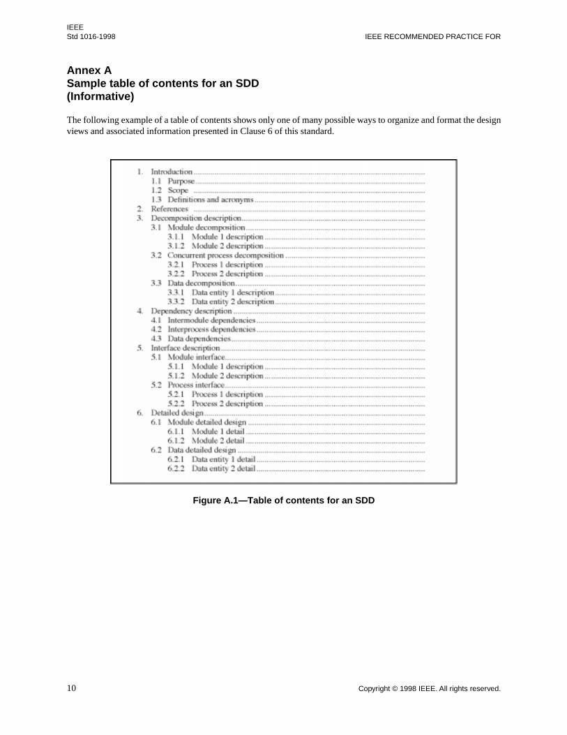
Annex A Sample table of contents for an SDD(Informative)
The following example of a table of contents shows only one of many possible ways to organize and format the designviews and associated information presented in Clause 6 of this standard.
Figure A.1—Table of contents for an SDD

Copyright © 1998 IEEE. All rights reserved. 11
IEEESOFTWARE DESIGN DESCRIPTIONS Std 1016-1998
Annex B Guidelines for compliance with IEEE/EIA 12207.1-1997(Informative)
B.1 Overview
The Software Engineering Standards Committee (SESC) of the IEEE Computer Society has endorsed the policy ofadopting international standards. In 1995, the international standard, ISO/IEC 12207, Information technology—Software life cycle processes, was completed. The standard establishes a common framework for software life cycleprocesses, with well-defined terminology, that can be referenced by the software industry.
In 1995 the SESC evaluated ISO/IEC 12207 and decided that the standard should be adopted and serve as theinternational basis for life cycle processes within the IEEE Software Engineering Collection. The IEEE adaptation ofISO/IEC 12207 is IEEE/EIA 12207.0-1996. It contains ISO/IEC 12207 and the following additions: improvedcompliance approach, life cycle process objectives, life cycle data objectives, and errata.
The implementation of ISO/IEC 12207 within the IEEE also includes the following:
IEEE/EIA 12207.1-1997, IEEE/EIA Guide for Information Technology—Software life cycle processes—Life cycle data;
IEEE/EIA 12207.2-1997, IEEE/EIA Guide for Information Technology—Software life cycle processes—Implementation considerations; and
Additions to 11 SESC standards (i.e., IEEE Stds 730, 828, 829, 830, 1012, 1016, 1058, 1062, 1219, 1233, and1362) to define the correlation between the data produced by existing SESC standards and the data producedby the application of IEEE/EIA 12207.1-1997.
NOTE — Although IEEE/EIA 12207.1-1997 is a guide, it also contains provisions for application as a standard with specificcompliance requirements. This annex treats IEEE/EIA 12207.1-1997 as a standard.
In order to achieve compliance with both this standard and IEEE/EIA 12207.1-1997, it is essential that the user reviewand satisfy the data requirements for both standards.
When this standard is directly referenced, the precedence for conformance is based upon this standard alone. Whenthis standard is referenced with the IEEE/EIA 12207.x standard series, the precedence for conformance is based uponthe directly referenced IEEE/EIA 12207.x standard, unless there is a statement that this standard has precedence.
B.1.1 Scope and purpose
Both this standard and IEEE/EIA 12207.1-1997 place requirements on an SDD. The purpose of this annex is to explainthe relationship between the two sets of requirements so that users producing documents intended to comply with bothstandards may do so.
B.2 Correlation
This clause explains the relationship between this standard and IEEE/EIA 12207.0-1996 in the following areas:terminology, process, and life cycle data.
B.2.1 Terminology correlation
The two standards, IEEE/EIA 12207.0-1996 and IEEE Std 1016-1998, make different assumptions about thenomenclature describing the results of the design activity.

12 Copyright © 1998 IEEE. All rights reserved.
IEEE Std 1016-1998 IEEE RECOMMENDED PRACTICE FOR
IEEE/EIA 12207.0-1996 takes a project management or acquisition view. It is characterized by names for each aspectof the design and concern for levels of design. This leads in IEEE/EIA 12207.0-1996 to the following titles: SoftwareDesign Description, Software Architecture Description, Software Interface Design Description, and Data Base DesignDescription. IEEE/EIA 12207.0-1996 uses the term “software item” as the overall descriptor for a design and uses theterm “software unit” as the basic element of a design.
IEEE Std 1016-1998 separates how information of a design description is organized from how it is used. The designdescription information consists of the following: introduction, design entities, and design entity attributes. IEEE Std1016-1998 uses the term “design entity” for the basic element of a design. The design entity attributes are identity,type, purpose, function, subordinates, dependencies, interface, resources, processing, and data. IEEE Std 1016-1998uses the concept of “design views” to facilitate the access of design information from various technical viewpoints.The design views are ways of viewing the design description information. The recommended design views aredecomposition description, dependency description, interface description, and detail description.
Within IEEE Std 1016-1998 a design entity could be used to capture an SDD, software architecture description,software interface design description, or data base design description.
B.2.2 Process correlation
IEEE/EIA 12207.1-1997 is based on the life cycle view of IEEE/EIA 12207.0-1996. It has a strong process bias. It isparticularly focused toward acquisition and has detailed process requirements. In contrast, IEEE Std 1016-1998 placesno requirements on process. It does, however, make process assumptions. Its process focus is on achieving designintegrity.
B.2.3 Life cycle data correlation for SDDs
The information required in an SDD by this recommended practice and the information required in an SDD by IEEE/EIA 12207.1-1997 are similar. It is reasonable to expect that a single document could comply with both standards. Themain difference is that this recommended practice prescribes an information model for relating the elements of adesign, while IEEE/EIA 12207.1-1997 does not. Details are provided in Clause B.3.
B.2.4 Life cycle data correlation between other data in IEEE/EIA 12207.1-1997 and IEEE Std 1016-1998
Table B.1 correlates the life cycle data other than SDDs between IEEE/EIA 12207.1-1997 and IEEE Std 1016-1998.It provides information to users of both standards.
Table B.1—Life cycle data correlation between other data in IEEE/EIA 12207.1-1997 and IEEE Std 1016-1998
Information item(s)IEEE/EIA 12207.0-
1996 subclauseKind of
documentationIEEE/EIA 12207.1-
1997 subclause
Corresponding clause of
IEEE Std 1016-1998
Database design description
5.3.5.3, 5.3.6.3, 5.3.7.1
Description 6.4 5, 6.2.1
Software architecture description
5.3.5.1, 5.3.5.6 Description 6.12 5, 6.2.2
Software interface design description
5.3.5.2, 5.3.6.2 Description 6.19 5, 6.2.3

Copyright © 1998 IEEE. All rights reserved. 13
IEEESOFTWARE DESIGN DESCRIPTIONS Std 1016-1998
B.3 Document compliance
This clause provides details substantiating a claim that an SDD complying with IEEE Std 1016-1998 may achieve“document compliance” with the SDD prescribed in IEEE/EIA 12207.1-1997. The requirements for documentcompliance are summarized in a single row of Table 1 of IEEE/EIA 12207.1-1997. That row is reproduced in Table B.2.
Table B.2—Summary of requirements for an SDDexcerpted from Table 1 of IEEE/EIA 12207.1-1997
The requirements for document compliance are discussed in the following subclauses:
B.3.1 discusses compliance with the information requirements noted in column 2 of Table B.2 as prescribedby 5.3.6.1 and 5.3.6.7 of IEEE/EIA 12207.0-1996.
B.3.2 discusses compliance with the generic content guideline (the “kind” of document) noted in column 3 ofTable B.2 as a “description.” The generic content guidelines for a “description” appear in 5.1 of IEEE/EIA12207.1-1997.
B.3.3 discusses compliance with the specific requirements for an SDD noted in column 4 of Table B.2 asprescribed by 6.16 of IEEE/EIA 12207.1-1997.
B.3.4 discusses compliance with the life cycle data objectives of Annex H of IEEE/EIA 12207.0-1996 asdescribed in 4.2 of IEEE/EIA 12207.1-1997.
B.3.1 Compliance with information requirements of IEEE/EIA 12207.0-1996
The information requirements for an SDD are those prescribed by 5.3.6.1 and 5.3.6.7 of IEEE/EIA 12207.0-1996. Therequirements are substantively identical with those considered in B.3.3 of this recommended practice.
B.3.2 Compliance with generic content guidelines of IEEE/EIA 12207.1-1997
The generic content guidelines for a “description” in IEEE/EIA 12207.1-1997 are prescribed by 5.1 of IEEE/EIA12207.1-1997. A complying description shall achieve the purpose stated in 5.1.1 and include the information listed in5.1.2 of IEEE/EIA 12207.1-1997.
The purpose of a description is as follows:
IEEE/EIA 12207.1-1997, subclause 5.1.1: Purpose: Describe a planned or actual function, design,performance, or process.
An SDD complying with IEEE Std 1016-1998 would achieve the stated purpose.
Any description complying with IEEE/EIA 12207.1-1997 shall satisfy the generic content requirements provided in5.1.2 of that standard. Table B.3 of this recommended practice lists the generic content items and, where appropriate,references the clause of this recommended practice that requires the same information. It may be concluded that the
Information item(s)
IEEE/EIA 12207.0-1996
subclauseKind of
documentation
IEEE/EIA 12207.1-1997
subclause References
Software design description
5.3.6.1, 5.3.6.7 Description 6.16 IEEE Std 1016-1998;IEEE Std 1016.1-1993;EIA/IEEE J-STD 016-1995, G.2.4; see also ISO/IEC 5806, 5807, 6593, 8631, 8790, and 11411 for guidance on use of notations

14 Copyright © 1998 IEEE. All rights reserved.
IEEE Std 1016-1998 IEEE RECOMMENDED PRACTICE FOR
information required by recommended practice is sufficient for compliance except as noted in the third column ofTable B.3.
This recommended practice makes the assumption that project-specific data would be contained in other records.Examples of such data include the date of issue and status, issuing organization, and change history.
Table B.3—Coverage of generic description requirements by IEEE Std 1016-1998
B.3.3 Compliance with specific content requirements of IEEE/EIA 12207.1-1997
The specific content requirements for an SDD in IEEE/EIA 12207.1-1997 are prescribed by 6.16 of IEEE/EIA12207.1-1997. A compliant SDD shall achieve the purpose stated in 6.16.1 and include the information listed in 6.16.3of IEEE/EIA 12207.1-1997.
The purpose of the SDD is as follows:
IEEE/EIA 12207.1-1997, Clause 6.16.1: Purpose: Describe the design of a software item. Along withthe software architecture, it provides the detailed design needed to implement the software. It may besupplemented by software item interface design and database design.
An SDD complying with IEEE/EIA 12207.1-1997 shall satisfy the specific content requirements provided in 6.16.3 ofthat standard. Table B.4 of this recommended practice lists the specific content items and, where appropriate,references the clause of this recommended practice that requires the same information. The third column listsinformation that shall be added in order to comply with the generic content requirements.
IEEE/EIA 12207.1-1997generic content
Corresponding clause of IEEE Std 1016-1998
Additions to requirements of IEEE Std 1016-1998
a) Date of issue and status — See note.
b) Scope (Suggested for inclusion in an SDD; see Annex A,1.2 Scope)
Scope shall be provided for an SDD.
c) Issuing organization — See note.
d) References — References used in preparing the SDD shall be included in an SDD.
e) Context 4. Considerations for producing a software design description
A discussion of the context for the SDD shall be included in an SDD.
f) Notation for description 6. Design description organization A discussion of the notation used for the design descriptions shall be included in an SDD.
g) Body 5. Design description information content
—
h) Summary — A summary shall be provided for an SDD.
i) Glossary — A glossary of terms used shall be provided in an SDD.
j) Change history — See note.
NOTE — IEEE Std 1016-1998 assumes this data is present in project files; for example, configuration status data.

Copyright © 1998 IEEE. All rights reserved. 15
IEEESOFTWARE DESIGN DESCRIPTIONS Std 1016-1998
Table B.4—Coverage of specific plan requirements by IEEE Std 1016-1998
B.3.4 Compliance with life cycle data objectives
In addition to the content requirements, life cycle data shall be managed in accordance with the objectives provided inAnnex H of IEEE/EIA 12207.0-1996.
NOTE — The information items covered by this recommended practice include plans and provisions for creating software lifecycle data related to the basic “design data” in H.4 of IEEE/EIA 12207.0-1996. It provides for the following design data:architecture, algorithms, design constraints, mapping to requirements, and key decision rationale.
IEEE/EIA 12207.1-1997 specific content
Corresponding clauses ofIEEE Std 1016-1998
Additions to requirements of IEEE Std 1016-1998
6.16.3 a) Generic description information
— —
6.16.3 b) Description of how the software item satisfies the software requirements...
5.3.3 Purpose —
... , including algorithms …, 5.3.9 Processing —
… , data structures 5.3.10 Data —
6.16.3 c) Software item input/output description;
5.3.7 Interface —
6.16.3 d) Static relationships of software units;
5.3.5 Subordinates 5.3.6 Dependencies 5.3.8 Resources
—
6.16.3 e) Concept of execution, … 5.3.7 Interfaces 5.3.8 Resources
—
... including data flow ... 5.3.6 Dependencies —
... and control flow...; 5.3.6 Dependencies —
6.16.3 f) Requirements traceability, ...
5.3.3 Purpose 5.3.5 Subordinates
—
6.16.3 f) (i) Software component-level requirements traceability
5.3.3 Purpose —
6.16.3 f) (ii) Software unit-level requirements traceability
5.3.3 Purpose —
6.16.3 g) Rationale for software item design
5.3.3 Purpose —
6.16.3 h) Reuse element identification
— The reuse element identification shall be included in the SDD.
6.16.4 b) Define types of errors and their handling which are not specified in the software requirements
5.3.7 Interfaces 5.3.8 Resources 5.3.9 Processing
—

16 Copyright © 1998 IEEE All rights reserved
IEEE Std 1016-1998
B.4 Conclusion
The analysis documented in this annex suggests that any SDD complying with this recommended practice and theadditions shown in Table B.3 and Table B.4 also complies with the requirements of an SDD in IEEE/EIA 12207.1-1997. In addition, to comply with IEEE/EIA 12207.1-1997, an SDD shall support the life cycle data objectives ofAnnex H of IEEE/EIA 12207.0-1996.