ieee rtpge information
TRANSCRIPT
IEEE RTPGE informationAnswers to PoE and Channel Model ad hoc
Stefan Buntz, Thilo Streichert, RD/ESA
additional/updated questions from RTPGE
Stefan Buntz, Thilo Streichert, RD/ESA 2
Adobe Acrobat
Document
PoE Ad-hoc questionaire
Adobe Acrobat
Document
Channel Ad-hoc questionaire
http://www.ieee802.org/3/RTPGE/email/pdf0CEXtJtDjK.pdf http://www.ieee802.org/3/RTPGE/email/pdfVRBHUACjGc.pdf
Should be answerd by the automotive OEMs, latest to the next IEEE meeting in
San Diego (16th of July).
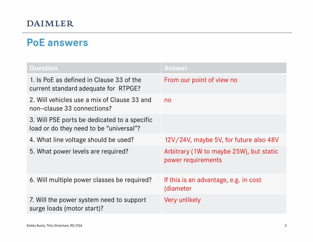
PoE answers
Question Answer
1. Is PoE as defined in Clause 33 of the
current standard adequate for RTPGE?
From our point of view no
2. Will vehicles use a mix of Clause 33 and
non--clause 33 connections?
no
3. Will PSE ports be dedicated to a specific
load or do they need to be “universal”?
4. What line voltage should be used? 12V/24V, maybe 5V, for future also 48V
5. What power levels are required? Arbitrary (1W to maybe 25W), but static
power requirements
6. Will multiple power classes be required? If this is an advantage, e.g. in cost
(diameter
7. Will the power system need to support
surge loads (motor start)?
Very unlikely
Stefan Buntz, Thilo Streichert, RD/ESA 3

PoE answers
Question Answer
8. What are the isolation requirements? Not sure about?
9. What action should a PSE take if a power
fault is detected?
Switch to save state and report to
diagnosis (e.g. register)
10. Is a chassis ground always available? No, e.g. in mirrors
11. Will we need to support
adding/subtracting nodes to/from a live
system (for example, a vehicle trailer or
customer--installed equipment)?
Very unlikely
12. What is the maximum length of a PoE
segment?
Same like others (15m / 40m)
13. Will PoE channels be treated differently
(e.g., different wire gauge) than non-- PoE
channels?
If this is an advantage, e.g. in cost
(diameter)
Stefan Buntz, Thilo Streichert, RD/ESA 4

PoE answers
Question Answer
14. Do we need to support daisy--chain
configurations?
unlikely
15. What is the estimated ratio of powered
to unpowered ports?
There will be more unpowered ports
Stefan Buntz, Thilo Streichert, RD/ESA 5

Answers to Automotive cabling survey
• Your Name: Helmut Leier, Thilo Streichert, Stefan Buntz
Your Company Name: Daimler AG
City/State/Zip: Germany, Ulm, Wilhelm-Runge-Strasse 11
E-MAIL: [email protected]
Your Job Function: Research/Development Engineer
2. Wire harness or assembly topology (see Figure 1).
2.1 Maximum length in meters of wire harness or assembly between active electronic devices – report current applications and lengths
[EC] to [EC]. car/van:12m, truck/bus: 32m
2.2 Maximum length in meters of wire harness or assembly between active electronic devices – report future applications and lengths
[EC] to [EC]. car/van:15m, truck/bus: 40m
2.3 Number and type of inline connectors [C] between active electronic devices – report current applications.
number of connectors 3 type of connector(s) typical connectors are Tyco (TE) MQS, nanoMQS, MLK, … different multi-pin connectors
within one link are possible
2.4 Number and type of inline connectors [C] between active electronic devices– report future applications.
number of connectors 3 type of connector(s) typical connectors are Tyco (TE) MQS, nanoMQS, MLK, … different multi-pin connectors
within one link are possible
2.5 Type of active electronic connectors [AEC] – report current applications.
type of connector(s) typical connectors are Tyco (TE) MQS, nanoMQS, MLK, …
2.6 Type of active electronic connectors [AEC] – report future applications.
type of connector(s) typical connectors are Tyco (TE) MQS, nanoMQS, MLK, …
Stefan Buntz, Thilo Streichert, RD/ESA 6

Answers to Automotive cabling survey
2.7 Are there requirements for future applications to be mechanically compatible to existing connector systems?
not necessarily
2.8 Are there requirements for mechanically compatible connector systems between automobile manufacturers?
Not necessarily, however due to same requirements and cost aspects same connector is likely
3. Balanced twisted-pair cable used in wire harness or assembly (see Figure 1 and Figure 2.) report parameters and values.
3.1 Current automotive applications
• Gauge [AWG] [or conductor in mm]
• Impedance [ohm +/- ]
• Shield [Y/N] [shield type]
• Copper conductors [Y/N] solid [Y/N] stranded [#strands]
• Direct current resistance [milliohm/meter]
3.2 Future automotive applications
• Gauge [AWG] [or conductor in mm]
• Impedance [ohm +/- ]
• Shield [Y/N] [shield type]
• Copper conductors [Y/N] solid [Y/N] stranded [#strands]
• Direct current resistance [milliohm/meter]
See next slide
Stefan Buntz, Thilo Streichert, RD/ESA 7

Answers to Automotive cabling survey
4. Bundled cable types in wire harnesses or assemblies (Figure 1)
4.1 Report data rates and signaling schemes for differential signaling applications in bundle [data rates and signaling].
See next slide
4.2 Report other data rates and signaling schemes not using differential signaling in bundle [data rates and signaling].
See next slide
4.3 Report voltage/power in bundle [ ]
12V (cars), 24V (trucks, busses) and 48V (future supply voltage)
currents are up to 150A@12V (e.g. steering, air condition, …).
5. External noise sources see following slides
5.1 Report steady state noise (including frequency content)
5.2 Report time variable noise (things that come and go)
5.3 Report impulse noise
5.4 Report radio frequency interference - modulated signals (i.e., cell phone type signals)
Stefan Buntz, Thilo Streichert, RD/ESA 8

Typical automotive bus systems and cabeling
• Overview over typical automotive bus systems, their voltage levels and cables and connectors
Stefan Buntz, Thilo Streichert, RD/ESA 9
system LIN CAN(500
kbit/s*)
FlexRay USB
(HiSpeed)
HSVL
(„LVDS“)
RF-signals
Data rate 20 kbit/s 500 kbit/s 10 Mbit/s 480 Mbit/s 200…3000 Mbit/s Antenna signals(AM, FM, ISM, WLAN, Bluetooth,
…)
amplitude 12 V 2V 0,6V 0,4V 0,25…0,45V different
differential? single-ended differential differential differential differential single-ended
typical cabling Single wire,
e.g. 0,35mm²
UTP 2x0,35mm² UTP (e.g. FLR9Y 2x0,35 mm²-SN)
STQ 4x0,5mm² (e.g.
Leoni Dacar566)
STQ 4x0,14mm² (e.g. Leoni Dacar535-2)
Coax(e.g. Leoni Dacar302)
Differential Cable
impedance (Zdiff ΩΩΩΩ)
- 120 (±12) 100 (±10) 90 (±15) 100 (±15) 50 (±3)
Shield? no no no yes (braid + foil) yes (braid + foil) yes (braid + foil)
conductor stranded
(e.g. 7)
Stranded
(e.g. 7)
stranded
(e.g. 7x0,26)
stranded
(e.g. 19x0,182)
stranded
(e.g. 7x0,16)
stranded
(e.g. 7x0,27)
Jacketed? - no no yes yes yes
typical connector different multi pin
connectors
(e.g. Tyco MQS)
different multi pin
connectors
(e.g. Tyco MQS)
different multi pin
connectors
(e.g. Tyco MQS)
Rosenberger HSD Rosenberger HSD FAKRA
*) different data rates are possible for CAN, typically are 125kbit/s or 500kbit/s

Typical requirements MBN10284-2:2011-04
• Overall requirements (Step size, measurement time, BW)
• RF Emissions – antenna test
according to CISPR25, section 6.4
limit diagrams for different BW/detectors (see next slide)
Stefan Buntz, Thilo Streichert, RD/ESA 10
BW
(kHz)
PK QP AV
Max. frequency
step size
Min. measurement
time (ms)
Max. frequency
step size
Min. measurement
time (ms)
Max. frequency
step size
Min. measurement
time (ms)
9 ≤0,5 x BW 50 ≤5 x BW 1000 ≤0,5 x BW 50
120 ≤0,5 x BW 5 ≤5 x BW 1000 ≤0,5 x BW 5
1000 ≤0,5 x BW 50 - - ≤0,5 x BW 50

Typical requirements MBN10284-2:2011-04
limit diagrams for different BW/detectors
antenna test, according to CISPR25, section
6.4 (~1,7m cable, 1m in front of antenna)
always lowest limit is valid.
Stefan Buntz, Thilo Streichert, RD/ESA 11
100k 1M 10M 100M 1G 3G
-20
0
20
40
60
80
el.
Fe
ldst
ärk
e [
dB
µV
/m]
Frequenz [Hz]
(PK) limits MBN10284: 120 kHz MaxPeak; 5 ms/pt
(QP) limits MBN10284: 120 kHz QuasiPeak; 1 s/pt
(AV) limits MBN10284: 120 kHz Average; 5 ms/pt
100k 1M 10M 100M 1G 3G
-20
0
20
40
60
80
el.
Fe
ldst
ärk
e [
dB
µV
/m]
Frequenz [Hz]
(PK) limits MBN10284: 1 MHz MaxPeak; 50 ms/pt
(QP) no limits for Quasi-Peak-Detector at 1 MHz RBW
(AV) limits MBN10284: 1 MHz Average; 50 ms/pt
Limits for 120kHz BW Limits for 1000kHz BW
Limits for 9kHz BW

Typical requirements MBN10284-2:2011-04
• Bulk Current injection (BCI)
acc. to ISO/DIS11452-4:2010-1
test currents see table on the
right.
In the formulas, f is the frequency
in MHZ and lg denotes the
logarithm to the base 10
Stefan Buntz, Thilo Streichert, RD/ESA 12
Frequency
Range
(MHz)
Test Current
(dBµA)
Modulation
0,1 … 2,38 90
CW
and
AM (1 kHz, 80%)
2,38 … 15 106 – 20 lg (15/f)
15 … 30 106
30 … 54 106
54 … 65 100 – 10 lg (f/88)
65 … 88 106
88 … 140 100 – 10 lg (f/88)
140 … 174 106 – 10 lg (f/88)
174 … 380 97
380 … 400 106 – 10 lg (f/88)

Typical requirements MBN10284-2:2011-04
• RF radiated immunity (ALSE test)
acc. to ISO/DIS 11452-2:2004-11
Stefan Buntz, Thilo Streichert, RD/ESA 13
Frequency
Range (MHz)
Test level
(V/m)
Polarisation Modulations
200 … 380 70 vert + hor CW and AM (1kHz, 80%)
380 … 460 140 vert + hor CW and AM (1kHz, 80%)
460 … 806 70 vert + hor CW and AM (1kHz, 80%)
806 … 915 140 vert + hor CW and pulse modulation (577µs duration, 217Hz repetition rate)
915 … 1200 70 vert + hor CW
1200 … 1400 140 vert + hor CW and pulse modulation (3µs duration, 300Hz repetition rate)
1400 … 1710 70 vert + hor CW
1710 … 1910 140 vert + hor CW and pulse modulation (577µs duration, 217Hz repetition rate)
1910 … 2700 70 vert + hor CW
2700 … 3000 140 vert + hor CW and pulse modulation (3µs duration, 300Hz repetition rate)

Typical requirements MBN10284-2:2011-04
• Magnetic field immunity acc. to
ISO 11452-8:2007-07
• transient pulses on data lines acc. to ISO7637-3:
• Slow transient with inductive coupling (ICC), requirement: ±6V,
• Fast Transient with capacitive coupling (CCC), requirement: -75V/+60V
Stefan Buntz, Thilo Streichert, RD/ESA 14
Frequency
Range (MHz)
Test level
(A/m)
Modulation
0 (DC) 1000 DC
0,015 … 0,06 1000 CW
0,06 … 6 60/f CW
6 … 30 10 CW

Typical requirements MBN10284-2:2011-04
• ESD requirements
• ESD Handling Test acc. to ISO10605:2008-07, section 9 (150pF, 330Ω)
• ESD Direct Discharge acc. to ISO 10605:2008-07, Annex F (330pF, 330Ω)
• ESD Indirect Discharge acc. to ISO 10605:2008-07, Annex F (330pF, 330Ω)
Stefan Buntz, Thilo Streichert, RD/ESA 15
Discharge type pins Housing
Discharge points Plastics Discharge points Plastics
Air discharge - 10 discharges
±4kV, ±8kV and ±15kV
10 discharges
±15kV
Contact discharge 3 discharges
±2kV, ±4kV and ±6kV
- 5 discharges
±4kV and ±8kV
Discharge type pins Housing, periphery, switches, displays, …
Discharge points Plastics Discharge points Plastics
Air discharge - 10 discharges
±4kV, ±8kV and ±15kV
10 discharges
±15kV
Contact discharge 3 discharges
±2kV, ±4kV and ±6kV
- 10 discharges
±4kV and ±8kV
Discharge type Discharge islands
Air discharge -
Contact discharge 10 discharges
±4kV, ±8kV and ±15kV

Open questions/issues
• The above shown EMC requirements describe the overall performance. For
the individual System Components (PHY/Filtering/PCB/Connectors/Cables)
dedicated requirements must be derived.
• Therefore we see the need that chip designers derive the respective
requirements for the other system components out of their solution.
e.g. How much unsymmetry (TLC, TLTC) does the (planned) chip/system
allow in order to still fullfill the shown requirements?
Stefan Buntz, Thilo Streichert, RD/ESA 16

1717
overview / parts of the cable harness
• engine harness
• cockpit-harness
• Powertrain harness
examples of connectors
TDR measurements (impedance)
S-parameter measurements
exemplary automotive cable harness
Stefan Buntz, Thilo Streichert, RD/ESA
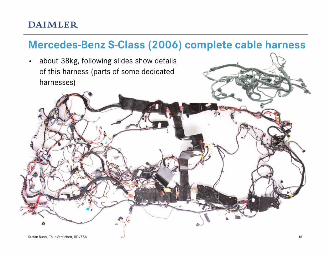
Mercedes-Benz S-Class (2006) complete cable harness
• about 38kg, following slides show details
of this harness (parts of some dedicated
harnesses)
Stefan Buntz, Thilo Streichert, RD/ESA 18
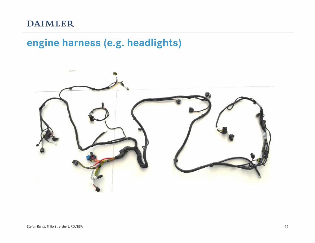
19
engine harness (e.g. headlights)
Stefan Buntz, Thilo Streichert, RD/ESA

20
cockpit harness
Stefan Buntz, Thilo Streichert, RD/ESA
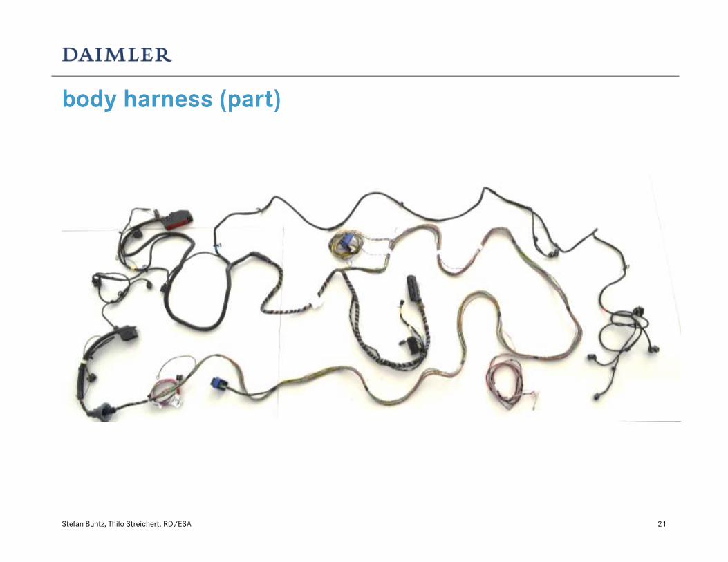
21
body harness (part)
Stefan Buntz, Thilo Streichert, RD/ESA

22
connector examples (CAN star coupler)
• CAN cables:
70mm of untwisted cable
7 cm
Stefan Buntz, Thilo Streichert, RD/ESA

connector examples
Stefan Buntz, Thilo Streichert, RD/ESA 23

24
TDR measurements
• CAN connection of headlights (engine compartment, no inline connectors)
• cable harness 50mm above GND, no inline connectors
Stefan Buntz, Thilo Streichert, RD/ESA

25
TDR measurements
ca. 1.80m ca. 4.00m
Stefan Buntz, Thilo Streichert, RD/ESA

26
S-Parameter Port3
Port4Port1
Port2
ca. 1.80m
Stefan Buntz, Thilo Streichert, RD/ESA
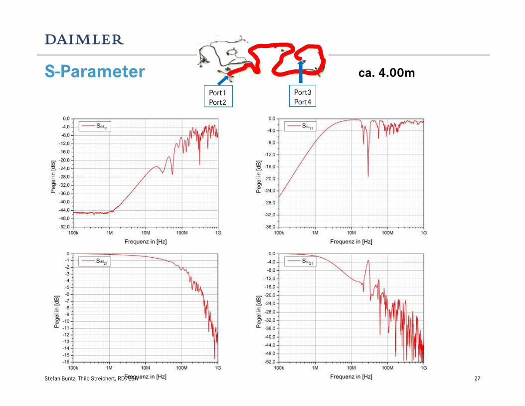
27
S-ParameterPort3
Port4
Port1
Port2
ca. 4.00m
Stefan Buntz, Thilo Streichert, RD/ESA

S-parameter with (simple) in-line-connector
Port 1
Stefan Buntz, Thilo Streichert, RD/ESA 28
In-Line-Stecker Port 2
ca. 5.60m ca. 2.10m
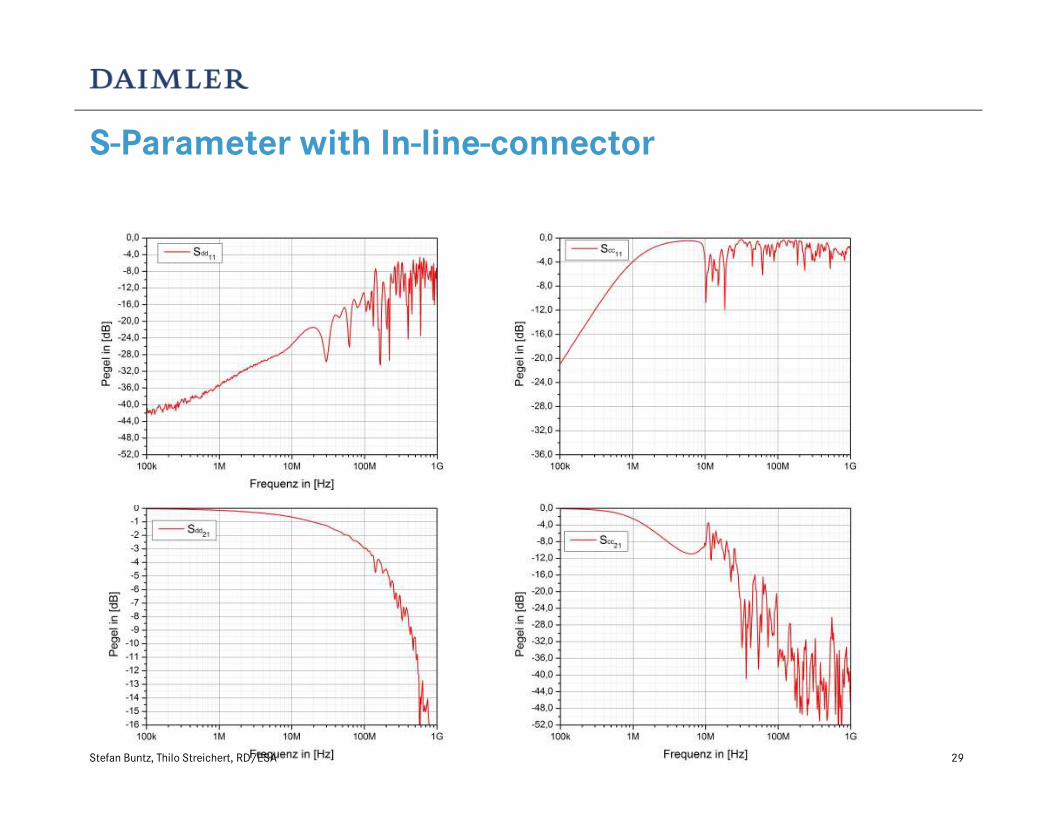
29
S-Parameter with In-line-connector
Stefan Buntz, Thilo Streichert, RD/ESA

summary
• The shown pictures are just examples of an automotive cable harness
• The shown s-Parameter measurements are also just examples (and by way not
the „worst case“) of how an automotive channel coul look like.
Stefan Buntz, Thilo Streichert, RD/ESA 30
Automotive requirements for Connector
• a multi-pin connector must be possible (e.g. similar to MQS)
• A possibility for contacting shielded cables must be possible inside the multi-
pin connector
Stefan Buntz, Thilo Streichert, RD/ESA 31