ieee transactions on antennas and … · traditional analysis work was extended to include...
TRANSCRIPT

IEEE TRANSACTIONS ON ANTENNAS AND PROPAGATION, VOL. 61, NO. 5, MAY 2013 2695
Rapid Surface-Wave Dispersion and Plane-WaveReflection Analyses of Planar Corrugated Surfacesby Asymptotic Corrugations Boundary Conditions
Even for Oblique Azimuth PlanesMalcolm Ng Mou Kehn, Member, IEEE
Abstract—The asymptotic corrugations boundary condition(ACBC) is used together with classical theory of vector potentialsto analyze planar corrugations. A transcendental characteristicequation is derived, from which the dispersion diagram can beobtained, thereby conveying surface wave passband and stopbandproperties, even for propagation within oblique azimuth planesas well as both principal TE and TM polarizations. From theformulation, field distributions for the regions within the groovesand above the corrugations can also be generated. When com-pared with the dispersion graphs obtained from characteristicequations derived by the classical transverse resonance technique(TRT), the newly presented ACBC method provides superioraccuracy. Explicit formulas for the complex reflection coefficient(amplitude and phase) for both TE and TM polarized plane-waveincidences are also derived as closed-form analytic functions ofall parameters (especially the azimuth phi angle of incidence)using a novel concept of unusual transversely phased plane-waves.These proposed approaches are massively more efficient thanfull-wave solvers, providing unparalleled speedup of computationby thousands of times. The surface-wave and reflection propertiesof planar corrugations are thus herein analyzed in a unified,complete, and elegant manner that is also highly efficient but yetaccurate. This thorough work is thus a great boost to the con-tinued use of corrugated surfaces as artificial magnetic conductors(AMC), electromagnetic bandgap (EBG) structures, and soft/hardsurfaces in all walks of antenna design, especially in terms of speedand accuracy.
Index Terms—Asymptotic corrugations boundary condition(ACBC), corrugations, dispersion diagram, electromagneticbandgap (EBG) surfaces.
I. INTRODUCTION
P LANAR corrugated surfaces have been a subject of keeninterest amongst purists in electromagnetic theory for
many decades [1]–[7]. With the advent of the digital computer,traditional analysis work was extended to include numericaltreatments of plane-wave scattering from corrugations [8]–[10].
Manuscript received July 31, 2012; revised November 21, 2012; acceptedDecember 26, 2012. Date of publication January 03, 2013; date of current ver-sion May 01, 2013. This work was supported by the National Science Councilof Taiwan.The author is with the National Chiao Tung University, Hsinchu 30010,
Taiwan (e-mail: [email protected]).Color versions of one or more of the figures in this paper are available online
at http://ieeexplore.ieee.org.Digital Object Identifier 10.1109/TAP.2013.2237742
Theoreticians and computational enthusiasts were not the onlyones captivated by this structure. Experimentalists and practicalengineers have, likewise for the past many years, been makinguse of corrugations to develop improved microwave devicessuch as waveguides and antennas. Possibly the most distinctand important utility of corrugated surfaces is in realizing softand hard surfaces [11], which provide bountiful applications[12], [13].By providing an approximate relationship between the
electric and magnetic field on a chosen surface, approxi-mate boundary conditions (ABC) have proven effective forsimplifying both analytical and numerical solutions of electro-magnetic wave problems [14], [15]. Among the simplest kind isthe standard impedance boundary condition (IBC), whose accu-racy was improved by the extension to generalized impedanceboundary conditions (GIBC). The works of [16]–[18] usedsuch approximate impedance boundary conditions to studycorrugated surfaces. In a related way, the asymptotic strip andcorrugations boundary conditions (ASBC and ACBC) were in-troduced in [19] to treat strip-gratings and corrugations rapidly,which provide exact solutions as the periods tend to zero.Despite these cited works, none has studied corrugated sur-
faces in terms of the dispersion diagram conveying the sur-face-wave properties especially for oblique azimuth propaga-tion directions, or presented accurate characteristic equationsfrom which such a diagram is obtained. Field distributions ofthe surface wave modes supported by the corrugations are alsonowhere to be found. To the author’s knowledge, neither arethere publications on investigations into the reflection proper-ties of planar corrugations, not even for the principal azimuthplanes of incidences, let alone oblique ones. To conduct suchstudies would prove essential for a more thorough characteri-zation of high-impedance surfaces (HIS) and artificial magneticconductors (AMC) composed of such corrugated surfaces as op-posed to just reflection studies of only the two principal azimuthplanes.In this work, planar corrugations of infinite extent shall be
analyzed using the ACBC in conjunction with classical vectorpotential analysis, leading to the derivation of a transcendentalcharacteristic equation, from which the surface-wave banddiagrams can be generated for the principal direction (per-pendicular to the grooves/ridges) as well as oblique azimuthangles of propagation. Surface-wave modal field distributionsof the corrugated surface obtainable by the formulation shall
0018-926X/$31.00 © 2013 IEEE

2696 IEEE TRANSACTIONS ON ANTENNAS AND PROPAGATION, VOL. 61, NO. 5, MAY 2013
Fig. 1. Infinitely long corrugations of infinite expanse.
also be presented. The transverse resonance technique (TRT) isan alternative for deriving the characteristic equations for TMmodes of the planar corrugated structure for the principal (per-pendicular to the ridges) and oblique directions of surface-wavepropagation, solving of which also generates the dispersiondiagram. It will however be demonstrated that the accuracyof this TRT for oblique azimuth directions of surface-wavepropagation is poor. We shall herein show that our new methodbased on ACBC overcomes this inadequacy and providesextremely accurate dispersion diagrams. In addition, by usinga novel concept of considering unusual transversely phasedplane-waves, closed-form analytic expressions for the complexreflection coefficient of both TM and TE polarized plane-waveincidence shall be derived as functions of all parameters,especially the azimuth (incidence angle as well. Numericalresults computed for both the dispersion and reflection-phasediagrams will be presented, all of which are validated by twofull-wave solvers: 1) commercial software CST MicrowaveStudio, and 2) a self-developed moment-method code [20].It will also be shown that this ACBC method is innumerablyfaster in computation speed than these full-wave solvers, bythousands of times.
II. THEORY AND FORMULATION
Consider the planar corrugated surface of Fig. 1, which is par-allel to the plane with periodicity along and perpendic-ular direction along . The period and depth of the corrugationsare and , respectively. The width of each groove along is. The permittivity and permeability of the material filling thegroove are and , whereas and representthe parameters of the upper half-space above the corrugations.In the following field expressions, a universalterm has been included to represent the component of surfacewave propagation along the direction, where is the phaseconstant along , parallel to the grooves and ridges. This termapplies also to the fields within the grooves of the corrugationsfor phase continuity with the upper half-space region.
A. Groove Fields of Corrugations
The fields within the corrugation grooves are derived by clas-sical vector potential analyses for and modes and theenforcement of appropriate boundary conditions requiring the
vanishing of tangential electric field components on the metallicwalls of the grooves [21]. Doing so, the , and componentsof the and fields of the and modal fields withinthe groove are stated as follows:
(1)
and (2)
(3)
(4)
(5)
(6)
where
and
in which may be or . The wavenumber of the mediumfilling the groove is , with
being the angular frequency [rad/s]. represents theamplitude coefficient of the mode within the groove, and isan integer symbolizing themodal index representing the numberof half-cycle variations along .With phase continuity being thereason, is the universal wavenumber along shared by boththe presently considered groove region as well as the upper-halfspace above the corrugations (the latter as elaborated in the nextsubsection). is the wavenumber along in the groove forthe mode. Obviously, all subscripts or superscripts “groove”signify that their associated quantities pertain to the groove re-gion. The symbols and are introduced to abbreviate thenotation.
B. Modal Fields Within Upper Half-Space Above Corrugations
Likewise, by vector potential analysis as well, the variouscomponents of the and fields of the and modal

NG MOU KEHN: RAPID SURFACE-WAVE DISPERSION AND PLANE-WAVE REFLECTION ANALYSES 2697
fields in the upper half-space region above the corrugations arestated as follows:
(7)
and (8)
(9)
(10)
(11)
where and represent the amplitude coefficientsof the TE and TM modes, respectively, in the upper half-spaceabove the corrugated surface. Similar to the groove region,
and are the wavenumbers along in the upperhalf-space region for the TE and TMmodes, respectively. Like-wise, and are the corresponding wavenumbersalong . As obvious as before, all subscripts or superscripts“above” indicate that their associated quantities pertain to theupper half-space region above the corrugations.
C. Asymptotic Corrugations Boundary Conditions (ACBC)
Defining first the unit vector parallel and orthogonal to thecorrugations as and , respectively, which for our configura-tion of Fig. 1 are and , the asymptotic corrugations boundaryconditions (ACBC) are stated as follows:
(12)
(13)
(14)
(15)
where
noting the incorporated subscripts TE and TM to the integermodal index to distinguish between the mode types. Now,coming to a crucial step, assume and in thegrooves, i.e., existence of only the dominant (TEM)
mode and absence of all TM modes, thereby having just simplyin place of in (12) and (14).
For (12), it is observed, respectively from the upper equation of(1) and the lower equation of (4) that
and (16)
are already satisfied by the and conditionsunder ACBC. As for (13), we require
(17)
where the upper equation of (7) and the top one of (10) are used.By perceiving combined modal TE and TM fields as a collectivewhole, meaning that each modal group (or type) is regarded asa superposed entirety already encompassing all its componentfields, but each sharing a common phaseterm, the phase constants along the and directions parallelto the surface are universal, i.e., and
in order for phase continuity across theinterface. Thus,
(18)
Proceeding to (14), we require
(19)
in which the second term on the left-hand side vanishes [lowerof (6)].Using the upper equation of (3), the lower one of (7), and the
bottom one of (10):
(20)
where is the groove index, noting how the left-hand side quan-tity varies with in a stepwise manner, with each term of itssummation being a piecewise constant within the groove,i.e., .Focusing within the groove only, the summation over the
groove index in (20) is removed, resulting in
(21)
and as the period tends to zero, the factor on theright-hand side of this (21) becomes approximately ,which is a constant within (thegroove). This expresses that the continuous variation with canbe approximated as a piecewise discrete constant over the

2698 IEEE TRANSACTIONS ON ANTENNAS AND PROPAGATION, VOL. 61, NO. 5, MAY 2013
groove of nearly zero width. Hence, the resultantgets canceled out on both sides, leading to
(22)
Moving on to the final (15), we require
(23)
in which again the second term on the left-hand side vanishes[lower of (1)].Using the upper equation of (4), the top equation of (9), and
the upper one of (11),
(24)
In the same way as for (20) and (21), we have
(25)
For surface-wave along the -plane surface of the corruga-tions, and are required to be imaginary, i.e.,
and (26)
The general formula for is given by
(27)
where is the phase constant along in the groove region.But since within each groove asunder ACBC (presence of only dominant mode assumed), i.e.,
(28)
thus (27) reduces to (under ACBC)
(29)and due to the reason of collective whole mode sharing acommon pair of surface wavenumber components:and , which together constituting a certain surface wavemodal wavenumber
(30)
as explained just after (17) earlier, we may equate both modal(TE and TM) attenuation constants along the vertical direction(perpendicular to the corrugation surface) for the upper half-space region above the corrugations, i.e.,
(31)
(32)
where is positive real.
D. Transcendental Characteristic Equations
The three pertinent equations are (18), (22) and (25), and thethree unknowns are , , and , which maybe cast into a 3 3 matrix system. By setting the matrix deter-minant to zero for nontrivial solutions, we obtain the followingcharacteristic equation:
(33)
where
(34)Depending on which two of the following three quantities: 1)
frequency , 2) , and 3) , are a priori pre-fixed as known values, the third quantity remains as the only un-known in this (33), which may then be solved for as roots of thischaracteristic equation. Doing so yields the required informa-tion for plotting various path-regions of the dispersion diagram.
E. Solution of Matrix Equation for Amplitude Coefficients
Equations (18), (22), and (25) may be cast into the followingmatrix equation:
(35)
where the matrix elements need no further specification.By performing Gauss elimination, the following is obtained:
(36)
in which is any arbitrary scaling amplitude. Allmatrix elements would have become fully evaluatable upon
solving the characteristic equation of (33) for either the phaseconstant ( or ) or frequency of interest, and by substi-tuting these , , and into (1)–(11), the com-

NG MOU KEHN: RAPID SURFACE-WAVE DISPERSION AND PLANE-WAVE REFLECTION ANALYSES 2699
plete closed-form analytical expressions of the fields in both thegroove region and the half-space above the corrugations may beobtained as mathematical functions of all geometrical and ma-terial parameters of the corrugated structure.
F. Consistency With Modal Surface Impedances and InputImpedance of Shorted Transmission Line
The surface impedance looking down at towards thePEC floor of the corrugations are defined as follows:
(37)where is the familiar modal impedance
, therefore yielding the familiar input impedance ofa shorted transmission line of length and characteristicimpedance .Similarly, the input impedances looking at interface
upwards into the upper half-space region for the two modalgroups are
(38)
being the familiar modal impedance, whereas
(39)
being the familiar modal impedance
G. Refinement Factor via Period to Groove-Width Ratio
From Section II-F, and of (38) and (39) werethe impedances looking upwards into the upper half-space re-gion above the corrugations. The and in the numeratorsof the expressions for these impedances are -field componentsthat are tangential to the corrugation surface and which vanishover the top PEC surfaces of the metallic ridges. Before pro-ceeding further, it is first emphasized that the rightmost sidesof both (38) and (39), being the well-known classical expres-sions for the TE and TM modal impedances of a medium withparameters for propagation along , must alwayshold and stay unchanged (there is no reason for these imped-ances to be altered). Hence, it may be hypothesized that the tan-gential and field components ( either or ),but only on the corrugation surface: , may be correctedby an incremental ( 1) factor , where is the corruga-tion period (see Fig. 1 again) and is the groove-width. In thisway, amultiplication of these correctivelymagnified and
fields on the corrugation surface with the reduction ( 1)factor (as required by the fractional existence of the upperregion’s tangential -field components over only the aperturesof the grooves, but vanishing over the ridge-tops), neutralizesthat aforementioned incremental factor, therebymaintaining the
TE and TM modal impedances looking upwards into the upperhalf-space region above the corrugations, whichmust be preserved as explained earlier. However, this correc-tion factor, applies only to the tangentialcomponents and only just over the surface .To mathematically convey these textual descriptions, the fol-
lowing corrected tangential field components are defined:
(40)
in which denotes either or . The script correc signifiescorrected and represents E or M as before. The right-side fieldquantity is that of the original ones in (7) and the top and bottomof (10). Notice the explicit evaluation at to stress thevalidity of this correction only over the surface. Subsequently,these corrected tangential electric field components are usedfor the numerators of the surface impedance [those of (38) and(39)]:
(41)
noting the reduction factor as explained. Substitutingin (40) yields back exactly the same ones as (38) and (39),thereby maintaining their rightmost classical expressions:
and as required. Therefore, whatthis (41) says is that the upward-looking surface impedanceinvolving tangential electric field components at effec-tively uses the uncorrected tangential -fields also atgiven by the original expressions of (7) and the top and bottomof (10), thus appropriately preserving (38) and (39).As such, the key concepts are as follow. The upward sur-
face impedance [(38), (39) or (41) combined] involves tangen-tial fields of the upper half-space region as a collective wholethroughout the entire surface, since indeed the entire upper half-space may be perceived as a transmission line for propagationalong the vertical direction. The nullification of the tangen-tial electric field components of the upper half-space across themetallic ridges through the reduction factor of is thus re-quired. On the other hand, the four ACBC relations (12)–(15)are all satisfied individually over each groove aperture, in anelement-by-element fashion [see (20) and (21)]. Hence, the tan-gential electric field components of the upper half-space regionused in these boundary conditions are exempted from this re-duction factor. However, they must use the corrected form of(40) evaluated at . In other words, it is these amendedtangential electric fields over this interface that are used in theACBC equations (indeed involving only tangential field com-ponents parallel to the corrugated surface). Subsequently, sincethe ultimate characteristic equation of (33) is derived from theserectified ACBC relations, the correction factor thus shows up inthis transcendental relation (33), i.e., is translated to it (see theultimate corrected version of (44) later).However, it is noted that no such correction factor is re-
quired of the fields within the grooves. This is because theirconstrained existence by mathematical definition of (1) to (6)already ensures that they prevail just exactly over the apertureof the grooves. Hence, the groove-aperture fields used in

2700 IEEE TRANSACTIONS ON ANTENNAS AND PROPAGATION, VOL. 61, NO. 5, MAY 2013
(37) for the surface impedance looking downward towardsthe PEC-shorted end (floor) of the TEM-type parallel-platetransmission line modeling the grooves, which also must not bealtered [i.e., the extreme right-hand side of (37)], do not needany adjustment in amplitude, since no reduction of tangentialelectric fields across PEC ridges is entailed, unlike the fields inthe upper-half space above the corrugations.In order to implement this refinement, the characteristic equa-
tion obtained by equating the system matrix determinant to zeroas done in Section II-D has to be re-derived.The three pertinent equations (18), (22), and (25) were, re-
spectively, from (17), (19), and (23), of which only the formertwo involves terms whereas the latter equation does notcontain any of them. Since the correction factor needsonly be applied to the field terms, only (17) and (19)require amendment. However, it can be easily seen that thismultiplicative correction factor would get canceled throughout(17), leaving it unchanged. Therefore, the only change requiredwould be of (19), which becomes
(42)Consequently, only (22) needs to be amended to become
(43)
As a result, and have to modified by including nowthe multiplicative correction factor to each of them. Thesystem matrix determinant shall then also be amended, leadingto the following corrected characteristic equation that takes intoaccount the effects of non-negligible ridge-width to period ratio:
(44)
Hence, note that the correction factor only amends the charac-teristic equation so that it represents a more accurate dispersionrelation (as will be demonstrated later) and provides a better ma-trix solution for the modal amplitude coefficients [see (35) and(36)]. It however should neither appear in (7) nor the top andbottom relations of (10) representing the tangential -fields as afunction of general spatial coordinates, since this factor is validonly over the surface but not anywhere else.
III. TRANSVERSE RESONANCE TECHNIQUE
In this section, the transverse resonance technique (TRT) forderiving the transcendental characteristic equation for the planarcorrugated surface shall be presented.
A. Modes
According to the TRT, the surface impedance “looking”downwards towards the corrugated surface must equal that“looking” upwards into the upper half-space, i.e.
(45)
noting the nature of the modal impedance ‘looking’ up-wards on the right-hand side, whereas the modal type on theleft-hand side is TE since there can only be TE modes withinthe grooves under ACBC. Using (37) and (39) for the left andright hand side quantities, we have
(46)noticing the averaging factor for the impedance “looking”down into the grooves on the left-hand side, and where
(47)
since inside the grooves (cavities), and with
and(48)
The scripts denote “above,” meaning the upper-half free-space above the corrugations.Upon squaring both sides of (46), can be expressed as
(49)
which, for a certain pair of fixed values, can be solvedfor the frequency as roots, manifested within andthe two wavenumbers and given by (48). As this
in turn pertains to a certain surface-wavenumber:
(50)
meaning that each such has its corresponding resonantdetected as roots, the graph of versus may be generated,being the dispersion diagram.
B. Modes
In a similar fashion as modes, the surface-wavenumberfor nonzero phi angle of grazing propagation on the corrugatedsurface can be derived by the TRT. Doing so, we obtain
which upon using (37) and (38), yields

NG MOU KEHN: RAPID SURFACE-WAVE DISPERSION AND PLANE-WAVE REFLECTION ANALYSES 2701
(51)
noticing again the averaging factor for the impedance, andwhere
(52)
since may be approximated inside the grooves (cavities)to good accuracy, and with and as of (48).Hence, in the same way as (49), (51) may be solved for the
frequency as roots for a certain fixed .
IV. NUMERICAL RESULTS AND DISCUSSION
A. Dispersion Diagrams
Here, we shall present the dispersion diagrams for the con-ventionally named “ ” path of the typical -directedcorrugations having periodicity along (the plane is par-allel to the corrugated surface), being actually pathhere for the present axis configuration with periodicity, asshown in Fig. 1. For this “ ” case ( here),
is set to zero. Subsequently, the graph of versusshall be generated, the latter being the solved roots ob-
tained repeatedly for every frequency considered. For this case,instead of numerical root-solving, the dispersion equation maybe cast into a cubic form, whose roots can then be obtained viathe analytic formulas. The dispersion diagrams generated by thepresent ACBC-based method are compared with those obtainedfrom two full-wave validating tools: a commercial full-wavesimulator software: CST Microwave Studio, as well as an in-dependent self-developed computer program code [20] basedon full-wave modal analysis with the method of moments usingparallel-plate waveguide (PPW) cavity Green’s functions (GF)and a numerical Green’s function for stratified media calledG1DMULT. Two arbitrary examples shall be studied as follow.1) First Arbitrary Example—Comparison with Moment
Method: For this so-called first arbitrary example, the pa-rameters are as follow: period mm, groove-width
, , depth mm,; .
The “ ” ( here) dispersion for this case isshown in Fig. 2, obtained by the present ACBC-based method(shown as lines with cross-type markers) and compared withthat generated by the moment method code.As seen, the roots of the characteristic equation (33) produce
a dispersion trace which takes on the form of cyclic “peaking”of the (horizontal axis) at various resonant frequencies.Moreover, the trace just “grazes” the light-line, i.e., it is tangentto it, occurring at frequencies slightly above those whereby thetrace has dropped back to its local minima (of the horizontalaxis value) and begun to rise again. However, as observed, onlythe rising parts of the “peaking” trace after the “grazing” are
Fig. 2. “ ” ( here) dispersion for first corrugation ex-ample—ACBC method compared with full-wave moment method [20].
Fig. 3. “ ” ( here) dispersion for second corrugation ex-ample—ACBC method (circle markers) compared with commercial solverCST (all other marker-types).
relevant, for which the agreement with the dispersion trace gen-erated by the full-wave moment method code is seen to be su-perb. In fact, they agree so well that the traces are virtuallyindistinguishable.An interesting aspect is now pointed out. The frequencies
at which the peaks occur coincide perfectly with the so-called“soft” frequencies [11] of the corrugations, defined as
(53)
where is an integer (includes zero) representing the order ofthe soft boundary condition, is the speed of light in vacuum,
is the depth of the corrugations at which the soft boundarycondition holds, being simply the groove depth , andis the relative permittivity of the dielectric filling the grooves.2) Second Arbitrary Example—CST Comparison: For
this so-called second arbitrary example, the parameters areas follow: period mm, groove-width ,
, depth mm, ;.
This time, a comparison is made with the other validator thecommercial full-wave solver: CST, as shown in Fig. 3. Evi-dently, the agreement is again seen to be excellent.As additional results and still on this second example, in
order to demonstrate the efficacy of this ACBC method for notonly the principal direction of surface-wave propagation, butfor oblique directions as well, the dispersion graphs for oneother path of the typical “ ” dispersiondiagram typical of two-dimensional periodic electromagneticbandgap (EBG) structures is given in Fig. 4 providing the“ ” portion ( here). However, for the presentcase of corrugations, there is actually no periodicity in the

2702 IEEE TRANSACTIONS ON ANTENNAS AND PROPAGATION, VOL. 61, NO. 5, MAY 2013
Fig. 4. “ ” ( here) dispersion for second corrugation ex-ample—ACBC method (solid traces) compared with commercial solver CST(markers).
direction ( here) along them. Nonetheless, we shall still setthe Brillouin limit along this direction as divided by the sameperiod (along ) of the corrugations, thus assuming a squareunit cell (although strictly, the unit cell is an infinitely longstrip in the plane of the corrugations, infinitely long along, the orientation of the corrugations). Doing this is merely outof adhering with the procedure in the validating software CSTfor treating typically two-dimensionally periodic structuresrather than of any scientific basis. The comparison between thepresent ACBC method and CST for Fig. 4 again demonstratesfine agreement.3) Refinement Factor for Accuracy Improvement: Especially
for Small Groove-Width to Period Ratios: We now presentthe results of including the correction factor in the charac-teristic equation conveyed by (44), thereby exemplifying itsimportance.“ ” path ( here)The path of the dispersion diagram is studied first.
A wide assortment of cases spanning over three parameters hasbeen thoroughly simulated, both by the present ACBC method[using the uncorrected (33) and corrected (44)] and the self-de-veloped full-wave moment method code [20], for(being a particularly small value) and with uni-versal throughout. The investigated parameters are i) the period( 1 mm, 2 mm & 3 mm), ii) the groove relative permit-tivity ( 2 to 7 in unit steps), and iii) the corrugationdepth ( mm to 7 mm in unit mm steps). Due to obviousspace limitations, the dispersion diagram for only one randomlyselected case amongst the large parametric space canbe presented. The sub-case chosen for presentation pertains to
mm, , mm, whose dispersion dia-gram is given in Fig. 5. As clearly evident, the correction factor
in the characteristic equation of (44) indeed significantlyimproves the accuracy of the ACBC method without any cor-rection factor.“ ” path ( here)The results for oblique directions of surface-wave propaga-
tion are now given, i.e., the path of the dispersiondiagram (the “ ” according to usual convention whenthe horizontal periodicity is along ). As was for the preceding
path, the solutions for a diverse range of parametriccases had been generated, by the present ACBC method [usingthe uncorrected (33) and corrected (44)] and the full-wave mo-ment method code, but again due to space constraints, only
Fig. 5. “ ” ( here) dispersion diagram, for . Un-corrected [eq. (33)] and corrected [eq. (44)] ACBC methods compared withfull-wave moment method [20], for mm, , mm.
Fig. 6. “ ” ( here) dispersion diagram, for . Un-corrected [eq. (33)] and corrected [eq. (44)] ACBC methods compared withfull-wave moment method [20], for mm, , mm.
TABLE ICPU TIMES FOR DISPERSION-DIAGRAM PROPERTIES BY THREE METHODS
one dispersion diagram shall be provided by Fig. 6 pertainingto an arbitrarily chosen case with parameters: ,
mm, , and mm. Evidently, the cor-rection factor in (44) again considerably enhances the cor-rectness of the ACBC method for treating oblique surface-wavepropagation as compared with the case without any correctionfactor.4) Comparison of Processor Times Between ACBC and Full-
Wave Solvers (CST and Moment Method): Table I tabulates theCPU processing times taken up for acquisition of the dispersiongraph for the “ ” path ( here) for that same secondcorrugation example (of Section IV-A2) by all three methods: i)CST, ii) the moment method, and iii) the ACBC method. Thesame number of data points in the band-diagram generated byall three tools is considered for fairness of comparison. As seen,both CST and the moment method clock over 15 000 seconds(17 233 and 15 079 seconds, respectively), whereas the ACBCapproach requires only just 2.23 seconds, a 7725-fold reduc-tion in CPU time compared to CST and a 6760-times mitigationwhen up against the moment method code.Even when the dispersion diagram for oblique azimuth angles
of surface-wave propagation is the subject of comparison, i.e.,for the “ ” ( here) path, the generation of which

NG MOU KEHN: RAPID SURFACE-WAVE DISPERSION AND PLANE-WAVE REFLECTION ANALYSES 2703
Fig. 7. Magnitude of -field components plotted against vertical direction,for several frequencies within the first surface wave passband (0 to 10 GHz).Upper: and lower: .
by ACBC requiring a numerical search for roots rather than di-rect evaluation of formulaic roots of cubic equations as wouldhad been possible with the principal direction (the path),the CPU time taken by the ACBCmethod is only slightly longer,being just 4.274 seconds, which is still an immensely shorter du-ration than either CST or the moment method (also as seen fromTable I).
B. Field Distributions
The mesh-plots of the fields as mentioned at the end ofSection II-E are now provided for the second arbitrary exampleof Section IV-A2. Fig. 7 shows the variation of the magnitudeof the -field components with the vertical -direction forvarious frequencies within the first surface wave passband(0 to 10 GHz according to Fig. 3), whereas the graphs ofFig. 8 are for the -field components within the second sur-face-wave passband from 22 to 30 GHz. As the frequencyrises and moves deeper into the first surface-wave regime (2.05through 9.05 GHz in 1-GHz steps, as selected for plotting), thecorresponding increased surface-wave phase constantbeyond and thus strengthened attenu-ation constant along the vertical direction [see (32),with ] is indeed demonstrated by the progressivelysteepened exponential decay of the various field componentswith increasing frequency. In addition, the continuity of thetangential , and components across theinterface between the corrugations and the upper half regionis observed for all frequencies within both surface-wave pass-bands, as required.The closed-form analytical field expressions that yield these
graphs offer important prospects of being used in the modalanalysis of such planar corrugated surfaces in coexistencewith other microwave structures, such as mode-matching with
Fig. 8. Magnitude of -field components plotted against vertical direction,for several frequencies within the second surface wave passband (22 to30 GHz).
waveguides, and even facilitate calculations of radiation fromapertures of surface-wave antennas composed of corrugations.The fact that these field expressions are obtainable by this
ACBC method puts it on par with full-wave solvers known forthis same ability, one which the TRT lacks. Yet, the ACBCmethod surpasses full-wave solvers in terms of speed, as theprevious subsection has shown.
V. COMPARISON WITH TRT
A. Modes
By solving (49) for the frequency as roots and then plottingagainst the corresponding given by (50) as prescribedearlier for an arbitrary case of corrugations: mm,
, mm, mm, and for a fixedoblique azimuth phi angle of surface-wave propagation direc-tion: (measured from the -axis towards the -axis),the comparison between the dispersion diagram obtained by(49) with those generated by our ACBC approach using (44) aswell as the self-developed full-wave moment method code [20]serving as the supreme check is given in Fig. 9. As observed,our ACBC method provides higher accuracy than the TRT. It isnoted that both these methods have the correction factor (

2704 IEEE TRANSACTIONS ON ANTENNAS AND PROPAGATION, VOL. 61, NO. 5, MAY 2013
Fig. 9. Comparison between moment method, ACBC approach of (44) andTRT-derived Eq. (49) for polarization; for fixed oblique angleof surface-wave propagation direction (measured from toward axis), for
mm, , mm, mm.
Fig. 10. Comparison between moment method, ACBC approach of eq. (44)and TRT-derived eq. (51) for polarization, for fixed obliqueangle of surface-wave propagation direction (measured from toward axis),for mm, , mm, mm.
for ACBC, for TRT) incorporated and thus are comparedfairly on a common basis.
B. Modes
Likewise for modes, the efficacy of (51) shall be testedfor the arbitrary case of (as before, measured fromthe towards axis) For another random set of parameters:
mm, , mm, mm, andas stated, Fig. 10 provides a comparison between the
dispersion diagrams obtained by the full-wave moment method(serving as the check), the ACBCmethod via (44), and the TRT-derived characteristic equation (51) for mode. Evidently,the accuracy of the ACBC approach is again seen to be notablyhigher than that of the TRT.
Fig. 11. (a) polarized plane wave. (b) polarized plane wave.
VI. REFLECTION ANALYSIS FOR OBLIQUE AZIMUTH PLANESOF INCIDENCE (NONZERO INCIDENT PHI)
A. Polarized Incidence
Consider now, the -directed corrugations lying in theplane illuminated by a polarized incident plane wave asshown in Fig. 11(a). The medium parameters are withassociated wave impedance and wavenumber
.The fields of this plane wave are stated as
(54)
(55)
where
and(56)
Extracting just the components in theplane: , and , we write the following, as shown atthe bottom of the page, noting the appending exponential termsrepresenting unusual phasing along the -direction, thus beingunlike typical plane-waves propagating within the plane, i.e.,a -polarized plane-wave ( -directed -field) propagatingin the plane but with an unusual phase variationalong .
(57)
(58)
NG MOU KEHN: RAPID SURFACE-WAVE DISPERSION AND PLANE-WAVE REFLECTION ANALYSES 2705
The modified wave impedance of this unusually phased planewave (along ) is then the ratio of the and field amplitudes
(59)
Subsequently, using the known formula for the reflection co-efficient of a perpendicularly polarized ( -field orthogonal tothe plane of incidence) plane-wave incident on the planar in-terface separating two semi-infinite homogeneous media withparameters and for the incident and transmitregions, respectively, being [21]
(60)
where and are the angles of the incident and transmittedwave directions measured from the interface normal, the re-flection coefficient for the present case of the unusually phased
-polarized plane-wave propagating in the planemay be written as
(61)
where a zero transmitted angle has been assumed uponentering the grooves of the corrugations, and where
(62)
obtained from (37), being the familiar input impedance lookingtowards a shorted load of a transmission line with length (mod-eling the groove) and characteristic impedance taking on theform of a TE wave impedance (since only TE modes assumedinside the grooves due to ACBC; see earlier sections), and with
(63)where is the period along of the corrugations, and arethe width and depth of the grooves, and ( ,
) are the medium parameters of the groove-filling.Results for the phase, real part and imaginary part of the
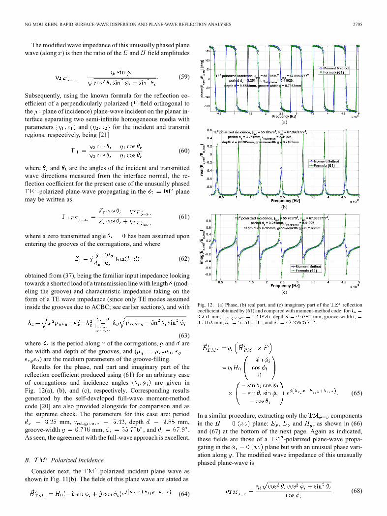
reflection coefficient produced using (61) for an arbitrary caseof corrugations and incidence angles are given inFig. 12(a), (b), and (c), respectively. Corresponding resultsgenerated by the self-developed full-wave moment-methodcode [20] are also provided alongside for comparison and asthe supreme check. The parameters for this case are: period
mm, , depth mm,groove-width mm, , and .As seen, the agreement with the full-wave approach is excellent.
B. Polarized Incidence
Consider next, the polarized incident plane wave asshown in Fig. 11(b). The fields of this plane wave are stated as
(64)
Fig. 12. (a) Phase, (b) real part, and (c) imaginary part of the reflectioncoefficient obtained by (61) and compared with moment-method code: for
mm, . depth mm, groove-widthmm, , and .
(65)
In a similar procedure, extracting only the componentsin the plane: , and , as shown in (66)and (67) at the bottom of the next page. Again as indicated,these fields are those of a -polarized plane-wave propa-gating in the plane but with an unusual phase vari-ation along . The modified wave impedance of this unusuallyphased plane-wave is
(68)

2706 IEEE TRANSACTIONS ON ANTENNAS AND PROPAGATION, VOL. 61, NO. 5, MAY 2013
Fig. 13. (a) Phase, (b) real part, and (c) imaginary part of the reflectioncoefficient obtained by (70) and compared with moment-method code: for
mm, . depth mm, groove-widthmm, , and .
Using this time the known formula for the reflection coefficientof a parallel-polarized plane-wave incident on the planar inter-face between two media, being [21]
(69)
and as before, assuming upon penetrating into thegrooves, we obtain
(70)
where is the same as that of (62), being still the same TEtype wave impedance and not the TM type wave impedanceas what one might wrongly imagine initially (since TM polar-ized incident plane wave is presently considered), because no
modes exist inside the grooves under ACBC (see earliersection).As before, results for the phase, real part and imaginary
part of the reflection coefficient produced using (70)for another arbitrary case of corrugations and incidenceangles are given in Fig. 13(a), (b), and (c), respec-tively. Corresponding results generated by the self-developedfull-wave moment-method code are also provided alongsidefor comparison and as the supreme check. The parametersfor this case are: period mm, ,depth mm, groove-width mm,
, and . Evidently, the agreementwith the full-wave approach is again seen to be superb.These direct analytic formulas of (61) and (70) for the
and complex reflection coefficients (not only the phase ormagnitude, but both) of planar corrugations provide speeds ofcharacterization as HIS and AMC surfaces that are higher thanmost full-wave solvers.
VII. CONCLUSION
An accurate but yet rapid method for analyzing surface-waveas well as reflection characteristics of planar corrugatedsurfaces is presented. Based on the use of asymptotic corru-gations boundary conditions (ACBC) which yield solutionsthat approach exactness as the period of the corrugations tendsasymptotically to zero, this method is able to treat not only theprincipal but also oblique azimuth planes of surface-wave prop-agation (for dispersion analysis) as well as of plane space-waveincidence and reflection (reflection analysis), for both TE andTM polarizations. In addition to the transcendental character-istic equation from which surface-wave dispersion properties(relating frequency to the surface-wavenumber) can be ac-quired, the formulation of this ACBC-based tool is also capableof producing explicit closed-form analytical expressions for the
(66)
(67)
NG MOU KEHN: RAPID SURFACE-WAVE DISPERSION AND PLANE-WAVE REFLECTION ANALYSES 2707
fields within both the groove region and the upper half-spaceabove the corrugations, being mathematical functions of all ge-ometrical and material parameters of the corrugated structure.These have potential to serve as facility for the modal analysisof such corrugated surfaces that coexist with other microwavedevices, such as mode-matching with waveguides, or evenfor the analysis of finite corrugations. Furthermore, these fieldexpressions also can find utility in the studies of surface-waveantennas made up of such planar gratings by permitting Fourierintegration of the radiating aperture.Moreover, not only is this ACBC method, for both TE
and TM polarizations, better in accuracy than the conven-tional transverse resonance technique (TRT), the latter alreadywell-reputed for offering quick and accurate insights intothe modal dispersion properties, it also provides speedup incomputation time as compared to CST Microwave Studio anda moment method code, with reduction in CPU clock timesby many thousand-folds, yet without compromising accuracy.This is on top of the fact that the ACBC technique holds upwell to full-wave solvers in terms of the ability to provide fieldexpressions, something which the TRT or other asymptoticmethods may not offer.By an unprecedented concept of atypical plane waves that
are unusually phased along a transverse direction when prop-agating within a principal plane, analytical expressions for thecomplex reflection coefficients of plane-waves impingent on thecorrugated surface were also derived for any general obliqueazimuth angle of plane-wave incidence, for both TE and TMpolarizations. These closed-form mathematical formulas, beingfunctions of all parameters of the corrugation structure as well asthe incident plane-wave (its direction and polarization), providevirtually instantaneous acquisition of the complex reflection co-efficient, both its real and imaginary parts.All in all, this proposed new treatment tool for planar corru-
gations offers improvements over both the classical TRT and thegenre of full-wave solvers, in terms of accuracy and the ability toyield field expressions compared with the former, while in termsof speed relative to the latter. It provides fast but yet accuratecharacterization of EBG structures, HIS/AMC surfaces, soft/hard surfaces, and surface-wave antennas composed of suchgratings, in terms of surface-wave dispersion and plane-wavereflection properties, as well as field distributions. This con-sequently affords likewise swift and effective designs of an-tennas and microwave devices that make use of such corrugatedsurfaces.
REFERENCES
[1] H. Goldstein, “Cavity resonators and waveguides containing periodicelements,” Ph.D. dissertation,Mass. Inst. of Technol., Cambridge,MA,USA, 1943.
[2] H. Goldstein, “The theory of corrugated transmission lines and waveg-uides,” MIT Radiation Lab, Rep. 494, Arp. 1944, pp. 1–17.
[3] G. Goubau, “Surface waves and their application to transmissionlines,” J. Appl. Phys., vol. 21, pp. 1119–1128, Nov. 1950.
[4] A. Sommerfeld, Ann. d. Physik, vol. 28, p. 665, 1909.[5] R. S. Elliott, “On the theory of corrugated plane surfaces,” IRE Trans.
Antennas Propag., pp. 71–81, Apr. 1954.[6] G. Piefke, “The transmission characteristics of a corrugated guide,”
IRE Trans. Antennas Propag., pp. 183–190, Dec. 1959.
[7] R. W. Hougardy and R. C. Hansen, “Scanning surface wave an-tennas—Oblique surface waves over a corrugated conductor,” IRETrans. Antennas Propag., pp. 370–376, Oct. 1958.
[8] H. A. Kalhor, “Numerical evaluation of Rayleigh hypothesis for an-alyzing scattering from corrugated gratings—TE polarization,” IEEETrans. Antennas Propag., vol. AP-24, no. 6, pp. 884–889, Nov. 1976.
[9] J. P. Kim, C.W. Lee, and H. Son, “Analysis of corrugated surface waveantenna using hybrid MOM/UTD technique,” IEE Elect. Lett., vol. 35,no. 5, pp. 353–354, Mar. 1999.
[10] E. Alfonso, A. Valero-Nogueira, J. I. Herranz, and F. Vico, “Mo-ment method analysis of corrugated surfaces using the apertureintegral equation,” IEEE Trans. Antennas Propag., vol. 57, no. 7, pp.2208–2212, Jul. 2009.
[11] P.-S. Kildal, “Artificially soft and hard surfaces in electromagnetics,”IEEE Trans. Antennas Propag., vol. 38, no. 10, pp. 1537–1544, Oct.1990.
[12] P.-S. Kildal, A. A. Kishk, and A. Tengs, “Reduction of forward scat-tering from cylindrical objects using hard surfaces,” IEEE Trans. An-tennas Propag., vol. 44, no. 11, pp. 1509–1520, Nov. 1996.
[13] Z. Ying and P.-S. Kildal, “Improvements of dipole, helix, spiral, mi-crostrip patch and aperture antennas with ground planes by using cor-rugated soft surfaces,” IEE Proc.Microw., Antennas, Propag., vol. 143,no. 3, pp. 244–248, Jun. 1996.
[14] T. B. A. Senior and J. L. Volakis, “Generalized impedance boundaryconditions in scattering,” Proc. IEEE, vol. 79, no. 10, pp. 1413–1420,Oct. 1991.
[15] T. B. A. Senior and J. L. Volakis, Approximate Boundary Conditions inElectromagnetics. Stevenage, U.K.: IET, “,” IET IEEE Electromag-netic Waves Series, 1995.
[16] H. A. Kalhor, “Approximate analysis of electromagnetic scatteringfrom corrugating conducting surfaces by surface impedance mod-eling,” IEEE Trans. Antennas Propag., vol. AP-25, pp. 721–722, Sep.1977.
[17] I. Hanninen and K. Nikoskinen, “Implementation of method of mo-ments for numerical analysis of corrugated surfaces with impedanceboundary condition,” IEEE Trans. Antennas Propag., vol. 56, no. 1,pp. 278–281, Jan. 2008.
[18] T. M. Uusitupa, “Usability studies on approximate corrugation modelsin scattering analysis,” IEEE Trans. Antennas Propag., vol. 54, no. 9,pp. 2486–2496, Sep. 2006.
[19] P.-S. Kildal, A. Kishk, and Z. Sipus, “Asymptotic boundary conditionsfor strip-loaded and corrugated surfaces,”Microw. Opt. Technol. Lett.,vol. 14, no. 2, pp. 99–101, Feb. 1997.
[20] M. Ng Mou Kehn, “Moment method analysis of plane-wave scatteringfrom planar corrugated surfaces using parallel-plate cavity Green’sfunctions and derivation of analytic reflection-phase formulas forboth polarizations and oblique azimuth planes,” Radio Sci., vol. 47, p.RS3008, Jun. 2012, 10.1029/2011RS004938.
[21] C. A. Balanis, Advanced Engineering Electromagnetics. New York,NY, USA: Wiley.
Malcolm Ng Mou Kehn (S’02–M’06) was born inSingapore on September 26, 1976. He received theB.Eng. (honors) degree from the National Universityof Singapore, Singapore, in 2001, and the Licentiateand Ph.D. degrees from Chalmers University ofTechnology, Gothenburg, Sweden, in 2004 and2005, respectively, all in electrical engineering.During 2006–2008, he was a Postdoctoral Fellow
in the Department of Electrical and Computer En-gineering, University of Manitoba, Winnipeg, MB,Canada. Following this, he proceeded to Concordia
University, Montreal, QC, Canada, for a year. In August 2009, he joined the De-partment of Electrical Engineering, National Chiao Tung University, Hsinchu,Taiwan, first as an Assistant Professor and then as an Associate Professor sinceAugust 2012. He had been actively involved in research projects funded by theSwedish Defense Research Agency between 2002 and 2006. During autumn2004, he spent several months at the University of Siena, Italy, for a researchvisit. In December 2004, he visited the University of Zagreb, Croatia, as aninvited speaker where he gave an IEEE lecture, in connection with the IEEECroatia Chapter activities. Throughout 2006 to 2009, he worked extensively onnumerous projects supported by Canadian industry and national research bodies.Since August 2009, he has been securing research project grants funded by theNational Science Council of Taiwan.Dr. Ng Mou Kehn received the Union Radio-Scientifique Internationale
(URSI) Young Scientist Award in 2007.