ieee transactions on automation science and …coejgyi/pdfs/tase2008.pdf · 2008-04-04 · ieee...
TRANSCRIPT

IEEE TRANSACTIONS ON AUTOMATION SCIENCE AND ENGINEERING, VOL. 5, NO. 2, APRIL 2008 321
Steady-State Throughput and Scheduling Analysis ofMulticluster Tools: A Decomposition Approach
Jingang Yi, Member, IEEE, Shengwei Ding, Dezhen Song, Member, IEEE, andMike Tao Zhang, Senior Member, IEEE
Abstract—Cluster tools are widely used as semiconductor manu-facturing equipment. While throughput analysis and scheduling ofsingle-cluster tools have been well-studied, research work on mul-ticluster tools is still at an early stage. In this paper, we analyzesteady-state throughput and scheduling of multicluster tools. Weconsider the case where all wafers follow the same visit flow withina multicluster tool. We propose a decomposition method that re-duces a multicluster tool problem to multiple independent single-cluster tool problems. We then apply the existing and extended re-sults of throughput and scheduling analysis for each single-clustertool. Computation of lower-bound cycle time (fundamental period)is presented. Optimality conditions and robot schedules that re-alize such lower-bound values are then provided using “pull” and“swap” strategies for single-blade and double-blade robots, respec-tively. For an -cluster tool, we present ( ) lower-bound cycletime computation and robot scheduling algorithms. The impact ofbuffer/process modules on throughput and robot schedules is alsostudied. A chemical vapor deposition tool is used as an example ofmulticluster tools to illustrate the decomposition method and algo-rithms. The numerical and experimental results demonstrate thatthe proposed decomposition approach provides a powerful methodto analyze the throughput and robot schedules of multicluster tools.
Note to Practitioners—Modeling and scheduling of cluster toolsare critical to improving the productivity and to enhancing the de-sign of wafer processing flows and equipment for semiconductormanufacturing. This paper presents a decomposition method tocalculate the maximum throughput and to analyze the robot actionschedule for a cluster tool that contains multiple transfer robots.The proposed algorithms utilize and extend the existing results forthe single-cluster tool that only has one transfer robot. Buffer mod-ules between two interconnected clusters are treated as either fic-titious cassette modules or fictitious process modules. Therefore,we can decompose the interconnected multicluster tool into mul-tiple single-cluster tools. The outcome of this research work pro-vides not only answers to possible maximum throughput for a givencluster tool system but also robot schedules that address how to
Manuscript received July 11, 2006; revised November 19, 2006. This paperwas recommended for publication by Associate Editor T. Lee and EditorN. Viswanadham upon evaluation of the reviewers’ comments. This paperwas presented in part at the 2005 IEEE International Conference on Roboticsand Automation, Barcelona, Spain, and in part at the 2007 IEEE InternationalConference on Robotics and Automation, Rome, Italy.
J. Yi is with the Department of Mechanical Engineering, San Diego StateUniversity, San Diego, CA 92182 USA (e-mail: [email protected]).
S. Ding is with the Department of Industrial Engineering and Operations Re-search, University of California at Berkeley, Berkeley, CA 94720 USA (e-mail:[email protected]).
D. Song is with the Department of Computer Science, Texas A&M Univer-sity, College Station, TX 77843 USA (e-mail: [email protected]).
M. T. Zhang was with AzFSM (Fab 12/22/32) Industrial Engineering, IntelCorporation, Chandler, AZ 85248 USA. He is now with Submicon DevelopmentCenter, Spansion Inc., Sunnyvale, CA 94088 USA (e-mail: [email protected]).
Color versions of one or more of the figures in this paper are available onlineat http://ieeexplore.ieee.org.
Digital Object Identifier 10.1109/TASE.2007.906678
reach such a maximum throughput. The scheduler can be imple-mented and run efficiently on the cluster tool computer of a generalconfiguration cluster tool. Comparing with rule-based and simula-tion-based scheduling methods, the benefits of the proposed analyt-ical approach include better throughput estimation, faster what-ifanalysis, and optimal scheduling solutions with varying processingtimes and cluster tool configurations. We have successfully testedthe methodology in this paper on dozens of cluster tools at IntelCorporation.
Index Terms—Cluster tool, decomposition, scheduling, semicon-ductor manufacturing, throughput.
NOMENCLATURE1
( ) The th cluster of an -cluster tool.
( ) Number of process modules (PMs) in ( ).
( ) Number of robot pick/place actions in ( ).
( ) Cassette module , , 2, in ( ).
Fictitious cassette module , , 2, in .
( ) Process module in ( ).
The th, , 2, buffer module betweenand .
: Collection of buffer modulesbetween and .The th, , 2, buffer/process modulebetween and .
: Collection of buffer/processmodules (BPM) between and .Wafer capacity of ( ).
( ) Robot in ( ).
( ) Robot ( ) type. if isdouble-blade and single-blade.Wafer visit route in the multicluster tool.
Wafer visit route in a decoupled .
The fundamental period of cluster tools.
The calculated fictitious fundamental period ofdecoupled .
( ) The time interval that ( ) picks/places awafer.
( ) Processing time at PM ( ).
Processing time at BPM , , 2.
( ) Robot ( ) cassette waiting time.
( ) Robot ( ) action schedule in ( ).
1Notations in parentheses are for the single-cluster tool case.
1545-5955/$25.00 © 2007 IEEE

322 IEEE TRANSACTIONS ON AUTOMATION SCIENCE AND ENGINEERING, VOL. 5, NO. 2, APRIL 2008
Fig. 1. A schematic of cluster tools [2]. (a) Single-cluster tool. (b) Two-clustertool.
I. INTRODUCTION
CLUSTER tools are widely used as semiconductor manu-facturing equipment. In general, a cluster tool is defined as
an integrated, environmentally isolated manufacturing systemconsisting of cassette, process, and transport modules mechan-ically linked together [1] [Fig. 1(a)]. Cassette modules (CMs)store the unprocessed and processed wafers. Process modules(PMs) execute semiconductor manufacturing processes, such aschemical vapor deposition (CVD), etching, and chemical-me-chanical planarization (CMP). Transfer modules (TMs), whichare robot manipulators, move wafers among process modulesand between process and cassette modules. For a single-clustertool, only one robot serves multiple process and cassette mod-ules [Fig. 1(a)]. A multicluster tool consists of several singleclusters that are interconnected through buffer modules (BMs)[Fig. 1(b)]. During a semiconductor manufacturing process,wafers are transported by robots from the cassette module, se-quentially go through various process modules, and then returnto the cassette module. Modeling, analysis, and scheduling ofcluster tools are critical to improve the productivity.
In this paper, we discuss modeling, analysis, and schedulingof a multicluster tool. We assume that all processing wafersfollow the same flow route. Our goal is to find an optimalschedule for TMs that minimizes cycle time and, therefore,maximizes throughput. We consider a general topologicalconnection among the multiple clusters and propose a methodto decompose the multicluster tool into multiple individualsingle-cluster tools. We then extend and apply the existingthroughput and scheduling analysis of the single-clustertool. For an -cluster tool, upper-bound maximumthroughput computation algorithms are presented. Optimalityconditions that could lead to such an upper-bound maximumthroughput are then provided and discussed. The impact ofcombined buffer/process modules (BPMs) on throughput andscheduling of cluster tools is also discussed. A CVD tool isused as an example of the multicluster tools to illustrate theproposed decomposition methods and algorithms.
The contributions of this paper are twofold. First, we formu-late a multicluster scheduling and analysis problem, and pro-pose an analytical solution to such a problem using a decompo-sition method. To our knowledge, there is no research work thatformally discusses the maximum throughput calculation andscheduling analysis for a general multicluster tool. The researchwork presented in this paper not only provides the upper-boundmaximum throughput for a given cluster tool system but alsodiscusses optimality conditions and robot schedules to realizesuch a throughput. Second, using the decomposition approach,the proposed algorithms can help practitioners (such as clustertool design engineers and process development engineers) tocompute and predict the maximum cluster tool throughput. Thealgorithms can also help identify the process flow bottlenecks,and quickly search for an optimal robot schedule that minimizesthe cycle time. The proposed methods and algorithms can beimplemented on cluster tool computer (CTC) and be utilized inpractice for wafer production. We have successfully applied theproposed methodology in this paper to dozens of cluster toolsat Intel Corporation.
The remainder of this paper is organized as follows. Webegin with related work in Section II and discuss the structureof the multicluster tools in Section III. In Section IV, wediscuss and extend optimal schedules for single-cluster tools.Section V presents a decomposition method for multiclustertools and the algorithms to compute the lower-bound of theminimal cycle time (or so-called fundamental period). Opti-mality conditions under which the lower-bound fundamentalperiod can be achieved and the robot scheduling algorithmare also presented in this section. In Section VI, we apply andextend decomposition results to analyze BPMs. An exampleof throughput analysis and robot scheduling is investigatedfor a CVD tool in Section VII. Finally, we summarize withconcluding remarks and future research directions.
II. RELATED WORK
For cluster tools, robot moving and wafer processing se-quences repeat cyclically at steady state. Like most literatures,we consider the cycle time for a one-wafer action sequenceas the optimization objective. A one-wafer action sequence isdefined as a sequence of robot actions which pick and placeeach module exactly once [3].

YI et al.: STEADY-STATE THROUGHPUT AND SCHEDULING ANALYSIS OF MULTICLUSTER TOOLS 323
The multicluster tool scheduling problem cannot be simplyviewed as a special case of flow-shop scheduling problem orjob-shop scheduling problem [4] with deterministic processingand interarrival times. In fact, it is a tight mixed of the two,which makes the problem challenging. The extreme cases of amulticluster tool scheduling problem can be reduced to eithercase depending on viewpoints. For example, if observing thesystem from transfer module (robot) viewpoint and assumingthe zero processing time for each process module, the multi-cluster tool is now a typical job shop with the robot as the work-station and each pick/place action as the job. Therefore, thescheduling problem is reduced to a typical job shop schedulingproblem. If observing the system from wafer viewpoint and as-suming the zero wafer pick and place action time, the multi-cluster tool now behaves like a typical flow shop. Each processmodule can be viewed as individual workstations and there is nobuffer in-between workstations. Then, the scheduling reduces toa typical workshop scheduling problem. However, since the pro-cessing times are nonzero and the flow between adjacent work-stations depends on the availability of robots, the job shop orwork shop scheduling results cannot be directly applied to theregular multicluster tool scheduling problem.
In [5] and [6], analytical models of steady-state throughputare discussed for a cluster tool equipped with single-blade anddouble-blade robots, respectively. A single-blade robot usuallycan hold only one wafer at a time. A double-blade robot hastwo independent arms and, therefore, can hold two wafers at thesame time with one on each arm.2 For a cluster tool with a single-blade robot, Perkinson et al. [5] propose a “pull” (or so-calleddownhill) optimal schedule strategy for the robot moving se-quence. For a double-blade robot, Venkatesh et al. [6] proposethe optimal schedule by a “swap” action. Results in [7] and [8]imply that the pull strategy for single-blade cluster tool is anoptimal schedule. The results presented in [9] for double-griprobotic cells can be applied to a double-blade robot cluster tooland show that the swap schedule is one of the optimal strategies.In [10]–[12], scheduling analysis of one robot flow shop is alsodiscussed for the single- and double-gripper robots in a buffer-less environment. Recently, Dawande et al. [3] summarized thesequencing and scheduling in robotic cells, which is similar tocluster tools.
Petri nets have been used to model the semiconductor manu-facturing systems [13]. To model the cluster tool process flows,Srinivasan [14], Zuberek [15], and Wu and Zhou [16] use Petrinets to study the performance of the cluster tool processes for agiven robot scheduling strategy. For a cluster tool with multipleprocess modules and transfer robots, Petri nets modeling, sched-uling, and analysis can become complicated. Rostami et al. [17]and Rostami and Hamidzadeh [18] have used linear program-ming and heuristic methods to study the optimal schedules fora single-cluster tool with residency constraints on transfer andprocess modules. Simulation of cluster tools also plays an im-portant role in studying the throughput and in optimizing theprocess and design, for example, cluster tool physical layoutsimulation [19]–[21] and event graph modeling and simulationof cluster tools [22]–[24].
2Most robots used in the semiconductor manufacturing industry have eitherone blade or two blades.
Most aforementioned work discuss the steady-statethroughput and robot scheduling analysis with an identicalwafer flow. Perkinson et al. [25] present the impact of parallel(redundant) process modules and revisiting wafer flows onsteady-state throughput. Geismar et al. [26] extend the resultin [25] and discuss the throughput and scheduling analysis ofa robotic cell with a single-gripper robot and parallel stations.Herrmann et al. [27] study the impact of processing time vari-ations on steady-state throughput and robot scheduling usingnetwork flow and simulation models for some simple clustertools. Ding et al. [28] extend the network model in [27] to amulticluster tool.
All of the work above discusses the single-cluster tool con-figuration except simulation study in [24] and [28]. The single-cluster tool scheduling is relatively straightforward. Withthe increasing complexity of semiconductor manufacturingprocesses, multicluster tools are needed to accommodate theindustry needs. For a multicluster tool [such as the one shown inFig. 1(b)], wafer flow modeling and scheduling are apparentlymore complicated than those of a single-cluster tool becausemultiple robots can move and transfer wafers simultaneouslyand coordinately.
Recently, Geismar et al. [29] discussed a robotic cell withthree single-gripper robots for semiconductor manufacturingwith identical robot pick/place time. They present a lower-boundfor the cycle time for a robotic cell with parallel machines andmultiple robots in a bufferless environment. The authors alsocompare the throughput of the pull strategy [5] for each robotwithin the cell with a “longest waiting pair” (LWP) strategythat is employed by the manufacturer. Their simulation studyshows that for most cases (87%) the pull strategy achieves thelower-bound performance and improves the throughput signifi-cantly. In Ding et al. [28], an integrated event graph and networkmodel is used to find all optimal schedules for a multicluster toolthat can achieve the minimum cycle time. Sensitivity analysis ofthe processing time variation on the entire tool’s throughput isalso discussed in [28]. A robust robot sequencing and schedulingcould be found if there exist several optimal schedules under thenominal processing time that could lead to the same throughput.In [2] and [30], several rule or priority based heuristic schedulingmethods of robot actions of multicluster tools have been dis-cussed. However, there are few analysis and comparison studiesof those heuristic methods in terms of optimality.
This paper extends the results in Yi et al. [31] and Yi et al.[32], and we discuss the optimal schedules only based on pulland swap robot strategies. We find the optimality conditionsunder which the pull and swap robot strategies can achieve theminimum cycle time. Pull and swap strategies are of our inter-ests because they are simple and easily implemented in clustertools [5]–[8], [10], [11], [29]. The main goal of this study is toanalytically investigate the throughput and scheduling of mul-ticluster tools with a general configuration. The general multi-cluster tool configuration covers all reported cluster tools in ex-isting work. Even for some cluster tools that do not seeminglylook like clustered modules in physical layout, such as the CMPpolisher in [22] and [26], we can still apply our results to thesetools by abstracting the layout into an -cluster tool discussedin this paper.

324 IEEE TRANSACTIONS ON AUTOMATION SCIENCE AND ENGINEERING, VOL. 5, NO. 2, APRIL 2008
Fig. 2. A schematic of an interconnectedM -cluster tool.
III. PROBLEM DESCRIPTION
A. Cluster Tool Assumptions
We consider an interconnected -cluster tool shown inFig. 2. For robot action and each PM processing time, we havethe following assumptions.
Assumption 1: Processing time assumptions.1) Robot takes the same amount of time to pick and
place a wafer.2) Robot spends zero time to travel to next module (either
PM or CM).3) Robot transfer time and PM processing time are de-
terministic.Assumption 1.2 of zero traveling time among different
process modules is reasonable for practical systems since PMsare normally arranged in a circular layout around robot andit, therefore, takes a negligible time for to travel from onePM to another PM. Although in this paper we mainly considerthe cases where the robot transferring time is constrained byAssumption 1.1, similar results can be obtained for the caseswhere robot spends different time intervals to pick and placea wafer.
We also make the following assumptions for the -clustertool.
Assumption 2: Multicluster tool assumptions.1) All wafers follow the identical visit flow and this wafer
flow visits each PM only once.3
2) CMs always have wafers/spaces for robot to pick or placeat any time.
3) Each robot is either single-bladed or double-bladed.4) Buffer module has either one- or two-wafer capacity,
and if has two wafer capacity, one is used for waferoutlet direction (relative to ) and another is for waferinlet direction.
5) Each cluster must connect to at least one but at most twoother clusters.
6) The multiple clusters cannot form a loop interconnection.Remark 1: It is noted that in fab production, Assumptions
2.1 is reasonable since a large amount of wafers are processedfollowing the same recipe at one cluster tool. Also, we do notconsider the cases where one wafer skips one PM or is processedtwice at the same PM (i.e., reentry process flow). Assumption
3We consider multiple parallel process modules as one PM in this assumption.
2.2 is also reasonable since there are multiple front opening uni-fied pods (FOUPs) available at each cluster tools for continu-ously wafer loading/unloading.
For the -cluster tool shown in Fig. 2, we have the followingdefinitions.
Definition 1: A BM , , 2, between andis called buffer/process module (BPM) if it also functions as aprocess module with processing time .
It is clear that a regular BM can be considered as a BPMwith zero processing time. Due to the complexity introducedby BPM, we separate the BPM discussion in Section VI to keepthe presentation clarity. We will first focus on multicluster toolsinterconnected by BMs. Then, we treat BPMs as an extensionof the proposed methodology.
Definition 2: A cluster is called transfer cluster if:1) is a single-blade robot.2) There is no process module, i.e., .3) Both sides of the BMs have one-wafer capacity, i.e.,
and .For a transfer cluster, there are not enough wafer storage space toflexibly move wafers within the cluster. We will handle transferclusters slightly different from regular clusters.
B. Cyclic Wafer Processing
If wafers follow the same visit route within the cluster tool,the production follows the cyclic production pattern in whichwafers are driven by a fixed sequence of robot actions. Forthe -cluster tool, we define that the robot action isan atomic pick or place motion, where , and
is the total number of robot actions. We can decomposeany robot actions into a combination of several such basicatomic motions. For example, after a single-blade robot picks awafer, a robot place action must be followed. Such a pick/placemovement consists of two basic robot actions in sequence. Fora double-blade robot, such a constrained movement however isnot necessary since a double-blade robot could use one bladeto hold a wafer and use the other blade to pick another waferbefore placing the wafer on the first blade. Furthermore, fora tighter schedule, it is appropriately assumed that the waferprocessing at each PM starts right after the robot places anunprocessed wafer inside that module. Therefore, we can onlyconsider the sequencing and scheduling of robot actions andonce such a schedule is fixed the entire cluster tool’s activities

YI et al.: STEADY-STATE THROUGHPUT AND SCHEDULING ANALYSIS OF MULTICLUSTER TOOLS 325
are determined. We define a one-wafer cycle production asfollows [3].
Definition 3: A one-wafer cycle is the performance of afeasible one-wafer action sequence that leaves the cluster toolin exactly the same state as its state at the beginning of thoseactions.
We can denote the robot schedule as a doublet of itsactions and their relative starting times in one cycle:
, . We define the functionas the time of completion of the th cycle
execution [7]. The long-run average throughput or simply,throughput can be defined as [7]
(1)
We also take the following definitions from Crama andvan de Klundert [7] for steady state and cycle time forone-wafer cycle .
Definition 4: A cluster tool repeatedly executing a one-wafercycle of robot actions is operating in steady state if there exista constant and a constant such that ,
, and , ,. is called the cycle time of .
We define the optimal schedules as the set of any one-wafercycle under which the throughput of the cluster tool is max-imized. It is observed that if an optimal schedule maximizesthe throughput , it must minimize the cycle time , i.e.,
. In this paper, we adopt the terminology“fundamental period” in the literature for the minimal one-wafercycle time [5], [6].
Definition 5: A fundamental period of a cluster tool isdefined as the minimal one-wafer cycle time , i.e.,
.
It is obvious that if a cluster tool has a fundamentalperiod , then the maximum steady-state throughput is
.
C. Problem Definition
The objective of this study is to provide a methodology toanalyze throughput and robot scheduling of multicluster toolsunder identical wafer visit routes. For the -cluster tool underAssumptions 1 and 2, our goal is to address the followingquestions.
1) What is the steady-state lower-bound fundamental period( ) (or maximum throughput) of a multicluster tool?
2) What are the optimality conditions and robot schedules fora cluster tool to reach such a minimum cycle time?
IV. SINGLE-CLUSTER TOOL OPTIMAL SCHEDULE
In this section, we first review the existing analysis of sched-uling for a single-cluster tool, and then extend these results forthe proposed decomposition method in the next section.
A. Maximal Cassette Waiting Time Strategy
Depending on processing time , , and transfertime , a single-cluster tool could be running in two possible re-gions: process-bound and transfer-bound regions [5], [6]. When
Fig. 3. Gantt chart of maximal cassette waiting time strategies for the exampletool shown in Fig. 1(a) that runs in a process-bound (arrows represent robotaction durations and rectangle bars represent PM processing durations). (a) Pullstrategy for single-blade robot R. (b) Swap strategy for double-blade robot R.
the cluster is in a process-bound region, the largest processingtime dominates and the robot has some idle time. In thetransfer-bound region, processing time is relatively small andthe robot is always busy in transferring wafers.
According to [5] and [8], for a single-cluster tool that hasPMs [ for the example shown in Fig. 1(a)], one optimalschedule is given by the following pull robot movements: robotfirst picks up the wafer in (assuming there is one processedwafer in each PM) and places into , and keeps moving wafersfrom to , , until picking up a waferfrom cassette and places it into . Finally, robot waits at
to start the next cycle. Fig. 3(a) shows the robot movingsequences and processing sequences for the example cluster toolshown in Fig. 1(a) with a single-blade robot.
For a double-blade robot cluster tool, optimal scheduling isdifferent due to the swap actions that two-blade robot can carryout [6], [10]. Fig. 3(b) shows the robot movment and processingsequences for the cluster tool given in Fig. 1(a) with a double-blade robot. The swap strategy works as follows: the robot firstpicks an unprocessed wafer from (on blade 1), moves it to
, picks up the processed wafer in (on blade 2), and placesthe wafer (on blade 1) into (swap action). It then moves towith the wafer from on blade 2 and start another swap action.The robot keeps swapping wafers through , ,and finally takes the processed wafer from to the cassette.
Denote the maximum and minimum processing times ofprocess modules as and , respectively
(2)
326 IEEE TRANSACTIONS ON AUTOMATION SCIENCE AND ENGINEERING, VOL. 5, NO. 2, APRIL 2008
Based on the optimal schedule described above, the funda-mental period (for a single-blade cluster tool) and(for a double-blade cluster tool) can be calculated in a form
ifif
(3)
ifif
(4)
The first subequation in (3) and (4) represents the case when thetool is running in the transfer-bound region and the second inthe process-bound region.
If we consider the cassette module functions as a processmodule with zero processing time, i.e., , then we canrewrite (3) and (4) in a compact form that will be used later
(5)
where if is double-blade and if is single-blade.When the robot schedule discussed above is applied to one
of the clusters within a multicluster tool, it is important to ana-lyze the robot waiting time at the interconnected BMs betweentwo adjacent clusters because any waiting time at the BM couldresult in a delay in one cluster and such a delay could propa-gate further to other clusters. Equivalently, we need to considerhow to allocate the robot idle time (or waiting time) at the cas-sette modules since for a multicluster tool the BM functions asa cassette module. We define the robot cassette waiting time asfollows.
Definition 6: The robot cassette waiting time is definedas the time lag of robot between the moments when finishingthe action “pick an unprocessed wafer from input cassette” andstarting the subsequent action “place a processed wafer intooutput cassette.”
It is noted that in the single-blade robot schedule discussedabove, after the robot moves an unprocessed wafer from cassette
to , robot may wait for an idle time [shownin Fig. 3(a)] at cassette for the next cycle even though theprocessed wafer in is ready for pickup. Let denote thetotal robot idle time. Then
(6)
and
(7)
The double-blade robot also waits at cassette module betweenpick and place actions at the cassette module [Fig. 3(b)], i.e.,
. Therefore, the robot schedule is a maximal cassettewaiting time strategy.
In contrast of the maximal cassette waiting time strategy dis-cussed above, we can find alternative pull and swap strategiesto minimize the robot cassette waiting time.
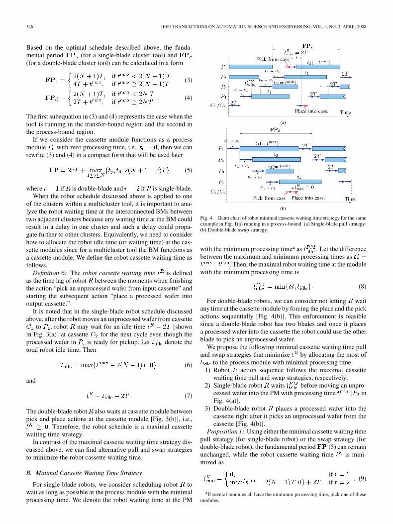
B. Minimal Cassette Waiting Time Strategy
For single-blade robots, we consider scheduling robot towait as long as possible at the process module with the minimalprocessing time. We denote the robot waiting time at the PM
Fig. 4. Gantt chart of robot minimal cassette waiting time strategy for the sameexample in Fig. 1(a) running in a process-bound. (a) Single-blade pull strategy.(b) Double-blade swap strategy.
with the minimum processing time4 as . Let the differencebetween the maximum and minimum processing times as
. Then, the maximal robot waiting time at the modulewith the minimum processing time is
(8)
For double-blade robots, we can consider not letting waitany time at the cassette module by forcing the place and the pickactions sequentially [Fig. 4(b)]. This enforcement is feasiblesince a double-blade robot has two blades and once it placesa processed wafer into the cassette the robot could use the otherblade to pick an unprocessed wafer.
We propose the following minimal cassette waiting time pulland swap strategies that minimize by allocating the most of
to the process module with minimal processing time.1) Robot action sequence follows the maximal cassette
waiting time pull and swap strategies, respectively.2) Single-blade robot waits before moving an unpro-
cessed wafer into the PM with processing time [ inFig. 4(a)].
3) Double-blade robot places a processed wafer into thecassette right after it picks an unprocessed wafer from thecassette [Fig. 4(b)].
Proposition 1: Using either the minimal cassette waiting timepull strategy (for single-blade robot) or the swap strategy (fordouble-blade robot), the fundamental period (5) can remainunchanged, while the robot cassette waiting time is mini-mized as
ifif
(9)
4If several modules all have the minimum processing time, pick one of thesemodules.
YI et al.: STEADY-STATE THROUGHPUT AND SCHEDULING ANALYSIS OF MULTICLUSTER TOOLS 327
Proof: See Appendix A.Without confusion, we will abuse notation to denote
in the rest of this paper unless explicitly indicated.
C. Parallel Process Modules
It is common that there may exist several identically parallelprocess modules in cluster tools which perform exactly the samefunctionality. The use of the parallel process modules can pre-vent or reduce production downtime and increase productivitysince wafers only need to go through one of parallel processmodules.
We consider a single-cluster tool with process steps. Wedenote as the redundancy level, i.e., number of parallel mod-ules for process , . If has only one PM, then
, namely, no parallel PM. Define the least common mul-tiple (LCM) of as , i.e., . It has beenshown in [26] that a pull schedule can still achieve the maximumthroughput for a single-blade robot under a set of feasible condi-tions.Wecaneasilyobtainsimilar results foradouble-bladerobotcase. Therefore, we can extend the fundamental period calcula-tion in (5) for a single-cluster tool with parallel modules as
(10)
For parallel PM cluster tools, the robot action repeats for each-wafer cycle.
V. OPTIMAL SCHEDULING OF MULTICLUSTER TOOLS
USING A DECOMPOSITION METHOD
A. Cluster Decomposition Concept
To analyze multicluster systems, we propose an approach todecouple the interconnection among clusters, and then apply thesteady-state performance and scheduling results to each decou-pled single-cluster tool.
The key of the approach is to decouple the link between clus-ters. As shown in Fig. 2, for in a multicluster system, weknow that wafers flow in or out of the cluster through either BMsor cassette modules. exchanges wafers with through
, . plays dual roles: for , acts like a fic-titious cassette module; for , on the other hand, it acts likea fictitious process module.
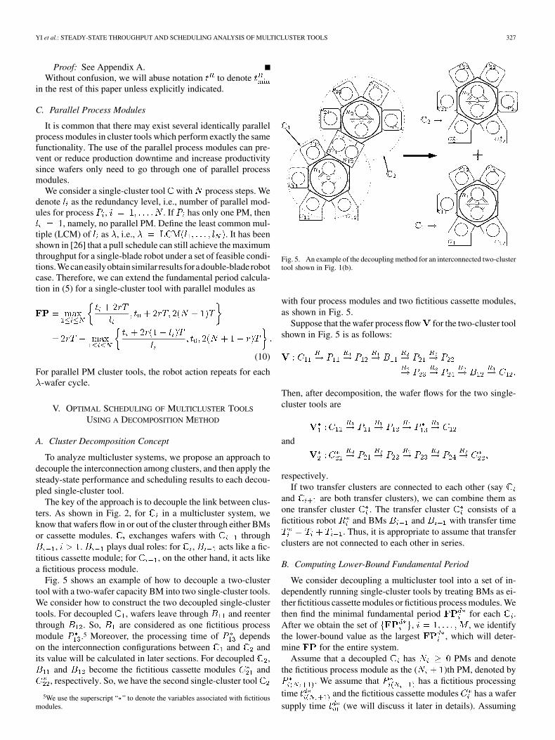
Fig. 5 shows an example of how to decouple a two-clustertool with a two-wafer capacity BM into two single-cluster tools.We consider how to construct the two decoupled single-clustertools. For decoupled , wafers leave through and reenterthrough . So, are considered as one fictitious processmodule .5 Moreover, the processing time of dependson the interconnection configurations between and andits value will be calculated in later sections. For decoupled ,
and become the fictitious cassette modules and, respectively. So, we have the second single-cluster tool
5We use the superscript “�” to denote the variables associated with fictitiousmodules.
Fig. 5. An example of the decoupling method for an interconnected two-clustertool shown in Fig. 1(b).
with four process modules and two fictitious cassette modules,as shown in Fig. 5.
Suppose that the wafer process flow for the two-cluster toolshown in Fig. 5 is as follows:
Then, after decomposition, the wafer flows for the two single-cluster tools are
and
respectively.If two transfer clusters are connected to each other (say
and are both transfer clusters), we can combine them asone transfer cluster . The transfer cluster consists of afictitious robot and BMs and with transfer time
. Thus, it is appropriate to assume that transferclusters are not connected to each other in series.
B. Computing Lower-Bound Fundamental Period
We consider decoupling a multicluster tool into a set of in-dependently running single-cluster tools by treating BMs as ei-ther fictitious cassette modules or fictitious process modules. Wethen find the minimal fundamental period for each .After we obtain the set of , , we identifythe lower-bound value as the largest , which will deter-mine for the entire system.
Assume that a decoupled has PMs and denotethe fictitious process module as the ( )th PM, denoted by
. We assume that has a fictitious processingtime and the fictitious cassette modules has a wafersupply time (we will discuss it later in details). Assuming

328 IEEE TRANSACTIONS ON AUTOMATION SCIENCE AND ENGINEERING, VOL. 5, NO. 2, APRIL 2008
that and are known, , from (5),
we can obtain as follows:
if is a transfer cluster
otherwise(11)
where
In (11), we have to separate the case when is a transfer clusterwhere the fundamental period calculation is different. For ,there is no fictitious PM and we can, therefore, ignore in thecalculation of .
Let us now discuss how to compute and .Fictitious cassette ’s supply time can be considered as
the minimum loading delay time of . Robot cannot picka wafer from the fictitious cassette module before robot fin-ishes loading the wafer. This incurs a loading delay . For ex-ample, if both and are double-blade robots, swap ac-tion is considered as the most efficient moving sequence of adouble-blade robot since there is no time gap between pickingand placing actions, thus in this case. We consider theloading delay as how long it takes to refill afterplaces a wafer into . has a processing time(assuming this value is non-negative) because it will take at least
between the moment placing a wafer intoand the moment placing a unprocessed wafer for pickup.Therefore, we can obtain , , for a general case as
(12)
For cluster , we have due to the fact that alwayshas real cassette modules with wafers/spaces inside.
The value of depends on the minimal loading timedelay at . The minimal loading delay time can be ob-tained in the same way as we discussed above for with ad-ditional consideration for minimal robot cassette waiting time
of . Therefore, we can calculate as
(13)
With the analysis above, the computation of for the mul-ticluster tools can be described as in Algorithm 1.
Algorithm 1: Decoupled calculation of a cluster tool.
Input : Cluster tool configuration and wafer flow
Output : Lower-bound fundamental period for
Decompose the tool into single-cluster tools;
Construct the wafer flows , , for each .
for to 1 do
Construct by (12) and by (13).
Calculate for cluster using (11).
end
}.
C. Optimality Conditions of Lower-Bound FundamentalPeriod
The lower-bound fundamental period computed in theprevious section might not be realized for all types of multi-cluster tool configurations due to the fact that we use a minimaltime interaction between two adjacent clusters in the compu-tations. Therefore, it is natural to ask what are the optimalityconditions under which the computed is feasible and howto find an optimal robot schedule under these conditions.
Proposition 2: For an -cluster tool, the computed funda-mental period by Algorithm 1 is feasible if for each cluster
, , the minimal robot cassette waiting time satisfiesthe following condition:
ifif
(14)
Proof: See Appendix B.Remark 2: Optimality conditions in Proposition 2 are suffi-
cient but not necessary. However, for most cluster tools in prac-tice, these optimal conditions are easily satisfied since double-blade robots are widely used in practice (such as the CVD toolthat we will discuss in Section VII).
D. Robot Scheduling
In this section, we provide a scheduling algorithm for the mul-ticluster tool that could reach by Algorithm 1. We use a “nowaiting” schedule that has been implemented in practice: oncethe wafer has been placed into the process module, the processstarts right away. For such a schedule, each process starting timeis completely dependent on the robot action starting time. Forrobot and decoupled , we denote its schedule as . Aftera proper timing shift of ’s by interconnection relationships,they can be fitted into a multicluster schedule with the fun-damental period . The feasibility of the optimal schedule bythis timing shift is guaranteed by the optimality conditions dis-cussed in the previous section.
The decomposed cluster schedule is chosen as follows.1) If is a single-blade cluster, time zero in starts at the
moment when robot takes a processed wafer from thelast process module (followed by the action of placing thesame wafer into the fictitious cassette module ). Allother robot actions follow the minimal cassette waitingtime pull strategy. The last action is to take an unprocessedwafer from . If the last action finishes before , therobot keeps idle until .
2) If is a double-blade cluster, the time zero robot actionis the moment when picks an unprocessed wafer from
(followed by the action of placing a processed waferinto ). All other robot actions follow the swap strategy.The last action is to place a wafer into the last (fictitious)process module ( ). If the last action finishesbefore , the robot keeps idle until .
3) If is a transfer cluster, the time zero robot action is themoment when picks a processed wafer from (fol-lowed by the action of placing the same wafer into ).Robot then waits for to be ready for next unpro-cessed wafer. Finally, it picks the wafer from and placesit into . If the last action finishes before , the robotkeeps idle until .

YI et al.: STEADY-STATE THROUGHPUT AND SCHEDULING ANALYSIS OF MULTICLUSTER TOOLS 329
Algorithm 2: A “no-wait” optimal robot scheduling.
Input : Cluster tool configuration, wafer flow , andfundamental period
Output: Scheduling for
Obtain the decomposed schedule ,, for cluster , , using (a) swap
strategy ( ) or (b) the minimal cassette waiting time pullstrategy ( ).
Initialize system schedule as .
for to do
Search for that picks wafers from
. Mark starting time as .
.
for to do
Update .
end
.
end
Algorithm 2 describes an optimal robot schedule as discussedabove. In Algorithm 2, denotes the number of robot ac-tions of decoupled . This algorithm leads to a unique sched-uling solution by forcing all robot movements to be started aslate as possible up to when the previous cluster wants to take thewafer from the BM. It is also noted that since the decomposedschedules are extended to , all process modules can befitted into the gaps between robot actions in the schedule.
VI. BUFFER/PROCESS MODULES (BPM)
The use of BPMs can make the cluster tool more compact andsave the tool’s footprint and cost. The existence of BPMs could,however, affect the throughput and the robot schedule becauseits dual role as a process module could introduce a significantcomplexity in analysis.
A. Fundamental Period Computation With BPMs
We consider that there is a BPM between and ,(Fig. 6). has either one- or two-wafer
capacity. We denote the incoming BPM (wafer flow fromto ) as and outgoing BPM (wafer flow fromto ) as , respectively. If has one-wafer capacity,
, then and share the same physical buffer de-vice. If has two-wafer capacity, , andare independent buffer devices. For presentation simplicity, we
Fig. 6. A combined BPM with two-wafer capacity.
use Fig. 6 to represent both cases. Let and be the pro-cessing time of and , respectively.
For presentation convenience, we introduce followingnotations:
(15)
where is the minimal robot cassette waiting time for the de-coupled cluster .
We first compute the fundamental period by the decomposi-tion algorithm in Section V assuming that there were no BPMwithin the cluster tool, namely, . We denotesuch a calculation as . Depending on the BPM wafer ca-pacity and processing time , , we can obtain the fol-lowing results.
Proposition 3: For an -cluster tool with a BPM be-tween clusters and , the fundamental period of thecluster tool can be calculated as follows.
• If , see (16) shown at the bottom of the page.• If
if
if
if(17)
where - are defined as (19a)–(19g)6 (and graphicallyshown in the - plane in Fig. 7)
(19a)
6 is defined as the set of non-negative real numbers, i.e., = fx 2j x � 0g.
ifotherwise
(16)

330 IEEE TRANSACTIONS ON AUTOMATION SCIENCE AND ENGINEERING, VOL. 5, NO. 2, APRIL 2008
Fig. 7. FP calculation for different BPM process time t and t distribu-tions if S = 2.
(19b)
(19c)
(19d)
(19e)
(19f)
(19g)
Moreover, the pull strategy for single-blade robots and swapstrategy for double-blade robots can be used to achieve cal-culated above.
Proof: See Appendix C.Remark 3: It is interesting to point out that transfer cluster
could be considered as a special one-wafer capacity BPMwith processing time . Therefore, from(28), we can obtain the requirement for a feasible transfer clusterschedule as
Remark 4: It is noted that when the long BPM processingtime dominates , there could exist some robot schedulesthat result in a smaller (average) fundamental period than thosevalues calculated by (16) and (17). This is due to the fact that thenon one-wafer cycle schedule could generate a smaller averagecycle time. We can guarantee that the calculated by the firstcase in (16) and first two cases in (17) is the minimal one-wafercycle time. However, for the second case in (16) and third case in(17), it is guaranteed that these values are the minimal one-wafercycle times for pull and swap strategies. Discussion of the nonone-wafer cycle production is out of the scope of this paper andreaders can refer to Geismar et al. [33].
The BPM analysis can be integrated into the fundamental pe-riod computation algorithms discussed in the previous section.Suppose that there exist BPMs within the -cluster tool,where , and we denote the BPM indexing set as
. We can calculate the fundamental period of the cluster toolwith BPMs based on Proposition 3. Algorithm 3 describes sucha modified fundamental period calculation.
Algorithm 3 : calculation of a cluster tool with BPMs.
Input : Cluster tool configuration and wafer flow
Output: Fundamental period for
Calculate assuming , , , 2 byAlgorithm 1.
for do
Calculate for each BPM using (16) or (17).
end
.
B. Robot Scheduling With BPMs
For robot scheduling with BPMs, we use the method that isdescribed in Algorithm 2. We can incorporate the discussion inAppendix C into Algorithm 2. It is proper to schedule in the waysuch that process ends right before action “ pickingwafer from ” starts, and process starts right afteraction “ placing wafer into ” ends. Then, in Algorithm2, we can modify the following calculation for BPMs:
(20)
VII. EXPERIMENTAL EXAMPLES
We have successfully applied the methodology described inthis paper to dozens of tools at Intel Corporation. The bene-fits include better throughput estimation, faster what-if analysis,and optimal scheduling solutions. Due to the page limit, wecannot discuss these advantages in details. In this section, weonly demonstrate one example to show how to apply the pro-posed methodology in semiconductor manufacturing practice.
A. ALD/CVD Cluster Tool
Thin-film tools are widely used in semiconductor manufac-turing to deposit metals onto silicon wafer surface using ei-

YI et al.: STEADY-STATE THROUGHPUT AND SCHEDULING ANALYSIS OF MULTICLUSTER TOOLS 331
Fig. 8. A schematic layout of a CVD cluster tool.
ther CVD, physical vapor deposition (PVD), sputter, atomiclayer deposition (ALD), or electroplate processes. Fig. 8 showsa layout of an ALD/CVD cluster tool.7 This is a two-cluster tool.The service cluster includes a double-blade robot , cas-sette and , and four process modules (chambers): par-allel process modules and , and parallel process modules
and . As discussed in Section IV-C, and , andand perform the same function, respectively. The pro-
cessing cluster includes a double-blade robot and threeprocess modules (chambers). Two of these three process mod-ules, and , are parallel modules. The interconnectionBMs between and are and . All processingwafers on this cluster tool follow the visit route (the split arrowsindicate the flow at parallel PMs):
The processing time and robot transfer time for the CVDcluster tool are listed in Table I.
B. Maximum Throughput and Robot Schedule Results
The CVD cluster tool can be decomposed into two single-clusters, and , as shown in Fig. 8. We can directly apply
7Detailed information about such a type of cluster tool can be found at http://www.amat.com/products.
TABLE IPROCESS AND TRANSFER TIME OF THE CVD CLUSTER TOOL
TABLE IICOMPUTATIONAL RESULTS FOR THE CVD CLUSTER TOOL BY ALGORITHM 1
(“D” FOR DOUBLE-BLADE; “S” FOR SINGLE-BLADE)
the decomposition technique discussed in Section V to this two-cluster tool.
Table II illustrates the maximum throughput calculationfor the CVD cluster tool using the decoupled single-clusterapproach (Algorithm 1). Here, we have to use (10) for parallelprocess modules in both clusters and . For , theredundancy level is , and from (10)–(11) andTable I, we have
(21)
Similarly, for , we have
(22)
We then can calculate the fundamental period assumingzero BPM processing times. Using Algorithm 1, we can calcu-late the of the two-cluster CVD cluster tool as
For BPMs and , we can find that
(23)
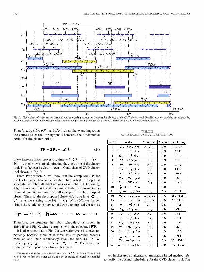
332 IEEE TRANSACTIONS ON AUTOMATION SCIENCE AND ENGINEERING, VOL. 5, NO. 2, APRIL 2008
Fig. 9. Gantt chart of robot action (arrows) and processing sequences (rectangular blocks) of the CVD cluster tool. Parallel process modules are marked bydifferent patterns with their corresponding symbols and processing time (in the brackets). BPMs are marked by dark colored blocks.
Therefore, by (17), and do not have any impact onthe entire cluster tool throughput. Therefore, the fundamentalperiod for the cluster tool is
(24)
If we increase BPM processing time tos, then BPM starts dominating the cycle time of the cluster
tool. This fact can be clearly seen in Gantt chart of CVD clustertool shown in Fig. 9.
From Proposition 2, we know that the computed forthe CVD cluster tool is achievable. To illustrate the optimalschedule, we label all robot actions as in Table III. FollowingAlgorithm 2, we first find the optimal schedule according to theminimal cassette waiting time pull strategy for each decoupledcluster. Then, for the decomposed cluster of , we have
s as the starting time for . With (20), we furtherobtain the relationship between the two decomposed clusters as
Therefore, we compute the robot schedules,8 as shown inTable III and Fig. 9, which complies with the calculated .
It is also noted that in Fig. 9 a two-wafer cycle is shown re-peatedly because there exist three sets of parallel processmodules and their redundancy level are two, i.e.,
. Therefore, therobot actions repeat every two-wafer cycle.
8The starting time for some robot actions (e.g., ACT ) in Table III are listedtwice because of the two-wafer cycle due to the existence of several two-parallelPMs.
TABLE IIIACTION LABELS FOR THE CVD CLUSTER TOOL
We further use an alternative simulation based method [28]to verify the optimal scheduling for the CVD cluster tool. The

YI et al.: STEADY-STATE THROUGHPUT AND SCHEDULING ANALYSIS OF MULTICLUSTER TOOLS 333
simulation gives the same results. The production at one IntelCorporation fab achieved a 28.6 wafers per hour throughput(125.8 s cycle time per wafer) at the steady state. The productionresults further validate the analytical and simulation studies.
VIII. CONCLUSION AND FUTURE WORK
In this paper, we presented a decomposition method to ana-lyze the steady-state throughput and robot scheduling of a multi-cluster tool for semiconductor manufacturing. We considered aproduction case in which all processing wafers follow the samevisit route. We first extended the existing single-cluster sched-uling results to a robot minimal cassette waiting time pull andswap strategies for single- and double-blade robots. Based onthese extensions, we discussed the lower-bound cycle time ofmulticluster tools using a decomposition method. We then pre-sented optimality conditions under which such a lower-boundcycle time is feasible. Algorithms to compute the maximumthroughput and to search a feasible optimal schedule of mul-ticluster tools were proposed and analyzed. The impact of thecombined BPMs on cluster tool throughput and scheduling wasalso analyzed. The proposed analytical and computational ap-proach provided an efficient method to study the throughput andscheduling of multicluster tools. An application example of aCVD cluster tool at Intel Corporation has been used to illustratethe proposed decomposition methods.
There are several future research directions. In semicon-ductor manufacturing, the processing times at one or severalprocess modules could vary due to the incoming film thicknessvariations and process shifts and drifts. A natural extensionis cyclic scheduling and analysis of a multicluster tool withrandom processing times. A preliminary study for such aproblem has been reported in [34] using a network flow model.One interesting problem is to design BM capacity aroundbottleneck clusters with random processing time and to, hence,reduce throughput variations. The increasing demands of in-linemetrology and dynamic manufacturing would require reentrantand mixed wafer visit patterns in cluster tools. Considering theoptimal robot schedules under such requirements is also aninteresting problem in future research.
APPENDIX APROOF OF PROPOSITION 1
By the definition of cassette waiting time , it is straightfor-ward to obtain if robot is double-blade ( ) andusing the minimal cassette waiting time swap strategy.
If is a single-blade robot ( ) and cluster is running inrobot-bound region, i.e., , then and(9) still holds since .
Now, consider the case and the cluster isrunning in a process-bound region. In such a case, the total robotidle time is . By the minimal cas-sette waiting time pull strategy for robot , the maximal robotidle time at the PM with the minimal processing time is
Moreover, the total robot idle time satisfies (Fig. 4)
(25)
and therefore
which proves Proposition 1.
APPENDIX BPROOF OF PROPOSITION 2
The optimality conditions come directly from the analysisand computing algorithms of . When we compute the lower-bound value , we use a minimal interaction time betweentwo adjacent clusters for and . The important factorfor such a minimal time realization is the robot cassette waitingtime . We know that if all robots are double-blade, then
and any robots pick/place actions for computing can berealized. For single-blade robot , if is a transfer cluster,
by (11) captures the exact waiting time at and; if is not a transfer cluster, then we can utilize the results
from the analysis given in Section VI for BPM by consideringzero BPM processing time, i.e., . Here,the conditions to maintain in BPM analysis need to be en-forced. If , from condition (28), we have
therefore
If , from conditions (19) and (17), we have
thus
This completes the proof of Proposition 2.
APPENDIX CPROOF OF PROPOSITION 3
To analyze the robot action constraints on BPM , we de-note the robots and actions during th cycle as fol-lows (Fig. 6): and for robot ’s placingwafer into and picking wafer from , respectively;
and for robot ’s placing wafer intoand picking wafer from , respectively.

334 IEEE TRANSACTIONS ON AUTOMATION SCIENCE AND ENGINEERING, VOL. 5, NO. 2, APRIL 2008
Using thedecompositionapproach, thepull strategyforsingle-blade robots and the swap strategy for double-blade robots, thefollowing robot action sequence constraints must be satisfied.
Constraint 1: BPM operation constraints under pull andswap strategies.
1) starts after is finished.
2) starts after is finished.
3) process starts right after is finished and
starts after process is finished.
4) process starts right after is finished and
starts after process is finished.
5) follows after is finished.
6) follows after is finished.The first four constraints are required for feasible schedules ofthe BPMs. Constraints 1.5 and 1.6 are from the action sequencesof the pull strategy for single-blade robots and swap strategy fordouble-blade robots. It is also noted that if the pull and swapstrategies are strictly enforced, constraints 1.5 and 1.6 can bewritten as follows:
(26)
(27)
where denotes the starting time of .In the following, we first analyze the robot ’s and ’s
actions on and and discuss the conditions on BPMprocessing time and under which the calculated funda-mental period is still valid. Then,we extend such an anal-ysis to the cases when BPMs dominate and give the corre-sponding formula to calculate under such cases. We beginwith one-wafer capacity BPMs, and then discuss two-wafer ca-pacity BPMs.
One-Wafer Capacity ( ) BPM: In this case, the in-coming and outgoing wafers between and share thesame BM, namely, and in Fig. 6 is physically thesame device. Without loss of generality, we consider the throbot action cycle on and at the steady state.
Case 1: Non-BPM Bound: If the BPM processing timeis small, can still be maintained and BPM
does not have to be a constraint. Fig. 10 shows the Gantt chartof the robot actions under which the cluster tool runs at the fun-damental period .
From Fig. 10, it is observed that the requirement for such anon-BPM bound case is
namely
(28)
Case 2: BPM Bound: If BPM processing time condition(28) is not satisfied, then cannot be maintained by the pulland swap strategies. We can obtain that under such a BPM boundcase the fundamental period of the cluster tool is given by
Thus, we can summarize the discussion above as (16).
Fig. 10. Gantt chart of robot moving actions for a one-wafer capacity (S = 1)BPM between clusters and .
Two-Wafer Capacity ( ) BPM:Case 1: Non-BPM Bound: Fig. 11 shows the two cases
under which the cluster tool runs at the fundamental period.
Depending on the processing times and and clusterconfigurations, we can find the conditions under which thecluster tool can achieve .
1) , , 2. In this case, theBPM processing times are relatively small comparing with
. The cluster tool could achieve through a robotscheduling algorithm discussed above.
2) and. Fig. 11(a) shows the Gantt chart for an extreme
case ( ), where the feasible robot schedulecan achieve . In this case, process dominates
and the maximum allowable processing time foris . Under such a situation, Constraint 1.1
becomes tight and (minimal robot waiting timeof plus robot transferring time of )can be fit into processing cycle [Fig. 11(a)].
3) and. Fig. 11(b) shows the Gantt chart for an ex-
treme case ( ), where the feasible robotschedule can achieve . Similar to the previous case,process instead dominates and the maximumallowable processing time for is . In sucha situation, Constraint 1.2 becomes tight and falls into
processing cycle [Fig. 11(b)].4) , , 2, and
. In this case, the robotactions fall between the two extreme cases above. We cancoordinate robots and such that falls into both
and processing period within .Graphically, we can consider the BPM processing times inthe - plane and summarize the four cases aboveinto four regions - defined by (19a)–(19d). When
(as shown in regions 1–4 in Fig. 7), thecluster tool can maintain .

YI et al.: STEADY-STATE THROUGHPUT AND SCHEDULING ANALYSIS OF MULTICLUSTER TOOLS 335
Fig. 11. Gantt chart of robot moving action for a two-wafer capacity (S = 2)BPM between clusters and . (a) BP domination case. (b) BPdomination case.
Case 2: BPM Bound: With the increase of BPM processingtime, BPMs eventually could become bottleneck of the clustertool. With the analysis above, we can carry out a similar analysiswhen one (or more) of the BPMs dominates the cluster toolcycle time.
1) or domination. If process dominates,. Constraints 1.3 are bounded and Gantt
chart in Fig. 11(a) can be used to calculate the fundamentalperiod of the cluster tool. It is noted that can be calcu-lated as
In this case, it also requires that satisfies
In the - plane (Fig. 7), this corresponds to regiondefined by (19e).
Similar results could be found if process dominates
In the - plane (Fig. 7), this corresponds to regiondefined by (19f).
2) If and, both BPMs processing times are large and they are
within a range of . In such a case, we can derive thatthe fundamental period should be
This result could be obtained by combining the Ganttcharts in Fig. 11(a) and (b). In the - plane (Fig. 7),this corresponds to region defined by (19g).
With the discussion above, we can summarize the cal-culation as (17) and also represent in various regions in the
- plane, as shown in Fig. 7. This completes the proofof Proposition 3.
ACKNOWLEDGMENT
The authors thank the Associate Editor and three anonymousreviewers for their constructive feedback and suggestions.They are also grateful to Prof. W.-K. (Victor) Chan at Rensse-laer Polytechnic Institute for various helpful discussions andsuggestions.
REFERENCES
[1] “SEMI E21 – Cluster tool module interface: mechanical interface andwafer transport standard,” Semiconductor Equipment and Materials In-ternational (SEMI), 1996. [Online]. Available: http://www.semi.org
[2] D. Jevtic, “Method and apparatus for managing scheduling a multiplecluster tool,” Eur. Patent 1,132,792 (A2), Dec. 2001.
[3] M. Dawande, H. Geismar, S. Sethi, and C. Sriskandarajah, “Sequencingand scheduling in robotic cells: Recent developments,” J. Scheduling,vol. 8, no. 5, pp. 387–426, 2005.
[4] M. Pinedo, Scheduling : Theory, Algorithms, and Systems, 2nd ed.Upper Saddle River, NJ: Prentice-Hall, 2002.
[5] T. Perkinson, P. McLarty, R. Gyurcsik, and R. Cavin, “Single-wafercluster tool performance: An analysis of throughput,” IEEE Trans.Semiconduct. Manufact., vol. 7, no. 3, pp. 369–373, 1994.
[6] S. Venkatesh, R. Davenport, P. Foxhoven, and J. Nulman, “A steady-state throughput analysis of cluster tools: Dual-blade versus single-blade robots,” IEEE Trans. Semiconduct. Manufact., vol. 10, no. 4, pp.418–424, 1997.
[7] Y. Crama and J. van de Klundert, “Cyclic scheduling of identical partsin a robotic cell,” Oper. Res., vol. 45, no. 6, pp. 952–965, 1997.
[8] M. Dawande, C. Sriskandarajah, and S. Sethi, “On throughtput maxi-mization in constant travel-time robotic cells,” Manufact. Serv. Oper.Manage., vol. 4, no. 4, pp. 296–312, 2002.
[9] I. Drobouchevitch, S. Sethi, and C. Sriskandarajah, “Scheduling dualgripper robotic cells: One-unit cycles,” Eur. J. Oper. Res., vol. 171, no.2, pp. 598–631, 2006.
[10] Q. Su and F. Chen, “Optimal sequencing of double-gripper grantyrobot moves in tightly-coupled serial production systems,” IEEETrans. Robot. Automat., vol. 12, pp. 22–30, 1996.
[11] Y. Crama, V. Kats, J. van de Klundert, and E. Levner, “Cyclic sched-uling of robotic flowshops,” Ann. Oper. Res., vol. 96, no. 1, pp. 97–124,2000.
[12] S. Sethi, J. Sidney, and C. Sriskandarajah, “Scheduling in dual gripperrobotic cells for productivity gains,” IEEE Trans. Robot. Automat., vol.17, no. 3, pp. 324–341, Jun. 2001.

336 IEEE TRANSACTIONS ON AUTOMATION SCIENCE AND ENGINEERING, VOL. 5, NO. 2, APRIL 2008
[13] M. Zhou and M. Jeng, “Modeling, analysis, simulation, scheduling, andcontrol of semiconductor manufacturing: A Petri net approach,” IEEETrans. Semiconduct. Manufact., vol. 11, pp. 333–357, 1998.
[14] R. Srinivasan, “Modeling and performance analysis of cluster toolsusing Petri nets,” IEEE Trans. Semiconduct. Manufact., vol. 11, no. 3,pp. 394–403, Aug. 1998.
[15] W. Zuberek, “Timed Petri nets in modeling and analysis of clustertools,” IEEE Trans. Robot. Automat., vol. 17, no. 5, pp. 562–575, Oct.2001.
[16] N. Wu and M. C. Zhou, “Schedulability and scheduling of dual-armcluster tools with residency time constraints based on Petri net,” inProc. IEEE Conf. Autom. Sci. Eng., Shanghai, China, 2006, pp. 85–90.
[17] S. Rostami, B. Hamidzadeh, and D. Camporese, “An optimal peri-odic scheduler for dual-arm robots in cluster tools with residency con-straints,” IEEE Trans. Robot. Automat., vol. 17, no. 5, pp. 609–618,Oct. 2001.
[18] S. Rostami and B. Hamidzadeh, “Optimal scheduling techniques forcluster tools with process-module and transport-module residencyconstraints,” IEEE Trans. Semiconduct. Manufact., vol. 15, no. 3, pp.341–349, Aug. 2002.
[19] H. T. LeBaron and R. A. Hendrickson, “Using emulation to validate acluster tool simulation model,” in Proc. Winter Simulation Conf., Or-lando, FL, 2000, pp. 1417–1422.
[20] J. Kim, T. Lee, H. Lee, and D. Park, “Scheduling analysis of time-con-strained dual-armed cluster tools,” IEEE Trans. Semiconduct. Manu-fact., vol. 16, no. 3, pp. 521–534, Aug. 2003.
[21] Y. Joo and T. Lee, “Virtual control – A virtual cluster tool for testingand verifying a cluster tool controller and a scheduler,” IEEE Robot.Automat. Mag., vol. 11, no. 3, pp. 33–49, 2004.
[22] D. A. Nehme and N. G. Pierce, “Evaluating the throughput of clustertools using event-graph simulations,” in Proc. IEEE/SEMI Adv. Semi-conduct. Manufact. Conf., Cambridge, MA, 1994, pp. 189–192.
[23] D. Pederson and C. Trout, “Demonstrated benefits of cluster tool sim-ulation,” in Proc. Int. Conf. Modeling Anal. Semiconduct. Manufact.,Tempe, AZ, 2002, pp. 84–89.
[24] S. Ding and J. Yi, “An event graph based simulation and schedulinganalysis of multi-cluster tools,” in Proc. Winter Simulation Conf.,Washington, DC, 2004, pp. 1915–1924.
[25] T. Perkinson, R. Gyurcsik, and P. McLarty, “Single-wafer cluster toolperformance: An analysis of the effects of redundant chambers and re-visitation sequences on throughput,” IEEE Trans. Semiconduct. Man-ufact., vol. 9, no. 3, pp. 384–400, Aug. 1996.
[26] N. Geismar, M. Dawande, and C. Sriskandarajah, “Robotic cells withparallel machines: Throughput maximization in constant travel-timecells,” J. Scheduling, vol. 7, no. 5, pp. 375–395, 2004.
[27] J. Herrmann, N. Chandrasekaran, B. Conaghan, M. Nguyen, G.Rubloff, and R. Zhi, “Evaluating the impact of process changes oncluster tool performance,” IEEE Trans. Semiconduct. Manufact., vol.13, no. 2, pp. 181–192, May 2000.
[28] S. Ding, J. Yi, and M. T. Zhang, “Multi-cluster tools scheduling: An in-tegrated event graph and network model approach,” IEEE Trans. Semi-conduct. Manufact., vol. 19, no. 3, pp. 339–351, 2006.
[29] N. Geismar, C. Sriskandarajah, and N. Ramanan, “Increasingthroughput for robotic cells with parallel machines and multiplerobots,” IEEE Trans. Automat. Sci. Eng., vol. 1, no. 1, pp. 84–89, Jul.2004.
[30] D. Jevtic and S. Venkatesh, “Method and apparatus for schedulingwafer processing within a multiple chamber semiconductor waferprocessing tool having a multiple blade robot,” U.S. Patent 6,224,638,May 2001.
[31] J. Yi, S. Ding, and D. Song, “Steady-state throughput and schedulinganalysis of multi-cluster tools for semiconductor manufacturing: Andecomposition approach,” in Proc. IEEE Int. Conf. Robot. Automat.,Barcelona, Spain, 2005, pp. 293–299.
[32] J. Yi, S. Ding, D. Song, and M. T. Zhang, “Scheduling analysis ofcluster tools with buffer/process modules,” in Proc. IEEE Int. Conf.Robot. Automat., Rome, Italy, 2007, pp. 985–990.
[33] N. Geismar, M. Dawande, and C. Sriskandarajah, “Approximation al-gorithms for k-unit cyclic solutions in robotic cells,” Eur. J. Oper. Res.,vol. 162, no. 2, pp. 291–309, 2005.
[34] S. Ding, J. Yi, M. T. Zhang, and R. Akhavan-Tabatabaei, “Perfor-mance evaluation and schedule optimization of multi-cluster toolswith stochastic process times,” in Proc. IEEE Conf. Automat. Sci.Eng., Shanghai, China, 2006, pp. 100–105.
Jingang Yi (S’99–M’02) received the B.S. degreein electrical engineering from the Zhejiang Univer-sity, Hangzhou, China, in 1993, the M.Eng. degree inprecision instruments from Tsinghua University, Bei-jing, China, in 1996, the M.A. degree in mathematics,and the Ph.D. degree in mechanical engineering fromthe University of California, Berkeley, in 2001 and2002, respectively.
He is currently an Assistant Professor in Mechan-ical Engineering at San Diego State University. FromMay 2002 to January 2005, he was with Lam Re-
search Corporation, Fremont, CA, as a member of Technical Staff. From Jan-uary 2005 to December 2006, he was with the Department of Mechanical Engi-neering, Texas A&M University, as a Visiting Assistant Professor. His researchinterests include intelligent and autonomous systems, dynamic systems and con-trol, intelligent sensing and actuation systems, mechatronics, automation sci-ence and engineering with applications to semiconductor manufacturing andintelligent transportation systems.
Dr. Yi is a member of American Society of Mechanical Engineering (ASME).He was the recipient of the Kayamori Best Paper Award of the 2005 IEEE Con-ference on Robotics and Automation (ICRA).
Shengwei Ding received the B.S. and M.S. degrees inelectrical engineering from Zhejiang University, Zhe-jiang, China, in 1996 and 1999, respectively, and thePh.D. degree in industrial engineering and operationresearch from the University of California, Berkeley,in 2004.
He is currently with the Department of IndustrialEngineering and Operations Research, Universityof California, Berkeley. His research interests arequeueing models, simulation, scheduling, productionmanagement, and semiconductor manufacturing.
Dezhen Song (S’02–M’04) received the Ph.D. de-gree in engineering from the University of California,Berkeley, in 2004.
Currently, he is an Assistant Professor with TexasA&M University, College Station. His research areais networked robotics, computer vision, optimization,and stochastic modeling.
Dr. Song received the Kayamori Best PaperAward at the 2005 IEEE International Conference onRobotics and Automation, with J. Yi and S. Ding. Hereceived the NSF Faculty Early Career Development
(CAREER) Award in 2007.
Mike Tao Zhang (S’98–M’01–SM’05) receivedthe M.S. and Ph.D. degrees from the Departmentof Industrial Engineering and Operations Research,in 2000 and 2001, respectively, as well as theManagement of Technology Certificate in 2000 fromthe Haas School of Business and the College ofEngineering, University of California, Berkeley.
He is currently a Senior Manager of Systems Au-tomation and Industrial Engineering at Spansion Inc.,Sunnyvale, CA. He has been a Senior Engineer, aGroup Leader, a Department Manager, and a Staff
Engineer at various Intel sites. He was awarded three patents and published over50 papers and four books/book chapters. His research interests are industrial au-tomation, manufacturing systems, operations research/management, and supplychain management.
Dr. Zhang is a Member of the Honor Society of Phi Kappa Phi, and also aSenior Member of the Institute of Industrial Engineers (IIE). He is Co-Chairof the IEEE Robotics and Automation Society Technical Committee on Semi-conductor Manufacturing Automation. He is an Associate Editor of the IEEETRANSACTIONS ON AUTOMATION SCIENCE AND ENGINEERING and a GuestEditor of Assembly Automation and the IEEE ROBOTICS AND AUTOMATION
MAGAZINE. He is Program Chair of the 2007 IEEE Conference on AutomationScience and Engineering. He is also the recipient of the Intel ATM AchievementAward and the IIE Outstanding Young Industrial Engineer Award. He is listedin Marquis Who’s Who in the World.