ieee transactions on industrial … transactions on industrial electronics 1 secondary frequency and...
TRANSCRIPT

IEEE TRANSACTIONS ON INDUSTRIAL ELECTRONICS 1
Secondary Frequency and Voltage Control ofIslanded Microgrids via Distributed Averaging
John W. Simpson-Porco, Student Member, IEEE, Qobad Shafiee, Member, IEEE, Florian Dorfler, Member, IEEE,Juan C. Vasquez, Senior Member, IEEE, Josep M. Guerrero, Fellow, IEEE, and Francesco Bullo, Fellow, IEEE
Abstract—In this work we present new distributed controllersfor secondary frequency and voltage control in islanded micro-grids. Inspired by techniques from cooperative control, the pro-posed controllers use localized information and nearest-neighborcommunication to collectively perform secondary control actions.The frequency controller rapidly regulates the microgrid fre-quency to its nominal value while maintaining active powersharing among the distributed generators. Tuning of the voltagecontroller provides a simple and intuitive trade-off between theconflicting goals of voltage regulation and reactive power sharing.Our designs require no knowledge of the microgrid topology,impedances or loads. The distributed architecture allows forflexibility and redundancy, and eliminates the need for a centralmicrogrid controller. We provide a voltage stability analysisand present extensive experimental results validating our designs,verifying robust performance under communication failure andduring plug-and-play operation.
Index Terms—Microgrid, distributed control, secondary con-trol, inverters, voltage control
I. INTRODUCTION
E conomic factors, environmental concerns, and the rapidlyexpanding integration of small-scale renewable energy
sources are all pushing the incumbent centralized power gener-ation paradigm towards a more distributed future. As a bridgebetween high-voltage transmission and low-voltage distributedgeneration (DG), the concept of a microgrid continues to gainpopularity [1]–[5]. Microgrids are low-voltage electrical dis-tribution networks, heterogeneously composed of distributedgeneration, storage, load, and managed autonomously fromthe larger primary network. Microgrids can connect to alarger power system through a Point of Common Coupling(PCC), but are also able to “island” themselves and operateindependently [2]. Islanded operation of a microgrid could beplanned, or could occur spontaneously if a fault triggers thedisconnection of the microgrid from the primary grid.
Manuscript received October 14, 2014; revised January 22, 2015 and March20, 2015; accepted April 24, 2015.
Copyright (c) 2015 IEEE. Personal use of this material is permitted.However, permission to use this material for any other purposes must beobtained from the IEEE by sending a request to [email protected].
This work was supported by NSF grants CNS-1135819 and by the NationalScience and Engineering Research Council of Canada.
J. W. Simpson-Porco and F. Bullo are with the Center for Control, Dy-namical Systems and Computation, University of California at Santa Barbara.Email: johnwsimpsonporco, [email protected].
Q. Shafiee, J. C. Vasquez, and J. M. Guerrero are with the Institute ofEnergy Technology, Aalborg University, Aalborg East DK-9220, Denmark.Email: qsh, juq, [email protected].
F. Dorfler is with the Automatic Control Laboratory, Swiss Federal Institute(ETH) Zurich [email protected].
Fig. 1: Low-detail schematic of microgrid control architecture.
Energy generation within a microgrid can be quite heteroge-neous, including photovoltaic, wind, micro-turbines, etc. Suchsources generate either DC power or variable frequency ACpower, and are interfaced with a synchronous AC grid viapower electronic inverters. It is through these inverters thatcooperative actions must be taken to ensure synchronization,voltage regulation, power balance and load sharing in thenetwork [6]. Control strategies ranging from centralized tocompletely decentralized have been proposed to address thesechallenges [7], and have subsequently been aggregated into ahierarchical control architecture [2] (Figure 1).
The control hierarchy consists of three levels. The firstand most basic level is primary control, which stabilizes themicrogrid and establishes power sharing. Although centralizedarchitectures have been used for primary control [7], in orderto enhance redundancy and enable plug-and-play functionality,the current standard is to employ proportional control loopslocally at each inverter. While successful for stabilization,these decentralized “droop” controllers force the bus voltagesand the steady-state network frequency to deviate from theirnominal values [6], [8], [9].
This leads naturally to the next level in the hierarchy, termedsecondary control. Broadly speaking, the goal of secondarycontrol is to remove the aforementioned deviations in bothglobal frequency and local voltage [6]. Centralized techniquesfor secondary control have been well studied in high-voltagetransmission and distribution networks [10]. These centralized
arX
iv:1
504.
0678
4v1
[m
ath.
OC
] 2
6 A
pr 2
015

IEEE TRANSACTIONS ON INDUSTRIAL ELECTRONICS 2
strategies have also been applied in the context of microgrids,and the term “secondary” has been broadened to includeadditional control goals such as reactive power sharing [11],[12], harmonic compensation, and voltage unbalance [2], [6],[8], [13]. The final level of tertiary control is concerned withglobal economic dispatch over the network, and depends oncurrent energy markets and prices.
Several recent works (see Section II-C) have proposedsecondary control strategies for microgrids. However, to dateno single control strategy has been able to offer a flexible,plug-and-play architecture guaranteeing frequency and voltageregulation while maintaining precise active and reactive powersharing among non-identical DGs. Currently, this combinationof goals appears infeasible with decentralized control usingonly local information (voltage, power, ect.) at each DG [14].As such, communication between DGs has been identified asa key ingredient in achieving these goals while avoiding acentralized control architecture [12], [14]–[19].
In this paper we build on our previous theoretical andexperimental works [15], [16] and introduce a general andfully distributed framework for secondary frequency and volt-age control in islanded microgrids. Our designs overcome thelimitations of existing strategies by combining decentralizedproportional droop control and integral control with distributedaveraging algorithms. We therefore refer to our proposed con-trollers as DAPI (Distributed Averaging Proportional Integral)controllers. These controllers use decentralized control actionsand sparse communication among neighboring DG units toachieve precise frequency regulation, active power sharing,and a tunable trade-off between voltage regulation and reactivepower sharing. The distributed architecture eliminates the needfor a central supervisory control: additional DGs are integratedthrough a low-bandwidth communication link to an existingDG, with the communication topology being a tunable designvariable. The DAPI controllers are model-free, in the sense thatthey require no a priori knowledge of the microgrid topology,line impedances or load demands.
There are four main technical contributions in this paper.First, In Section III we highlight and clearly demonstratea fundamental limitation of voltage control: precise voltageregulation and precise reactive power sharing are conflictingobjectives. The presentation frames and motivates our sub-sequent controller designs. Second, in Section IV we reviewthe frequency DAPI controller [15] and introduce the voltageDAPI controller. This new voltage DAPI controller accountsfor the conflict between voltage regulation and reactive powersharing by allowing for a tunable compromise between the twoobjectives. We build intuition for our design by detailing sev-eral tuning strategies. Taken together, the two DAPI controllersform a distributed duo for plug-and-play microgrid control.Third, in Section V we present a small-signal voltage stabilityanalysis of the microgrid under DAPI control, derive sufficientconditions on the controller gains and microgrid parameters forclosed-loop stability, and study the transient performance ofthe system under changes in the controller gains. Finally, inSection VI we present extensive experimental results validat-ing our DAPI designs. The experimental microgrid consistsof four heterogeneous DGs in a non-parallel configuration,
with high R/X connections and distributed load. We validateour designs, and move beyond our theoretical results bydemonstrating controller performance under communicationlink failures and plug-and-play operation.
Section II contains a review of standard control strategiesfor microgrids. In particular, Section II-B reviews primarydroop control, while Section II-C provides a detailed reviewof secondary control for both frequency and voltage. Our maincontributions are housed in Sections III–VI, with concludingremarks being offered in Section VII.
II. REVIEW OF MICROGRID CONTROL
A. Problem Setup and Review of Power Flow
In this work we consider microgrids consisting of n buseswhich are either DGs or loads. For inductive lines of reactanceXij connecting bus i to bus j, the active and reactive powerinjections Pi and Qi at bus i are given by [10]
Pi =∑n
j=1
EiEj
Xijsin(θi − θj) , (1a)
Qi =E2
i
Xi−∑n
j=1
EiEj
Xijcos(θi − θj) , (1b)
where Ei (resp. θi) is the voltage magnitude (resp. voltagephase angle) at bus i and Xi = 1/(
∑nj=1X
−1ij ).
B. Review of Primary Droop Control
A complete survey of primary control is beyond the scopeof this paper; we provide here a short summary. The objectiveof primary (droop) control is to stabilize the network andestablish a proportional sharing of load among the DGs. Inislanded operation, inverters are controlled as grid-formingVoltage Source Inverters, having controlled frequencies andvoltage magnitudes [3]. To accomplish this, a foundation ofcontrol loops must be established to regulate the current,voltage, and output impedance of the inverter. This is achievedvia an inner control loop for the current, an outer control loopfor the voltage, and a virtual impedance loop ensuring theoutput impedance is desirable at the line frequency (lower halfof Figure 7) [3], [20]. The reference inputs for the voltageloop are supplied by droop controllers, which are heuristiccontrollers based on active/reactive power decoupling [2], [6],[8], [18], [21]. For inductive lines, the controllers specify theinverter frequencies ωi and voltage magnitudes Ei by1
ωi = ω∗ −miPi , (2a)
Ei = E∗ − niQi , (2b)
where ω∗ (resp. E∗) is a nominal network frequency (resp.voltage), and Pi (resp. Qi) is the measured active (resp.reactive) power injection. The gains mi, ni are the droop co-efficients. In [15] a large-signal stability analysis of (1a)–(2a)was completed, yielding the steady-state network frequency
ωss = ω∗ +P0∑ni=1
1mi
, (3)
1Without loss of generality, in islanded mode we consider the droopequations (2) without power set points; if desired these can be included asωi = ω∗ −mi(Pi − Pi,set) and Ei = E∗ − ni(Qi −Qi,set).

IEEE TRANSACTIONS ON INDUSTRIAL ELECTRONICS 3
where P0 is the total active power load in the microgrid.Note that the steady-state frequency (3) is different fromthe nominal ω∗. Large-signal stability analysis of the voltagedroop controller (2b) remains an open problem; see [22] forresults on a related droop controller. For non-inductive lines,the appropriate droop controllers take other forms [3].
C. Review of Secondary Control
The removal of the steady-state frequency and voltagedeviations generated by the droop controllers (2a)–(2b) isaccomplished by “secondary” integral controllers.
1) Frequency Regulation: Many techniques have been sug-gested to restore the network frequency, ranging on the spec-trum from centralized to decentralized [6], and each with itsown advantages and disadvantages. One centralized techniqueis to mimic Automatic Generation Control from bulk powersystems. This is implemented using area control errors onslow time-scales, a centralized integral controller, and one-to-all communication [10]. However, this centralized approachconflicts with the microgrid paradigm of distributed generationand autonomous management. A decentralized technique is touse a slower integral control locally at each inverter [8]. Thisimplicitly assumes that the measured local frequency is equalto the steady-state network frequency, and therefore relies ona separation of time-scales between the fast, synchronization-enforcing primary droop controller and the slower, secondaryintegral controller [8], [9]. Except in special cases, this ap-proach destroys the power sharing properties established byprimary control [14], and is too slow to dynamically regulatethe grid frequency during rapid load changes.
In [12], [23] control strategies were proposed in whichDG units communicate their frequencies, voltages and reactivepower injections to one another in order to perform secondarycontrol and share active and reactive power. The methods havetwo drawbacks: first, all inverters must communicate with allother inverters, requiring a dense communication architecture.Second, the controller gains must be finely tuned in order tomaintain active power sharing; see [19] for a detailed analysis.
2) Voltage Regulation: In high-voltage networks, the shar-ing among generators of reactive power demand is usually nota major concern due to capacitive compensation of both loadsand transmission lines; voltages at generators are thereforeregulated to fixed values by the excitation system [10]. Voltageregulation has subsequently been adopted as the standard forvoltage secondary control in microgrids [2], [8]. However,in small-scale microgrid applications, the low ratings of DGunits, small electrical distances between units, and the lack ofstatic compensation requires an accurate sharing of reactivepower demand among DGs to prevent overloading. In SectionIII we highlight how voltage regulation and reactive powersharing are conflicting objectives.
Due to the line impedance effect, the voltage droop con-troller (2b) is unable to share reactive power demand amongeven identical inverters operating in parallel [6]. In [18], analternative primary droop controller was proposed for reactivepower sharing among parallel inverters with the same rated
Fig. 2: Schematic of DGs operating in a parallel microgrid.
voltages. The method requires each unit to have a measure-ment of the common load voltage, limiting its applicabilityin complex microgrid scenarios. Similarly, the centralizedsecondary control architecture proposed in [11] for reactivepower sharing requires each unit to communicate with acentral controller. The distributed voltage controller proposedin [12], [23] require all DGs to communicate with all othersdirectly. Moreover, since the controller regulates DG voltagesto their nominal values, it is be unable to share reactive powerbetween heterogeneous units connected through varying lineimpedances. See [11], [12] and the references therein for more.
III. FUNDAMENTAL LIMITATIONS OF VOLTAGE CONTROL
In this section we illustrate the fundamental conflict betweentwo secondary control goals: voltage regulation and reactivepower sharing. For simplicity of exposition, we focus on aparallel microgrid consisting of two identical DGs connectedto a common distribution bus (Figure 2). The reactances of thetwo lines connecting the DGs to the common bus are different;in particular, X01 > X02.
Figure 3 depicts the E-Q droop characteristics before andafter a standard, voltage-regulating secondary control action.Without secondary control, the inverters operate at voltages E1
and E2 with reactive power injections Q1 and Q2 (solid blackline). Since Q1 6= Q2, reactive power is not shared; this isthe “line impedance effect”. Application of voltage-regulatingsecondary control ensures that both DG voltage magnitudesare restored to the common rating E∗ (dotted blue and greenlines are the post-secondary control droop characteristics).Note however that the inverter power injections change toQ′1 < Q1 and Q′2 > Q2. The application of standardsecondary control therefore worsens the already poor sharingof reactive power between the DGs.
For the same problem setup, Figure 4 depicts the E-Qdroop characteristics before and after a power sharing en-forcing secondary control action is taken.2 While the identicalinverters now proportionally share the reactive power by bothinjecting Q′′, the resulting voltage values E′′1 and E′′2 are moredissimilar than they were with only primary control.
Table I collects the relationships between voltage magni-tudes and reactive power injections for the different control
2This control action is not uniquely determined; there are many shiftingsof the droop characteristics which lead to power sharing (Section IV-C).

IEEE TRANSACTIONS ON INDUSTRIAL ELECTRONICS 4
Fig. 3: E-Q droop and standard secondary control for two parallel inverterswith identical ratings, operating through reactive lines with X01 > X02.
Fig. 4: E-Q droop and power sharing secondary control for two parallelinverters with identical ratings, operating through reactive lines withX01 > X02.
TABLE I: RELATIONSHIPS BETWEEN VOLTAGE MAGNITUDES ANDREACTIVE POWER INJECTIONS FOR DIFFERENT CONTROL
ACTIONS
Control Method Voltage Magnitudes Reactive Powers
Primary Control E2 < E1 < E∗ Q1 < Q2
Standard Sec. (′) E′2 = E′1 = E∗ Q′1 < Q1 < Q2 < Q′2Power Sharing (′′) No Relationship Q′′1 = Q′′2 = Q′′
actions described above. We observe that — except underspecial circumstances — precise voltage regulation leads tolarge errors in reactive power sharing, as shown in Figure 3.Conversely, the objective of reactive power sharing does notuniquely determine the DG bus voltages, and when imple-mented improperly can result in poor voltage profiles as shownin Figure 4. The accuracy of reactive power sharing that can beachieved therefore depends on both the upper and lower limitsfor the DG voltage magnitudes, and on the homogeneity of theline reactances. We conclude that an ideal secondary voltagecontroller should allow for a tunable compromise betweenvoltage regulation and reactive power sharing.
IV. DISTRIBUTED AVERAGING PROPORTIONAL INTEGRAL(DAPI) CONTROLLERS FOR MICROGRIDS
As mentioned in Section I, communication has been identi-fied as an essential ingredient for high-performance secondary
control. We now introduce the DAPI controllers, which com-bine droop and integral control with averaging algorithms frommulti-agent systems [24]. To build intuition for our designs, wefirst briefly review continuous-time averaging over networks.
A. Review of Continuous-Time Distributed Averaging
The communication layer between DG’s will be describedby a weighted graph G(V, E , A) where V = 1, . . . , n is alabeling of the DGs, E ⊆ V × V is the set of communicationlinks, and A is the n × n weighted adjacency matrix ofthe graph, with elements aij = aji ≥ 0. In particular, onewrites that (i, j) ∈ E if node i sends information directlyto node j, and in this case aji > 0. Thus, the sparsitypattern of the adjacency matrix A encodes the topology of thecommunication layer (Figure 5). If to each node i ∈ 1, . . . , n
Fig. 5: Example of adjacency matrix construction for four DGs, withV = 1, 2, 3, 4 and E = (1, 2), (2, 1), (2, 3), (3, 2), (3, 4), . . ..
we assign a scalar value xi, a commonly studied update ruleis for node i to adjust its value xi according to
xi = −∑n
j=1aij(xi − xj) . (4)
Equation (4) is called continuous-time distributed averaging,or “consensus”. To interpret (4), define the convex weights3
wij = aij/(∑n
k=1 aik), and rearrange (4) to obtain
1∑nj=1 aij
xi = −xi +∑n
j=1wijxj . (5)
Thus, with time-constant 1/∑n
j=1 aij , the variable xi evolvestoward a weighted average of its neighbors values xj ,with averaging weights wij . If the communication networkG(V, E , A) is connected, this dynamic process results in allvariables xi converging to a common value xi = xj = const.(see Remark 1) [24], [25]. We now apply these ideas fromcontinuous-time distributed averaging to microgrid control.
B. Frequency Regulation and Active Power Sharing
We propose the distributed-averaging proportional-integral(DAPI) frequency controller
ωi = ω∗ −miPi + Ωi , (6a)
kidΩi
dt= −(ωi − ω∗)−
n∑j=1
aij (Ωi − Ωj) , (6b)
where Ωi is the secondary control variable and ki is a positivegain. The first equation (6a) is the standard droop controllerwith the additional secondary control input Ωi. To understandthe second equation, we consider two cases.
3The weights are convex because wij ≥ 0 and∑n
j=1 wij = 1.

IEEE TRANSACTIONS ON INDUSTRIAL ELECTRONICS 5
Fig. 6: Droop characteristics with (dashed lines) and without (solid lines)secondary control action. One can interpret the DAPI secondary controlaction as a uniform shifting of all droop characteristics by an amountω∗ − ωss.
Case 1 (A = 0): In this case, there is no communicationamong DGs, and Ωi is the integral of the local frequencyerror ωi − ω∗ with gain 1/ki. In steady-state, the derivativeon the left of (6b) is zero, and hence ωi = ω∗ for each DG i.That is, the network frequency has been regulated. However,depending on the initial conditions and controller gains, thevariables Ωi may converge to different values, and shift theirrespective droop curves by different amounts. This unwanteddegree of freedom leads to poor active power sharing.
Case 2 (A 6= 0): Now, consider the case where we includethe diffusive averaging terms aij(Ωi − Ωj). As before, insteady-state the derivative on the left-hand side of (6b) mustbe zero, and hence ωi = ω∗. However, from the discussion inSection IV-A, we also must have Ωi = Ωj for all inverters i, j.That is, the DGs must agree on how much to shift the droopcharacteristics. This ensures that all droop curves are shiftedby the same amount equal to ω∗−ωss (Figure 6), guaranteeingactive power sharing is maintained. This performance is notdependent on the controller gains ki and aij , which determineonly the transient behavior of the controller (see Table II).
Remark 1: (Communication Requirements for DAPIControl). DAPI control requires that neighboring DG units ex-change information to collectively perform secondary control.To ensure power sharing among all units, the communicationnetwork among DGs must be connected: there must be a pathin the communication graph between any two nodes, as inFigure 5. While here we consider the controller in continuous-time with bi-directional communication, our assumptions canbe relaxed to allow for asymmetric, asynchronous and discrete-time communication with delays [24], [25].
C. Voltage Regulation and Reactive Power Sharing
As noted in Section II-C, the E-Q droop controller (2b)is unable to share reactive power between DGs. Moreover,in Section III we described the conflict between voltageregulation and reactive power sharing. With these problems
in mind, we propose the second DAPI controller
Ei = E∗ − niQi + ei , (7a)
κideidt
= −βi(Ei − E∗)−n∑
j=1
bij
(Qi
Q∗i− Qj
Q∗j
), (7b)
where ei is the secondary control variable, Q∗i is the ith DGsreactive power rating, and βi, κi are positive gains. The n×nmatrix B with elements bij > 0 is the adjacency matrix ofa communication network between the DGs. The secondarycontroller (7b) achieves a tunable compromise between voltageregulation and reactive power sharing. We consider four cases:
Case 1 (β = 0, B 6= 0): In this case the first term in(7b) is disappears, leaving only the second term. Steady-state requires the derivative on the left-hand side of (7b)to be zero, which occurs if and only if Qi/Q
∗i = Qj/Q
∗j
for all inverters. Thus, the steady-state is a power sharingconfiguration. The secondary control variables ei converge tovalues which shift the individual droop curves as necessary toestablish proportional power sharing, see Figure 4. However,as discussed in Section III, under such a control action DGvoltages can drift quite far from their nominal values.
Case 2 (β 6= 0, B = 0): In this case the second term in(7b) disappears, and the controller reduces to the standarddecentralized voltage-regulating secondary control discussedin Section III. Reactive power is shared poorly (Figure 3).
Case 3 (β 6= 0, B 6= 0): In this regime (7a)–(7b) achievesa compromise between reactive power sharing and voltageregulation based on the relative sizes of the gains βi and bij .
Case 4 (Smart Tuning): As a specialization of Case 3,consider having a specific DG i implement the controller (7b)with βi 6= 0 and bij = 0, while the all other DGs j 6= iimplement (7b) with βj = 0 and bjk 6= 0.4 That is, DG iregulates its voltage to the nominal value, and the voltages atDGs j 6= i are then controlled to share power in a mannerconsistent with the voltage regulation of DG i (cf. SectionIII). This tuning sets up a “leader-follower” [26] relationshipamong the DGs, where the voltages at DGs j 6= i will form acluster around the voltage value of Ei = E∗ of DG i.
The above cases are tested experimentally in Section VI-A.
Remark 2: (Remarks on DAPI Control). The communica-tion layers between DG units described the adjacency matricesA and B are design variables of the DAPI controllers. Thiscustomizable architecture allows for design flexibility. For ex-ample, to add redundancy against communication channels be-ing permanently disconnected, supplementary communicationcan be introduced. Note that the communication architectureneed not mirror the electrical topology of the network (Figure9), and that the controllers do not rely on high-gain techniquessuch as feedback linearization [27]. A detailed schematic ofthe DAPI control architecture is shown in Figure 7.
The time-constants ki and κi in (6b) and (7b) allow for aprecise tuning of the secondary control speed. A conventionalchoice is to make ki and κi sufficiently large, enforcing a time-scale separation between primary and secondary control. This
4This directed communication tuning requires that DG i sends informationto at least one neighbor.

IEEE TRANSACTIONS ON INDUSTRIAL ELECTRONICS 6
Fig. 7: Block diagram of proposed control architecture for a single DG. Forsimplicity we have have abbreviated di =
∑nj=1 aij and δi =
∑nj=1 bij .
TABLE II: QUALITATIVE EFFECTS OF CONTROLLER GAINS
Gain Qualitative Change Upon Increase
ki Slows frequency regulation at DG iκi Slows voltage regulation / Q-sharing at DG iaij Faster P -sharing between DGs i and jbij Improved steady-state Q-sharing between DGs i and jβi Improved steady-state voltage regulation at DG i
however is not required – our experimental results suggestthat primary and secondary control can be performed onsimilar time scales without stability issues or performancedegradation.5 Table II provides a simple qualitative referencefor the effects of the control parameters in (6) and (7).
V. STABILITY & PERFORMANCE OF DAPI CONTROL
A large-signal nonlinear stability analysis of the frequencyDAPI controller (6) can be found in [15]. While the secondaryfrequency controller (6b) will never destabilize the primarycontroller (6a), the secondary voltage controller (7b) canpotentially destabilize (7a). This possibility exists due to thepreviously discussed conflict between reactive power sharingand voltage regulation. A full nonlinear stability analysisof the voltage/reactive power DAPI controller (7a)–(7b) isextremely challenging and beyond the scope of this article; a
5In fact, in [15] it was shown that the frequency controller (6a)–(6b) isstabilizing for any choice of gains ki.
partial analysis for a simpler controller can be found in [28].In Section V-A we present a small-signal stability analysisof (7a)–(7b), along with sufficient conditions which ensurestable operation. In Section V-B we explore the effect of thecontroller gains in (6),(7) on the transient performance of theclosed-loop system.
A. Small-Signal Stability of Voltage DAPI Control
To avoid unnecessary technical complications, we modelany delay in adjusting the output voltage in (7a) with asimple low-pass filter, yielding the dynamic system dEi/dt =−(Ei − E∗i ) − niQi + ei, and assume loads are impedancescollocated with DGs. Both of these assumptions can be relaxedat the expense of more complicated formulae. Under thestandard decoupling assumption in which reactive power isrelated strongly to differences in voltage magnitudes [10], thereactive power injection (1b) at the ith DG takes the form
Qi = −E2i Yload,ii + Ei
∑n
j=1Ybus,ij(Ei − Ej) , (8)
where Yload is diagonal matrix of load susceptances andYbus = Y T
bus is the microgrid’s bus admittance matrix [10].In vector notation, the system equations (7),(8) are6
E = −(E − E∗)−NQ+ e , (9a)
κe = −β(E − E∗)− Lc[Q∗]−1Q , (9b)
Q = [E]Y E , (9c)
where E,E∗ and e are the vectors of voltage magnitudes,voltage set points, and secondary control variables, N, β andκ are diagonal matrices of controller gains, Q and Q∗ are thevectors of DG reactive power injections and reactive powerratings, Lc = diag(
∑nj=1 bij)−B is the Laplacian matrix [25]
corresponding to the communication network among the DGs,and Y = −(Ybus + Yload). When implementing the controller(7) in practice, the voltages Ei will remain near their nominalvalues E∗. We can exploit this to obtain a linear dynamicsystem by making the approximation that [E] ' [E∗] in (9c);details on this approximation technique can be found in [29].After making this approximation and inserting (9c) into (9b),the nonlinear system (9a)–(9b) becomes the linear system
x = Wx+ u , (10)
where x = (E, e), u = (E∗, κ−1βE∗), and
W =
(−W1 In−W2 0n
)=
(−(In +N [E∗]Y ) In
−κ−1(β + Lc[Q∗]−1[E∗]Y ) 0n
),
where In (resp. 0n) is the n × n identity matrix (resp. zeromatrix). For future use, we note that all eigenvalues of −W1
are real and negative since W1 is similar to a symmetric M -matrix, as can be verified by using the similarity transformTW1T
−1 where T = N−1/2I [E∗I ]−1/2. We now derive
sufficient conditions under which the linearized system (10)is exponentially stable. Specifically, we will assume that thecharacteristic polynomial det(sI2n−W ) = 0 of (10) has a rootin the closed right-half complex plane, and derive conditions
6Here [z] denotes the diagonal matrix with the vector z along the diagonal.

IEEE TRANSACTIONS ON INDUSTRIAL ELECTRONICS 7
under which this assumption is contradicted. These conditionswill therefore ensure all characteristic roots are in the left-half complex plane, and thus ensure stability. Since −W1 hasnegative eigenvalues, it follows that det(sIn +W1) 6= 0, andusing the Schur complement determinant formulae for blockmatrices we may simplify the characteristic polynomial as
det(sI2n −W ) = det(s2In + sW1 +W2) = 0 . (11)
Since the determinant is zero, the matrix s2In + sW1 + W2
must be singular, and therefore the polynomial (11) has asolution if and only if xT (s2In + sW1 + W2)x = 0 forsome real vector x of unit length. The latter is simply a scalarquadratic equation of the form s2 + α1s + α2 = 0, whereα1 = xTW1x and α2 = xTW2x. If it is true that
λmin(W1 +WT1 ) > 0 , (12a)
λmin(W2 +WT2 ) > 0 , (12b)
where λmin(·) is the smallest eigenvalue of the matrix argu-ment, then α1, α2 > 0 and all solutions of s2 +α1s+α2 = 0satisfy Re(s) < 0 by the Routh-Hurwitz criterion. This con-tradicts our assumption that the characteristic polynomial hasa closed right-half plane root, and hence under the conditions(12) the linearized system is exponentially stable.
Let us now physically interpret the stability conditions (12).The first condition (12a) restricts the DGs from being toodissimilar. For example, if all DGs have the same droop gainsni and voltage set points E∗, then W1 is a scalar values timesY and (12a) is always true. For dissimilar DGs, the intuitionfor (12a) is that given equal voltage set points, DGs withhigh ratings should be connected to the microgrid through stifflines of high admittance. To understand the second condition(12b), we first consider the case of pure voltage regulation(Case 2 in Section IV-C) where βi 6= 0 and Lc = 0n. ThenW2 = κ−1β > 0 is diagonal and (12b) is satisfied. The voltageregulation gains βi always act to stabilize the system. Sinceeigenvalues are continuous functions of matrix parameters,the system is also stable for non-zero but sufficiently smallpower sharing gains bij . In the more general case where thepower sharing gains bij are also non-zero, the condition (12b)properly accounts for the complicated interplay between themicrogrid’s electrical stiffness matrix Y and the averagingcontrol action Lc in the product Lc[Q
∗]−1[E∗]Y . Intuitively,(12b) will be satisfied when all line impedances are sufficientlyuniform and all DGs are sufficiently similar, since in this casereactive power sharing is not in strong conflict with the lineimpedance effect (cf. Section III). The stability conditions (12)are both satisfied in all experiments presented in Section VI.
B. Transient Performance of DAPI Control
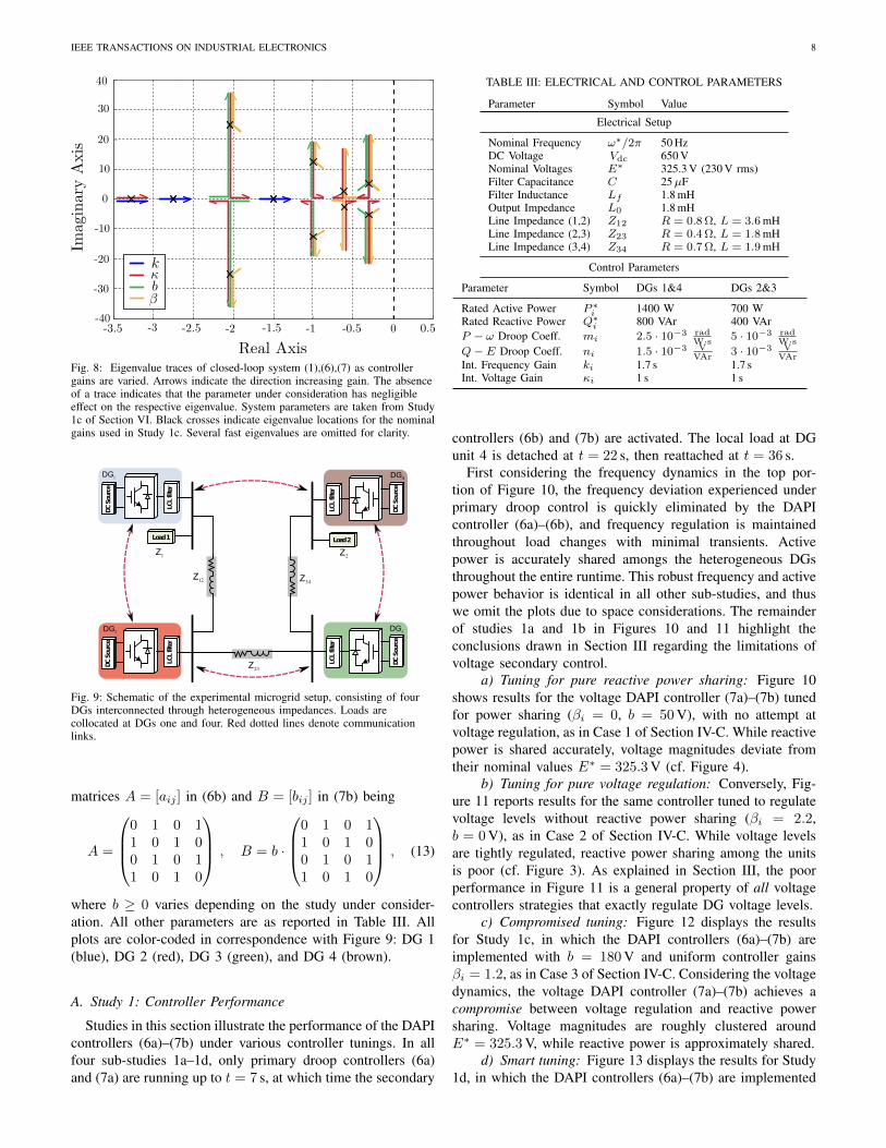
The impact of the controller gains ki, aij , κi, βi and bij onthe steady-state equilibrium was discussed in detail in SectionIV and summarized in Table II. We now examine the impact ofthese controller gains on the system’s transient performance.To do this, we consider a case study with four DGs (Figure 9),with the system parameters of Table III. The communicationnetwork among the DGs is a ring, and the controller gainsaij and bij are given by (13); aij are constants, while bij
are parameterized by a single constant b. For all DGs i =1, . . . , 4, the other control parameters ki, κi and βi are takenas uniform constants k, κ and β, respectively. The nominalvalues for these gains are k = 1.7 s, κ = 1 s, β = 1.2, andb = 180 V (the same as in Study 1c of Section VI).
We increment the gains independently in intervals aroundtheir nominal values, and for each iteration we (i) numericallydetermine the system operating point from (1),(6),(7), (ii) lin-earize the closed-loop system around the operating point, and(iii) plot the eigenvalues of the linearization. These eigenvaluetraces are displayed in Figure 8, where black crosses denotethe eigenvalues for the nominal controller gains and arrowsindicate the direction of increasing gain.
Eigenvalues on the real axis are strongly associated withthe frequency dynamics (6a)–(6b), while complex conjugateeigenvalues are associated with the voltage dynamics (7a)–(7b). These conjugate eigenvalues lead to an underdampedvoltage response: physically, this is a manifestation of theline impedance effect, which the controller (7a)–(7b) mustovercome to establish reactive power sharing. As the frequencytime-constant k is increased (blue), real eigenvalues movetowards the origin leading to slow, smooth frequency/activepower response. Conversely, decreasing k leads to fast (butstill overdamped) frequency regulation. Increasing aij hasan effect nearly identical to decreasing k, and we havetherefore omitted the trace and held aij constant. Increasingthe voltage time-constant κ (red) causes the underdampedconjugate eigenvalues to collapse onto the real axis, leading toan overdamped voltage/reactive power response for sufficientlyslow secondary control. Increasing either feedback gain b orβ (green and gold) results in an increasingly underdampedvoltage/reactive power response.
Taken together, Table II, the stability conditions (12), andthe eigenvalue traces of Figure 8 provide a solid foundation forunderstanding the DAPI controllers (6)–(7). Our experimentalresults demonstrate that despite the simplifying assumptionsin the preceding analysis, the DAPI controllers (6)–(7) can betuned for both stability and high performance.
VI. EXPERIMENTAL RESULTS
Experiments were performed at the Intelligent MicrogridLaboratory (Aalborg University, Denmark) to validate theDAPI controllers presented in Section IV. A schematic of theexperimental setup is shown in Figure 9, consisting of fourDGs interconnected through impedances. Loads are presentlocally at units 1 and 4, and units 1 and 4 are rated fortwice as much power as units 1 and 3 (Table III). The DAPIcontrollers (6a)–(7b) were implemented in Simulink R©, withmeasurements recorded via a dSPACE R© 1006. See [2], [3]for details on the inner voltage, current and impedance controlloops.
This section is organized into four studies, beginning with acharacterization of controller performance, and then examiningrobustness under communication link failure, heterogeneouscontroller gains, and plug-and-play operation. The commu-nication structure is shown in Figure 9, with the adjacency
IEEE TRANSACTIONS ON INDUSTRIAL ELECTRONICS 8
Fig. 8: Eigenvalue traces of closed-loop system (1),(6),(7) as controllergains are varied. Arrows indicate the direction increasing gain. The absenceof a trace indicates that the parameter under consideration has negligibleeffect on the respective eigenvalue. System parameters are taken from Study1c of Section VI. Black crosses indicate eigenvalue locations for the nominalgains used in Study 1c. Several fast eigenvalues are omitted for clarity.
DCSource
LCLfilter
DCSource
LCLfilter
DCSource
LCLfilter
4DG
DCSource
LCLfilter
1DG
2DG 3DG
Load1 Load2
12Z
23Z
34Z
1Z 2Z
Fig. 9: Schematic of the experimental microgrid setup, consisting of fourDGs interconnected through heterogeneous impedances. Loads arecollocated at DGs one and four. Red dotted lines denote communicationlinks.
matrices A = [aij ] in (6b) and B = [bij ] in (7b) being
A =
0 1 0 11 0 1 00 1 0 11 0 1 0
, B = b ·
0 1 0 11 0 1 00 1 0 11 0 1 0
, (13)
where b ≥ 0 varies depending on the study under consider-ation. All other parameters are as reported in Table III. Allplots are color-coded in correspondence with Figure 9: DG 1(blue), DG 2 (red), DG 3 (green), and DG 4 (brown).
A. Study 1: Controller Performance
Studies in this section illustrate the performance of the DAPIcontrollers (6a)–(7b) under various controller tunings. In allfour sub-studies 1a–1d, only primary droop controllers (6a)and (7a) are running up to t = 7 s, at which time the secondary
TABLE III: ELECTRICAL AND CONTROL PARAMETERS
Parameter Symbol Value
Electrical Setup
Nominal Frequency ω∗/2π 50 HzDC Voltage Vdc 650 VNominal Voltages E∗ 325.3 V (230 V rms)Filter Capacitance C 25µFFilter Inductance Lf 1.8 mHOutput Impedance L0 1.8 mHLine Impedance (1,2) Z12 R = 0.8 Ω, L = 3.6 mHLine Impedance (2,3) Z23 R = 0.4 Ω, L = 1.8 mHLine Impedance (3,4) Z34 R = 0.7 Ω, L = 1.9 mH
Control Parameters
Parameter Symbol DGs 1&4 DGs 2&3
Rated Active Power P ∗i 1400 W 700 WRated Reactive Power Q∗i 800 VAr 400 VArP − ω Droop Coeff. mi 2.5 · 10−3 rad
W·s 5 · 10−3 radW·s
Q− E Droop Coeff. ni 1.5 · 10−3 VVAr
3 · 10−3 VVAr
Int. Frequency Gain ki 1.7 s 1.7 sInt. Voltage Gain κi 1 s 1 s
controllers (6b) and (7b) are activated. The local load at DGunit 4 is detached at t = 22 s, then reattached at t = 36 s.
First considering the frequency dynamics in the top por-tion of Figure 10, the frequency deviation experienced underprimary droop control is quickly eliminated by the DAPIcontroller (6a)–(6b), and frequency regulation is maintainedthroughout load changes with minimal transients. Activepower is accurately shared amongs the heterogeneous DGsthroughout the entire runtime. This robust frequency and activepower behavior is identical in all other sub-studies, and thuswe omit the plots due to space considerations. The remainderof studies 1a and 1b in Figures 10 and 11 highlight theconclusions drawn in Section III regarding the limitations ofvoltage secondary control.
a) Tuning for pure reactive power sharing: Figure 10shows results for the voltage DAPI controller (7a)–(7b) tunedfor power sharing (βi = 0, b = 50 V), with no attempt atvoltage regulation, as in Case 1 of Section IV-C. While reactivepower is shared accurately, voltage magnitudes deviate fromtheir nominal values E∗ = 325.3 V (cf. Figure 4).
b) Tuning for pure voltage regulation: Conversely, Fig-ure 11 reports results for the same controller tuned to regulatevoltage levels without reactive power sharing (βi = 2.2,b = 0 V), as in Case 2 of Section IV-C. While voltage levelsare tightly regulated, reactive power sharing among the unitsis poor (cf. Figure 3). As explained in Section III, the poorperformance in Figure 11 is a general property of all voltagecontrollers strategies that exactly regulate DG voltage levels.
c) Compromised tuning: Figure 12 displays the resultsfor Study 1c, in which the DAPI controllers (6a)–(7b) areimplemented with b = 180 V and uniform controller gainsβi = 1.2, as in Case 3 of Section IV-C. Considering the voltagedynamics, the voltage DAPI controller (7a)–(7b) achieves acompromise between voltage regulation and reactive powersharing. Voltage magnitudes are roughly clustered aroundE∗ = 325.3 V, while reactive power is approximately shared.
d) Smart tuning: Figure 13 displays the results for Study1d, in which the DAPI controllers (6a)–(7b) are implemented

IEEE TRANSACTIONS ON INDUSTRIAL ELECTRONICS 9
0 10 20 30 40 5049.5
49.6
49.7
49.8
49.9
50
50.1
Voltage Frequency
Time (s)
Frequency(H
z)
0 10 20 30 40 50200
300
400
500
600
700
800
900
1000
1100
1200
Active Power Injections
Time (s)
Power(W
)
0 10 20 30 40 500
0.5
1
1.5
2
2.5
3
DAPI Outputs (Ω)
Time (s)
Frequency(H
z)
0 10 20 30 40 50300
301
302
303
304
305
306
307
308
Voltage Magnitudes
Time (s)
Voltage(V
)
0 10 20 30 40 50100
150
200
250
300
350
400
Reactive Power Injections
Time (s)
Power(V
Ar)
0 10 20 30 40 50−3
−2
−1
0
1
2
3
DAPI Outputs (e)
Time (s)
Voltage(V
)
Fig. 10: Study 1a – reactive power sharing without voltage regulation, with control parameters b = 50 V, β1 = β2 = β3 = β4 = 0. In correspondence withFigure 4 of Section III, the quality of voltage regulation is quite poor.
0 10 20 30 40 50300
305
310
315
320
325
330
Voltage Magnitudes
Time (s)
Voltage(V
)
0 10 20 30 40 50−500
0
500
1000
Reactive Power Injections
Time (s)
Power(V
Ar)
0 10 20 30 40 500
5
10
15
20
25
30
35
40
DAPI Outputs (e)
Time (s)
Voltage(V
)
Fig. 11: Study 1b – voltage regulation without reactive power sharing, with parameters b = 0 V, β1 = β2 = β3 = β4 = 2.2. In correspondence with Figure3 of Section III, the quality of reactive power sharing is quite poor.
0 10 20 30 40 50300
305
310
315
320
325
330
Voltage Magnitudes
Time (s)
Voltage(V
)
0 10 20 30 40 50100
150
200
250
300
350
400
450
500
Reactive Power Injections
Time (s)
Power(V
Ar)
0 10 20 30 40 500
5
10
15
20
25
30
DAPI Outputs (e)
Time (s)
Voltage(V
)
Fig. 12: Study 1c – a compromise between voltage regulation and reactive power sharing, with control parameters β1 = β2 = β3 = β4 = 1.2, b = 180 V.
with b = 100 V and β2 = 4, β1 = β3 = β4 = 0, in accordancewith the discussion of Case 4 in Section IV-C. In comparisonwith the voltage dynamics of Study 1c, the voltage regulationin Figure 13 shows a slight improvement, while the reactivepower sharing is noticeably improved, maintaining accurate
sharing through load changes and during transients. Notethat this performance improvement has been achieved whilereducing the controller gain b which enforces reactive powersharing. Due to this reduction in controller gain, the ringingin the reactive power signal during transients is noticeably

IEEE TRANSACTIONS ON INDUSTRIAL ELECTRONICS 10
0 10 20 30 40 50300
305
310
315
320
325
330
Voltage Magnitudes
Time (s)
Voltage(V
)
0 10 20 30 40 50100
150
200
250
300
350
400
450
500
Reactive Power Injections
Time (s)
Power(V
Ar)
0 10 20 30 40 500
5
10
15
20
25
30
DAPI Outputs (e)
Time (s)
Voltage(V
)
Fig. 13: Study 1d – accurate reactive power sharing and good voltage regulation, with control parameters β1 = β3 = β4 = 0, β2 = 4 and b = 100 V.
improved from Study 1c to Study 1d, in agreement with thestability and root locus analyses of Section V.
B. Study 2: Communication Link Failure
In this study the communication link (Figure 9) between DGunits 3 and 4 fails at t = 2 s. At t = 7 s the local load at unit 4is detached, and is reattached at t = 18 s. Control parametersare the same as in Study 1d. As the results in Figure 14 show,the DAPI controllers (6a)–(7b) maintain the high performancefrom Study 1d despite the absence of the communication linkbetween DG units 3 and 4 (cf. Remark 2).
C. Study 3: Non-Uniform Controller Gains
We examine the behavior of the frequency DAPI controller(6a)–(6b) under inhomogeneous controller gains. Control pa-rameters are the same as in Study 1d, except for variationsin the integral gains k1 = 1.5 s, k2 = 1 s, k3 = 2 s andk4 = 0.5 s. The results are displayed in Figure 15. Note thatthe inhomogeneous controller gains leads to varying transientresponses for the DGs, but the steady-state behavior andstability of the system is unchanged. This illustrates the utilityof the gains ki and κi in tuning the transient response of theDAPI-controlled microgrid.
D. Study 4: Plug-and-Play Functionality
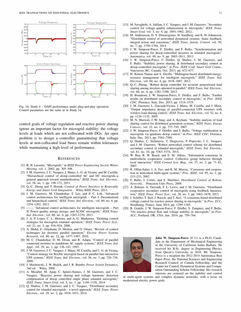
The plug-and-play functionality of the controllers was testedby disconnecting unit 3 at t = 10 s, and reconnecting it att = 30 s. A synchronization process was used in the downtimeto synchronize unit 3 with the remaining microgrid beforereconnection. Control parameters are the same as in Study1d, and the results are displayed in Figure 16. As in previousexperiments, the DAPI controllers (6a)–(7b) maintain accuratepower sharing and frequency and voltage regulation before,during, and after the plug-and-play procedure, with minimaltransients. The bus voltages and bus frequencies remain wellregulated despite the disconnection of DG 3.
VII. CONCLUSIONS
We have introduced a general distributed control method-ology for primary/secondary control in islanded microgrids.By leveraging distributed averaging algorithms from multi-agent systems, the DAPI controllers achieve frequency reg-ulation while sharing active power proportionally, and can
0 5 10 15 20 25 3049.9
49.92
49.94
49.96
49.98
50
50.02
50.04
50.06
50.08
50.1
Voltage Frequency
Time (s)
Frequency(H
z)
0 5 10 15 20 25 30322
323
324
325
326
327
328
329
330
Voltage Magnitudes
Time (s)
Voltage(V
)
0 5 10 15 20 25 30200
300
400
500
600
700
800
900
1000
1100
1200
Active Power Injections
Time (s)
Power(W
)
0 5 10 15 20 25 30100
150
200
250
300
350
400
450
500
Reactive Power Injections
Time (s)
Power(V
Ar)
0 5 10 15 20 25 301.6
1.8
2
2.2
2.4
2.6
DAPI Outputs (Ω)
Time (s)
Frequency(H
z)
0 5 10 15 20 25 3018
19
20
21
22
23
24
25
26
27
28
DAPI Outputs (e)
Time (s)
Voltage(V
)
Fig. 14: Study 2 – DAPI performance under communication link failure.Control parameters are the same as in Study 1d.
0 5 10 15 20 25 3049.9
49.92
49.94
49.96
49.98
50
50.02
50.04
50.06
50.08
50.1
Voltage Frequency
Time (s)
Frequency(H
z)
0 5 10 15 20 25 30200
300
400
500
600
700
800
900
1000
1100
1200
Active Power Injections
Time (s)
Power(W
)
Fig. 15: Study 3 – DAPI performance with heterogeneous controller gains.Control parameters are the same as in Study 1d.
be tuned to achieve either voltage regulation, reactive powersharing, or a compromise between the two. A small-signalstability analysis has been presented for the voltage DAPIcontroller along with a performance study, and the controllershave been validated through extensive experimental testing.
Large-signal stability of the voltage controller (7a)-(7b)remains an open analysis problem. Moreover, the secondary
IEEE TRANSACTIONS ON INDUSTRIAL ELECTRONICS 11
0 10 20 30 40 5049.9
49.92
49.94
49.96
49.98
50
50.02
50.04
50.06
50.08
50.1
Voltage Frequency
Time (s)
Frequency(H
z)
0 10 20 30 40 50320
321
322
323
324
325
326
327
328
329
330
Voltage Magnitudes
Time (s)
Voltage(V
)
0 10 20 30 40 500
500
1000
1500
Active Power Injections
Time (s)
Power(W
)
0 10 20 30 40 500
100
200
300
400
500
600
Reactive Power Injections
Time (s)
Power(V
Ar)
Fig. 16: Study 4 – DAPI performance under plug-and-play operation.Control parameters are the same as in Study 1d.
control goals of voltage regulation and reactive power sharingignore an important factor for microgrid stability: the voltagelevels at loads which are not collocated with DGs. An openproblem is to design a controller guaranteeing that voltagelevels at non-collocated load buses remain within toleranceswhile maintaining a high level of performance.
REFERENCES
[1] R. H. Lasseter, “Microgrids,” in IEEE Power Engineering Society WinterMeeting, vol. 1, 2002, pp. 305–308.
[2] J. M. Guerrero, J. C. Vasquez, J. Matas, L. G. de Vicuna, and M. Castilla,“Hierarchical control of droop-controlled AC and DC microgrids–ageneral approach toward standardization,” IEEE Trans. Ind. Electron.,vol. 58, no. 1, pp. 158–172, 2011.
[3] Q.-C. Zhong and T. Hornik, Control of Power Inverters in RenewableEnergy and Smart Grid Integration. Wiley-IEEE Press, 2013.
[4] J. M. Guerrero, M. Chandorkar, T. Lee, and P. C. Loh, “Advancedcontrol architectures for intelligent microgrids – Part I: Decentralizedand hierarchical control,” IEEE Trans. Ind. Electron., vol. 60, no. 4, pp.1254–1262, 2013.
[5] ——, “Advanced control architectures for intelligent microgrids – PartII: Power quality, energy storage, and AC/DC microgrids,” IEEE Trans.Ind. Electron., vol. 60, no. 4, pp. 1263–1270, 2013.
[6] J. A. P. Lopes, C. L. Moreira, and A. G. Madureira, “Defining controlstrategies for microgrids islanded operation,” IEEE Trans. Power Syst.,vol. 21, no. 2, pp. 916–924, 2006.
[7] A. Mohd, E. Ortjohann, D. Morton, and O. Omari, “Review of controltechniques for inverters parallel operation,” Electric Power SystemsResearch, vol. 80, no. 12, pp. 1477–1487, 2010.
[8] M. C. Chandorkar, D. M. Divan, and R. Adapa, “Control of parallelconnected inverters in standalone AC supply systems,” IEEE Trans. Ind.Appl., vol. 29, no. 1, pp. 136–143, 1993.
[9] J. M. Guerrero, J. C. Vasquez, J. Matas, M. Castilla, and L. G. de Vicuna,“Control strategy for flexible microgrid based on parallel line-interactiveUPS systems,” IEEE Trans. Ind. Electron., vol. 56, no. 3, pp. 726–736,2009.
[10] J. Machowski, J. W. Bialek, and J. R. Bumby, Power System Dynamics,2nd ed. Wiley, 2008.
[11] A. Micallef, M. Apap, C. Spiteri-Staines, J. M. Guerrero, and J. C.Vasquez, “Reactive power sharing and voltage harmonic distortioncompensation of droop controlled single phase islanded microgrids,”IEEE Trans. Smart Grid, vol. 5, no. 3, pp. 1149–1158, 2014.
[12] Q. Shafiee, J. M. Guerrero, and J. C. Vasquez, “Distributed secondarycontrol for islanded microgrids - a novel approach,” IEEE Trans. PowerElectron., vol. 29, no. 2, pp. 1018–1031, 2014.
[13] M. Savaghebi, A. Jalilian, J. C. Vasquez, and J. M. Guerrero, “Secondarycontrol for voltage quality enhancement in microgrids,” IEEE Trans.Smart Grid, vol. 3, no. 4, pp. 1893–1902, 2012.
[14] M. Andreasson, D. V. Dimarogonas, H. Sandberg, and K. H. Johansson,“Distributed control of networked dynamical systems: Static feedback,integral action and consensus,” IEEE Trans. Autom. Control, vol. 59,no. 7, pp. 1750–1764, 2014.
[15] J. W. Simpson-Porco, F. Dorfler, and F. Bullo, “Synchronization andpower sharing for droop-controlled inverters in islanded microgrids,”Automatica, vol. 49, no. 9, pp. 2603–2611, 2013.
[16] J. W. Simpson-Porco, F. Dorfler, Q. Shafiee, J. M. Guerrero, andF. Bullo, “Stability, power sharing, & distributed secondary control indroop-controlled microgrids,” in Proc. IEEE Conf. Smart Grid Comm.,Vancouver, BC, Canada, Oct. 2013, pp. 672–677.
[17] H. Kumar Nunna and S. Doolla, “Multiagent-based distributed-energy-resource management for intelligent microgrids,” IEEE Trans. Ind.Electron., vol. 60, no. 4, pp. 1678–1687, 2013.
[18] Q.-C. Zhong, “Robust droop controller for accurate proportional loadsharing among inverters operated in parallel,” IEEE Trans. Ind. Electron.,vol. 60, no. 4, pp. 1281–1290, 2013.
[19] H. Bouattour, J. W. Simpson-Porco, F. Dorfler, and F. Bullo, “Furtherresults on distributed secondary control in microgrids,” in Proc. IEEECDC, Florence, Italy, Dec. 2013, pp. 1514–1519.
[20] J. M. Guerrero, L. GarciadeVicuna, J. Matas, M. Castilla, and J. Miret,“Output impedance design of parallel-connected UPS inverters withwireless load-sharing control,” IEEE Trans. Ind. Electron., vol. 52, no. 4,pp. 1126–1135, 2005.
[21] M. N. Marwali, J.-W. Jung, and A. Keyhani, “Stability analysis of loadsharing control for distributed generation systems,” IEEE Trans. EnergyConvers., vol. 22, no. 3, pp. 737–745, 2007.
[22] J. W. Simpson-Porco, F. Dorfler, and F. Bullo, “Voltage stabilization inmicrogrids via quadratic droop control,” in Proc. IEEE CDC, Florence,Italy, Dec. 2013, pp. 7582–7589.
[23] Q. Shafiee, C. Stefanovic, T. Dragicevic, P. Popovski, J. C. Vasquez,and J. M. Guerrero, “Robust networked control scheme for distributedsecondary control of islanded microgrids,” IEEE Trans. Ind. Electron.,vol. 61, no. 10, pp. 5363–5374, 2014.
[24] W. Ren, R. W. Beard, and E. M. Atkins, “Information consensus inmultivehicle cooperative control: Collective group behavior throughlocal interaction,” IEEE Control Syst. Mag., vol. 27, no. 2, pp. 71–82,2007.
[25] R. Olfati-Saber, J. A. Fax, and R. M. Murray, “Consensus and coopera-tion in networked multi-agent systems,” Proc. IEEE, vol. 95, no. 1, pp.215–233, 2007.
[26] F. Bullo, J. Cortes, and S. Martınez, Distributed Control of RoboticNetworks. Princeton Univ Press, 2009.
[27] A. Bidram, A. Davoudi, F. L. Lewis, and J. M. Guerrero, “Distributedcooperative secondary control of microgrids using feedback lineariza-tion,” IEEE Trans. Power Syst., vol. 28, no. 3, pp. 3462–3470, 2013.
[28] J. Schiffer, T. Seel, J. Raisch, and T. Sezi, “A consensus-based distributedvoltage control for reactive power sharing in microgrids,” in Proc. ECC,Strasbourg, France, June 2014, pp. 1299–1305.
[29] B. Gentile, J. W. Simpson-Porco, F. Dorfler, S. Zampieri, and F. Bullo,“On reactive power flow and voltage stability in microgrids,” in Proc.ACC, Portland, OR, USA, Jun. 2014, pp. 759–764.
John W. Simpson-Porco (S’11) is a Ph.D. Candi-date in the Department of Mechanical Engineeringat the University of California Santa Barbara. Hereceived his B.Sc. degree in Engineering Physicsfrom Queen’s University in 2010. Mr. Simpson-Porco is a recipient the 2012-2014 Automatica BestPaper Prize, the National Sciences and EngineeringResearch Council of Canada Fellowship, and theCenter for Control, Dynamical Systems and Compu-tation Outstanding Scholar Fellowship. His researchinterests are centered on the stability and control
of multi-agent systems and complex dynamic networks, with a focus onmodernized electric power grids.

IEEE TRANSACTIONS ON INDUSTRIAL ELECTRONICS 12
Qobad Shafiee (S’13–M’15) received the M.S. de-gree in electrical engineering from the Iran Uni-versity of Science and Technology, Tehran, Iran,in 2007, and the PhD degree in power electronicsand Microgrids from the Department of EnergyTechnology, Aalborg University, Aalborg, Denmark,in 2014. He worked with Department of Electricaland Computer Engineering, University of Kurdistan,Sanandaj, Iran, from 2007 to 2011, where he taughtseveral electrical engineering courses and conductedresearch on load frequency control of power sys-
tems. From March 2014 to June 2014, he was a visiting researcher at theElectrical Engineering Department, University of Texas-Arlington, Arlington,TX, USA. Currently, he is a postdoctoral researcher at the Department ofEnergy Technology, Aalborg University. His main research interests includemodeling, power management, hierarchical and distributed control applied todistributed generation in Microgrids.
Florian Dorfler (S’09–M’13) is an Assistant Pro-fessor at the Automatic Control Laboratory at ETHZrich. He received his Ph.D. degree in Mechani-cal Engineering from the University of Californiaat Santa Barbara in 2013, and a Diplom degreein Engineering Cybernetics from the University ofStuttgart in 2008. From 2013 to 2014 he was an As-sistant Professor at the University of California LosAngeles. His primary research interests are centeredaround distributed control, complex networks, andcyberphysical systems currently with applications in
energy systems and smart grids. He is a recipient of the 2009 Regents SpecialInternational Fellowship, the 2011 Peter J. Frenkel Foundation Fellowship, the2010 ACC Student Best Paper Award, the 2011 O. Hugo Schuck Best PaperAward, and the 2012-2014 Automatica Best Paper Award. As a co-advisorand a co-author, he has been a finalist for the ECC 2013 Best Student PaperAward.
Juan C. Vasquez (M’12–SM’15) received theB.S. degree in electronics engineering from theAutonomous University of Manizales, Manizales,Colombia, and the Ph.D. degree in automatic con-trol, robotics, and computer vision from the Tech-nical University of Catalonia, Barcelona, Spain, in2004 and 2009, respectively. He was with the Au-tonomous University of Manizales, where he hasbeen teaching courses on digital circuits, servo sys-tems and flexible manufacturing systems. In 2009,he worked as Post-doctoral Assistant with the De-
partment of Automatic Control Systems and Computer engineering, TechnicalUniversity of Catalonia, where he taught courses based on renewable energysystems, and power management on ac/dc minigrids and Microgrids. Since2011, he has been an Assistant Professor in Microgrids at the Department ofEnergy Technology, Aalborg University, Denmark, where he is co-responsibleof the Microgrids research programme and co-advising more than 10 PhDstudents and a number of international visitors in research experience. Heis a visiting scholar at the Center for Power Electronics Systems CPESat Virginia Tech, Blacksburg, VA, USA. He has published more than 100journal and conference papers and holds a pending patent. His current researchinterests include operation, energy management, hierarchical and cooperativecontrol, energy management systems and optimization applied to DistributedGeneration in AC/DC Microgrids. Dr Vasquez is member of the TechnicalCommittee on Renewable Energy Systems TC-RES of the IEEE IndustrialElectronics Society and the IEC System Evaluation Group SEG 4 workon LVDC Distribution and Safety for use in Developed and DevelopingEconomies.
Josep M. Guerrero (S’01–M’04–SM’08–F’15) re-ceived the B.S. degree in telecommunications engi-neering, the M.S. degree in electronics engineering,and the Ph.D. degree in power electronics fromthe Technical University of Catalonia, Barcelona, in1997, 2000 and 2003, respectively. Since 2011, hehas been a Full Professor with the Department ofEnergy Technology, Aalborg University, Denmark,where he is responsible for the Microgrid ResearchProgram. From 2012 he is a guest Professor atthe Chinese Academy of Science and the Nanjing
University of Aeronautics and Astronautics; from 2014 he is chair Professorin Shandong University; and from 2015 he is a distinguished guest Professor inHunan University. His research interests is oriented to different microgrid as-pects, including power electronics, distributed energy-storage systems, hierar-chical and cooperative control, energy management systems, and optimizationof microgrids and islanded minigrids. Prof. Guerrero is an Associate Editorfor the IEEE TRANSACTIONS ON POWER ELECTRONICS, the IEEETRANSACTIONS ON INDUSTRIAL ELECTRONICS, and the IEEE Indus-trial Electronics Magazine, and an Editor for the IEEE TRANSACTIONS onSMART GRID and IEEE TRANSACTIONS on ENERGY CONVERSION.He has been Guest Editor of the IEEE TRANSACTIONS ON POWERELECTRONICS Special Issues: Power Electronics for Wind Energy Con-version and Power Electronics for Microgrids; the IEEE TRANSACTIONSON INDUSTRIAL ELECTRONICS Special Sections: Uninterruptible PowerSupplies systems, Renewable Energy Systems, Distributed Generation andMicrogrids, and Industrial Applications and Implementation Issues of theKalman Filter; and the IEEE TRANSACTIONS on SMART GRID SpecialIssue on Smart DC Distribution Systems. He was the chair of the RenewableEnergy Systems Technical Committee of the IEEE Industrial ElectronicsSociety. In 2014 he was awarded by Thomson Reuters as Highly CitedResearcher, and in 2015 he was elevated as IEEE Fellow for his contributionson distributed power systems and microgrids.
Francesco Bullo (S’95–M’99–SM’03-F’10) is aProfessor with the Mechanical Engineering Depart-ment and the Center for Control, Dynamical Systemsand Computation at the University of California,Santa Barbara. He was previously associated withthe University of Padova, the California Institute ofTechnology and the University of Illinois at Urbana-Champaign. His main research interests are networksystems and distributed control with application torobotic coordination, power grids and social net-works. He is the coauthor of ”Geometric Control
of Mechanical Systems” (Springer, 2004, 0-387-22195-6) and ”DistributedControl of Robotic Networks” (Princeton, 2009, 978-0-691-14195-4). Hereceived the 2008 IEEE CSM Outstanding Paper Award, the 2010 HugoSchuck Best Paper Award, the 2013 SIAG/CST Best Paper Prize, and the 2014IFAC Automatica Best Paper Award. He has served on the editorial boardsof IEEE Transactions on Automatic Control, ESAIM: Control, Optimization,and the Calculus of Variations, SIAM Journal of Control and Optimization,and Mathematics of Control, Signals, and Systems.