ieee transactions on multimedia, vol. 13, no. 3,...
TRANSCRIPT
IEEE TRANSACTIONS ON MULTIMEDIA, VOL. 13, NO. 3, JUNE 2011 453
Depth Image-Based Rendering With AdvancedTexture Synthesis for 3-D Video
Patrick Ndjiki-Nya, Member, IEEE, Martin Köppel, Dimitar Doshkov, Haricharan Lakshman,Philipp Merkle, Student Member, IEEE, Karsten Müller, Senior Member, IEEE, and Thomas Wiegand, Fellow, IEEE
Abstract—A depth image-based rendering (DIBR) approachwith advanced inpainting methods is presented. The DIBR al-gorithm can be used in 3-D video applications to synthesize anumber of different perspectives of the same scene, e.g., from amultiview-video-plus-depth (MVD) representation. This MVDformat consists of video and depth sequences for a limited numberof original camera views of the same natural scene. Here, DIBRmethods allow the computation of additional new views. An in-herent problem of the view synthesis concept is the fact that imageinformation which is occluded in the original views may becomevisible, especially in extrapolated views beyond the viewing rangeof the original cameras. The presented algorithm synthesizes theseoccluded textures. The synthesizer achieves visually satisfyingresults by taking spatial and temporal consistency measures intoaccount. Detailed experiments show significant objective andsubjective gains of the proposed method in comparison to thestate-of-the-art methods.
Index Terms—Depth image based rendering, inpainting, texturesynthesis, view synthesis, 3-D video.
I. INTRODUCTION
T HREE-DIMENSIONAL (3-D) video is rapidly growingin popularity as many stereo video products are currently
entering the mass market. The viewing of stereo video on amulti-user stereo display requires the use of additional eye-glasses. Autostereoscopic multiview displays (we call them3-D displays) provide 3-D depth perception without the needto wear additional eyeglasses by showing a number of slightlydifferent views simultaneously. The various views for the 3-Ddisplay are typically generated from fewer images capturedby original cameras at different viewpoints and separatedby a baseline corresponding to the human eye distance. 3-Ddisplays ensure that a viewer always sees a stereo pair frompredefined viewpoints. The high number of views required by
Manuscript received November 01, 2010; revised February 28, 2011; ac-cepted March 08, 2011. Date of publication March 17, 2011; date of currentversion May 18, 2011. The associate editor coordinating the review of this man-uscript and approving it for publication was Dr. Homer H. Chen.
P. Ndjiki-Nya, M. Köppel, D. Doshkov, H. Lakshman, P. Merkle and K.Müller are with the Image Processing Department, Fraunhofer Institute forTelecommunications-Heinrich Hertz Institute (HHI), 10587 Berlin, Germany(e-mail: [email protected]; martin.kö[email protected]; [email protected]; [email protected]; [email protected]; [email protected]).
T. Wiegand is with the Image Processing Department, Fraunhofer Institute forTelecommunications-Heinrich Hertz Institute (HHI), 10587 Berlin, Germany,and also with the Department of Telecommunication Systems, School of Elec-trical Engineering and Computer Science, Berlin Institute of Technology, 10587Berlin, Germany (e-mail: [email protected]).
Color versions of one or more of the figures in this paper are available onlineat http://ieeexplore.ieee.org.
Digital Object Identifier 10.1109/TMM.2011.2128862
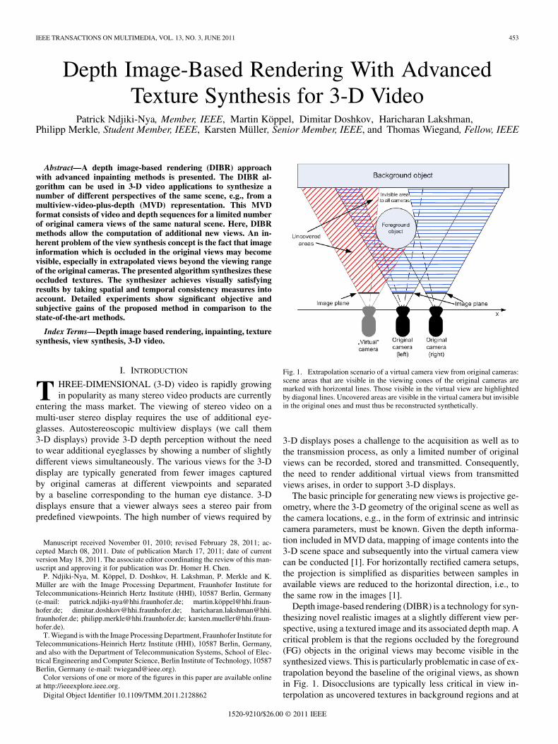
Fig. 1. Extrapolation scenario of a virtual camera view from original cameras:scene areas that are visible in the viewing cones of the original cameras aremarked with horizontal lines. Those visible in the virtual view are highlightedby diagonal lines. Uncovered areas are visible in the virtual camera but invisiblein the original ones and must thus be reconstructed synthetically.
3-D displays poses a challenge to the acquisition as well as tothe transmission process, as only a limited number of originalviews can be recorded, stored and transmitted. Consequently,the need to render additional virtual views from transmittedviews arises, in order to support 3-D displays.
The basic principle for generating new views is projective ge-ometry, where the 3-D geometry of the original scene as well asthe camera locations, e.g., in the form of extrinsic and intrinsiccamera parameters, must be known. Given the depth informa-tion included in MVD data, mapping of image contents into the3-D scene space and subsequently into the virtual camera viewcan be conducted [1]. For horizontally rectified camera setups,the projection is simplified as disparities between samples inavailable views are reduced to the horizontal direction, i.e., tothe same row in the images [1].
Depth image-based rendering (DIBR) is a technology for syn-thesizing novel realistic images at a slightly different view per-spective, using a textured image and its associated depth map. Acritical problem is that the regions occluded by the foreground(FG) objects in the original views may become visible in thesynthesized views. This is particularly problematic in case of ex-trapolation beyond the baseline of the original views, as shownin Fig. 1. Disocclusions are typically less critical in view in-terpolation as uncovered textures in background regions and at
1520-9210/$26.00 © 2011 IEEE
454 IEEE TRANSACTIONS ON MULTIMEDIA, VOL. 13, NO. 3, JUNE 2011
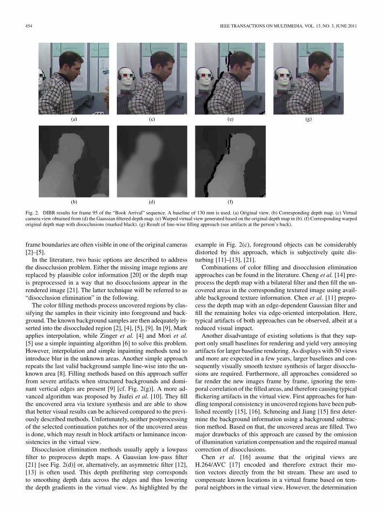
Fig. 2. DIBR results for frame 95 of the “Book Arrival” sequence. A baseline of 130 mm is used. (a) Original view. (b) Corresponding depth map. (c) Virtualcamera view obtained from (d) the Gaussian filtered depth map. (e) Warped virtual view generated based on the original depth map in (b). (f) Corresponding warpedoriginal depth map with disocclusions (marked black). (g) Result of line-wise filling approach (see artifacts at the person’s back).
frame boundaries are often visible in one of the original cameras[2]–[5].
In the literature, two basic options are described to addressthe disocclusion problem. Either the missing image regions arereplaced by plausible color information [20] or the depth mapis preprocessed in a way that no disocclusions appear in therendered image [21]. The latter technique will be referred to as“disocclusion elimination” in the following.
The color filling methods process uncovered regions by clas-sifying the samples in their vicinity into foreground and back-ground. The known background samples are then adequately in-serted into the disoccluded region [2], [4], [5], [9]. In [9], Markapplies interpolation, while Zinger et al. [4] and Mori et al.[5] use a simple inpainting algorithm [6] to solve this problem.However, interpolation and simple inpainting methods tend tointroduce blur in the unknown areas. Another simple approachrepeats the last valid background sample line-wise into the un-known area [8]. Filling methods based on this approach sufferfrom severe artifacts when structured backgrounds and domi-nant vertical edges are present [9] [cf. Fig. 2(g)]. A more ad-vanced algorithm was proposed by Jiufei et al. [10]. They fillthe uncovered area via texture synthesis and are able to showthat better visual results can be achieved compared to the previ-ously described methods. Unfortunately, neither postprocessingof the selected continuation patches nor of the uncovered areasis done, which may result in block artifacts or luminance incon-sistencies in the virtual view.
Disocclusion elimination methods usually apply a lowpassfilter to preprocess depth maps. A Gaussian low-pass filter[21] [see Fig. 2(d)] or, alternatively, an asymmetric filter [12],[13] is often used. This depth prefiltering step correspondsto smoothing depth data across the edges and thus loweringthe depth gradients in the virtual view. As highlighted by the
example in Fig. 2(c), foreground objects can be considerablydistorted by this approach, which is subjectively quite dis-turbing [11]–[13], [21].
Combinations of color filling and disocclusion eliminationapproaches can be found in the literature. Cheng et al. [14] pre-process the depth map with a bilateral filter and then fill the un-covered areas in the corresponding textured image using avail-able background texture information. Chen et al. [11] prepro-cess the depth map with an edge-dependent Gaussian filter andfill the remaining holes via edge-oriented interpolation. Here,typical artifacts of both approaches can be observed, albeit at areduced visual impact.
Another disadvantage of existing solutions is that they sup-port only small baselines for rendering and yield very annoyingartifacts for larger baseline rendering. As displays with 50 viewsand more are expected in a few years, larger baselines and con-sequently visually smooth texture synthesis of larger disocclu-sions are required. Furthermore, all approaches considered sofar render the new images frame by frame, ignoring the tem-poral correlation of the filled areas, and therefore causing typicalflickering artifacts in the virtual view. First approaches for han-dling temporal consistency in uncovered regions have been pub-lished recently [15], [16]. Schmeing and Jiang [15] first deter-mine the background information using a background subtrac-tion method. Based on that, the uncovered areas are filled. Twomajor drawbacks of this approach are caused by the omissionof illumination variation compensation and the required manualcorrection of disocclusions.
Chen et al. [16] assume that the original views areH.264/AVC [17] encoded and therefore extract their mo-tion vectors directly from the bit stream. These are used tocompensate known locations in a virtual frame based on tem-poral neighbors in the virtual view. However, the determination

NDJIKI-NYA et al.: DIBR WITH ADVANCED TEXTURE SYNTHESIS FOR 3-D VIDEO 455
of motion vectors in an H.264/AVC encoder is steered by theoverall encoder optimization used, yielding motion vectorsthat can be rather different from the real motion. The benefitof using these motion vectors is additionally limited by thefact that they are sparsely sampled and thus lack accuracy[18]. Hence, the PSNR and SSIM [19] gains presented in thework by Chen et al. [16] are very small compared with thestate-of-the-art methodology.
As mentioned before [6], [10], texture synthesis [22]–[30]is an appropriate technique for filling missing image regionswith known information. This method operates in parametric[23]–[25] or nonparametric [22], [26]–[30] modes. Parametricsynthesis approaches generate new textures using a compactmodel with a fixed [23], [24] or dynamic [25] parameter set.Nonparametric approaches, on the other hand, typically for-mulate the texture synthesis problem based on the Markovrandom field (MRF) theory [27]–[30]. Nonparametric ap-proaches can be further classified in sample- or patch-basedmethods. Sample-based algorithms update the synthetic tex-ture sample-wise [27], while patch-based approaches apply apatch-wise update [28]–[30], i.e., a set of samples is updatedsimultaneously. Typically nonparametric synthesis approachesyield better inpainting results than parametric algorithms, andin addition they can also be successfully applied to a muchlarger variety of textures [29]. For the restoration of small andrather homogenous regions, inpainting approaches are oftenused that are based on solving partial differential equations(PDEs) [7].
In this paper, a new approach for handling disocclusions insynthesized views for 3-D video is presented. The method isbased on nonparametric texture synthesis. Statistical dependen-cies between different pictures of a sequence are taken into con-sideration via a background (BG) sprite. A robust initializationgives an estimate of the unknown image regions that is refinedduring the synthesis stage.
The remainder of this paper is organized as follows. Theoverall algorithm is presented in Section II. Depth map filling,image initialization, and texture synthesis are presented indetail in Sections III–VI. In Section VII, the experimentalresults are presented. Finally, conclusions and future steps aregiven in Section VIII.
II. PROPOSED VIEW SYNTHESIS FRAMEWORK
The proposed framework for virtual view generation withtime-consistent texture synthesis is outlined in Fig. 3. The tex-ture images and associated depth maps (DMs) of an MVD se-quence are taken as input. DMs are provided with the test data,e.g., by depth estimation methods by Tanimoto et al. in [31].Next, a projection of the original views towards the virtual viewsbased on the DMs is realized with an algorithm similar to [32],where the foreground (FG) and background (BG) objects arewarped separately. This results in an image with holes from dis-occluded background, as shown in Fig. 2(e).
In addition, the DM is also projected [see Fig. 2(f)] for laterforeground–background separation in the texture synthesisstage. According to the original scene capturing setup, back-ground motion in all views may occur. In this case, a motionestimation stage needs to be included in the workflow afterboth projection steps (see Fig. 3) to compensate for the global
Fig. 3. Block diagram of the proposed approach. First, disocclusions in the DMare filled after the projection step by Tanimoto et al. [32]. Next, the BG sprite isupdated with original BG data and the holes in the current picture are updatedfrom the BG sprite. Then, the remaining holes are initialized and refined withtexture synthesis. Finally, the BG sprite is updated with the new synthesizedtexture.
BG motion. In our simulations, we first concentrated on astatic BG similarly to the work of Schmeing and Jiang [15].Note, however, that our algorithm is fully automatic, i.e., nomanual disocclusion correction is required, and can seamlesslycompensate illumination changes.
The goal of the new view synthesis algorithm is to fill thedisocclusions (holes) resulting from the warping process. Theybecome visible both in the virtual DM and the textured imageand must be filled in a visually plausible manner. For videosequences, this includes a temporally stable synthesis result,meaning that information from temporally neighboring framesshould be taken into account. For minimizing the processingdelay, only causal neighbors are considered in this work. Tem-poral consistency is achieved with a BG sprite, which storesbackground information from processed frames. In a first step,the disoccluded areas in the DM are filled as shown in the nextsection. The BG sprite is then updated with known BG infor-mation from the current picture. Next, the holes in the currentpicture are updated from the BG sprite. The remaining holes aretreated by first initializing the area from spatially adjacent orig-inal texture, providing an estimate of the missing information.In the next step, patch-based texture synthesis is used to refinethe initialized area. The BG sprite is finally updated with thesynthesized image information for temporal consistency duringthe filling of holes in the subsequent pictures.
III. FILLING DISOCCLUSIONS IN THE DEPTH MAP
Given the inherent properties of the depth-based imagewarping, larger uncovered areas mostly belong to BG objects.The DM is represented as an 8-b grayscale image, denoted as
in the following. The continuous depth range of the sceneis quantized to the discrete depth values, assigning the value255 to the point that is closest to the camera and 1 to themost distant point [Fig. 4(a)–(c)]. The holes in the DM are

456 IEEE TRANSACTIONS ON MULTIMEDIA, VOL. 13, NO. 3, JUNE 2011
Fig. 4. Results for picture 1 of the “Newspaper” sequence for the proposed depth map and texture filling approach. (a) Depth map with disoccluded area markedblack (filling direction given by white arrows). (b) Result of proposed depth map filling approach. (c) Line-wise filling of depth map without blob removal. (d)Original reference image. (e) Result of the proposed approach. (f) Result of MPEG VSRS.
Fig. 5. (a) Depth map with highlighted neighborhood (square) centered at �. (b) Histogram of considered neighborhood with the two centroids � and � ,clustered via �-means.
currently assigned the value 0. In Fig. 4(a), the uncovered areain the DM is denoted as and the corresponding boundary isdenoted as . thereby corresponds to the outer boundaryof and consists of known background depth values. Due toinaccuracies in depth estimation, FG object boundary samplesmay be warped into [denoted as “blobs” in the following,Fig. 4(a)]. One possibility to proceed is to fill the last knownBG depth value , with line-wise into , as proposedin [8] [Fig. 4(c)].
In this work, small blobs up to samples in are assignedto , as they are assumed to correspond to noise and may other-wise lead to noticeable inaccuracies in the postprocessed DM[see Fig. 4(b) and (c)]. Subsequently, a verified value iscopied line-wise into . It is assumed that relying on a singlevalue of can be error-prone. Hence, the spatial neighbor-hood surrounding location is clustered into two depth classes,whose centroids are represented by and . They rep-resent FG and BG depth values respectively (see Fig. 5). Theneighborhood , is given by a rectangular area of sam-ples and centered at location . and arecomputed via -means clustering [33]. After and
estimation, depth information at locations and on
the same row as is extrapolated. The selection criterion for thedepth values to be filled at locations is defined as follows:
ifotherwise
(1)
where and correspond to the row coordinates of locationsand , respectively. Background–foreground clustering and sub-sequent line-wise filling is done for all .
So far, we have increased the robustness to artifacts indepth-map filling. The computed values are stored inorder to be used for image and sprite updating as explained inthe next section.
IV. SPRITE AND IMAGE UPDATING
The BG information and its associated depth values are storedas a BG sprite, denoted as [cf. Figs. 13(c) and 14(c)] and DMsprite, denoted as [cf. Figs. 13(d) and 14(d)]. These spritesaccumulate valuable information for rendering textured images.In fact, by referencing the sprite samples for filling unknownarea in the current picture, the synthesis is temporally stabilized.

NDJIKI-NYA et al.: DIBR WITH ADVANCED TEXTURE SYNTHESIS FOR 3-D VIDEO 457
A. Sprite Update
For each new picture, denoted as , the depth values of allsample positions are examined to determine thesamples that can be considered for sprite update. For that, thefollowing content-adaptive threshold is required:
if is odd
if is even
(2)
where is the median value of the sorted values denotedas . Hence, all samples with a depth valuebelow are eligible for sprite update.
Depth values below are assumed to describe the BG,while the remaining values are assigned to the FG. Due to thementioned inaccuracies in the depth estimation step, depth esti-mates along background–foreground transitions and within theuncovered area in , denoted as , are considered as being un-reliable. Therefore, a two-sample-wide area around the unreli-able regions is not considered for sprite update. The remaininglocations with are stored in the BG sprite , and DMsprite , respectively, where previously assigned color or depthinformation is overwritten in and . After the synthesis step(cf. Sections V and VI), newly synthesized textures and depthsare incorporated into the sprites as well.
B. Textured Image Update
The disoccluded regions of every picture are updated fromthe BG sprite . Sample positions corresponding to samples inthe BG sprite with unknown background information are ig-nored. The sample positions in to be used for the update ofthe current picture are selected as follows:
ifotherwise
(3)
where represent the intensity value at location in thecurrent picture and the BG sprite, respectively. andrepresent the depth value at location in the extrapolated DMand the DM sprite, respectively. The parameter allows forsome variance in the local BG depth value. The disoccludedarea in is denoted as . Note that (3) is applied to the chromachannels in the same way.
In order to account for illumination variations, the covariantcloning method [30], [34], [35] is utilized to fit the BG spritesamples to the intensity distribution in the relevant neighbor-hood of the current picture. The term “cloning” or “seamlesscloning” denotes the process of replacing a region of a given pic-ture by another content (often from a different picture), such thatsubjective impairments are minimized. In [38] Poisson cloningis used in texture synthesis to reduce the photometric seams inthe gradient domain.
In order to explain the cloning principle, we define as aknown scalar function over the domain . As indi-cated in Fig. 6(a), represents the boundary of the unknownarea . is a function defined over the texture source tobe (partially) mapped onto . is an unknown scalar functiondefined over .
Fig. 6. (a) Seamless cloning principle. (b) Cloning application to the view syn-thesis framework.
The aim is to find using the source function and the in-formation available in . This boundary value problem can beexpressed as [34]
(4)
with the Dirichlet boundary condition
(5)
where represents the Laplacian operator. In this way, infor-mation on the boundary is diffused into , such that thetransition between the source function and is smooth.
The notations of covariant cloning, in the context of theproposed view synthesis framework, are illustrated in Fig. 6(b).It can be seen that boundaries of the area covered by the BGsprite, when mapped onto in the current picture , are eitheradjacent to the nonreconstructed area or directly to the FGobject [not shown in Fig. 6(b)]. In this case the BG sprite area isrepresented by . The cloned BG sprite area then correspondsto . As can be seen in Fig. 6(b), may remain partiallyunknown. The current image is denoted as and the boundary
comprises the spatial neighbors of the BG sprite samples.Due to the presence of uncovered areas (FG objects), theboundary conditions (5) for the region are incomplete, i.e.,
is undefined at these edges. Therefore, the cloning methodis adapted to the given view synthesis framework by ensuringthat only BG samples in the current picture are considered asvalid boundary conditions:
defaultif undefined.
(6)
This modified boundary condition implies that the colorinformation is only diffused into the BG sprite samples fromthose boundaries for which is defined. This diffusionprocess is also called photometric correction. Please note thatfor simplifying the cloning approach, the quotient from(4) is approximated by a constant. We set , whichtransforms (4) exactly to the corresponding one in the work byPérez et al. [36].
V. INITIALIZATION OF TEXTURED IMAGES
The disocclusions remaining after sprite and image updatingare preprocessed through a new texture initialization algorithm.In a first step, the Laplacian equation [36] is used to fill smallholes in the current image [Fig. 7(a) and (c)]. For the recon-struction of smooth regions this method gives satisfactory re-

458 IEEE TRANSACTIONS ON MULTIMEDIA, VOL. 13, NO. 3, JUNE 2011
Fig. 7. Results for hole filling with Laplacian cloning. Disoccluded areas:(a) black or (c) white. (b), (d) Filled disocclusions.
sults [Fig. 7(b) and (d)]. Good visual results are observed forholes smaller than samples (e.g., 50 samples), where Laplacecloning is about 10 times faster than patch-based texture syn-thesis (cf. Section VI). Hence, after Laplace cloning, small holesare regarded as finally filled and are not considered in the tex-ture refinement step.
For holes larger than samples, we have shown in our pre-vious work [37] that the visual results of texture synthesis canbe improved by using an initial estimate of sample values. Inthis paper, we present an initialization method that is based onthe statistical properties of known samples in the vicinity of .Generally, the known samples constitute valid BG samples, butin some cases the depth values at the foreground–backgroundtransition are not reliable. Hence, the probability distribution ofknown BG sample values in the spatial neighborhood of the holearea is observed to be skewed.
In order to determine the BG value from spatially adjacentsamples, the median estimator is used, which is the standardmeasure of (end value) location used in case of skewed distribu-tions. A window of samples sized 32 32 and centered aroundthe sample to be filled is considered. For each unknown sample,a measure is set equal to the number of known samplesthat are classified as BG in the current window. The unknownsamples are visited in decreasing order of . A 2-D medianfilter operates on the BG samples in the current window andthe filtered output is used to initialize the unknown sample. Thefiltering operation can be viewed as the process of extractinga valid BG value from the spatially neighboring samples. Thisserves as a coarse estimate that can be used at the texture syn-thesis stage to recover the details in the unknown region. Usingthe described initialization scheme, the sensitivity of the texturesynthesis stage to outliers is significantly reduced.
Fig. 8. Hole-filling order from background data at the texture refinement step.
VI. TEXTURE REFINEMENT VIA SYNTHESIS
In texture synthesis techniques the unknown region is synthe-sized by copying content from the known parts to themissing parts of the image. Patch-based texture synthesisis used in this work to refine the initialized areas. The patchfilling order criterion introduced by Criminisi et al. [22] is uti-lized. They determine the current filling position at via apriority term. The priority is the product of the confidence termand the data term. The confidence term enforces a concentricfilling order, while the data term encourages linear structures tobe synthesized first. Their approach is enhanced in two ways inthis work. First, the gradient is calculated for the original as wellas the initialized samples (Fig. 8, ). This leads to a betterisophote direction compared to [22]. Second, the filling orderis steered such that the synthesis starts from the BG area to-wards the FG objects. For steering the filling direction, only theborder sample positions located in the BG are assigned fillingpriorities according to [22] (Fig. 8, sample positions). In thefollowing, the patch at the current location to be filled is denotedas . Its center is denoted as . An area around is de-fined to be the source area . The filling algorithm now searchesfor a patch of size , centered at , in that is sim-ilar to .
In the matching routine, only the luminance channel is con-sidered. Given the filled DM, the depth value of is al-ways known. All sample positions in with depth values higherthan are excluded from the source area, that is, theyare not considered as center, , of the continuation patch.Therefore, the likelihood of selecting patches with depth valuesmuch higher than the current region to be filled is reduced. Tospeed up the matching procedure, the source area is subsampledby a factor . The remaining source positions are used as centerpositions of . The best continuation patch out of all candidatepatches in the source area is obtained by minimizing the fol-lowing cost function:
(7)
where is the number of original and is the number of ini-tialized samples in . is the weighting factor for the initial-ized values in . To ensure smooth transitions between adjacentpatches, an efficient postprocessing method, based on covariantcloning [30] and similar to the photometric correction methoddescribed in Section IV-B, is utilized. This postprocessing ap-proach is adapted to the framework in such a manner that FGobjects are not considered as boundary samples.

NDJIKI-NYA et al.: DIBR WITH ADVANCED TEXTURE SYNTHESIS FOR 3-D VIDEO 459
VII. EXPERIMENTAL RESULTS
Here, detailed experiments are described. In Section VII-A,the data set as well as the evaluation measures used are defined.In Sections VII-B, VII-C, and VII-D, relevant modules of ourview synthesis framework, i.e., the depth-map filling algorithm,the texture synthesis method, and the sprite updating module,are evaluated to assess their contribution to the overall system’sperformance.
A. Data Set and Quality Measures
For evaluating the proposed algorithm, four MVD test se-quences are used: “Book arrival” (S1, 100 frames), “Lovebird1”(S2, 150 frames), “Newspaper” (S3, 200 frames), and “Mobile”(S4, 200 frames). S1, S2, and S3 have a resolution of 1024768 samples, while S4 has a resolution of 720 540 samples.For each sequence, the rectified videos of several views withslightly different camera perspectives are available. The base-line between two adjacent cameras is approximately 65 mm forall test sequences. We consider one or two original—but not nec-essarily adjacent—cameras (left and right view) to assess theperformance of our approach. The following two scenarios areevaluated:
• view synthesis with the regular baseline of adjacent cam-eras ( 65 mm);
• view synthesis with twice the regular baseline of adjacentcameras ( 130 mm).
The performance of the proposed view synthesis algorithmis assessed with PSNR and SSIM. For the presented results,PSNR is computed locally, that is, only for the defective areain the image, while SSIM is determined for the entire image asit cannot be easily applied to arbitrary shaped regions. SSIM isprovided in addition to PSNR, since the use of PSNR is difficultin case of geometric distortions as they often occur in synthe-sized images [19].
B. Assessment of the Depth Map Filling Algorithm
As mentioned in Section III, the most important DM fillingparameter is the -means clustering window sized . Ex-periments were conducted for all video sequences assuming asquare window, i.e., . Furthermore, all tests were per-formed using twice the regular baseline in order to have largerdisoccluded areas. Note that the PSNR and SSIM results aremeasured using the textured images. Fig. 9(a), (b) depict the av-erage values that were achieved for PSNR and SSIM over thewhole test set. It can be seen that all filling methods (line-wisewithout blob removal (LW) and -means clustering with dif-ferent window sizes (32 32, 48 48, 64 64)) performsimilarly. Note that line-wise filling without blob removal givesslightly better objective results than line-wise filling with blobremoval.
Comparable results are observed for the “Book arrival” (S1)sequence as highlighted in Fig. 9(c) and (d). Therefore, sub-jective results are taken into consideration to find the optimalfilling method. As shown in Fig. 9(e) and (f), for “Book arrival”(S1), distortions can be observed for the LW approach, while
-means clustering generates good results. Similar results areobserved for all other test sequences. Extensive viewing of thetest sequences leads us to the conclusion that the -means clus-
Fig. 9. Influence of the proposed depth-map filling method on the filling results.Average values for (a) PSNR and (b) SSIM, over the whole test set. Objectiveresults for the sequence “Book arrival” with (c) PSNR and (d) SSIM. Subjectivedifferences between (e) line-wise method without blob removal (LW) and (f)�-means clustering with � � � � �� (KM32).
tering method with window size produces thebest results.
C. Assessment of the Texture Synthesis Algorithm
The most important texture synthesis parameters (cf.Sections V and VI) are:
• the search area and its corresponding sub-samplingfactor ;
• the patch size ;• the weighting factor (7)Again, all tests were performed using the scenario with twice
the regular baseline in order to have larger disoccluded areas.For reducing the complexity of estimating the texture synthesisparameters, a set of five key frames from each sequence andview (left and right) is used. The key frames were selected man-ually to ensure that all relevant scene contents as well as largedisocclusions were considered. Furthermore, the DM was filledusing the optimized -means clustering settings determined inthe previous section.
The search area is an important parameter, which mainlydepends on the content of the considered image. It has been ob-served that for the test sequences analyzed in this work, the view
460 IEEE TRANSACTIONS ON MULTIMEDIA, VOL. 13, NO. 3, JUNE 2011
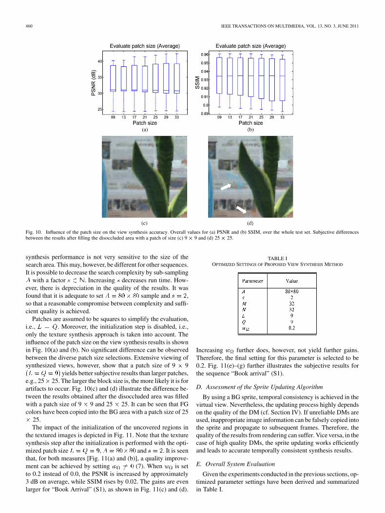
Fig. 10. Influence of the patch size on the view synthesis accuracy. Overall values for (a) PSNR and (b) SSIM, over the whole test set. Subjective differencesbetween the results after filling the disoccluded area with a patch of size (c) 9 � 9 and (d) 25 � 25.
synthesis performance is not very sensitive to the size of thesearch area. This may, however, be different for other sequences.It is possible to decrease the search complexity by sub-sampling
with a factor . Increasing decreases run time. How-ever, there is depreciation in the quality of the results. It wasfound that it is adequate to set sample and ,so that a reasonable compromise between complexity and suffi-cient quality is achieved.
Patches are assumed to be squares to simplify the evaluation,i.e., . Moreover, the initialization step is disabled, i.e.,only the texture synthesis approach is taken into account. Theinfluence of the patch size on the view synthesis results is shownin Fig. 10(a) and (b). No significant difference can be observedbetween the diverse patch size selections. Extensive viewing ofsynthesized views, however, show that a patch size of 9 9
yields better subjective results than larger patches,e.g., 25 25. The larger the block size is, the more likely it is forartifacts to occur. Fig. 10(c) and (d) illustrate the difference be-tween the results obtained after the disoccluded area was filledwith a patch size of 9 9 and 25 25. It can be seen that FGcolors have been copied into the BG area with a patch size of 25
25.The impact of the initialization of the uncovered regions in
the textured images is depicted in Fig. 11. Note that the texturesynthesis step after the initialization is performed with the opti-mized patch size , and . It is seenthat, for both measures [Fig. 11(a) and (b)], a quality improve-ment can be achieved by setting (7). When is setto 0.2 instead of 0.0, the PSNR is increased by approximately3 dB on average, while SSIM rises by 0.02. The gains are evenlarger for “Book Arrival” (S1), as shown in Fig. 11(c) and (d).
TABLE IOPTIMIZED SETTINGS OF PROPOSED VIEW SYNTHESIS METHOD
Increasing further does, however, not yield further gains.Therefore, the final setting for this parameter is selected to be0.2. Fig. 11(e)–(g) further illustrates the subjective results forthe sequence “Book arrival” (S1).
D. Assessment of the Sprite Updating Algorithm
By using a BG sprite, temporal consistency is achieved in thevirtual view. Nevertheless, the updating process highly dependson the quality of the DM (cf. Section IV). If unreliable DMs areused, inappropriate image information can be falsely copied intothe sprite and propagate to subsequent frames. Therefore, thequality of the results from rendering can suffer. Vice versa, in thecase of high quality DMs, the sprite updating works efficientlyand leads to accurate temporally consistent synthesis results.
E. Overall System Evaluation
Given the experiments conducted in the previous sections, op-timized parameter settings have been derived and summarizedin Table I.

NDJIKI-NYA et al.: DIBR WITH ADVANCED TEXTURE SYNTHESIS FOR 3-D VIDEO 461
TABLE IIPSNR AND SSIM RESULTS BY THE PROPOSED FRAMEWORK, THE VIEW SYNTHESIS REFERENCE SOFTWARE, AND FEHN
Fig. 11. Influence of the initialization step on the view synthesis accuracy.Overall values for (a) PSNR and (b) SSIM, for patch size of 9 � 9 over thewhole test set. The objective results for the sequence “Book arrival” with (c)PSNR and (d) SSIM. Result after filling the disoccluded area (e) without ini-tialization. (f) Result using the initialization step �� � ���� without texturesynthesis and (g) result using the initialization step �� � ���� before texturesynthesis.
The proposed approach is compared with the MPEG viewsynthesis reference software (VSRS, version 3.5) [32] with op-timized parameters and to the disocclusion elimination method
presented by Fehn [21]. In a rectified camera setup, the disocclu-sion elimination method fails to close holes on the left or rightimage border. Hence, the inpainting method introduced in [6] isused to fill these disocclusions. The achieved objective results,shown in Table II, are better than alternative approaches such ascropping and subsequently resizing the image.
In Table II the “camera” column (Cam.) represents the pro-jection configuration, i.e., “8 9” refers to the synthesis ofcamera 9 from camera 8. Note that the PSNR and SSIM values(quality measures) correspond to the mean over all pictures ofa sequence. The best result for each sequence is highlightedthrough bold face type. For the sequences “Book arrival” (S1),the proposed approach gives better SSIM and PSNR results thanVSRS and Fehn [21]. For the “Lovebird1” (S2) sequence our al-gorithm shows better SSIM results. For the PSNR value, MPEGVSRS performs better for the case “6 8” and “6 7”. Sub-jectively, in these cases the VSRS rendering is blurrier, while ourresults are sharper but noisier. For the sequence “Newspaper”(S3) VSRS achieves better overall results. As all our modulesrely on the DM and the DM of “Newspaper” (S3) is particularlyunreliable, visual and objective losses occur for the proposed al-gorithm. Nevertheless, some visual and objective gains can beobtained for the case “6 4” and “6 5” (see Table II andFig. 4(d)–(f); electronic magnification may be required). For thesequences “Mobile” (S4) characterized by a highly structuredBG, the proposed approach gives better SSIM and PSNR re-sults than VSRS and Fehn [21].
In addition to the objective measurements, Figs. 13 and 14show some subjective results. In Figs. 13 and 14(a), the orig-inal reference pictures 51 and 184 of the “Book arrival” (S1)and “Mobile” (S4) sequences are shown. In Fig. 14(b), the ren-dered images are shown [baseline extension, warping camera 8to the position of camera 10 (S1), warping camera 5 to the posi-tion of camera 3 (S4)]. The disoccluded areas are marked white(S1) or black (S4). In Fig. 14 (c) and (d), the final BG sprite andits associated DM are shown. The final rendering results by theproposed approach are shown in Fig. 14(e). The result by VSRS(S1) and Fehn [21] (S4) are shown in Fig. 14(f). Note that theproposed approach yields sharper edges than VSRS (Fig. 13)

462 IEEE TRANSACTIONS ON MULTIMEDIA, VOL. 13, NO. 3, JUNE 2011
Fig. 12. Evaluation of the run-time using different patch sizes.
and FG objects maintain their shape (Fig. 14). Fig. 14(g) and (h)shows magnifications of the squared areas in Fig. 14(e) and (f),where the results for the proposed algorithm are shown on theleft side and the results for VSRS on the right. FG informationis correctly omitted by our proposed filling method [Fig. 13(g)],which yields significantly improved synthesis results comparedto VSRS. As can be seen in Fig. 13(h) on the poster in the BG,details are again well preserved by our method. In Fig. 14(h)it can be seen that the algorithm proposed by Fehn [21] leadsto annoying distortions in the BG area and the FG objects. Theproposed method preserves the shape of the objects [Fig. 14(g)].The BG in “Mobile” (S4) is highly structured but even these dis-occlusions can be reconstructed satisfactorily with the proposedmethod. Fig. 14(i) and (j) shows the objective results. Gains areachieved in PSNR and SSIM.
F. Complexity Assessment
The complexity of the proposed algorithm is mainly domi-nated by the following three aspects:
1) the search area with the corresponding subsamplingfactor , of the texture synthesis approach;
2) the patch size used in the texture refinement step;3) the utilized cloning method used in the updating process.
The other functions are less time consuming and their contribu-tion to the overall complexity is rather small.
A PC with an Intel Xeon CPU and 4-GB RAM was usedin our experiments. Our software is currently implemented inMATLAB. The optimized settings given in Table I were used.
According to the results obtained, varying the search areaand the subsampling factor , strongly influences the complexityof the proposed approach. The complexity increases by a factorof approximately 1.5 when is doubled. On the other hand,when is increased from 1 to 2, the complexity reduces by afactor of approximately 1.31. Increasing from 1 to 4 yields acomplexity reduction of approximately 3.24.
To update the actual frame from the BG sprite, the co-variant cloning is used to fit the BG data into the frame (seeSection VII-B). For every sample position to be updated fromthe BG, a linear equation has to be solved. Hence, the com-plexity is proportional to the number of samples which arecopied from the BG sprite to the actual frame, which corre-sponds to linear growth of complexity.
Fig. 13. DIBR results for the “Book arrival” sequence. (a) Original referenceimage 51. (b) Rendered image with disoccluded area marked white. (c) FinalBG sprite with unknown area marked white and its associated DM (d). (e) Re-sult of picture 51 by the proposed approach. (f) Result of VSRS for the samepicture. (g), (h) Magnified results. Left: proposed approach. Right: VSRS. (i),(j) Objective results for all frames of the sequence.
Fig. 12 depicts the results obtained by varying the (square)patch size. Furthermore, the results are generated with the keyframes used in Section VII-C, i.e., the run time represents themean value of the different single images (no time consistencyis available) evaluated with the same patch size. It can be seenthat the complexity is approximately inversely proportional tothe patch size growth. This relates to the fact that larger patches

NDJIKI-NYA et al.: DIBR WITH ADVANCED TEXTURE SYNTHESIS FOR 3-D VIDEO 463
Fig. 14. DIBR results for the “Mobile” sequence. (a) Original reference image184. (b) Rendered image with disoccluded area marked black. (c) Final BGsprite with unknown area marked black and (d) its associated DM (unknown areamarked white). (e) Result of picture 184 by the proposed approach. (f) Result ofFehn [21] for the same picture. (g), (h) Magnified results. (g) Proposed approach.(h) Fehn [21]. (i), (j) Objective results for all frames of the sequence.
cover more unknown pixels. Hence, fewer search iterations haveto be run. If texture synthesis with time consistency (using spriteupdate) is applied with a patch of size 9 9, the run timedecreases by a factor of 3.2 compared to texture synthesiswithout time consistency (cf. Fig. 12). However, in applicationswhere complexity is of more importance than quality, a patchsize of 25 25 appears to be the better choice.
Note that the figure depicted here is rather useful for a relativethan for an absolute evaluation, as a hardware/C++ software im-plementation of the same approach will have different absolutecomplexity characteristics.
VIII. CONCLUSION AND FUTURE WORK
We have described a new hole-filling approach with in-painting methods for DIBR. The algorithm works for largebaseline extensions and generates spatio-temporally consistentrendering results. Each virtual view image featuring disocclu-sions is compensated using image information from a causalpicture neighborhood via a BG sprite. Residual uncovered areasare initially coarsely estimated and then refined using texturesynthesis. We have shown that the presented approach yieldssubjective and objective gains compared to state of the art viewsynthesis, given reasonable DM quality. However, depth esti-mation inconsistencies especially at foreground–backgroundtransitions may lead to considerable degradation of the ren-dering results. This dependency will therefore be reduced infuture work. Our examinations also showed that the lack ofan adequate perceptual measure for 3-D content, hampers afully optimized configuration of our view synthesis algorithm.Towards that end, extensive subjective experiments will becarried out in future work. Additionally, the problem of globaland local BG motion as well as complexity issues will beaddressed.
ACKNOWLEDGMENT
The authors would like to thank M. Müller and P. Kauff forbringing our attention to the usefulness of advanced synthesismethods in 3-D video. The authors would also like to thankthe Gwangju Institute of Science and Technology, Korea, theElectronic and Telecommunications Research Institute/MPEGKorea Forum, and Philips for providing the “Newspaper,”“Lovebird1,” and “Mobile” sequences, respectively.
REFERENCES
[1] O. Schreer, P. Kauff, and T. Sikora, 3D Video Communication: Algo-rithms, Concepts and Real-Time Systems in Human Centred Commu-nication. New York: Wiley, 2005.
[2] K.-J. Oh, S. Yea, and Y.-S. Ho, “Hole filling method using depthbased inpainting for view synthesis in free viewpoint television and3-D video,” in Proc. Picture Coding Symp., Chicago, IL, May 2009,pp. 233–236.
[3] C. L. Zitnik, S. B. Kang, M. Uyttendaele, S. Winder, and R. Szeliski,“High-quality video view interpolation using a layered representation,”in Proc. ACM SIGGRAPH, Los Angeles, CA, Aug. 2004, pp. 600–608.
[4] S. Zinger, L. Do, and P. H. N. de With, “Free-viewpoint depth imagebased rendering,” J. Vis. Commun. Image Representation, vol. 21, no.5–6, pp. 533–541, 2010.
[5] Y. Mori, N. Fukushima, T. Yendo, T. Fujii, and M. Tanimoto, “Viewgeneration with 3-D warping using depth information for FTV,” IEEEJ. Signal Process., vol. 24, no. 1–2, pp. 65–72, Jan.–Feb. 2009.
[6] A. Telea, “An image inpainting technique based on the fast marchingmethod,” Int. J. Graphic Tools, vol. 9, no. 1, pp. 25–36, 2004.
[7] M. Bertalmío, G. Sapiro, V. Caselles, and C. Ballester, “Image in-painting,” in Proc. ACM SIGGRAPH, New Orleans, LA, Jul. 2000, pp.417–424.
[8] K. Müller, A. Smolic, K. Dix, P. Merkle, P. Kauf, and T. Wiegand,“View synthesis for advanced 3-D video systems,” EURASIP J. ImageVideo Process., vol. 2008, 2008, Art. ID 438148.

464 IEEE TRANSACTIONS ON MULTIMEDIA, VOL. 13, NO. 3, JUNE 2011
[9] W. R. Mark, “Post-rendering 3-D image warping: Visibility, reconsruc-tion, and performance for depth-image warping,” Ph.D. dissertation,Graph. Image Process. Lab., Dept. Comput. Sci., Univ. North Carolina,Chapel Hill, 1999.
[10] X. Jiufei, X. Ming, L. Dongxiao, and Z. Ming, “A new virtual viewrendering method based on depth image,” in Proc. Asia–Pacific Conf.Wearable Computing Syst., Shenzhen, China, Apr. 2010, pp. 147–150.
[11] W.-Y. Chen, Y.-L. Chang, S.-F. Lin, L.-F. Ding, and L.-G. Chen, “Effi-cient depth image based rendering with edge dependent depth filter andinterpolation,” in Proc. IEEE Int. Conf. Multimedia Expo, Amsterdam,The Netherlands, Jul. 2005, pp. 1314–1317.
[12] L. Zhang and W. J. Tamm, “Stereoscopic image generation based ondepth images for 3-D TV,” IEEE Trans. Broadcasting, vol. 51, no. 2,pp. 191–199, Jun. 2005.
[13] P.-J. Lee and Effendi, “Adaptive edge-oriented depth image smoothingapproach for depth image based rendering,” in Proc. IEEE Int. Symp.Broadband Multimedia Syst. Broadcasting, Shanghai, China, Mar.2010, pp. 1–5.
[14] C.-M. Cheng, S.-J. Lin, S.-H. Lai, and J.-C. Yang, “Improved novelview synthesis from depth image with large baseline,” in Proc. IEEEInt. Conf. Pattern Recognit., Tampa, FL, Dec. 2008, pp. 1–4.
[15] M. Schmeing and X. Jiang, “Depth image based rendering: A faithfulapproach for the disocclusion problem,” in Proc. 3DTV-Conf.: TrueVision—Capture, Transmission and Display of 3-D Video, Tampere,Finland, Jun. 2010, pp. 1–4.
[16] K.-Y. Chen, P.-K. Tsung, P.-C. Lin, H.-J. Yang, and L.-G. Chen,“Hybrid motion/depth-oriented inpainting for virtual view synthesis inmultiview applications,” in Proc. 3DTV-Conf.: True Vision—Capture,Transmission and Display of 3-D Video, Tampere, Finland, Jun. 2010,pp. 1–4.
[17] Advanced Video Coding for Generic Audiovisual Services, ITU-T Rec.H.264 and ISO/IEC 14496-10 (MPEG4-AVC), v1, May 2003; v2, Jan.2004; v3 (with FRExt), Sep. 2004; v4, Jul. 2005.
[18] T. Wiegand, G. J. Sullivan, G. Bjontegaard, and A. Luthra, “Overviewof the H.264/AVC video coding standard,” IEEE Trans. Circuits Syst.Video Technol., vol. 13, no. 7, pp. 560–576, Jul. 2003.
[19] Z. Wang, A. C. Bovik, H. R. Sheikh, and E. P. Simoncelli, “Imagequality assessment: From error visibility to structural similarity,” IEEETrans. Image Process., vol. 13, no. 4, pp. 600–612, Apr. 2004.
[20] C.-M. Cheng, S.-J. Lin, S.-H. Lai, and J.-C. Yang, “Improved novelview synthesis from depth image with large baseline,” in Proc. Int.Conf. Pattern Recognit., Tampa, FL, Dec. 2008, pp. 1–4.
[21] C. Fehn, “Depth Image Based Rendering (DIBR), compression andtransmission for a new approach on 3D-TV,” in Proc. SPIE Stereo-scopic Disp. Virtual Reality Syst. XI, San Jose, CA, Jan. 2004, pp.93–104.
[22] A. Criminisi, P. Perez, and K. Toyama, “Region filling and object re-moval by exemplar-based inpainting,” IEEE Trans. Image Process.,vol. 13, no. 9, pp. 1200–1212, Sep. 2004.
[23] D. J. Heeger and J. R. Bergen, “Pyramid-based texture analysis/syn-thesis,” in Proc. ACM SIGGRAPH, Los Angeles, CA, 1995, pp.229–238.
[24] J. Portilla and E. P. Simoncelli, “A parametric texture model based onjoint statistics of complex wavelet coefficients,” Int. J. Comput. Vis.,vol. 40, no. 1, pp. 49–71, 2000.
[25] G. Doretto, A. Chiuso, Y. N. Wu, and S. Soatto, “Dynamic textures,”Int. J. Comput. Vis., pp. 91–109, Feb. 2004.
[26] J. Hayes and A. Efros, “Scene completion using millions of pho-tographs,” in Proc. ACM SIGGRAPH, San Diego, CA, Aug. 2007, pp.1–7.
[27] J. S. DeBonet, “Multiresolution sampling procedure for analysis andsynthesis of texture images,” in Proc. ACM SIGGRAPH, 1997, pp.361–368.
[28] M. Ashikhmin, “Synthesizing natural textures,” in Proc. ACM Symp.Interactive 3-D Graphics, New York, 2001, pp. 217–226.
[29] V. Kwatra, A. Schödl, I. Essa, G. Turk, and A. Bobick, “Graphcut tex-tures: Image and video synthesis using graph cuts,” in Proc. ACM SIG-GRAPH, San Diego, CA, Jul. 2003, pp. 277–286.
[30] P. Ndjiki-Nya, M. Köppel, D. Doshkov, and T. Wiegand, “Automaticstructure-aware inpainting for complex image content,” in Proc. Int.Symp. Visual Computing, Las Vegas, NV, Dec. 2009, pp. 1144–1156.
[31] M. Tanimoto, T. Fujii, and K. Suzuki, “Depth Estimation ReferenceSoftware (DERS) 5.0,” Lausanne, Switzerland, ISO/IEC JTC1/SC29/WG11 M16923, Oct. 2009.
[32] M. Tanimoto, T. Fujii, and K. Suzuki, “View Synthesis Algorithmin View Synthesis Reference Software 2.0 (VSRS 2.0),” Lausanne,Switzerland, ISO/IEC JTC1/SC29/WG11 M16090, Feb. 2008.
[33] C. M. Bishop, Neural Networks for Pattern Recognition. Oxford: Ox-ford Univ. Press, 1995.
[34] T. G. Georgiev, “Photoshop healing brush: A tool for seamlesscloning,” in Proc. Eur. Conf. Comput. Vis., Prague, Czech Republic,May 2004, pp. 1–8.
[35] T. G. Georgiev, “Covariant derivates and vision,” in Proc. Eur. Conf.Comput. Vis., Graz, Austria, 2006, pp. 56–69.
[36] P. Pérez, M. Gangnet, and A. Blake, “Poisson image editing,” in Proc.ACM SIGGRAPH, San Diego, CA, Jul. 2003, pp. 313–318.
[37] H. Lakshman, M. Köppel, P. Ndjiki-Nya, and T. Wiegand, “Image re-covery using sparse reconstruction based texture refinement,” in Proc.IEEE Int. Conf. Acoust. Speech Signal Process., Dallas, TX, Mar. 2010,pp. 786–789.
[38] J. Sun, L. Yuan, J. Jia, and H.-Y. Shum, “Image completion with struc-ture propagation,” in Proc. ACM SIGGRAPH, Los Angeles, CA, Aug.2005, pp. 861–868.
Patrick Ndjiki-Nya (M’98) received the Dipl.-Ing.title (corr. to M.S degree) and the Ph.D. degree fromthe Technical University of Berlin, Berlin, Germany,in 1997 and 2008, respectively.
He has developed an efficient method for content-based video coding, which combines signal theorywith computer graphics and vision. His approachesare currently being evaluated in equal or similar formby various companies and research institutions in Eu-rope and beyond. From 1997 to 1998, he was sig-nificantly involved with the development of a flight
simulation software at Daimler-Benz AG. From 1998 to 2001, he was a Devel-opment Engineer with DSPecialists GmbH, where he was concerned with theimplementation of algorithms for digital signal processors (DSPs). During thesame period, he researched content-based image and video features with theFraunhofer Institute for Telecommunications—Heinrich Hertz Institute, Berlin,Germany, with the purpose of implementation in DSP solutions from DSPescial-ists GmbH. Since 2001, he has been with the Fraunhofer Heinrich Hertz Institutesolely, where he was Project Manager initially and Senior Project Manager from2004 on. He has been Group Manager since 2010.
Martin Köppel received the Dipl.-Ing. degree inmedia technologies from the Technical University ofIlmenau, Ilmenau, Germany, in 2008.
Before then, he was a Student Engineer with the In-stitut of Microelectronic- and Mechatronic SystemsgGmbH, Ilmenau, Germany, from 2004 to 2006. Hewas a Teaching Assistant with the Technical Univer-sity of Ilmenau from 2006 to 2007. He joined theFraunhofer Institute for Telecommunications—Hein-rich Hertz Institute, Berlin, Germany, in 2007, andhas been working there as a Research Associate since
2008. His research interests are in the fields of image and video processing. Hehas been involved in several projects in the areas of texture synthesis, view syn-thesis, video coding, and 3-D video.
Dimitar Doshkov received the Dipl.-Ing. degree intelecommunication engineering from the Universityof Applied Sciences of Berlin, Berlin, Germany, in2008.
He was with miControl Parma & Woijcik OHGfrom 2004 to 2005. In 2006, he joined SamsungSDI Germany GmbH as a Trainee. He has beenwith the Fraunhofer Institute for Telecommunica-tions—Heinrich Hertz Institute, Berlin, Germany,since 2007, where he has been a Research Associatesince 2008. His research interests include image
and video processing, as well as computer vision and graphics. He has beeninvolved in several projects focused on image and video synthesis, videocoding, and 3-D video.
NDJIKI-NYA et al.: DIBR WITH ADVANCED TEXTURE SYNTHESIS FOR 3-D VIDEO 465
Haricharan Lakshman received the B.E. degreefrom the National Institute of Technology Karnataka,Karnataka, India, in 2002, and the M.S. degree inelectrical engineering from the University of Er-langen-Nuremberg, Erlangen, Germany, in 2008.
From 2002 to 2005, he was an Engineer withIttiam Systems, India. From 2005 to 2006, he waswith the Audio Group of the Fraunhofer-Institute forIntegrated Circuits, Erlangen, Germany. In 2008, hejoined the Fraunhofer Institute for Telecommunica-tions—Heinrich Hertz Institute, Berlin, Germany, as
a Research Associate. His research interests include image and video codingand postprocessing.
Philipp Merkle (S’06) received the Dipl.-Ing. degreein electrical engineering from the Technical Univer-sity of Berlin, Berlin, Germany, in 2006.
He joined the Fraunhofer Institute for Telecom-munications—Heinrich Hertz Institute, Berlin,Germany, in 2003, where he has been as a Re-search Associate since 2006. He has been involvedin several projects focused on multiview videocoding, 3-D television, free viewpoint video, and3-D scene reconstruction. His research interestsinclude 3-D video, representation and compression
of multiview-video-plus-depth scenes, free viewpoint video, and 2-D and 3-Dvideo-based rendering. He has been involved in ISO standardization activitieswhere he contributed to the development of the MPEG-4 multiview videocoding standard.
Mr. Merkle was the recipient of the “Rudolf-Urtel Award” of the GermanSociety for Technology in TV and Cinema (FKTG) for his work on multiviewvideo coding in 2006.
Karsten Müller (M’98–SM’07) received the Dipl.-Ing. degree and the Dr.-Ing. degree in electrical en-gineering from the Technical University of Berlin,Berlin, Germany, in 1997 and 2006, respectively.
He has been with the Fraunhofer Institute forTelecommunications—Heinrich Hertz Institute,Berlin, Germany, since 1997, where he is currentlyProject Manager for 3-D video projects. His researchinterests are mainly in the field of representation,coding, and reconstruction of 3-D scenes in freeviewpoint video scenarios and coding, multiview ap-
plications and combined 2-D/3-D similarity analysis. He has been involved withMPEG standardization activities in 3-D video coding and content description.
Thomas Wiegand (M’05–SM’08–F’11) receivedthe Dipl.-Ing. degree in electrical engineering fromthe Technical University of Hamburg-Harburg,Hamburg, Germany, in 1995, and the Dr.-Ing.degree from the University of Erlangen-Nuremberg,Erlangen, Germany, in 2000.
He is a Professor with the Department of ElectricalEngineering and Computer Science, Berlin Instituteof Technology, Berlin, Germany, chairing the ImageCommunication Laboratory, and is jointly headingthe Image Processing Department, Fraunhofer Insti-
tute for Telecommunications—Heinrich Hertz Institute, Berlin. He joined theHeinrich Hertz Institute in 2000 as the head of the Image Communication Groupin the Image Processing Department. His research interests include video pro-cessing and coding, multimedia transmission, as well as computer vision andgraphics. From 1993 to 1994, he was a Visiting Researcher with Kobe Univer-sity, Japan. In 1995, he was a Visiting Scholar with the University of Californiaat Santa Barbara. From 1997 to 1998, he was a Visiting Researcher with Stan-ford University and served as a consultant to 8� 8, Inc., Santa Clara, CA. From2006 to 2008, he was a Consultant to Stream Processors, Inc., Sunnyvale, CA.From 2007 to 2009, he was a Consultant to Skyfire, Inc., Mountain View, CA.Since 2006, he has been a Member of the Technical Advisory Board of Vidyo,Inc., Hackensack, NJ. Since 1995, he has been an active participant in standard-ization for multimedia with successful submissions to ITU-T VCEG, ISO/IECMPEG, 3GPP, DVB, and IETF. In October 2000, he was appointed as the As-sociated Rapporteur of ITU-T VCEG. In December 2001, he was appointed asthe Associated Rapporteur/Co-Chair of the JVT. In February 2002, he was ap-pointed as the Editor of the H.264/MPEG-4 AVC video coding standard andits extensions (FRExt and SVC). From 2005–2009, he was Co-Chair of MPEGVideo.
Prof. Wiegand was the recipient of the SPIE VCIP Best Student Paper Awardin 1998 and the Fraunhofer Award and the ITG Award of the German Societyfor Information Technology in 2004. The projects that he co-chaired for de-velopment of the H.264/MPEG-4 AVC standard have been recognized by the2008 ATAS Primetime Emmy Engineering Award and a pair of NATAS Tech-nology & Engineering Emmy Awards. In 2009, he was the recipient of the In-novations Award of the Vodafone Foundation, the EURASIP Group TechnicalAchievement Award, and the Best Paper Award of the IEEE TRANSACTIONS
ON CIRCUITS AND SYSTEMS FOR VIDEO TECHNOLOGY. In 2010, he was the re-cipient of the Eduard Rhein Technology Award. He was a guest editor for theIEEE TRANSACTIONS ON CIRCUITS AND SYSTEMS FOR VIDEO TECHNOLOGY
for its Special Issue on the H.264/AVC Video Coding Standard in July 2003,its Special Issue on Scalable Video Coding—Standardization and Beyond inSeptember 2007, and its Special Section on the Call for Proposal on High-Ef-ficiency Video Coding in December 2010. Since January 2006, he has been anassociate editor of the IEEE TRANSACTIONS ON CIRCUITS AND SYSTEMS FOR
VIDEO TECHNOLOGY.