ieee transactions on power delivery 1 circulating current
TRANSCRIPT

This article has been accepted for inclusion in a future issue of this journal. Content is final as presented, with the exception of pagination.
IEEE TRANSACTIONS ON POWER DELIVERY 1
Circulating Current Control in MMCUnder the Unbalanced Voltage
Ji-Woo Moon, Student Member, IEEE, Chun-Sung Kim, Student Member, IEEE, Jung-Woo Park,Dae-Wook Kang, Member, IEEE, and Jang-Mok Kim, Member, IEEE
Abstract—This paper proposes a control method for circulatingcurrents in modular multilevel converters (MMCs) under un-balanced voltage conditions. Under balanced voltage conditions,only negative-sequence circulating currents exist. Consequently,the conventional method has considered only negative-sequencecirculating currents in MMC. However, under unbalanced voltageconditions, there are positive-sequence circulating currents,zero-sequence circulating currents, and negative-sequence cir-culating currents in MMC. Thus, under unbalanced voltageconditions, a control method should consider all of these compo-nents. This study adopts a dual vector current controller as anac-side current controller to reduce the ac-side active power rippleunder unbalanced voltage. It analyzes the effect of the unbalancedvoltage on circulating currents in MMC and then proposes a con-trol method considering each component of circulating currentsunder the unbalanced voltage. The effectiveness of the proposedcontrolling method is verified through simulation results usingPSCAD/EMTDC.
Index Terms—Circulating current, dual vector current control(DVCC),modularmultilevel converter (MMC), negative sequence,positive sequence, zero sequence.
I. INTRODUCTION
C URRENTLY, the number of investments and studieshave increased for high-voltage direct-current (HVDC)
transmission systems to enhance the efficiency and reliability ofac networks, which have applications for high-capacity electricpower transmission and provide links between different powergrids, such as China’s large-scale HVDC Investment Plan,the European Super Grid, and North America’s 2030 Project.
Manuscript received January 14, 2013; revised April 01, 2013; accepted May16, 2013. Paper no. TPWRD-00061-2013.J.-W. Moon is with the Department of Electrical Engineering, Pusan Na-
tional University, Pusan 609-735, Korea, and also with the Power Conversionand Control Research Center, Korea Electrotechnology Research institute,Changwon 642-120, Korea (e-mail: [email protected]).C.-S. Kim is with the Department of Electrical Engineering, Chunnam Na-
tional University, Chunnam 500-757, Korea and also with the Power Conver-sion and Control Research Center, Korea Electrotechnology Research Institute,Changwon 642-120, Korea (e-mail: [email protected]).J.-W. Park and D.-W. Kang are with the Power Conversion and Control Re-
search Center, Korea Electrotechnology Research Institute, Changwon 642-120,Korea (e-mail: [email protected]; [email protected]).J.-M. Kim is with the Department of Electrical Engineering, Pusan National
University, Pusan 609-735, Korea (e-mail: [email protected]).Color versions of one or more of the figures in this paper are available online
at http://ieeexplore.ieee.org.Digital Object Identifier 10.1109/TPWRD.2013.2264496
HVDC systems can be divided into two converter types: cur-rent-source converter HVDC (CSC-HVDC) and voltage-sourceconverter HVDC (VSC-HVDC). The interest in VSC-HVDCsystems is increasing because of the need for active control forrenewable energy systems and stabilization for electrical powersystems [1], [2]. Compared to CSC-HVDC, VSC-HVDC hasthe advantages of being able to control active power and reac-tive power independently, reduce the size of grid-side ac filters,and improve the transient response characteristics by using thePWM method. This system also has no need for a transformerto assist in the commutation process [3].The multilevel converters applied to VSC–HVDC are di-
vided into three types: 1) diode-clamped multilevel converter(DCMC), 2) flying capacitor multilevel converter (FCMC), and3) modular multilevel converter (MMC). Among them, DCMCand FCMC have been applied to a limited extent because ofthe difficulty in modularization and the need for additionalclamping diodes and flying capacitors [4]. In contrast, MMCshave the merits of extendibility to hundreds of voltage levelsbecause of their simple circuit structure and easy modulariza-tion despite the need for a reactor to suppress the circulatingcurrent. Consequently, MMCs are the most suitable structuresfor obtaining high dc voltage, and many studies have beencarried out on them [5]–[15].MMCs were first proposed in [16]. Fig. 1 shows the struc-
ture of a three-phase MMC with six arms. Each arm is com-posed of a series of connected half-bridge submodules (SMs).An MMC possesses a voltage difference between a dc link andeach arm with SMs, which leads to a problem of circulating cur-rents in each arm. References [17] and [18] analyzed the ampli-tude of circulating currents according to the arm inductance andthe SM’s capacitance. As the arm inductance increases, the am-plitude of the circulating currents decreases. However, despitethe increase in arm inductance, circulating currents are not re-duced completely, which is inefficient in terms of the cost-ben-efit analysis. Thus, a control method for circulating currents isnecessary.Reference [19] proposed a method of controlling an MMC’s
circulating currents. Under the balanced voltage condition, thenegative-sequence component of circulating currents in eacharm rotates at the double-line frequency. Therefore, a controlmethod was proposed that controlled circulating currents ineach arm frame by transforming an a-c-b sequence with adouble line-frequency into a – sequence at the rotationalreference frame. However, this method has the disadvantage ofnot being able to completely reduce circulating currents underunbalanced voltage conditions, because circulating currents
0885-8977/$31.00 © 2013 IEEE

This article has been accepted for inclusion in a future issue of this journal. Content is final as presented, with the exception of pagination.
2 IEEE TRANSACTIONS ON POWER DELIVERY
Fig. 1. Basic structure of MMC.
Fig. 2. Positive-sequence and negative-sequence inner current controller.
have also positive-sequence components and zero-sequencecomponents besides negative-sequence components.Reference [2] proposed a control method for MMC under
unbalanced voltage conditions. It analyzed the instantaneouspower of each arm under unbalanced voltage conditions andproposed a control algorithm for reducing circulating currentsand dc-link voltage ripples. However, this algorithm has the dis-advantage of the inclusion of a double-line-frequency ripple inac-side active power by controlling ac-side negative-sequencecurrents to zero under unbalanced voltage conditions.Reference [20] proposed a control method for circulating cur-
rents in an a-b-c stationary frame. Since circulating currentshave positive-, negative-, and zero-sequence components underunbalanced voltage conditions, a control method for circulatingcurrents was proposed by considering these components. How-ever, this method has the disadvantage of generating a phasedelay because of its utilization of a high-pass filter to separatecirculating currents; further, it cannot improve the transient re-sponse occurring in the inner unbalanced currents and dc-linkcurrents under unbalanced voltage conditions.Reference [6] proposed an MMC control method using
model predictive control (MPC). The authors organized the
Fig. 3. Single-phase equivalent circuit of the three-phase MMC.
Fig. 4. Generalized equivalent circuit diagram of the MMC under unbalancedconditions.
Fig. 5. Proposed circulating currents control scheme.
cost function to control ac-side currents, circulating currents,and SM voltage balancing using the MPC method and detectedthe switch status to minimize the cost function. However, thismethod has a disadvantage in the calculation volume of theprocessor, which increases with an increase in the level of theMMC because it should decide the switching status withwhen the MMC is at the level.This study analyzed each phase’s instantaneous power to
reduce the MMC’s ac-side active power ripple when the neg-ative-sequence component was generated under unbalancedvoltage conditions. The instantaneous power begins to have
This article has been accepted for inclusion in a future issue of this journal. Content is final as presented, with the exception of pagination.
MOON et al.: CIRCULATING CURRENT CONTROL IN MMC UNDER THE UNBALANCED VOLTAGE 3
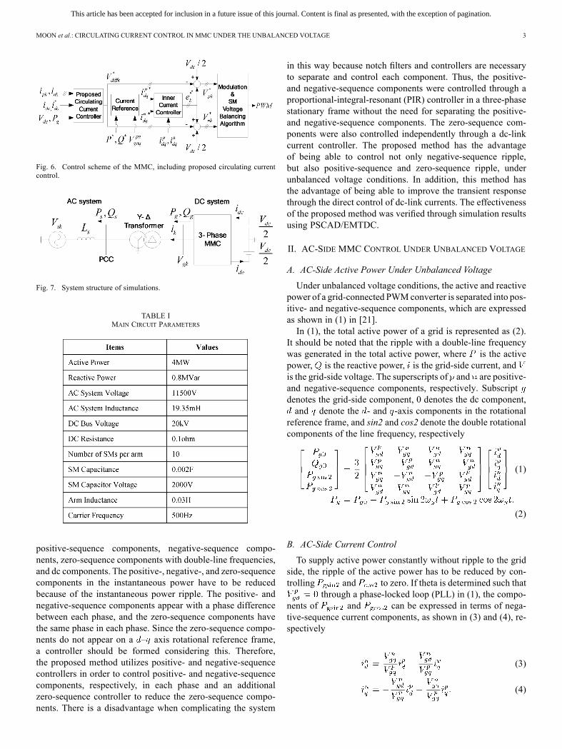
Fig. 6. Control scheme of the MMC, including proposed circulating currentcontrol.
Fig. 7. System structure of simulations.
TABLE IMAIN CIRCUIT PARAMETERS
positive-sequence components, negative-sequence compo-nents, zero-sequence components with double-line frequencies,and dc components. The positive-, negative-, and zero-sequencecomponents in the instantaneous power have to be reducedbecause of the instantaneous power ripple. The positive- andnegative-sequence components appear with a phase differencebetween each phase, and the zero-sequence components havethe same phase in each phase. Since the zero-sequence compo-nents do not appear on a – axis rotational reference frame,a controller should be formed considering this. Therefore,the proposed method utilizes positive- and negative-sequencecontrollers in order to control positive- and negative-sequencecomponents, respectively, in each phase and an additionalzero-sequence controller to reduce the zero-sequence compo-nents. There is a disadvantage when complicating the system
in this way because notch filters and controllers are necessaryto separate and control each component. Thus, the positive-and negative-sequence components were controlled through aproportional-integral-resonant (PIR) controller in a three-phasestationary frame without the need for separating the positive-and negative-sequence components. The zero-sequence com-ponents were also controlled independently through a dc-linkcurrent controller. The proposed method has the advantageof being able to control not only negative-sequence ripple,but also positive-sequence and zero-sequence ripple, underunbalanced voltage conditions. In addition, this method hasthe advantage of being able to improve the transient responsethrough the direct control of dc-link currents. The effectivenessof the proposed method was verified through simulation resultsusing PSCAD/EMTDC.
II. AC-SIDE MMC CONTROL UNDER UNBALANCED VOLTAGE
A. AC-Side Active Power Under Unbalanced Voltage
Under unbalanced voltage conditions, the active and reactivepower of a grid-connected PWMconverter is separated into pos-itive- and negative-sequence components, which are expressedas shown in (1) in [21].In (1), the total active power of a grid is represented as (2).
It should be noted that the ripple with a double-line frequencywas generated in the total active power, where is the activepower, is the reactive power, is the grid-side current, andis the grid-side voltage. The superscripts of and are positive-and negative-sequence components, respectively. Subscriptdenotes the grid-side component, 0 denotes the dc component,and denote the - and -axis components in the rotational
reference frame, and sin2 and cos2 denote the double rotationalcomponents of the line frequency, respectively
(1)
(2)
B. AC-Side Current Control
To supply active power constantly without ripple to the gridside, the ripple of the active power has to be reduced by con-trolling and to zero. If theta is determined such that
through a phase-locked loop (PLL) in (1), the compo-nents of and can be expressed in terms of nega-tive-sequence current components, as shown in (3) and (4), re-spectively
(3)
(4)
This article has been accepted for inclusion in a future issue of this journal. Content is final as presented, with the exception of pagination.
4 IEEE TRANSACTIONS ON POWER DELIVERY
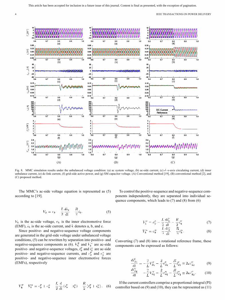
Fig. 8. MMC simulation results under the unbalanced voltage condition: (a) ac system voltage, (b) ac-side current, (c) – -axis circulating current, (d) innerunbalance current, (e) dc-link current, (f) grid-side active power, and (g) SM capacitor voltage. (A) Conventional method [19], (B) conventional method [2], and(C) proposed method.
The MMC’s ac-side voltage equation is represented as (5)according to [19].
(5)
is the ac-side voltage, is the inner electromotive force(EMF), is the ac-side current, and denotes a, b, and c.Since positive- and negative-sequence voltage components
are generated in the grid-side voltage under unbalanced voltageconditions, (5) can be rewritten by separation into positive- andnegative-sequence components as (6). and are ac-sidepositive- and negative-sequence voltages, and are ac-sidepositive- and negative-sequence currents, and and arepositive- and negative-sequence inner electromotive forces(EMFs), respectively
(6)
To control the positive-sequence and negative-sequence com-ponents independently, they are separated into individual se-quence components, which leads to (7) and (8) from (6)
(7)
(8)
Converting (7) and (8) into a rotational reference frame, thesecomponents can be expressed as follows:
(9)
(10)
If the current controllers comprise a proportional-integral (PI)controller based on (9) and (10), they can be represented as (11)
This article has been accepted for inclusion in a future issue of this journal. Content is final as presented, with the exception of pagination.
MOON et al.: CIRCULATING CURRENT CONTROL IN MMC UNDER THE UNBALANCED VOLTAGE 5
and (12). Fig. 2 shows the block diagram of the positive-se-quence and negative-sequence current controllers
(11)
(12)
where is the positive-sequence inner emf reference in the– axis and is the negative-sequence inner emf referencein the – axis.
III. CIRCULATING CURRENT CONTROL
A. Phase Instantaneous Power Under Unbalanced Voltage
In an MMC, circulating currents are caused by variations inthe total SM capacitor voltage in each arm. Under balancedvoltage conditions, circulating currents are double-line fre-quency components that rotate at a negative sequence [1], [2],[19].Fig. 3 shows a single-phase equivalent circuit in a three-phase
MMC system. Here, is the inner unbalance current, andare the upper and lower arms’ currents, is phase ’s inner
emf, and and are the upper and lower arm voltages,respectively.According to Fig. 3, the MMC’s voltage equation is given by
[19], where is the inner unbalance voltage of phase .
(13)
The EMF is expressed as follows:
(14)
An inner unbalance current is expressed as (15),where is the inner unbalance current’s dc component, andis the inner unbalance current’s ac component, which is the
circulating current component
(15)
Under unbalanced voltage conditions, the MMC’s ac-sidecurrent controller injects the negative-sequence current foractive power-ripple reduction. Consequently, emf containsboth positive- and negative-sequence components. Thus, theMMC’s upper arm voltage and lower arm voltage areexpressed as (16) and (17), respectively
(16)
(17)
where is the compensation value of the MMC innerunbalance voltage.In addition, the upper arm current and lower arm current are
given by (18) and (19), respectively
(18)
(19)
Each phase’s instantaneous power is expressed as (20).is defined in the Appendix, which is briefly summarized
as
(20)
(21)
where is the dc component, is the positive-sequencedouble-line frequency component, is the negative-se-quence double-line frequency component, is the zero-se-quence double-line frequency component, and is thecompensation value of the MMC inner unbalanced voltagecomponent.Thus, each phase’s instantaneous power consists not only
of negative-sequence double-line frequency components, butalso positive- and zero-sequence double-line frequency com-ponents. Consequently, to eliminate the instantaneous powerripple, a negative-sequence double-line frequency controlleras well as positive- and zero-sequence double-line frequencycontrollers are necessary. The equivalent circuit is shown inFig. 4. where
and .
B. Circulating Current Control Under Unbalanced Voltage
In (21), is the magnitude of the inner EMF and inner unbal-anced current. The inner EMF is determined by the ac-side cur-rents controller. Thus, to reduce the instantaneous power ripple,the inner unbalanced current ripple component should be re-duced. The inner unbalance current is briefly defined
(22)
where is the positive-sequence inner unbalanced currentdouble-line frequency, is the negative-sequence inner un-balance current double-line frequency, is the zero-sequenceinner unbalance current double-line frequency, is the dccomponent current, and .The inner unbalanced current’s ac component is the cir-
culating current, which should be controlled to zero. However,to control each component like a dual vector current controller(DVCC), the notch filter and PI controller are necessary. Conse-quently, the controller’s structure is complicated. Thus, to con-trol each component simultaneously, a controller is constructedin a three-phase stationary frame using a PIR controller.This has the advantage of being able to control each compo-
nent without decomposition into separate components. Underbalanced voltage conditions, the inner unbalanced currentflowing in each phase should be controlled as . In addi-tion, under unbalanced voltage conditions, the ac-side activepower ripple is controlled to zero by the DVCC. This meansthat each phase’s active power has the same magnitude. Con-sequently, the inner unbalanced current flowing in each phaseshould be controlled to . Thus, the circulating currentcontroller is constructed as shown in (23). Since only thedouble-line frequency of the inner unbalance current’s ripple
This article has been accepted for inclusion in a future issue of this journal. Content is final as presented, with the exception of pagination.
6 IEEE TRANSACTIONS ON POWER DELIVERY
component exists, the resonant controller’s cutoff frequency isset to the double-line frequency
(23)
where is defined as the sum of each phase’s inner unbal-ance current. In a three-phase system, the sum of positive-se-quence and negative-sequence current should be zero. Thus, idcis briefly expressed as (24), where is anda dc component
(24)
For inner unbalanced current control, the current referenceis applied to . Thus, the current reference includes thezero-sequence component ripple. Thus, with the PIR controller,the positive-sequence and negative-sequence component rip-ples can be reduced. However, the zero-sequence componentripple is not reduced. Thus, a controller to reduce this ripplecomponent is necessary.If it is assumed that there is no loss in the MMC, the MMC’s
ac-side active power and dc-side active power should beequivalent. Under unbalanced voltage conditions, because theac-side active power ripple is reduced through the DVCC, theac-side active power has no ripple. The dc-side active poweris given as (25). The ac-side active power and dc-link voltageare known, so the dc-link current reference is obtainable. Thedc-link current reference does not contain positive, negative, norzero sequences. Thus, the dc-link current reference can be ap-plied to reduce the current ripples from the zero-sequence com-ponent. A controller to reduce the ripple component from thezero sequence can be constructed as shown in (27), and the con-trol output value to control each component is defined in (28).The dc-link current controller has a characteristic that allows itto control the zero-sequence current ripple as well as providingit with a fast transient response under unbalanced voltage con-ditions. Fig. 5 shows a block diagram of the proposed circu-lating current control. It consists of three PIR controllers to con-trol the positive- and negative-sequence circulating currents andone PIR controller to reduce the zero-sequence circulating cur-rent and dc current ripple. Fig. 6 shows a control scheme of theMMC that includes the proposed circulating current control
(25)
(26)
(27)
(28)
IV. SIMULATION RESULTS
Simulation was carried out using PSCAD/EMTDC, andFig. 7 shows the structure of the simulated system. The maincircuit parameters and operating conditions are listed in Table I.The PWM method and SM’s capacitor voltage-balancing algo-rithm uses the PSC–PWM method from [19].Fig. 8 shows the simulation results of a conventional circu-
lating current control method [19], a control method consideringunbalanced voltage conditions [2], and the proposed circulating
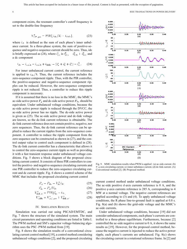
Fig. 9. MMC simulation results when PWM is applied : (a) ac-side current. (b)– axis circulating current, (c) inner unbalance current, (d) dc-link current. (A)Conventional method [2]. (B) Proposed method.
current control method under unbalanced voltage conditions.The ac-side positive -axis currents reference is 0 A, and thepositive -axis currents reference is 285 A, corresponding to 4MW at a normal voltage. The negative current references areapplied according to (3) and (4). To apply unbalanced voltageconditions, the R phase line-to-ground fault is applied at 0.8 s.Fig. 8(a) and (b) shows the grid-side voltage and the MMC’sac-side currents.Under unbalanced voltage conditions, because [19] did not
consider unbalanced components, each phase’s currents are con-trolled to a three-phase equilibrium. Furthermore, because [2]controlled the ac-side negative current to 0 A, it shows the sameresults as [19]. However, for the proposed control method, be-cause the negative current is injected to reduce the active powerripple, each phase’s currents are unbalanced. Fig. 8(c) showsthe circulating current in a rotational reference frame. In [2] and

This article has been accepted for inclusion in a future issue of this journal. Content is final as presented, with the exception of pagination.
MOON et al.: CIRCULATING CURRENT CONTROL IN MMC UNDER THE UNBALANCED VOLTAGE 7
[19], the circulating current ripple is increased under unbalancedvoltage conditions. However, the proposed control method con-siders components under unbalanced voltage conditions; thus,the circulating current ripple is reduced compared to that in con-ventional methods. However, in Fig. 8(d) and (e), each phase’sinner unbalanced current and dc-link currents have severe ripplewith transient currents due to ac-side active power ripple be-cause there is an unbalanced voltage supply. Reference [19]does not control the dc-link ripple component caused by un-balanced voltage; a double-line frequency ripple is generated aswell as a dc-link transient current.Reference [2] reduced the double-line frequency ripple
through a resonant controller in the dc-link component, so thereis no unbalanced ripple component. However, because only aresonant controller is used, it is unable to reduce the dc-linkcurrent ripple due to the transient status. In the proposed controlmethod, the dc-link current is directly controlled, so the dc-linkcurrent is stably controlled without transient characteristics,even through an unbalanced voltage is applied.Fig. 8(f) shows the MMC’s ac-side active power. In [2] and
[19], the MMC’s ac-side active power ripple cannot be reduced,so the double-line frequency ripple is generated under activepower. In the proposed control method, a negative current isinjected to reduce the active power ripple, so the active powerripple caused by unbalanced voltage conditions is reduced.However, the magnitude of the active power is reduced by anegative sequence’s active power component. Fig. 8(g) showsthe SM’s capacitor voltage. The SM’s capacitor voltage bal-ancing is stably controlled because the same voltage-balancingmethod is used.Fig. 9 shows the characteristics of the ac-side currents, circu-
lating current, and dc-link current when PWM is applied. WhenPWM is applied, the ac-side currents are controlled at 0 A. Inac-side currents, the conventional control method and the pro-posed control method show similar characteristics. However, inthe conventional control method, the dc-link transient current isnot only controlled because of the controlling double-line fre-quency ripple. However, the proposed control method showsstable characteristics without ripple in the dc-link currents be-cause the dc-link transient current is controlled when PWM isapplied.
V. CONCLUSION
This paper proposed a control method for MMCs under un-balanced voltage conditions. To reduce ac-side active powerripple under unbalanced voltage conditions, ac-side componentsare decomposed into positive- and negative-sequence compo-nents. In addition, a DVCC is designed to control the ac-sidepositive and negative currents. Furthermore, the dc-side instan-taneous power ripple is analyzed by ac-side positive- and neg-ative-sequence components. Based on the analysis, a controlleris designed to control the double-line frequency positive-, neg-ative-, and zero-sequence components. The proposed controlmethod can stably control circulating currents and the dc-linkcurrent even under unbalanced voltage conditions. In addition,the transient response is improved.
APPENDIX
The voltages of the phases of the upper arm and lower armare given in (A1) and (A2), where
and are the phase anglesof the positive- and negative-sequence inner emfs, respectively
(A1)
(A2)
Each arm’s currents in (18) and (19) are also expressed as posi-tive and negative sequences, respectively
(A3)
(A4)
where is the positive-sequence current modulation index,is the negative-sequence modulation index, and and
are the positive- and negative-phase angles of the converter acoutput current, respectively.Substituting (A1)–(A4) into (20), each phase’s instantaneous
power is given as
(A5)
where
Equation (A5) is separated into individual components anddefined as follows:Item 1) dc component and regulating the unbalanced voltage;Item 2) double-line frequency negative sequence;Item 3) double-line frequency positive sequence;Item 4) double-line frequency zero sequence.Thus, under unbalanced voltage conditions, to reduce the
ac-side active power ripple from the MMC, if there is a neg-ative-sequence component in the ac side, each phase’s powerdoes not have only the dc component and the negative-sequence

This article has been accepted for inclusion in a future issue of this journal. Content is final as presented, with the exception of pagination.
8 IEEE TRANSACTIONS ON POWER DELIVERY
double-line frequency component, but also positive-sequenceand zero-sequence double-line frequency components.Here, because the positive sequence, negative sequence, and
zero sequence are active power-ripple components, they shouldbe controlled to 0 through .
REFERENCES
[1] A. Antonopoulos, L. Angquist, and H. P. Nee, “On dynamics andvoltage control of the modular multilevel converter,” in Proc. Eur.Conf. Power Electron. Appl., Barcelona, Spain, 2009, pp. 1–10.
[2] Q. Tu, Z. Xu, Y. Chang, and L. Guan, “Suppressing DC voltage rip-ples of MMC-HVDC under unbalanced grid conditions,” IEEE Trans.Power Del., vol. 27, no. 3, pp. 1332–1338, Jul. 2012.
[3] N. Flourentzou, V. G. Agelidis, and G. D. Demetriades, “VSC-basedHVDC power transmission systems: An overview,” IEEE Trans.Power Electron., vol. 24, no. 3, pp. 592–602, Mar. 2009.
[4] Y. H. Liu, J. Arrillaga, and N. R. Watson, “Cascaded H-bridge voltagereinjection—Part I: A new concept in multilevel voltage-source con-version,” IEEE Trans. Power Del., vol. 23, no. 2, pp. 1175–1182, Apr.2008.
[5] Q. Tu and Z. Xu, “Impact of sampling frequency on harmonic distortionformodular multilevel converter,” IEEE Trans. Power Del., vol. 26, no.1, pp. 298–306, Jan. 2011.
[6] J. Qin and M. Saeedifard, “Predictive control of a modular multilevelconverter for a back-to-back HVDC system,” IEEE Trans. Power Del.,vol. 27, no. 3, pp. 1538–1547, Jul. 2012.
[7] B. Andersen, L. Xu, P. J. Horton, and P. Cartwright, “Topologies forVSC transmission,” Power Eng. J., vol. 16, no. 3, pp. 142–150, Jun.2002.
[8] M. Saeedifard, R. Iravani, and J. Pou, “A space vector modulationstrategy for a back-to-back five-level HVDC converter system,” IEEETrans. Ind. Electron., vol. 56, no. 2, pp. 452–466, Feb. 2009.
[9] S. Li, T. Haskew, and L. Xu, “Control of HVDC light system using con-ventional and direct current vector control approaches,” IEEE Trans.Power Electron., vol. 25, no. 12, pp. 3106–3118, Dec. 2010.
[10] A. Lesnicar and R. Marquardt, “A newmodular voltage source invertertopology,” presented at the 10th Eur. Conf. Power Electron. Appl.,Toulouse, France, 2003.
[11] M. Saeedifard and R. Iravani, “Dynamic performance of a modularmultilevel back-to-back HVDC system,” IEEE Trans. Power Del., vol.25, no. 4, pp. 2903–2912, Oct. 2010.
[12] S. Rohner, S. Bernet, M. Hiller, and R. Sommer, “Modelling, simula-tion and analysis of a modular multilevel converter for medium voltageapplications,” in Proc. IEEE Int. Conf. Ind. Technol., Vina del Mar,Chile, 2010, pp. 775–782.
[13] U. Gnanarathna, A. Gole, and R. Jayasinghe, “Efficient modeling ofmodular multilevel HVDC converters (MMC) on electromagnetic tran-sient simulation programs,” IEEE Trans. Power Del., vol. 26, no. 1, pp.316–324, Jan. 2011.
[14] H. Huang, “Multilevel voltage-sourced converters for HVDC andFACTs applications,” presented at the CIGRÉ Conf., Bergen andUllensvang, Norway, 2009.
[15] J. Dorn, H. Huang, and D. Retzmann, “A new multilevel voltage-sourced converter topology for HVDC applications,” presented at theCIGRE Session, B4-304, Paris, France, 2008.
[16] R. Marquardt, “Stromrichterschaltungen mit Verteilten Energiespe-ichern,” German Patent DE10103031A1, Jan. 24, 2001.
[17] Q. Tu, Z. Xu, H. Huang, and J. Zhang, “Parameter design principleof the arm inductor in modular multilevel converter based HVDC,” inProc. Int. Conf. Power Syst. Technol., Hangzhou, China, 2010, pp. 1–6.
[18] A. Lesnicar, “Neuartiger, modularer mehrpunktumrichter M2C für net-zkupplungsanwendungen,” Ph.D. dissertation, Dept. Elect. Eng. Inf.Technol., Univ. Bundeswehr, Munich, Germany, 2008.
[19] Q. Tu, Z. Xu, and L. Xu, “Reduced switching-frequency modulationand circulating current suppression for modular multilevel converters,”IEEE Trans. Power Del., vol. 26, no. 3, pp. 2009–2017, Jul. 2011.
[20] Z. Yuebin, J. Daozhuo, G. Jie, H. Pengfei, and L. Zhiyong, “Control ofmodular multilevel converter based on stationary frame under unbal-anced AC system,” in Proc. 3rd Int. Conf. ICDMA, 2012, pp. 293–296.
[21] L. Xu and Y. Wang, “Dynamic modeling and control of DFIG basedwind turbines under unbalanced network conditions,” IEEE Trans.Power Syst., vol. 22, no. 1, pp. 314–323, Feb. 2007.
Ji-Woo Moon (S’13) was born in Pusan, Korea, inFebruary 1981. He received the B.S. and M.S. de-grees in electrical engineering from Dong-A Univer-sity, Pusan, Korea, in 2006 and 2008, respectively,where he is currently pursuing the Ph.D. degree inelectrical engineering at Pusan National University,Pusan.Since 2008, he has been with Korea Electrotech-
nology Research Institute, Changwon, Korea. Hispresent interests include control of HVDC, windenergy generation, and the application of power
electronics to power systems.
Chun-Sung Kim (S’13) was born in Kwang-Ju,Koera, on August 22, 1982. He received the M.S.degrees in electrical engineering from ChunnamNational University, Kwang-ju, Korea, in 2011,where he is currently pursuing the Ph.D. degree atChunnam National University, Kwang-ju, Korea.He has been with Korea Electrotechnology Re-
search Institute, Chang-won, Korea, since 2012. Hisresearch nterests are control of HVDC, wind energygeneration, and the application of power electronicsto power systems.
Jung-Woo Park was born in Chungnam, Korea,in February 1963. He received the B.S. and M.S.degrees in electronic engineering from ChungnamNational University, Chungnam, Korea, in 1986 and1988, respectively, and the Ph.D. degree in electricalengineering from Kyungpook National University,Kyungpook, Korea.Since 1998, he has been a Principal Researcher
with the Korea Electrotechnology Research Institute,Changwon, Korea. His research interests includecontrol of HVDC, multilevel converter, wind energy
generation, and renewable energy.
Dae-Wook Kang (S’99–M’04) received the B.S.,M.S., and Ph.D. degrees in electrical engineeringfrom Hanyang University, Seoul, Korea, in 1998,2000, and 2004, respectively.Since 2004, he has been with the Korea Elec-
trotechnology Research Institute, Changwon, Korea,as a Senior Researcher. His present interests includethe control of HVDC, multilevel converters, renew-able energy, and the application of power electronicsto power systems.
Jang-Mok Kim (M’01) was born in Pusan, Korea,in August 1961. He received the B.S. degree in elec-trical engineering from the PusanNational University(PNU), Pusan, in 1988, and the M.S. and Ph.D. de-grees from in electrical engineering from Seoul Na-tional University, Seoul, Korea, in 1991 and 1996,respectively.From 1997 to 2000, he was a Senior Research
Engineer at the Korean Electric Power ResearchInstitute (KEPRI). Since 2001, he has been withthe School of Electrical Engineering, PNU, where
he is currently a Faculty Member and a Research Member of the ResearchInstitute of Computer Information and Communication. As a Visiting Scholar,he joined the Center for Advanced Power Systems (CAPS), Florida StateUniversity, Tallahassee, FL, USA. His research interests include control ofelectric machines, electric-vehicle propulsion, and power quality.