ieee transactions on reliability 1 automating the · pdf filecpds common payload data system...
TRANSCRIPT

This article has been accepted for inclusion in a future issue of this journal. Content is final as presented, with the exception of pagination.
IEEE TRANSACTIONS ON RELIABILITY 1
Automating the Assembly of Aviation Safety CasesEwen Denney, Member, IEEE, and Ganesh Pai, Member, IEEE
Abstract—Safety cases are among the state of the art in safetymanagement mechanisms, providing an explicit way to reasonabout system and software safety. The intent is to provide con-vincing, valid, comprehensive assurance that a system is acceptablysafe for a given application in a defined operating environment, bycreating an argument structure that links claims about safety to abody of evidence. However, their construction is a largely manual,and therefore a time consuming, error prone, and expensiveprocess. We present a methodology for automatically assemblingsafety cases which are auto-generated from the application of aformal method to software, with manually created safety casesderived from system safety analysis. Our approach emphasizes theheterogeneity of safety-relevant information, and we show howdiverse content can be integrated into a single argument structure.To illustrate our methodology, we have applied it to the SwiftUnmanned Aircraft System (UAS) being developed at the NASAAmes Research Center. We present an end-to-end fragment of theresulting interim safety case comprising an aircraft-level argu-ment manually constructed from the safety analysis of the SwiftUAS, which is automatically assembled with an auto-generatedlower-level argument produced from a formal proof of correctnessof the safety-relevant properties of the software autopilot.
Index Terms—Safety cases, system safety, software safety, safetyassurance, unmanned aircraft systems, formal methods.
ACRONYMS AND ABBREVIATIONS
AP Autopilot ControllerATP Automated Theorem ProverCPDS Common Payload Data SystemFHA Functional Hazard AnalysisFMEA Failure Modes and Effects AnalysisFMS Flight Management SystemGCS Ground Control StationGSN Goal Structuring NotationPHA Preliminary Hazard AnalysisPRA Probabilistic Risk AssessmentPID Proportional-Integral-DerivativeRVM Reflection Virtual MachineUAS Unmanned Aircraft SystemUA Unmanned AircraftVC Verification Condition
Manuscript received March 03, 2013; revised November 11, 2013; acceptedMarch 26, 2014. This work was supported in part by the Assurance of FlightCritical Systems (AFCS) element of the System-wide Safety Assurance Tech-nologies (SSAT) project in the Aviation Safety Program of the NASA Aero-nautics Research Mission Directorate (ARMD), and in part by NASA contractNNA10DE83C. Associate Editor: S. Shieh.
The authors are with SGT Inc., NASA Ames Research Center, Moffett Field,CA 94035 USA (e-mail: [email protected]; [email protected]).
Digital Object Identifier 10.1109/TR.2014.2335995
I. INTRODUCTION
C ERTIFICATION is a core activity during the develop-ment of many safety-critical systems in which assurance
must be provided that the system (and its software) will operatesafely, and as intended, by demonstrating compliance with theapplicable regulations to a government authority.
In aviation, regulations such as the federal aviation regula-tions, standards and guidelines, e.g., ARP 4761 [1], recommendor prescribe the means for compliance, offering guidance onbest practice engineering methods, analysis techniques, and as-surance processes.
For software in particular, assurance largely involves an ap-peal to the satisfaction of a set of process objectives set forth inguidance documents such as DO-178C [2]. A fundamental lim-itation, however, is that a correlation has not been demonstratedbetween the application of best practice methods and processes,and the achievement of a specified level of safety integrity [3].Furthermore, the rationale connecting the recommended assur-ance processes to system safety is largely implicit [4]. Con-sequently goals-based safety arguments, also known as safetycases, are increasingly being considered in emerging standardsand national guidelines as an alternative means to show that crit-ical systems are acceptably safe, e.g., the ISO 26262 functionalsafety standard for automotive systems [5], and the U.S. Foodand Drug Administration draft guidance on the production ofinfusion pump systems [6].
A safety case is “a structured argument supported by a body ofevidence that provides a compelling, comprehensible and validcase that a system is safe for a given application in a given op-erating environment” [7]. Safety cases1 are among the state ofthe art in technologies for safety management, with their de-velopment already being a common practice for the certifica-tion of defense, rail, and nuclear systems [8]. Their use hasalso emerged in aviation, e.g., in the safety of flight operations[9]. We can document a safety case in a variety of ways, in-cluding as formatted reports containing a combination of tex-tual descriptions and diagrams. Graphical notations, such as theClaims-Argument-Evidence notation [10], and the Goal Struc-turing Notation (GSN) [11], have emerged over the past decadeproviding a graphical syntax to document the argument struc-ture embodying a safety case. In our work, and in this paper, wehave used the (GSN).
For the most part, argument structures are constructed man-ually, making the safety case development process more timeconsuming, error prone, and expensive. They also quickly be-come difficult to manage, comprehend, and evaluate during it-erative systems and software development due to the volume of
1Although we use the terms argument structure and safety case interchange-ably in this paper, a safety case is the argument structure together with all thedocuments to which it refers.
0018-9529 © 2014 IEEE. Personal use is permitted, but republication/redistribution requires IEEE permission.See http://www.ieee.org/publications_standards/publications/rights/index.html for more information.

This article has been accepted for inclusion in a future issue of this journal. Content is final as presented, with the exception of pagination.
2 IEEE TRANSACTIONS ON RELIABILITY
information that must be assimilated. For instance, the prelim-inary safety case for co-operative airport surface surveillanceoperations [12] is about 200 pages, and is expected to growas the interim and operational safety cases are created. Due tothe increased number of requirements that software must sat-isfy, safety cases that reason about software details specificallyare likely to grow super-linearly with the size of the underlyingsoftware.
Upon considering the prevalence and importance of domain-specific content, this problem is compounded. Safety case size,the diversity of its content, and the level of assurance, espe-cially pose challenges for aviation systems. To reflect a compre-hensive safety assessment, aviation safety cases need to recon-cile heterogeneous content, such as physical formulae from thesystem design, maintenance procedures during system opera-tion, and software. Especially for software, the heterogeneity ofevidence, context, and assumptions is evident when consideringnon-formal sources such as simulation runs, unit tests, artifactsfrom formal verification such as the results of model-checking,proofs of correctness, and the variety of tools used to generatethem. Each of these sources provides a different level of assur-ance, which in turn affects the trustworthiness of the evidence inthe safety case, and consequently the confidence that can be jus-tifiably placed in the top-level claim. For instance, we can useevidence from formal verification, such as proofs of correctness,to raise the level of assurance that can be claimed for mathe-matical and safety-critical software, typically found in aviationsystems. In fact, compared to other non-formal sources of evi-dence, proofs are acknowledged to provide the highest level ofsuch assurance.
Thus, there is a need both for increased automation in thecreation and assembly of safety arguments from heterogeneoussources, and for integrating formal reasoning along with com-paratively non-formal reasoning to improve the level of assur-ance that can be provided. Towards this end, our paper makesthe following contributions.
1. We give a methodology for automatically assembling asafety case, integrating system safety analysis and the ap-plication of formal reasoning to software. We illustrateour approach by applying it to a real aviation system, theSwift Unmanned Aircraft System (UAS) being developedat NASA Ames.
2. Our approach highlights the heterogeneity of safety-rele-vant information. We characterize this inherent diversity,identifying a varied set of elements that contributes to acomprehensive safety argument (relevant for aviation ingeneral, and to the example system in particular). We alsoillustrate how some of these elements are integrated into asingle argument structure for the example system.
3. Specifically, our method automatically combines a man-ually created, aircraft-level safety case fragment derivedfrom system safety analysis, with an auto-generated,lower-level safety case derived from formally verifyingthe safety-related properties of the autopilot software.
4. We give fragments of the resulting end-to-end safety case,i.e., a safety argument containing safety claims made atthe system level justified by, and linked to, low-level soft-ware implementation details. In particular, we explicitlyhighlight the contribution of software assurance to system
safety assurance. To our knowledge, few if any such exam-ples [13], [14] exist in practice, or in the literature.
II. RELATED WORK
This paper builds upon, and substantially extends, our pre-vious work [13], [14], [33] in integrating formal and non-formalmethods to create aviation safety cases. In particular, this paperdescribes the underlying safety assurance methodology ingreater detail; additionally, using an argument architecture andits modular realization, the paper more extensively highlightsour structured approach to creating the assurance argumentfor the Swift UAS. We also consider more elements in theoverall safety assurance, transitioning the preliminary safetycase in our previous work to an interim safety case. Theargument presented in this paper also better illustrates thelogical dependencies between heterogeneous items of safetyinformation, e.g., the logical dependency between the claimsrelated to software, the reliability of input sensors, calibrationdata, and the results of reviews (See Section VII.D). In [34],first-order logic has been applied to derive safety cases usingformal methods in model-based development; whereas in [35],a lightweight method is given for automating the assembly ofsafety arguments using safety data from the early stages ofdevelopment, i.e., hazards and requirements.
Existing approaches for systematically developing safety ar-guments in general [20], [36], and specifically for software [37],are based on goals-based argumentation frameworks, which in-dicate the role of safety processes and evidence selection in cre-ating the system or software safety case. Our work is differentfrom existing approaches in the notion of argument assemblywith which we not only automatically generate certain argumentfragments, but also automatically assemble them in the appro-priate locations of the overall system-level argument.
Formal methods have also been applied in other incarnationsof goal-based argumentation, so-called assurance cases [38],and dependability cases [39], while the role of diversity anduncertainty in safety and dependability cases has been addressedin [19], [40], and [41].
III. THE SWIFT UNMANNED AIRCRAFT SYSTEM
A. System Description
The Swift Unmanned Aircraft System (UAS), under develop-ment at NASA Ames, is our running example to illustrate ourapproach for system and software safety assurance. The UASconsists of the electric Swift Unmanned Aircraft (UA), a pri-mary and secondary Ground Control Station (GCS), and com-munication links.
The UA can fly autonomously by following a mission, i.e.,a pre-programmed or uploaded nominal flight plan. Effectively,this is a sequence of commands determining a set of waypointsfrom take-off to landing. A pilot on the ground can also controlthe UA during take-off and landing, or can intercept the flightplan at any time. Additionally, the UA can be operated semi-autonomously in the pilot-in-control and computer-in-controlmodes.

This article has been accepted for inclusion in a future issue of this journal. Content is final as presented, with the exception of pagination.
DENNEY AND PAI: AUTOMATING THE ASSEMBLY OF AVIATION SAFETY CASES 3
Fig. 1. LAND command induced landing profile for the Swift UAS [13].
B. Software System Architecture
The software system architecture is layered. A physics li-brary and the Reflection Virtual Machine (RVM) execute atopthe base layer, which is the Windows XP Embedded operatingsystem, and which itself runs on the UA hardware. The RVM isa multi-component, event-driven, real-time, configurable soft-ware framework supporting the operation of several loosely-coupled software modules.
The flight software is itself one such module running on theRVM, as a collection of interconnected modules, one of whichis the autopilot. The two main sub-modules of the autopilot arethe Flight Management System (FMS), and the Autopilot Con-troller (AP), each of which regulate the aircraft control surfaces(ailerons and elevators), and in turn the aircraft movement, i.e.,forward motion, rotation around the lateral (pitch), longitudinal(roll), and vertical (yaw) axes. In addition to these features, thesoftware contains script files describing mission configurationssuch as flight plans, and mission-specific parameters.
C. Operation and Control
A flight plan consists of a sequence of pre-programmed or up-loaded commands [14]. Based on the current state and the com-mand being evaluated, the control system periodically updatesthe control surface positions. The relevant calculations occur ineither of the two directional modes, each of which in turn hasseveral cases of relevant computations.
Fig. 1 illustrates the Swift UAS landing profile when a LANDcommand [14] is issued. In the autopilot software, the phasesshown appear as mode transitions. During the flight path, theflight software only invokes some of the cases for the FMS lat-eral and longitudinal modes. The software defines the transi-tion criteria, using system parameters that are set via scripts.Based on the issued command, the FMS determines an appro-priate mode to be set in the AP, and evaluates different cases ofcalculations, e.g., for the LAND command, a specific mode is setin the FMS so as to update the lateral control surfaces (aileron).Proportional-Integral-Derivative (PID) controllers (loops) per-form the value computations; as such, each PID loop will affecteither a lateral, longitudinal, or speed control surface. Its resultis a value that will be output to (or used in a calculation of theeventual output to) the actuator of a single control surface.
Thus, to adjust the aileron, the flight software determinesthe change to the current heading, after which it derives a
Fig. 2. Logical dependencies in aileron control computation [13].
new heading from the aircraft state (i.e., its current position,its source, and destination waypoints). We further illustratethis adjustment next, giving a single computation sequencethrough the FMS and AP modules, executed under specificmode and command conditions, the outcome of which is theaileron value, and a consequent change in the aircraft heading.For more details on the operation and control, refer to [14].
D. Low-Level Computations
To realize the adjusted values of the aileron control surfacewhen a LAND command is given, a sequence of low-level com-putations, specified as mathematical definitions, are executed insoftware (Fig. 2). Effectively, PID loops derive a value in sev-eral of the computation steps, which is then used in conjunctionwith the aircraft state in the subsequent computation step. Forthe aileron, the cross-track, heading, roll angle, and the aileronPID loops are relevant.
Specifically, first, geometric calculations determine the cur-rent UA position and heading, relative to the source to destina-tion vector, i.e., the imaginary line connecting the source andthe destination waypoints (shown in Fig. 2, as the input vari-ables , and ). The distance of theUA from this line is the crosstrack error, which is the param-eter passed to the PID loop that determines the heading changeneeded, i.e., the delta heading, to reach the destination way-point. The desired heading computation then takes into accountboth the source to destination vector and the delta heading. Fromthe difference in the current and desired headings, i.e., the error,a new desired roll can be determined. To initiate the change inthe roll (and hence the heading), the aileron is to be moved by anamount to produce the desired roll. The aileron PID loop whichcomputes this value takes the roll error, i.e., the difference be-tween the current and desired aircraft roll, as a parameter. Thevariable m_aileron_m1p1 contains the computed roll value,to be routed to the aileron actuator through the RVM.
As is often the case with numerical calculations, the code isnot particularly complex, but uses a variety of mathematical def-initions with various side conditions, and calls to various libraryfunctions. To verify this code, we need to establish the proper-ties of interest, give mathematical definitions and equations cor-responding to the steps of the computations, specify the library
This article has been accepted for inclusion in a future issue of this journal. Content is final as presented, with the exception of pagination.
4 IEEE TRANSACTIONS ON RELIABILITY
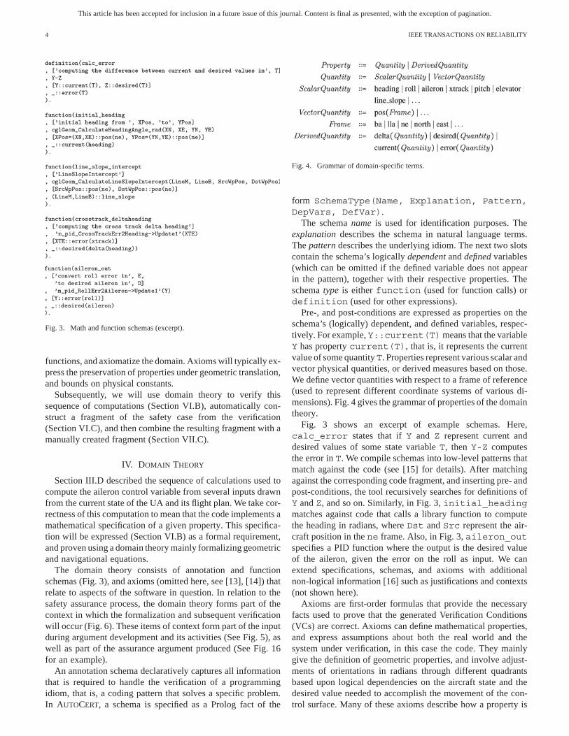
Fig. 3. Math and function schemas (excerpt).
functions, and axiomatize the domain. Axioms will typically ex-press the preservation of properties under geometric translation,and bounds on physical constants.
Subsequently, we will use domain theory to verify thissequence of computations (Section VI.B), automatically con-struct a fragment of the safety case from the verification(Section VI.C), and then combine the resulting fragment with amanually created fragment (Section VII.C).
IV. DOMAIN THEORY
Section III.D described the sequence of calculations used tocompute the aileron control variable from several inputs drawnfrom the current state of the UA and its flight plan. We take cor-rectness of this computation to mean that the code implements amathematical specification of a given property. This specifica-tion will be expressed (Section VI.B) as a formal requirement,and proven using a domain theory mainly formalizing geometricand navigational equations.
The domain theory consists of annotation and functionschemas (Fig. 3), and axioms (omitted here, see [13], [14]) thatrelate to aspects of the software in question. In relation to thesafety assurance process, the domain theory forms part of thecontext in which the formalization and subsequent verificationwill occur (Fig. 6). These items of context form part of the inputduring argument development and its activities (See Fig. 5), aswell as part of the assurance argument produced (See Fig. 16for an example).
An annotation schema declaratively captures all informationthat is required to handle the verification of a programmingidiom, that is, a coding pattern that solves a specific problem.In AUTOCERT, a schema is specified as a Prolog fact of the
Fig. 4. Grammar of domain-specific terms.
form SchemaType(Name, Explanation, Pattern,DepVars, DefVar).
The schema name is used for identification purposes. Theexplanation describes the schema in natural language terms.The pattern describes the underlying idiom. The next two slotscontain the schema’s logically dependent and defined variables(which can be omitted if the defined variable does not appearin the pattern), together with their respective properties. Theschema type is either function (used for function calls) ordefinition (used for other expressions).
Pre-, and post-conditions are expressed as properties on theschema’s (logically) dependent, and defined variables, respec-tively. For example, Y::current(T)means that the variableY has property current(T), that is, it represents the currentvalue of some quantityT. Properties represent various scalar andvector physical quantities, or derived measures based on those.We define vector quantities with respect to a frame of reference(used to represent different coordinate systems of various di-mensions). Fig. 4 gives the grammar of properties of the domaintheory.
Fig. 3 shows an excerpt of example schemas. Here,calc_error states that if Y and Z represent current anddesired values of some state variable T, then Y-Z computesthe error in T. We compile schemas into low-level patterns thatmatch against the code (see [15] for details). After matchingagainst the corresponding code fragment, and inserting pre- andpost-conditions, the tool recursively searches for definitions ofY and Z, and so on. Similarly, in Fig. 3, initial_headingmatches against code that calls a library function to computethe heading in radians, where Dst and Src represent the air-craft position in the ne frame. Also, in Fig. 3, aileron_outspecifies a PID function where the output is the desired valueof the aileron, given the error on the roll as input. We canextend specifications, schemas, and axioms with additionalnon-logical information [16] such as justifications and contexts(not shown here).
Axioms are first-order formulas that provide the necessaryfacts used to prove that the generated Verification Conditions(VCs) are correct. Axioms can define mathematical properties,and express assumptions about both the real world and thesystem under verification, in this case the code. They mainlygive the definition of geometric properties, and involve adjust-ments of orientations in radians through different quadrantsbased upon logical dependencies on the aircraft state and thedesired value needed to accomplish the movement of the con-trol surface. Many of these axioms describe how a property is

This article has been accepted for inclusion in a future issue of this journal. Content is final as presented, with the exception of pagination.
DENNEY AND PAI: AUTOMATING THE ASSEMBLY OF AVIATION SAFETY CASES 5
Fig. 5. Safety assurance methodology showing the data flow between the pro-cesses for safety analysis, safety argumentation, system development, and soft-ware verification.
preserved under addition or subtraction of . Others describethe validity of reversing the sign of a value while maintaininga property.
Like the schemas, axioms and verification conditions also useproperties that denote geometric and navigational concepts, in-cluding physical quantities such as heading and roll, con-trol surface settings like aileron and elevator, and framesof reference such as lla (lat-long-alt) and ne (North-East).
Much of this domain theory will be reflected in the resultingcomplete safety case. For instance, the schemas give rise tothe goals (and subgoals) of the safety case. The schemas arealso used to generate verification conditions. The external func-tions in the code base are represented in AUTOCERT as functionschemas. These are represented as nodes in the safety case. Fi-nally, the verification conditions are proved by a subset of theaxioms, and the proof is also represented as an evidence nodein the safety case.
V. SAFETY ASSURANCE METHODOLOGY
Fig. 5 shows our overall safety assurance methodology as adata flow among the different processes and activities applicableduring the development of the Swift UAS. Note that the figuremainly shows some of the key steps and data relevant for thispaper. Additionally, neither the iterative and phased nature ofthe involved activities nor the feedback between the differentprocesses have been shown.
We emphasize that safety analysis and argumentation (Fig. 5)are not post-development activities. Rather, they are performedin conjunction with system development and verification, sothat safety considerations are addressed from the outset. In par-ticular, safety analysis activities start from concept definition,and continue through requirements development, design, imple-mentation, verification, and operation. The data from the laterstages of development and operation serve to refine and vali-date earlier analyses.
In general, safety analysis drives safety case development.Safety analysis results are, therefore, at the core of the set ofheterogeneous information available to create the system safetycase. Thus, after performing early-stage safety analysis, weuse the results, which include the identified high-level hazards,the broad mitigation mechanisms, and safety requirements, tocreate a (skeleton of a) high-level, preliminary safety case, byfollowing the activities for argument development (Fig. 5).As development progresses, we repeat the safety analysis toidentify lower-level hazards, and the design decisions requiredto mitigate those hazards. In turn, we use these data to refinethe preliminary safety case into an interim safety case. Duringthese steps of safety case refinement, additional constraints onthe evidence required for substantiation become more clear,e.g., from the safety standards used, the development activities,and from the safety analysis of the system and its constituentelements. Additionally, during safety case refinement, we ob-tain some evidence from design and implementation activities.Substantiating evidence can be gathered from verification;and as additional evidence is obtained from operation, theassumptions made during the development can be validated (orinvalidated), so as to update both the safety analysis, and thecorresponding operational safety case.
A. System Safety Analysis
The system safety process that is being used in the ongoingdevelopment of the Swift UAS, is based on the framework of asafety risk management plan, such as [17] or [18]. The processincludes safety considerations into system design at an earlystage through hazard identification, risk analysis, and risk man-agement (labeled as safety analysis in Fig. 5). Hazard identi-fication and risk analysis are fundamental activities in safetyengineering involving, in brief, (a) identifying those situationsor conditions relevant to the system which, if left uncontrolled,have the potential to result in an undesirable loss event; and(b) characterizing the consequences, severity, and likelihood ofsuch situations and conditions. Broadly, in risk managementwe use the results of risk analysis to prioritize and mitigaterisks. We derive the system safety requirements during the earlystages of concept development and requirements formulation.The lower-level safety requirements, including those related tosoftware safety, are identified later when the system require-ments are better understood, and lower-level details are beingdesigned.
As input to the steps of safety analysis, we use a variety ofdata that give insight into potential hazards. During the earlystages of system development, these data include, but are notlimited to, the concept of operations, available design documen-tation for legacy systems (if applicable), and previously identi-fied hazards (often captured in a preliminary hazard list). In gen-eral, additional heterogeneous sources include the following.
1) Procedural, development, and safety standards imposingdesign and safety constraints on the system.
2) Procedures (distinct from procedural standards) describingoperations, e.g., for maintenance on range, before, during,and after flights, including maintenance, and the rolesplayed by the flight team members.

This article has been accepted for inclusion in a future issue of this journal. Content is final as presented, with the exception of pagination.
6 IEEE TRANSACTIONS ON RELIABILITY
3) Mathematical theory, e.g., the theory of aerodynamic sta-bility and control are used to derive parameters, included inthe control laws, that govern the safe operation of aircraft.
4) Assumptions, i.e., simplifying assumptions such as de-coupled dynamics: linear independence of latitudinal andlongitudinal models, are sometimes made in autopilotdesign, which break down when large angles of attackare considered; such assumptions have significant safetyimplications.
5) Vehicle flight logs, e.g., which show the absence ofmishaps for qualification testing, and also the systembehavior under specific flight conditions.
6) Calibration experiments such as those used to calibratesensors; the results of such experiments eventually appearin the control system software.
7) Hardware tests, e.g., static load tests used for determiningactuator sizes, tolerances, endurance, etc.
8) Aircraft models, e.g., geometric, and three-dimensionalCAD models, computational fluid dynamics models,among others, are used for deriving control parameters,and for visualizing safety aspects of the avionics.
9) Data-sheets providing component parameters and specifi-cations used in the aircraft.
10) Simulations which progressively evaluate the hardware,software and eventually the actual system to be flown.
11) Software models of the sensors, actuators, commands, andflight management.
12) Range safety calculations providing estimates on the ex-pected casualty rate based on the area in which the aircraftis operated.
13) Expert opinion, often including decisions which might notbe explicitly documented.
We believe that the main value of characterizing such hetero-geneous data is to manage the wider context of safety, e.g., toidentify and manage hazards arising from system interactions.In particular, although goals-based argumentation is largelyproduct focused, safety implications also arise from otherrelated sources, e.g., process and procedural deviations duringoperation, incorrect or implicit assumptions, etc.
Once hazards have been identified, we define mitigation mea-sures to reduce risk to acceptable levels. One specific outcomeof the risk reduction and mitigation step is requirements onsystem safety. These requirements take several forms, includingconstraints on the design, guidelines, and procedures for main-tenance, operation, etc. See Section VI.A for an example.
B. Safety Argumentation
The general idea underlying safety argumentation is to createa structured safety case to systematically justify safety claims,for instance by justifying that all identified hazards have beeneliminated or mitigated, such that mishap risk has been reducedto an acceptable level. As shown in Fig. 5, safety argumen-tation comprises the activities of argument development (themain focus of this paper) and uncertainty assessment [19] (outof scope for this paper).
The main activities in argument development are claimsdefinition, evidence definition and identification, evidence se-
lection, evidence linking, and argument assembly, of which thefirst four are adapted from the six-step method for safety caseconstruction [11], [20]. In particular, we consider the activity ofargument assembly, which is where our approach deviates fromexisting methodologies [10], [11] for safety argumentation,including the six-step method. This activity reflects the notionof assembling the data produced from the remaining activitiesto create a safety case (in our example, fragments of argumentstructures for the Swift UAS) containing safety claims andthe supporting evidence, linked through an explicit chain ofreasoning. More specifically, it reflects the notion of assem-bling lower-level auto-generated argument fragments withhigher-level manually constructed argument fragments. Thiscombination of bottom-up and top-down argument constructionis a novelty of our approach that further distinguishes it fromother existing approaches.
The activity of argument assembly accounts for (i) the inclu-sion of argument design criteria such as maintainability, compli-ance with safety principles, reducing the cost of re-certification,modularity,compositionofarguments,etc.;and(ii)automation.
Argument design criteria represent trade-offs made in the ar-gument architecture, which affect the overall structure and or-ganization of the elements of the argument. We envisage au-tomation in argument assembly to include the assembly andgeneration of
1) argument fragments from fundamental elements of an ar-gument, such as claims, evidence, and reasoning;
2) argument modules created using manual, automatic, andsemi-automatic means [13]; and
3) heterogenous data in the overall safety argument.Specifically in this paper, argument assembly involves, in part,the automatic creation of an argument structure from formalsoftware verification (implemented as model transformations),and its automatic inclusion into a manually created higher-levelargument structure. We describe the specifics of the relevanttransformations in Section VI.C.
Safety argumentation, which is phased with system devel-opment, is applied starting at the level of the system in thesame way as the system safety process, and then repeated atthe software level. Consequently, the safety case produced itselfevolves with system development. Thus, similar to [21], we candefine a preliminary, interim, and operational safety case to re-flect the inclusion of specific artifacts at different points in thesystem lifecycle. Alternatively, we can also define finer grainedversions, e.g., at the different milestones defined in the plan forsystem certification.
The argument structure of the Swift UAS, which we presentsubsequently in this paper, embodies a fragment of an interimsafety case.
C. Software Verification
As mentionedearlier,weuse our software verificationmethod-ology (Fig. 6) to create the lower levels of the software safetyargument. Fig. 6 shows some of the data (boxes) and verificationactivities (annotated arrows) involved, as well as the connectionsto the wider system safety process (dotted arrows).

This article has been accepted for inclusion in a future issue of this journal. Content is final as presented, with the exception of pagination.
DENNEY AND PAI: AUTOMATING THE ASSEMBLY OF AVIATION SAFETY CASES 7
TABLE IEXCERPT FROM SWIFT UAS HAZARD ANALYSIS
Fig. 6. Software verification methodology [13].
To verify the flight software in the Swift UAS, we formallyverify the implementation against a mathematical specification,and test low-level library functions against their specifications.In this paper we concentrate on formal verification usingAUTOCERT [22], whereas testing and verification using othertools is deferred to future work.
The specification formalizes software requirements which, inturn, we derive from system requirements during the safety anal-ysis. A logical domain theory (i.e., a set of axioms and func-tion specifications; also see Section IV) provides the contextfor formal verification. Axioms can be subjected to increasinglevels of scrutiny, going from simply assuming their validity, toinspections, up to testing them against a computational modelwhich, itself, is inspected [23].
VI. METHODOLOGY APPLICATION
A. Hazard Analysis
During hazard identification, Preliminary Hazard Analysis(PHA), and Functional Hazard Analysis (FHA) for the SwiftUAS, we systematically identified and documented the knownhazards, and brainstormed for new hazards, in close coopera-tion with the Swift UAS engineering team. We used documents
related to the concept of operations, preliminary design, oper-ating procedures, as well as other heterogeneous information(as identified in Section V.A). We also applied Failure Modesand Effects Analysis (FMEA) as part of bottom-up reasoningfor hazard identification.
The hazard categories identified include environmental haz-ards (e.g., unexpected air traffic in the range), energy releasehazards (e.g., thermal runaway of the onboard lithium polymerbattery), failure hazards (e.g., subsystem failures from unreli-able, unavailable or incorrectly constructed components), devi-ations from procedures (e.g., incorrect application of pre-flightchecklists), operational hazards (e.g., unanticipated pitch downduring landing), as well as interactions (e.g., miscommunicationbetween operator and air traffic control).
Table I shows an excerpt of the hazard analysis, for the de-scent phase of the UA induced by the LAND command (Fig. 1).We show (a small subset of) some of the relevant failure haz-ards in the avionics software (specifically, the autopilot), as wellas a hazard related to the flight control surfaces, which pose asafety risk during descent. Each of the failure hazards identi-fied here may be considered as the aggregation of the variousfailure modes of the corresponding component, although we donot show the FMEA in this paper. Several of the columns in theactual analysis, such as the effects on the immediate sub-systemsand the wider system, potential causes, mitigation measures andcorrective actions, etc., have been hidden here, to make the tablereadable. The hazard risk levels are determined qualitatively as acombination of the hazard severity and likelihoods, by applyinga risk classification matrix, e.g., as in [18]. The table also showsthe consequent definition of (some of) the relevant safety re-quirements which, when correctly implemented, are expectedto mitigate the hazards and reduce risk.
Some of the requirements shown are applicable at the systemlevel, while others are relevant for the software. There are alsorelations between (some) system-level safety requirements

This article has been accepted for inclusion in a future issue of this journal. Content is final as presented, with the exception of pagination.
8 IEEE TRANSACTIONS ON RELIABILITY
Fig. 7. Breakdown of autopilot functionality, giving low-level functional re-quirements related to software safety requirements.
and software (safety) requirements, due to the contributionof software to the system hazard. For instance, in Table I,the software safety requirement for the autopilot to producethe correct values of the control surfaces during descent(SAFR_AVCS_001) can be derived from the system safetyrequirement for the control surfaces to be within their specifiedranges during descent (SAFR_FLTCS_001). In fact, the formeris also a functional requirement of the autopilot (SR-3(d) inFig. 7, which lists an informal, high-level hierarchy of func-tional requirements for the autopilot module).
The autopilot functional requirements must be satisfied forthe correct and safe operation of the autopilot. This decompo-sition, based on the structure of the code defining the autopilotmodule and its subsystems, was created by a software engineerfamiliar with the autopilot software. We used this decomposi-tion as a guide when creating the autopilot software safety argu-ment (described subsequently in this paper, in Section VII.C.3).
Roughly speaking, the correctness of the autopilot module islogically dependent on showing the correctness of the under-lying subsystems, i.e., the FMS and AP, which the autopilot de-pends upon and initializes. The FMS interprets the list of com-mands that are supplied, and the transition between these com-mands must be correctly executed. The AP must then correctlycompute the output for each aircraft control surface (based uponthe new modes set by the FMS in the previous step). The cor-rectness of the autopilot requires that each subsystem properlycommunicate any state transitions, and then operate appropri-ately on that resulting state.
B. Formal Verification
In the previous section, we derived several low-level require-ments. Following our running example, we now concentrateon the aileron and elevator control variable calculations, andformalize and verify them against the software. Fig. 8 shows
Fig. 8. Specification (excerpt): formal assumptions and requirements [13].
a specification fragment consisting of assumptions about thecurrent aircraft state and flight plan, and requirements on sig-nals to the control surfaces. Note that the formal specification(Fig. 8) only concerns a small part of the behavior covered bythe larger informal specification (Fig. 7). More specifically, therequirements SR-3(d)-i and SR-3(d)-ii, in Fig. 7, are the re-quirements formalized in Fig. 8, while the informal assumptionsare implicit. Both the informal assumptions and requirements,and their formalized equivalents will eventually appear as as-sumptions, and claims, respectively, in the assurance argument(Fig. 15, and Fig. 16).currACPos is the current aircraft position in the North-East
frame of reference, whereas srcWpPos, and dstWpPos arethe current, and next waypoints, respectively, in the flight plan.The purpose behind the axioms, schemas, and domain theory ingeneral is to ultimately prove properties of the code via verifi-cation conditions. Given these assumptions on the aircraft state,we must show that the code that implements the descent phaseof the LAND command (Fig. 1) correctly modifies the aileronand elevator. To do so, we verify the code against its specifica-tion using AUTOCERT, which infers logical annotations on thecode under verification, using the annotation schemas (Fig. 3).
AUTOCERT then applies a verification condition generator,which uses the annotations and function specifications to gen-erate a set of VCs, logical conjectures which are sent to a suiteof Automated Theorem Provers (ATPs) along with the axioms.Most VCs conjecture that the regulation of a variable withinsome bounds maintains a given property. In Fig. 8, for the re-quirement ,51 verification conditions were generated. Of these 51, mostconjectured that the regulation of a variable maintained a givenproperty. The regulation involved the quadrant adjustments ofradian values or the reversing of the sign based on the cur-rent aircraft state. All 51 were proved using a suite of 5 ATPs.For the second requirement
, 13 VCs were generated. In the same wayas for the first requirement, the VCs correspond to the main-tenance of a given property under regulation through quadrantadjustments or sign reversals. All 13 of the verification condi-tions were verified using the same suite of 5 provers.

This article has been accepted for inclusion in a future issue of this journal. Content is final as presented, with the exception of pagination.
DENNEY AND PAI: AUTOMATING THE ASSEMBLY OF AVIATION SAFETY CASES 9
In effect, AUTOCERT checks the implementation against aformal specification in several steps, ensuring the followingpoints. (a) Individual code fragments correctly implementmathematical equations because, in general, there can be alarge semantic gap between mathematics and implementation.Concepts can be fused together or separated throughout thecode. (b) The sequence of implemented equations links togethercorrectly to meet a higher-level requirement. (c) Sufficient as-sumptions are given, and are necessary (i.e., are actually used).
Specifications consist of low-level assumptions and require-ments. An example of a low-level (informal) requirement mightbe that the code shall compute the rotation matrix. The corre-sponding formal requirement would state that the code must im-plement a particular mathematical concept. The formal verifica-tion of this requirement then traces that mathematical conceptto a sequence of lines of code, and reveals its logical depen-dency on other requirements and assumptions. Such low-levelrequirements often need to be verified during reviews, and canrequire the tracing and decomposition details provided by theformal analysis.
Each branch of the formal verification and correspondingauto-generated argument shows the logical slice of the systemdataflow that is relevant to meeting that requirement. Theformal argument has two kinds of verification steps: that amathematical concept is implemented, and logically dependson other mathematical concepts or assumptions; and a side con-dition, i.e., a verification condition (VC), holds. The former areinteresting, but the latter less so, and could for most purposesbe safely hidden.
In fact, there are two levels of proof. AUTOCERT is an infer-ence tool that matches implementation in the code to mathe-matical concepts, thus allowing formal requirements to be de-composed, and to be traced to code. It is the upper-level proof(the tracing relations comprising decompositions and logical de-pendencies that establish that lower-level requirements entailhigher-level requirements) that is represented graphically in theargument structure. However, the (lower-level) proofs of VCsusing automated theorem provers (external to AUTOCERT) areconsidered evidence.
C. TransformationIn principle, there are two ways in which a formal method can
be integrated with the construction of a safety case: (i) the outputof AUTOCERT can be transformed into a safety case fragment, or(ii) safety case fragments can be transformed into formal spec-ifications that are then input to AUTOCERT. We consider thesetwo cases, in turn.
1) From Formal Proofs to Argument Structures: Recall thatFig. 2 illustrated the sequence of calculations used to computethe aileron control variable from several inputs drawn from thecurrent aircraft state and the flight plan. AUTOCERT generates adocument (in XML) with information describing the formal ver-ification of requirements. The core of this document is the chainof information relating requirements back to assumptions. Eachstep in the document is described by (i) an annotation schemafor the definition of a program variable, (ii) the associated VCsthat must be shown for the correctness of that definition, and (iii)the variables on which that variable, in turn, logically depends.
The goals (and subgoals) of the argument structure have beenderived from the applied annotation schemas. The subgoals cor-respond to the schema’s logically dependent variables, and theVCs related to each goal. An argument for a VC is a proof, gen-erated using a subset of the axioms, which forms the evidenceconnected to the VC goal. We include the prover used as context.We also create goals out of function specifications from externallibraries used in the software and its verification. Arguments forthese goals can be made with evidence such as testing or inspec-tion. Each subgoal derived from an annotation schema is a stepin the verification process.
The transformation also creates assumption nodes that re-late to code variables (e.g., x represents altitude), which are at-tached to goals. In principle, assumptions can be placed any-where in scope of the goal corresponding to the formal require-ment. One choice is to attach all the formal assumptions directlyto the goal requirements, which can be done by repeating the as-sumptions at each goal which uses them or by using cross-ref-erences for repeated nodes. Another choice is to attach assump-tions to the most recent common ancestor of all formalized re-quirements. Our algorithm attaches them at the correspondinggoal requirements.
During the process of merging the manually created argu-ment structure with the auto-generated ones, we replace distinctnodes of the former with the tree fragments generated fromAUTOCERT. Specifically, we graft the top-level goals of thelatter onto the appropriate lowest-level nodes of the former. Weannotate these nodes with unique comments, autocert:id,to relate them to a tree in the automatically created file, meaningthat the goal with tag autocert:id is to be solved withAUTOCERT.
2) From Argument Structures to Formal Specifications:Often, an argument structure fragment may be created beforethe software verification is completed. Here, we can annotatenodes with autocert:id, where id identifies formal state-ments that are to be extracted in a formal specification. Basedon the type of node in which the identifier occurs, the tool inferswhether the labeled node is a requirement or an assumption.After running AUTOCERT on the generated specification, wecan graft the resulting proofs back into the argument structure.
In the autopilot case, the nodes representing the aileron andelevator control verification would have text representing bothan informal description of the system requirement being veri-fied, and the corresponding formal requirement, resulting in thespecification in Fig. 8.
VII. SWIFT UAS SAFETY ARGUMENT
A. Goal Structuring NotationFig. 9 shows the main elements of the Goal Structuring No-
tation (GSN) [11], which we use to document the Swift UASsafety case.
An argument structure in GSN contains a top-level goalstating the safety claim, e.g., a given system is acceptablysafe. We develop goals into sub-goals using strategies, and thisprocedure is continued until there are elementary claims thatcan be connected to solutions, i.e., the available evidence. Thestructure also specifies the assumptions made, the justifications

This article has been accepted for inclusion in a future issue of this journal. Content is final as presented, with the exception of pagination.
10 IEEE TRANSACTIONS ON RELIABILITY
Fig. 9. Goal structuring notation (GSN) for safety case argument structures.
Fig. 10. Argument architecture for the Swift UAS.
if any, e.g., for the strategies used or the sub-claims created,as well as the context in which the claims, strategies, and so-lutions are valid. We link goals, strategies, and solutions usingthe is-solved-by relation (shown with the filled arrowhead),while context, assumption, and justification elements requirean in-context-of relation (shown with the hollow arrowhead).Note that GSN nodes can also contain pointers to more detailedinformation, and the description of a GSN node summarizesthese details.2 For example, detailed definitions can be givenexternally, and linked to by a context node whose descriptioncould simply be an identifier.
GSN provides a graphical annotation for goals and strate-gies to indicate that they are to be developed, i.e., they are in-complete. GSN additionally contains notations for modularity,e.g., to reference elements in different modules using so-calledaway nodes. For instance, in Fig. 9, AG1 is an away goal, with
denoting the reference to the relevantmodule.
B. Argument Architecture
The argument architecture (Fig. 10) for the Swift UAS safetycase describes the organization of the underlying argument tosatisfy various attributes such as compliance, comprehensi-bility, validity, maintainability, etc. Our main concern was toassure that all hazards, and system contributions to hazards,
2Also note that that the node coloring shown is aesthetic and specific to ourtoolset. Presently, it does not provide semantics like the links do.
Fig. 11. Module diagram of the Swift UAS safety case, reflecting a part of theargument architecture.
identified in the safety analysis (Section V.A), have beenacceptably managed.
We adopt a hazard-directed style of argumentation, where wedevelop the system safety claim by addressing hazards arisingfrom the system organization, its interactions, and its operations.We develop the resulting claims first over the operating phases,subsequently over the hierarchical system architecture and itsinteractions, and eventually over lower-level components. Theintent is to trace hazard mitigation through the safety argument,in part, to the behavior of system components. For instance, toassure software safety, the safety case includes explicit correct-ness arguments to demonstrate that software contributions to theidentified system hazards are acceptable.
In this paper, we mainly present an end-to-end slice of theoverall safety case (highlighted in boldface in Fig. 10, andshown in Fig. 11 as a modular organization), which corre-sponds to the system operation during descent (Section III.C),including the low-level computations performed in the autopilot(Section III.D). It traces the system safety claim to the identifiedhazards, the corresponding safety requirements (Section VI.A),and to the evidence from formal verification (Section VI.B).
The system safety claim, that the Swift UAS is acceptablysafe in the context of a specific mission, in a specific configura-tion, on the defined range where it is to be operated, under spe-cific weather conditions, is made in a system-level argument. Asshown, we link this claim first to an aircraft-level argument inthe descent phase of operation, then through the aircraft systemarchitecture to the avionics software, and eventually to a failurehazard of the autopilot module. We demonstrate the mitigationof this hazard through a correctness argument in which the sup-porting evidence comprise proofs of correctness, that the PIDcontrollers for the aileron and elevator control surfaces producethe required values.

This article has been accepted for inclusion in a future issue of this journal. Content is final as presented, with the exception of pagination.
DENNEY AND PAI: AUTOMATING THE ASSEMBLY OF AVIATION SAFETY CASES 11
Fig. 12. System-level argument fragment for the Swift UAS.
C. Manually Created Safety ArgumentThe manually created argument fragment mainly concerns
the airborne system, i.e., the UA. We construct this argumentbased on the hazard analysis (Section VI.A), and it is layeredaccording to the argument architecture (Fig. 10).
In Fig. 11, the manually created argument fragment corre-sponds to the arguments contained in modules M1 throughM17, whereas modules M18 and M19 contain the auto-gener-ated fragments (described in Section VII.D). In this paper, wemainly present the system-level argument (module M1), andthe argument for the software (modules M13, M16 and M17);more details on the overall argument are in [14].
1) Module M1. System-Level Argument: The system safetyclaim, i.e., that the Swift UAS is acceptably safe, is made inthe context of a specified mission, a particular configuration,the location and site of operation, and the weather conditionsduring operation (Fig. 12). Acceptable safety is as defined inNASA procedural requirements for range safety, NPR 8715.5A[24], to which we also refer in the context of the safety claim.We develop this claim by argument over identified hazards, andsubsequently over the physical architecture of the system and itsinteractions (since the argument shown is a slice, the argumentover operational hazards is hidden in this view).
The result is claims about the system components, i.e., theGCS, the communication infrastructure, the airborne system(the UA), and the relevant interactions. As shown, we use anaway goal AG1 for the claim of mitigating hazards posed bythe UA, to indicate that it is developed in a different module,i.e., in the aircraft level argument (corresponding to moduleM2 in Fig. 11, and labeled as inFig. 12). Therein, we develop the claim of mitigating hazardsposed by the UA, first by argument over the operating phases,and then in general by argument over hierarchical breakdownover the system architecture, i.e., the fuselage systems andthe Common Payload Data System (CPDS), into a claim ofmitigating (avionics) software failures during descent. (See[14] for more details).
2) Module M13. Avionics Software Argument: The argumentstructure for justifying the claim of mitigating avionics softwarefailures during descent uses three strategies (Fig. 13): (i) S6, va-lidity of the input to software, (ii) S7, satisfaction of softwaresafety requirements, and (iii) S9, correctness over the (soft-ware) architectural breakdown. Note that these strategies rep-resent one set of strategies that we chose for assurance. Otherstrategies, such as argument over the set of identified failures orfailure modes, can also be used.

This article has been accepted for inclusion in a future issue of this journal. Content is final as presented, with the exception of pagination.
12 IEEE TRANSACTIONS ON RELIABILITY
Fig. 13. Argument fragment for the avionics software in the Swift UAS.
Fig. 13 shows how the claim of mitigating avionics softwarefailures during descent is traced to the identified high-level func-tional safety requirements, which appear as specific goals.
• G4: The autopilot executes safe maneuvers for all com-mands during descent.
• G5: The autopilot interprets all commands correctly duringDescent.
• G6: The autopilot maintains accurate state informationduring descent.
Additionally, the argument traces the mitigation of software fail-ures during descent to the reliability of the input sensors (shownas the away goal AG1, in Fig. 13).
Note that arguing correctness is not always required whenmaking and justifying a safety claim. However, for the SwiftUAS, the correctness of the avionics software is itself safetyrelated, i.e., incorrect behavior is unsafe behavior. Becausethe claims given here are informal, and although we referto correctness, this should be understood to be informal. Wemake this context explicit in the argument fragment, in part,through the definition of correctness of the software compo-nents (C6).
In the particular case of the autopilot, which is part of theavionics software, and also forms a part of the failsafe systemfor contingency management, its correct behavior (in referenceto its informal specification given in Fig. 7) is required to as-sure safety. We show this requirement as the away goal AG2in Fig. 13, referencing the module (cor-
responding to the module M16, in Fig. 11) that contains the au-topilot software argument, which we describe next.
3) Module M16. Autopilot Software Argument: The mainclaim in the argument for the autopilot software is that its be-havior during descent is correct (G14, in Fig. 14). We apply fourstrategies to develop this claim: (i) S1, validity of the specifica-tion; (ii) S2, correctness of the implementation; (iii) S3, satis-faction of higher-level requirements; and (iv) S13, validity ofthe mapping between state variables and aircraft data. We applythe strategies S1 and S2, over the constituent modules of the au-topilot, i.e., its software hierarchy.
Fig. 14 also shows how the argument for the autopilotsoftware explicitly captures logical dependencies betweencorrect software behavior, and heterogeneous information.Specifically, to support the main claim in the argument, weneed to show, in part, that the functionality contained in itsmodules is also correctly specified. Thus, for the claim thatthe computation of angle of attack is correctly specified (G15),we use the data from wind tunnel calibration experiments ofthe pitot probe (air data sensor), and reviews of the softwarespecification conducted against the theoretical formula forangle of attack, as supporting evidence (nodes E3 and E4,respectively). Furthermore, to support the main claim (of theautopilot software argument), we also need to show, in part,that the autopilot controller (AP) implementation is correct(shown as the away goal AG1 in Fig. 14, referencing module
, which corresponds tomodule M17 in Fig. 11).

This article has been accepted for inclusion in a future issue of this journal. Content is final as presented, with the exception of pagination.
DENNEY AND PAI: AUTOMATING THE ASSEMBLY OF AVIATION SAFETY CASES 13
Fig. 14. Argument fragment for the Swift UAS autopilot module.
Here, it is worth noting that the argument structure mirrors,to an extent, the (informal) breakdown of autopilot functionality(Fig. 7). For example, the main requirement of autopilot correct-ness (Fig. 7) maps3 to several corresponding claims in the safetycase, one of which is the claim of autopilot correctness duringdescent (Goal G6, in Fig. 14). Subsequently, the claims aboutcorrect implementation (and valid specification) of the autopilotclass (goal nodes G3, G2), the FMS class (goal nodes G4, G1),and the AP class (goal nodes AG1, G5) in Fig. 14, respectively,map to the informal requirements SR-(1), SR-(2), and SR-(3) inFig. 7.
There are similar such claims for the correctness of the au-topilot for other flight phases, but these have not been shownin the paper mainly because we focus on a slice of the overallargument, and on the descent phase. Furthermore, not all therequirements in Fig. 7 have been transferred to the argumentstructures because, in part, our main focus for the paper was onthose requirements relevant for the slice we considered.
3Note that the wording of the requirements differs slightly from the wordingof the claims in the safety case, e.g., in the latter we differentiate between theimplementation and the specification, whereas in the former, as shown in Fig. 7,this distinction is not made.
4) Module M17. Autopilot Controller Argument: The maingoal in the autopilot controller (AP) argument (Fig. 15) is that itsimplementation is correct. To demonstrate that this claim holds,our strategy is to show the correct implementation of its codeblocks, one of which implements the PID controllers for theelevator and aileron control surfaces (shown in Fig. 15, as theaway goals AG1 and AG2 respectively).
Once again, it is worth highlighting the correspondence be-tween the claim in goal node G4, the low-level software safetyrequirement it represents (SAFR_AVCS_001 in Table I), andthe system safety requirement (SAFR_FLTCS_001 in Table I)from which the software safety requirement was, in turn, de-rived. Additionally, the claim in goal node G4 in Fig. 15 cor-responds to the informal requirement SR-3(d) in Fig. 7, whilethe sub-claims in the away goals AG1, and AG2, respectively,correspond to the sub-requirements SR-3(d)i.
Furthermore, because these requirements were formally spec-ified (Fig. 8), we can create formalized claims for AG1 and AG2(described next). After formalizing the claims, we auto-generatethe supporting argument fragments (reflecting modules M18 andM19 in Fig. 11), and then auto-assemble them into the argumentarchitecture.Now,wedescribe theauto-generatedargument.

This article has been accepted for inclusion in a future issue of this journal. Content is final as presented, with the exception of pagination.
14 IEEE TRANSACTIONS ON RELIABILITY
Fig. 15. Argument fragment for the autopilot controller containing claimsabout PID controllers for the UA control surfaces.
D. Automatically Generated Safety ArgumentFirst, we formalize the claims in the leaf nodes of Fig. 15, i.e.,
that the implementations of the PID controller for the aileronand the elevator control variables are correct. The formaliza-tion step is the point where we relate variables and constants tophysical artifacts, and justify this correspondence. Effectively,we relate our formal model to the world here.
Fig. 16 shows how this task has been accomplished. The main(informal) claim is that the implementation of the PID con-troller is correct for the aileron control variable (Goal G122 inFig. 16, corresponding to away goal AG2 in Fig. 15). We applythe strategy of formalization (S19) in the context of the relevantdomain theory, using the AUTOCERT specification language. Ofthe resultant sub-claims, one of them (Goal AC1) is the formal-ized statement of the informal claim, i.e., the formula producedby translating the informal requirement using the chosen formallanguage. Any formal argument relies on explicit assumptionsabout the artifact under verification, and in this case the assump-tions relate to aircraft state variables. Assumptions on goals aretypically about the system (e.g., the system operated correctly),whereas assumptions on strategies are typically about the assur-ance (e.g., the hazard is analysis complete). Here, the assump-tions relate to code variables, and so refer to the system (e.g.,represents altitude), and are therefore attached to goals.
In principle, assumptions can be placed anywhere in scope ofthe goal corresponding to the formal requirement. One choiceis to attach all the formal assumptions directly to the formal-ized claims. To do so, we could repeat the assumptions at each
goal which uses them or by use cross-references for repeatednodes. Another choice is to attach assumptions to the most re-cent common ancestor of all formalized requirements. Our al-gorithm attaches them at the corresponding goal requirements,e.g., formalized assumption FA1 attached to formalized claimAC1. Although all the relevant assumptions (see Fig. 8) are tobe attached, we have only shown one due to space constraints.
In addition to the reliance on explicit assumptions, a formalargument also relies on the validity of the formalization, that is,on the correspondence between the formal artifacts we reasonwith, and the physical artifacts they model, to engender confi-dence. In Fig. 16, we express this result as a supporting claim(G123) after applying the strategy of formalization (S19).
The argument structure used to justify the formalized claimshows the structure of the verification (only one step has beenshown in the formal verification). To auto-generate the argu-ment structure, we use the verification information produced bythe AUTOCERT tool [22]. In particular, AUTOCERT decomposesthe formal equivalent of the claim under consideration intoa number of sub-claims and side conditions, i.e., VCs, viarepeated property decomposition. Then, automated theoremprovers can discharge these formulas. AUTOCERT assumes thatlow-level library functions meet their specifications, and doesnot verify their bodies. Therefore, evidence of this assumptionhas to be provided through an alternative means, e.g., bytesting, or from an inspection.
The fragment outlines the sequence of intermediate compu-tations in the code used to establish the relevant goal, which istypically a property on a variable. Some of these intermediatesteps correspond to lower level goals.
As mentioned earlier, Fig. 16 only shows the initial stepsof the auto-generated argument to support the (formal equiv-alent of the) claim on the aileron control variable, outputm_aileron_m1p1, whose property is stated in the goal AC1.This property is the condition that must be shown to hold for theargument to hold. The strategy used asserts that the correctnessof the claim is shown by decomposition of the correctness prop-erty, where the notion of decomposition is that embodied withinAUTOCERT. The context (AC6) clarifies that the decompositionis of the correctness property at line 542, which is in referenceto the original source code.
Next, we see the VC that must be shown to achieve this mainclaim (AC18) is also a goal (albeit incomplete, as no proofshave been generated). The claim in AC28 represents a logi-cally dependent variable of a schema, m_rollError_rad,and its property; though there may be multiple logically de-pendent variables in general, here it is the case that the aileroncontrol variable, output m_aileron_m1p1, is directlylogically dependent only on the variable m_rollError_rad.This goal also represents the start of a recursive instance of theargument structure tree, which exhibits similar reasoning untilit reaches the system assumptions or axioms.
As mentioned earlier, ATPs discharge the VCs, wherein theproof provides the evidence, and the prover provides context.Thus, the solution node AC16 indicates that a proof was suc-cessfully found (using the theorem prover Vampire-0.6), and thecontent of this node shows the path to the proof object ratherthan the proof itself. The argument structure also needs to rep-

This article has been accepted for inclusion in a future issue of this journal. Content is final as presented, with the exception of pagination.
DENNEY AND PAI: AUTOMATING THE ASSEMBLY OF AVIATION SAFETY CASES 15
Fig. 16. A step in the auto-generated argument structure fragment for the aileron PID controller, after formalization of an informal claim.
resent any assumptions that have been made about library func-tions, and the methods, if any, that have been used for verifica-tion; this information is obtained from a separately specified file.Finally, the provers use various domain theories to dischargeVCs; the full text of the list of domain theories includes suchtheories as arithmetic reasoning and transformation geometry.
Note that the properties being decomposed here can be tracedto specific lines of code given in the context nodes, e.g., AC6,AC34, and so on. Additional context nodes (C71, AC4, AC32,etc.) also indicate the schemas that have been applied, i.e., theformulas that have been used. When the safety case is beingevaluated, those formulas will need to be inspected by a domainexpert for validity.
The argument could be restructured so that there is a singlecontext node referencing the entire domain theory, which anexpert would then need to inspect, rather than checking eachindividual formula at each decomposition step. However, itis important to know for traceability where the mathematicalconcepts, i.e., low-level requirements, have been implementedin the code. By making the decomposition structure explicit, asin Fig. 16, the automated fragment provides this traceability,although the entire fragment can be thought of (and for-mallyrepresented) as a single hierarchical item of evidence[25]. Although we could replace the argument underneath goalnode AC1 with a logically equivalent decomposition, low-leveltraceability information is lost when the decomposition struc-

This article has been accepted for inclusion in a future issue of this journal. Content is final as presented, with the exception of pagination.
16 IEEE TRANSACTIONS ON RELIABILITY
Fig. 17. Fragment of a draft safety case narrative relating to the correct imple-mentation of the aileron PID loop [14].
ture is not made explicit. The steps are similar for the elevatorcontrol variable.
Fig. 17 shows a fragment of an automatically created safetycase narrative, corresponding to a step in the auto-generatedfragment.4 We also automatically create such an argument frag-ment (or its narrative) for the elevator control surface (referto [14] for details). The narrative report is generated from thesame verification information used to generate the (formallyconstructed part of) the argument. It can be seen as a textualrendering of the formal argument, which highlights certain keytracing information, including traces from (i) high level require-ments to low level requirements, (ii) requirements to assump-tions, (iii) requirements to code, (iv) requirements to concepts(mathematical concepts used to meet requirements), and (v) re-quirements to evidence (such as proofs). These reports are in-tended to serve as aids during code reviews.
E. Automatically Assembled Safety Case
Once the automatically generated safety case fragment hasbeen created, it must be merged with the manually created frag-ment (described earlier in Section VII.C). To do this (as men-tioned earlier in Section VI.C), we use unique identifiers, and as-sociate the top-level goals in the auto-generated argument withthe relevant incomplete goals from the manually created frag-ment, i.e., for each top level requirement from the AUTOCERT
4Creation of the narrative, in fact, is logically independent of whether theargument fragment is manually created or auto-generated; for more details, see[26], and [27]. Note also that the report lists several assumptions that were notused in the corresponding formal specifications.
Fig. 18. Bird’s eye view of an end-to-end slice of the overall system safety casefor the Swift UAS.
verification, we match nodes in the auto-generated fragmentwith nodes in the manually created fragment via the identifier.Then, to complete the argument started in the manually createdsafety case, we graft the two auto-generated argument trees ontothe appropriate, manually created nodes.
Fig. 18 shows a bird’s eye view of the resulting end-to-endslice (an open box equivalent of the module diagram in Fig. 11),comprising the manually created fragment, and the automati-cally generated fragment, both of which were created, and thenautomatically assembled using our toolset AdvoCATE [27].
VIII. DISCUSSION
It is important to note that, because the Swift UAS is underdevelopment, its safety case (and the argument fragment that wehave presented) is interim in the safety case lifecycle. To fullyjustify the top-level claim of system safety, we also require (re-peated) evidence of safe flight and other evidence from opera-tion (which is contingent on mission specific configurations andweather conditions). This evidence forms part of the operationalsafety case, which we have yet to create. We make the followingobservations about the use of our methodology and the develop-ment of safety arguments in general, following which we outlinesome avenues for further enhancing our work.
A. Observations
1) Heterogeneity: Safety cases are necessarily heteroge-neous in nature. Even in arguments that address softwareconcerns alone, heterogeneous evidence needs to be consid-ered. For example, in Fig. 14, one leg of the argument fragment

This article has been accepted for inclusion in a future issue of this journal. Content is final as presented, with the exception of pagination.
DENNEY AND PAI: AUTOMATING THE ASSEMBLY OF AVIATION SAFETY CASES 17
assures correct computation of the aircraft angle-of-attack. Theevidence includes, among other things, wind-tunnel testing ofthe air-data (pitot) probe, because a calibration constant rele-vant to the pitot probe appears as a parameter in the code. Whilesoftware verification evidence for this function, as requiredby traditional certification processes, would mainly need toshow that the code implements the specification, the assuranceargument goes further: it highlights that the claim (of correctcomputation of angle of attack) also relies on the evidence thatthe sensor is appropriately calibrated.
2) Improving Comprehension: One of the primary motiva-tions for creating a safety case is to communicate safety infor-mation to the relevant stakeholders. Hence, we believe that asafety case should not be viewed as a static, unchanging arti-fact. Rather, as a formal record of that which has been done (andcontinues to be done) to make a system safe, it is the means forcontinually monitoring and assuring safety throughout the life-cycle of a system. We also believe that a graphical argumentstructure is intuitively superior at communicating to a regulator,the claims, assumptions, justifications, and evidence that havebeen assimilated for assuring that a system is acceptably safe.The argument structure is an index into this compendium of in-formation, providing both a global overview, and a way to navi-gate to supporting information and examine the details (with ap-propriate tool support). The argument structure can also be rep-resented textually (cf. Fig. 17); however, we want a structuredformalism which shows the decomposition down to low-levelrequirements, and eventually to evidence.
With the specific case of encoding the reasoning underlying adeductive verification as a GSN argument structure, as given inthispaper, thereareacoupleofadvantages ingraphicallyshowingthe existing level of detail: (a) a unified notation, i.e., the GSN, isavailable to reviewbothhigh-level systemclaimsandlower-levelsoftware claims, assumptions, context and evidence; and (b) theautogenerated argument structure (e.g., Figs. 16 and 18) high-lights the exact reasoning used and the traceability from require-ments to code, giving a basis to gauge whether the output from theverification tool is trustworthy. Demonstrating traceability fromhigh-level requirements to low-level requirements, and eventu-ally to source code, is typically mandated by aviation safety as-surance standards. Thus, this traceability information, which wecapture in the auto-generated argument, is useful to identify thosemathematical concepts that have been used, and where those con-cepts have been captured in the code.
Effectively, a graphical argument structure can explicitlyhighlight the logical and stochastic interdependence betweensystem elements and software in the safety assurance case, soas to better explain the contribution of software to system safetyconcerns. Nevertheless, there is a need to hide some details andto manage the size of the argument. For instance, a regulatormay not wish to see the very low-level details of some formalverification, such as the proof of a VC. In this case, there are atleast two ways to modularize or abstract argument structures: (i)using GSN modules (Fig. 11), and (ii) automated hierarchicalabstraction [25], which can substantially reduce the numberof nodes that are shown in a graphical view. Hierarchy andmodularization are orthogonal concerns to the work presentedin this paper, and out of scope.
Automation can also assist in creating instance argumentsfrom their corresponding abstract argument patterns [28].Effectively, a safety analyst then deals with the abstract safetyargument, which is smaller and more manageable. In fact, thestyle of decomposition used during the verification of low-levelrequirements (see Fig. 16) can be formally defined as theAUTOCERT property decomposition pattern [29]. We have alsoimplemented an architecture decomposition pattern, which isto be used when the decomposition style is over sub-systems,wherein the successive steps of the decomposition emphasizeassume-guarantee contracts between sub-systems. This de-composition could also, in principle, be replaced with a logicalequivalent, but we believe the derived contracts are very usefulin providing insight into the assurance of the system.
How a safety argument is initially structured is likely to playan appreciable role in its comprehensibility and complexity. Forinstance, in the Swift UAS safety case, one of the main strate-gies in the aircraft-level argument (module M2 in Fig. 11) is toargue that hazards across all operating phases have been miti-gated. This argument is followed by the argument over the ar-chitectural breakdown of the airborne system (e.g., in moduleM5 in Fig. 11). This approach allows us to address, at the outset,those hazards whose risk is probabilistically dependent on themission phase, e.g., failure of the nose wheel actuator may notbe hazardous during the cruise phase, but it is a hazard duringlanding.
An alternative organization is to develop the relevant claim,first by argument over the architectural breakdown, and thenover the relevant operating phases. We believe that this ap-proach facilitates the creation of a safety argument which maybe both easier to maintain and better modularized. In general,such choices are tied to argument design criteria (Section V.B),and need careful consideration early during the development ofthe safety argument.
3) Reducing Errors, and Improving Confidence: There area variety of errors in safety case construction that could beeliminated by automation. For example, syntactic errors canbe eliminated by simple syntax checking, and acyclicity inarguments can be checked by ensuring that there are no loopsin the argument structure. The specific type of errors that arereduced here are logical fallacies in those parts of the argumentthat have been auto-generated from deductive verification.Logical fallacies in an argument can be avoided by verifyingthe argument, or by constructing it automatically from artifacts(which, of course, need their own appropriate verification). Inthis work, we present one approach to automatic constructionof argument fragments. The approach also requires explicitspecification of assumptions and formal requirements, and canreveal both missing assumptions, and unused assumptions.
There is a need for a quantitative assessment framework[30] to support decision making and argument assessment, e.g.,whether an argument is valid and covers sufficient information,whether the evidence supplied is trustworthy, and the amountof confidence that can be justifiably placed in the claims madealong with the supporting arguments. This work corresponds tothe activity of uncertainty assessment, in our methodology.
There are a variety of ways to deal with sources of doubt ina safety case. Our previous work [19] identifies one way for-

This article has been accepted for inclusion in a future issue of this journal. Content is final as presented, with the exception of pagination.
18 IEEE TRANSACTIONS ON RELIABILITY
ward using Bayesian probabilistic reasoning, for a quantitativeconsideration of uncertainty in argument structures. Confidencearguments provide another way to deal with some sources ofdoubt within the safety case, by creating an argument structurejustifying the reduction of assurance deficits. Other ways to im-prove confidence in an assurance case also exist, such as elimi-native induction, and the use of Dempster-Shafer theory.
Additionally, we have identified an initial set of metrics thatwe believe will support this need [14]. In brief, these includecoverage measures for hazards, higher-level and lower-levelsafety requirements, measures of (internal) completeness, alongwith simple measures of argument structure size. In large safetycases, such metrics can conveniently summarize the state of thesafety argument during system evolution. An implicit assump-tion underlying the coverage measures that we have definedis that the argument chains in the safety case are themselvesvalid. Manually created, inductive arguments can be systemat-ically reviewed for identifying argument fallacies, as in [31],which is part of our ongoing work to improve confidence inthe Swift UAS safety case. Assessing argument validity, and in-cluding this notion into the coverage measures, appears to be apromising mechanism also to support decision making.
B. Enhancements
Although we have only verified one small part of the system,we can potentially do much more. Although the AUTOCERT toolis aimed at one specific kind of analysis, we intend to com-bine the results of other kinds of formal verification. AUTOCERTprovides a proof that source code complies with a mathemat-ical specification. As part of its analysis, AUTOCERT reverse en-gineers the code, sifting through potentially overlapping frag-ments to create links from the code to high-level functional de-scriptions of concepts used in requirements. The functional de-scriptions are specified by annotation schemas, and AUTOCERTworks by inferring annotations at instances of these patterns. Itthen generates the chain of reasoning which allows the require-ments to be concluded from the assumptions, where each linkin that chain corresponds to a particular implementation pattern.It thus provides a decomposition of the argument which lendsitself naturally to inclusion in a safety case. However, not allmathematical properties are best specified in such a composi-tional dataflow style, and we plan to actively investigate inte-grating results from other tools.
As our work progresses and matures, we anticipate devel-oping recommendations for a safety case methodology that isaligned with NASA standards and procedures. Now, we listsome specific lines of work that we believe are worth pursuing.
1) Additional Formal Verification: The low-level claims thatwe verified were based on functional and physical unit cor-rectness. There are other properties that should be checked inthe avionics software, such as runtime safety and physics-basedbounds. One possible way to do this is to combine results andreasoning from different (verification) tools, as has been illus-trated for the AUTOCERT tool in this work.
2) Additional Automation and Assembly: Our hazard anal-ysis has been conducted manually. However, there is poten-tial for automation, especially when considering hazard iden-tification guided from definitions of the system boundaries, as
well as from its functional and physical decompositions, i.e.,we hypothesize that it is possible to automate some part of thehazard analysis, in particular via the systematic enumeration ofthe combinations of system components or their interactions atthe defined system boundaries. We believe that this will amelio-rate the integration of safety cases into existing processes.
3) Inclusion of Formal Verification Knowledge: There aremany different ways of converting formal verification knowl-edge into safety case fragments; the structure of the safety caseis driven by both the safety methodology, and the verificationmethodology.
Examples of high-level choices include whether to decom-pose over all requirements, versus all scenarios, or all codebranches. Rather than hard-coding these design choices inthe transformation, they could be represented declarativelyusing templates. This approach would give us control over thestructure of the generated safety case, and let us more easilyinvestigate and compare different structures.
There are also choices in how to layout the generated safetycase. We have chosen to duplicate shared VCs, but they couldbe shared as a directed acyclic graph.
4) Alignment With NASA Standards, Requirements, andGuidelines: NASA has numerous safety-relevant proceduralrequirements, standards, and guidelines at both the softwareand system levels. It will be important to develop a safetycase methodology which is aligned with these. We also planto continue our work on uncertainty assessment in argumentstructures [19], both with respect to its theoretical basis and itsapplication to our target system, so as to be compatible withNASA’s efforts in Probabilistic Risk Assessment (PRA) [32].
5) Safety Case Manipulation: The inclusion of automati-cally generated fragments, and all relevant sources of informa-tion, will lead to increasingly large safety cases. Existing mech-anisms for managing large argument structures are limited, andwe believe they should be amenable to manipulation in variousautomated ways. The Query-View-Transformation (QVT) stan-dard for model manipulation could be applied here.
We also believe that introducing hierarchy into safety cases,i.e., hicases [25], is a promising approach that could reducethe burden of review. There is also a natural fit with automat-ically generated cases, as hierarchical structuring can also begenerated automatically. Indeed, there are additional forms ofmeta-information that can also be generated to aid review.
IX. CONCLUSION
We have shown that it is feasible to automatically assembleauto-generated fragments of safety cases derived from aformal verification method, i.e., proofs of correctness usingAUTOCERT, with manually created fragments derived fromsafety analysis. We illustrated our approach describing anend-to-end slice of the overall safety case for the Swift UAS.Our intent was to show how heterogeneous safety aspects, es-pecially those arising from formal, and non-formal reasoning,can be communicated in a unified way to support certificationactivities, rather than to claim safety improvement.
Several aspects of our work distinguish it from the existingliterature and our previous work.

This article has been accepted for inclusion in a future issue of this journal. Content is final as presented, with the exception of pagination.
DENNEY AND PAI: AUTOMATING THE ASSEMBLY OF AVIATION SAFETY CASES 19
1. The safety argument that we have created (Fig. 18) pro-vides a level of detail that goes significantly beyond thestate of the practice. Typically, argument structures leaveseveral details implicit or informal, rarely going down tothe level of software implementations. Making safety-rel-evant data and its connections to requirements explicit ishighly worthwhile because a safety case serves primarilyas a form of communication. We believe This explicit con-nection is also useful, as a form of book-keeping used totrack and trace the data relevant for system safety assur-ance. Indeed, feedback from the Swift UAS engineers indi-cated that they viewed the assurance argument as an infor-mation log providing a transparent record that safety con-cerns have received sufficient consideration [42].
2. We have demonstrated the feasibility of automated as-sembly of manually developed safety case fragmentswith those generated automatically. However, we believemuch more can be done to increase the degree of rigorand formality. Thus far, safety cases have not generallycombined manually developed and auto-generated frag-ments. When automation is applied, it tends to be used toprovide evidence as a monolithic black box, rather thanas a full-fledged argument fragment that can be separatelyand rigorously examined.Although there exists skepticism about the value of cre-ating such detailed arguments (particularly the criticismsthat a proof need not be further examined in the form ofan argument structure, and that such structures are exces-sively detailed to be amenable to review), we believe thatit can be addressed in a straightforward manner with theappropriate abstractions. From the feedback to this workgiven by the Swift UAS engineers, we have already iden-tified the need for abstraction mechanisms to manage thecomplexity of argument structures [42]. More recently, wehave defined hierarchical structures, hicases, which can beapplied to abstract argument fragments precisely to addressthe concern of hiding details. Hicases can be applied or-thogonally to the modular abstraction shown in Fig. 11. See[25] for more details.
3. We have combined traditional safety analysis techniqueswith formal methods; although formal methods have beenused in safety cases, much of the existing work does notdeal with the wider context of safety or with argumentgeneration.
4. Safety is inherently heterogeneous; we have characterizedthe diversity of the information sources pertinent to safety,and shown how it can be explicitly reflected in the cre-ated argument fragments. Furthermore, we view formaland non-formal sources not as opposites but as comple-mentary, and equally relevant.
5. We have highlighted how software is considered in thesystem context with explicit justification for the constituentparameters and specifications, when viewed from a safetyperspective.
We have implemented our approach for argument develop-ment in AdvoCATE, our toolset for assurance case automation[27]. The core of the system is a graphical safety case editor,integrated with a set of model-based transformations that pro-
vide functionality for manually creating argument structures,translating and merging pre-existing structures from otherformats, and for incorporating automatically generated contentfrom external formal verification tools, as described in thispaper. The tool also provides additional automation capabili-ties, such as auto-generation of textual narratives and tabularrepresentations, computing metrics, and the creation of to-dolists.
We believe that the work presented here is a promising steptowards increased safety assurance, particularly in UAS. Theneed to manage and reconcile diverse information in both thesystem and software safety cases becomes apparent from theperspective of not only safety, but also compliance to airworthi-ness requirements for operating a UAS [43], where the overar-ching goal is to show that a level of safety equivalent to that ofmanned operations exists. Safety analysis is imperative to deter-mine the required regulations, and whether existing regulationsare sufficient or how they ought to be augmented. Research onthe generation of safety cases thus affords the development of aframework for assuring safety in tandem with the identificationof UAS-relevant hazards.
ACKNOWLEDGMENT
We thank Corey Ippolito and Mark Sumich for providing thenecessary domain information. We also thank the anonymousreviewers for their insights, which helped to improve this paper.
REFERENCES
[1] S-18, Aircraft And System Development And Safety Assessment Com-mittee, ARP 4761, Guidelines and Methods for Conducting the SafetyAssessment Process on Civil Airborne Systems and Equipment, Dec.1996, Society of Automotive Engineers (SAE).
[2] Software Considerations in Airborne Systems and Equipment Certi-fication, RTCA SC-205 and EUROCAE WG-71, DO-178C/ED-12C,Dec. 2011.
[3] F. Redmill, “Safety integrity levels—Theory and problems, lessonsin system safety,” in Proc. 18th Safety-Critical Systems Symp., 2000,Springer-Verlag.
[4] I. Dodd and I. Habli, “Safety certification of airborne software: Anempirical study,” Rel. Eng. Syst. Safety, vol. 98, no. 1, pp. 7–23, 2012.
[5] Road Vehicles-Functional Safety, ISO 26262, International Organiza-tion for Standardization (ISO), Nov. 2011.
[6] Draft Guidance, United States Food and Drug Administration, FDA,Guidance for Industry and FDA Staff—Total Product Life Cycle: In-fusion Pump—Premarket Notification, Apr. 2010.
[7] UK Ministry of Defence (MoD), Safety Management Requirements forDefence Systems, 2007, Defence Standard 00-56, Issue 4.
[8] R. Bloomfield and P. Bishop, “Safety and assurance cases: Past, presentand possible future—An Adelard perspective,” in Proc. 18th Safety-Critical Systems Symp., Feb. 2010.
[9] EUROCONTROL—European Organisation for the Safety of AirNavigation, Preliminary Safety Case for Enhanced Traffic SituationalAwareness During Flight Operations, PSC ATSA-AIRB, Dec. 2012[Online]. Available: http://www.eurocontrol.int/articles/cascade-doc-uments
[10] P. Bishop and R. Bloomfield, “A methodology for safety case develop-ment,” in Industrial Perspectives of Safety-Critical Systems: Proc. 6thSafety-critical Systems Symp., F. Redmill and T. Anderson, Eds., Feb.1998, Springer.
[11] Goal Structuring Notation Working Group, GSN Community StandardVersion 1, Nov. 2011 [Online]. Available: http://www.goalstructuring-notation.info/
[12] EUROCONTROL—European Organisation for the Safety of Air Nav-igation, Preliminary Safety Case for ADS-B Airport Surface Surveil-lance Application, PSC ADS-B-APT, Nov. 2011 [Online]. Available:http://www.eurocontrol.int/articles/cascade-documents

This article has been accepted for inclusion in a future issue of this journal. Content is final as presented, with the exception of pagination.
20 IEEE TRANSACTIONS ON RELIABILITY
[13] E. Denney, G. Pai, and J. Pohl, “Heterogeneous aviation safety cases:Integrating the formal and the non-formal,” in Proc. 17th IEEE Int.Conf. Engineering of Complex Computer Systems (ICECCS), Paris,France, Jul. 2012, pp. 199–208.
[14] E. Denney, G. Pai, and J. Pohl, Automating the Generation of Hetero-geneous Aviation Safety Cases, NASA Ames Research Center, Tech.Rep. NASA/CR-2011-215983, Aug. 2011.
[15] E. Denney and B. Fischer, “Generating customized verifiers for au-tomatically generated code,” in Proc. Conf. Generative Programmingand Component Engineering (GPCE’08), Nashville, TN, USA, Oct.2008, pp. 77–87, ACM Press.
[16] N. Basir, E. Denney, and B. Fischer, “Building heterogeneous safetycases for automatically generated code,” in Proc. Infotech@Aerospace,St. Louis, MO, USA, 2011.
[17] Office of Safety and Mission Assurance, NASA General Safety Pro-gram Requirements, NPR 8715.3C, NASA, Mar. 2008.
[18] U.S. Department of Transportation, Federal Aviation Administration,System Safety Handbook, FAA, Dec. 2000.
[19] E. Denney, G. Pai, and I. Habli, “Towards measurement of confidencein safety cases,” in Proc. 5th Int. Symp. Empirical Software Engi-neering and Measurement, Sep. 2011, pp. 380–383.
[20] T. Kelly, “Arguing safety: A systematic approach to managing safetycases,” Ph.D. dissertation, Univ. York, York, U.K., 1998.
[21] T. Kelly, “A systematic approach to safety case management,” in Proc.Soc. Autom. Eng. (SAE) World Congr., Mar. 2004.
[22] E. Denney and S. Trac, “A software safety certification tool for auto-matically generated guidance, navigation and control code,” in IEEEAerospace Conf. Electronic Proc., Big Sky, MT, USA, 2008.
[23] K. Y. Ahn and E. Denney, “A framework for testing first-order logicaxioms in program verification,” Softw. Qual. J., pp. 1–42, Nov. 2011.
[24] Office of Safety and Mission Assurance, NPR 8715.5A, Range FlightSafety Program, NASA, Sep. 2010.
[25] E. Denney, G. Pai, and I. Whiteside, “Hierarchical safety cases,” inProc. 5th NASA Formal Methods Symp., G. Brat, N. Rungta, and A.Venet, Eds., May 2013, vol. 7871, pp. 478–483, ser. LNCS, Springer-Verlag.
[26] E. Denney and B. Fischer, “A verification-driven approach to trace-ability and documentation for auto-generated mathematical software,”in Proc. Automated Software Engineering (ASE’09), 2009.
[27] E. Denney, G. Pai, and J. Pohl, “AdvoCATE: An assurance case au-tomation toolset,” in Proc. SAFECOMP 2012 Workshops, F. Ortmeierand P. Daniel, Eds., Sep. 2012, vol. 7613, ser. LNCS, Springer-Verlag.
[28] E. Denney and G. Pai, “A formal basis for safety case patterns,” inProc. Computer Safety, Reliability and Security (SAFECOMP 2013), F.Bitsch, J. Guiochet, and M. Kaniche, Eds., 2013, vol. 8153, pp. 21–32,ser. LNCS.
[29] E. Denney and G. Pai, “Evidence arguments for using formal methodsin software certification,” in Proc. 2013 IEEE Int. Symp. Software Re-liability Engineering Workshops (ISSREW), Nov. 2013, pp. 375–380.
[30] A. Wassyng, T. Maibaum, M. Lawford, and H. Bherer, “Software certi-fication: Is there a case against safety cases?,” in Foundations of Com-puter Software, Modeling, Development and Verification of AdaptiveSystems, ser. LNCS. New York, NY, USA: Springer-Verlag, 2011,vol. 6662, pp. 206–227.
[31] W. Greenwell, J. Knight, C. M. Holloway, and J. Pease, “A taxonomyof fallacies in system safety arguments,” in Proc. Int. System SafetyConf., 2006.
[32] M. Stamatelatos et al., “Probabilistic risk assessment,” NASA Officeof Safety and Mission Assurance, Procedures and Guide for NASAManagers and Practitioners 1.1, Aug. 2002.
[33] E. Denney, C. Ippolito, R. Lee, and G. Pai, “An integrated safety andsystems engineering methodology for small unmanned aircraft sys-tems,” in Proc. Infotech@Aerospace, Garden Grove, CA, USA, 2012,no. AIAA 2012–2572.
[34] N. Basir, E. Denney, and B. Fischer, “Deriving safety cases for hi-erarchical structure in model-based development,” in Proc. 29th Int.Conf. Computer Safety, Reliability and Security (SafeComp’10), Vi-enna, Austria, 2010.
[35] E. Denney and G. Pai, “A lightweight methodology for safety caseassembly,” in Proc. 31st Int. Conf. Computer Safety, Reliability andSecurity (SAFECOMP 2012), F. Ortmeier and P. Daniel, Eds., Sep.2012, vol. 7612, pp. 1–12, ser. LNCS, Springer-Verlag.
[36] P. Bishop and R. Bloomfield, “A methodology for safety case devel-opment,” in Industrial Perspectives of Safety-Critical Systems: Proc.6th Safety-critical Systems Symp., F. Redmill and T. Anderson, Eds.,1998, Springer.
[37] R. Weaver, “The safety of software—Constructing and assuring ar-guments,” Ph.D. dissertation, Dept. Comput. Sci., Univ. York, York,U.K., 2003.
[38] E. Lee, I. Lee, and O. Sokolsky, “Assurance cases in model-drivendevelopment of the pacemaker software,” in Proc. 4th Int. Symp.Leveraging Application of Formal Methods, Verification and Valida-tion (ISoLA), Oct. 2010, vol. 6416, pp. 343–356, ser. Lecture Notes inComputer Science (LNCS).
[39] Y. Matsuno, H. Takamura, and Y. Ishikawa, “Dependability case editorwith pattern library,” in Proc. 12th IEEE Int. Symp. High-AssuranceSystems Engineering (HASE), 2010, pp. 170–171.
[40] B. Littlewood and D. Wright, “The use of multilegged arguments to in-crease confidence in safety claims for software-based systems: A studybased on a BBN analysis of an idealized example,” IEEE Trans. Softw.Eng., vol. 33, no. 5, pp. 347–365, May 2007.
[41] R. Bloomfield, B. Littlewood, and D. Wright, “Confidence: Its roles independability cases for risk assessment,” in Proc. 37th Annual IEEE/IFIP Int. Conf. Dependable Systems and Networks (DSN), 2007.
[42] E. Denney, I. Habli, and G. Pai, “Perspectives on software safety casedevelopment for unmanned aircraft,” in Proc. 42nd Annual IEEE/IFIPInt. Conf. Dependable Systems and Networks (DSN 2012), Boston,MA, USA, Jun. 2012, pp. 1–8.
[43] Federal Aviation Administration, Unmanned Aircraft Systems (UAS)Operational Approval, Jan. 2013, National Policy N 8900.207, U.S.Department of Transportation.
Ewen Denney (M’09) earned a B.Sc. (Hons) in computing science and math-ematics from the University of Glasgow (1993), an M.Sc. with Distinction incomputer science from Imperial College (1994), and a Ph.D. degree in computerscience from the University of Edinburgh (1999).
He is a Senior Computer Scientist at SGT Inc., NASA Ames Research Center,with the Robust Software Engineering group, in the Intelligent Systems Divi-sion (Code TI), where he has worked on automated code generation and safetycertification in the aerospace domain, developing AI-based systems for the au-tomated generation of code for scientific computation, and the certification ofautocode.
Dr. Denney has served on numerous program committees and scientific ad-visory boards. He has chaired and co-chaired several conferences, includingSoftware Certificate Management (2005), the inaugural NASA Formal MethodsSymposium (2009), Proof Carrying Code and Software Certification (2009),Generative Programming and Component Engineering (2011), Assurance Casesfor Software-intensive Systems (2013), and Automated Software Engineering(2013). He is the author of more than 60 publications on formal methods andsafety assurance. He is a member of the IEEE Computer Society, the AIAA, andthe ACM.
Ganesh Pai (S’97–M’07) holds a B.E. degree in electronics engineering (2000)from the University of Bombay, an M.S. degree in electrical engineering (2002)from the University of Virginia, and a Ph.D. degree in computer engineering(2007), also from the University of Virginia.
He is a Research Scientist at SGT Inc., NASA Ames Research Center, withthe Robust Software Engineering group in the Intelligent Systems Division(Code TI), where he works on safety assurance of flight-critical systems andsoftware. Prior to his current role, from May 2007 to March 2011, he wasa Senior Engineer with the Fraunhofer Institute for Experimental SoftwareEngineering (IESE), Germany. His research interests lie in the broad areas ofsystems and software engineering with a focus on dependability and safety.
Dr. Pai has served on the program committees of a series of workshops onSoftware Engineering for Embedded Systems, the NASA Formal MethodsSymposium (2013), as co-chair of the workshop on Assurance Cases for Soft-ware-intensive Systems (2013), and on the organizing committee of AutomatedSoftware Engineering (2013). He is a member of the IEEE Computer Society,and the AIAA.