ieee transactions on smart grid, vol. 4, no. …ieee transactions on smart grid, vol. 4, no. 3,...
TRANSCRIPT

IEEE TRANSACTIONS ON SMART GRID, VOL. 4, NO. 3, SEPTEMBER 2013 1297
Decentralized Voltage Control to MinimizeDistribution Power Loss of Microgrids
Changsun Ahn and Huei Peng
Abstract—Microgrids that integrate renewable power sourcesare suitable for rural communities or certain military applicationssuch as forward operation bases. For microgrids that are not con-nected to the large electric grid, new control strategies must bedesigned to maintain proper grid voltage and frequency. In ad-dition, microgrids with distributed power sources and load nodesmay have frequent reconfiguration in grid architecture. Therefore,the control strategies ideally should be “plug-and-play”, i.e., theyshould not require significant communication or architecture in-formation, and they should work reliably as long as the supply/de-mand powers are reasonably balanced. Another unique issue ofmi-crogrids is the high resistance loss in distribution lines due to thelow operating voltage. To reduce power losses, appropriate voltagecontrol at distributed nodes is required which again must work ina plug-and-play fashion. In this paper, we propose a decentralizedvoltage control algorithm that minimizes power losses for micro-grids. Its optimality and plug-and-play nature are demonstratedthrough comprehensive simulations.
Index Terms—Decentralized control, grid efficiency, microgrid,power loss minimization, renewable energy, voltage control.
I. INTRODUCTION
D ISTRIBUTED renewable power sources are being de-ployed at a rapid pace due to their lower environmental
impact, reduced carbon emission, and improved energy diver-sity and security. These power sources sometimes are installedin rural areas away from the main electric grid, forming micro-grids [1]–[4]. They can be used to support small communities,colleges, hospitals, or other buildings that need a reliable andnon-interruptible power supply. For military applications, themicrogrid concept is especially appealing because military mis-sions require reliable and secure power supply. Reducing theneed for fuel delivery is beneficial from both the financial andlogistic viewpoints. The U.S. Army found that 50% of the casu-alties during non-combat missions in Iraq and Afghanistan arerelated to fuel delivery [5], [6]. Electricity generators accountfor 22% of fossil fuel consumption in the contingency period[7]. In other words, reducing logistic needs due to delivery ofliquid fuels may help to reduce non-combat casualties. The elec-tricity grid for a forward operating base is frequently an islandedmicrogrid. In these microgrids, electrified vehicles can serve
Manuscript received December 05, 2011; revised May 06, 2012, August 28,2012, January 01, 2013; accepted February 14, 2013. Date of publication April12, 2013; date of current version August 21, 2013. This work was supported bythe Automotive Research Center (ARC), a U.S. Army center of excellence inmodeling and simulation of ground vehicles. Paper no. TSG-00667-2011.C. Ahn was with the Department of Mechanical Engineering, University of
Michigan, Ann Arbor, MI 48105 USA. He is now with the Korea Institute ofMachinery and Materials, Daejeon 305-343, Korea (e-mail: [email protected]).H. Peng is with the Department of Mechanical Engineering, University of
Michigan, Ann Arbor, MI 48109 USA (e-mail: [email protected]).Color versions of one or more of the figures in this paper are available online
at http://ieeexplore.ieee.org.Digital Object Identifier 10.1109/TSG.2013.2248174
as energy storage systems and provide vehicle-to-grid (V2G)functions using the on-board generators [8]–[10]. The vehiclescan also move and be connected to the microgrids at differentlocations. This reconfigurable characteristic makes the controlof military microgrids more challenging but in the meantime isalso an opportunity. Electrified military vehicles consume lessfuel during driving, which further cuts down the logistic burden.Frequent changes of configuration and relocations of small
tactical military bases require the microgrid to be plug-and-play. To meet the requirement, the power sources should pro-vide additional grid services, including frequency regulationand voltage regulation. Islanded microgrids have little or noinertia components. In such cases, regulating ac frequency ismore challenging. A number of control strategies for frequencyregulation have been studied [11]–[14] for microgrids. Anotherattribute of microgrids is their more resistive lines than highvoltage network. This results in a more resistive loss rate thantraditional transmission network. Therefore, power loss in themicrogrid is higher in percentage and voltage or reactive powerallocation over the microgrid network should be considered.For transmission network in the traditional grids, voltage
or reactive power allocation is usually determined throughoptimization with prior knowledge of the grid structure andthe operating conditions [15]–[18]. The optimal reactive powerflow and the optimal voltage profile, as a result, can be achievedby adjusting capacitors, tab changing transformers, and syn-chronous compensators. However, for microgrids, especiallymilitary microgrids, these approaches are not appropriate dueto two reasons. First, it is desirable to have fewer conventionalcomponents, such as capacitors, transformers, and synchronouscompensators—deploying those devices at the node level areinconvenient and expensive. Secondly, military microgridsmust be scalable and re-configurable, and they have frequent“power source failures” (plug-off of vehicles, intermittentrenewable power sources). In other words, centralized conceptsusing full knowledge of the grid structure are not practical.A decentralized control algorithm based on non-conventionalreactive power suppliers is desired.Control strategies to provide reactive power service to a mi-
crogrid without using conventional reactive components havebeen studied [19]–[21]. Research in [22], [23] showed that in-verters can supply active and reactive power to a grid with awide range of power factor even with uncontrollable powersources, such as solar panels. To realize real-time decentral-ized control strategies, Tanaka designed a decentralized controlstrategy extracted from off-line optimization results [24], butthis control design requires prior knowledge of the grid struc-ture and extensive computations are needed if the grid struc-ture changes. Cagnano [25] suggested an online optimal reactivepower control strategy for microgrids, however, it has a central-ized architecture.
1949-3053 © 2013 IEEE

1298 IEEE TRANSACTIONS ON SMART GRID, VOL. 4, NO. 3, SEPTEMBER 2013
Fig. 1. Example conceptual military microgrid considered in this study for aforward operating base (FOB). The power sources consist of a solar panel andelectrified vehicles.
Fig. 2. The structure of the decentralized controller. The High Level PowerController is described in Section II.C and the High Level Voltage Controller isin Section II-D.
The main contribution of this paper is the development of amodel-free, decentralized voltage control algorithm which min-imizes power loss of an islanded microgrid through a cost mini-mization concept. The concept is found to work well even whenthe configuration of the microgrid changes. The proposed con-cept consists of two-levels. A low level controller, which isdesigned based on the inverter and phase-locked loop (PLL)system, regulates the power output and the terminal voltage. Thehigh level controller is designed using a cost function on distri-bution power loss. We design the high level controller to workin a decentralized way requiring very limited communications.The remainder of this paper is organized as follows: Section II
discusses the controller structure and the decentralized controldesign, especially the derivation of the high level voltage con-troller; in Section III, simulation results with plug-and-play per-formances are presented and discussed; and, finally, conclusionsare given in Section IV.
II. DECENTRALIZED CONTROLLER DESIGN
The structure of the microgrid is shown in Fig. 1, wherea communication network may exist (we are analyzing bothwith and without communication cases). All the distributed
Fig. 3. Inverter model.
power sources are assumed to produce dc, and they can be solarpanels, batteries, or wind turbines and internal combustionengine-based generators (such as diesel engine generator ormicro turbine generators) that have their power converted todc (which is a common practice). In this section, we describethe inverter model and controllers, both of which are locatedin the “Inverter Controller” block in Fig. 1. The details of thecontroller is shown in Fig. 2 where the controller consists ofa high level controller, a low level controller, a phase-lockedloop (PLL), and a calculation and measurement block.
A. Inverter Model
The inverter model is shown in Fig. 3, which consists of a dcto ac inverter and a grid interface. The voltage at the inverter busis synthesized to an ac voltage wave form and the voltage at theterminal bus is common with the grid side. The primary goalsof the inverters are to regulate the terminal bus voltage magni-tude and the active power delivered to the grid . This isachieved by controlling the modulation index of the inverter,which controls the inverter voltage magnitude through therelationship
(1)
and the inverter firing angle, which determines the phase angle. The active power delivered to the grid is then
(2)
The two control variables, and , are controlled by the lowlevel controller shown in Fig. 2.
B. Low Level Controller
The low-level control is assumed to use a PLL to ensuresynchronization to the ac-side voltage. Specifically, the invertercontrol strategy proposed by Hiskens and Fleming [26] is uti-lized:
(3)
where is the desired active power assigned by the high levelcontroller, is the active power output, and is a phaseangle observed by the PLL. The design parameters, ,are selected to attenuate transient signals (using ) and guar-antee the tracking performance (using and ).The terminal voltage is regulated by controlling , which
can be achieved by the modulation index control:
(4)

AHN AND PENG: DECENTRALIZED VOLTAGE CONTROL TO MINIMIZE DISTRIBUTION POWER LOSS OF MICROGRIDS 1299
where is the desired voltage given by the high level con-troller, and are determined by
(5)
where is the apparent power limit of the power source, Thefirst term on the right side of (4) is activated only when the mag-nitude of the current reactive power is smaller than the limita-tion, and the voltage is being controlled (voltage control mode).Once the reactive power exceeds , then the second term isactivated and reactive power is controlled (reactive power con-trol mode). This discrete control structure enables voltage con-trol while keeping the reactive power within the limit.are adjustable control gains.
C. High Level Power Controller
The active power output should match with the load, whichcan be done by regulating the grid frequency. For loadmatching,we assume a PI control is used to regulate the frequency, asfollows:
(6)
where and are proportional and integral gains, andis the frequency error. The frequency error is calculated by
subtracting the frequency measured at PLL from the nominalfrequency. The nominal frequency is a predefined value as ref-erence, such as 60 Hz.
D. High Level Voltage Controller
When the supply and demand powers are balanced and thefrequency is well regulated, the distribution loss is simply afunction of voltages at the generator buses. We define the costfunction to be minimized in such a case as:
(7)
where is the total power loss in the grid network,is the total power generation, is the
power supplied from the generator bus to the grid, andis the power consumed at load bus which are assumed tobe constant. is the number of generator buses and is thenumber of load buses. The cost function is minimized by con-trolling the voltages at the generator buses, . Thecondition for monotonically decreasing is:
(8)
where is assumed to be constant (or slow varying). To en-sure that (8) holds, two algorithms are proposed: a decentralizedalgorithm with communication and a decentralized algorithmwithout communication.In the cases when communication is available, if the control
law is chosen to be:
(9)
Fig. 4. Conceptual control sequences of the voltage control algorithms. Thevariables are defined as follows: is a time step; is a control time span;
is a excitation period; and, is a magnitude of voltage excitation.Control actions of each step are described Figs. 5 and 6. (a) Control sequenceswhen a communication network exists. (b) Control sequences when a commu-nication network does not exist.
where is a positive real number, then (9) always holds because
(10)
The control law, (9), can be implemented by measuring thesensitivity of total power generation over voltage variations. Itrequires the measurement of total generating power and a con-trol authority on all the generator bus voltages, which is a cen-tralized control concept if implemented directly. The require-ment for central control authority can be removed by using se-quential executions and of the voltage control. To implement thesequential executions, two pieces of information are required:the amount of active power generation of all generators, anda token. Each generator broadcasts its power generation. Thetoken allows only one node to adjust its voltage at any timewhile all other power sources keep their bus voltage constant,as shown in Figs. 4(a) and 5.

1300 IEEE TRANSACTIONS ON SMART GRID, VOL. 4, NO. 3, SEPTEMBER 2013
Fig. 5. Control flow in case of that communication is available. The variablesare defined as follows: is a time counter; is a time step; is acontrol time span; is a excitation period; is a magnitude of voltageexcitation; is a voltage lower limit; and, is a voltage upper limit.
Fig. 6. Flow chart of the voltage control algorithm when communication is notavailable.
In case that no communication is available, each generatornode has access only to local information. The condition formonotonically decreasing is:
(11)
Due to the lack of global information and authority, monotonicdecrease of the cost function can be achieved only by using localinformation. A candidate control law is
(12)
where is positive real. Plugging (12) into (11):
(13)
The sign of (13) is uncertain. However, if all the distributedcontrollers use the same control strategy, such as a PI controlfor frequency droop control, then
(14)
Equation (14) then can be rewritten as:
(15)
In other words, the control law (12) can reduce the powerlosses using only local information when (14) is satisfied. Thecontrol law is implemented as the flowchart shown in Figs. 4(b)and 6.The controller is implemented in each power source with lim-
ited communication. Furthermore, in the controller design, weassume small distribution network and small voltage drops overthe network. Therefore, we do not consider voltage level moni-toring at load buses. If the load voltage constraints are necessary,we need voltage sensors at the load buses and a higher level ofcontrol such as adjusting and . However, this requiresa centralized control action and, thus, we focus on only the pro-posed method without voltage sensors at the load buses in this

AHN AND PENG: DECENTRALIZED VOLTAGE CONTROL TO MINIMIZE DISTRIBUTION POWER LOSS OF MICROGRIDS 1301
Fig. 7. An imagined military microgrid and grid model. The power sourcesconsist of an array of solar panels and a fleet of electrified vehicles.
paper for the decentralized capability. This may limit the appli-cability of this method to large grids.
III. SIMULATION STUDY
The proposed decentralized algorithms were tested on a sim-ulated grid model of a military forward operating base. Thebase is assumed to have 50 soldiers and is supported by dis-tributed solar panels and electrified vehicles, as shown in Fig. 7.In the first example, the electric grid consists of two supplybuses and two demand buses. In the simulation, we modeled thesolar panel and vehicles as voltage sources and assumed that thevoltage variations of the dc power sources are well regulated bytheir own management system and the vehicle batteries can becharged by combustion engine as required. Because the maininterest in this research is power loss minimization along longtime horizons rather than voltage stability in a short time scale,we modeled the power sources as constant voltage sources. Thegrid model and controllers were implemented and simulated inMatlab environment.
A. Decentralized Control Algorithm With Communication
The grid model is shown in Fig. 8(a), where ‘PV’ denotesphotovoltaic solar panels. The power from the vehicles was con-trolled to regulate the frequency. Initially, the solar panels wereproducing 79.5 kW and vehicles were charging at 10.6 kW. Thevoltage variations at the generator nodes are limited at %from the nominal value. The grid parameters and initial condi-tions are listed in the Appendix.Under the proposed control algorithm, and approach
1.05 pu and 1.035 pu, as shown in Fig. 8(b). The overall distri-bution loss was found to converge to the minimum power loss,the value of which was computed through exhaustive numericalsearch. Because the power flows from Bus 1 to Bus 2 and thereactive power flow was quite small, turned out to be higherthan . The power loss first reduces quickly with the two busvoltages drift away from each other, then reduces slowly as thetwo voltage increase together. The total loss is reduced from7.5% to 5.5%, i.e., by properly setting the voltages of the nodes,the loss is reduced by about 25%. Fig. 8(c) shows the case whenthe grid load varies in a way similar to what are typically seenduring a day. From 0 seconds to 400 seconds, is higher than
Fig. 8. An imagined military microgrid and grid model. The power sourcesconsist of an array of solar panels and a fleet of electrified vehicles. (a) Gridmodel. (b) Constant demand case. (c) Varying demand case.
because power flows from Bus 1 to Bus 2. However, at 600seconds, demand exceeds the supply level from the solar panels,thus the electrified vehicles provided power back to the grid. Inthis case, power flows from Bus 2 to Bus 1, and is higherthan . Between 600–900 seconds, the bus voltages increase

1302 IEEE TRANSACTIONS ON SMART GRID, VOL. 4, NO. 3, SEPTEMBER 2013
Fig. 9. Scalability of the voltage control algorithm: (a) when a vehicle plugsin Bus 4; (b) when five vehicles plug on a grid with nine buses. The loss (%) isdefined as % of total demand. (a) Five buses and three power sources. (b) Ninebuses and six power sources.
together to reduce losses. The results show that the decentral-ized controller works well even when the load changes slowly.The scalability and flexibility of the control algorithm is
further tested under different grid configurations. Distributedpower sources, especially electrified vehicles, can be relocated
Fig. 10. Load voltage, total power from all vehicles, and control variables forthe case of nice buses [Fig. 9(b)]. The total power from the all vehicles reducedby 6.5%.
to other buses due to mission requirement. Figs. 9 and 10 showthe performance of the voltage controller under changing gridstructures. The grid parameters are the same as the previoussimulation. For Fig. 9(a), a fleet of vehicles was connectedto Bus 4 and supplied power to the grid running on-boardgenerators. Similar to the previous cases, the power loss re-duces quickly at the beginning and then slowly approached theminimum value. In this case, the power loss was reduced to2.8% because the newly connected vehicles collocate with asignificant grid loads and thus less grid power flows throughthe distribution lines. In the case of Fig. 9(b) the grid has ninebuses. The proposed algorithm works well in all these caseswithout using any grid information. Fig. 10 shows changes ofcontrol variables and reduction of power from vehicles, wherewe see 6.5% of power reduction from vehicles. As the numberof grids and control variables increase, the convergence isslower because of the higher grid complexity. However, it isalso observed that the power loss reduction is greater. The twosimulation cases shown in Fig. 9 indicate that the algorithmcan adapt to significant grid structure changes and work in aplug-and-play fashion quite reliably.
B. Verification of the Decentralized Control Algorithm WithoutCommunication
The grid used to verify the decentralized control algorithmwithout communication is shown in Fig. 11. To meet the condi-tion (14), the PV is replaced with a vehicle and all vehicles usethe same power controller. Even though there is no communica-tions, all the power output variations are the same because thepower output variations are governed by the same controllersusing the common signal, the ac frequency. In case when some
AHN AND PENG: DECENTRALIZED VOLTAGE CONTROL TO MINIMIZE DISTRIBUTION POWER LOSS OF MICROGRIDS 1303
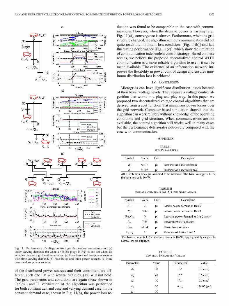
Fig. 11. Performance of voltage control algorithm without communication: (a)under varying demand; (b) when a vehicle plugs in Bus 4; and (c) when sixvehicles plug on a grid with nine buses. (a) Four buses and two power sourceswith time varying demand. (b) Four buses and three power sources. (c) Ninebuses and six power sources.
of the distributed power sources and their controllers are dif-ferent, such one PV with several vehicles, (15) will not hold.The grid parameters and conditions are again those shown inTables I and II. Verification of the algorithm was performedfor both constant demand case and varying demand case. In theconstant demand case, shown in Fig. 11(b), the power loss re-
duction was found to be comparable to the case with commu-nications. However, when the demand power is varying [e.g.,Fig. 11(a)], convergence is slower. Furthermore, when the gridstructure changed, the algorithmwithout communication did notquite reach the minimum loss conditions [Fig. 11(b)] and hadfluctuating performance [Fig. 11(c)], which show the limitationof communication independent control strategy. Based on theseresults, we believe the proposed decentralized control WITHcommunication is a more reliable algorithm to use if it can bemade available. The existence of an information network im-proves the flexibility in power control design and ensures min-imum distribution loss is achieved.
IV. CONCLUSION
Microgrids can have significant distribution losses becauseof their lower voltage levels. They require a voltage control al-gorithm that works in a plug-and-play way. In this paper, weproposed two decentralized voltage control algorithms that arederived from a cost function that minimizes power losses overthe grid network. Computer based simulation showed that thealgorithm can work reliably without knowledge of the operatingconditions and grid structure. When communications are notavailable, the control algorithm still works well in many casesbut the performance deteriorates noticeably compared with thecase with communication.
APPENDIX
TABLE IGRID PARAMETERS
TABLE IIINITIAL CONDITIONS FOR ALL THE SIMULATIONS
TABLE IIICONTROL PARAMETER VALUES

1304 IEEE TRANSACTIONS ON SMART GRID, VOL. 4, NO. 3, SEPTEMBER 2013
REFERENCES[1] R. Lasseter, A. Akhil, C. Marnay, J. Stephens, J. Dagle, R. Guttromson,
A. S. Meliopoulous, R. Yinger, and J. Eto, “Integration of distributedenergy resources: The CERTSmicrogrid concept,” U.S. Department ofEnergy and California Energy Commission, LBNL-50829, 2002.
[2] N. Hatziargyriou, H. Asano, R. Iravani, and C. Marnay, “Microgrids,”IEEE Power Energy Mag., vol. 5, pp. 78–94, Jul./Aug. 2007.
[3] R. H. Lasseter and P. Paigi, “Microgrid: A conceptual solution,” inProc. IEEE Power Electron. Specialists Conf., Aachen, Germany,2004, pp. 4285–4290.
[4] J. M. Guerrero, “Microgrids: Integration of distributed energy re-sources into the smart-grid,” in Proc. IEEE Int. Symp. Ind. Electron.,Bari, Italy, 2010, pp. 4281–4414.
[5] D. S. Eady, S. B. Siegel, R. S. Bell, and S. H. Dicke, “Sustain the Mis-sion Project: Casualty factors for fuel and water resupply convoys,”Army Environmental Policy Institute, Arlington, VA, USA, Final Tech.Rep. CTC-CR-2009-163, 2009.
[6] G. Baffet, A. Charara, and D. Lechner, “Estimation of vehicle sideslip,tire force and wheel cornering stiffness,” Control Eng. Practice, vol.17, pp. 1255–1264, Nov. 2009.
[7] “Army energy security implementation strategy,” U.S. Army. Wash-ington, DC, USA, 2009.
[8] W. Kempton and J. Tomic, “Vehicle-to-grid power implementation:From stabilizing the grid to supporting large-scale renewable energy,”J. Power Sources, vol. 144, pp. 280–294, 2005.
[9] T. Ersal, C. Ahn, I. A. Hiskens, H. Peng, and J. L. Stein, “Impact ofcontrolled plug-in EVs on microgrids: A military microgrid example,”in Proc. IEEE Power Energy Soc. Gen. Meet., Detroit, MI, USA, 2011,pp. 1–7.
[10] C. Ahn, C.-T. Li, and H. Peng, “Optimal decentralized charging controlalgorithm for electrified vehicles connected to smart grid,” J. PowerSources, vol. 196, pp. 10369–10379, Dec. 2011.
[11] K. De Brabandere, B. Bolsens, J. Van den Keybus, A. Woyte, J.Driesen, R. Belmans, and K. U. Leuven, “A voltage and frequencydroop control method for parallel inverters,” in Proc. IEEE PowerElectron. Specialists Conf., Aachen, Germany, 2004, pp. 2501–2507.
[12] A. Engler and N. Soultanis, “Droop control in LV-grids,” in Proc. Int.Conf. Future Power Syst., Amsterdam, The Netherlands, 2005, pp. 1–6.
[13] M. Tokudome, K. Tanaka, T. Senjyu, A. Yona, T. Funabashi, and K.Chul-Hwan, “Frequency and voltage control of small power systems bydecentralized controllable loads,” in Proc. Int. Conf. Power Electron.Drive Syst., Taipei, Taiwan, 2009, pp. 666–671.
[14] J. M. Guerrero, J. C. Vasquez, J. Matas, L. G. de Vicuna, and M.Castilla, “Hierarchical control of droop-controlled AC and DC micro-grids—A general approach toward standardization,” IEEE Trans. Ind.Electron., vol. 58, pp. 158–172, Jan. 2011.
[15] A. Kishore and E. F. Hill, “Static optimization of reactive powersources by use of sensitivity parameters,” IEEE Trans. Power App.Syst., vol. PAS-90, pp. 1166–1173, 1971.
[16] D. T. W. Sun and R. R. Shoults, “A preventive strategy method forvoltage and reactive power dispatch,” IEEE Trans. Power App. Syst.,vol. PAS-104, pp. 1670–1676, 1985.
[17] S. Granville, “Optimal reactive dispatch through interior pointmethods,” IEEE Trans. Power Syst., vol. 9, pp. 136–146, 1994.
[18] H. Yoshida, K. Kawata, Y. Fukuyama, S. Takayama, and Y. Nakanishi,“A particle swarm optimization for reactive power and voltage controlconsidering voltage security assessment,” IEEE Trans. Power Syst.,vol. 15, pp. 1232–1239, Nov. 2000.
[19] J. C. Vasquez, R. A. Mastromauro, J. M. Guerrero, and M. Liserre,“Voltage support provided by a droop-controlled multifunctional in-verter,” IEEE Trans. Ind. Electron., vol. 56, pp. 4510–4519, 2009.
[20] R. A. Mastromauro, M. Liserre, T. Kerekes, and A. Dell’Aquila, “Asingle-phase voltage-controlled grid-connected photovoltaic systemwith power quality conditioner functionality,” IEEE Trans. Ind.Electron., vol. 56, pp. 4436–4444, 2009.
[21] M. Braun, “Reactive power supply by distributed generators,” in Proc.IEEE Power Energy Soc. Gen. Meet., Pittsburgh, PA, USA, 2008, pp.1–8.
[22] A. Cagnano, F. Torelli, F. Alfonzetti, and E. De Tuglie, “Can PV plantsprovide a reactive power ancillary service? A treat offered by an on-linecontroller,” Renewable Energy, vol. 36, pp. 1047–1052, Mar. 2011.
[23] M. Braun, “Reactive power supplied by PV inverters—Cost-benefitanalysis,” inProc. Eur. Photovoltaic Solar Energy Conf. Exhib., Milan,Italy, 2007, pp. 1–7.
[24] K. Tanaka, T. Senjyu, S. Toma, A. Yona, T. Funabashi, and C.-H. Kim,“Decentralized voltage control in distribution systems by controllingreactive power of inverters,” in Proc. IEEE Int. Symp. Ind. Electron.,Seoul, Korea, 2009, pp. 1385–1390.
[25] A. Cagnano, T. De Tuglie, M. Liserre, and R. A.Mastromauro, “Onlineoptimal reactive power control strategy of PV-inverters,” IEEE Trans.Ind. Electron., vol. 58, pp. 4549–4558, Oct. 2011.
[26] I. A. Hiskens and E. M. Fleming, “Control of inverter-connectedsources in autonomous microgrids,” in Proc. Amer. Control Conf.,Seattle, WA, USA, 2008, pp. 586–590.
Changsun Ahn received the B.S. and M.S. degreesfrom Seoul National University, Korea, in 1999 and2005, respectively, and the Ph.D. degree from theUniversity of Michigan, Ann Arbor, MI, USA, in2011, all in mechanical engineering.He is a Senior Researcher in Korea Institute ofMa-
chinery and Materials, Daejon, South Korea. His re-search interests include the fields of automotive con-trol/estimation and energy system control. Recently,he focuses on the energy flow control of smart gridsand microgrids especially having plug in electric ve-
hicles.
Huei Peng received his Ph.D. from the University ofCalifornia, Berkeley, Ca, USA, in 1992. He is cur-rently a Professor at the Department of MechanicalEngineering, and the Executive Director of Interdis-ciplinary and Professional Engineering, at the Uni-versity of Michigan, Ann Arbor, MI, USA. His re-search interests include adaptive control and optimalcontrol, with emphasis on their applications to vehic-ular and transportation systems. His current researchfocuses include design and control of hybrid electricvehicles and vehicle active safety systems.
Dr. Peng has been an active member of the Society of Automotive Engi-neers (SAE) and the ASME Dynamic System and Control Division (DSCD).He served as the chair of the ASME DSCD Transportation Panel from 1995 to1997, and is a member of the Executive Committee of ASMEDSCD. He servedas an Associate Editor for the IEEE/ASME Transactions on Mechatronics from1998–2004 and for the ASME Journal of Dynamic Systems, Measurement andControl from 2004–2009. He received the National Science Foundation (NSF)Career award in 1998. He is an ASME Fellow.