ieee trial-use standard definitions for the...
TRANSCRIPT

The Institute of Electrical and Electronics Engineers, Inc.3 Park Avenue, New York, NY 10016-5997, USA
Copyright © 2000 by the Institute of Electrical and Electronics Engineers, Inc.All rights reserved. Published 21 June 2000. Printed in the United States of America.
Print:
ISBN 0-7381-1962-8 SH94823
PDF:
ISBN 0-7381-1963-6 SS94823
No part of this publication may be reproduced in any form, in an electronic retrieval system or otherwise, without the prior written permission of the publisher.
IEEE Std 1459-2000
IEEE Trial-Use Standard Definitions for the Measurement of Electric Power Quantities Under Sinusoidal, Nonsinusoidal, Balanced, or Unbalanced Conditions
Sponsor
Power System Instrumentation and Measurements Committeeof theIEEE Power Engineering Society
Approved 30 January 2000
IEEE-SA Standards Board
Abstract:
This is a trial-use standard for definitions used for measurement of electric powerquantities under sinusoidal, nonsinusoidal, balanced, or unbalanced conditions. It lists themathematical expressions that were used in the past, as well as new expressions, and explainsthe features of the new definitions.
Keywords:
active power, apparent power, nonactive power, power factor, reactive power, totalharmonic distortion
Authorized licensed use limited to: IEEE Xplore. Downloaded on April 20, 2011 at 03:01 from IEEE Xplore. Restrictions apply.

IEEE Standards
documents are developed within the IEEE Societies and the Standards Coordinating Com-mittees of the IEEE Standards Association (IEEE-SA) Standards Board. Members of the committees servevoluntarily and without compensation. They are not necessarily members of the Institute. The standardsdeveloped within IEEE represent a consensus of the broad expertise on the subject within the Institute aswell as those activities outside of IEEE that have expressed an interest in participating in the development ofthe standard.
Use of an IEEE Standard is wholly voluntary. The existence of an IEEE Standard does not imply that thereare no other ways to produce, test, measure, purchase, market, or provide other goods and services related tothe scope of the IEEE Standard. Furthermore, the viewpoint expressed at the time a standard is approved andissued is subject to change brought about through developments in the state of the art and commentsreceived from users of the standard. Every IEEE Standard is subjected to review at least every five years forrevision or reaffirmation. When a document is more than five years old and has not been reaffirmed, it is rea-sonable to conclude that its contents, although still of some value, do not wholly reflect the present state ofthe art. Users are cautioned to check to determine that they have the latest edition of any IEEE Standard.
Comments for revision of IEEE Standards are welcome from any interested party, regardless of membershipaffiliation with IEEE. Suggestions for changes in documents should be in the form of a proposed change oftext, together with appropriate supporting comments.
Interpretations: Occasionally questions may arise regarding the meaning of portions of standards as theyrelate to specific applications. When the need for interpretations is brought to the attention of IEEE, theInstitute will initiate action to prepare appropriate responses. Since IEEE Standards represent a consensus ofall concerned interests, it is important to ensure that any interpretation has also received the concurrence of abalance of interests. For this reason, IEEE and the members of its societies and Standards CoordinatingCommittees are not able to provide an instant response to interpretation requests except in those cases wherethe matter has previously received formal consideration.
Comments on standards and requests for interpretations should be addressed to:
Secretary, IEEE-SA Standards Board445 Hoes LaneP.O. Box 1331Piscataway, NJ 08855-1331USA
IEEE is the sole entity that may authorize the use of certification marks, trademarks, or other designations toindicate compliance with the materials set forth herein.
Authorization to photocopy portions of any individual standard for internal or personal use is granted by theInstitute of Electrical and Electronics Engineers, Inc., provided that the appropriate fee is paid to CopyrightClearance Center. To arrange for payment of licensing fee, please contact Copyright Clearance Center, Cus-tomer Service, 222 Rosewood Drive, Danvers, MA 01923 USA; (978) 750-8400. Permission to photocopyportions of any individual standard for educational classroom use can also be obtained through the Copy-right Clearance Center.
Note: Attention is called to the possibility that implementation of this standard mayrequire use of subject matter covered by patent rights. By publication of this standard,no position is taken with respect to the existence or validity of any patent rights inconnection therewith. The IEEE shall not be responsible for identifying patents forwhich a license may be required by an IEEE standard or for conducting inquiries intothe legal validity or scope of those patents that are brought to its attention.
Authorized licensed use limited to: IEEE Xplore. Downloaded on April 20, 2011 at 03:01 from IEEE Xplore. Restrictions apply.

Copyright © 2000 IEEE. All rights reserved.
iii
Introduction
(This introduction is not part of IEEE Std 1459-2000, IEEE Trial-Use Standard Definitions for theMeasurement of Electric Power Quantities Under Sinusoidal, Nonsinusoidal, Balanced, or UnbalancedConditions.)
The definitions for active, reactive, and apparent powers that are currently used are based on the knowledgedeveloped and agreed upon during the 1940s. Such definitions served the industry well, as long as the cur-rent and voltage waveforms remained nearly sinusoidal.
Important changes have occurred in the last 50 years. The new environment is conditioned by the followingfacts:
a) Power electronics equipment, such as Adjustable Speed Drives, Controlled Rectifiers, Cycloconvert-ers, Electronically Ballasted Lamps, Arc and Induction Furnaces, and clusters of PersonalComputers, represent major nonlinear and parametric loads proliferating among industrial and com-mercial customers. Such loads have the potential to create a host of disturbances for the utility andthe end-user’s equipment. The main problems stem from the flow of nonactive energy caused by har-monic currents and voltages.
b) New definitions of powers have been discussed in the last 30 years in the engineering literature(Filipski [B6]). The mechanism of electric energy flow for nonsinusoidal and/or unbalancedconditions is well understood today.
c) The traditional instrumentation designed for the sinusoidal 60/50 Hz waveform is prone tosignificant errors when the current and the voltage waveforms are distorted (Filipski [B6]).
d) Microprocessors and minicomputers enable today’s manufacturers of electrical instruments to con-struct new, accurate, and versatile metering equipment that is capable of measuring electricalquantities defined by means of advanced mathematical models.
e) There is a need to quantify correctly the distortions caused by the nonlinear and parametric loads,and to apply a fair distribution of the financial burden required to maintain the quality of electricservice.
This trial-use standard lists new definitions of powers needed for the following particular situations:
— When the voltage and current waveforms are nonsinusoidal.
— When the load is unbalanced or the supplying voltages are asymmetrical.
— When the energy dissipated in the neutral path due to zero-sequence current components haseconomical significance.
The new definitions were developed to give guidance with respect to the quantities that should be measuredor monitored for revenue purposes, engineering economic decisions, and determination of major harmonicpolluters. The following important electrical quantities are recognized by this trial-use standard:
1) The power frequency (60/50 Hz or fundamental) apparent, active, and reactive powers. These threebasic quantities are the quintessence of the power flow in electric networks. They define the productgenerated, transmitted, distributed, and sold by the electric utilities and bought by the end-users. Thisis the electric energy transmitted by the 60/50 Hz electromagnetic field. In poly-phase systems thepower frequency positive-sequence powers are the important dominant quantities. The power fre-quency positive-sequence power factor is a key value that helps determine and adjust the flow ofpower frequency positive-sequence reactive power. The fundamental positive-sequence reactivepower is of utmost importance in power systems; it governs the fundamental voltage magnitude andits distribution along the feeders, and affects electromechanical stability as well as the energy loss.
Authorized licensed use limited to: IEEE Xplore. Downloaded on April 20, 2011 at 03:01 from IEEE Xplore. Restrictions apply.

iv
Copyright © 2000 IEEE. All rights reserved.
2) The effective apparent power in three-phase systems, , where
V
e
and
I
e
are the equivalentvoltage and current. In sinusoidal and balanced situations,
S
e
is equal to the conventional apparentpower , where and are the line-to-neutral and the line-to-linevoltage, respectively. For sinusoidal unbalanced or for nonsinusoidal balanced or unbalanced situa-tions,
S
e
allows rational and correct computation of the power factor. This quantity was proposed in1922 by the German engineer F. Buchholz [B1] and in 1933 was explained by the American engineerW. M. Goodhue [B7].
3) The non-60 Hz or nonfundamental apparent power,
S
N
(for brevity, 50 Hz power is not always men-tioned). This power quantifies the overall amount of harmonic pollution delivered or absorbed by aload. It also quantifies the required capacity of dynamic compensators or active filters when used fornonfundamental compensation alone.
4) Current distortion power,
D
I
, identifies the segment of nonfundamental nonactive power due to cur-rent distortion. This is usually the dominant component of
S
N
.
5) Voltage distortion power,
D
V
, separates the nonfundamental nonactive power component due to volt-age distortion.
6) Apparent harmonic power,
S
H
, indicates the level of apparent power due to harmonic voltages andcurrents alone. This is the smallest component of
S
N
and includes the harmonic active power
P
H
.
To avoid confusion, it was decided not to add new units. The use of the watts (W) for instantaneous andactive powers, volt-amperes (VA) for apparent powers, and varistor (var) for all the nonactive powers, main-tains the distinct separation among these three major types of powers.
There is not yet available a generalized power theory that can provide a simultaneous common base for
— Energy billing
— Evaluation of electric energy quality
— Detection of the major sources of waveform distortion
— Theoretical calculations for the design of mitigation equipment such as active filters or dynamic-compensators
This trial-use standard is meant to provide definitions extended from the well-established concepts. It ismeant to serve the user who wants to measure and design instrumentation for energy and power quantifica-tion. It is not meant to help in the design of real-time control of dynamic compensators or for diagnosisinstrumentation used to pinpoint to a specific type of annoying event or harmonic.
To the working group’s knowledge, no commercially available instruments are fully capable of quantifying
S
e
and
S
N
according to the definitions given in this standard. These definitions are meant to serve as a guide-line and a useful benchmark for future developments.
Se 3V eIe=
S 3V lnI 3V llI= = V ln V ll
Publication of this trial-use standard for comment and criticism has been approved by the Institute ofElectrical and Electronics Engineers. Trial-use standards are effective for 24 months from the date ofpublication. Comments for revision will be accepted for 18 months after publication. Suggestions forrevision should be directed to the Secretary, IEEE-SA Standards Board, 445 Hoes Lane, P.O. Box 1331,Piscataway, NJ 08855-1331, and should be received no later than 21 November 2001. It is expected thatfollowing the 24-month period, this trial-use standard, revised as necessary, shall be submitted to theIEEE-SA Standards Board for approval as a full-use standard.
Authorized licensed use limited to: IEEE Xplore. Downloaded on April 20, 2011 at 03:01 from IEEE Xplore. Restrictions apply.

Copyright © 2000 IEEE. All rights reserved.
v
Participants
At the time this trial-use standard was completed, the Working Group on Nonsinusoidal Situations had thefollowing membership:
Alexander E. Emanuel,
Chair
The following members of the balloting committee voted on this standard:
When the IEEE-SA Standards Board approved this standard on 30 January 2000, it had the followingmembership:
Richard J. Holleman,
Chair
Donald N. Heirman,
Vice Chair
Judith Gorman,
Secretary
*Member Emeritus
Also included is the following nonvoting IEEE-SA Standards Board liaison:
Robert E. Hebner
Catherine K.N. Berger
IEEE Standards Project Editor
Rejean ArseneauYahia BagzouzJoseph M. BelangerKeneth B. BowesJames A. BraunDavid CooperMikey D. CoxAlexander Domijan
Larry DuranteDavid ElmoreLazhar Fekih-AhmedPiotr S. FilipskiPrasanta K. GhoshErich GuntherDennis HansenGilbert C. HensleyOle W. Iwanusiw
Dan McAuliffTerrence McCombAlexander McEachernHerman M. MillicanThomas L. Nelson George StephensRaymond H. StevensDouglas Williams
Warren A. AndersonWilliam J. BuckleySteven W. CramptonAlexander E. EmanuelErich Gunther
Ernst HaniqueDennis HansenJohn KuffelWilliam LarzelereBlane LeuschnerTerrence McComb
Herman M. MillicanDaleep C. MohlaEddy SoRao ThallamBarry H. Ward
Satish K. AggarwalDennis BodsonMark D. BowmanJames T. CarloGary R. EngmannHarold E. EpsteinJay Forster*Ruben D. Garzon
James H. GurneyLowell G. JohnsonRobert J. KennellyE. G. “Al” KienerJoseph L. Koepfinger*L. Bruce McClungDaleep C. MohlaRobert F. Munzner
Louis-François PauRonald C. PetersenGerald H. PetersonJohn B. PoseyGary S. RobinsonAkio TojoHans E. WeinrichDonald W. Zipse
Authorized licensed use limited to: IEEE Xplore. Downloaded on April 20, 2011 at 03:01 from IEEE Xplore. Restrictions apply.

vi
Copyright © 2000 IEEE. All rights reserved.
Contents
1. Overview.............................................................................................................................................. 1
1.1 Scope............................................................................................................................................ 11.2 Purpose......................................................................................................................................... 1
2. References............................................................................................................................................ 2
3. Definitions............................................................................................................................................ 2
3.1 Single-Phase................................................................................................................................. 23.2 Three-Phase systems.................................................................................................................. 10
Annex A (informative) Theoretical examples............................................................................................. 28
Annex B (informative) Practical studies and measurements ...................................................................... 39
Annex C (informative) Bibliography .......................................................................................................... 44
Authorized licensed use limited to: IEEE Xplore. Downloaded on April 20, 2011 at 03:01 from IEEE Xplore. Restrictions apply.

Copyright © 2000 IEEE. All rights reserved.
1
IEEE Trial-Use Standard Definitions for the Measurement of Electric Power Quantities Under Sinusoidal, Nonsinusoidal, Balanced, or Unbalanced Conditions
1. Overview
This trial-use standard is divided into three clauses. Clause 1 lists the scope of this document. Clause 2 listsreferences to other standards that are useful in applying this trial-use standard. Clause 3 provides the defini-tions, among which there are several new expressions.
The preferred mathematical expressions recommended for the instrumentation design are marked with asign. The additional expressions are meant to reinforce the theoretical approach and facilitate a better
understanding of the explained concepts.
1.1 Scope
This is a trial-use standard for definitions used for measurement of electric power quantities under sinusoi-dal, nonsinusoidal, balanced, or unbalanced conditions. It lists the mathematical expressions that were usedin the past, as well as new expressions, and explains the features of the new definitions.
1.2 Purpose
This trial-use standard is meant to provide organizations with criteria for designing and using meteringinstrumentation.
||
Authorized licensed use limited to: IEEE Xplore. Downloaded on April 20, 2011 at 03:01 from IEEE Xplore. Restrictions apply.

IEEEStd 1459-2000 IEEE TRIAL-USE STD DEFINITIONS FOR MEASUREMENT OF ELECTRIC POWER QUANTITIES
2
Copyright © 2000 IEEE. All rights reserved.
2. References
This trial-use standard shall be used in conjunction with the following publications. If the following publica-tions are superseded by an approved revision, the revision shall apply.
DIN 40110-1997, Quantities Used in Alternating Current Theory.
1
IEEE Std 280-1985 (Reaff 1997), IEEE Standard Letter Symbols for Quantities Used in Electrical Scienceand Electrical Engineering.
2
ISO 31-5:1992, Quantities and Units—Part 5: Electricity and Magnetism.
3
3. Definitions
Mathematical expressions that are considered appropriate for instrumentation design are marked with thesign When the sign appears on the right side, it means that the last expression that is listed isfavored. Each descriptor of a power type is followed by its measurement unit in parentheses.
3.1 Single-Phase
3.1.1 Single-Phase sinusoidal
A sinusoidal voltage source
supplying a linear load, will produce a sinusoidal current of
where
V
is the rms value of the voltage (V)
I
is the rms value of the current (A)
ω
is the angular frequency 2
π
f
(rad/s)
f
is the frequency (Hz)
θ
is the phase angle (rad)
t
is the time (s)
1
DIN publications are available from the Deutsches Institut für Normung, Burggrafenstrasse 6, Postfach 1107, 12623 Berlin 30, Ger-many (011 49 30 260 1362).
2
IEEE publications are available from the Institute of Electrical and Electronics Engineers, 445 Hoes Lane, P.O. Box 1331, Piscataway,NJ 08855-1331, USA (http://standards.ieee.org/).
3
ISO publications are available from the ISO Central Secretariat, Case Postale 56, 1 rue de Varembé, CH-1211, Genève 20, Switzer-land/Suisse (http://www.iso.ch/). ISO publications are also available in the United States from the Sales Department, AmericanNational Standards Institute, 11 West 42nd Street, 13th Floor, New York, NY 10036, USA (http://www.ansi.org/).
.|| ||
v 2V sin ωt( )=
i 2I sin ωt θ–( )=
Authorized licensed use limited to: IEEE Xplore. Downloaded on April 20, 2011 at 03:01 from IEEE Xplore. Restrictions apply.

IEEEUNDER SINUSOIDAL, NONSINUSOIDAL, BALANCED, OR UNBALANCED CONDITIONS Std 1459-2000
Copyright © 2000 IEEE. All rights reserved.
3
3.1.1.1 Instantaneous power (W)
The instantaneous power
p
is given by
where
p
a
= ; P =
p
q
= ;
Q
=
NOTES
1—The instantaneous power is produced by the active component of the current, i.e., the component that is in phase withthe voltage. It is the rate of flow of the energy
This energy flows unidirectionally from the source to the load. Its rate of flow is not negative,
p
a
≥
0
.
2—The instantaneous power
p
q
is produced by the reactive component of the current, i.e., the component that is inquadrature with the voltage. It is the rate of flow of the energy
This type of energy oscillates between the source and inductances, capacitances, and moving masses pertaining to elec-tromechanical systems (motor and generator rotors, plungers, and armatures). The average value of this rate of flow iszero, and the net transfer of energy to the load is nil.
3.1.1.2 Active power (W)
The active power
P
is the mean value of the instantaneous power during the observation time interval
τ
to
τ
+
kT
where
T
= 1/
f
is the cycle (s),
k
is an integer number,
τ
is the moment when the measurement starts.
3.1.1.3 Reactive power (var)
The reactive power
Q
is the amplitude of the oscillating instantaneous power
p
q
.
NOTE— If the load is inductive, then
Q
> 0. If the load is capacitive, then
Q
< 0.
p|| vi=
p pa pq+=
VI θ 1 2ωt( )cos–[ ]cos P 1 2ωt( )cos–[ ]= VI θcos
VI θ 2ωt( )sinsin– Q 2ωt( )sin–= VI θsin
wa pa td∫ PtP
2ω------- 2ωt( )sin–= =
wq pq td∫Q
2ω------- 2ωt( )cos= =
P|| 1kT------ p td
τ
τ kT+
∫=
P|| VIcosθ=
Q1
2π------ vdi∫°
1–2π------ idv∫°
1kT------ v
iddt---- td
τ
τ kT+
∫1–
kT------ i
vddt----- td
τ
τ kT+
∫ω–
kT------- v i td∫[ ] td
τ
τ kT+
∫= = = = =
Q|| ωkT------ i v td∫[ ]
τ
τ kT+
∫= dt
Q VI θsin=
Authorized licensed use limited to: IEEE Xplore. Downloaded on April 20, 2011 at 03:01 from IEEE Xplore. Restrictions apply.

IEEEStd 1459-2000 IEEE TRIAL-USE STD DEFINITIONS FOR MEASUREMENT OF ELECTRIC POWER QUANTITIES
4 Copyright © 2000 IEEE. All rights reserved.
3.1.1.4 Apparent power (VA)
The apparent power S is the product of the root-mean-square (rms) voltage and the root-mean-square (rms)current.
NOTE—Instantaneous power p follows a sinusoidal oscillation with a frequency biased by the activepower P. The amplitude of the sinusoidal oscillation is the apparent power S.
3.1.1.5 Power factor
3.1.1.6 Complex power (VA)
where
is the voltage phasor,
is the conjugated current phasor.
This expression stems from the power triangle, S, P, Q, and is useful in power flow studies. Figure 1 summa-rizes the conventional power flow directions as interpreted in literature (Stevens [B12]4).
3.1.2 Single-Phase nonsinusoidal
For steady-state conditions a nonsinusoidal instantaneous voltage or current has two distinctive components:the power system frequency components v1 and i1, and the remaining terms vH and iH that contains all inte-ger and noninteger number harmonics.
4The numbers in brackets correspond to those of the bibliography in Annex C.
S|| VI=
S P2 Q2+=
2 f 2ω 2π⁄=
PF|| PS---=
S V I∗ P jQ+= =
V V 0°∠=
I∗ I θ∠=
v1 2V 1 ωt α1–( )sin=
i1 2I1 ωt β1–( )sin=
vH 2 V h hωt αh–( )sinh 1≠∑=
iH 2 Ih hωt βh–( )sinh 1≠∑=
Authorized licensed use limited to: IEEE Xplore. Downloaded on April 20, 2011 at 03:01 from IEEE Xplore. Restrictions apply.

IEEEUNDER SINUSOIDAL, NONSINUSOIDAL, BALANCED, OR UNBALANCED CONDITIONS Std 1459-2000
Copyright © 2000 IEEE. All rights reserved. 5
The corresponding rms values squared are as follows:
where
=
=
NOTE—The direct voltage and the direct current terms V0 and I0, obtained for h = 0, must be included in VH and IH.
They correspond to a hypothetical ; . Significant
dc components are rarely present in ac power systems; however, traces of dc are not uncommon.
Figure 1—Four-quadrant power flow directions (see [B12])
Copyright 1983 IEEE
V 2 1kT------ v2 td
τ
τ kT+
∫ V 12 V H
2+= =
I2 1kT------ i2 td
τ
τ kT+
∫ I12 IH
2+= =
V H2 V h
2
h 1≠∑ V 2 V 1
2–= ||
IH2 Ih
2
h 1≠∑ I2 I1
2–= ||
α0 β0 45°–= = (sin(–α0 ) sin β0–( ) sin 45° 1/ 2 )= = =
Authorized licensed use limited to: IEEE Xplore. Downloaded on April 20, 2011 at 03:01 from IEEE Xplore. Restrictions apply.

IEEEStd 1459-2000 IEEE TRIAL-USE STD DEFINITIONS FOR MEASUREMENT OF ELECTRIC POWER QUANTITIES
6 Copyright © 2000 IEEE. All rights reserved.
3.1.2.1 Total harmonic distortion
The overall deviation of a distorted wave from its fundamental can be estimated with the help of the totalharmonic distortion. The total harmonic distortion of the voltage is as follows:
The total harmonic distortion of the current is as follows:
3.1.2.2 Instantaneous power (W)
where
pa =
is a term that contains all the components that have non-zero average value, and
is a term that does not contribute to the net transfer of energy, i.e., its average value is nil.
The angle is the phase angle between the phasors Vh and Ih.
3.1.2.3 Active power (W)
3.1.2.4 Fundamental or 60 Hz active power (W)
3.1.2.5 Harmonic active power (W)
NOTE—For ac motors, which make up the vast majority of loads, the harmonic active power is not a useful power. Con-sequently, it is useful to separate the fundamental active power P1 from the harmonic active power PH.
THDv||V H
V 1-------
VV 1------ 2
1–= =
THDI||IH
I1-----
II1---- 2
1–= =
p vi=
p pa pq+=
V hIh θh 1 2hωt( )cos–[ ]cosh∑
pq V hIh θh 2hωt( ) 2V mIn mωt αm+( ) nωt βn+( )sinsinm n≠
m n 1≠,
∑+sinsinh∑=
θh βh αh–=
P|| 1kT------ p td
τ
τ kT+
∫=
P P1 PH+=
P1|| 1kT------ v1i1 td
τ
τ kT+
∫ V 1I1 θ1cos= =
PH V hIh θhcosh 1≠∑ P P1 ||–= =
Authorized licensed use limited to: IEEE Xplore. Downloaded on April 20, 2011 at 03:01 from IEEE Xplore. Restrictions apply.
IEEEUNDER SINUSOIDAL, NONSINUSOIDAL, BALANCED, OR UNBALANCED CONDITIONS Std 1459-2000
Copyright © 2000 IEEE. All rights reserved. 7
3.1.2.6 Fundamental reactive power (var)
3.1.2.7 Budeanu’s reactive power (var)
where
QBH =
NOTE—The usefulness of QB for quantifying the flow of harmonic nonactive power has been questioned by many engi-neers (Czarnecki [B2], Lyon [B10]). Field measurements and simulations (Pretorius, van Wyk, and Swart [B11]) provethat in many situations QBH < 0, thus leading to situations where QB < Q1.
3.1.2.8 Apparent power (VA)
NOTE—An important practical property of S is that the power loss ∆P, in the feeder that supplies the apparent power S,is a nearly linear function of S2 (Emanuel [B4]).
where
R is an equivalent shunt resistance, representing transformer core losses and cable dielectric losses, re is the effective Thevenin resistance. Theoretically re can be obtained from the equivalence of losses
as follows:
where
Ksh is the skin effect coefficient for the h harmonic,rdc is the Thevenin dc resistance (Ω).
Q1||ω1
kT------ i1 v1 td∫[ ] td
τ
τ kT+
∫=
V 1I1 θ1sin=
QB V hIh θhsinh∑=
QB Q1 QBH+=
V hIh θhsinh 1≠∑
S|| VI=
∆Pre
V 2------S2 V 2
R------+=
reI2 rdc KshIh2
h∑=
Authorized licensed use limited to: IEEE Xplore. Downloaded on April 20, 2011 at 03:01 from IEEE Xplore. Restrictions apply.

IEEEStd 1459-2000 IEEE TRIAL-USE STD DEFINITIONS FOR MEASUREMENT OF ELECTRIC POWER QUANTITIES
8 Copyright © 2000 IEEE. All rights reserved.
3.1.2.9 Fundamental or 60/50 Hz apparent power (VA)
Fundamental apparent power S1 and its components P1 and Q1 are the actual quantities that help define therate of flow of the electromagnetic field energy associated with the 60/50 Hz voltage and current. This is aproduct of high interest for both the utility and the end-user.
3.1.2.10 Nonfundamental apparent power (VA)
The separation of the rms current and voltage into fundamental and harmonic terms (see 3.1.2) resolves theapparent power in the following manner (Emanuel [B5]):
is the nonfundamental apparent power, and is resolved in the following three distinctive terms:
3.1.2.11 Current distortion power (var)
3.1.2.12 Voltage distortion power (var)
3.1.2.13 Harmonic apparent power (VA)
3.1.2.14 Harmonic distortion Power (var)
NOTE—In practical power systems, THDV < THDI and SN can be computed using the following expression (Emanuel[B5]):
When THDV ≤ 5% and THDI≤ 200%, this expression yields an error less than 0.15%.
S1|| V 1I1=
S12 P1
2 Q12+=
S2 VI( )2 V 12 V H
2+( ) I12 IH
2+( ) V 1I1( )2 V 1IH( )2 V HI1( )2 V HIH( )2 S12 SN
2+( )=+ + += = =
SN|| S2 S12–=
SN2 D1
2 Dv2 SH
2+ +=
DI V 1IH S1 THDI( ) ||= =
Dv V HI1 S1 THDV( ) ||= =
SH V HIH S1 THD1( ) THDV( ) ||= =
SH PH2 DH
2+=
DH|| SH2 PH
2–=
SN S1 THDI( )2 THDV( )2+≈
Authorized licensed use limited to: IEEE Xplore. Downloaded on April 20, 2011 at 03:01 from IEEE Xplore. Restrictions apply.

IEEEUNDER SINUSOIDAL, NONSINUSOIDAL, BALANCED, OR UNBALANCED CONDITIONS Std 1459-2000
Copyright © 2000 IEEE. All rights reserved. 9
For THDV < 5% and THDI > 40%, an error less than 1.00% is obtained using the following expression (Emanuel [B5]):
3.1.2.15 Nonactive power (var)
This power lumps together both fundamental and nonfundamental nonactive components. In the past, thispower was called fictitious power.
3.1.2.16 Budeanu’s distortion power (var)
This power results from the resolution of S using Budeanu’s reactive power QB (see 3.1.2.7) that leads to thefollowing:
hence,
NOTE—This distortion power is affected by the deficiency of QB (Pretorius, van Wyk, and Swart [B11]).
3.1.2.17 Fundamental or 60/50 Hz power factor
This ratio helps evaluate separately the fundamental power flow conditions. It can be called the fundamentalpower factor or 60/50 Hz power factor. It is also often referred to as the displacement power factor.
3.1.2.18 Power factor
NOTES
1—The apparent power S can be viewed as the maximum active power that can be transmitted to a load while keeping itsload voltage V constant and line losses constant. The result is that for a given S and V, maximum utilization of the line isobtained when P = S; hence, the ratio P/S is a utilization factor indicator.
2—The overall degree of harmonic injection produced by a large nonlinear load, or by a group of loads or consumers,can be estimated from the ratio SN /S1. The effectiveness of harmonic filters also can be evaluated from such a measure-ment. The measurements of S1, P1, PF1, or Q1 help establish the characteristics of the fundamental power flow.
SN S1 THDI( )≈
N|| S2 P2–=
S2 P2 QB2 DB
2+ +=
DB S2 P2– QB2–=
PF1 θ1cosP1
S1------ ||= =
PF|| PS---=
PFPS---
P1 PH+
S12 SN
2+----------------------
P1 S1⁄( ) 1 PH P1⁄( )+[ ]
1 SN S1⁄( )2+--------------------------------------------------------= = =
1 PH P1⁄( )+[ ]PF1
1 THDI2 THDV
2 THDITHDV( )2+ + +------------------------------------------------------------------------------------------------=
Authorized licensed use limited to: IEEE Xplore. Downloaded on April 20, 2011 at 03:01 from IEEE Xplore. Restrictions apply.

IEEEStd 1459-2000 IEEE TRIAL-USE STD DEFINITIONS FOR MEASUREMENT OF ELECTRIC POWER QUANTITIES
10 Copyright © 2000 IEEE. All rights reserved.
3—In most common practical situations, . It is difficult to measure correctly the higher-order components ofPH with most metering instrumentation. Thus, one cannot rely on measurements of PH components when making tech-nical decisions regarding harmonics compensation, energy tariffs, or to quantify the detrimental effects made by anonlinear or parametric load to a particular power system (Emanuel [B5]; IEEE [B9]; Swart, van Wyk, and Case [B13]).
4—When THDV < 5% and THDI > 40%, it is convenient to use the following expression:
5— In typical nonsinusoidal situations, DI > DV > SH > PH.
The definitions presented in 3.1.2.8 to 3.1.2.17 are summarized in Table 1.
3.2 Three-Phase systems
3.2.1 Three-Phase sinusoidal balanced
In this case, the line-to-neutral voltages are as follows:
Table 1—Summary and grouping of the quantities in single-phase systems with nonsinusoidal waveforms
Quantity or indicator Combined 60 Hz powers
(fundamental)Non-60 Hz powers (nonfundamental)
Apparent S(VA)
S1(VA)
SN(VA)
SH(VA)
Active P(W)
P1(W)
PH(W)
Nonactive N(var)
Q1(var)
DI DV(var)
DH
Line utilization PF = P/S PF1 = P1/S1 —
Harmonic pollution — — SN /S1
PH P1«
PF1
1 THDI2+
----------------------------PF1≈
va 2V ln ωt( )sin=
vb 2V ln ωt 120°–( )sin=
vc 2V ln ωt 120°+( )sin=
Authorized licensed use limited to: IEEE Xplore. Downloaded on April 20, 2011 at 03:01 from IEEE Xplore. Restrictions apply.
IEEEUNDER SINUSOIDAL, NONSINUSOIDAL, BALANCED, OR UNBALANCED CONDITIONS Std 1459-2000
Copyright © 2000 IEEE. All rights reserved. 11
The line currents have similar expressions. They are as follows:
NOTES
1—Perfectly sinusoidal and balanced three-phase, low-voltage systems are uncommon. Only under laboratory condi-tions, using low distortion power amplifiers, is it possible to work with ac power sources with THDV < 0.1% and voltageunbalance V –/V + < 0.1%. Practical low-voltage systems will rarely operate with THDV < 1% and V –/V + < 0.4%, whereV + and V – are the positive- and negative-sequence voltages, see 3.2.2.2.1.
2— In the case of a three-wire system, the line-to-neutral voltages are defined assuming an artificial neutral node.
3.2.1.1 Instantaneous power (W)
3.2.1.2 Active power (W)
where
is line-to neutral voltage,
is line-to-line voltage.
3.2.1.3 Reactive power (var)
3.2.1.4 Apparent power (VA)
3.2.1.5 Power factor
ia 2I ωt θ–( )sin=
ib 2I ωt θ– 120°–( )sin=
ic 2I ωt θ– 120°+( )sin=
p|| vaia vbib vcic+ + P= =
P|| 1kT------ p td
τ
τ kT+
∫=
P 3V lnI θcos 3V llI θcos= =
V ln
V ll
Q 3V lnI θsin 3V llI θsin= =
Q S2 P2– ||=
S 3V lnI=|| 3V llI=
PF|| PS---=
Authorized licensed use limited to: IEEE Xplore. Downloaded on April 20, 2011 at 03:01 from IEEE Xplore. Restrictions apply.

IEEEStd 1459-2000 IEEE TRIAL-USE STD DEFINITIONS FOR MEASUREMENT OF ELECTRIC POWER QUANTITIES
12 Copyright © 2000 IEEE. All rights reserved.
3.2.2 Three-Phase sinusoidal unbalanced
In this case, the three current phasors, Ia, Ib, and Ic, do not have equal magnitudes, nor are they shiftedexactly with respect to each other. Load unbalance leads to asymmetrical currents that in turn can cause volt-age asymmetry. There are situations when the three voltage phasors are not symmetrical. This leads toasymmetrical currents even when the load is perfectly balanced.
The line-to-neutral voltages are as follows:
The line currents have similar expressions. They are as follows:
NOTE—In the case of three-wire systems, the line-to-neutral voltages are defined assuming an artificial neutral node,which can be obtained with the help of three identical resistances connected in Y.
3.2.2.1 Instantaneous power (W)
for three-wire systems where , and
where vab, vbc, and vca are the instantaneous line-to-line voltages.
3.2.2.2 Active power (W)
where
va 2V aln ωt αa+( )sin=
vb 2V bln ωt αb 120°–+( )sin=
vc 2V cln ωt αc 120°+ +( )sin=
ia 2Ia ωt βa–( )sin=
ib 2Ib ωt βb– 120°–( )sin=
ic 2Ic ωt βc– 120°+( )sin=
p|| vaia vbib vcic+ +=
ia ib ic+ + 0=
p|| vabia vcbic+ vacia vbcib+ vbaib v+ caic= = =
P|| IkT------ p td
τ
τ kT+
∫=
P|| Pa Pb Pc+ +=
Pa1
Kt------ vaia td
τ
τ kT+
∫ V alnIa θa θ a ;cos α a β a += = =
Authorized licensed use limited to: IEEE Xplore. Downloaded on April 20, 2011 at 03:01 from IEEE Xplore. Restrictions apply.

IEEEUNDER SINUSOIDAL, NONSINUSOIDAL, BALANCED, OR UNBALANCED CONDITIONS Std 1459-2000
Copyright © 2000 IEEE. All rights reserved.
13
P
a
, P
b
,
and
P
c
are phase active powers.
3.2.2.2.1 Positive-, negative-, and zero-sequence active powers (W)
In some situations the use of symmetrical components may be helpful. The symmetrical voltage components
V
+
,
V
–
,
V
0
and current components
I
+
,
I
–
,
I
0
with the respective phase angles
θ
+
, θ
–
, θ
0
yield the followingthree active power components:
The positive-sequence active power
The negative-sequence active power
The zero-sequence active power
The total active power is
3.2.2.3 Reactive power (var)
Per phase reactive powers are defined with the help of the following expressions:
For the vector apparent power
S
V
(see 3.2.2.6) the total reactive power
Q
is as follows:
NOTE—The above expression of
Q
cannot be used in conjunction with the arithmetic apparent power
S
A
, defined in
3.2.2.5.
Pb1
Kt------ vbib td
τ
τ kT+
∫ V blnIb θb θ b ;cos α b β b += = =
Pc1
Kt------ vcic td
τ
τ kT+
∫ V clnIc θc θ c ;cos α c β c += = =
P+ 3V ln+ I+ θ+cos=
P– 3V ln– I– θ–cos=
P0 3V ln0 I0 θ0cos=
P P+ P– P0+ +=
QaωkT------ ia va td∫[ ] td
τ
τ kT+
∫ V alnIa θasin= =
QbωkT------ ib vb td∫[ ] td
τ
τ kT+
∫ V blnIb θbsin= =
QcωkT------ ic vc td∫[ ] td
τ
τ kT+
∫ V clnIc θcsin= =
Q Qa Qb Qc+ +=
Authorized licensed use limited to: IEEE Xplore. Downloaded on April 20, 2011 at 03:01 from IEEE Xplore. Restrictions apply.

IEEEStd 1459-2000 IEEE TRIAL-USE STD DEFINITIONS FOR MEASUREMENT OF ELECTRIC POWER QUANTITIES
14
Copyright © 2000 IEEE. All rights reserved.
3.2.2.3.1 Positive-, negative-, and zero-sequence reactive powers (var)
In some situations the use of symmetrical components may be helpful. The three reactive powers are asfollows:
The positive-sequence reactive power
The negative-sequence reactive power
The zero-sequence reactive power
The total reactive power is
3.2.2.4 Phase apparent powers (VA)
; ;
;
3.2.2.5 Arithmetic apparent power (VA)
NOTE—The arithmetic apparent power cannot be resolved according to 3.1.1.4,
where
P =
Q =
Q+ 3V ln+ I+ θ+sin=
Q– 3V ln– I– θ–sin=
Q0 3V ln0 I0 θ0sin=
Q Q+ Q– Q0+ +=
Sa V alnIa= Sb V blnIb= Sc V clnIc=
Sa2 Pa
2 Qa2+= Sb
2 Pb2 Qb
2+= Sc2 Pc
2 Qc2+=
SA Sa Sb Sc+ +=
SA P2 Q2+≠
Pa Pb Pc+ +
Qa Qb Qc+ +
Authorized licensed use limited to: IEEE Xplore. Downloaded on April 20, 2011 at 03:01 from IEEE Xplore. Restrictions apply.

IEEEUNDER SINUSOIDAL, NONSINUSOIDAL, BALANCED, OR UNBALANCED CONDITIONS Std 1459-2000
Copyright © 2000 IEEE. All rights reserved. 15
3.2.2.6 Vector apparent power (VA)
A geometrical interpretation of SV is presented in Figure 2.
3.2.2.6.1 Positive-, negative-, and zero-sequence apparent powers (VA)
SV P2 Q2+=
SV Pa Pb Pc j Qa Qb Qc+ +( )+ + + P jQ+= =
SV P+ P– P0 j Q+ Q– Q0+ +( )+ + +=
Figure 2—Arithmetic and vector apparent powers: sinusoidal situation
SA
Sc
S+ S+ P+ jQ++= =
S– S– P– jQ–+= =
S0 S0 P0 jQ0+= =
SV S+ S– S0+ +=
SA S+ S– S0+ +≠
Authorized licensed use limited to: IEEE Xplore. Downloaded on April 20, 2011 at 03:01 from IEEE Xplore. Restrictions apply.

IEEEStd 1459-2000 IEEE TRIAL-USE STD DEFINITIONS FOR MEASUREMENT OF ELECTRIC POWER QUANTITIES
16 Copyright © 2000 IEEE. All rights reserved.
3.2.2.7 Vector power factor and arithmetic power factor
NOTE—A three-phase line supplying one or more customers should be viewed as one single path, one entity that trans-mits the electric energy to locations where it is converted into other forms of energy. It is wrong to view each phase as anindependent energy route. In poly-phase systems, the meaning of power factor as a utilization indicator is retained (see3.1.2.18). Unity power factor means minimum possible line losses for a given total active power transmitted. The follow-ing example helps clarify certain limitations pertinent to the old apparent power definitions SA and SV .
EXAMPLE:
A four-wire, three-phase system, Figure 3(a), supplies a resistance R connected between phases a and b. Theactive power dissipated by R is as follows:
and assume each line has the resistance r that results in a line current , which is causing thefollowing power loss:
Now let us assume a second system with a perfectly balanced three-phase load, Figure 3(b), consisting ofthree resistances RB connected in Y. This system dissipates the same power as the unbalanced one; hence,
RB = R results, and the line power loss for the balanced system is as follows:
PFVPSV------=
PFAPSA------=
PR
3V ln2
R-----------=
I 3V ln R⁄=
∆P 6rV ln
R-------
2
=
PRB 3V ln
2
RB------- PR= =
∆PB 3rV ln
R-------
2
0.5∆P= =
Figure 3—Unbalanced System: (a) actual circuit; (b) balanced equivalent circuit; (c) phasor diagram
Authorized licensed use limited to: IEEE Xplore. Downloaded on April 20, 2011 at 03:01 from IEEE Xplore. Restrictions apply.

IEEEUNDER SINUSOIDAL, NONSINUSOIDAL, BALANCED, OR UNBALANCED CONDITIONS Std 1459-2000
Copyright © 2000 IEEE. All rights reserved. 17
The power loss dissipated in the unbalanced system is twice the power loss in the balanced one. This obser-vation leads to the conclusion that the unbalanced system has . The balanced system operates withminimum possible losses for a given load voltage and active power, hence its power factor is unity.
For the unbalanced system, the arithmetic and vector apparent powers have the following components [seephasor diagram in Figure 3(c)]:
;
; ;
The total active power is
The total reactive power is
The vector apparent power is
The arithmetic apparent power is
The power factor computed for the unbalanced system using SV gives . The power fac-tor computed with SA gives .
If the unbalanced load consists of a resistance connected between line and neutral, then and.
These results indicate that both the arithmetic and the vector apparent powers do not measure or computepower factor correctly for unbalanced loads. As a rule, .
3.2.2.8 Effective apparent power (VA)
This concept assumes a virtual balanced circuit that has exactly the same power losses as the actualunbalanced circuit. This equivalence leads to the definition of an effective line current Ie and an effectiveline-to-neutral voltage Ve (Depenbrock [B3], Emanuel [B5]).
PF 1<
Pa V aIa 30°( )cos3
2-------V lnI= = Qa V aIa 30°sin
12---V lnI= = Sa V aIa V lnI= =
Pb V bIb 30– °( )cos3
2-------V lnI= = Qb V bIb 30– °( )sin
1–2
------V lnI= = Sb V bIb V lnI= =
Pc Qc Sc 0= = =
P Pa Pb+ 3V lnI3V ln
2
R-----------= = =
Q Qa Qb Qc+ + 0= =
SV P=
SA Sa Sb Sc+ + 2V lnI 2 3V ln
2
R-------= = =
PFV P SV⁄ 1.0= =PFA P SA⁄ 3 2⁄ 0.866= = =
Sa Sb P= =PFA PFV 1.0= =
PFA PFV≤
Authorized licensed use limited to: IEEE Xplore. Downloaded on April 20, 2011 at 03:01 from IEEE Xplore. Restrictions apply.

IEEEStd 1459-2000 IEEE TRIAL-USE STD DEFINITIONS FOR MEASUREMENT OF ELECTRIC POWER QUANTITIES
18 Copyright © 2000 IEEE. All rights reserved.
For a four-wire system, the balance of power loss is expressed in the following way:
where
In is the neutral rms currentr is the line resistance assumed to be equal to the neutral wire (or return path) resistance,R is the equivalent line-to-neutral shunt resistance, also assumed to be 1/3 of the equivalent line-to-
line shunt resistance.
From the above equations, the equivalent current and voltage for a four-wire system is obtained.
and
For practical situations where the differences between αa, αb, and αc do not exceed ±10° and the differencesamong the line-to-neutral voltages remain within the range of ±10%, the following simplified expression canbe used:
The error caused by this simplified expression is less than 0.2% for the above conditions.
In the same manner, the equivalent current and voltage for a three-wire system can be found by using
From these equations, the following results:
and
r Ia2 Ib
2 Ic2 In
2+ + +( ) 3rIe2=
V a2 V b
2 V c2+ +
R--------------------------------
V ab2 V bc
2 V ca2+ +
3R--------------------------------------+ 3
V e2
R------
9V e2
3R---------+=
Ie||Ia
2 Ib2 Ic
2 In2+ + +
3------------------------------------- I+( )
2I–( )
24 I0( )
2+ += =
V e118------ 3 V a
2 V b2 V c
2+ +( ) V ab2 V bc
2 V ca2+ + +[ ]|| V +( )
2V –( )
2 V 0( )2
2-------------+ +=
V e
V ab2 V bc
2 V ca2+ +
9--------------------------------------≈|| V +( )
2V –( )
2+=
r Ia2 Ib
2 Ic2+ +( ) 3rIe
2=
V ab2 V bc
2 V ca2+ +
3R--------------------------------------
9V e2
3R---------=
Ie||Ia
2 Ib2 Ic
2+ +( )
3------------------------------- I+( )
2I–( )
2+= =
V e||V ab
2 V bc2 V ca
2+ +
9-------------------------------------- V +( )
2V –( )
2+= =
Authorized licensed use limited to: IEEE Xplore. Downloaded on April 20, 2011 at 03:01 from IEEE Xplore. Restrictions apply.

IEEEUNDER SINUSOIDAL, NONSINUSOIDAL, BALANCED, OR UNBALANCED CONDITIONS Std 1459-2000
Copyright © 2000 IEEE. All rights reserved. 19
The effective apparent power (Buchholz [B1], Goodhue [B7]) is as follows:
3.2.2.9 Effective power factor
NOTES
1—Applying the concept of Se to the unbalanced circuit described in the example given in 3.2.2.7, results in thefollowing:
;
;
Hence the power factor is as follows:
2—When the system is balanced, then
and
3—When the system is unbalanced, then
and
4—Both the vector and the arithmetic apparent powers do not satisfy the linearity requirement of system power loss ver-sus the apparent power squared (Emanuel [B4]).
Se|| 3V eIe=
PFe|| P Se⁄=
V e V ln= Ie
Ia2 Ib
2+
3---------------
2V ln
R---------------= =
Se 3 2V ln
2
R-------= P
3V ln2
R-----------=
PFePSe----- 1
2------- 0.707 PFA PFV< <= = =
V a V b V c V ln V e= = = =
Ia Ib Ic I= = =
In 0=
SV SA Se= =
SV SA Se≤ ≤
PFe PFA PFV≤ ≤
Authorized licensed use limited to: IEEE Xplore. Downloaded on April 20, 2011 at 03:01 from IEEE Xplore. Restrictions apply.

IEEEStd 1459-2000 IEEE TRIAL-USE STD DEFINITIONS FOR MEASUREMENT OF ELECTRIC POWER QUANTITIES
20 Copyright © 2000 IEEE. All rights reserved.
3.2.2.10 Positive-Sequence power factor
This index has the same significance as the fundamental power factor PF1 (see 3.1.2.17). It helps evaluatethe positive-sequence power flow conditions.
3.2.2.11 Effective apparent power resolution for three-phase unbalanced sinusoidal systems
where
3.2.2.12 Unbalance power
evaluates the unbalance of the system. It should not be confused with the voltage unbal-ance. It reflects both the load unbalance and voltage asymmetry.
3.2.3 Three-Phase nonsinusoidal balanced systems
The line-to-neutral voltages are as follows:
The line currents have similar expressions. They are as follows:
PF+|| P+ S+⁄=
Se2 S+( )
2SU( )2+=
S+ 3V ln+ I+=
S+( )2
P+( )2
Q+( )2
+=
SU Se2 S+( )
2–=
va 2V 1 ωt 2 V h hωt αh+( )sinh 1≠∑+sin=
vb 2V 1 ωt 120°–( ) 2 V h hωt αh 120°h–+( )sinh 1≠∑+sin=
vc 2V 1 ωt 120°+( ) 2 V h hωt αh 120°h+ +( )sinh 1≠∑+sin=
ia 2I1 ωt β1+( ) 2 Ih hωt βh–( )sinh 1≠∑+sin=
ib 2I1 ωt β1 120°–+( ) 2 Ih hωt βh– 120°h–( )sinh 1≠∑+sin=
ic 2I1 ωt β1 120°+ +( ) 2 Ih hωt βh– 120°h+( )sinh 1≠∑+sin=
Authorized licensed use limited to: IEEE Xplore. Downloaded on April 20, 2011 at 03:01 from IEEE Xplore. Restrictions apply.

IEEEUNDER SINUSOIDAL, NONSINUSOIDAL, BALANCED, OR UNBALANCED CONDITIONS Std 1459-2000
Copyright © 2000 IEEE. All rights reserved. 21
NOTES
1—In this case, Sa = Sb = Sc, Pa = Pb = Pc, QBa = QBb = QBc, and Da = Db = Dc.
2—When triplen harmonics are present, in spite of the fact that the load is perfectly balanced, the neutral current is notnil.
The above equation illustrates the fact that such a system has the potential to produce significant additional power loss inthe neutral wire and ground path. This situation should be reflected in the PF expression.
3—The positive-sequence triplen harmonic voltages that contribute to the rms value of cancel each other and do notappear in :
This means that
The expression yields an error less than 0.33% when the rms value of all the triplen harmonics voltage is
These observations lead to the conclusion that for three-phase systems with nonsinusoidal wave forms the effectiveapparent power Se and its components offer an improved set of definitions to better evaluate the power flow conditions(see 3.2.3.2).
3.2.3.1 Apparent power with Budeanu’s Resolution
where
is the active power (W)
where
in ia ib ic+ + 3 2Ih hωt βh–( )sinh 0 3 6 …, , ,=∑= =
In Ih2
h 0 3 6 …, , ,=∑=
V lnV ll
vab va vb– 3 2V 1 ωt 30°+( ) 3 2 V h hωt αh 30°h+ +( )sinh 0 3 6 9 …, , , ,≠
∑+sin= =
3V llI 3V lnI≤
S 3V llI≈
V h2
h 0 3 6 …, , ,=∑ 0.08V ln<
S 3V lnI P2 QB2 DB
2+ += =
P P1 PH+=
P1 3V 1I1 β1cos=
PH 3 V hIh θhcosh 1≠∑=
θh αh βh–=
Authorized licensed use limited to: IEEE Xplore. Downloaded on April 20, 2011 at 03:01 from IEEE Xplore. Restrictions apply.

IEEEStd 1459-2000 IEEE TRIAL-USE STD DEFINITIONS FOR MEASUREMENT OF ELECTRIC POWER QUANTITIES
22 Copyright © 2000 IEEE. All rights reserved.
is the Budeanu’s reactive power (var)
where
is the Budeanu’s distortion power (var).
The reactive power QB has a drawback that is explained in 3.1.2.7.
3.2.3.2 Effective apparent power (VA)
For a four-wire balanced system,
and
For a three-wire system,
and
NOTE—In a four-wire system, the apparent power and .
The detailed resolution of Se into practical components is presented in 3.2.4.3.
3.2.4 Three-Phase nonsinusoidal and unbalanced systems
This subclause covers the most general case. It deals with all the situations presented in the previous clauses.
QB Q1 QBH+=
Q1 3V 1I1 β1–( )sin=
QH 3 V hIh θhsinh 1≠∑=
DB S2 P2– QB2–=
Se|| 3V eIe=
V e V ln=
Ie
3I2 In2+
3------------------- I2 Ih
2
h 0 3 6 …, , ,=∑+= =
V e V ll 3⁄=
Ie I=
Se S 3V llI= =
S Se< PF P S PFe>⁄ P Se⁄= =
Authorized licensed use limited to: IEEE Xplore. Downloaded on April 20, 2011 at 03:01 from IEEE Xplore. Restrictions apply.

IEEEUNDER SINUSOIDAL, NONSINUSOIDAL, BALANCED, OR UNBALANCED CONDITIONS Std 1459-2000
Copyright © 2000 IEEE. All rights reserved. 23
3.2.4.1 Arithmetic apparent power (with Budeanu’s Resolution) (VA)
This definition is an extension of Budeanu’s apparent power resolution for single-phase systems. For eachphase, a per phase apparent power is identifiable as follows:
From the above equations, the following arithmetic apparent power is obtained:
NOTE—The power factor maintains the significance previously explained. However the major draw-back of this definition stems from the difference between the quantities and (see Figure 4).
Sa Pa2 QBa
2 DBa2+ +=
Sb Pb2 QBb
2 DBb2+ +=
Sc Pc2 QBc
2 DBc2+ +=
SA Sa Sb Sc+ +=
PFA P SA⁄=QBa QBb QBc+ +[ ]2 DBa DBb DBc+ +[ ]2+
SA2 P2–
Figure 4—Arithmetic SA, and Vector SV , apparent powers: unbalanced nonsinusoidal conditions
c
Authorized licensed use limited to: IEEE Xplore. Downloaded on April 20, 2011 at 03:01 from IEEE Xplore. Restrictions apply.

IEEEStd 1459-2000 IEEE TRIAL-USE STD DEFINITIONS FOR MEASUREMENT OF ELECTRIC POWER QUANTITIES
24 Copyright © 2000 IEEE. All rights reserved.
3.2.4.2 Vector apparent power (VA), with Budeanu’s Resolution
Using the same notations as in 3.2.4.1 applied to 3.2.2.5 results in the following:
where
NOTE—While this expression is free of the drawback discussed in the previous note, the problems with the Budeanu’sreactive power also affect this apparent power resolution. Moreover, the fact that no flow direction can be assigned to DB,limits the usefulness of this definition even more.
3.2.4.3 The effective apparent power and its resolution
In the past, Se was divided into active power P and nonactive power N as follows:
This approach, however, does not separate out the positive-sequence fundamental powers. The approachused in 3.1.2.8 to 3.1.2.14 and 3.2.2.8 can be expanded for this situation. The rms effective current and volt-age are divided into two components—the fundamental and the nonfundamental (Emanuel [B5], IEEE[B9]).
where for a four-wire system:
SV P2 QB2 DB
2+ +=
P Pa Pb Pc+ +=
QB QBa QBb QBc+ +=
DB DBa DBb DBc+ +=
Se2 P2 N2+=
Ie Ie12 IeH
2+=
V e V e12 V eH
2+=
Ie||Ia
2 Ib2 Ic
2 In2+ + +
3-------------------------------------=
Ie1||Ia1
2 Ib12 Ic1
2 In12+ + +
3-----------------------------------------------=
IeH
IaH2 IbH
2 IcH2 InH
2+ + +
3--------------------------------------------------- Ie
2 Ie12+ ||= =
V e|| 118------ 3 V a
2 V b2 V c
2+ +( ) V ab2 V bc
2 V ca2+ + +[ ]=
Authorized licensed use limited to: IEEE Xplore. Downloaded on April 20, 2011 at 03:01 from IEEE Xplore. Restrictions apply.

IEEEUNDER SINUSOIDAL, NONSINUSOIDAL, BALANCED, OR UNBALANCED CONDITIONS Std 1459-2000
Copyright © 2000 IEEE. All rights reserved. 25
For three-wire systems, and the expressions become simpler.
The resolution of is implemented in the manner shown in 3.1.2.8 to 3.1.2.14.
where
is the fundamental effective apparent power,
SeN is the nonfundamental effective apparent power. The resolution of SeN is identical to the resolutionof SN given in 3.1.2.10.
V e1|| 118------ 3 V a1
2 V b12 V c1
2+ +( ) V ab12 V bc1
2 V ca12+ + +[ ]=
V eH118------ 3 V aH
2 V bH2 V cH
2+ +( ) V abH2 V bcH
2 V caH2+ + +[ ] V e
2 V e12– ||= =
In1 InH 0= =
Ie||Ia
2 Ib2 Ic
2+ +
3--------------------------=
Ie1||Ia1
2 Ib12 Ic1
2+ +
3---------------------------------=
IeH
IaH2 IbH
2 IcH2+ +
3------------------------------------- Ie
2 Ie12+ ||= =
V e||V ab
2 V bc2 V ca
2+ +
9--------------------------------------=
V e1||V ab1
2 V bc12 V ca1
2+ +
9----------------------------------------------=
V eH
V abH2 V bcH
2 V caH2+ +
9------------------------------------------------- V e
2 V e12– ||= =
Se 3V eIe=
Se2 Se1
2 SeN2+=
Se1|| 3V e1Ie1=
SeN2 Se
2 Se12– De1
2 DeV2 SeH
2+ += =
Authorized licensed use limited to: IEEE Xplore. Downloaded on April 20, 2011 at 03:01 from IEEE Xplore. Restrictions apply.

IEEEStd 1459-2000 IEEE TRIAL-USE STD DEFINITIONS FOR MEASUREMENT OF ELECTRIC POWER QUANTITIES
26 Copyright © 2000 IEEE. All rights reserved.
The current distortion power, voltage distortion power, and harmonic apparent power are as follows:
and
By defining the equivalent total harmonic distortions as follows:
practical expressions, identical to those found in 3.1.2.10 through 3.1.2.14, for the nonfundamental apparentpower SeN and its components DeI , DeV , and SeH are obtained.
For systems with and , the following approximation is recommended [B9]:
The load unbalance can be evaluated using the following fundamental unbalanced power:
where
is the fundamental positive-sequence apparent power (VA). This important apparent power con-
tains the following components:
is the fundamental active power (W), and
is the fundamental reactive power (var).
De1|| 3V e1IeH=
DeV|| 3V eHIe1=
SeH|| 3V eHIeH=
DeH|| SeH2 PeH
2–=
THDeV||V eH
V e1---------=
THDeI||IeH
Ie1--------=
SeN Se1 THDeI2 THDeV
2 THDeITHDeV( )2+ +=
DeI Se1 THDI( )=
DeV Se1 THDV( )=
SeH Se1 THDI( ) THDV( )=
THDeV 5%≤ THDeI 40%≥
SeN Se1 THDeI( )≈
SU1 Se12 S1
+( )2
–=
S1+
P1+ 3V 1
+I1+ θ1
+cos=
Q1+ 3V 1
+I1+ θ1
+sin=
Authorized licensed use limited to: IEEE Xplore. Downloaded on April 20, 2011 at 03:01 from IEEE Xplore. Restrictions apply.

IEEEUNDER SINUSOIDAL, NONSINUSOIDAL, BALANCED, OR UNBALANCED CONDITIONS Std 1459-2000
Copyright © 2000 IEEE. All rights reserved. 27
Together they result in
and the fundamental or the 60/50 Hz positive-sequence power factor
that plays the same significant role that the fundamental power factor has in nonsinusoidal single-phasesystems.
The power factor is
The most important definitions are summarized in Table 2.
This table lists the three basic powers: apparent, active, and nonactive. The columns are partitioned intothree groups—the combined powers, the 60 Hz powers (fundamental powers), and the non-60 Hz powers(nonfundamental powers). The last three rows give the indices: power factors (i.e., line utilization factor),harmonic pollution factor, and load unbalance factor.
Table 2—Summary and grouping of quantities for three-phase systemswith nonsinusoidal waveforms
Quantity or indicator Combined 60 Hz powers
(fundamental)Non-60 Hz powers (nonfundamental)
Apparent Se(VA)
Se1(VA)
S1U SeN(VA)
SeH
Active P(W) (W)
PH(W)
Nonactive N(var) (var)
DeI DeV(var)
DeH
Line utilization —
Harmonic pollution — —
Load unbalance — —
S1+ P1
+( )2
Q1+( )
2+=
PF1+||
P1+
S1+
------=
PF|| PSe-----=
S1+
P1+
Q1+
PF P Se⁄= PF1+ P1
+ S1+⁄=
SeN Se1⁄
S1U S⁄ 1+
Authorized licensed use limited to: IEEE Xplore. Downloaded on April 20, 2011 at 03:01 from IEEE Xplore. Restrictions apply.
IEEEStd 1459-2000 IEEE TRIAL-USE STD DEFINITIONS FOR MEASUREMENT OF ELECTRIC POWER QUANTITIES
28 Copyright © 2000 IEEE. All rights reserved.
Annex A
(informative)
Theoretical examples
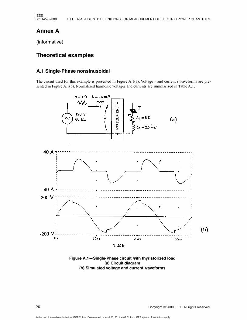
A.1 Single-Phase nonsinusoidal
The circuit used for this example is presented in Figure A.1(a). Voltage v and current i waveforms are pre-sented in Figure A.1(b). Normalized harmonic voltages and currents are summarized in Table A.1.
Figure A.1—Single-Phase circuit with thyristorized load(a) Circuit diagram
(b) Simulated voltage and current waveforms
Authorized licensed use limited to: IEEE Xplore. Downloaded on April 20, 2011 at 03:01 from IEEE Xplore. Restrictions apply.

IEEEUNDER SINUSOIDAL, NONSINUSOIDAL, BALANCED, OR UNBALANCED CONDITIONS Std 1459-2000
Copyright © 2000 IEEE. All rights reserved. 29
The values of the rms, fundamental, and total harmonic voltage and current are as follows:
The total harmonic distortions of voltage and current are as follows:
Computations lead to the results summarized in Table A.2.
Table A.1—Percent Harmonic Voltage and Current Phasors. Base Values: V1 = 111.09 V; I1 = 11.17 A
h 1 3 5 7 9 11 13 15
Vh (%) 100.00 5.98 1.74 2.00 1.15 1.14 0.85 0.89
αh (deg) 23.80 –39.12 173.3 21.39 –120.10 87.24 –60.68 156.40
Ih (%) 100.00 51.20 12.78 12.47 5.38 5.51 3.10 3.04
βh (deg) –23.31 115.70 –43.38 161.30 16.11 –141.80 82.66 –79.19
Table A.2—Percent powersBase value: S1 = 1229.70 VA
Se = 114.41 S1 = 100.00 SN = 55.59SH = 3.80
P = 66.35 P1 = 69.61 PH = –3.26
N = 93.20 Q1 = 73.07 DI = 55.06DV = 6.91DH = 1.96
QB = 71.58 DB = 59.69
V 110.35 V=
V 1 110.09 V=
V H 7.55 V=
I 12.75 A=
I1 11.17 A=
IH 6.15 A=
THDV 0.069=
THDI 0.549=
PF P S⁄ 0.580= = PF1 P1 S1⁄ 0.696= = SN S1⁄ 0.556=
Authorized licensed use limited to: IEEE Xplore. Downloaded on April 20, 2011 at 03:01 from IEEE Xplore. Restrictions apply.
IEEEStd 1459-2000 IEEE TRIAL-USE STD DEFINITIONS FOR MEASUREMENT OF ELECTRIC POWER QUANTITIES
30
Copyright © 2000 IEEE. All rights reserved.
The nonlinear load is supplied with a 60 Hz active power , and oper-ates with a power factor
P
F
= 0.580 and a fundamental factor . A small part of the60 Hz active power is converted by the triac into harmonic power (returned to the power system) as follows:
The fundamental current lags the fundamental voltage by an angle , yield-ing a 60 Hz reactive power as follows:
Budeanu’s reactive power , is smaller than
Q
1
.
The degree of distortion can be estimated with the ratio , which is nearly equal to.
The overall amount of
harmonic pollution
is quantified with the help of the non-60 Hz apparent power asfollows:
This value is nearly equal to the current distortion power . The small difference is due tothe voltage distortion power and the harmonic apparent power .
The fundamental apparent power
S
1
and its components
P
1
and
Q
1
make up the bulk of the apparent power S . Nevertheless, in this particular example, the nonfundamental apparent power S N represents a significant
amount of the total apparent power.
A.2 Three-Phase balanced nonsinusoidal system
The circuit is shown in Figure A.2. In this example, the third and the ninth harmonic currents are zero-sequence components and cause a large neutral current, which results in additional energy loss in the neutralconductor. Harmonic phasors obtained from this circuit simulation are summarized in Table A.3. Voltage andcurrent components of higher interest have the following rms and total harmonic distortion values:
; ; ;
; ; ;
; ; ;
; ;
The neutral current has no 60 Hz, 300 Hz, or 420 Hz components (i.e., neither positive nor negativesequence components). The line-to-line voltage, however, lacks the 180 Hz and the 540 Hz components(zero-sequence). This situation is reflected in the following apparent power computations:
A 0.94% difference between these two values is observed.
P1 0.6961 1229.7× 856.04 W= =PF1 θ1cos 0.696= =
PH 0.0326 1229.70×– 40.1 W–= =
θ1 23.80° 23.31°+ 47.11°= =
Q1 0.7307 1229.7× 898.61 var= =
QB 880.22 var=
SN S1⁄ 0.556=THDI 0.549=
SN 0.556 1229.70× 683.63 VA= =
D1 677.05 var=DV 84.97 var= SH 46.73 VA=
V a 279.94 V= V a1 277.25 V= V aH 38.70 V= THDVa 0.139=
V ab 480.29 V= V ab1 480.20 V= V abH 9.55 V= THDVab 0.020=
Ia 129.40 A= Ia1 99.58 A= IaH 82.25 A= THDIa 0.823=
In 207.20 A= In1 0 A= InH 207.20 A=
3V lnIa 3 279.94 129.4×× 108.673 kVA= =
3V llIa 3 480.29 129.4×× 107.646 kVA= =
Authorized licensed use limited to: IEEE Xplore. Downloaded on April 20, 2011 at 03:01 from IEEE Xplore. Restrictions apply.

IEEEUNDER SINUSOIDAL, NONSINUSOIDAL, BALANCED, OR UNBALANCED CONDITIONS Std 1459-2000
Copyright © 2000 IEEE. All rights reserved.
31
Figure A.2—Three-Phase, four-wire circuit with a nonlinear balanced load (a) Circuit diagram
(b) Simulated voltage and current waveforms
Authorized licensed use limited to: IEEE Xplore. Downloaded on April 20, 2011 at 03:01 from IEEE Xplore. Restrictions apply.
IEEEStd 1459-2000 IEEE TRIAL-USE STD DEFINITIONS FOR MEASUREMENT OF ELECTRIC POWER QUANTITIES
32
Copyright © 2000 IEEE. All rights reserved.
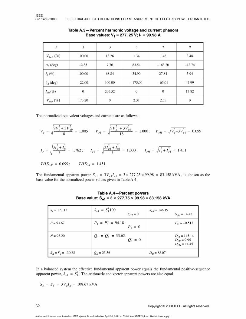
The normalized equivalent voltages and currents are as follows:
; ;
; ;
;
The fundamental apparent power , is chosen as thebase value for the normalized power values given in Table A.4.
In a balanced system the effective fundamental apparent power equals the fundamental positive-sequenceapparent power, . The arithmetic and vector apparent powers are also equal.
Table A.3—Percent harmonic voltage and current phasorsBase values:
V
1
= 277. 25 V;
I
1
= 99.98 A
h
1 3 5 7 9
100.00 13.26 1.34 1.48 3.48
α
h
(deg)
–2.35 7.76 83.54 –163.20 –42.74
I
h
(%) 100.00 68.84 34.90 27.84 5.94
β
h
(deg) –22.00 100.00 –175.00 –65.01 47.99
I
nh
(%) 0 206.52 0 0 17.82
173.20 0 2.31 2.55 0
Table A.4—Percent powersBase value:
S
e1
= 3
×
277.75
×
99.98 = 83.158 kVA
S
e
= 177.13
S
U1
= 0
S
eN
= 146.19
S
eH
= 14.45
P
= 93.67
P
H
= –0.513
N
= 93.20
D
eI
= 145.14
D
eV
= 9.95
D
eH
= 14.45
S
A
=
S
V
= 130.68
Q
B
= 23.36
D
B
= 88.07
V lnh (%)
V llh (%)
V e
9V a2 3V ab
2+
18---------------------------- 1.005= = V e1
9V a12 3V ab1
2+
18--------------------------------- 1.000= = V eH V e
2 3– V e12 0.099= =
Ie
3Ia2 In
2+
3------------------- 1.762= = Ie1
3Ia12 In1
2+
3----------------------- 1.000= = IeH Ie
2 Ie12+ 1.451= =
THDeV 0.099= THDeI 1.451=
Se1 3V e1Ie1 3 277.25 99.98×× 83.158 kVA= = =
Se1 S1+100=
P1 P1+ 94.18= =
P1– 0=
Q1 Q1+ 33.62= =
Q1– 0=
Se1 S1+=
SA SV 3V aIa 108.67 kVA= = =
Authorized licensed use limited to: IEEE Xplore. Downloaded on April 20, 2011 at 03:01 from IEEE Xplore. Restrictions apply.

IEEEUNDER SINUSOIDAL, NONSINUSOIDAL, BALANCED, OR UNBALANCED CONDITIONS Std 1459-2000
Copyright © 2000 IEEE. All rights reserved.
33
The normalized values are . The normalized active power is with a nor-malized fundamental active power . These active and apparent powers give the followingpower factors:
Significant differences are apparent among these three power factor values. The effective apparent poweryields the lowest power factor. This is due to the fact that . The equivalent current
I
e
covers the ther-mal effect of the neutral current
I
n
, hence . The definition of
I
e
is based on the equivalence of the totalline power loss, neutral current included.
The same result is obtained by using the following expression:
i.e., 1055 W is due to the line currents and 901 W is due to the neutral current.
The vector apparent power
S
V
definition ignores the fact that, in spite of the balanced load and symmetricalvoltages, there is a substantial neutral current. This becomes evident when comparing the followingexpression:
with
The harmonic active power is not a good indicator of the harmonic pollution magnitude.Its value depends not only on the
I
eH
or
S
eN
, but also on the system’s Thevenin impedance. A larger
r
willincrease
P
H
, while
S
eN
will remain practically unchanged. The correct way to evaluate harmonic pollution iswith .
A.3 Three-Phase unbalanced nonsinusoidal system
The previous example was modified by disconnecting phase c, Figure A.3. A capacitor wasconnected between terminals b and n to enhance the difference between the current spectra of i
a and i
b .
SA SV 130.68%= = P 93.67%=P1 94.18%=
PFePSe----- 0.529= =
PFA PFVPSA------ 0.717= = =
PF1+ θ1
+cosP1
+
S1+
------ 0.942= = =
Se SA>Ie Ia>
∆Pe 3rIe2 3 0.021 1.762 99.98×( )2×× 1956 W= = =
∆Pe 3rIa2 rnIn
2+ 3 0.021 129.42 0.021 207.22×+×× 1055 901+ 1956 W= = = =
∆PV rSV
2
V ab2
-------- 0.021107646480.29------------------
2
1055 W= = =
∆Pe rSe
2
3V e2
--------- 0.021147298
3 278.62×------------------------------
21956 W= = =
PH 0.513%–=
SeN Se1 THDeI( )≈
C 338 µ F =
Authorized licensed use limited to: IEEE Xplore. Downloaded on April 20, 2011 at 03:01 from IEEE Xplore. Restrictions apply.

IEEEStd 1459-2000 IEEE TRIAL-USE STD DEFINITIONS FOR MEASUREMENT OF ELECTRIC POWER QUANTITIES
34
Copyright © 2000 IEEE. All rights reserved.
Figure A.3—Three-Phase, four-wire circuit with a nonlinear unbalanced load(a) Circuit diagram
(b) Simulated voltage and current waveforms
Authorized licensed use limited to: IEEE Xplore. Downloaded on April 20, 2011 at 03:01 from IEEE Xplore. Restrictions apply.

IEEEUNDER SINUSOIDAL, NONSINUSOIDAL, BALANCED, OR UNBALANCED CONDITIONS Std 1459-2000
Copyright © 2000 IEEE. All rights reserved.
35
The percent harmonic voltage and current phasors are given in Table A.5.
Some of the important computed quantities are as follows:
; ;
; ; ;
; ; ;
; ; ;
; ; ;
; ; ;
Table A.5—Percent harmonic voltage and current phasorsBase values:
V
a1
= 271.03 V;
I
a1
= 99.98 A
h
1 3 5 7 9
V
ah
(%) 100.00 10.28 4.92 7.44 8.64
α
ah
(deg) –0.74 6.76 142.30 146.70 –47.40
I
ah
(%) 100.00 68.84 34.90 27.85 5.93
β
ah
(deg) –22.00 100.00 –175.00 –65.00 48.00
V
bh
(%) 104.49 10.53 5.79 8.58 11.05
α
bh
(deg) –121.20 6.28 167.40 125.20 –49.19
I
bh
(%) 93.49 79.77 42.30 45.81 40.59
β
bh
(deg) –120.80 99.49 65.09 –167.90 41.89
V
ch
(%) 103.73 8.69 4.30 6.58 8.22
α
ch
(deg) 121.30 9.70 157.70 136.50 –47.35
Ich (%) 0 0 0 0 0
Inh (%) 178.12 21.01 63.28 67.87 65.75
Vabh (%) 177.56 0.26 2.48 3.19 2.43
Vbch (%) 177.93 1.93 1.65 2.49 2.84
Vcah (%) 178.28 1.67 1.36 1.51 0.41
V a 274.53 V= V a1 271.03 V= V aH 43.70 V= THDVa 0.161=
V b 287.57 V= V b1 283.20 V= V bH 49.94 V= THDVb 0.176=
V c 283.81 V= V c1 281.13 V= V cH 38.85 V= THDVc 0.138=
V ab 481.43 V= V ab1 481.26 V= V abH 12.79 V= THDVab 0.027=
V bc 482.41 V= V bc1 482.25 V= V bcH 12.34 V= THDVbc 0.026=
V ca 483.22 V= V ca1 483.17 V= V caH 7.22 V= THDVca 0.015=
Authorized licensed use limited to: IEEE Xplore. Downloaded on April 20, 2011 at 03:01 from IEEE Xplore. Restrictions apply.

IEEEStd 1459-2000 IEEE TRIAL-USE STD DEFINITIONS FOR MEASUREMENT OF ELECTRIC POWER QUANTITIES
36
Copyright © 2000 IEEE. All rights reserved.
; ; ;
; ; ;
; ; ;
; ; ;
The equivalent voltages and currents are as follows:
The following are several key values of computed phasors:
; ;
; ;
; ;
; ;
Ia 129.40 A= Ia1 99.98 A= IaH 82.25 A= THDIa 0.823=
Ib 143.64 A= Ib1 93.48 A= IbH 109.07 A= THDIb 1.167=
Ic 0 A= Ic1 0 A= IcH 0 A=
In 210.66 A= In1 125.93 A= InH 168.90 A= THDIn 1.341=
V e
3 V a2 V b
2 V c2+ +( ) V ab
2 V bc2 V ca
2+ + +
18------------------------------------------------------------------------------------- 280.25 V= =
V e1
3 V a12 V b1
2 V c12+ +( ) V ab1
2 V bc12 V ca1
2+ + +
18---------------------------------------------------------------------------------------------------- 278.45 V= =
V eH V e2 V e1
2+ 31.68 V= =
THDVe 0.114=
Ie
Ia2 Ib
2 Ic2 In
2+ + +
3------------------------------------- 165.08 A= =
Ie1
Ia12 Ib1
2 Ic12 In1
2+ + +
3----------------------------------------------- 107.38 A= =
IeH Ie2 Ie1
2+ 125.41 A= =
THDIe 1.168=
V a1 271.03 0.74° V– ∠ = V b1 283.2 121.2° V– ∠ = V c1 281.13 121.3° V– ∠ =
V 1+ 288.49 0.20° V– ∠ = V 1
– 0.63 83.36° V– ∠ = V 10 2.98 143.04° V– ∠ =
Ia1 99.98 22° A– ∠ = Ib1 93.48 120.8° A– ∠ = Ic1 0 A=
I1+ 63.39 11.76° A– ∠ = I1
– 21.52 43.15° A– ∠ = I10 42.00 69.15° A– ∠ =
Authorized licensed use limited to: IEEE Xplore. Downloaded on April 20, 2011 at 03:01 from IEEE Xplore. Restrictions apply.

IEEEUNDER SINUSOIDAL, NONSINUSOIDAL, BALANCED, OR UNBALANCED CONDITIONS Std 1459-2000
Copyright © 2000 IEEE. All rights reserved.
37
Powers normalized to are summarized in Table A.6.
The arithmetic apparent power is as follows:
The vector apparent power is as follows:
The effective apparent power is as follows:
The total active power is as follows:
The power factors are as follows:
Table A.6—Percent powers Base value:
S
e1
= 3
×
278
×
107.38 = 89.70 kVA
S
e
= 154.73
S
e1
= 100.00
S
U1
= 78.88
S
eN
= 118.08
S
eH
= 13.29
P
= 57.23
P
1
= 57.67
P
H
= –0.44
N
= 143.76
D
eI
= 116.77
D
eV
= 11.38
D
eH
= 13.28
S
V
= 84.62
Q
B
= 2.62
D
B
= 62.28
S
A
= 85.65
Se1 3 278 107.38×× 89.70 kVA= =
SA Sa Sb Sc+ + 35.524 41.306 0+ + 76.83 kVA= = =
SV P2 QB2 DB
2+ + 51.3332 2.3492 55.8712+ + 75.91 kVA= = =
Se 3V eIe 3 280.25 165.08×× 138.79 kVA= = =
P Pa Pb Pc+ + 24.998 26.335 0+ + 51.33 kW= = =
PFA51.3376.83------------- 0.668= =
PFV51.3375.91------------- 0.676= =
PFe51.33138.79---------------- 0.370= =
S1+ 59.04=
P1+ 57.84=
P1– 0.03–=
P10 0.14–=
Q1+ 11.83=
Q1– 0.03–=
Q10 0.40–=
Authorized licensed use limited to: IEEE Xplore. Downloaded on April 20, 2011 at 03:01 from IEEE Xplore. Restrictions apply.

IEEEStd 1459-2000 IEEE TRIAL-USE STD DEFINITIONS FOR MEASUREMENT OF ELECTRIC POWER QUANTITIES
38
Copyright © 2000 IEEE. All rights reserved.
The 60 Hz positive-sequence powers give the following:
The large differences between the power factor values are due to large differences among apparent powersvalues.
As in the previous example the total line losses are as follows:
The neutral conductor power loss, included in , is as follows:
The total harmonic distortion of the equivalent current is as follows:
and due to the neutral current contribution exceeds phase current distortions.
The ratio
D
eI
/S
e1
= 1.117 indicates a significant nonsinusoidal situation that is quantified by
S
eN
= 100.29 kVA.
This example demonstrates that large differences can occur between
Q
B
and ; 2.62% versus 11.83%.This issue is further emphasized in Annex B, which presents actual field studies.
PF1+ θ1
+cosP1
+
S1+
------ 51.8852.96------------- 0.980= = = =
∆Pe 3rIe2 3 0.021 165.082×× 1717.8 W= = =
∆Pe
∆Pn rIn2 0.021 210.662× 931.9 W= = =
THDIe
IeH
Ie1-------- 1.168= =
Q1+
Authorized licensed use limited to: IEEE Xplore. Downloaded on April 20, 2011 at 03:01 from IEEE Xplore. Restrictions apply.

IEEEUNDER SINUSOIDAL, NONSINUSOIDAL, BALANCED, OR UNBALANCED CONDITIONS Std 1459-2000
Copyright © 2000 IEEE. All rights reserved.
39
Annex B
(informative)
Practical studies and measurements
B.1 Power survey at a large industrial plant
5
In 1997, a team of South African engineers (Pretorius, van Wyk, and Swart [B11]) studied and compared afew methods of power resolutions for accuracy, usefulness, and suitability for revenue purpose. The follow-ing conclusions were reached by the surveying team:
a) Budeanu’s method gives erroneous results. b) The IEEE Working Group method (presented in this Trial-Use standard), based on the Buchholz-
Goodhue definition of effective apparent power S e and its resolution in S
e1 and S
eN “is encouraged
because it is merely an extension of the classical sinusoidal definitions that are already wellunderstood.”
c) The IEEE Working Group method “accurately describes the rating of power compensation equip-ment, that ought to be used in practice and is a good resolution method to indicate the severity ofdistortion in practical power systems.”
d) Other methods studied did yield “mathematically correct results, but are difficult to apply in practicedue to measurement problems,” the stumbling block being the need for precise measurement of theactive power per each harmonic order.
The diagram of the studied system is shown in Figure B.1. This facility is supplied with three-phase, 50 Hz,11 kV/380 V, from two separate 2MVA, 5.69%, transformers. The major loads consist of 13 pulsedpower supplies, ac/dc converters (regulating pulse units) with the following nominal values:
380 V78.7 A60.35 kVA
This location was selected for its ideal conditions, created by the fact that several passive and active filterswere already installed and permission was obtained to connect and disconnect the filters. Some of the resultspublished in Pretorius, van Wyk, and Swart [B11] are listed and discussed in the following:
1. MEASUREMENTS AT THE PRIMARY SIDE OF TRANSFORMER 1
All the filters were disconnected. Voltage and current waveforms and spectra are presented in Figure B.2.
The most important quantities measured are as follows:
; ; ;
; ; ; ;
;
5
This information is provided with permission from
Pretorius, van Wyk, and Swart
[B11].
∆ Y⁄
THDI 38%≈
V ln 6445.1 V= I l 51.36 A= THDV 0.0016= THDI 0.718=
P 653.78 kW= P5 90.7 W–= P7 50 W–= P11 11.3 W–= P13 1.7 W–=
PF1 0.811= PF 0.658=
Authorized licensed use limited to: IEEE Xplore. Downloaded on April 20, 2011 at 03:01 from IEEE Xplore. Restrictions apply.

IEEEStd 1459-2000 IEEE TRIAL-USE STD DEFINITIONS FOR MEASUREMENT OF ELECTRIC POWER QUANTITIES
40
Copyright © 2000 IEEE. All rights reserved.
Figure B.1—Schematic of the surveyed industrial plant
Authorized licensed use limited to: IEEE Xplore. Downloaded on April 20, 2011 at 03:01 from IEEE Xplore. Restrictions apply.

IEEEUNDER SINUSOIDAL, NONSINUSOIDAL, BALANCED, OR UNBALANCED CONDITIONS Std 1459-2000
Copyright © 2000 IEEE. All rights reserved.
41
Values of the measured powers are given in Table B.1.
Table B.1—Powers measured at the primary side of transformer 1
S
= 993.08 kVA
S
1
= 806.52 kVA
S
U1
= 0.33 kVA
S
N
= 579.42 kVA
S
H
= 0.96 kVA
P
= 653.78 kW
P
1
= 653.93 kW
P
H
= –157 W
Q
1
= 472.07 kvar
D
I
= 579.40 kvar
D
V
= 1.33 kvar
D
H
= 0.94 kvar
Q
B
= 471.16 kvar
D
B
= 580.35 kvar
Figure B.2—Measurements at the primary side of Transformer 1(a) Line-to-Line voltage and line current
(b) Normalized harmonic spectrum(c) Normalized current spectrum
Authorized licensed use limited to: IEEE Xplore. Downloaded on April 20, 2011 at 03:01 from IEEE Xplore. Restrictions apply.
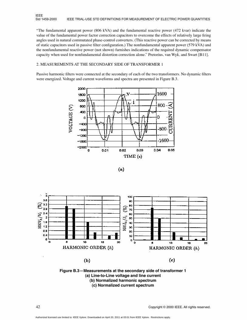
IEEEStd 1459-2000 IEEE TRIAL-USE STD DEFINITIONS FOR MEASUREMENT OF ELECTRIC POWER QUANTITIES
42
Copyright © 2000 IEEE. All rights reserved.
“The fundamental apparent power (806 kVA) and the fundamental reactive power (472 kvar) indicate thevalue of the fundamental power factor correction capacitors to overcome the effects of relatively large firingangles used in natural commutated phase-control converters. (This reactive power can be corrected by meansof static capacitors used in passive filter configuration.) The nonfundamental apparent power (579 kVA) andthe nonfundamental reactive power (not shown) furnishes indications of the required dynamic compensatorcapacity when used for nonfundamental distortion correction alone.” Pretorius, van Wyk, and Swart [B11].
2. MEASUREMENTS AT THE SECONDARY SIDE OF TRANSFORMER 1
Passive harmonic filters were connected at the secondary of each of the two transformers. No dynamic filterswere energized. Voltage and current waveforms and spectra are presented in Figure B.3.
Figure B.3—Measurements at the secondary side of transformer 1(a) Line-to-Line voltage and line current
(b) Normalized harmonic spectrum(c) Normalized current spectrum
Authorized licensed use limited to: IEEE Xplore. Downloaded on April 20, 2011 at 03:01 from IEEE Xplore. Restrictions apply.

IEEEUNDER SINUSOIDAL, NONSINUSOIDAL, BALANCED, OR UNBALANCED CONDITIONS Std 1459-2000
Copyright © 2000 IEEE. All rights reserved. 43
The most important quantities measured are as follows:
; I = 616.6 A THDV = 0.046; THDI = 0.913
P = 331.29 kW; P5 = –105.5 W; P7 = –47.6 W; P11 = –6.3 W; P13 = –0.7 W
PF1 = 1.000; PF = 0.737
Values of the measured powers are given in Table B.2.
The existence of filters causes phase shifting of harmonic phasors that produce QB = –12.47 kvar < 0. Com-paring Q1 = 0.94 kvar with QB = –12.47 kvar, it becomes obvious that Budeanu’s Resolution “cannot beused to design or to specify ratings of equipment in any situation and its use in industry must be abandonedin total.”
Table B.2— Powers measured at the secondary side of Transformer 1
S = 449.25 kVA S1 = 331.46 kVASU1 = 0.37 kVA
SN = 303.25 kVASH = 13.91 kVA
P = 331.29 kW P1 = 331.46 kW PH = –163 W
— Q1 = 0.94 kvar DI = 302.53 kvarDV = 15.24 kvarDH = 13.91 kvar
— QB = –12.47 kvar DB = 303.17 kvar
V ln 242.9 V=
Authorized licensed use limited to: IEEE Xplore. Downloaded on April 20, 2011 at 03:01 from IEEE Xplore. Restrictions apply.
IEEEStd 1459-2000
44
Copyright © 2000 IEEE. All rights reserved.
Annex C
(informative)
Bibliography
[B1] Buchholz, F., “Die Drehstrom-Scheinleistung bei Ungleichmassiger Belastung Der Drei Zweige,”
Lichtund Kraft,
No.2, Jan. 20, 1922, pp. 9–11.
[B2] Czarnecki, L. S., “What is Wrong with Budeanu’s Concept of Reactive and Distortion Power andWhy it Should be Abandoned,”
IEEE Transactions on Instrumentation and Measurement,
Vol. IM-36, No.3,Sept. 1987.
[B3] Depenbrock, M., and Staudt, V., Discussion to [B9].
[B4] Emanuel, A. E., “Apparent Power Definitions for Three-Phase Systems,”
IEEE Transactions on PowerDelivery,
Vol. 14, No. 3, July 1999, pp. 767–72.
[B5] Emanuel, A. E., “On the Assessment of Harmonic Pollution,”
IEEE Transactions on Power Delivery,
Vol. 10, No. 3, July 1995, pp.1693–98.
[B6] Filipski, P. S., Baghzouz, Y., and Cox, M. D., “Discussion of Power Definitions Contained in the IEEEDictionary,”
IEEE Transactions on Power Delivery,
Vol. 9, No. 3, July 1994, pp. 1237–44.
[B7] Goodhue, W. M., Discussion to “Reactive Power Concepts in Need of Clarification,”
AIEE Transac-tions,
Vol. 52, Sept. 1933, p. 787.
[B8] IEEE 100-1996,
The IEEE Standard Dictionary of Electrical and Electronics Terms,
Sixth Edition.
[B9] IEEE Working Group on Nonsinusoidal Situations, “Practical Definitions for Powers in Systems withNonsinusoidal Waveforms and Unbalanced Loads,”
IEEE Transactions on Power Delivery,
Vol. 11, No. 1,Jan. 1996, pp.79–101.
[B10] Lyon, V., [Discussion to H. L. Curtis and F. B. Silsbee paper “Definitions of Power and Related Quan-tities,” AIEE Transactions, Vol. 54, No. 4, April 1935, pp. 394–404],
Electrical Engineering,
Oct. 1935,p. 1121.
[B11] Pretorius, J. H. C., van Wyk, J .D., and Swart, P. H., “An Evaluation of some Alternative Methods ofPower Resolutions in a Large Industrial Plant,”
Proceedings of the Eighths International Conference onHarmonics and Quality of Power (ICHQP- VIII),
Athens, Vol. I, Oct. 1998, pp. 331–6.
[B12] Stevens, R. H., “Power Flow Direction Definitions for Metering of Bidirectional Power,”
IEEE Trans-actions on Power Apparatus and Systems,
Vol. 102, No. 9, Sept. 1983, pp. 3018–21.
[B13] Swart, P. H., van Wyk, J. D., and Case, M. J., “On the Technique for Localization of SourcesProducing Distortion in Transmission Networks,”
European Transactions on Electrical Powers (ETEP),
Vol. 6, No. 5, Sept./Oct. 1996.
Authorized licensed use limited to: IEEE Xplore. Downloaded on April 20, 2011 at 03:01 from IEEE Xplore. Restrictions apply.