ieeetransactions on wireless communications 1 …wides.usc.edu/assets/002/91123.pdf ·...
TRANSCRIPT

IEEE TRANSACTIONS ON WIRELESS COMMUNICATIONS 1
Coherent UWB Ranging in the Presence ofMultiuser Interference
Vinod Kristem, Andreas F. Molisch, Fellow, IEEE, S. Niranjayan, Member, IEEE, andSeun Sangodoyin, Student Member, IEEE
Abstract—Roundtrip time-of-arrival (ToA) measurements em-ploying ultra-wideband (UWB) signals can provide high-precision ranging information. However, the accuracy is degradedby multiuser interference (MUI), in particular in the presence ofmultipath propagation. While the processing gain of time-hoppingimpulse radio (TH-IR) can be used to suppress the MUI, thisis often insufficient. We propose instead a nonlinear processingscheme of TH-IR that effectively suppresses MUI without requir-ing knowledge of the time-hopping sequences of the interferingusers. The principle is that multipath components (MPCs) of inter-ferers do not align closely, for the majority of transmission frames,with the MPCs of the desired signal. Through a judicious choiceof algorithm parameters we show that our algorithm is superiorto existing (realizable) thresholding and median filter algorithms,and in some cases can even beat genie-aided thresholding algo-rithms. The performance is robust to both strength and number ofthe interferers. The results are validated with both standardized802.15.4a channel models and measured outdoor UWB channels.
Index Terms—Ranging, time-of-arrival (ToA), multiuser inter-ference, ultra-wideband (UWB).
I. INTRODUCTION
ACCURATE position information is of high importancein many commercial, public safety, and military appli-
cations. While Global Positioning System (GPS) serves thispurpose in outdoor environments, it is often unreliable orinaccessible in cluttered environments such as indoors, nar-row street canyons, caves, and dense forests. For this reason,alternative positioning techniques based on ranging betweenground-based devices need to be explored. While fingerprintingof received signal strength (RSS) has received great attention[3], [4], the ranging accuracy depends on access to a databaseof RSS. Ranging using the ultra-wideband (UWB) signals ispromising due to the good range resolution associated withlarge bandwidth.
Ranging techniques are based on time-of-arrival (ToA) of thefirst path. ToA estimation is mainly affected by receiver noise,multipath propagation and interference. In a dense multipath
Manuscript received September 19, 2013; revised January 30, 2014; ac-cepted March 30, 2014. This work was supported in part by the Office ofNaval Research (ONR), Defense University Research Instrumentation Program(DURIP), and Major Research Instrumentation (MRI). This work will appearin part in Int. Conf. on Communication (ICC), 2014. The associate editorcoordinating the review of this paper and approving it for publication wasY. Sanada.
The authors are with the Department of Electrical Engineering, Universityof Southern California, Los Angeles, CA 90089-2560 USA (e-mail: [email protected]; [email protected]; [email protected]; [email protected]).
Color versions of one or more of the figures in this paper are available onlineat http://ieeexplore.ieee.org.
Digital Object Identifier 10.1109/TWC.2014.2317741
channel, the first path is not always the strongest path therebymaking ToA estimation challenging.
UWB ranging in the presence of noise and multipath prop-agation has been studied extensively in the literature. For asingle path additive white Gaussian noise (AWGN) channels,a matched-filtering (MF) receiver is the maximum likelihood(ML) ToA estimator with theoretical bounds on the rangingerror given in [11]–[13]. For AWGN with multipath, [14] and[15], respectively derived the Cramer-Rao bound (CRB) andZiv-Zakai bound (ZZB) on the mean square error (MSE) in ToAestimation. The ML estimators for the ToA estimation wereproposed in [16] and [17]; however, computational complexityof these estimators limits their implementation. Practical sub-optimal ToA estimators were proposed in [18], [19]. Severallow complexity, subsampling ToA estimators, based on energy-detection (ED) have been proposed in [19]–[21]. The perfor-mance of MF and ED receivers has been summarized in [22].A two-step hybrid ToA estimator was proposed in [23]. In it,the coarse estimate is obtained from energy detection and afine estimate is obtained from matched-filtering. A blind—ToAestimator based on model selection by information theoreticcriteria is proposed in [24].
Very few papers in the literature addressed the issue ofinterference in UWB ranging. In multiuser network, signalsfrom multiple users can interfere with the desired signal therebydeteriorating the ranging accuracy. While using distinct time-hopping (TH) sequences for different users, followed by co-herent combining of signals, can suppress the interference toa certain extent, the residual interference can be significantcompared to the first arriving path from the desired user, andhence can result in early false alarms. This is because the firstarriving path is not always the strongest path. In fact, it can havesignificantly lower energy than the strongest path, especiallyin non-line of sight (NLOS) conditions. Thus this effect mightoccur even in the absence of near/far effects that are the reasonfor significant MUI in TH communication systems. Hence,finding a good threshold to separate the interference multipathcomponents (MPC) from the first MPC of the desired user isdifficult or even impossible.
Ref. [25] proposed non-linear filtering schemes like mini-mum filtering and median filtering to mitigate the multiuserinterference (MUI). Ref. [26] considered both MUI and nar-rowband interference (NBI), and proposed differential filtering,to mitigate the interference. These papers considered the EDreceivers and studied the performance with only one interfer-ing user. While the ED receivers have low cost implementa-tion, their performance is poor compared to matched-filtering
1536-1276 © 2014 IEEE. Personal use is permitted, but republication/redistribution requires IEEE permission.See http://www.ieee.org/publications_standards/publications/rights/index.html for more information.

2 IEEE TRANSACTIONS ON WIRELESS COMMUNICATIONS
(coherent) receivers, especially when the signal-to-noise ratio(SNR) is small. Also, the energy based non-linear filteringschemes cannot exploit noise averaging across frames, as thenoise becomes correlated after filtering. MUI mitigation inUWB ranging using coherent receivers is considered in [27].However, it was assumed that the receiver knows the THsequences of all the interfering users, and proposed an iterativesuccessive interference cancellation technique for ToA esti-mation. In a dense multipath channel, this approach becomescomputationally intense. More importantly, acquiring the THsequences of all the interfering users is difficult especially whenthe users are mobile. It can also happen that the interfering usersare hostile and do not share their TH sequences.
The key contributions of the paper are
• A novel coherent ranging algorithm that suppresses theMUI without having to know the TH sequences of theinterfering users. Only the TH sequence of the desired useris known to the receiver. To the best of our knowledge, thisis the first paper in the literature that talks about the MUIsuppression for coherent UWB ranging, without having toknow the TH sequences of the interfering users. We makeuse of the fact that after de-hopping the received signal,the receiver effectively has multiple waveforms, one perevery frame duration in the TH signal. While the signalMPCs in these waveforms are time-aligned, because ofthe time-hopping nature, an interference MPC hops aroundthe signal MPCs across different waveforms, thereby mak-ing it feasible to separate an interference MPC from asignal MPC.
• Performance bounds: We model the MPC delays by aPoisson process and develop bounds on the false alarmprobability from interference and noise MPCs and detec-tion probability of signal MPCs, as a function of algorithmparameters.
• We provide a judicious choice of parameters and usingthe analytical expressions derived earlier, we show thatthe proposed algorithm effectively suppresses the stronglyinterfering MPCs.
• Performance evaluation with synthetic channels: UsingIEEE 802.15.4a channel models, we show that the pro-posed ranging scheme is robust to the strength of inter-ference and the number of interfering users in the system,and performs much better than the thresholding schemesand the non-linear filtering schemes considered in theliterature.
• Experimental study of performance: We also carried outan urban outdoor channel measurement campaign with aUWB channel sounder and tested the performance of ouralgorithm in both LOS and NLOS measured scenarios.We compare the performance of our ranging scheme withsome well-known coherent and non-coherent thresholdingschemes.
The paper is organized as follows. The system model isdeveloped in Section II. The thresholding schemes and the pro-posed ranging algorithm are described in Section III-A and B,respectively. The performance bounds for the proposed rangingscheme are developed in Section IV. The performance evalu-
ation is done with synthetic channels in Section V. The mea-surement description and the corresponding results are given inSection VI. Finally, the paper is concluded in Section VII. Themathematical details are moved to the Appendix.
II. SYSTEM MODEL
We consider a multiuser network with (I + 1) users si-multaneously transmitting at any given time. Without loss ofgenerality, we assume the first user as desired and the other Iusers as interference. The users are assigned fixed and distinctTH sequences. The TH signal transmitted by the ith user isgiven by [6]
si(t)=√Ei
N∑n=1
p (t−(n−1)Tf−ci(n)Tc−Di) , 0≤ t≤NTf
where p(t) is the unit energy UWB pulse, Ei is the signalenergy per frame, and ci is the chip sequence of the ith userwith ci ∈ {0, 1, . . . , Nc − 1}Nc . Tc is the chip duration, Tf isthe frame duration, Nc is the size of the code alphabet and thenumber of chips per frame (Tf = NcTc), and N is the numberof frames per symbol. Di is the transmission start time of the ithuser. Without loss of generality, we assume D1 = 0. We assumethat all users use the same pulse shape p(t).
Let hi(t) denote the impulse response of the channel betweenthe ith user and the receiver. The received signal is given by1
r(t) =
I+1∑i=1
si(t) ∗ hi(t) + n(t) (1)
where (∗) is the convolution operation and n(t) is the zero-mean AWGN with variance N0. The model implicitly assumesthat the channel is quasi-static during the transmission ofthe ranging signals; given typical pedestrian coherence times(∼10 ms [1]), this is a realistic assumption. We assume thatNBI can be removed by notch filtering and hence do notmodel it.
The signal-to-noise ratio (SNR) and signal-to-interferenceratio (SIR) for the desired user are defined as follows:
SNRΔ=
E1
N0, SIR(i)
Δ=
E1
Ei+1, i = 1, 2, . . . , I. (2)
Notice that SIR in general is a function of the user index asdifferent interfering users can transmit with different powerand can be at different distances from the receiver. We assumethat the receiver only knows the TH sequence of the desireduser and not of the interfering users. The receiver can nowperform the de-hopping process, by dividing the observation
time into N intervals, InΔ= [c1(n)Tc + (n− 1)Tf , c1(n)Tc +
(n− 1)Tf + T ], 1 ≤ n ≤ N , each of length T (T < Tf ). Weassume that the delay spread of the channel is smaller than oneframe duration. Without loss of generality, we assume that thechip-sequence for the desired user is the all zero sequence.
1The frames from different users can arrive at different times, which isimplicitly captured by the channel impulse response of the users. The delaycorresponding to the first MPC can be different for different users.
KRISTEM et al.: COHERENT UWB RANGING IN THE PRESENCE OF MULTIUSER INTERFERENCE 3
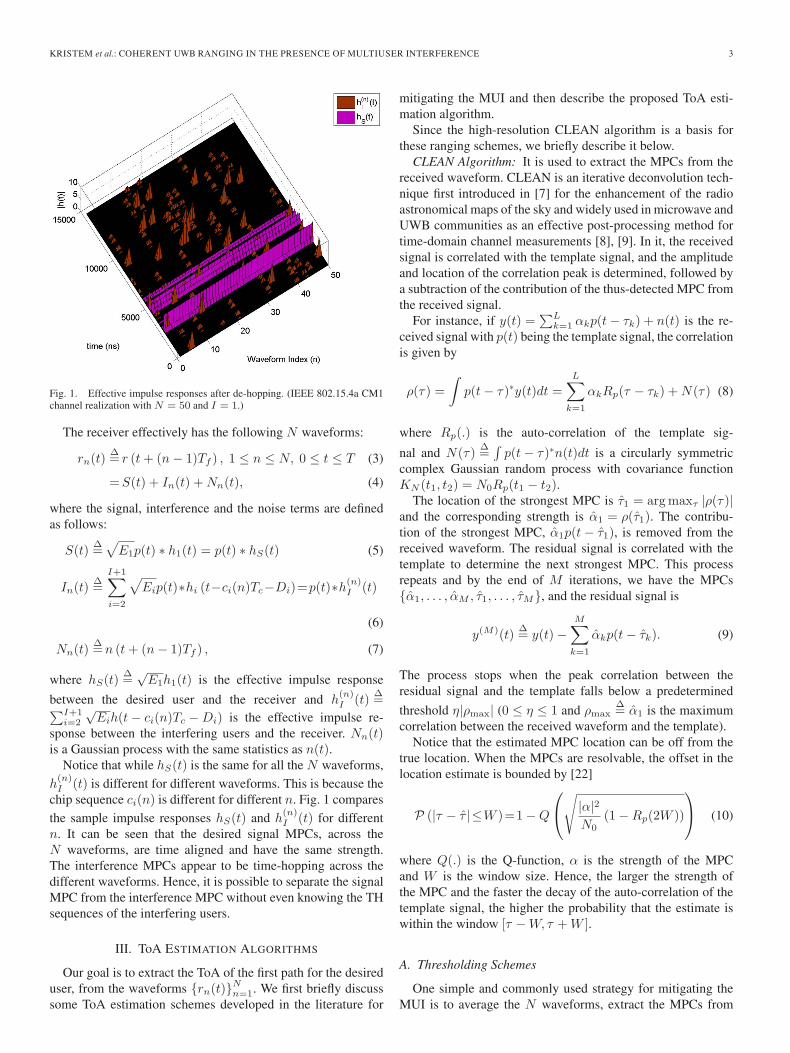
Fig. 1. Effective impulse responses after de-hopping. (IEEE 802.15.4a CM1channel realization with N = 50 and I = 1.)
The receiver effectively has the following N waveforms:
rn(t)Δ= r (t+ (n− 1)Tf ) , 1 ≤ n ≤ N, 0 ≤ t ≤ T (3)
=S(t) + In(t) +Nn(t), (4)
where the signal, interference and the noise terms are definedas follows:
S(t)Δ=√
E1p(t) ∗ h1(t) = p(t) ∗ hS(t) (5)
In(t)Δ=
I+1∑i=2
√Eip(t)∗hi (t−ci(n)Tc−Di)=p(t)∗h(n)
I (t)
(6)
Nn(t)Δ=n (t+ (n− 1)Tf ) , (7)
where hS(t)Δ=
√E1h1(t) is the effective impulse response
between the desired user and the receiver and h(n)I (t)
Δ=∑I+1
i=2
√Eih(t− ci(n)Tc −Di) is the effective impulse re-
sponse between the interfering users and the receiver. Nn(t)is a Gaussian process with the same statistics as n(t).
Notice that while hS(t) is the same for all the N waveforms,h(n)I (t) is different for different waveforms. This is because the
chip sequence ci(n) is different for different n. Fig. 1 comparesthe sample impulse responses hS(t) and h
(n)I (t) for different
n. It can be seen that the desired signal MPCs, across theN waveforms, are time aligned and have the same strength.The interference MPCs appear to be time-hopping across thedifferent waveforms. Hence, it is possible to separate the signalMPC from the interference MPC without even knowing the THsequences of the interfering users.
III. ToA ESTIMATION ALGORITHMS
Our goal is to extract the ToA of the first path for the desireduser, from the waveforms {rn(t)}Nn=1. We first briefly discusssome ToA estimation schemes developed in the literature for
mitigating the MUI and then describe the proposed ToA esti-mation algorithm.
Since the high-resolution CLEAN algorithm is a basis forthese ranging schemes, we briefly describe it below.
CLEAN Algorithm: It is used to extract the MPCs from thereceived waveform. CLEAN is an iterative deconvolution tech-nique first introduced in [7] for the enhancement of the radioastronomical maps of the sky and widely used in microwave andUWB communities as an effective post-processing method fortime-domain channel measurements [8], [9]. In it, the receivedsignal is correlated with the template signal, and the amplitudeand location of the correlation peak is determined, followed bya subtraction of the contribution of the thus-detected MPC fromthe received signal.
For instance, if y(t) =∑L
k=1 αkp(t− τk) + n(t) is the re-ceived signal with p(t) being the template signal, the correlationis given by
ρ(τ) =
∫p(t− τ)∗y(t)dt =
L∑k=1
αkRp(τ − τk) +N(τ) (8)
where Rp(.) is the auto-correlation of the template sig-
nal and N(τ)Δ=∫p(t− τ)∗n(t)dt is a circularly symmetric
complex Gaussian random process with covariance functionKN (t1, t2) = N0Rp(t1 − t2).
The location of the strongest MPC is τ1 = argmaxτ |ρ(τ)|and the corresponding strength is α1 = ρ(τ1). The contribu-tion of the strongest MPC, α1p(t− τ1), is removed from thereceived waveform. The residual signal is correlated with thetemplate to determine the next strongest MPC. This processrepeats and by the end of M iterations, we have the MPCs{α1, . . . , αM , τ1, . . . , τM}, and the residual signal is
y(M)(t)Δ= y(t)−
M∑k=1
αkp(t− τk). (9)
The process stops when the peak correlation between theresidual signal and the template falls below a predetermined
threshold η|ρmax| (0 ≤ η ≤ 1 and ρmaxΔ= α1 is the maximum
correlation between the received waveform and the template).Notice that the estimated MPC location can be off from the
true location. When the MPCs are resolvable, the offset in thelocation estimate is bounded by [22]
P (|τ − τ |≤W )=1−Q
⎛⎝√ |α|2N0
(1−Rp(2W ))
⎞⎠ (10)
where Q(.) is the Q-function, α is the strength of the MPCand W is the window size. Hence, the larger the strength ofthe MPC and the faster the decay of the auto-correlation of thetemplate signal, the higher the probability that the estimate iswithin the window [τ −W, τ +W ].
A. Thresholding Schemes
One simple and commonly used strategy for mitigating theMUI is to average the N waveforms, extract the MPCs from
4 IEEE TRANSACTIONS ON WIRELESS COMMUNICATIONS
the averaged waveform using CLEAN, use a good thresholdto separate the first arriving signal MPC from the interferenceMPCs and the noise peaks, and declare the MPC with thesmallest delay as the ToA estimate.
Notice that the ranging error is sensitive to the threshold η.In the presence of noise and/or MUI, finding a good thresholdis challenging. Setting large η can result in missing the weaksignal MPCs and a small η can result in early false alarms fromcapturing interference MPCs or noise peaks.
Averaging works well when N is very large or SIR is high.But in reality, N is limited by the coherence time of the channel.Since all users transmit with similar power level, SIR of 0 dBis typical and it can even attain a large negative value dueto near/far effects or LOS/NLOS situations. For a finite Nand a reasonable SIR, the residual interference after averagingcan be comparable to or larger than the first arriving MPCfrom the desired user. Hence, this approach can result in largemissed detection and early false alarms, thereby deterioratingthe ranging accuracy.
In the remainder of the paper two different thresholds areconsidered as benchmarks:
1) Genie Thresholding: For every channel realization, η ischosen to minimize the instantaneous ranging error. This isdone by performing the brute-force Monte Carlo simulations-based search. Note that this is not feasible in practice: to de-termine the instantaneous ranging error and hence the optimalη, we would have to know the instantaneous channel impulseresponse, which is the quantity we wish to measure.
2) Lookup Table Based Thresholding: η is chosen to mini-mize the mean-squared error (MSE) in the range estimates. Thiscan be realized in practice by forming a lookup table of optimalη for different SNR, SIR, I and N . The threshold is pickedbased on the operating conditions.
B. Proposed ToA Estimation Algorithm
By averaging the waveforms, we lose the information aboutthe location of the interference MPCs. Instead, we can firstdetermine the location of interference MPCs, remove theircontribution from each of the waveforms and then average theinterference-free waveforms and extract the ToA information.The algorithm has been summarized in Algorithm 1. We nowdescribe each of the steps in detail.
Algorithm 1: Proposed ToA estimation
Step 1: Impulse response extraction from waveformsfor n = 1 : N do
MPCs extraction from rn(t): {τ (n)k , α(n)k , 1≤k≤Ln}
Impulse response: hn(t)Δ=∑Ln
k=1 α(n)k δ(t− τ
(n)k )
endStep 2: Separating the interference/noise and signal MPCsfor n = 1 : N do
ΔIn = [ ], ΔS
n = [ ]for k = 1 : Ln
Accumulate MPCs in 2W window:Xm
Δ=∫Ww=−W hm(τ
(n)k − w)dw
Consider the set {Xm, 1 ≤ m ≤ N}.if ∃ a cluster of at least N non-zero data pointsaround Xk then
Declare τ(n)k as a signal MPC
Collect signal MPCs: ΔSn = [ΔS
n τ(n)k ]
elseDeclare τ (n)k as an interference/noise MPC
Collect interference MPCs: ΔIn=[Δ
In τ
(n)k ]
endend
endStep 3: Interference cancellation and noise averagingfor n = 1 : N do
rn(t) = rn(t)−∑
τ∈ΔInhn(τ)p(t− τ)
endNoise averaging: ravg(t) = (1/N)
∑Nn=1 rn(t).
Step 4: Range (or) ToA estimationMPC delay extraction from ravg(t): {τk, k ≥ 1}ToA = min{τk : |τk − τk+1| < (5.3/λ)}.
1) Impulse Response Extraction From the Waveforms: Weuse the CLEAN algorithm to extract the impulse responses fromeach of the N waveforms. We use a fixed correlation thresholdof μ
Δ= 2.12
√N0, so that the false alarm probability due to the
noise peak is small. A noise peak occurs at τ if the correlationexceeds the threshold; the probability of this event is
P (|ρ(τ)| > μ) = P (|N(τ)| > μ) = exp
(− μ2
N0
)= 0.01.
Let {τ (n)k , α(n)k , 1 ≤ k ≤ Ln} be the location and the strength
of the MPCs extracted from the waveform rn(t). The impulse
response is defined as hn(t)Δ=∑Ln
k=1 α(n)k δ(t− τ
(n)k ). Since
rn(t) has contributions from desired user, interfering users, andnoise, the MPC delay τ
(n)k can correspond to desired user or the
interfering users or the noise peak.2) Separating the Interference and Signal MPCs: Consider
the set {hn(τ), 1 ≤ n ≤ N}. As seen from Fig. 1, if τ corre-sponds to a signal MPC location, most of the values in the setare similar. If τ corresponds to a noise peak in one waveform,many of the values in the remainder of the set will be zerosince the odds of noise peaks happening at the same location inmultiple waveforms are low. If τ corresponds to an interferenceMPC location in one waveform, some of the values in theremainder of the set will be zero and even the non-zero valuesin the set are distinct. This is because an interference MPCtime-hops across the different waveforms as explained earlier.However, we also have to take into account that because ofnoise, the estimated MPC locations can vary around their truelocations. If τ is the true signal MPC location, because of i.i.d.noise in different waveforms, the offset in the location estimateis also i.i.d. across the waveforms, but with high probability theestimates will all lie in {τ −W, τ +W}. This can also be seenfrom Fig. 2, which plots the offset in the signal MPC locationestimates for the strongest five MPCs. It can be seen that the

KRISTEM et al.: COHERENT UWB RANGING IN THE PRESENCE OF MULTIUSER INTERFERENCE 5
Fig. 2. Error in MPC location estimates obtained using CLEAN, for fivestrongest MPCs. (IEEE 802.15.4a CM1 channel realization and second deriva-tive of basic Gaussian pulse with pulse width of 1 ns are used. N = 50,SNR = 30 dB, sampling time = 25 ps, and I = 0.)
amount of offset is inversely proportional to the strength of theMPC.
Using the intuition presented above, we now propose thefollowing heuristic rule to decide if the MPC location τ
(n)k
corresponds to a signal MPC or an interference/noise MPC.For 1 ≤ n ≤ N and 1 ≤ k ≤ Ln,
• Construct the set {Xn, 1 ≤ n ≤ N}, where XnΔ=∫W
w=−W hn(τ(n)k − w)dw. This is done to compensate for
the offset in the MPC location estimates. Let M be thenumber of non-zero values in this set.
• M < N : Declare τ(n)k as an interference/noise MPC (A
signal MPC will be detected in at least N out of Nwaveforms). N is an algorithm parameter that will bediscussed later.
• M ≥ N : If τ(n)k is an interference MPC, these M data
points are distinct and far apart. If it is a signal MPC, mostof these data points are clustered. In some of the wave-forms, an interference MPC can overlap with the signalMPC thereby deteriorating the MPC amplitude estimate.Since we do not assume the knowledge of strength ofinterference MPCs, we simply identify such estimates anddiscard them as below.
– Construct a circle of radius γ around every data pointand count the number of data points enclosed by thecircle (including the center).
– If there is no such circle enclosing at least N out of Mdata points, declare τ
(n)k as an interference MPC.
– If there is more than one circle enclosing N or moredata points, consider the circle enclosing maximumnumber of data points. If Xn is outside the circle,declare τ
(n)k as an interference MPC and if Xn is
inside, declare τ(n)k as a signal MPC.
Let ΔIn
Δ={τ (n)k , 1 ≤ k ≤ Ln | τ (n)k is an interference MPC}
be the collection of interference MPCs corresponding to the nth
received waveform, rn(t). Similarly, the collection of signal
MPCs is given by ΔSnΔ={τ (n)k , 1≤k≤Ln|τ (n)k is a signal MPC}.
3) Interference Cancellation and Noise Averaging: Noticethat we could have stopped once τ (n)k is detected as signal MPC.But doing so, we cannot take advantage of the increased SNRobtained from averaging the cleaned-up waveforms. Instead,we remove the contribution of thus detected interference MPCsfrom the waveforms, and average the cleaned-up waveforms toincrease the SNR.
rn(t) = rn(t)−∑τ∈ΔI
n
hn(τ)p(t− τ), 1 ≤ n ≤ N. (11)
Notice that the above steps remove strong interference andnoise peaks. The waveforms are now averaged to suppress anyweak residual interference and noise
ravg(t) =1
N
N∑n=1
rn(t). (12)
4) Range Extraction: Assuming that the interference is ef-fectively suppressed in the above steps, ravg(t) can be treatedas the received waveform in AWGN. We again use the CLEANalgorithm to extract the first MPC. To be fair in comparison,we chose the correlation threshold from the lookup table thatis generated for I = 0 (No interference case). We furthermorerequire that the delay between the first and second MPC isconsistent with the statistics of the inter-arrival times of MPCs,which is assumed to be known. This is required to filter outany residual interference MPCs, as their inter-arrival timeshas significantly larger delays than the signal MPCs.2 Whenthe MPC arrival times are modeled as Poisson process withparameter λ, probability that the inter-arrival times exceed5.3/λ is 0.5%.
Let the extracted MPCs location be {τk, k ≥ 1}. The ToAestimate is given by
ToA = min
{τk : |τk − τk+1| <
5.3
λ
}. (13)
IV. PROPOSED ALGORITHM ANALYSIS
We now analyze the performance of the proposed rangingscheme and study the impact of parameters W , γ and N . Tomake the analysis tractable we make the following modelingassumptions. The channel impulse responses of the users,{hi(t)}I+1
i=1 , are assumed i.i.d. random processes. For the ithuser, the arrival times of the MPCs are modeled as Poissonprocess with rate λ and the strength of the MPCs are assumedto be independent Rayleigh RVs. The chip sequence ci(n) areassumed i.i.d. across n (waveform index) and i (user index),and independent of the channel impulse responses.
2For instance, with 1% false alarm probability and I = 10 interfering users,the residual interference MPC inter-arrival times are exponential with mean100/λI = 10/λ. But, the signal MPC inter-arrival times are exponential withmean 1/λ.

6 IEEE TRANSACTIONS ON WIRELESS COMMUNICATIONS
Thus, the MPC arrival times corresponding to the delayedimpulse response hi(t− ci(n)Tc) also follow a Poisson processwith rate λ, for different i and n. Hence, the MPC arrivaltimes corresponding to the sum interference, h(n)
I (t), follow aPoisson process with rate λI , and are i.i.d. across n.
Henceforth, we use the following notation: fX(x) shall de-note the density function of RV X . P(A) and E[A] shall denotethe probability and expectation of A, respectively. SimilarlyP(A|B) shall denote the conditional probability of A given B.
A. False Alarms From a Noise Peak
We will now compute the probability that the algorithmfalsely detects a noise peak from CLEAN as a signal MPC. Letτ be the MPC location corresponding to a noise peak. Withoutloss of generality, we assume that a noise peak of strengthX1(|X1| > μ), occurs at τ , in the first waveform.
The algorithm makes false detection of τ as a signal MPC, ifat least N − 1 of the remaining N − 1 waveforms have a noisepeak in [τ −W, τ +W ] and there exists a circle of radius γenclosing at least N of these points, including X1. The falsealarm probability is upper bounded by
Pf,N ≤N∑
m=N
min
⎛⎜⎝[(N − 1
m− 1
)(1− 2W exp
(− μ2
N0
))N−m
×(2W exp
(− μ2
N0
))m−1],
⎡⎢⎣ m∑k=N
k
(m− 1
k − 1
) ∞∫0
1
N0exp
(− y
N0
)
×
⎛⎝1−Q1
⎛⎝√ 2y
N0,
√2γ2
N0
⎞⎠⎞⎠k−1
×Q1
⎛⎝√ 2y
N0,
√2γ2
N0
⎞⎠m−k
dy
⎤⎥⎦⎞⎟⎠
where Q1(., .) is the Marcum Q-function. The details are givenin Appendix A.
B. False Alarms From an Interference MPC
We will now compute the probability that the algorithmfalsely detects an interference MPC as a signal MPC. Withoutloss of generality, we assume that an interference MPC ofstrength X1(|X1| > μ) occurs at τ , in the first waveform. LetEI be the average energy of the interference MPCs.
The algorithm makes false detection of τ as a signal MPCif at least N − 1 of the remaining N − 1 waveforms have aninterference MPC in [τ −W, τ +W ] and there exists a circle
of radius γ enclosing at least N of these points, including X1.The false alarm probability is upper bounded by
Pf,I ≤N∑
m=N
min
⎛⎜⎝[(N − 1
m− 1
)(1− exp(−2WIλ))m−1
× exp (−2WI(N −m)λ)
],⎡⎢⎣ m∑
k=N
k
(m− 1
k − 1
) ∞∫0
1
EIexp
(− y
EI
)
×
⎛⎝1−Q1
⎛⎝√ 2y
EI,
√2γ2
EI
⎞⎠⎞⎠k−1
×Q1
⎛⎝√ 2y
EI,
√2γ2
EI
⎞⎠m−k
dy
⎤⎥⎦⎞⎟⎠ .
The details are given in Appendix B.
C. Signal MPC Detection
Consider a signal MPC with strength α and at location τ . Wewill now compute the probability that the algorithm detects τas a signal MPC.
The algorithm correctly detects τ as a signal MPC, if in atleast N of the N waveforms τ is detected as MPC and thereexists a circle of radius γ enclosing at least N of these points.The detection probability is lower bounded by
Pd ≥N∑
m=N
N−m∑k=0
m∑l=N
(N
m+ k
)(m+ k
m
)(m− 1
l − 1
)p(α)m
× (1− p(α))k exp (−2WλI(m+ k))
× (1− exp(−2WλI))N−m−k
×∞∫
max(μ−|α|,0)
q(α, r)l−1 (1− q(α, r))m−l
× r
πN0exp
(− r2
N0
)g(r)dr
where p(α) and q(α, r) are given in (26) and (29), respec-tively, g(r) is defined in Appendix C. The details are given inAppendix C.
D. Choice of Parameters N , γ, and W
From the analysis presented in the earlier section, it can beseen that as N increases, the false alarm from noise and interfer-ence decreases, but the signal MPC detection probability also

KRISTEM et al.: COHERENT UWB RANGING IN THE PRESENCE OF MULTIUSER INTERFERENCE 7
decreases. Similarly as γ or W increases, the detection prob-ability increases but the false alarms from noise and interfer-ence also increases. An optimized choice could be done basedon the bounds derived above; however this would require a3-dimensional grid search. We instead use a heuristic approachto find a good choice of parameters, and then use the bounds todemonstrate the effectiveness of these choices.
Probability of a noise peak occurring in the interval [τ −W, τ +W ], in any waveform is upper bounded using (19).Since noise in different waveforms is i.i.d., the expected numberof waveforms with a noise peak in the interval [τ −W, τ +W ]is upper bounded by
E [#waveforms with a noise peak in [τ −W, τ +W ]]
≤ 2WN exp
(− μ2
N0
). (14)
Hence, we chose N ≥ 2WN exp(−(μ2/N0)), so that the falsealarms from noise peak is small.
Probability of an interference MPC in the interval [τ −W, τ +W ], in any waveform is 1− exp(−2WλI). Since in-terference MPC arrival times in different waveforms are i.i.d.,the expected number of waveforms with an interference MPCin the interval [τ −W, τ +W ] is given by
E[#waveforms with an interference MPC in [τ−W,τ+W ]]
= N(1−exp(−2WIλ)) . (15)
Hence, we chose N ≥ N(1− exp(−2WIλ)), so that the falsealarms from interference is small.
Consider a signal MPC with strength α and at location τ .The expected number of waveforms in which an interferenceMPC also happens in [τ −W, τ +W ] is given by (15). Hence,on average only N exp(−2WIλ) waveforms are free frominterference at τ . For these waveforms free from interference,the estimated strength of the signal MPC at τ is Xk = α+Nk.The radius of the circle, γ, is chosen such that with highprobability, a circle centered around one point encloses theother points. Since |Xi −Xj |2 = |Ni −Nj |2 is an exponentialRV with mean 2N0, for γ∗ = 3
√N0, we have
P (|Xi −Xj | > γ∗) = P(|Ni −Nj |2 > 9N0
)= 0.01.
Also, we choose N ≤ N exp(−2WIλ), so that the probabilityof detection of signal MPC is high. Since the missed detectionof signal MPC is more critical than the false alarms, as thefalse alarms can be further suppressed by steps 3 and 4 of thealgorithm, we chose
N ∗ = min
[N exp(−2WIλ),max
(2WN exp
(− μ2
N0
),
N (1− exp(−2WIλ))
)]. (16)
The window size, W , should be small enough that the falsealarms from a noise peak and an interference MPC is small.On the other hand it must be large enough that a signal MPCis detected. We choose W such that any signal MPC location
Fig. 3. Performance bounds with (W ∗,γ∗,N∗) for N = 50 and 1/λ = 6 ns.
Fig. 4. Performance bounds with (W,γ, N) = (W ∗/3, γ∗/3, N∗/3) and(W,γ, N) = (2W ∗, 2γ∗, 2N∗) for N = 50, I = 5 and 1/λ = 6 ns.
estimate, obtained from CLEAN, is at most W samples awayfrom the true location. Setting 95% confidence interval for α =μ, in (10), we have
P (|τ − τ | ≥ W ∗) = Q
⎛⎝√ μ2
N0(1−Rp(2W ∗))
⎞⎠ = 0.05.
(17)
Using μ = 2.12√N0, we have W ∗ = 0.5R−1
p (0.4).We now study the bounds developed on the false alarm
and detection probability for the above choice of parameters.Fig. 3 plots the false alarm probability Pf,N and Pf,I as afunction of EI and the signal MPC detection probability Pd
as a function of |α|2. Performance is shown for I = 1, 5,and 10. It can be seen that the algorithm successfully rejectsstrong interference MPCs and also rejects the noise peakssignificantly. Weak residual interference MPCs can be furthersuppressed by steps 3 and 4 of the algorithm. The signal MPCdetection probability increases with |α|2. When the number ofinterfering users is large, an interference MPC overlaps with the

8 IEEE TRANSACTIONS ON WIRELESS COMMUNICATIONS
Fig. 5. Performance evaluation of different ranging schemes, as a function of SIR (SNR = 20 dB and N = 50).
signal MPC in several of the waveforms, and if the interferenceis strong, it makes the desired signal unrecognizable and hencethe algorithm misses the signal MPCs. For I = 10, the signalMPC detection probability is only 0.55. In Fig. 4, we justifythe choice of parameters (W ∗, γ∗, N ∗). For I = 5, we plotthe performance with significantly different choice of param-eters. The solid lines is the performance with (W,γ, N) =(W ∗/3, γ∗/3, N ∗/3). It has higher false alarms from noise andlower detection probability than (W ∗, γ∗, N ∗). The dotted linesis the performance with (W,γ, N) = (2W ∗, 2γ∗, 2N ∗). It hasvery poor signal MPC detection probability.
V. PERFORMANCE EVALUATION WITH
SYNTHETIC CHANNELS
We now evaluate the performance of the proposed rangingscheme and compare it with some of the well-studied schemesin the literature. The root mean square error (RMSE) in the
distance,√E[|d− d|2], is used as the performance metric.
Here, d is the true distance between the desired user and thereceiver, and d
Δ= cToA is the estimated distance with c =
3× 10⁸ being the speed of light.The following parameter settings were used. For the trans-
mit pulse, the second derivative of the basic Gaussian pulse,p(t) ∝ (1− 4π(t/Tp)
2) exp(−2π(t/Tp)2) is used with Tp =
1 ns. The parameters of the time-hopping signal are Tc = 4 ns
and Nc = 60(Tf = NcTc = 240 ns). The chip sequences ci(n)are generated i.i.d. from the set {0, 1, . . . , Nc − 1} with equalprobability. The performance was evaluated with 103 channelrealizations of the IEEE 802.15.4a CM1 (residential line-of-sight) channel model [2]. For each channel realization, the chipsequences of the I + 1 users and hence the corresponding time-hopping signals are regenerated independently. Three differentvalues of I (I = 1, I = 5, and I = 10) and two different valuesof N (N = 50 and N = 15) were considered; 1/λ = 6 ns wasused. The window size using (17) was W = 0.25 ns (10 sam-ples). N and γ are chosen as per the discussion in Section IV-D.The performance of the proposed ranging scheme is comparedwith the thresholding schemes described in Section III-A andthe non-linear filtering based energy detection schemes in [25]:for the minimum and median filtering, the performance isoptimized over the block energy threshold and the length ofthe filter; the search back window size is fixed to 60 ns. We firstpresent the results with interference from different users beingthe same. For the later part of simulations, we also model thepath loss and shadowing and hence different SIR from differentinterfering users.
Fig. 5 compares the RMSE of different ranging schemes,as a function of SIR, for a fixed SNR of 20 dB and N = 50waveforms. Performance was shown for I = 1, I = 5, andI = 10. From (16), the corresponding N are 12, 17, and 22. Asmentioned earlier, we assume E2 = E3 = · · · = EI+1. As ex-pected, for the thresholding schemes, the RMSE decreases with

KRISTEM et al.: COHERENT UWB RANGING IN THE PRESENCE OF MULTIUSER INTERFERENCE 9
Fig. 6. Performance evaluation of different ranging schemes, as a functionof SNR, in presence of one active interfering user (SIR = 0 dB, I = 1, andN = 50).
SIR. Also, for these schemes, RMSE significantly increaseswith I in the interference limited regime. In the interferencelimited regime, the residual interference after averaging is com-parable to the strength of the LOS component from the desireduser and hence even a genie thresholding scheme has a largeRMSE. The proposed ranging scheme effectively suppressesthe strong interference MPCs (can also be seen from Fig. 3), andhence reduces the RMSE significantly, and performs equallywell at all SIR.
Notice that the proposed ranging scheme is always betterthan the minimum and median filtering schemes, is better thanthe lookup table thresholding scheme for SIR ≤ 8 dB, andis even better than the genie thresholding scheme for SIR ≤−8 dB. In the noise limited regime, averaging is the best thingto do and hence the lookup table thresholding scheme is slightlybetter than the proposed ranging scheme. While the proposedranging scheme can eliminate noise peaks, it also misses weaksignal MPCs resulting in increased RMSE. Also, evident is therobustness of the proposed ranging scheme to the strength ofthe interference and the number of interfering users. While theRMSE is very similar for I = 1 and I = 5 in the interferencelimited regime, it slightly increases for I = 10. For large I , theproposed ranging scheme has a lower signal MPC detectionprobability as discussed in Fig. 3, and hence increased RMSE.
Similar observations hold even for other values of N . For ex-ample, with N = 15 waveforms, the proposed ranging schemeis better than the lookup table thresholding scheme for SIR ≤10 dB, it is better than even the genie thresholding scheme forSIR ≤ −4 dB and is better than median and minimum filteringschemes at all SIR. The corresponding figure is not shown forlack of space. In general, the smaller the N , the better is theperformance of the proposed ranging scheme relative to thethresholding schemes.
Fig. 6 plots the RMSE of different ranging schemes as afunction of SNR, for SIR = 0 dB and I = 1. As expected, theRMSE decreases with SNR for all the ranging schemes in thenoise limited regime. When SNR is low (noise limited regime),
Fig. 7. Performance evaluation of different ranging schemes, as a function oftransmit power, when SIR from different users is different (N = 50).
averaging is better than any non-linear filtering and henceboth the thresholding schemes outperform the proposed rangingscheme. Beyond 16 dB SNR, interference is comparable tonoise and hence the proposed ranging scheme performs betterthan the lookup table based thresholding scheme. However, it isstill inferior to the genie scheme, which can change thresholdevery channel realization. Please note that the genie scheme isunrealistic and is only used as a benchmark.
So far we had implicitly assumed that all the interferingusers are at same distance from the receiver and hence causethe same amount of interference. We now model the userlocations using a Poisson point process in a two dimensionalplane. The path loss and shadowing are modeled as per thespecifications in the IEEE 802.15.4a CM1 channel model. Weassume all the users (both desired and interfering) transmitwith the same power level Ptx. Since different interferingusers are at different distance from the receiver, the receivedpower from the interfering users (Ek ∝ Ptxd
−nk ) is different for
different k.Fig. 7 compares the RMSE with different ranging schemes
as a function of Ptx and for different I . Notice that as Ptx
increases, the SNR increases but the SIR remains the same.For small Ptx, the system is in noise limited regime and hencethe ranging error decreases with Ptx. As mentioned earlier, inthe noise dominated regime, averaging is better than non-linearfiltering and hence the thresholding schemes perform betterthan the proposed ranging scheme. Beyond certain Ptx, the sys-tem is in the interference limited regime and hence the perfor-mance does not change with Ptx for the thresholding schemes.However, for the proposed scheme, which can suppress theinterference, the ranging error decreases with increasing Ptx.Notice that the proposed scheme is better than lookup tablethresholding schemes beyond Ptx = 5 dBm, is also better thanthe genie thresholding scheme for Ptx ≥ 15 dBm, and is alwaysbetter than the minimum and median filtering schemes. Forlarge Ptx, the RMSE with the proposed ranging scheme slightlyincreases and this is more significant for I = 10. This can be
10 IEEE TRANSACTIONS ON WIRELESS COMMUNICATIONS
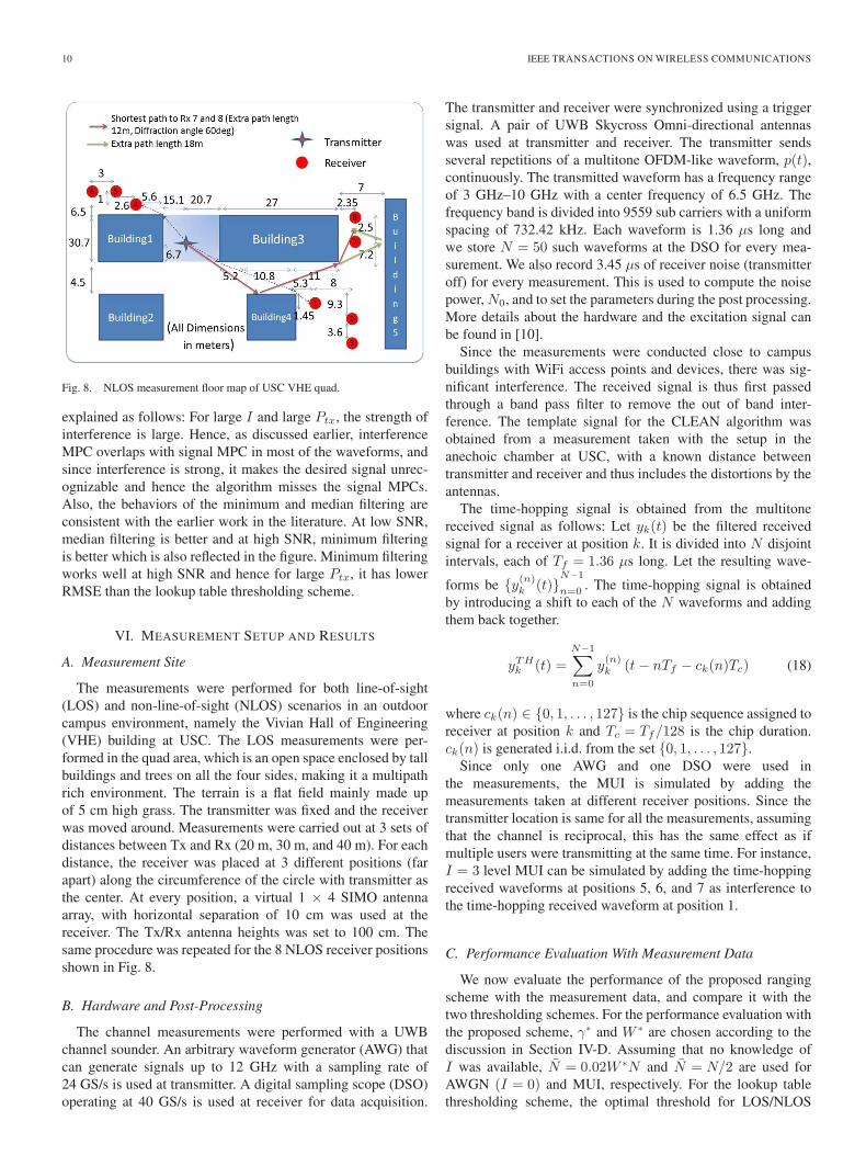
Fig. 8. NLOS measurement floor map of USC VHE quad.
explained as follows: For large I and large Ptx, the strength ofinterference is large. Hence, as discussed earlier, interferenceMPC overlaps with signal MPC in most of the waveforms, andsince interference is strong, it makes the desired signal unrec-ognizable and hence the algorithm misses the signal MPCs.Also, the behaviors of the minimum and median filtering areconsistent with the earlier work in the literature. At low SNR,median filtering is better and at high SNR, minimum filteringis better which is also reflected in the figure. Minimum filteringworks well at high SNR and hence for large Ptx, it has lowerRMSE than the lookup table thresholding scheme.
VI. MEASUREMENT SETUP AND RESULTS
A. Measurement Site
The measurements were performed for both line-of-sight(LOS) and non-line-of-sight (NLOS) scenarios in an outdoorcampus environment, namely the Vivian Hall of Engineering(VHE) building at USC. The LOS measurements were per-formed in the quad area, which is an open space enclosed by tallbuildings and trees on all the four sides, making it a multipathrich environment. The terrain is a flat field mainly made upof 5 cm high grass. The transmitter was fixed and the receiverwas moved around. Measurements were carried out at 3 sets ofdistances between Tx and Rx (20 m, 30 m, and 40 m). For eachdistance, the receiver was placed at 3 different positions (farapart) along the circumference of the circle with transmitter asthe center. At every position, a virtual 1 × 4 SIMO antennaarray, with horizontal separation of 10 cm was used at thereceiver. The Tx/Rx antenna heights was set to 100 cm. Thesame procedure was repeated for the 8 NLOS receiver positionsshown in Fig. 8.
B. Hardware and Post-Processing
The channel measurements were performed with a UWBchannel sounder. An arbitrary waveform generator (AWG) thatcan generate signals up to 12 GHz with a sampling rate of24 GS/s is used at transmitter. A digital sampling scope (DSO)operating at 40 GS/s is used at receiver for data acquisition.
The transmitter and receiver were synchronized using a triggersignal. A pair of UWB Skycross Omni-directional antennaswas used at transmitter and receiver. The transmitter sendsseveral repetitions of a multitone OFDM-like waveform, p(t),continuously. The transmitted waveform has a frequency rangeof 3 GHz–10 GHz with a center frequency of 6.5 GHz. Thefrequency band is divided into 9559 sub carriers with a uniformspacing of 732.42 kHz. Each waveform is 1.36 μs long andwe store N = 50 such waveforms at the DSO for every mea-surement. We also record 3.45 μs of receiver noise (transmitteroff) for every measurement. This is used to compute the noisepower, N0, and to set the parameters during the post processing.More details about the hardware and the excitation signal canbe found in [10].
Since the measurements were conducted close to campusbuildings with WiFi access points and devices, there was sig-nificant interference. The received signal is thus first passedthrough a band pass filter to remove the out of band inter-ference. The template signal for the CLEAN algorithm wasobtained from a measurement taken with the setup in theanechoic chamber at USC, with a known distance betweentransmitter and receiver and thus includes the distortions by theantennas.
The time-hopping signal is obtained from the multitonereceived signal as follows: Let yk(t) be the filtered receivedsignal for a receiver at position k. It is divided into N disjointintervals, each of Tf = 1.36 μs long. Let the resulting wave-
forms be {y(n)k (t)}N−1
n=0 . The time-hopping signal is obtainedby introducing a shift to each of the N waveforms and addingthem back together.
yTHk (t) =
N−1∑n=0
y(n)k (t− nTf − ck(n)Tc) (18)
where ck(n) ∈ {0, 1, . . . , 127} is the chip sequence assigned toreceiver at position k and Tc = Tf/128 is the chip duration.ck(n) is generated i.i.d. from the set {0, 1, . . . , 127}.
Since only one AWG and one DSO were used inthe measurements, the MUI is simulated by adding themeasurements taken at different receiver positions. Since thetransmitter location is same for all the measurements, assumingthat the channel is reciprocal, this has the same effect as ifmultiple users were transmitting at the same time. For instance,I = 3 level MUI can be simulated by adding the time-hoppingreceived waveforms at positions 5, 6, and 7 as interference tothe time-hopping received waveform at position 1.
C. Performance Evaluation With Measurement Data
We now evaluate the performance of the proposed rangingscheme with the measurement data, and compare it with thetwo thresholding schemes. For the performance evaluation withthe proposed scheme, γ∗ and W ∗ are chosen according to thediscussion in Section IV-D. Assuming that no knowledge ofI was available, N = 0.02W ∗N and N = N/2 are used forAWGN (I = 0) and MUI, respectively. For the lookup tablethresholding scheme, the optimal threshold for LOS/NLOS
KRISTEM et al.: COHERENT UWB RANGING IN THE PRESENCE OF MULTIUSER INTERFERENCE 11
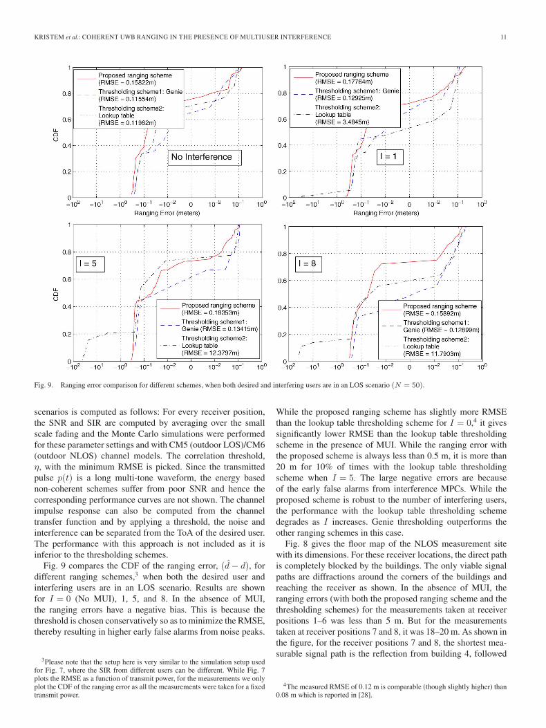
Fig. 9. Ranging error comparison for different schemes, when both desired and interfering users are in an LOS scenario (N = 50).
scenarios is computed as follows: For every receiver position,the SNR and SIR are computed by averaging over the smallscale fading and the Monte Carlo simulations were performedfor these parameter settings and with CM5 (outdoor LOS)/CM6(outdoor NLOS) channel models. The correlation threshold,η, with the minimum RMSE is picked. Since the transmittedpulse p(t) is a long multi-tone waveform, the energy basednon-coherent schemes suffer from poor SNR and hence thecorresponding performance curves are not shown. The channelimpulse response can also be computed from the channeltransfer function and by applying a threshold, the noise andinterference can be separated from the ToA of the desired user.The performance with this approach is not included as it isinferior to the thresholding schemes.
Fig. 9 compares the CDF of the ranging error, (d− d), fordifferent ranging schemes,3 when both the desired user andinterfering users are in an LOS scenario. Results are shownfor I = 0 (No MUI), 1, 5, and 8. In the absence of MUI,the ranging errors have a negative bias. This is because thethreshold is chosen conservatively so as to minimize the RMSE,thereby resulting in higher early false alarms from noise peaks.
3Please note that the setup here is very similar to the simulation setup usedfor Fig. 7, where the SIR from different users can be different. While Fig. 7plots the RMSE as a function of transmit power, for the measurements we onlyplot the CDF of the ranging error as all the measurements were taken for a fixedtransmit power.
While the proposed ranging scheme has slightly more RMSEthan the lookup table thresholding scheme for I = 0,4 it givessignificantly lower RMSE than the lookup table thresholdingscheme in the presence of MUI. While the ranging error withthe proposed scheme is always less than 0.5 m, it is more than20 m for 10% of times with the lookup table thresholdingscheme when I = 5. The large negative errors are becauseof the early false alarms from interference MPCs. While theproposed scheme is robust to the number of interfering users,the performance with the lookup table thresholding schemedegrades as I increases. Genie thresholding outperforms theother ranging schemes in this case.
Fig. 8 gives the floor map of the NLOS measurement sitewith its dimensions. For these receiver locations, the direct pathis completely blocked by the buildings. The only viable signalpaths are diffractions around the corners of the buildings andreaching the receiver as shown. In the absence of MUI, theranging errors (with both the proposed ranging scheme and thethresholding schemes) for the measurements taken at receiverpositions 1–6 was less than 5 m. But for the measurementstaken at receiver positions 7 and 8, it was 18–20 m. As shown inthe figure, for the receiver positions 7 and 8, the shortest mea-surable signal path is the reflection from building 4, followed
4The measured RMSE of 0.12 m is comparable (though slightly higher) than0.08 m which is reported in [28].

12 IEEE TRANSACTIONS ON WIRELESS COMMUNICATIONS
Fig. 10. Ranging error comparison for different schemes, when both desired and interfering users are in NLOS scenario (N = 50).
by diffraction at building 3. This path length is 12 m largerthan the Euclidean distance between transmitter and receiver.However, the diffraction angle at building 3 is 60 degrees.Hence, the ray undergoes significant loss from diffraction andthe corresponding MPC is not detectable. The next shortestpath is from double reflection at buildings 4 and 5 as shownin Fig. 8. This path length is 18 m more than the Euclideandistance. Since the RMSE is dominated by receiver positions 7and 8, we exclude the corresponding measurements for theperformance comparison of different ranging schemes. Resultsincluding these receiver positions are given in [5].
Fig. 10 compares the CDF of the ranging error for differentranging schemes, when both the desired user and interfer-ing users are in the NLOS scenario. In the AWGN channel(no MUI), all the three schemes have positive bias in theranging error, as the direct path is blocked by the buildings.The proposed ranging scheme is as good as the lookup tablethresholding scheme. Even with just one interfering user, theproposed scheme gives considerably lower RMSE than boththe thresholding schemes. While the ranging error with the pro-posed scheme is always less than 5 m, it can be more than 15 mwith the thresholding schemes. While the proposed scheme isrobust to the number of interfering users, the performance withthe thresholding schemes degrades as I increases. The impact
of MUI is more significant in NLOS scenarios and even thegenie thresholding scheme cannot suppress the MUI effectively.
VII. CONCLUSION
In this paper, we proposed a novel coherent ranging al-gorithm to mitigate the MUI. We considered time-hoppingimpulse radio. We observed that after de-hopping the receivedsignal, receiver effectively sees multiple waveforms in whichsignal MPC occurs at same location, but interference MPClocation for different waveforms is different. Using this obser-vation, we were able to separate the interference MPCs andhence remove their contribution from the received signal. Wealso derived the performance bounds with the proposed rangingscheme. Using the IEEE 802.15.4a CM1 channel model as wellas measured data, we showed the robustness of the proposedranging scheme to the strength of interference and the numberof interfering users.
APPENDIX AFALSE ALARMS FROM A NOISE PEAK
A noise peak occurs in the interval [τ −W, τ +W ], in thekth waveform (k > 1), if |Nk(t)| > μ for some t ∈ [τ −W,

KRISTEM et al.: COHERENT UWB RANGING IN THE PRESENCE OF MULTIUSER INTERFERENCE 13
τ +W ]. It can be upper bounded as
P(Noise peak in [τ −W, τ +W ] in kth waveform
)= P (∃t ∈ [τ −W, τ +W ], |Nk(t)| > μ)
≤ 2WP(|Nk(t)|2 > μ2
)= 2W exp
(− μ2
N0
). (19)
Since it is assumed that the noise peak happens in the firstwaveform, the algorithm makes false detection of τ as a signalMPC, if at least N − 1 of the N − 1 waveforms have a noisepeak in [τ −W, τ +W ] and there exists a circle of radiusγ enclosing at least N of these points, including X1. Let
Event 1Δ= {m− 1 out of N − 1 waveforms have a noise peak
in [τ −W, τ +W ]} and Event 2Δ= {∃ circle enclosing at least
N of m points, including X1}. The false alarm probability canbe upper bounded by
Pf,N ≤N∑
m=N
P(Event 1,Event 2)
≤N∑
m=N
min (P(Event 1),P(Event 2)) . (20)
Using (19), we have P(Event 1) ≤(N−1m−1
)(2W exp(−(μ2/
N0)))m−1(1− 2W exp(−(μ2/N0)))
N−m.Let X1, X2, . . . , Xm be the strength of the m noise peaks
(|Xi| > μ). Using the union bound
P(Event 2)
≤m∑l=1
P(at least N of m points, including X1,
enclosed by circle around Xl)
= (m− 1)P(at least N of m points, including X1,
enclosed by circle around X2)
+ P(at least N of m points are enclosed
by circle around X1). (21)
We will now evaluate each of the above two terms. The firstterm is given by
P(at least N of m points, including X1,
enclosed by circle with center X2 and radius γ)
=
m∑k=N
(m−2
k−2
)P
⎛⎝|X1 −X2| < γ,
k∏j=3
|Xj −X2| < γ,
m∏j=k+1
|Xj −X2| > γ
⎞⎠=
m∑k=N
(m−2
k−2
)∫P(|X1−x2|<γ)
k∏j=3
P(|Xj−x2|<γ)
×m∏
j=k+1
P (|Xj − x2| > γ) fX2(x2)dx2
=m∑
k=N
(m− 2
k − 2
) ∞∫0
⎛⎝1−Q1
⎛⎝√ 2y
N0,
√2γ2
N0
⎞⎠⎞⎠k−1
×Q1
⎛⎝√ 2y
N0,
√2γ2
N0
⎞⎠m−k
1
N0exp
(− y
N0
)dy, (22)
where Q1(., .) is the Marcum Q-function. We have used the factthat {|Xi|2}mi=1 are i.i.d. exponential RVs with mean N0 and{|Xi − x2|}mi=3 are i.i.d. Rice RVs with parameters |x2| and√N0/2 [1]. The second term in (21) can similarly be shown
to be
P(at least N of m points are enclosed by circle
with center X1 and radius γ)
=
m∑k=N
(m− 1
k − 1
) ∞∫0
⎛⎝1−Q1
⎛⎝√ 2y
N0,
√2γ2
N0
⎞⎠⎞⎠k−1
×Q1
⎛⎝√ 2y
N0,
√2γ2
N0
⎞⎠m−k
1
N0exp
(− y
N0
)dy. (23)
Using (22) and (23) in (21) and further using it in (20), thefalse alarm probability from a noise peak follows after somesimplification.
APPENDIX BFALSE ALARMS FROM AN INTERFERENCE MPC
An interference peak occurs in the interval [τ −W, τ +W ],in the kth waveform (k > 1), if at least one interference MPCarrives in the interval [τ −W, τ +W ], and the strength of theinterference exceeds the threshold μ. Since μ is small, weassume that the strength of interference always exceeds thethreshold whenever an interference MPC arrives in [τ −W, τ +W ]. Hence, the probability of an interference peak is upperbounded by
P (Interference peak in [τ −W, τ +W ],
in the kth waveform)
≤ P (at least one interference MPC arrives in
[τ −W, τ +W ])
= 1− exp(−2WIλ). (24)
We have used the fact that interference MPC arrivals arePoisson distributed with parameter λI . Since it is assumedthat an interference peak happens in the first waveform, thealgorithm makes false detection of τ as a signal MPC if at leastN − 1 of the N − 1 waveforms have an interference peak in[τ −W, τ +W ] and there exists a circle of radius γ enclosing
at least N of these points, including X1. Let Event 1Δ= {m− 1
out of N − 1 waveforms has interference peak in [τ −W,
τ +W ]} and Event 2Δ= {∃ circle enclosing at least N of m

14 IEEE TRANSACTIONS ON WIRELESS COMMUNICATIONS
points, including X1}. The false alarm probability is upperbounded by
Pf,I ≤N∑
m=N
P(Event 1,Event 2)
≤N∑
m=N
min (P(Event 1),P(Event 2)) . (25)
Using (24), we have P(Event 1)≤(N−1m−1
)(1−exp(−2WIλ))m−1
exp(−2WI(N −m)λ).Event 2 is very similar to the noise case, except that
{|Xi|2}mi=1 are now i.i.d. exponential RVs with mean EI .Hence, replacing N0 with EI in (22) and (23), and further usingit in (25), the false alarm probability from an interference peakfollows.
APPENDIX CSIGNAL MPC DETECTION
A signal MPC is detected in the interval [τ −W, τ +W ],in the kth waveform if the offset in the location estimate byCLEAN is less than W and the strength of the estimate, Xk =α+Nk, exceeds the threshold μ. The detection probability isgiven by
p(α)Δ=P (signal MPC is detected in [τ −W, τ +W ],
in the kth waveform)
≈P (|τ − τ | ≤ W )P (|Xk| > μ)
=
⎛⎝1−Q
⎛⎝√ |α|2N0
(1−Rp(2W ))
⎞⎠⎞⎠×Q1
⎛⎝√2|α|2N0
,
√2μ2
N0
⎞⎠ . (26)
For some of the waveforms, an interference MPC can overlap
with the signal MPC at τ . Let Event 1Δ= { No interference in
[τ −W, τ +W ], in m+ k out of N waveforms}, Event 2Δ=
{Signal MPC detected in [τ −W, τ +W ], in m out of m+ k}waveforms, and Event 3
Δ= {∃ circle enclosing at least N out of
m points }. We assume that interference is strong enough thatthe resulting MPC estimates at τ in these waveforms are faraway from true value, α, and hence will be outside the circle.Hence, the detection probability is lower bounded by
Pd ≥N∑
m=N
N−m∑k=0
P(Event 1,Event 2,Event 3)
=
N∑m=N
N−m∑k=0
P(Event 1)P(Event 2|Event 1)
× P(Event 3|Event 1,Event 2). (27)
Using (24), we have P(Event 1) =(
Nm+k
)exp(−2WλI(m+
k))(1− exp(−2WλI))N−m−k.
Using (26), we have P(Event 2|Event 1) =(m+km
)p(α)m
(1− p(α))k. We will now evaluate the conditional probability
term. Let {XiΔ= α+Ni, 1 ≤ i ≤ m} be the strength of the m
detected MPCs that are free from interference. The conditionalprobability can be lower bounded as
P(Event 3|Event 2,Event 1)
≥ P(circle centered at X1 with radius γ encloses
at least N points|Event 1,Event 2)
=
m∑l=N
(m− 1
l − 1
)
× P
⎛⎝ l∏j=2
|Nj−N1|<γ,
m∏j=l+1
|Nj −N1|>γ
∣∣∣∣|α+N1|
> μ, . . . , |α+Nm| > μ
)
=
m∑l=N
(m−1
l−1
) ∫n1:|α+n1|>μ
P(|N−n1| < γ
∣∣∣∣|α+N |>μ
)l−1
× P(|N − n1| > γ
∣∣∣∣|α+N | > μ
)m−l
fN1(n1) dn1. (28)
The conditional probability term in (28) can be written as
P(|N − n1| < γ
∣∣∣∣|α+N | > μ) =P(|N − n1| < γ, |α+N | >
μ)P(|α+N | > μ)−1. Since N is a complex GaussianRV with variance N0, we have P(|α+N | > μ) =
Q1(√2|α|2/N0,
√2μ2/N0). Since μ
Δ= 2.12
√N0 is small,
for |α|2 � N0, we have P(|N − n1| < γ, |α+N | > μ) ≈P(|N − n1| < γ) =1−Q1(
√2|n1|2/N0,
√2γ2/N0). Hence,
we have
q (α, |n1|) Δ=P(|N − n1| < γ
∣∣∣∣|α+N | > μ
)
≈
⎛⎝1−Q1
⎛⎝√2|n1|2N0
,
√2γ2
N0
⎞⎠⎞⎠×Q1
⎛⎝√2|α|2N0
,
√2μ2
N0
⎞⎠−1
. (29)
Note that |N1| is a Rayleigh RV and ∠N1 is a uniform RV.Rewriting the integral in (28) in polar coordinates and evalu-
ating it over ∠N1, we get∫ ∫r,θ:cos(θ−∠α)>
μ2−|α|2−r2
2r|α|
q(α, r)l−1 (1− q(α, r))m−l
× r
πN0exp
(− r2
N0
)dr dθ
=
∞∫max(μ−|α|,0)
q(α, r)l−1 (1− q(α, r))m−l
× r
πN0exp
(− r2
N0
)g(r)dr, (30)

KRISTEM et al.: COHERENT UWB RANGING IN THE PRESENCE OF MULTIUSER INTERFERENCE 15
where g(r) = 2 cos−1((μ2 − |α|2 − r2)/2r|α|) for r ∈ (|μ−|α||, |α|+ μ) and is 2π otherwise.
Hence, the detection probability follows.
ACKNOWLEDGMENT
We thank H. Feng, S. Aditya and R. Wang for their help withthe measurements, Dr. Alan Willner for providing test and mea-surement equipment for initial measurements, A. Voskoboinik,S. Khaleghi, and H. Huang for their help with the hardwarecomponents.
REFERENCES
[1] A. F. Molisch, Wireless Communications, 2nd ed. Piscataway, NJ, USA:IEEE Press/Wiley, 2011.
[2] A. F. Molisch et al., “A comprehensive standardized model for ultraw-ideband propagation channels,” IEEE Trans. Antennas Propag., vol. 54,no. 11, pp. 3151–3166, Nov. 2006.
[3] P. Bahl and V. N. Padmanabhan, “RADAR: An in-building RF-baseduser location and tracking system,” in Proc. IEEE INFOCOM, 2000,pp. 775–784.
[4] B. Li, A. G. Dempster, J. Barnes, C. Rizos, and D. Li, “Probabilisticalgorithm to support the fingerprinting method for CDMA location,” inProc. Int. Symp. On GPS/GNSS, Hong Kong, Dec. 8–10, 2005, pp. 1–8.
[5] V. Kristem, S. Niranjayan, S. Sangodoyin, and A. F. Molisch, “Experi-mental determination of UWB ranging errors in an outdoor environment,”in Proc. IEEE ICC, Sydney, Australia, Jun. 2014.
[6] M. Z. Win and R. A. Scholtz, “Impulse radio: How it works,” IEEECommun. Lett., vol. 2, no. 2, pp. 36–38, Feb. 1998.
[7] J. A. Hogbom, “Aperture synthesis with a non-regular distribution ofinterferometer baselines,” Astron. Astrophys., vol. 15, pp. 417–426,Jun. 1974.
[8] R. J. M. Cramer, R. A. Scholtz, and M. Z. Win, “Evaluation of an ultra-wide-band propagation channel,” IEEE Trans. Antennas Propag., vol. 50,no. 5, pp. 561–570, May 2002.
[9] A. Muqaibel, A. Safaai-Jazi, B. Woerner, and S. Riad, “UWB channel im-pulse response characterization using deconvolution techniques,” in Proc.45th Midwest Symp. Circuits Syst., Aug. 2002, vol. 3, pp. III-605–III-608.
[10] S. Sangodoyin, S. Niranjayan, and A. F. Molisch, “Ultrawideband near-ground outdoor propagation channel measurements and modeling,” inProc. 7th EuCAP, Gothenburg, Sweden, Apr. 2013, pp. 3034–3038.
[11] H. L. Van Trees, Detection, Estimation, Modulation Theory. Hoboken,NJ, USA: Wiley, 1968.
[12] S. Bellini and G. Tartara, “Bounds on error in signal parameter es-timation,” IEEE Trans. Commun., vol. COM-22, no. 3, pp. 340–342,Mar. 1974.
[13] D. Chazan, M. Zakai, and J. Ziv, “Improved lower bounds on signal pa-rameter estimation,” IEEE Trans. Inf. Theory, vol. IT-21, no. 1, pp. 90–93,Jan. 1975.
[14] J. Zhang, R. A. Kennedy, and T. D. Abhayapala, “Cramer-Rao lowerbounds for the synchronization of UWB signals,” EURASIP J. WirelessCommun. Netw., vol. 2005, no. 3, p. 293 649, Mar. 2005.
[15] D. Dardari, C. C. Chong, and M. Z. Win, “Improved lower bounds ontime-of-arrival estimation error in realistic UWB channels,” in Proc. IEEEICUWB, 2006, pp. 531–537.
[16] M. Z. Win and R. A. Scholtz, “Characterization of ultra-wide bandwidthwireless indoor communications channel: A communication theoreticview,” IEEE J. Sel. Areas Commun., vol. 20, no. 9, pp. 1613–1627,Dec. 2002.
[17] H. Saarnisaari, “ML time delay estimation in a multipath channel,” inProc. IEEE ISSTA, 1996, pp. 1007–1011.
[18] J. Y. Lee and R. A. Scholtz, “Ranging in a dense multipath environmentusing an UWB radio link,” IEEE J. Sel. Areas Commun., vol. 20, no. 9,pp. 1677–1683, Sep. 2002.
[19] C. Falsi, D. Dardari, L. Mucchi, and M. Z. Win, “Time of arrival esti-mation for UWB localizers in realistic environments,” EURASIP J. Appl.Signal Process., vol. 2006, no. 1, pp. 1–13, Jul. 2006.
[20] I. Guvenc and Z. Sahinoglu, “Threshold-based TOA estimation for im-pulse radio UWB systems,” in Proc. IEEE ICUWB, 2005, pp. 420–425.
[21] I. Guvenc, Z. Sahinoglu, A. F. Molisch, and P. Orlik, “Non-coherent TOAestimation in IR-UWB systems with different signal waveforms,” in Proc.IEEE BROADNETS, 2005, vol. 2, pp. 1168–1174.
[22] D. Dardari, A. Conti, U. Ferner, A. Giorgetti, and M. Z. Win, “Rang-ing with ultrawide bandwidth signals in multipath environments,” Proc.IEEE, vol. 97, no. 2, pp. 404–426, Feb. 2009.
[23] S. Gezici, Z. Sahinoglu, A. F. Molisch, H. Kobayashi, and H. V. Poor,“Two-step time of arrival estimation for pulse-based ultra-wideband sys-tems,” EURASIP J. Adv. Signal Process., vol. 2008, no. 1, p. 529 134,May 2008.
[24] A. Giorgetti and M. Chiani, “Time-of-arrival estimation based on infor-mation theoretic criteria,” IEEE Trans. Signal Process., vol. 61, no. 8,pp. 1869–1879, Apr. 2013.
[25] Z. Sahinoglu and I. Guvenc, “Multiuser interference mitigation in non-coherent UWB ranging via nonlinear filtering,” EURASIP J. WirelessCommun. Netw., vol. 2006, no. 1, pp. 1–10, Sep. 2006.
[26] D. Dardari, A. Giorgetti, and M. Z. Win, “Time-of-arrival estimation ofUWB signals in the presence of narrowband and wideband interference,”in Proc. IEEE ICUWB, 2007, pp. 71–76.
[27] A. G. Amigo, A. Mallat, and L. Vandendorpe, “Multiuser and multipathinterference mitigation in UWB TOA estimation,” in Proc. IEEE ICUWB,2011, pp. 465–469.
[28] Y. Zhou, C. L. Law, J. Xia, and K. S. Koh, “Long range UWB localizationsystem: From design to measurement,” in Proc. IEEE ICUWB, 2010,pp. 1–4.
Vinod Kristem received the B.Tech. degree in elec-tronics and communications engineering from theNational Institute of Technology (NIT), Warangal,India, in 2007 and the M.Sc.Eng. degree in telecom-munications from the Department of Electrical Com-munication Engineering, Indian Institute of Science,Bangalore, India in 2009. He is currently work-ing toward his Ph.D. degree with the Departmentof Electrical Engineering, University of SouthernCalifornia, Los Angeles. From 2009 to 2011, he waswith Beceem Communications Pvt. Ltd., Bangalore,
India (which was recently acquired by Broadcom Corp.), where he worked onchannel estimation and physical layer measurements for WiMAX and LTE.His research interests include Antenna selection in MIMO systems, channelmodeling, UWB ranging and localization.
Andreas F. Molisch (S’89–M’95–SM’00–F’05) re-ceived the Dipl. Ing., Ph.D., and habilitation degreesfrom the Technical University of Vienna, Vienna,Austria, in 1990, 1994, and 1999, respectively. Hesubsequently was with AT&T (Bell) LaboratoriesResearch (USA); Lund University, Lund, Sweden,and Mitsubishi Electric Research Labs (USA). He iscurrently a Professor of Electrical Engineering withthe University of Southern California, Los Angeles,CA, USA.
His current research interests are the measurementand modeling of mobile radio channels, ultra-wideband communications andlocalization, cooperative communications, multiple-input-multiple-output sys-tems, wireless systems for healthcare, and novel cellular architectures. He hasauthored, coauthored or edited four books (among them the textbook WirelessCommunications, Wiley-IEEE Press), 16 book chapters, some 160 journalpapers, and numerous conference contributions, as well as more than 70 patentsand 60 standards contributions.
Dr. Molisch has been an Editor of a number of journals and special issues,General Chair, Technical Program Committee Chair, or Symposium Chair ofmultiple international conferences, as well as Chairman of various internationalstandardization groups. He is a Fellow of the AAAS, Fellow of the IET, an IEEEDistinguished Lecturer, and a member of the Austrian Academy of Sciences.He has received numerous awards, most recently the Donald Fink Prize of theIEEE, and the Eric Sumner Award of the IEEE.

16 IEEE TRANSACTIONS ON WIRELESS COMMUNICATIONS
S. Niranjayan (S’03–M’10) received the B.Sc.Eng.degree with first class honors in electronic andtelecommunication engineering from the Universityof Moratuwa, Moratuwa, Sri Lanka, in 2001, theM.Eng. degree in electrical engineering from theNational University of Singapore (NUS), Singapore,in 2004, and the Ph.D. degree in electrical engineer-ing from the University of Alberta, Edmonton, AB,Canada in 2010.
Dr. Niranjayan was a recipient of the NationalUniversity of Singapore (NUS) graduate scholar-
ship. He has been a recipient of the Alberta Ingenuity graduate studentscholarship and the iCORE post graduate scholarship during 2006–2010. Healso received the Natural Sciences and Engineering Research Council ofCanada’s (NSERC) postdoctoral fellowship award during 2011 and 2012. FromJan. 2011–Aug. 2013 he has been a postdoctoral fellow with the WiDeS groupat the University of Southern California, Los Angeles, CA. Currently he is withAmazon.com, Inc.
Seun Sangodoyin (S’14) received the B.Sc. degreein electrical engineering from Oklahoma State Uni-versity, Stillwater, OK, USA in May 2007 and theM.Sc. degree in the same field at the Universityof Southern California (USC), Los Angeles, CA,USA in 2009. He is currently working toward thePh.D. degree in electrical engineering at the Uni-versity of Southern California (USC). His researchinterest includes measurement-based MIMO channelmodeling and analysis, UWB MIMO radar, param-eter estimation, body area networks and stochastic
dynamical systems.