iefis lite user and installation manual - mgl avionics lite user and installation manual.pdf ·...
TRANSCRIPT
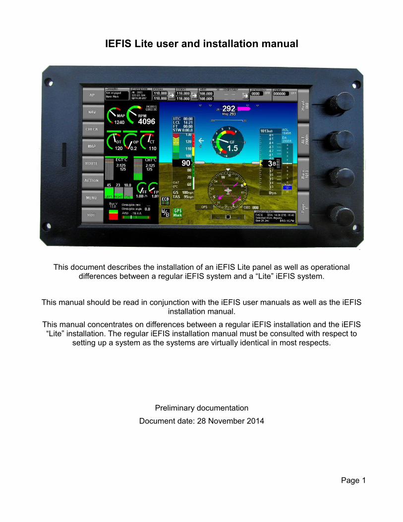
IEFIS Lite user and installation manual
This document describes the installation of an iEFIS Lite panel as well as operationaldifferences between a regular iEFIS system and a “Lite” iEFIS system.
This manual should be read in conjunction with the iEFIS user manuals as well as the iEFISinstallation manual.
This manual concentrates on differences between a regular iEFIS installation and the iEFIS“Lite” installation. The regular iEFIS installation manual must be consulted with respect to
setting up a system as the systems are virtually identical in most respects.
Preliminary documentation
Document date: 28 November 2014
Page 1

Table of ContentsGeneral........................................................................................................................................3Differences between iEFIS and iEFIS Lite..................................................................................4The iEFIS Rear panel layout.......................................................................................................5
GPS antenna..........................................................................................................................5Power / RS232 port 1 connector.............................................................................................5CAN Bus / RS232 port 2.........................................................................................................6Pitot and Static port.................................................................................................................7The internal AHRS..................................................................................................................8Reset gyro bias ......................................................................................................................9AHRS Rate.............................................................................................................................9
Dual panel installations...............................................................................................................9Audio output..............................................................................................................................10Ambient temperature sender....................................................................................................10Before first flight........................................................................................................................10Typical post installation checks and tasks.................................................................................11Maintenance items....................................................................................................................13Cautions....................................................................................................................................14
Touch screen.........................................................................................................................14Cleaning the screen..............................................................................................................14Temperature..........................................................................................................................14Vibration ...............................................................................................................................15Mounting location..................................................................................................................15
CAN bus primer.........................................................................................................................15Making twisted wire...............................................................................................................16Shielded, twisted wires.........................................................................................................16Basic wiring checks...............................................................................................................16CAN cheats...........................................................................................................................16
Specifications............................................................................................................................17Panel dimensions......................................................................................................................18
Page 2
GeneralThe iEFIS “Lite” EFIS is based on the modular iEFIS infrastructure but is aimed at an overall simplified installation for aircraft that do not require some of the hardware interfaces a regular iEFIS system provides.
The iEFIS “Lite” uses the same firmware as a regular iEFIS system and thus provides the same functionality with the proviso that only functions that require a particular hardware interface not available in the “Lite” are unavailable.
Up to 2 panels may be connected in a single system via the CAN bus to share peripherals.
iEFIS Discovery Lite: 7” screen size panel iEFIS Explorer Lite: 8.5” screen size paneliEFIS Challenger Lite: 10.4” screen size panel
As of writing of this document the following MGL devices are compatible with the iEFIS “Lite” system:
SP-6 CAN: Compass/Magnetometer (up to 2 units)SP-7 CAN: AHRS (up to 4 units). Note the “Lite” has a built in AHRS so the SP7 is optional.SP-10 CAN: Flap, trim and gear controller (up to 6 units, up to 2 functions/unit, 6 functions max)RDAC XF: Engine monitoring interface (up to 4 units/engines)RDAC CAN: ECU interface (up to 2 units/engines)MGL V6: COM radio (including full remote control)MGL V10: COM radio (including full remote control)MGL ECB system (up to 8 units, 64 breakers)MGL Autopilot servos (Bank, Pitch, Yaw)MGL/Garrecht mode-s transponder
The following third party products are compatible with the iEFIS system:
Garmin SL40 COM radioGarmin SL30 NAV/COM radioGarmin G430W and newer GPS/NAV/COM systemsSandia aerospace STX-165R mode-c transponderTrig TT21/TT22 mode-s transponders fitted with MGL CAN interfaceVertical power VPXNexNAV FAA certified GPS receiver
Traffic systems: NAVWorx ADSB, FLARM, XRX PCAS
External autopilots can be connected to NMEA (RS232 port).
Page 3
Differences between iEFIS and iEFIS Lite
IEFIS regular IEFIS Lite
ARINC 3 x RX, 1 x TX Not available
Analog navigation support for older NAV systems
4 x balanced inputs Not available
Gillman code transponder encoder interface
Yes Not available
Analog inputs 8 8 *1)
Digital inputs 8 8 *1)
Digital outputs 4+1 Alarm 4 + 1 *1)
RS232 ports 6 2 + 4 *2)
CAN bus 2 1
Airspeed range Up to 600mph with highspeediBOX at sea level
Up to 280 mph
Altimeter range Up to 40.000ft Up to 36.000ft
AOA Yes *1)
OAT Yes Internal. External *1)
Dual power supply inputs Yes No
Wifi link to external applications
Yes (requires Wifi interface module)
No
Video inputs 4 x PAL/NTC None
Video outputs 1 x VGA None
Redundancy Full, comprehensive Partial
*1) Requires optional iEFIS extender module
*2) Optional iEFIS extender module provides 4 RS232 ports for a total of 6 usable ports
The IEFIS “Lite” features a built in airspeed sensor and altimeter from which also vertical speed is derived. It also features a 50 channel WAAS/RAIM capable GPS designed to the requirements for DO-229C class Beta-1 (Timeouts chosen for the En-route case).
A typical minimal iEFIS “Lite” system consists of:
1 x iEFIS Lite panel.
1 x SP-6 magnetic compass (optional, GPS can be used as track angle source if heading is not needed).
1 x RDAC XF (Optional, only needed if engine monitoring is required).
Page 4
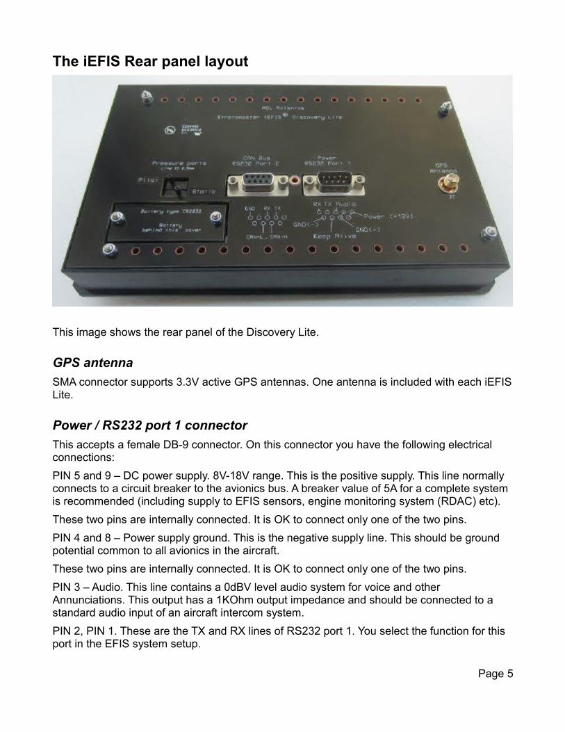
The iEFIS Rear panel layout
This image shows the rear panel of the Discovery Lite.
GPS antenna
SMA connector supports 3.3V active GPS antennas. One antenna is included with each iEFISLite.
Power / RS232 port 1 connector
This accepts a female DB-9 connector. On this connector you have the following electrical connections:
PIN 5 and 9 – DC power supply. 8V-18V range. This is the positive supply. This line normally connects to a circuit breaker to the avionics bus. A breaker value of 5A for a complete system is recommended (including supply to EFIS sensors, engine monitoring system (RDAC) etc).
These two pins are internally connected. It is OK to connect only one of the two pins.
PIN 4 and 8 – Power supply ground. This is the negative supply line. This should be ground potential common to all avionics in the aircraft.
These two pins are internally connected. It is OK to connect only one of the two pins.
PIN 3 – Audio. This line contains a 0dBV level audio system for voice and other Annunciations. This output has a 1KOhm output impedance and should be connected to a standard audio input of an aircraft intercom system.
PIN 2, PIN 1. These are the TX and RX lines of RS232 port 1. You select the function for this port in the EFIS system setup.
Page 5

PIN 7 – This is the “Keep alive” line. You must connect this line to your aircraft's battery “+” terminal so it remains connected at all times even when the aircraft is shut down for a prolonged period. The battery “-” terminal must remain connected to the EFIS GND(-) terminalas well.
The EFIS will draw a very small current in the micro-ampere range through this connection in order to keep certain data such as date/time, hobbs, virtual fuel levels etc alive during power down. Failing to connect this line will cause the EFIS to draw the required current from an internal CR2032 type coin battery. This battery can be replaced – it is accessible under the cover on the left.
PIN 6 – RS232 ground. This pin is normally left unconnected even if the RS232 port is used. Equipment connected here is assumed to operate from the same supply as the EFIS so no additional ground connection is needed or desired (if connected, a ground fault could potentially destroy the EFIS or the connected equipment). This line is normally only used if the connected equipment is not supplied from the aircraft's power system, such as a portable,battery operated device for instance.
Should it be for some reason required to have this ground connected while both EFIS and connected equipment are powered from the same electrical system, it is recommended to wire a 100 ohm resistor or fuse in line to act as over current protection in the event of a ground fault.
CAN Bus / RS232 port 2
The CAN bus is used to connect to MGL peripherals such as:
RDAC XF, SP-6, SP-7, SP-10, Garrecht and Trig transponders (with MGL CAN interface), MGL ECB, autopilot servos, etc.
The CAN bus us a two wire balanced signaling system that excels in robustness and EMI performance. The single CAN bus connects to multiple devices making installation of a complete EFIS system very simple and fast.
Wiring details are found at the end of this manual.
The RS232 port 2 function is selected in the EFIS setup menu.
Note: If you have the optional iEFIS Extender module, connect RS232 port 2 to this modules EFIS Lite interface (RX <-> TX and TX <> RX). In this case your selected RS232 port 2 function moves to the extender which offers a total of 5 RS232 ports.
These ports will be numbered as 2,3,4,5 and 6 from viewpoint of your EFIS.
Please note comments with respect to usage of the RS232 ground pin (pin 5) in the above section describing RS232 port 1. The same applies here.
PIN 2 – RS232 TX
PIN 3 – RS232 RX
PIN 5 – RS232 Ground (not connected in most installations)
PIN 7 – CAN bus line “High”
Page 6

PIN 8 – CAN bus line “Low”
All other pins are “no connect”.
Pitot and Static port
The connections for pitot and static port require usage of a 2.5mm inside diameter PVC, nylonor neoprene hose. A section of hose suitable for constructing adapters to other hose diameters is included with the iEFIS Lite.
For many slower, unpressurized aircraft static ports are not used. In this case it is OK to leavethe static port unconnected. This assumes that the EFIS static port will be exposed to ambientpressure that is not affected in a meaningful way by the aircraft's speed or attitude.
If this cannot be guaranteed you must used a correctly located static port and connect this to your EFIS.
A standard pitot tube airspeed sender should be connected. Ensure that the pitot tube is correctly installed, that there are no air leaks or blockages and that the pitot tube is not affected in a bad way by airflow around the aircraft or aircraft protrusions. On propeller driven aircraft be especially concerned about the effect the propeller has on airflow. Make sure air pressure as seen by the pitot tube is affected only by airspeed and not any other sources.
The EFIS instrument setup menu contains a multipoint airspeed calibration system that you can use to trim out unavoidable errors.
Page 7
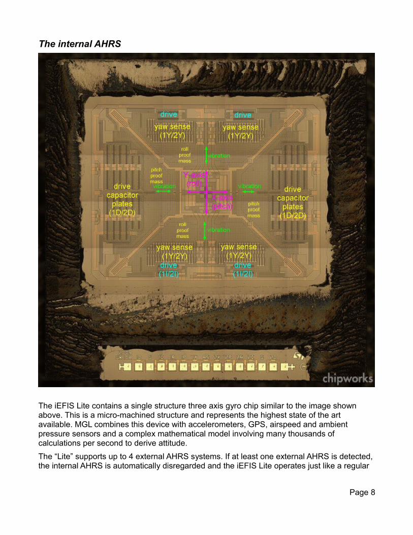
The internal AHRS
The iEFIS Lite contains a single structure three axis gyro chip similar to the image shown above. This is a micro-machined structure and represents the highest state of the art available. MGL combines this device with accelerometers, GPS, airspeed and ambient pressure sensors and a complex mathematical model involving many thousands of calculations per second to derive attitude.
The “Lite” supports up to 4 external AHRS systems. If at least one external AHRS is detected,the internal AHRS is automatically disregarded and the iEFIS Lite operates just like a regular
Page 8
iEFIS with respect to the external AHRS devices.
The “Lite” features a setup menu for its built in AHRS under the System Setup -> Internal and Extender Sensor setup -> IMU Setup menu.
This menu provides two functions:
Reset gyro bias
To cater for aging of the gyro structure, the gyro rate bias needs to be reset occasionaly. Typically it is recommended to perform this function once per year or whenever the EFIS needs to be operated under temperature extremes. You must also perform this function after you have changed the AHRS rate setting to cater for differences in bias between the modes.
AHRS Rate
In most applications a maximum gyro rate of 250 degrees per second is used. This is the fastest rotation rate any of the three gyros can measure. This setting allows a good compromise between resolution and range.
For aerobatic purposes you can select a rate of 500 degrees per second. This reduces resolution and accuracy slightly but allows a much larger measurement range. Please select this mode only if you need it.
Important note:
After you have changed the gyro rate setting you must perform the “reset gyro bias”. Failing todo so will cause very poor performance of the AHRS.
Do not perform either of these functions in flight. These functions may only be performed with the aircraft stationary on the ground and with engines off.
Dual panel installationsIt is possible to install two panels and share CAN bus and RS232 peripherals between the two panels.
In such a case each panel operates independently with one panel designated “master” and the other panel becomes the “standby” panel.
The pilot panel is normally designated “master”. The master panel controls all peripherals while a slave panel may only “listen” to peripherals.
The panels two CAN buses must be connected together and the two RS232 ports must also be wired in parallel. If you are using the EFIS Extender on RS232 port 2, the extender will be used by both panels with the master being in control.
You need to configure the master and standby panels in the “Operations setup menu”. One panel is master, one panel is standby.
The standby panel will become the active controlling panel within two seconds of not detecting the designated master panel.
Page 9
Note: Normal CAN bus wiring applies. A maximum of two 120 ohm termination resistors, one on each end of the bus.
Audio outputThe Lite features an audio output that can output standard iEFIS voice annunciations and sounds to intercom system.
The audio level is standard 2Vpp (0dBV) signal with about 1KOhm output impedance.
The output is not designed to drive headsets or speakers directly. It needs to be amplified. This typically forms part of the intercom system. Wire the output using general audio wiring techniques to a suitable input of the intercom system.
Inputs should be chosen that allow adjustment of audio levels and that will mute the input when radio transmissions are received.
Ambient temperature senderBy default, the Discovery Lite uses an internal temperature sender mounted close to the rear panel. For aircraft where the temperature behind the panel is close to ambient, this may be used as OAT sender. A calibration to cancel out small variations is available in the Internal and External sensor setup menu (This is in System Setup).
Alternatively, a standard MGL LM335 based temperature sender my be connected to a spare RDAC input. Only the first RDAC is considered if your installation has multiple RDACs.
You can select AUX1, AUX2, Oil temperature, oil pressure or the fuel pressure input. If you decide to use one of these, make sure that the corresponding pullup resistor in the RDAC is switched ON. The sensor is connected between the selected input and the ground of the RDAC. Make sure you select a ground point at the RDAC – not anywhere else as this can introduce large measurement errors.
You may also use a K-Type thermocouple (often used as CHT or EGT probes) connected to RDAC TC12.
If you have a iEFIS Extender, this also provides an input for an external MGL OAT sensor.
You can select the desired OAT source in the Internal and External sensor setup menu.
Note: If you select any RDAC input or the Extender and these are not detected, the EFIS will default to the internal temperature sensor.
Tip: you can quickly check the reported temperature in the system diagnostics or any display that has the OAT item.
Before first flightSeveral important steps should be performed once your EFIS has been installed and is working with all connected devices:
Calibration of the internal AHRS.
Page 10
This is an automated procedure which should be done after installation and repeated once per year or if the aircraft is operating under unusual temperature conditions when compared to the last time the calibration has been performed.
Under System Setup -> Internal and Extender setup -> IMU Setup -> Set Gyro bias
Select this function after allowing the EFIS 10 minutes to heat up to typical operating temperature. Keep the aircraft absolutely still (engines off) while the calibration is in progress. This takes a few seconds.
AHRS attitude correction.
After initial installation bank and pitch angles need to be reset. Place the aircraft in flight attitude (as close as you can) then:
Under System Setup -> Setup Horizon sensor ->
Set Slip zero: Sets the “ball” position to zero (middle).
Set Bank angle to zero
Set Pitch angle to zero.
Note that there are limits to the amount of angle error that the system will allow.
For Bank angles, your installation must not deviate more than 5 degrees in any direction.
For Pitch angles, your installation must not be more than 10 degrees nose up and 100 degrees nose down. This means for pitch the panel can be vertical (as in a normal aircraft panel, it may be sloped away from you or may even be horizontal (screen facing up).
For all other pre-flight setups and database installations please consult the iEFIS installation manual, user manual, autopilot manual and the navigation manual plus any other relevant manuals that may be applicable for your installation.
Typical post installation checks and tasksOnce you have installed your EFIS panel and all its peripherals it is time for some basic system tests and database installation tasks. These can be done in any order and the list here shows typical steps. Depending on your particular installation further steps may be needed or some steps are not applicable.
With power applied, ensure the panel is displaying the correct supply voltage (typically around12V). Do not operate the system from a nearly drained battery.
Push down the second rotary control from the top and apply power. This brings up the touch screen calibration. Perform the calibration by touching 5 points accurately with about 100 grams force. When done test your result and accept if you have achieved a good calibration. This should be done once after the panel is installed. The touch screen is very stable and further calibrations should not be required.
In the system setup menu -> Standard system selections, select your desired screen layouts and display modes from the built in selections or if you have made your own screens, install these into the Screens folder using the file manager or the install tasks menu and then select to use these screens in this menu. You can also use a mixture of built in screens and partial
Page 11
screens you made yourself using the individual screen item enables.
In the system setup menu -> System units setup select your desired units of measurement.
Ensure that the altimeter is showing the correct altitude (adjust the barometric pressure setting using the “baro” rotary control or tap on the altimeter tape upper or lower half).
Perform the ASI zero procedure. This is equivalent to adjusting the needle of a mechanical airspeed instrument to point to zero if no air pressure is present on the pitot/static ports.
Apply a light pressure to the pitot port and verify that you get an airspeed reading. Hold the pressure and check for leaks – the airspeed indication must not drop until you release pressure. If you have a airspeed indicator test set, verify correct reading within 1%.
Check to make sure all user airspeed and altimeter calibrations are at zero (the factory settings may show a small number – take a note of these numbers for future reference. Thesenumbers should never be changed).
Ensure that all devices that you have connected to the CAN bus are working. Most of these devices will feature a LED that will signal that it is seeing the EFIS via the CAN bus (check in the individual devices manuals for the flash sequences).
You can also check the CAN diagnostics (under the Diagnostics menu). You should see a message rate indication (number of messages received per second).
If you are using one or more RDAC systems for engine monitoring, you will spend some time in the Engine setup menu. Here you will select probe types, measurement ranges, alarm levels etc. Ensure that all engine indications are reading as expected during a short engine test run. If you are using EGT and CHT probes (thermocouples), ensure that you have selected the channels used in the TC setup menu. Also ensure that you have selected the correct scan chains (EGT and CHT would normally use the same scan chain number for eachengine). Scan chains determine which probes should be assumed to be connected to the same engine – this way the EFIS can group the probes to a particular engine.
If you are using fuel level and fuel flow senders, spend some time in the fuel related setup menu. If you are using physical fuel level senders – you will need to setup the tank sizes and also obtain the various level calibration points (see iEFIS installation manual). For flow senders, ensure you have entered the correct k-factor (number of pulses for one LITER of liquid flow).
With the GPS antenna installed and the aircraft outside of your hangar, ensure that the GPS is acquiring a fix (typically one minute to first fix).
The iEFIS Lite is shipped with a World wide terrain database preinstalled. This data lives in your Terrain folder (check the files with the file manager).
The iEFIS is also shipped with a World Wide vector map file (roads, rivers, places, urban areas, lakes etc). This is installed in your Maps folder.
You need to install a navidata.ewd file containing aeronautical information (airspaces, airports,waypoints, navigation aids, obstacles etc). This is done using the Install tasks menu (install navidata). There are various free and paid subscription sources for navidata available. Contact your MGL Avionics distributor if it is not clear where to obtain this data. Depending onthe data source, updates may be available typically on a monthly bases so you will be
Page 12
installing this file often.
With a valid GPS fix, change the viewing page to one that has a map. Touch the map and then select “mode” and change to vector map (often you will also select “track up” for this mode). Using the map menu, select your vector map display options. Please note that many of these options are local to a particular zoom level. This allows you to customize the display as you would like it (for example you may prefer less information when viewing a larger area of the map). Go through every zoom level (the lower 5 are relevant) and select options to use for each.
If you have obtained raster map files for your EFIS (you can also make your own using the free MGL MapMaker2 application) you can install these using the Install tasks menu. Switch between raster and vector maps at any time using the map Mode.
If you have autopilot servos installed, configure the autopilot setting as needed. The details you need to know here are in the separate autopilot manual.You will start by enabling the servos you have (most often bank and pitch), selecting start settings for the various control algorithms (use the defaults from the autopilot manual) and you need to “identify” the servos. The servos need to be told what they are. For this only one servo at a time is connected and then you identify that servos function (this is stored in the servo itself). You will then also set control limits which also automatically identifies the servo direction.Finally, there is a servo test facility that is helpful to check the servos functionality when connected to your control surfaces.Lastly, if all is well use the autopilot pre-flight check to verify correct operation of the controls and direction of control.Ensure that you have selected the servo torque to be adequate for the expected force but not too great so you cannot overpower the autopilot in an emergency.
Note: if you are planning to use autotrim (via an SP-10) or trim indication on the screen, servotorque must not be greater than 85% to allow stick force measurement to operate.
Work your way through the many menus in the system and check all that is applicable for your aircraft.
In particular view the “Operations setup menu”. One of the most important tasks is to select how flight detection is to work. Most use “automatic mode” based on airspeed and engine RPM triggers to detect start of flight.
I you have radios, navigation receivers, transponders etc connected, ensure these have been correctly configured in their relevant setup menus (also check the serial port allocation and routing menu for RS232 based devices).
Once everything checks out, you are ready to take your iEFIS for its first flight...
Maintenance itemsEvery year:
Perform “Zero ASI” procedure.Perform Gyro bias zero procedure.
Page 13
Every two years if “Keep Alive” NOT connected to a 12V DC source
– or -
Every ten years if “Keep Alive” connected to a 12V DC source
Replace internal battery type CR2032 (commonly used calculator type coin cell).
Cautions
Touch screen
The iEFIS Lite features a “glass-glass” resistive touch screen which is able to determine contact force, a vital measure to allow use of a touch screen in turbulence.This touch screen will provide a very long life time if treated correctly.
Never apply a large force to the screen. Forces in excess of 2Kg will destroy the screen resistive elements resulting in “dead spots” where no touch can be detected.
The firmware is designed to warn if force detected is high and if a certain threshold is exceeded the screen will dim and a red warning will be shown.
Please note that “dead spots” on the screen can only be caused in this manner (squashing of the spacer dots by excessive force) and this is NOT covered under warranty. This requires replacement of the entire screen assembly as the touch screen element forms a functional part of the LCD display itself (the touch screen contains the LCD polarizer).
Cleaning the screen
Should the screen require cleaning, please use a soft cloth and water. A mild detergent such as a dish washing liquid can be used if needed. Never use aggressive chemicals such as petroleum products, acids, bleaches etc. Never use any form of abrasive material or pads.
Temperature
The EFIS panel and all its parts are sensitive to excessive temperature. Large temperature changes can place physical force on electronic interconnections and many repeated cycles may eventually break connections. In addition to this electronic components such as memory chips and processors will be compromised if they are running too hot or too cold.
One of the most severe conditions may arise from excessive temperature build up behind the panel on a hot sunny day with sunlight falling onto the aircraft dash. Hot air tends to rise and is trapped if no ventilation on top of the panel is provided.
Please ensure that your aircraft has adequate “behind the panel” ventilation to prevent this from happening. If you regularly operate in very hot conditions it is a good idea to install a small DC fan behind the panel to aid the flow of cooler air to replace heated air.
Large temperature variations may affect the internal gyroscope which is used as a bases for your artificial horizon. Should you operate in a climate zone that features cold winters and hot
Page 14
summers, it is a good idea to perform the gyro bias zero procedure as seasons change. This will ensure optimum performance of the AHRS.
The EFIS should not be operated at temperatures below -20 degrees C (actual panel temperature). If you need to operate at these temperatures, please allow the panel some timeto heat up (it will self heat when powered) before commencing flight operations. A time of 5-10minutes is recommended.
Vibration
Any device is sensitive to vibration in some form or another. Vibration imparts mechanical stress on components but also affects sensors.Ensure that your panel is not exposed to excessive vibrations caused by your engine – this can degrade the performance of your AHRS. Should it not be possible to operate the internal AHRS due to excessive panel vibration or movement relative to the air frame, consider using an external AHRS mounted in a more suitable location connected via the CAN bus. The “Lite” can accept up to 4 external AHRS systems (for redundancy).
Mounting location
The iEFIS “Lite” internal AHRS must be mounted relatively close to the aircraft's center of rotation. A typical small aircraft panel is suitable from a distance to this point.In cases where the distance exceeds 6 feet additional flight testing to evaluate the effect needs to be performed. As distance increases, centrifugal forces will be seen by the AHRS asthe aircraft changes attitude. This will cause the AHRS to miss-interpret attitude leading to compromised performance. In such a case, consider a correctly located external AHRS connected to the CAN bus.
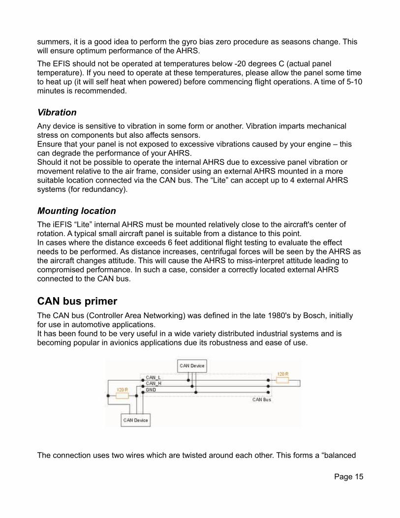
CAN bus primerThe CAN bus (Controller Area Networking) was defined in the late 1980's by Bosch, initially for use in automotive applications.It has been found to be very useful in a wide variety distributed industrial systems and is becoming popular in avionics applications due its robustness and ease of use.
The connection uses two wires which are twisted around each other. This forms a “balanced
Page 15
transmission line”. It helps to reduce emissions and also makes the link more robust against external interferences.
The CAN bus is always implemented as a single cable allowing only short stubs to connect to equipment along the route. Never implement a CAN bus as a “star” or other wiring topology.
The CAN bus requires termination resistors at each end of the bus. These are to be 120 ohm resistors. 1/4W or 1/8W resistors are usually used here. The resistors must be installed at each end of the bus, not in the center or anywhere else.
For short CAN runs (less than three meters) it is possible to install a single resistor of lesser value (not less than 60 ohms) at any location in the cable run (a 100 ohm resistor works well).
The two wires are referred to “CAN High” and “CAN Low”. These must connect to the corresponding lines at the devices. Never swap these connections (I.e. Never connect CAN Hto CAN L at any device) as the CAN bus will not be able to function.
Never run the CAN bus connection inside a wire harness next to sensitive connection such asaudio or signal wires. Never run the CAN bus next to RF cables.
Making twisted wire
It is very easy to make your own twisted wire. Simply take two equally long wires (for example5 meters) in parallel and tie one end (both wires) to a fixture (a door handle works well). Insertthe other end (both wires) into a drill. Stretch the wires so they are straight. Run the drill for a few short bursts at slow speed and you have a created a perfect twisted pair !
Shielded, twisted wires
It is possible to purchase shielded, twisted wire. This can be used in applications where there may be electrical noise issues. In this case we advise to connect the shield to ground AT A SINGLE LOCATION ONLY. This prevents creating a “ground loop” which can cause EMI issues.
Basic wiring checks
You can use a volt meter to perform basic checks on a CAN connection.
With at least one device connected and powered you should be able to measure voltages of around 1.0 – 3.0 volts on each cable with respect to ground. The voltage should appear very similar on each connection.
Use your meters resistance measurement function to check the installation of the termination resistors. The CAN bus, if terminated with a 120 ohm resistor on each end of the bus should give you a reading of 60 ohms.
CAN cheats
Yes you CAN cheat. As most aircraft CAN bus installations have relatively short CAN bus wirelengths (perhaps 10-15 feet) and the CAN bus baudrate has been chosen relatively low at 250KBits/second to boost reliability, you can in most cases get away with installing a single
Page 16

resistor at any point of the CAN bus. A resistor value of at least 60 ohms needs to be used (68ohms would be the next higher standard value). Single resistors up to 100 ohms can be used without degrading the CAN bus in our experience.
Note: The CAN bus will not work or not work reliably if no resistor is installed. Do not do that under any circumstance.
SpecificationsSupply voltage: 8V – 28V DC. Over voltage surge and reverse voltage surge protected. Over voltage surge protection threshold 33V.
Supply current: 0.25A @ 13.8V backlight level at minimum (night operation mode).
Supply current: 0.55A @ 13.8V backlight level at maximum (day operation mode).
Airspeed indicator range: 28 to 280 mph.
Altimeter range: -1200 to 36000 ft.
AHRS roll/pitch/yaw rates: 250 degrees per second any axis (Normal mode). 500 degrees persecond any axis in aerobatic mode (user selectable).
Touch screen life expectancy: 1 million touches at any one spot with a force not exceeding 2 Newtons (about 200 gram force).
Audio output: Impedance 1KOhm. 0 dBV (2V pp).
Weight: 670 grams typical.
Page 17
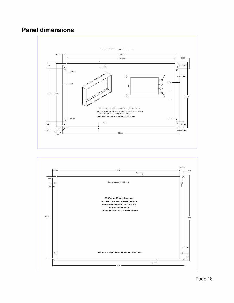
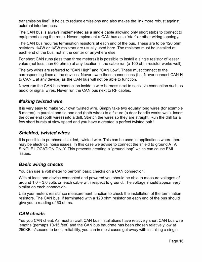
Panel dimensions
Page 18
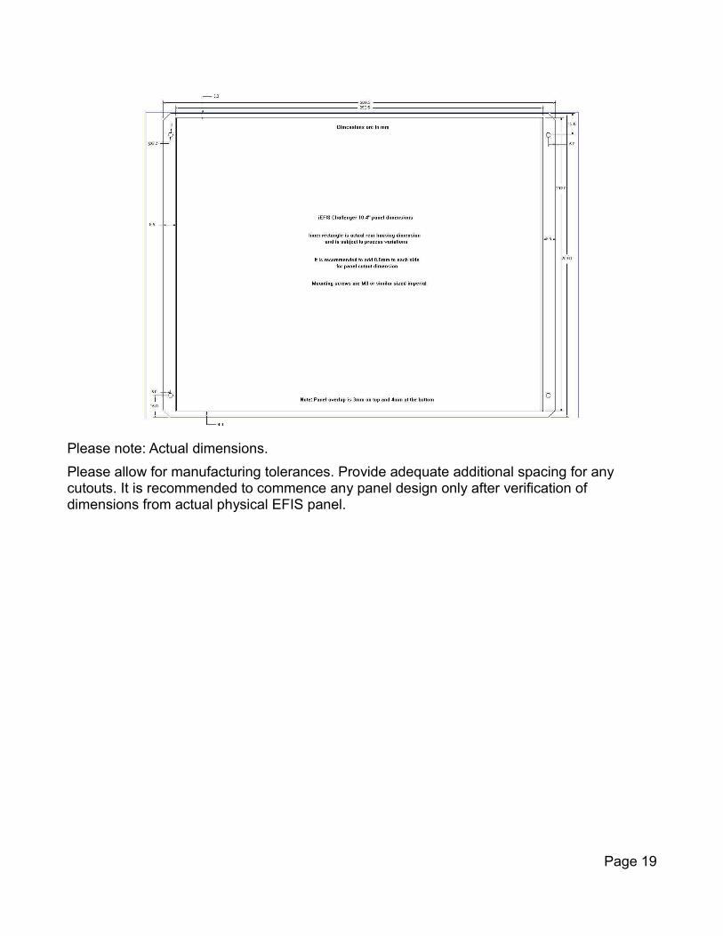
Please note: Actual dimensions.
Please allow for manufacturing tolerances. Provide adequate additional spacing for any cutouts. It is recommended to commence any panel design only after verification of dimensions from actual physical EFIS panel.
Page 19