iepc11 paper - simulation of the spacecraft electric...
TRANSCRIPT
The 32nd International Electric Propulsion Conference, Wiesbaden, Germany
September 11 – 15, 2011
1
Simulation of the Spacecraft Electric Propulsion Interaction on DubaiSat-2 using SPIS
IEPC-2011-012
Presented at the 32nd International Electric Propulsion Conference,
Wiesbaden • Germany September 11 – 15, 2011
Juyoung Lee1, Alexander Reissner2 and Martin Tajmar3
Department of Aerospace Engineering, KAIST, Daejeon, Republic of Korea
and
Yunhwang Jeong4 Satrec Initiative, Daejeon, Republic of Korea
Abstract: In this paper, the interaction between DubaiSat-2 and its hall thruster is investigated. The simulation is made using SPIS software, simulating spacecraft-plasma interaction based on the Particle-in-Cell method. A new particle injection source model, developed by Astrium SAS, is used with a quasi-neutrality assumption and an fluid electron model. The plume simulation is first compared with the experimental data, then parasitic power loss, cathode damage and sputtering is analytically calculated from the simulated plasma environment. Finally, the effect of a plume shield on the plasma environment is studied.
Nomenclature nᵢ, nₑ = electron, and ion density [m-3] mᵢ, mₑ = molecular mass of electron and ion [kg] Φp = plasma potential [V] kB = Boltzmann constant, 1.3807x10⁻²³ JK-1
e = elementary charge, 1.602x10⁻¹⁹ C q = electric charge [C] Te = electron temperature [K] γ = adiabatic constant C1 = temperature constant j = current density [A/m2] Y = sputtering yield [atoms/ion] Eth = sputtering threshold [eV] ε = reduced energy Sn = nuclear stopping cross section k = energy transfer factor ke = Lindhard electronic stopping coefficient Us = energy of sublimation [eV]
1 MSc Candidate, Department of Aerospace Engineering, [email protected] 2 Ph.D Candidate, Department of Aerospace Engineering, [email protected] 3 Associate Professor, Department of Aerospace Engineering, [email protected] 4 Chief Engineer, Space Program Division, [email protected]
The 32nd International Electric Propulsion Conference, Wiesbaden, Germany
September 11 – 15, 2011
2
I. Introduction ecause of the high specific impulse, electric propulsion systems are recognized as a promising candidate for future space missions. However, since they expel plasma to push the spacecraft, using electric propulsion
introduces complex plasma interactions with the spacecraft. For example, energetic ion beams can sputter thermal coatings or cover glasses, which results in the degradation of thermal and power performance. These sputtered materials can also deposit on other surfaces and decrease for example the performance or solar cells. In addition, the plume plasma can interfere with sensors. All these effects can significantly limit the spacecraft lifetime and its capabilities. Because of these concerns, there have been many studies to estimate such effects. As a result, several codes such as EPIC3, COLISEUM4 and SMART-PIC5 were developed and showed enough ability to analyze the common issues like sputtering and contamination. However, since they more focuses on simulating the electric thruster plume, they show weaknesses in simulating general plasma interaction including both charging and electric propulsion related issues. Additionally, the charging of spacecraft affects electric thruster related problems. For example, the surface draws more contaminants when they are more negatively charged. Therefore, there have been efforts to integrate these plume analysis codes into charging analysis programs like the American NASCAP and European SPIS software. As a result, the latest NASCAP-2k included EPIC.6 It was also studied to integrate COLISEUM into NASCAP-2k.7 In European a consortium led by Astrium SAS was contracted by ESA to implement electric propulsion related particle-injection models into SPIS.8 These models are based on the thruster model used in SMART-PIC, but unlike NASCAP-2k, which connects EPIC and NASCAP using SOAP (Simple Object Access Protocol), the model is redeveloped as an subordinate code for SPIS. This removes the communication between two different programs which makes the simulation inefficient. SPIS, which has been European charging analysis software based on Particle-in-Cell method, now has an ability to simulate the plume of Hall, gridded ion and FEEP thruster by injecting particles into computational region. The current paper describes the first application of this software to a commercial satellite, called DubaiSat-2. This satellite is made by the Korean satellite manufacturer Satrec-i, in close collaboration with the Emirates Institution for Advanced Science and Technology (EIAST). On the satellite, the recently developed Satrec-i Hall thruster is used. In this paper, the Korean Hall thruster is first simulated using the new source model and the result is compared with the experimental data. Then the plasma distribution around spacecraft is calculated with properly tuned thruster parameters. Parasitic power loss, cathode current increment and sputtering of interconnectors and bus bars are estimated next. Finally, the use of a plume shield is investigated.
B
The 32nd International Electric Propulsion Conference, Wiesbaden, Germany
September 11 – 15, 2011
3
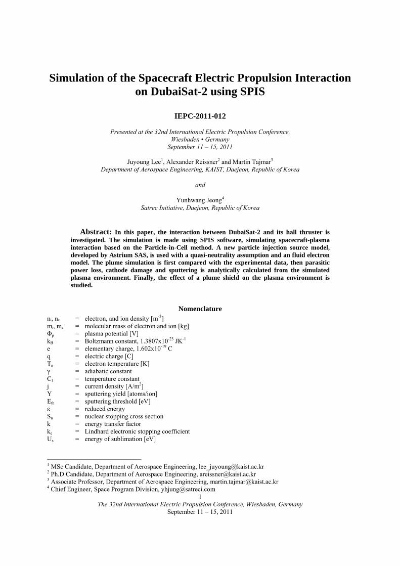
II. DubaiSat-2 & Problem Definition DubaiSat-2 is designed as a remote sensing satellite which operates at a 600km sun-synchronous orbit for 5 years.
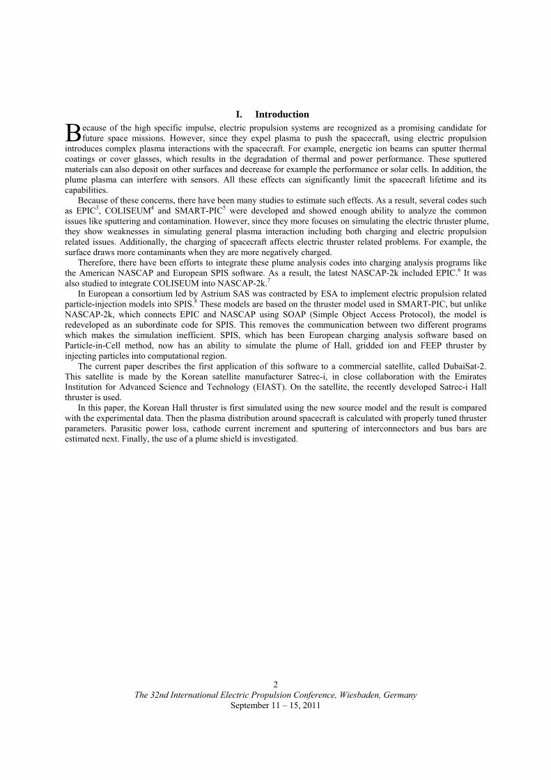
It features the recently developed Satrec-i Hall thruster, which operates with a Xenon flow of 7sccm and an anode discharge voltage of 250 V giving 7 mN of thrust for 10 minutes a day. Instead of a hollow cathode which is commonly used for Hall thrusters, a microwave cathode, developed by JAXA, is used to provide 0.5-0.6A of neutralizing electrons. Also, unlike common configurations using a Zener diode to isolate the cathode common and the spacecraft ground, the cathode and the anode are both directly biased to the spacecraft ground. With this configuration, the spacecraft floating potential can be intentionally controlled. For example, if the absolute ground potential of the microwave cathode is -30V at nominal condition and the bias from the spacecraft ground to cathode is 30V, then absolute spacecraft ground potential is around 0V.
Figure 1. DubaiSat-2
Because all spacecraft components are positioned out of 60 degrees from hall thruster axis, the main beam ions
do not directly hit any spacecraft components. Therefore, sputtering from main beam ions is not significant for DubaiSat-2. Also, the contamination is not significant since the total operating time is as short as 300 hours and sputtered thruster material from Hall thrusters are usually ceramic for this short operating time. These ceramic materials do not significantly change the optical and thermal properties of surfaces.9
Anode
Keeper
Heater
CathodeGround
SpacecraftGround
Solar Panel
a) Satrec-I Hall thruster b) Grounding Scheme
Figure 2 Satrec-i Hall thruster and Grounding scheme

The 32nd International Electric Propulsion Conference, Wiesbaden, Germany
September 11 – 15, 2011
4
On the other side, while the spacecraft floating potential is intentionally fixed at a certain value using the thruster, there can be significant current collection from the surrounding dense plasma. Since this current makes a circuit through the cathode, the current collecting surfaces and the spacecraft ground bars, this can cause parasitic power loss or decrease of the cathode lifetime. To reduce these effects, the spacecraft floating potential should be kept as low as possible.
However, the low floating potential can make significant sputtering of surfaces with a negative potential. Not only sputtering itself changes the surface properties, but also sputtered material can make contamination. Since perpetual degradation of performance can be caused from this, this problem also has to be considered. In short, the spacecraft floating potential should be decided so that both current collection and sputtering is limited within an acceptable range.
First, the positions and the areas of exposed conductive surfaces must be known to estimate these effects. Most surfaces of DubaiSat-2 are covered with MLI blankets and radiators, and as the outmost layers, 25μm Kapton and 125μm Teflon are used without conductive coatings. Also, two sub antennas on the same side as the Hall thruster are coated with Teflon. Therefore, the spacecraft is mostly insulated except for bus bars, interconnectors and solar cell sides. 32 bus bars with a 5mm width equal to about 50% of the total conductive area, and both solar cell sides with 150μm width and interconnectors with 1mm width occupy 25% each.
One solar panel consists of 6 parallel lines with 26 serial connected triple-junction solar cells. Each cell has a voltage from 2.371V (maximum power) to 2.667V (open circuit) and current from 0.478A (maximum power) to 0.497A (short circuit). Solar array negative is connected to spacecraft ground, thus the potential of the solar panel is at maximum 69.3V higher than the spacecraft ground. This value is taken as the worst case.
a) Bus bar and interconnector b) Solar cell side
Figure 3. Current collectors, both sides of interconnectors are exposed
+69.3V
+0V+0V
+69.3V
Figure 4. Solar cell arrangement
The 32nd International Electric Propulsion Conference, Wiesbaden, Germany
September 11 – 15, 2011
5
III. Simulation Method
A. SPIS software SPIS is an European software for spacecraft-plasma interaction simulation. The simulation is based on the
Particle-In-Cell (PIC) method and both hybrid-PIC and full-PIC are supported. It can simulate surface interactions such as photoelectric current and secondary emission according to the given material properties. SPIS showed comparable results with pre-existing NASCAP software in GEO charging analysis.
However, in spite of its maturity in GEO charging simulation, the analytical current collection model is not yet well established. Although hybrid-PIC supports exponential current model which fits well for repelled species, the estimation is too high for accelerated species. Full-PIC gives reliable results but this requires the mesh size smaller than the Debye length and the current collectors. Considering that the typical Debye length for LEO environment (1e11m-3, 0.1-0.2eV) and thruster induced environment (1e11-1e13m-3, 0.1-2eV) is from few millimeters to few centimeters, whereas the characteristic length of DubaiSat-2 is about 2 meters, this is a computationally too expensive option.
Thus, in this paper, SPIS is only used as a tool to calculate the plasma environment around the spacecraft. Since the Debye length is very short compared to the spacecraft, the plasma properties at a few Debye length distance are taken as ambient plasma conditions necessary to calculate the current collection analytically.
B. Potential Solver For high plasma densities and a large computational region, it has been common to assume Maxwell-Boltzmann
distribution for electrons, which is called hybrid-PIC. Also, since the Debye length is much smaller than the size of computational region, quasi-neutrality is often assumed everywhere. Integration of these two assumptions makes the plasma potential to be calculated directly from Eq.(1),
refref
iebp n
nln
e
Tk (1)
where Φp is plasma potential [V], kb is Boltzmann constant, Te is electron temperature, e is elementary charge and ni is ion density. nref and Φref are respectively the plasma density and the plasma potential at a certain point. This model is known to give nearly identical results compared to models using Poisson's equation while it is generally more stable and faster. Although this approach cannot simulate the plasma sheath where quasi-neutrality breaks, it is still useful enough to get the plasma conditions outside the sheath region.
However, since Maxwell-Boltzmann distribution only holds for isothermal, collisionless, unmagnetized and currentless electrons, Eq.(1) needs some modifications. In reality, the electron temperature is higher near the thruster exit plane and net current of electrons exists. Also electron mobility is affected by collisions and magnetic field. Several studies have been made to include some of these effects10, but for simplicity only an adiabatic electron model is included in SPIS. This is given as
11 CnTk γeeb (2)
where γ is the adiabatic constant and C1 is a temperature constant. Several experimental data has shown good agreement with this model in terms of electron temperature. Integrating the Maxwell-Boltzmann distribution and adiabatic electron model, the potential solver becomes
refref
iref,ebP n
n
)(e
Tk
11
1
(3)
It should be noted that the reference parameters have to be decided with great care. Since effects from the current, collisions and the magnetic field are not considered, the potential distribution in reality is still different especially near the exit plane. This makes it impossible just using experimentally measured exit potential. Instead, the exit potential should be decided from charge-exchanged (CEX) ion energies and ambient conditions. For example, if the thruster is firing in LEO environment, the potential should be 0V at LEO plasma density and temperature conditions. At the same time, the simulated CEX ion energies should be similar to experimental values.
The 32nd International Electric Propulsion Conference, Wiesbaden, Germany
September 11 – 15, 2011
6
C. Hall Thruster Model The detailed thruster model developed at Astrium SAS is used.8 This model simulates a surface injection of
various species into the computational region. For example, Xe+, Xe++ and neutral Xe are simulated for the Satrec-i Hall thruster. As major input parameters, it requires inner/outer radius, thrust, mass flow rate, doubly-charged ion ratio, ionization efficiency, cathode mass flow ratio and beam divergence angle. Ion velocity is calculated from the inputs and ions are distributed on the exit plane according to a selected uniform or cosine distribution. Neutrals are distributed similarly. The model is described in Ref.8.
D. Collision Model Up to now, only a CEX collision model is included in SPIS. The current CEX model generates CEX ions from
the Monte-Carlo method and decreases the weight of the ions to keep the charge conservation. CEX cross section is given as either the tabulated temperature-cross section relationship or as a constant number.
Neutral flows can be given in 3 ways. First, we can assume background neutrals by specifying a background pressure. Second, we can use an analytical neutral distribution calculated from the mass fraction of neutrals. And third, PIC modeling for neutrals can be used.
E. Current Collection Model The current collection scheme strongly depends on the relative size of the collectors to the Debye length. When
the Debye length is much smaller than the size of collectors, the surface potential of collectors does not spread far. Therefore, the effective area collecting electrons or ions is nearly the same as the area of collectors. This case is commonly referred as thin-sheath current collection. On the other hand, when the Debye length is comparable to the collector size, the surface potential spreads far around collectors. This makes effective current collecting area larger than the collector surface area. This is usually called think-sheath or orbit limited current collection.
For DubaiSat-2, the sizes of current collectors are 5mm (bus bars), 1mm (interconnectors) and 150μm (solar cell sides). Considering that Debye length for the plume environment (1e11-1e13m-3) is a few millimeters to a few centimeters, the orbit limited current model should be used. The orbit-limited electron collection for a 2-dimensional strip is derived in Ref.11 as
)Tk/e(erfee
Tk
Tk
ejj eb
Tk/eeb
ebth
eb
1
2
112 (4)
where Φ is surface potential, T is corresponding ion or electron temperature and jth is thermal electron current given by
m
Tknqj b
th 2 (5)
where n is electron density, m is electron mass and q is the electron charge. When the ion density, ion mass and ion charge is used, jth means thermal current for ions. In our paper, Eq.(4) is modified to consider both electrons and ions.
)Tk/q(erfeq
Tk
Tk
q)jj(j b
Tk/qb
bdriftth
b
12
112 (6)
where jdrift is drift current defined as,
nqvjdrift (7)
where v┴ represents the drift velocity toward a current collecting surface. It should be noted that the solar cell sides are blocked by the solar panel surface and the cover glasses. They do not only physically block trajectories, but also their negative potential effectively reduces the current collection. Bottom surfaces of interconnectors are also expected to collect much less current compared with the top surface, since trajectories to the bottom surfaces are blocked by the panel surface. Although physical blocking is much less as for the bus bars, space-charge effects are considered to be significant since their width is similar to the Debye length.

The 32nd International Electric Propulsion Conference, Wiesbaden, Germany
September 11 – 15, 2011
7
In Ref.11, these effects were considered using 2-dimensional simulation and trajectory analysis. Unfortunately, these additional methods are not possible with the SPIS software. Thus the above model is used to estimate an upper bound for the current collection including both electrons and ions. For repelled species, the exponential current model is used given as
Tk/qdriftth
be)jj(j (8)
Snap-over is neglected since the surface potential never exceeds 70V, which is typical snap-over threshold.
D. Sputtering Model Sputtering of the bus bars and interconnectors can be calculated from the current collection. The ion energy is
derived from the difference between the plasma potential and the surface potential. It should be noted that doubly charged ions have twice the energy of singly charged ions. A semi-empirical equation derived by Yamamura and Tawara12 is used to calculate the sputtering yield given as
s/
th.
e
n
s E
E
k
S
U
*Q.Y
21
301
1
0420
(9)
where M1 and M2 are the molecular mass of incident ions and target atoms, and Z1 and Z2 are the atomic number of incident ions and target atoms, respectively, Eth is the threshold energy and E is incident ion energy in eV. The threshold energy is defined as
21
2121
76
751
MM
MM
k/U.
k/UM/M.E
s
sth
(10)
where Us is the energy of sublimation. The energy transfer factor k is given as
2
21
214
MM
MMk
(11)
Other components are defined as,
31 71 /M
W
(12)
21
21
12150
12
5112
56012
165008750
003502490
MM
MM
M/M.M/M.
M/M.M/M.*
.
..
(13)
E)ZZ(ZZ
.
)MM(
M/// 2132
232
12121
2 032550
(14)
n///n s)MM(
M
)ZZ(
ZZ.S
21
12132
232
1
217884
(15)
where sn is the reduced nuclear stopping power,
)..(.
).ln(.sn
708188263561
71824413
(16)
And ke is the Lindhard electronic stopping coefficient given as
4332
232
1
212
321
212
231
23210790
///
//
//
/
e )ZZ(
ZZ
MM
)MM(.k
(17)
The 32nd International Electric Propulsion Conference, Wiesbaden, Germany
September 11 – 15, 2011
8
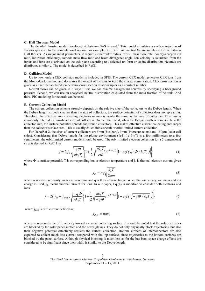
where Q, W and s are fitting parameters given for target atoms. In DubaiSat-2, a Silver plated Invar36 alloy is used for the interconnectors and the bus bars. Invar36 mainly consists of 36% Nickel and 64% Iron thus the properties of Invar36 are calculated from weight-averaged parameters between Iron and Nickel. The results are shown in Table 1 and Fig.5.
Xenon Iron Nickel Invar36 Silver M 54 55.845 58.6934 56.870 107.8682 Z 131.293 26 28 26.722 47 Us 4.28 4.44 4.3376 2.95 Q 0.75 0.94 0.8184 1.08 W 1.2 1.33 1.2468 1.03 s 2.5 2.5 2.5 2.8
Table 1. Sputtering parameters for Incident Xenon and target materials
IV. Results
A. Thruster Plume Simulation As the first step, the thruster input parameters should be selected to provide good agreement with experimental
data. The experimental data is provided by Satrec-i and the test was made in the KAIST GDPL vacuum chamber with a diameter of 1m and a length of 1.9m. The pressure was kept around 2e-4torr during the test. Unfortunately, an uncertainty of measured values is unavoidable for this high background pressure. According to Ref.13, 10% error on measured thrust and current density can exist for this pressure, due to entrained ambient neutrals. Also high pressure can cause pressure induced instability of operation. However, 10% error is considered acceptable.
Most parameters were given from the thruster specification and only the divergence angle is changed to match the experimental data. For the potential solver, adiabatic parameters are set to give 0V at typical polar LEO condition (1e11, 0.2eV) and the exit plane potential is chosen to produce 20eV CEX ion energies at 90° position. As the measurement for CEX ion energies has not been not made for Satrec-I hall thruster, this value is taken from Ref.1
20 40 60 80 1001E-5
1E-4
1E-3
0.01
0.1
1
Sp
utte
ring
Yie
ld, a
tom
s/io
n
Ion Energy, eV
Silver Invar36
Figure 5. Sputtering yields for Silver and Invar36

The 32nd International Electric Propulsion Conference, Wiesbaden, Germany
September 11 – 15, 2011
9
Satrec-i Hall Thruster
Inner diameter(m) 0.016 Outer diameter(m) 0.025
Thrust(N) 0.0067 Mass flow(kg/s) 6.881e-7
Cathode split 0.143 Ionization efficiency 0.95
Doubly-charged ion ratio 0.1 Inner divergence angle(°) -20 Outer divergence angle(°) 20
Potential Solver Adiabatic constant, γ 1.23
Temperature constant, C1 0.000607
Table 2. Input parameters for DubaiSat-2 hall thruster
-120 -100 -80 -60 -40 -20 0 20 40 60 80 100 1201E-3
0.01
0.1
1
10
100
Cu
rre
nt D
en
sity
, A/m
2
Angle, degree
Experiment, P=2e-4 torr SPIS, P=2e-4 torr SPIS, P=0 torr
Figure 6. Comparison of current densities at sweep radius 0.37m

The 32nd International Electric Propulsion Conference, Wiesbaden, Germany
September 11 – 15, 2011
10
Even though the newly developed source model could successfully simulate the hall thruster plume for different
ambient pressures, it was not possible to accurately reproduce the experimentally measured current density in the background region. The simulated result shows a current which is about twice the measured one – which is still acceptable for our further analysis. This is not an unexpected result when elastic collisions are not included.14 From the physical point of view, this is because generated CEX ions are never accelerated again by elastic collisions. In this paper, this effect is considered in interpreting the results.
(a) P=2e-4torr (b)P=0torr
Figure 7. Plasma density
(a) P=2e-4torr (b)P=0torr
Figure 9. CEX Xe+ energy distribution
(a) P=2e-4torr (b)P=0torr
Figure 8. Plasma potential

The 32nd International Electric Propulsion Conference, Wiesbaden, Germany
September 11 – 15, 2011
11
B. Spacecraft-hall thruster simulation As the next step, the plasma environment was calculated for the spacecraft-Hall thruster system. From the
symmetry of the satellite, only 1/4 of the satellite is simulated. Also, camera baffle and sun-shield were neglected because they barely contribute to the plasma distribution.
Because the main purpose of the simulation is to get the plasma properties near the current collecting surfaces, the characteristic length of the mesh does not have to be smaller than the Debye length. The characteristic length is set to be 2cm and the plasma properties are measured at the centerline 4cm from solar panel. This characteristic length is more than 5 times the Debye length and it is assumed that the surface potential is perfectly shielded at this distance.
O+ plasma with 1e11m-3, 0.2eV and 7562m/s ram speed is implemented as the LEO environment. Although energetic electron flow exists in the polar region where DubaiSat-2 fires the thruster, their current is usually less than 1μA/m2 and negligible. Photoelectric emission is much larger than energetic electrons as tens of μA/m2, but still much smaller than ion current collection from a dense plasma, which is found to be in the range of few hundreds μA/m2.
Ambient neutrals such as O and N can also be neglected since their densities are on the order of 1e14m-3, whereas Xe neutral density near the exit is about 1e16-1e18m-3 according to the simulation.
0.0 0.1 0.2 0.3 0.4 0.5 0.6 0.7 0.8 0.91E10
1E11
1E12
1E13
Pla
sma D
ensi
ty, m
-3
Distance along Solar Panel, m
Xe+
Xe++
0.0 0.1 0.2 0.3 0.4 0.5 0.6 0.7 0.8 0.91E-5
1E-4
1E-3
Dri
ft C
urr
en
t De
nsi
ty, A
/m2
Distance along Solar Panel, m
Xe+
Xe++
a) Number density b) Drift Current Density
Figure 11. Plasma properties along the solar panel
a) Plasma potential b) Plasma density
Figure 10. Plasma potential and electron number density

The 32nd International Electric Propulsion Conference, Wiesbaden, Germany
September 11 – 15, 2011
12
C. Current collection through solar panels Current collection is calculated from the simulated plasma environment and the result is shown in Fig.12.
At zero spacecraft floating potential, the model predicts 49mA of electron collection. Considering that 24 solar cell strings produce a current of 11.52A in total, the power loss is about 0.4% which is not critical. Even compared to the nominal cathode current, this is less than 10%. This is in the acceptable range, considering that our current collection model is an upper bound and the CEX ion current is overestimated.
D. Sputtering analysis The sputtered thickness is calculated from calculated current density and the sputter yield as calculated from
Eq.(9). The lowest surface potential and the maximum current density are used for an upper bound solution. The sputtered thickness is calculated for 18,250 minutes which is the net operation time of the Satrec-i Hall thruster.
-80 -70 -60 -50 -40 -30 -20 -10 0 100
100
200
300
400
500
600
700
Spu
ttere
d T
hic
knes
s, n
m
Spacecraft Floating Potential, V Figure 13. Sputtered thickness
-80 -70 -60 -50 -40 -30 -20 -10 0 101E-3
0.01
0.1
1
10
100
Co
llect
ed C
urr
ent
, mA
Spacecraft Floating Potential, V
Electron Current Ion Current
Figure 12. Current collection according to spacecraft floating potential
The 32nd International Electric Propulsion Conference, Wiesbaden, Germany
September 11 – 15, 2011
13
It was found that sputtering is not severe enough to sputter away the Silver plating which is typically about 5µm. However, sputtering could still be a problem since sputtered metal ions can deposit on the cover glasses, which results in power loss. The deposition of Silver atoms are not analyzed in detail, but our results suggest that it is better to have a high (more positive) floating potential since the degradation from cover glass contamination is permanent, whereas parasitic power loss from negative potential is temporary.
D. Plume shield Even though sputtering or current collection does not add up to critical results for DubaiSat-2, it is still
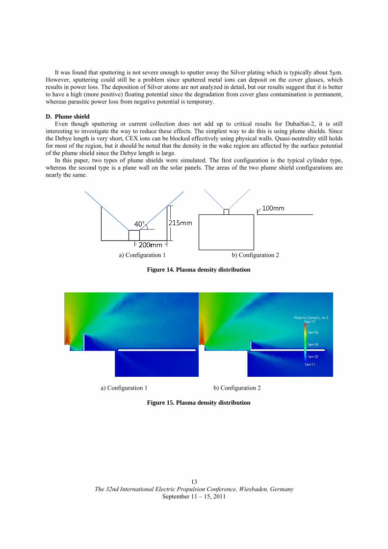
interesting to investigate the way to reduce these effects. The simplest way to do this is using plume shields. Since the Debye length is very short, CEX ions can be blocked effectively using physical walls. Quasi-neutrality still holds for most of the region, but it should be noted that the density in the wake region are affected by the surface potential of the plume shield since the Debye length is large.
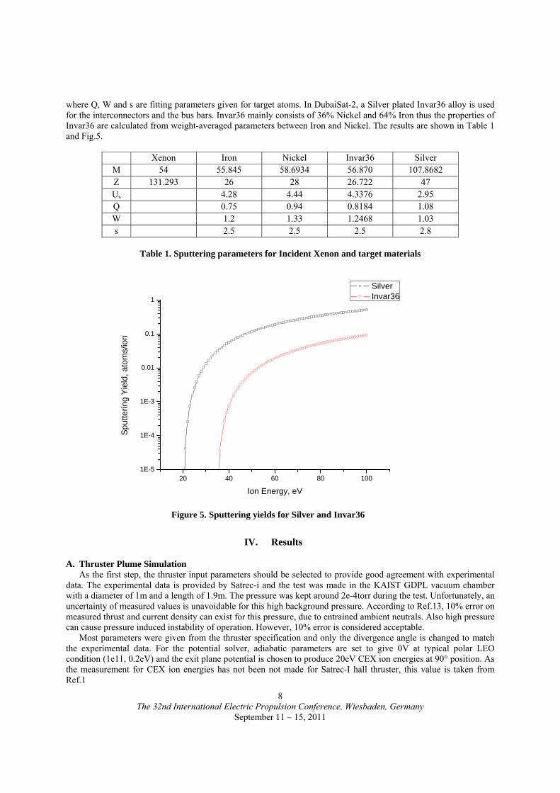
In this paper, two types of plume shields were simulated. The first configuration is the typical cylinder type, whereas the second type is a plane wall on the solar panels. The areas of the two plume shield configurations are nearly the same.
a) Configuration 1 b) Configuration 2
Figure 14. Plasma density distribution
a) Configuration 1 b) Configuration 2
Figure 15. Plasma density distribution
The 32nd International Electric Propulsion Conference, Wiesbaden, Germany
September 11 – 15, 2011
14
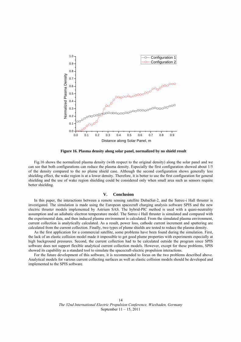
Fig.16 shows the normalized plasma density (with respect to the original density) along the solar panel and we
can see that both configurations can reduce the plasma density. Especially the first configuration showed about 1/5 of the density compared to the no plume shield case. Although the second configuration shows generally less shielding effect, the wake region is at a lower density. Therefore, it is better to use the first configuration for general shielding and the use of wake region shielding could be considered only when small area such as sensors require better shielding.
V. Conclusion In this paper, the interactions between a remote sensing satellite DubaiSat-2, and the Satrec-i Hall thruster is
investigated. The simulation is made using the European spacecraft charging analysis software SPIS and the new electric thruster models implemented by Astrium SAS. The hybrid-PIC method is used with a quasi-neutrality assumption and an adiabatic electron temperature model. The Satrec-i Hall thruster is simulated and compared with the experimental data, and then induced plasma environment is calculated. From the simulated plasma environment, current collection is analytically calculated. As a result, power loss, cathode current increment and sputtering are calculated from the current collection. Finally, two types of plume shields are tested to reduce the plasma density.
As the first application for a commercial satellite, some problems have been found during the simulation. First, the lack of an elastic collision model made it impossible to get good plume properties with experiments especially at high background pressures. Second, the current collection had to be calculated outside the program since SPIS software does not support flexible analytical current collection models. However, except for these problems, SPIS showed its capability as a standard tool to simulate the spacecraft-electric propulsion interactions.
For the future development of this software, it is recommended to focus on the two problems described above. Analytical models for various current collecting surfaces as well as elastic collision models should be developed and implemented to the SPIS software.
0.0 0.1 0.2 0.3 0.4 0.5 0.6 0.7 0.8 0.90.0
0.1
0.2
0.3
0.4
0.5
0.6
0.7
0.8
0.9
1.0
No
rma
lized
Pla
sma
Den
sity
Distance along Solar Panel, m
Configuration 1 Configuration 2
Figure 16. Plasma density along solar panel, normalized by no shield result

The 32nd International Electric Propulsion Conference, Wiesbaden, Germany
September 11 – 15, 2011
15
Acknowledgments The research described in this paper was carried out by the Advanced Space Propulsion Laboratory of KAIST,
under a contract with the Korean satellite manufacturer Satrec-i. The authors greatly appreciate the support from S. M. Kang of Satrec-i providing experimental data and specification of the Satrec-i Hall thruster, as well as the support from Astrium SAS and M. Wartelski providing technical support about the SPIS software and the new Astrium source model.
References 1Azziz, Y. "Experimental and Theoretical Characterization of a Hall Thruster Plume", Ph.D. Dissertation, Department of
Aeronautics and Astronautics, Massachusetts Institute of Technology, 2007 2Parks, D. E. and Katz, I., "A Preliminary Model of Ion Beam Neutralization", Electric Propulsion and Its Applications to
Space Missions, edited by R.C.Finke, Progress in Astronautics and Aeronautics vol.79, 1981 3Mikellides, I. G., Mandell, M. J., Kuharski, R. A., Davis, D. A., Gardner, B. M. and Minor, J., "The Electric Propulsion
Interactions Code(EPIC)", 39th Joint Propulsion Conference, Huntsville, Alabama, July 2003, AIAA 2003-4871 4Fife, J. M., Gibbons, M. R., VanGilder, D.B. and Kirtley, D.E., " The Development of a Flexible, Usable, Plasma Interaction
Modeling System", AIAA-2002-4267 5Tajmar, M., Sedmik, R., Scharlemann, C., "Numerical Simulation of SMART-1 Hall Thruster Plasma Interactions", Journal
of Propulsion and Power, Vol25. No.6, November-December, 2009 6Mandell, M. J., Davis, V. A., Cooke, D. L., Wheelock, A. T. and Roth, C. J., "Nascap-2k Spacecraft Charging Code
Overview", IEEE Transactions on plasma science, vol.34, No.5, October, 2006 7Brieda, L., Barrie, A., Gorrilla, L. M., Mandell, M. and Davis, V., "Integration of the Coliseum Plasma Simulation Tool with
the Charging Code Nascap-2k", IEPC-2007-76 8Wartelski, M., Theroude, C., Ardura, C., Reissner, A., Tajmar, M., Leiter, H., Feili, D., Lotz, B., Gengembre, E., Luna, J. P.
and Bulit, A., "The Assessment of Interaction between Spacecraft and Electric Propulsion Systems Project", IEPC-2011-028(To be published)
9Goebel, D.M., Katz, I., Fundamentals of Electric Propulsion : Ion and Hall Thrusters, Wiley, New Jersey, 2008, Chaps. 8, 4.2.
10Boyd, I. D. and Yim, J. T., "Hall Thruster Plume Simulation Using a Detailed Hybrid Model", AIAA-2004-3952 11Mandell, M. J., Davis, V. A., Gardner, B., Jongeward, G., "Electron Collection by International Space Station Solar Arrays",
8th Spacecraft Charging Technology Conference, Huntsville, Alabama, October 20-24, 2003 12Y. Yamamura, H. Tawara, "Energy Dependence of Ion-Induced Sputtering Yields from Monatomic Solids at Normal Incidence", Atomic Data and Nuclear data tables 62, 149-253, 1996, Article no. 0005 13Randolph, T., Kim, V., Kaufman, H., Kozubsky, K., Zhurin, V., Day, M., "Facility Effects on Stationary Plasma Thruster Testing", IEPC-93-093 14Cheng, S. Y. M., "Computational Modeling of a Hall Thruster Plasma Plume in a Vacuum Tank", MSc Dissertation, Department of aeronautics and Astronautics, Massachusetts Institute of Technology, 2002, p.98