ieplc framework, automated communication in a
TRANSCRIPT

IEPLC FRAMEWORK, AUTOMATED COMMUNICATION IN A
HETEROGENEOUS CONTROL SYSTEM ENVIRONMENT
F. Locci, S. Magnoni, CERN, Geneva, Switzerland
Abstract
In CERN accelerators control system several compo-
nents are essential such as: Programmable Logic Con-
troller (PLC), PCI Extensions for Instrumentation (PXI),
and other micro-controller families. Together with their
weaknesses and their strength points they typically present
custom communication protocols and it is therefore diffi-
cult to federate them into the control system using a single
communication strategy. Furthermore this dependency to
the physical device interfaces and protocols makes most
of the code not reusable and the replacement of old tech-
nology a difficult problem. The purpose of IEPLC ([1]) is
to mitigate the communication issues given by this hetero-
geneity; it proposes a framework to define communication
interfaces in a hardware independent manner. In addition it
automatically generates all the resources needed on master
side (typically represented by a FEC: Front-End Computer)
and slave side (typically represented by the controller) to
implement a common and generic Ethernet communica-
tion. The IEPLC framework is composed of a set of tools,
scripts and a C++ library. The configuration tool allows the
definition of the data to be exchanged and their instantia-
tion on different controllers within the control system. The
scripts generate the resources necessary to the final com-
munication while the library eventually allows the appli-
cation on the master side to send and receive data to/from
the different controllers. This paper describes the different
components of this tool by focusing on its main objectives,
namely: defining standard interconnection ways and clear
communication interface between FECs and controllers;
reducing user developments and configuration time.
CONTEXT
As in all the big plants, CERN accelerator complex re-
quires scalable and sophisticated control systems in order
to maneuver and guarantee the proper functioning of all
the components. To perform data acquisition and actua-
tion over all those equipment a large variety of controller is
adopted. CERN prefers using off-the-shelf controllers so as
to benefit from company support for any issue encountered.
However, there are tasks that standard components cannot
achieve as well as there are tasks for which licenses costs
are prohibitive or not worth the benefit. Finally, depending
on the skills and the background of the user, personal tastes
do matter in this field. Due to all these reasons lot of dif-
ferent components are used at the same time. All of them
have to be integrated in a common structure to cooperate
and federate with all the other devices.
Controller FamiliesIEPLC was initially developed in order to address the
problem of automatic code generation for communication
purposes for PLC devices. It now supports communica-
tion with different controller families but it is intrinsically
designed keeping PLC as reference controller. Different
brands of PLC have been addressed: Siemens SIMATIC-
S7 and Schneider MODICON controllers with their re-
spective development tools (Step-7 and Unity Pro) while
Beckhoff TwinCAT components will be supported before
end of 2013. IEPLC integrates a second controller fam-
ily, widely used at CERN, mainly for instrumentation or
specific systems: PXI and Compact-RIO from National In-
strument (NI). Finally, much less used at CERN but nev-
ertheless interesting, microcontrollers based on simple mi-
croprocessor for embedded system proves very interesting
when size, flexibility, power-consumption and price are the
main issue. Unlike other hardware, the microcontroller
does not specify any communication protocol but was eas-
ily integrated in IEPLC infrastructure using Modbus/TCP
standard already implemented for Schneider PLCs ([4]).
The Three Tier Control SystemCERN’s control system uses industrial components such
as SCADA (Supervisory Control and Data Acquisition) es-
pecially for cryogenic and vacuum systems. The core of
the CERN control infrastructure is however provided by a
custom solution that better fulfills requirements within a
complex accelerators environment (especially for real time
control and timing aspects). As shown in Fig. 1, the control
system splits over three different responsibility tiers which
communicate among them via TCP-IP protocol over Giga-
bit Ethernet connection.
Figure 1: Three-tier control system.
Proceedings of ICALEPCS2013, San Francisco, CA, USA MOPPC031
Integrating Complex or Diverse Systems
ISBN 978-3-95450-139-7
139 Cop
yrig
htc ○
2014
CC
-BY-
3.0
and
byth
ere
spec
tive
auth
ors

Both equipment controllers and Front-End Computers
(FECs) belong to the resource tier. The latter acts as
bridges between the presentation tier (operation tools and
control room software) and the physical layer. The FEC
is implementing the accelerator device model and its pub-
lish/subscribe paradigm and handles timing and synchro-
nization. Two types of FEC are mainly adopted: VME plat-
form with extension modules (Timing, AC/DC, DIO, func-
tion generator, field buses, etc.) and Industrial PC rack-
mounted crate (mostly used for general services and net-
work gateway). Both platforms run 64bits real-time Scien-
tific Linux. The Front End Software Architecture (FESA)
abstracts all these components providing a comprehensive
framework for designing, coding and maintaining Linux
equipment software ([2],[3]). In this context, IEPLC takes
the responsibility for standardising the integration of indus-
trial components within CERN’s controls infrastructure.
CHALLENGES
PLC manufacturers, as well as many other controller
vendors, usually implement a specific communication pro-
tocol for their devices. This implies the customization of
the code used to control such a device, hence reducing its
portability and reusability. This situation is not sustain-
able at CERN given the number and diversity of the control
equipment. In complex control system, operative mode, in-
terfaces and data model definition have priority on deciding
the physical adopted devices. On the other hand, different
technologies can be adopted for similar features and could
expose the same kind of data. Our goal is to find a com-
mon solution allowing communication between FECs and
equipment controllers. The IEPLC framework automates
the code generation for the different controllers and stan-
dardises the communication with them under a simple API,
reducing the amount of the client code, hiding all the pro-
prietary solution and making data structure reusable.
MAIN CONCEPTS
Relying on the users requirements and on the experience
they got for years to integrate industrial components in the
control infrastructure, a set of rules and concepts has been
defined to delimit the scope of the IEPLC product. The
framework has to:
• normalize the controllers connection based on Ether-
net medium
• discharge experts from implementing communication
software, on both side: client and controller
• offer suitable interface for the accelerator De-
vice/Property model
• propose a non-intrusive solution for the controller
software by limiting the use of hardware resources
• define high-level service for the client side (Front-End
software)
• offer fast and lightweight configuration and genera-
tion tools
• be open and scalable for future extensions
• be portable by limiting the dependencies as much as
possible
SOLUTION
IEPLC framework consists of four main components:
• A generic device-oriented data model which defines
and structures the data transmission between the con-
trollers and the front end computers.
• A configuration tools to define the IEPLC connection
and to generate the data mapping for the controller and
the client software.
• A generic access library for the front end client that
implements the communication contract.
• A diagnostic and debugging tool which relies on the
generic library allowing the users to quickly and easily
access the IEPLC controllers for testing.
The Device Data ModelThe IEPLC configuration tool allows creation of the two
XML documents required for the generation process. The
class document (also called design document) defines the
structure of the exchanged data in a completely hardware
independent manner. The elementary data of the class is
called a ’register’. Registers are grouped into structures
called ’blocks’ which will be transmitted in a single trans-
action. A block has an access mode applied to all its regis-
ters (read-only, write-only or read-write). The layout of the
class (registers and blocks position) and generic attributes
of the registers (format, dimension) are used to map the
registers in the memory of the controller at the deploy-
ment phase. The mapping document (or deployment doc-
ument) defines the binding between the physical device and
the class instances. It has the purpose of instantiating the
classes for a physical controller. IEPLC allows the same
class to be instantiated over different heterogeneous con-
troller. In the same way instances of different classes can
coexist on the same controller on the same time. A graphi-
cal representation of such a concept is given in Fig. 2.
The WorkflowEditing and storing XML documents is done using a Java
Configuration tool which relies on XML schema and con-
straint language (CliXML) to automatically validate the
correctness of the class and mapping documents, Fig. 3
[stage 1]. The Generation [stage 2], fully automated by a
set of python scripts, generates an XML document used to
provide the library with all information required to com-
municate (hostname, protocol, mapping, etc.) and a set of
documents containing the code to be uploaded on the con-
troller itself [stage 3]. The library that is instantiated by
MOPPC031 Proceedings of ICALEPCS2013, San Francisco, CA, USA
ISBN 978-3-95450-139-7
140Cop
yrig
htc ○
2014
CC
-BY-
3.0
and
byth
ere
spec
tive
auth
ors
Integrating Complex or Diverse Systems

Figure 2: PLC mapping concept.
the client application running on the FEC (FESA server,
python scripts, C/C++ software, etc.) first loads the param-
eter file(s) [stage 4] and eventually begins communicating
with the physical controller(s) [stage 5].
Figure 3: IEPLC Workflow.
The Communication ProtocolStandard protocols. The PLC communication proces-
sors (CP) offer passive server functionality (Siemens S7
PUT/GET and Modbus/TCP for Schneider) which can be
used to avoid specific PLC code for data communication.
In the same way, IEPLC relies directly on CVI Network
Variable mechanism (CNV [5]) for NI controllers com-
munication and Modbus/TCP for Rabbit microcontrollers
([4]). Using native protocols has the great advantage of not
impacting the equipment process and freeing the user from
communication aspects. It also simplifies considerably the
diagnosis of communication since transmission behaviour
is pre-defined and independent. In return, IEPLC service is
based on polling mechanism and does not support data sub-
scription but can be easily implemented from upper layers
if required.
Data consistency. Since IEPLC protocol is based on
asynchronous mechanism, it cannot guarantee that each
data block is transmitted consistently when it exceeds the
maximum size defined by the CP hardware. Particular cau-
tions are required in this case: limited block size, single
block transaction and use of uninterruptible memory trans-
fer within the controller process.
Data persistency. Unlike volatile variables, initial value
or processing value of persistent data (constants, com-
mands, settings, etc.) must be consistent on both sides
(FEC and controller) each time a connection is established.
The IEPLC library supports the automatic synchronization
of the persistent registers at connection time relying on the
specialist configuration: Controller or FEC is the backup
source, respectively Master or Slave mode.
Database. IEPLC class instances are not directly ex-
posed to the supervision level. It is therefore not necessary
to define them in the central database; NFS file system has
been chosen to store and manage all IEPLC configurations.
This solution further increases the product portability.
The Source Code GenerationUsing native protocols of the Ethernet CP and keeping
full control of the communication from the FEC simplifies
greatly the generated code required for the controller side.
In fact, a simple shared data structure is generated. The
user can easily import the code in his project without inter-
fering with the equipment process if already exists. The
transmission delays are directly linked to the number of
exchanged frames. In order to optimize the traffic IEPLC
can generate contiguous arrangement of blocks containing
the data of all the device collection (known as “BLOCK
mode”). In contrast, when performance is not a priority,
user can choose the “DEVICE mode” which offers a more
natural organization of the data and allows the specialist to
use the object-oriented capabilities for certain PLCs. The
addressing of a register for NI controller is much simpler
since the data is not allocated in memory but simply dis-
tributed on the network. In this case, IEPLC just specifies
a “uniform resource locator” based on the IEPLC compo-
nents and respecting the Labview variable definition.
The CLIB
IEPLC C++ library handles the communication between
the FEC and the device whose source code has been gen-
erated. At run-time it loads the correct parameter file de-
pending on which class/version and which controller the
user tries to communicate with and hides all the commu-
nication issues through a very simple and high-level API
Proceedings of ICALEPCS2013, San Francisco, CA, USA MOPPC031
Integrating Complex or Diverse Systems
ISBN 978-3-95450-139-7
141 Cop
yrig
htc ○
2014
CC
-BY-
3.0
and
byth
ere
spec
tive
auth
ors
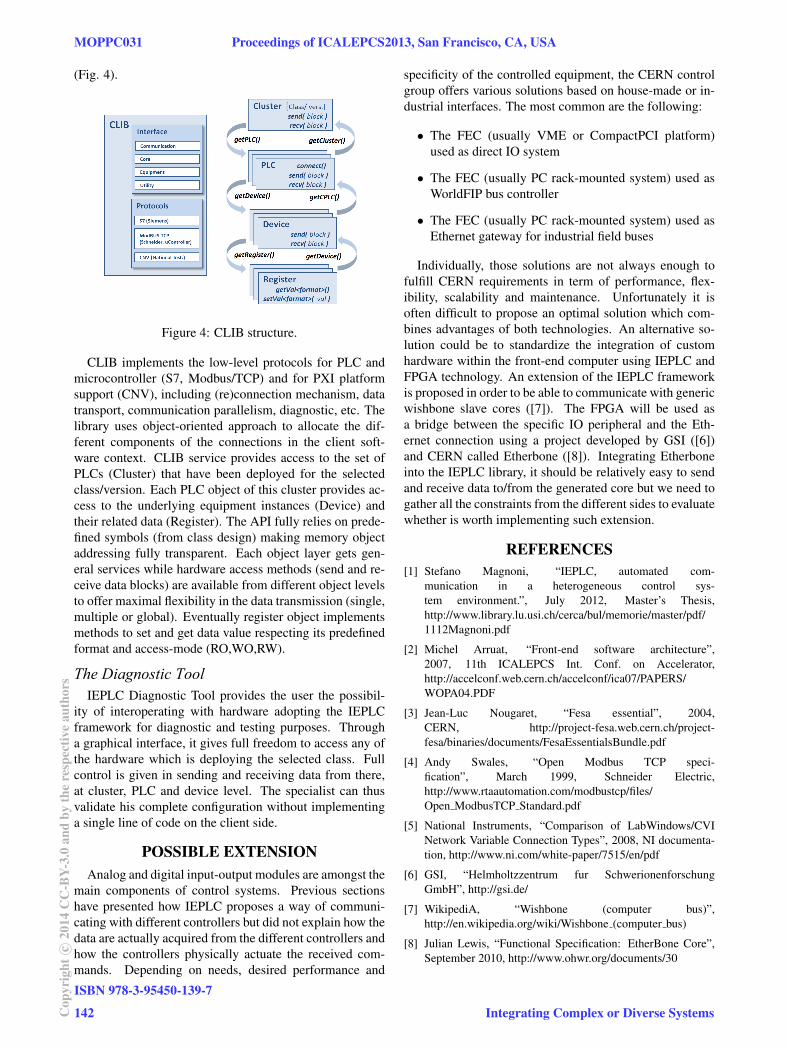
(Fig. 4).
Figure 4: CLIB structure.
CLIB implements the low-level protocols for PLC and
microcontroller (S7, Modbus/TCP) and for PXI platform
support (CNV), including (re)connection mechanism, data
transport, communication parallelism, diagnostic, etc. The
library uses object-oriented approach to allocate the dif-
ferent components of the connections in the client soft-
ware context. CLIB service provides access to the set of
PLCs (Cluster) that have been deployed for the selected
class/version. Each PLC object of this cluster provides ac-
cess to the underlying equipment instances (Device) and
their related data (Register). The API fully relies on prede-
fined symbols (from class design) making memory object
addressing fully transparent. Each object layer gets gen-
eral services while hardware access methods (send and re-
ceive data blocks) are available from different object levels
to offer maximal flexibility in the data transmission (single,
multiple or global). Eventually register object implements
methods to set and get data value respecting its predefined
format and access-mode (RO,WO,RW).
The Diagnostic ToolIEPLC Diagnostic Tool provides the user the possibil-
ity of interoperating with hardware adopting the IEPLC
framework for diagnostic and testing purposes. Through
a graphical interface, it gives full freedom to access any of
the hardware which is deploying the selected class. Full
control is given in sending and receiving data from there,
at cluster, PLC and device level. The specialist can thus
validate his complete configuration without implementing
a single line of code on the client side.
POSSIBLE EXTENSION
Analog and digital input-output modules are amongst the
main components of control systems. Previous sections
have presented how IEPLC proposes a way of communi-
cating with different controllers but did not explain how the
data are actually acquired from the different controllers and
how the controllers physically actuate the received com-
mands. Depending on needs, desired performance and
specificity of the controlled equipment, the CERN control
group offers various solutions based on house-made or in-
dustrial interfaces. The most common are the following:
• The FEC (usually VME or CompactPCI platform)
used as direct IO system
• The FEC (usually PC rack-mounted system) used as
WorldFIP bus controller
• The FEC (usually PC rack-mounted system) used as
Ethernet gateway for industrial field buses
Individually, those solutions are not always enough to
fulfill CERN requirements in term of performance, flex-
ibility, scalability and maintenance. Unfortunately it is
often difficult to propose an optimal solution which com-
bines advantages of both technologies. An alternative so-
lution could be to standardize the integration of custom
hardware within the front-end computer using IEPLC and
FPGA technology. An extension of the IEPLC framework
is proposed in order to be able to communicate with generic
wishbone slave cores ([7]). The FPGA will be used as
a bridge between the specific IO peripheral and the Eth-
ernet connection using a project developed by GSI ([6])
and CERN called Etherbone ([8]). Integrating Etherbone
into the IEPLC library, it should be relatively easy to send
and receive data to/from the generated core but we need to
gather all the constraints from the different sides to evaluate
whether is worth implementing such extension.
REFERENCES
[1] Stefano Magnoni, “IEPLC, automated com-
munication in a heterogeneous control sys-
tem environment.”, July 2012, Master’s Thesis,
http://www.library.lu.usi.ch/cerca/bul/memorie/master/pdf/
1112Magnoni.pdf
[2] Michel Arruat, “Front-end software architecture”,
2007, 11th ICALEPCS Int. Conf. on Accelerator,
http://accelconf.web.cern.ch/accelconf/ica07/PAPERS/
WOPA04.PDF
[3] Jean-Luc Nougaret, “Fesa essential”, 2004,
CERN, http://project-fesa.web.cern.ch/project-
fesa/binaries/documents/FesaEssentialsBundle.pdf
[4] Andy Swales, “Open Modbus TCP speci-
fication”, March 1999, Schneider Electric,
http://www.rtaautomation.com/modbustcp/files/
Open ModbusTCP Standard.pdf
[5] National Instruments, “Comparison of LabWindows/CVI
Network Variable Connection Types”, 2008, NI documenta-
tion, http://www.ni.com/white-paper/7515/en/pdf
[6] GSI, “Helmholtzzentrum fur Schwerionenforschung
GmbH”, http://gsi.de/
[7] WikipediA, “Wishbone (computer bus)”,
http://en.wikipedia.org/wiki/Wishbone (computer bus)
[8] Julian Lewis, “Functional Specification: EtherBone Core”,
September 2010, http://www.ohwr.org/documents/30
MOPPC031 Proceedings of ICALEPCS2013, San Francisco, CA, USA
ISBN 978-3-95450-139-7
142Cop
yrig
htc ○
2014
CC
-BY-
3.0
and
byth
ere
spec
tive
auth
ors
Integrating Complex or Diverse Systems